


YIELD MONITOR 2000
Operators Manual
Manual written with assistance from:
Tri-Tech Communications & Publications, 1636 13th St., Boone, IA 50036

Yield Monitor 2000 |
General |
Ag Leader Technology
Welcome |
Welcome to the Ag Leader Technology family. Ag Leader Technology is |
|
dedicated to developing advanced, yet practical and cost-effective tools for |
|
grain production. Above all, however, we are dedicated to meeting your |
|
needs for support of existing products and development of product |
|
improvements. |
We want to hear from you! Feel free to call any time to discuss:
∙Operational problems with your system
∙Features you don’t like about your system
∙Features you would like added to your system
We will do our best to ensure that you are happy with your current system and that it is upgraded in the future to better meet your needs.
System Upgrades Ag Leader Technology will periodically mail to you a program chip that replaces the existing chip in your monitor console. The new chip will upgrade your monitor, make it easier to use, and may add new features.
To receive an upgrade chip and new product news, you must send in or fax (515-232-3595) the Registration Form that is at the beginning of the operator’s manual. Our mailing address is:
Ag Leader Technology
1203A Airport Road
P.O. Box 2348
Ames, IA 50010
Limited Warranty Ag Leader Technology will repair or replace at no charge any component of the Yield Monitor 2000 system that fails during normal service on the combine model for which the system is intended to be used within two years from the date of first use.
Warranty is not provided for damage resulting from abuse, neglect, accidents, vandalism, acts of nature, or any other causes that are outside the normal, intended use of the Yield Monitor 2000 system.
June 1997 |
1-1 |

General |
Yield Monitor 2000 |
|
Ag Leader Technology |
|
|
|
Ag Leader Technology shall not be liable for indirect, incidental, or |
|
consequential damages to the dealer, end user, or third parties arising from |
|
the sale, installation, or use of the Yield Monitor 2000 system. |
Service |
|
If you have a problem with your system, call us directly at the phone number |
|
|
below. If we determine you have a hardware failure, we will ship |
|
replacement hardware immediately. Our mailing address and phone numbers |
|
are: |
|
Ag Leader Technology |
|
1203A Airport Road |
|
P.O. Box 2348 |
|
Ames, IA 50010 |
|
Phone: 515-232-5363 |
|
Fax: 515-232-3595 |
|
Note: Return failed hardware to us by UPS (preferred) or US mail.. |
Copyright Notice |
|
Ag Leader Technology has copyrighted (©1996) the contents of this manual |
|
|
and the operating program for the Yield Monitor 2000 system. No |
|
reproductions of this material may be made without first obtaining the |
|
consent of Ag Leader Technology. |
|
|
Proprietary
Technology Notice
The Yield Monitor 2000 system has patents on its design and operational features. Copying features of this system relating to measurement and calculation of grain flow and weight or organization of field and load data may result in patent infringement.
* * *
1-2 |
June 1997 |

Yield Monitor 2000
Ag Leader Technology
Setup Overview
Important Notices |
The yield monitor must be set up before field operation, but before you begin |
|
|
the setup procedures, read the following notices: |
|
|
∙ You can upgrade the Yield Monitor 2000 console by replacing a |
|
|
computer chip inside the box. To receive the free upgrade chip, you |
|
|
must send in the registration form at the beginning of the operator’s |
|
|
manual. |
|
|
∙ If you plan to make yield maps on your own computer, you will need to |
|
|
use Precision Map 2000 (or another mapping program that can process |
|
|
memory cards from the Yield Monitor 2000) to process the memory |
|
|
cards when they get full. You can also purchase memory cards from Ag |
|
|
Leader Technology. Precision Map 2000 comes with your Yield |
|
|
Monitor 2000 kit. |
|
Section Contents |
|
|
The following subjects are detailed in this section: |
|
|
|
|
|
|
Subject |
Page |
|
General Description |
2-2 |
|
Before Setup |
2-9 |
|
Setting Date and Time |
2-10 |
|
Logging Settings |
2-11 |
|
Settings Under SETUP Key |
2-14 |
|
Setting Swath |
2-17 |
|
Speed Setting |
2-19 |
|
Setting Moisture |
2-21 |
|
Setting Dry % Moisture, Dry Lbs/Bu |
2-22 |
|
Setting Initial Calibration Numbers |
2-23 |
|
Starting, Naming Fields/Loads |
2-25 |
|
Setting Stop Height |
2-31 |
|
Copying Memory to Backup |
2-32 |
* * *
June 1997 |
2-1 |

General Description
Yield Monitor 2000
Ag Leader Technology
Introduction |
The yield monitor is designed to accurately measure and record acres, |
|
moisture, grain weight, bushels, and yield in bu/ac on-the-go. It is GPS |
|
compatible and can log yield mapping data on memory cards. The yield |
|
monitor must be calibrated to be accurate. |
|
If you are using the monitor with a GPS receiver, you must use a |
|
memory card to save GPS information. If you do not have a GPS |
|
receiver, you do not need a memory card; the monitor has enough internal |
|
memory for 976 total loads and 255 total fields which should last the entire |
|
season. |
Monitor |
|
The monitor is organized by fields and loads. A load subdivides a field into |
|
Organization |
smaller sections. A monitor load can be smaller or larger than a combine |
|
tank, wagon, or truck load. It is recommended to use different loads for |
|
different hybrids or varieties or field conditions (like a wet hole). The |
|
operator manually changes the load when it is appropriate to do so while |
|
harvesting. |
Keypad |
|
The monitor has three groups of keys: a top group, a bottom-left group, and |
|
|
a bottom-right group. When you press a key, the monitor beeps. Each key |
|
(particularly the SETUP and MEM keys) have menu items to scroll through |
|
by continually pressing the key to advance to the next menu item under that |
|
key. |
|
|
2-2 |
June 1997 |
Yield Monitor 2000
Ag Leader Technology
General Description
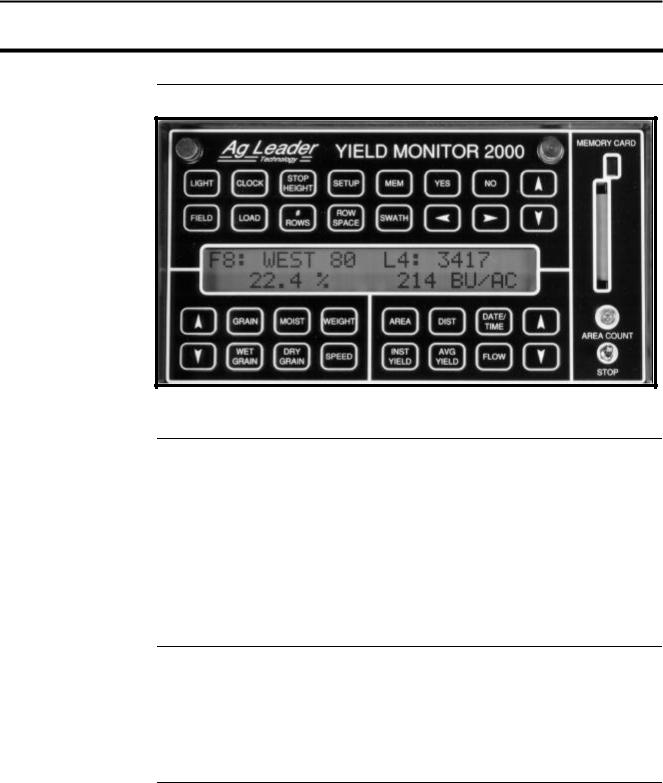
Arrow Keys
Yes/No Keys
Figure 1: Front panel of the yield monitor 2000
When you press a key and a menu item appears, you must use the arrow keys to scroll through a list of settings to select the appropriate setting.
Example: If you pressed the SETUP key to access “LOGGING DEVICE=”, you must use the UP or DOWN ARROW key to set the LOGGING DEVICE = NONE, EXT, or ?M CARD.
Note: After selecting a setting, you need not press another key to save it; the monitor automatically remembers your selection.
When you press a key and the monitor asks you a question, press the YES or NO key to answer the question.
Example: If you pressed the MEM key to access “COPY MEMORY TO BACKUP?”, press the YES or NO key.
June 1997 |
2-3 |

General Description
Yield Monitor 2000
Ag Leader Technology
Top Keys |
The top group of keys is the top two rows of keys (refer to Figure 2 below). |
|
The menu items for these keys appear only on the top line of the display, |
|
except for two menu items accessed through the MEM key. These items |
|
appear on the bottom line of the display. You must use the UP and DOWN |
|
ARROW keys in the top two rows of keys to change a setting for the top |
|
group of keys. |
|
|
|
|
Figure 2: Top group of keys
Bottom-Left Keys The eight keys on the bottom-left of the monitor compose the bottom-left key group. The menu items accessed through these keys appear only at the bottom-left of the display. Use the UP and DOWN ARROW keys in the bottom-left group to change a setting for this group of keys.
Figure 3: Bottom-left key group
2-4 |
June 1997 |
Yield Monitor 2000
Ag Leader Technology
General Description
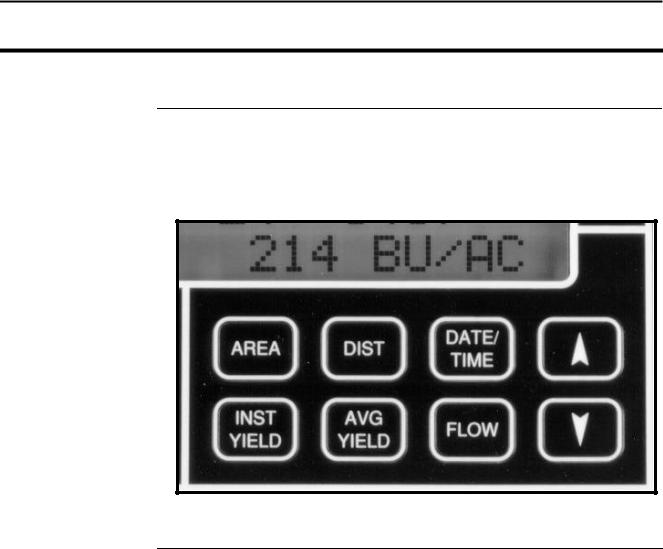
Bottom-Right Keys The eight keys on the bottom-right of the monitor compose the bottom-right key group. The menu items accessed through these keys appear only at the bottom-right of the display. Use the UP and DOWN ARROW keys in the bottom-right group to change a setting for this group of keys.
Figure 4: Bottom-right key group
June 1997 |
2-5 |
General Description
Yield Monitor 2000
Ag Leader Technology
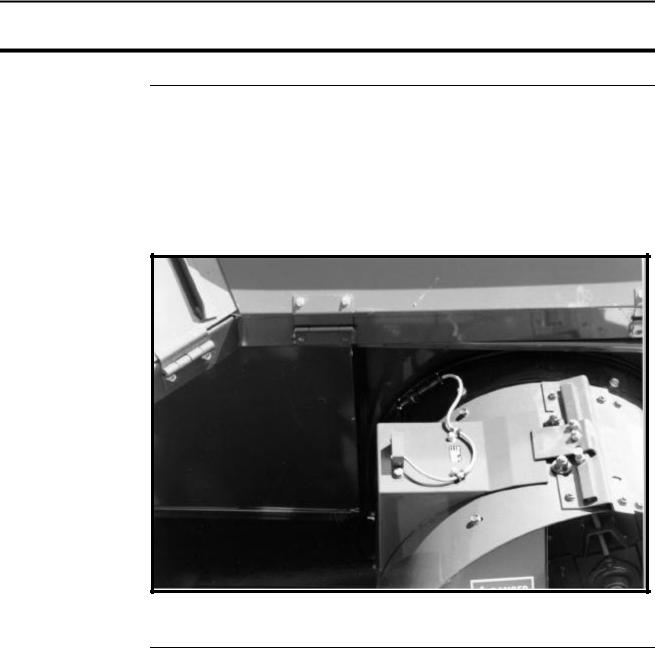
Grain Flow Sensor Below is an example of a grain flow sensor. Your grain flow sensor may look different, depending on which combine model you have. On all combines, the grain flow sensor installs on top of the clean grain elevator. The grain flow sensor measures the grain weight in pounds as you harvest. The clean grain paddles throw the grain, as the paddles rotate around the top sprocket, toward the grain flow sensor. The flow sensor measures the grain weight when the grain strikes the flow sensor impact plate.
Figure 5: Grain flow sensor
2-6 |
June 1997 |
Yield Monitor 2000
Ag Leader Technology
General Description
Moisture Sensor |
Below is an example of a moisture sensor installed on the auger that fills the |
|
combine grain tank. |
|
|
|
|
Figure 6: Moisture sensor
June 1997 |
2-7 |
General Description
Yield Monitor 2000
Ag Leader Technology
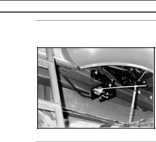
Header Height
Sensor
Below is an example of a header height sensor installed underneath a combine cab. The header height sensor tells the monitor the position of the combine head so that when the head is raised on the row ends as the combine turns around, the monitor stops counting acres.
Figure 7: Header height sensor
* * *
2-8 |
June 1997 |

Yield Monitor 2000
Ag Leader Technology
Before Setup
Using Power
Supply
Setting the Monitor on Field, Load
Other than for setting the stop height and calibrating the distance, the yield monitor console does not need to be in the combine to set it up. You can use the provided power supply (plugs into 120 v outlet) to power up the monitor console inside your home or shop.
When going through the setup procedures, take note of which settings can be set differently for each load. You should setup the monitor with it set to Field 1, Load 1, because any new loads you create will use the settings for the previously created load in that field. The monitor should come from the factory with only Field 1, Load 1 created. Follow the procedure below to try to change to a different field and load to verify that only Field 1, Load 1 has been created. If there is more than one field and load already created in the monitor, you will have to change the settings for each one of those loads.
Step |
Action |
1 |
Press the FIELD key to display the field only to find the last field |
|
and created. |
2 |
Press the top UP ARROW key until “START NEW FIELD?” |
|
appears on the display. |
|
Note: You can see how many fields are already created by |
|
scrolling through the fields until START NEW FIELD? is |
|
displayed. |
3 |
Press the NO key. |
|
|
Step |
Action |
4 |
Press the LOAD key to display the field and load. |
|
|
5 |
Press the top UP ARROW key until “START NEW LOAD?” |
|
appears on the display. |
|
Note: You can see how many loads are already created by |
|
scrolling through the loads until START NEW LOAD? is |
|
displayed. |
6 |
Press the NO key. |
|
|
* * *
June 1997 |
2-9 |

Setting Date and Time
Yield Monitor 2000
Ag Leader Technology
Setting the Date |
Follow these procedures to set the time and date: |
|
and Time |
|
|
|
Step |
Action |
|
1 |
Press the CLOCK key to display the time and date. |
|
2 |
Use the RIGHT ARROW key to move the cursor under the time or date |
|
|
value that needs to be changed. |
|
|
|
|
3 |
Use the top UP and DOWN ARROW keys to set the value. |
Note: The DATE/TIME key displays the date and time that the load was created.
* * *
2-10 |
June 1997 |

Yield Monitor 2000 |
Logging Settings |
Ag Leader Technology
Selecting a
Logging Device
The instantaneous yield and GPS data are not recorded in the monitor’s internal memory, but are logged to a separate device; either a memory card or an external datalogger, which connects to the nine-pin serial port on the monitor.
To select a logging device, press the SETUP key until “LOGGING DEVICE =NONE or ?M CARD or EXT” appears on the display. Use the top UP or DOWN ARROW keys to select the correct setting from the menu choices:
∙NONE: Select this setting if you do not have a GPS receiver and therefore are not logging instantaneous yield and GPS information on either a memory card or a datalogger.
∙?M CARD: Select this setting if you have a GPS receiver and will be logging instantaneous yield and GPS information to a memory card in the yield monitor. The ? changes to the size of the card that was last formatted in the monitor.
∙EXT: Select this setting if you have a GPS receiver and will be logging instantaneous yield and GPS information to an external datalogger.
Notes:
∙The monitor will not log to a memory card and datalogger at the same time.
∙The LOGGING DEVICE must be set on ?M CARD for the monitor to receive a GPS signal.
∙When the monitor is turned on with the logging device set for a card, the monitor beeps and asks you to “INSTALL CARD OR PRESS NO” before it advances to the normal operating mode. Press the NO key if you do not have a card and want to advance to the next operating mode.
June 1997 |
2-11 |

Logging Settings
Yield Monitor 2000
Ag Leader Technology
Setting a Logging
Interval
To set a logging interval, press the SETUP key until “1 or 2 or 3 SEC LOGGING INTERVAL” is displayed. Use the top UP or DOWN ARROW keys to select 1, 2, or 3.
If you are . . . |
Then . . . |
Not logging data to a |
Ignore this selection. |
memory card, |
|
Logging data to a card, |
This setting determines how often the yield and |
|
GPS information is saved to the card. It also |
|
affects how large an area each GPS record will |
|
represent on a map and how many hours can be |
|
logged to a memory card before it is full. |
The recommended setting is either two or three seconds. A 1-second logging interval probably will record more yield points than you need for yield mapping purposes.
Example: |
|
|
|
|
|
|
|
Distance Traveled (ft) |
|
||
|
1 sec |
|
2 sec |
|
3 sec |
3 mph |
4.4 |
|
8.8 |
|
13.2 |
5 mph |
7.3 |
|
14.6 |
|
21.9 |
Also, a longer logging interval will allow you to log more hours of data to a memory card. Refer to the table below to compare card space and logging intervals:
|
Logging Hours Available/Logging Interval |
||
|
1 sec |
2 sec |
3 sec |
.5 M Card |
6.7 |
13.5 |
20.3 |
1 M Card |
15.7 |
31.5 |
47.3 |
2 M Card |
33.8 |
67.6 |
101.4 |
4 M Card |
69.8 |
139.7 |
209.5 |
|
|
|
|
2-12 |
June 1997 |

Yield Monitor 2000
Ag Leader Technology
Logging Settings
Setting Log
Without Grain
Flow
To set the log without grain flow, press the SETUP key until “LOG W/O GRAIN FLOW =NO or YES “ appears on the display.
If you are operating |
|
the Monitor . . . |
Then . . . |
In a combine, |
Set this to NO, using the top UP or DOWN |
|
ARROW keys. |
|
Note: The yield and GPS information is logged |
|
only when the elevator speed is more than 250 |
|
rpm and acres are counting, or the grain flow is |
|
more than 0 BU/HR. |
On vehicles other than |
Set this to YES using the top UP or DOWN |
combines, |
ARROW keys. |
|
Note: GPS information is logged only when the |
|
area count light is off (counting acres). This |
|
allows you to perform site verification (refer to |
|
the Options section for more information). |
* * *
June 1997 |
2-13 |

Settings Under SETUP Key
Yield Monitor 2000
Ag Leader Technology
Expand Bu Below
Std%
Press the SETUP key until “EXPAND BU BELOW STD%=NO or YES” appears on the display. Use the top UP or DOWN ARROW keys to select NO or YES.
Note: This setting applies to all loads and grains in the monitor. It can be changed from NO to YES and vice-versa at any time.
Number of Beeps
When Acre
Counting Stops
Serial Number
If you select . . . |
Then . . . |
No, |
You prevent the monitor from adding bushels to grain |
|
that is dryer than the dry percent moisture by which dry |
|
bushels are calculated. This calculates all yields in terms |
|
of actual bushels available for you to sell. |
|
(Recommended setting). |
Yes, |
The monitor shows a yield comparison of all loads at the |
|
dry percent moisture. This increases the bushels of the |
|
grain harvested below the dry percent moisture to |
|
account for moisture lost because of excessive dryness of |
|
the grain. |
|
|
To set the number of times the monitor beeps when the head is raised and the acres are not being counted at the end of a pass, press the SETUP key until “MAX AC STOP BEEPS=x” appears on the display. Use the top UP or DOWN ARROW keys to set this number from 5 to 100+.
Suggestion: The recommended setting is 20. Set this number high enough so that the beeps continue until the head is lowered to give the operator an audible signal that the head is lowered enough to begin counting acres again.
Press the SETUP key until “MONITOR SER# = xxxxxx” appears on the display. Use the top UP or DOWN ARROW keys to set the serial number, which is on the bottom of the monitor. The monitor serial number should be set correctly from the factory.
2-14 |
June 1997 |

Yield Monitor 2000 |
Settings Under SETUP Key |
Ag Leader Technology
Other Settings |
To set the remaining settings under the SETUP key, refer to the Yield |
|
Monitor Initial Calibration Sheet in this section for the correct values. |
Box Calibration |
Press the SETUP key until “xxx BOX CAL” appears on the display, then use |
|
the top UP or DOWN ARROW keys to set the number equal to the Initial |
|
Calibration Sheet if needed. The Box calibration number should have been |
|
set correctly at the factory. |
Voltage Calibration |
Press the SETUP key until “xxx VOLTAGE CAL” appears on the display, |
|
then use the top UP or DOWN ARROW keys to set the number equal to the |
|
number on the Initial Calibration Sheet if needed. The Voltage calibration |
|
number should have been set correctly at the factory. |
Sensor Calibration |
Press the SETUP key until “xxxx SENSOR CAL” appears on the display, |
|
then use the top UP or DOWN ARROW keys to set the number equal to the |
|
Initial Calibration Sheet if needed. The Sensor calibration number should |
|
have been set correctly at the factory. |
|
Note: If you replace the flow sensor, you must change this setting to the |
|
value of the new sensor calibration number of the new flow sensor. |
Scale Factor |
Press the SETUP key until “SCALE FACTOR=x.x” is displayed. |
|
Press the top Up and DOWN ARROW key to change the scale factor to the |
|
value on the Initial Calibration Sheet. |
|
Important: |
|
∙ Never change the scale factor during harvest. Doing so will cause the |
|
monitor to lose calibration accuracy and you will have to set the monitor |
|
on different grain types and recalibrate every grain type. |
|
∙ If you have cleared the fields in the monitor, but have a good |
|
calibration and will save the old calibration loads, do not adjust the |
|
scale factor number, even if it is not set to the value on the initial |
|
calibration sheet. If you do adjust the scale factor after saving the old |
|
calibration loads, you will have to erase the old calibration loads and |
|
enter new calibration loads for every grain type. |
EL Pulse/Rev |
Press the SETUP key until “x EL PULSE/REV” appears on the display, then |
|
use the top UP or DOWN ARROW keys to set the number equal to the |
|
Initial Calibration Sheet if needed. EL Pulse/Rev should have been set |
|
correctly at the factory. |
June 1997 |
2-15 |

Settings Under SETUP Key
Yield Monitor 2000
Ag Leader Technology
Tooth Sprocket |
Press the SETUP key until “x TOOTH SPROCKET” appears on the display, |
|
then use the top UP or DOWN ARROW keys to set the number equal to the |
|
Initial Calibration Sheet if needed. This number should have been set |
|
correctly at the factory. |
|
Note: This sprocket is at the top of the clean grain elevator and the elevator |
|
paddles rotate around it. |
TI, T2, and T3 |
Press the SETUP key three additional times until “T1=10,” “T2=5,” and |
|
“T3=8” appear on the display, then check these numbers against the Initial |
|
Calibration Sheet. If they are not set correctly, change them using the top UP |
|
or DOWN ARROW keys. These numbers should have been set correctly at |
|
the factory. |
|
|
|
* * * |
2-16 |
June 1997 |
Yield Monitor 2000 |
Setting Swath |
Ag Leader Technology
Setting Swath |
Follow these procedures to set the swath. |
|
|
Note: The number of rows and row space needs to be set for each grain |
|
|
type. The monitor calculates swath by multiplying the number of rows by |
|
|
row space. |
|
|
|
|
|
Step |
Action |
|
1 |
Press the GRAIN key and use the bottom-left UP or DOWN |
|
|
ARROW keys to change to the grain type of which you want to set |
|
|
the swath. |
|
|
Note: You must have a load displayed to change the grain type. |
|
2 |
Press the # ROWS key to display “x ROW CUT, x ROW HEAD” |
|
|
for the selected grain type. |
|
3 |
Use the RIGHT or LEFT ARROW keys to move the cursor under |
|
|
the “Row Head” value. Use the top UP or DOWN ARROW keys to |
|
|
set the Row Head value to the correct number of rows for the |
|
|
selected grain type. |
|
|
Note: The Row Head value is the permanent number of rows; do |
|
|
not change it after it is set. The Row Cut value is used to calculate |
|
|
acres, and it can be used to reduce the number of rows in partial |
|
|
swath situations (point rows). Whenever you change the value for |
|
|
the Row Head, the value for the Row Cut automatically adjusts to |
|
|
equal the Row Head value. |
|
4 |
Press the ROW SPACE key to display “x INCH ROWS” for the |
|
|
selected grain type, then use the top UP or DOWN ARROW keys to |
|
|
set the correct value. |
June 1997 |
2-17 |

Setting Swath
Yield Monitor 2000
Ag Leader Technology
Step |
Action |
5 |
Repeat the above steps for each grain type that will be harvested. |
|
Make sure to set the grain type back to the original setting for the |
|
load after you have finished setting the swath. |
|
Recommendations for Row Crop Heads: |
|
∙ For row crops, set your row space to the planted row spacing |
|
and your number of rows to the number of total rows of your |
|
combine head. |
|
Recommendations for Cutting Platform Heads: |
|
∙ Set the swath in the monitor to one foot less than the actual |
|
swath width of the head because you can rarely maintain a |
|
constant full swath while harvesting. |
|
∙ Set the monitor on a row space of 12 inches and a number of |
|
rows that adds up to the correct swath. |
|
Example: If your cutting platform head is 20 actual feet, set the |
|
monitor’s swath to 19 feet by setting the row space to 12 inches and |
|
the number of rows to 19. Setting the row space to 12 inches for |
|
cutting platforms allows you to reduce the cutting swath by easier- |
|
to-see one-foot increments when you are harvesting a partial swath. |
|
Refer to the Swath Setting document in the operation section for |
|
more information about partial swath. |
|
|
|
* * * |
2-18 |
June 1997 |

Yield Monitor 2000
Ag Leader Technology
Speed Setting
Speed Setting |
The monitor can record its ground speed from three different sources: |
|
|
∙ Ground speed sensor on combine |
|
|
∙ |
Radar gun |
|
∙ |
GPS (only with Ag Leader Technology GPS 2000, Trimble AgGPS 120, |
|
|
122 receivers, must have VTG data string) |
The monitor has six different speed settings. The speed settings are set for each load. With a load displayed press the DIST key until “SPD=” is displayed. Use the bottom right UP or DOWN ARROW keys to select:
∙WHL (wheels)
∙ |
TRK |
(tracks) |
∙ |
RAD |
(radar) |
∙GPS/WHL
∙GPS/TRK
∙GPS/RAD
If you are getting ground speed from… |
Select |
The combine speed sensor |
WHL |
|
|
The combine speed sensor on combine tracks |
TRK |
|
|
A radar gun |
RAD |
|
|
Compatible GPS receiver and backup sensor is combine |
GPS/WHL |
speed sensor |
|
Compatible GPS receiver and backup sensor is combine |
GPS/TRK |
speed sensor on tracks |
|
Compatible GPS receiver and backup sensor is a radar gun |
GPS/RAD |
|
|
Note: If you want to use a radar gun, contact Ag Leader Technology and purchase a special adapter cable for your radar gun.
Since the speed setting is set for each load, the monitor will set the speed setting of any newly created loads to the same setting as the previous load in that field. Make sure that all the loads in the monitor are set to the correct speed setting before you create new loads.
June 1997 |
2-19 |

Speed Setting
Yield Monitor 2000
Ag Leader Technology
You have to calibrate distance for wheels, tracks, or radar speed settings, depending on which one you use. Refer to the calibrating distance instructions in the Calibration section.
If you are getting your ground speed from a GPS receiver, you probably will have to change a setting on the GPS receiver to “turn on” the ground speed feature. Even using a GPS receiver for ground speed, you still must select either wheels, tracks, or radar as a backup speed sensor and calibrate distance for that setting. If the GPS signal is lost, the monitor will take readings from the backup speed sensor.
* * *
2-20 |
June 1997 |

Yield Monitor 2000
Ag Leader Technology
Moisture Setting
Setting/Changing |
The monitor can be set on automatic moisture to receive readings from the |
Moisture |
moisture sensor or manual moisture to use an average moisture for each |
|
load. The monitor comes from the factory set on automatic moisture. |
|
Follow these steps to set the moisture setting. |
|
Note: Any new loads you create will have the same moisture setting as that |
|
of the last load in the same field. Make sure all of the existing loads are set |
|
on automatic moisture. |
Buildup on the Sensor
Step |
Action |
1 |
Press the LOAD key to display a load on the top line of the display. |
|
|
2 |
Press the MOIST key until “MOIST=AUTO or MAN” appears on |
|
the display. |
3 |
Use the bottom-left UP or DOWN ARROW key to select AUTO or |
|
MAN. |
4 |
If you set MOIST=MAN, you must enter an average moisture value |
|
for that load. Press the MOIST key until “xx.x AVG %” appears on |
|
the display. |
5 |
Use the bottom-left UP or DOWN ARROW keys to set an average |
|
moisture value for that load. |
|
|
The moisture sensor can give readings that are too high if sticky material from weeds or green stems buildup on the moisture sensor. This is normally only a problem in soybeans with a lot of weeds or green stems. If you have high moisture readings from buildup, remove the moisture sensor and clean it. After cleaning, continue harvesting. If the buildup condition is severe, you may not be able to keep the moisture sensor clean. In such conditions, set the moisture for the load on manual and enter the average moisture for that load as instructed above. After buildup conditions cease, set the moisture back to automatic.
* * *
June 1997 |
2-21 |

Setting DRY % Moisture,
Dry Lbs/Bu
Yield Monitor 2000
Ag Leader Technology
Setting Dry %
Moisture
Follow these procedures to set dry % moisture:
Step |
Action |
1 |
Press the GRAIN key until a grain type appears on the display and |
|
use the bottom-left UP or DOWN ARROW keys to set a grain type |
|
you will harvest. |
|
Note: You must have the load displayed to change the grain type. |
2 |
Press the GRAIN key until “xx.x DRY %” appears on the display, |
|
then use the bottom-left UP or DOWN ARROW keys to set Dry % |
|
to the moisture level you want the monitor to use to calculate dry |
|
bushels (example: 15%-corn, 13%-soybeans). Typically, this value |
|
is the same moisture your elevator uses to calculate the bushels for |
|
which you are paid. |
3 |
Repeat steps 1-2 and set DRY % for each grain type you will |
|
harvest. |
|
|
Setting Dry Lbs/Bu Use DRY LB/B to change the pounds/bushel value that the monitor uses to calculate bushels.
Step |
Action |
1 |
Press the GRAIN key until a grain type appears on the display and |
|
use the bottom-left UP or DOWN ARROW keys to select a grain |
|
type you will harvest. |
|
Note: You must have a load displayed to change the grain type. |
2 |
Press the GRAIN key until “xx DRY LB/B” appears on the display, |
|
then use the bottom-left UP or DOWN ARROW keys to set the |
|
correct value for the grain type. |
|
Note: This value can be changed for all grain types except corn (56 |
|
lbs/bu), soybeans (60 lbs/bu), and wheat (60 lbs/bu). |
3 |
Repeat steps 1-2 and set dry lbs/bu for each grain type you will use. |
* * *
2-22 |
June 1997 |

Yield Monitor 2000
Ag Leader Technology
Setting Initial Calibration
Numbers
Setting Initial
Calibration
Numbers
Refer to the Yield Monitor Initial Calibration Sheet in this section to set the calibration numbers for each grain type.
Follow these procedures to set the calibration numbers for each grain type:
Step |
Action |
1 |
Press the GRAIN key and use the bottom-left UP or DOWN |
|
ARROW keys to select a grain type that you will harvest. |
|
Note: You must have a load displayed to change the grain type. |
2 |
Press the GRAIN key until “M1=xxx” appears on the display. |
3 |
Check the value shown for this grain type against that on the Initial |
|
Calibration Sheet. If the value is not correct, use the bottom-left |
|
UP or DOWN ARROW keys to set it. |
4 |
Press the GRAIN key again to advance to the S1 value. |
5 |
Check the value shown for this grain type against that on the Initial |
|
Calibration Sheet. If this value is not correct, use the bottom-left |
|
UP or DOWN ARROW keys to set it. |
6 |
If grain weight (pounds) has never been calibrated for this grain |
|
type, press the GRAIN key to advance to the C11 value. |
7 |
Check the value shown for this grain type against that on the Initial |
|
Calibration Sheet. If this value is not correct, use the bottom-left |
|
UP or DOWN ARROW keys to set it. |
|
Notes: |
|
∙ You may not be able to set C11 to the exact number as on the |
|
Initial Calibration Sheet. Set it as close to the initial number as |
|
you can. |
|
∙ When you change C11, the C2 through C10 values change |
|
proportionally (they may not agree with the numbers on the |
|
Initial Calibration Sheet, but they will be close enough). |
|
∙ If pounds has been calibrated previously for this grain type, do |
|
not change C11. |
8 |
Press the GRAIN key until the grain type appears on the display. |
June 1997 |
2-23 |
Setting Initial Calibration
Numbers
Yield Monitor 2000
Ag Leader Technology
Copy Memory to Backup
Step |
Action |
9Press the bottom-left UP or DOWN ARROW keys to change the grain type displayed to another grain that you will harvest, then set the calibration numbers for this grain type as described above.
10Repeat Step 9 for every grain type you will harvest. When you have set these values for every grain type, press the LOAD key to display field and load on the top line, and set the grain type for this field and load.
To ensure that you do not lose the grain calibration settings, immediately copy the memory to backup. Press the MEM key until “COPY MEMORY TO BACKUP” appears on the top line of the display, then press the YES key.
* * *
2-24 |
June 1997 |

Yield Monitor 2000 |
Starting, Naming Fields, Loads |
Ag Leader Technology
Recommendations Follow these guidelines when starting and naming the fields and loads:
·It is strongly recommended that you create and name the fields and loads before harvest because this will save you time during harvest.
·Select field names that you can use year after year; do not try to use the field numbers of the monitor to keep track of the fields from year to year. The monitor’s data recording system works best if you select a name for a field and reuse the same name in successive years for that field’s yield data.
Starting, Naming
Fields and Loads
Starting, Naming
Fields and Loads
With a Computer
There are two ways to start and name your fields and loads:
·Connect the monitor to a computer that runs Windows 3.1ä or Windows 95ä
·Start and name fields and loads on the monitor
Note: You may want to start and name the fields only because you may not know how many loads you want to create until harvest. You can always create and name fields and loads or change field and load names on the monitor during harvest.
To create and name the fields and loads with a computer, you must first connect the yield monitor to the computer and establish communication. Refer to the “Connecting the Monitor to Your PC” instructions in the Printing Field/Load Summary document in the Operation section for information about establishing communication between your computer and yield monitor. If you have Windows 95ä you will use the HyperTerminal program. If you have Windows 3.1ä you will use the Terminal program.
After you have established communication, “Type PRINT, NAME, or START & press Enter” will appear on the computer display, and the monitor will be set to READY TO PRINT.
You must enter commands on the computer to start and name fields and loads and to select a grain type. When you enter a command on the computer, the display on the monitor will change accordingly. After you enter a command on the computer, “Type PRINT, NAME, or START & press Enter” is displayed again on the computer indicating you can enter another command. Refer to the commands and instructions below.
June 1997 |
2-25 |

Starting, Naming Fields, Loads |
Yield Monitor 2000 |
|
|
|
Ag Leader Technology |
|
|
|
|
On computer press… |
To… |
|
F |
Display Field |
|
|
|
|
L |
Display Load |
|
|
|
|
U |
Increase Field or Load |
|
|
|
|
D |
Decrease Field or Load |
|
|
|
|
GU |
Increase Grain Type |
|
|
|
|
GD |
Decrease Grain Type |
|
|
|
|
Y |
Answer Yes to question |
|
|
|
|
N |
Answer No to question |
|
|
|
Follow the procedures below to start and name fields and loads and to select a grain type for each field from the computer.
Step |
Action |
1 |
With the monitor set “READY TO PRINT” and “Type PRINT, |
|
NAME, or START & press Enter” displayed on the computer, press |
|
the F key on the computer and press the Enter key. This will |
|
display a field and its grain type on the monitor. |
2 |
To change to the field or to create the field you want to name, press |
|
the U key to increase or the D key to decrease the field number and |
|
press the Enter key. |
|
When you increase the field to a field that has not been created yet, |
|
the monitor will display “START NEW FIELD?”. Press the Y key |
|
on the computer and press the Enter key. Refer to step 3 to change |
|
the grain type. |
2-26 |
June 1997 |
 Loading...