


OPERATOR’S MANUAL
Welcome to the world of precision, hands-free steering
2012-09 |
PN 602-0295-01 REV B |

Important Information
Refer to your hardware installation manual for complete installation requirements before operating the GeoSteer system.
Trademark
All brands and products names, unless otherwise stated, are registered trademarks of Novariant, Inc.
Technical Support
Contact your dealer for technical support.
Copyright © 2012 All Rights Reserved
Operator’s Manual |
i |

LEGAL DISCLAIMER
Note: Read and follow ALL instructions in this manual carefully before installing or operating the GeoSteer1 system.
Note: Take careful note of the safety information in the Safety Information section of this manual and the additional safety messages provided throughout this and any other supplemental manuals provided.
The manufacturer disclaims any liability for damage or injury that results from the failure to follow the instructions, cautions, and warnings set forth herein.
Please take special note of the following warnings:
1.There is NO obstacle avoidance system included with the manufacturer’s product. The owner must always have a human present in the operator’s seat of the vehicle when the GeoSteer system is in use to look for any obstacles to avoid including people, animals, trees, ditches, buildings, etc. and take control of the vehicle to manually avoid them if necessary.
2.The GeoSteer system does NOT control the speed of the vehicle. The operator must always adjust the speed of the vehicle manually so that it is operated at a safe speed that will not cause the vehicle to roll over or go out of control.
3.The GeoSteer system will take over control of the vehicle’s steering system when the GeoSteer system is activated during testing, calibration, tuning, and automatic steering operations. The vehicle’s steering axles, tracks, articulation point, or wheels may move unpredictably when activated. Prior to starting the vehicle and/or activating the GeoSteer system, verify that all people and obstacles are clear of the vehicle to prevent death, injury, or damage to property.
4.Use of the GeoSteer system is NOT permitted while the vehicle is on public roads or in public areas. Verify that the system is powered OFF before driving on roads or in public areas.
Safety Information
Warning Alerts
The GeoSteer system installer and manufacturer disclaim any responsibility for damage or physical harm caused by failure to adhere to the following safety requirements:
•As the operator of the vehicle, you are responsible for its safe operation.
•The GeoSteer system is not designed to replace the vehicle’s operator.
Note: After the installation of the GeoSteer system, verify that all the screws, bolts, nuts, and cable connections are tight. Verify that all the cables and hoses have been secured to prevent them from being damaged. If any of the hydraulic lines or fittings were loosened during the installation, verify that they have been reattached and tightened to prevent oil leaks
1 GeoSteer is a registered trademark of Novariant, Inc
ii |
GeoSteer System |
To understand the potential hazards associated with the operation of a GeoSteer equipped vehicle, read the provided documentation prior to installing or operating the GeoSteer system on a vehicle.
To prevent accidental death or injury from being run over by the vehicle, never leave the vehicle’s operator seat with the GeoSteer system engaged.
To prevent accidental death or injury from being run over by the vehicle verify that area around the vehicle is clear of people and obstacles before startup, calibration, tuning, or use of the GeoSteer system.
To prevent the accidental engagement of the GeoSteer system and loss of vehicle control, shut down the GeoSteer system while driving on roads. Never drive on roads or in public areas with the GeoSteer system powered up.
Operator’s Manual |
iii |
Verify that you are in a stable position on the vehicle’s platform or stairs when installing or removing the GeoDock (the antenna assembly on top of the cab) so you do not fall. If the vehicle does not provide a safe platform, use a ladder to safely access the vehicle’s roof.
To avoid electrical shock hazards, remove the GeoDock and/or other antennas from the vehicle before driving under low structures or low electrical power lines.
High-Pressure Fluid Hazard
If the installation requires working on the hydraulic system on the vehicle, read and understand the hydraulic sections of the vehicle manufacturer’s operators manual before starting the installation. Wear hand and eye protection while performing hydraulic system maintenance. Relieve hydraulic system pressure before servicing the hydraulic system.
If the vehicle has a Wheel Angle Senor as part of the installation, always shut off the vehicle when working around the Wheel Angle Sensor while installing, checking, and adjusting the Wheel Angle Sensor and rod lengths. The steering mechanism could move suddenly and cause severe injury or death.
iv |
GeoSteer System |
Caution Alerts
The GeoSteer system installer and manufacturer disclaim any responsibility for damage or physical harm caused by the failure to adhere to the following safety requirements:
The GeoDock must be removed when transporting or driving the vehicle at speeds above 31 mph (50 km/h). The GeoDock can possibly detach due to wind loads at higher speeds.
The GeoSteer system does not detect obstacles in the vehicle’s path. The vehicle operator must observe the path being driven and take over steering manually if an obstacle must be avoided.
The GeoSteer system does not control the speed of the vehicle. The operator must manually adjust the speed of the vehicle to keep the vehicle safely under control.
The GeoSteer system must be powered OFF when installing or removing the GeoDock, GeoSteer Control Unit, or any other part of the GeoSteer system.
Operator’s Manual |
v |

The GeoDock must always be firmly secured to the mounting plate via the magnet whenever the vehicle is in operation to prevent the GeoDock from releasing from its bracket and falling and to ensure the GeoDock is placed at the same point every time.
REGULATORY INFORMATION
United States
FCC Class A Statement – Notice to Users; The GeoSteer system has been tested and found to comply with the limits for a Class A digital device, pursuant to Part 15 of the FCC rules. These limits are designed to provide reasonable protection against harmful interference in a residential installation. This product generates, uses, and can radiate radio frequency energy and, if not installed and used in accordance with the instructions, may cause harmful interference to radio communication. However, there is no guarantee that interference will not occur in a particular installation. Changes and modifications not expressly approved by the manufacturer or registrant of this equipment can void your authority to operate this equipment under Federal Communications Commission rules.
Our product complies with Part 15 of FCC Rules. Operation is subject to the following two conditions:
1.This device may not cause harmful interference.
2.This device must accept any interference received, including interference that may cause undesired operation.
Canada
The GeoSteer system conforms with the regulatory requirements of the ICES-003 Issue 4 February 2004; and VCCI V- 3/2009.04, and V-4*/2009.04, R-3074 and G-353.
European Union
The GeoSteer system is intended to be used in any of the 27 EU member countries. The GeoSteer system has been tested and found to comply for CE and e Mark with the requirements in EN 55024:1998/A1:2001/A2:2003; EN 55022:2006/A1:2007, Directive 2009/64/EC, IEC 61010-1 Safety, ETSI EN 301 489-1 V1.9.2 and ETSI EN 301 489-3 V1.4.1.
Australia and New Zealand
The GeoSteer system conforms to the regulatory requirements of the Australian Communications and Media Authority (ACMA) AS/NZS CISPR 22:2009 for a Class A device, thus satisfying the requirements for C-Tick Marking and sale within Australia.
vi |
GeoSteer System |
Compliance Information
The GeoSteer Control unit can contain an internal cellular-modem and can send signals through wireless technology or through an external data communications radio. Table 1-1 lists these components and their related compliance approval numbers.
Table 1-1 Radio Compliance Information
Manufacturer |
Description |
FCC ID |
Europe |
Canada IC |
|
|
Modem CDMA used for |
|
|
|
|
Telit |
North America and |
R17CC864 |
NA |
R17CC864 |
|
|
Canada |
|
|
|
|
|
|
|
|
|
|
Telit |
Modem GSM for Europe |
R17UC864G |
0984 |
5131A-UC864G |
|
|
|
|
|
|
|
Telit |
Modem GSM for |
R17UC864G |
0984 |
5131A-UC864G |
|
Australia |
|||||
|
|
|
|
||
|
|
|
|
|
|
Freewave |
Radio Receiver 900 MHz |
KNY-42182112519 |
NA |
2329B-FGR2 |
|
|
|
|
|
|
|
Satel |
Modem Receiver 403-470 |
2422A-SATELTA10 |
0523 |
NA |
|
MHz MRB0SATELTA10 |
|||||
|
|
|
|
||
|
|
|
|
|
This is a class A product. In a domestic environment this product may cause radio interference. Do not place the radio/cellular modem antennas within 7.9 inches (20.0 cm) from other transmitting device antenna.
FCC RF Exposure Requirements require the user not to operate the transmitter when someone is within 7.9 inches (20.0 cm) from the antennas.
Operator’s Manual |
vii |

Table of Contents
Chapter 1 |
System Overview .............................................................................................. |
1 |
|
Overview....................................................................................................................................... |
1 |
|
GeoSteer System Installation Overview ....................................................................................... |
2 |
|
1 Display Kits....................................................................................................................... |
3 |
|
2 GeoSteer System Kits........................................................................................................ |
3 |
|
GeoSteer CDMA ........................................................................................................... |
4 |
|
GeoSteer No Cell........................................................................................................... |
5 |
|
GeoSteer GSM Europe .................................................................................................. |
6 |
|
GeoSteer GSM Australia ............................................................................................... |
7 |
|
GeoDock Pro ................................................................................................................. |
8 |
|
GeoDock Pro – No Cell................................................................................................. |
8 |
|
3 Vehicle Installation Kits.................................................................................................... |
8 |
|
4 Accessory Kits................................................................................................................... |
9 |
|
Accessing AutoSteer Setup Screens.............................................................................................. |
9 |
|
Transferring GeoSteer from Vehicle to Vehicle ......................................................................... |
10 |
|
Removing the GeoSteer System from a Vehicle.................................................................. |
11 |
|
Installing the GeoSteer System on to Vehicle...................................................................... |
13 |
|
Changing SIM Card in GeoSteer ................................................................................................ |
16 |
|
GeoSteer Control Unit LED Diagnostics .................................................................................... |
19 |
Chapter 2 |
Vehicle Tab..................................................................................................... |
21 |
|
Overview..................................................................................................................................... |
21 |
|
Setup Wizard............................................................................................................................... |
22 |
|
Additional Steps for the First Time the Setup Wizard is Run.............................................. |
22 |
|
WAAS/EGNOS Setup ................................................................................................. |
22 |
|
Set RTK Radio Modem Channel or Frequency ........................................................... |
24 |
|
Set OmniSTAR Options .............................................................................................. |
25 |
|
Precision Preference Selection..................................................................................... |
26 |
|
Standard Setup Wizard Steps............................................................................................... |
27 |
|
Select Vehicle Type..................................................................................................... |
28 |
|
Select Vehicle Make .................................................................................................... |
29 |
|
Select Vehicle Model................................................................................................... |
29 |
|
Select Controller Type................................................................................................. |
30 |
|
Naming the Vehicle ..................................................................................................... |
31 |
|
Wheel Base .................................................................................................................. |
31 |
|
Antenna Fore/Aft......................................................................................................... |
32 |
|
Antenna Lateral Offset................................................................................................. |
33 |
|
Antenna Height............................................................................................................ |
34 |
|
GeoSteer Fore/Aft........................................................................................................ |
35 |
|
GeoSteer Lateral Offset ............................................................................................... |
36 |
|
GeoSteer Height........................................................................................................... |
37 |
|
GeoSteer Orientation ................................................................................................... |
38 |
|
Save Changes............................................................................................................... |
41 |
|
Manual Steering Override............................................................................................ |
42 |
|
Manage Vehicle .......................................................................................................................... |
45 |
|
Select.................................................................................................................................... |
45 |
|
Edit....................................................................................................................................... |
46 |
|
Delete................................................................................................................................... |
47 |
|
Export/Import Vehicles........................................................................................................ |
48 |
|
Export to Display USB ................................................................................................ |
49 |
|
Import from Display USB............................................................................................ |
50 |
viii |
GeoSteer System |
|
|
Auto Calibrate............................................................................................................................. |
53 |
|
Common Calibration Steps .................................................................................................. |
54 |
|
Compass Calibration.................................................................................................... |
55 |
|
Wait For Heading ........................................................................................................ |
55 |
|
Tilt Zero Initial Direction ............................................................................................ |
56 |
|
Tilt Zero Opposite Direction........................................................................................ |
57 |
|
Vehicle Type Specific Calibration Steps ............................................................................. |
57 |
|
Valve / Steer-by-Wire.................................................................................................. |
57 |
|
Mechanical Steering Unit / OnTrac2+......................................................................... |
60 |
|
CAN Bus / ISO Controllers ......................................................................................... |
62 |
|
Adjust Lateral Offset............................................................................................................ |
63 |
|
Steering Adjust............................................................................................................................ |
65 |
|
Steering Components .................................................................................................................. |
65 |
|
ECU ..................................................................................................................................... |
66 |
|
Manual Steering Override.................................................................................................... |
66 |
|
Wheel Angle Sensor ............................................................................................................ |
67 |
|
Zero Curvature............................................................................................................. |
68 |
|
Hydraulic Valve................................................................................................................... |
69 |
|
ECU Sensors........................................................................................................................ |
70 |
|
CAN..................................................................................................................................... |
71 |
|
Actuator ............................................................................................................................... |
71 |
|
Manual Steering Override (for Steering Encoders).............................................................. |
73 |
|
OnTrac2 ECU ...................................................................................................................... |
73 |
|
MDU.................................................................................................................................... |
74 |
Chapter 3 |
System Tab .................................................................................................... |
77 |
|
Overview..................................................................................................................................... |
77 |
|
System Health ............................................................................................................................. |
78 |
|
Manage Settings.......................................................................................................................... |
79 |
|
Log Files .............................................................................................................................. |
79 |
|
Copy to Display USB .................................................................................................. |
80 |
|
Delete........................................................................................................................... |
80 |
|
Database............................................................................................................................... |
81 |
|
Backup to Display USB............................................................................................... |
82 |
|
Restore from Display USB .......................................................................................... |
82 |
|
Reset Factory Default .......................................................................................................... |
85 |
|
Reset ............................................................................................................................ |
85 |
|
Accessories ................................................................................................................................. |
86 |
|
Remote Switch............................................................................................................. |
86 |
|
Enable (Disable) .......................................................................................................... |
87 |
|
Technician................................................................................................................................... |
87 |
|
Software Upgrade ....................................................................................................................... |
88 |
|
Upgrade Procedure .............................................................................................................. |
88 |
Chapter 4 |
GPS Tab ......................................................................................................... |
91 |
|
Overview..................................................................................................................................... |
91 |
|
RTK ............................................................................................................................................ |
92 |
|
General................................................................................................................................. |
93 |
|
Base Protection Mode.................................................................................................. |
93 |
|
RTK Connection Type......................................................................................................... |
94 |
|
Change RTK Connection Type.................................................................................... |
94 |
|
Channel ................................................................................................................................ |
95 |
|
Change Channel........................................................................................................... |
96 |
|
Use Previous ................................................................................................................ |
96 |
|
Frequency ............................................................................................................................ |
97 |
|
Change Frequency ....................................................................................................... |
98 |
|
Use Previous ................................................................................................................ |
98 |
|
Operator’s Manual |
ix |

|
Throughput .......................................................................................................................... |
99 |
|
Base Satellites ...................................................................................................................... |
99 |
|
Base Location .................................................................................................................... |
100 |
|
Update Base Station Location.................................................................................... |
101 |
|
OmniSTAR ............................................................................................................................... |
103 |
|
General............................................................................................................................... |
104 |
|
Accuracy ............................................................................................................................ |
104 |
|
Select Startup Accuracy............................................................................................. |
105 |
|
Channel .............................................................................................................................. |
105 |
|
Change Channel......................................................................................................... |
105 |
|
WAAS/EGNOS ........................................................................................................................ |
106 |
|
PRN.................................................................................................................................... |
107 |
|
Change Primary ......................................................................................................... |
107 |
|
Change Alternate ....................................................................................................... |
108 |
|
Precision Settings...................................................................................................................... |
108 |
|
Changing Precision Mode.......................................................................................... |
109 |
|
NTRIP....................................................................................................................................... |
110 |
|
General (Original Screen) .................................................................................................. |
111 |
|
Profile ................................................................................................................................ |
111 |
|
Add ............................................................................................................................ |
112 |
|
Connect...................................................................................................................... |
118 |
|
Delete......................................................................................................................... |
119 |
|
General (After Profile Created).......................................................................................... |
120 |
|
Connect...................................................................................................................... |
120 |
|
Disconnect ................................................................................................................. |
120 |
|
Planning Tool............................................................................................................................ |
121 |
|
General............................................................................................................................... |
121 |
|
Sky Plot.............................................................................................................................. |
121 |
|
Forecast.............................................................................................................................. |
122 |
|
GPS Diagnostics ....................................................................................................................... |
122 |
|
General............................................................................................................................... |
123 |
|
Satellite Tracking............................................................................................................... |
123 |
|
NMEA Out................................................................................................................................ |
124 |
|
Port A Messages ................................................................................................................ |
124 |
|
Messages Configuration ............................................................................................ |
125 |
|
Port A Configuration.......................................................................................................... |
126 |
|
Port Configuration ..................................................................................................... |
127 |
|
Port B Message .................................................................................................................. |
127 |
|
Port B Configuration.......................................................................................................... |
127 |
Chapter 5 |
Connections Tab............................................................................................ |
129 |
|
Overview................................................................................................................................... |
129 |
|
Cell Modem (North America CDMA) ...................................................................................... |
130 |
|
Manage PRL ...................................................................................................................... |
131 |
|
Cell Modem Default SIM Card (Australia and Europe GSM).................................................. |
132 |
|
Change Carrier................................................................................................................... |
132 |
|
Advanced Debug................................................................................................................ |
134 |
|
Cell Modem Custom SIM Card (Australia and Europe GSM) ................................................. |
134 |
|
Change Carrier................................................................................................................... |
135 |
|
Advanced Debug................................................................................................................ |
135 |
|
Configure SIM ................................................................................................................... |
135 |
|
External Radio .......................................................................................................................... |
137 |
|
Change Baud Rate ............................................................................................................. |
138 |
Chapter 6 |
My Account Tab............................................................................................ |
139 |
|
Overview................................................................................................................................... |
139 |
|
Call Support (If Available) ....................................................................................................... |
140 |
x |
GeoSteer System |
|

Details ....................................................................................................................................... |
141 |
Feature Code ............................................................................................................................. |
142 |
Activating a Feature Code ................................................................................................. |
143 |
Operator’s Manual |
xi |

1
System Overview
The System Overview chapter information is provided in the following sections:
•Overview
•GeoSteer System Installation Overview
•Accessing AutoSteer Setup Screens
•Transferring GeoSteer from Vehicle to Vehicle
•Changing SIM Card in GeoSteer
•GeoSteer Control Unit LED Diagnostics
Overview
The GeoSteer system is a high precision GPS positioning system and vehicle interface controller that provides additional functions and features to the Display. The GeoSteer system interfaces with the Display to provide GPS positioning data from many different possible sources and sends that information to the Display to give it position information. The GeoSteer system is also capable of taking guidance information from the Display and interfacing with a vehicle to tell the vehicle where to steer and provide AutoSteer functionality to the Display.
This Operator’s Manual provides information on how to setup, configure, and manage the various settings on the GeoSteer system itself. Refer to this manual for instructions that pertain to the GeoSteer system. For information about setting up fields, farms, guidance patterns, and other Display related functions, please refer to your Display Operator’s Manual for more information.
The GeoSteer system can be installed easily on most agricultural vehicle makes and models. This chapter provides basic information on how the GeoSteer components are organized and installed. Refer to the Installation Manual that comes with the vehicle installation kit for more details on the complete installation of the GeoSteer system. This manual provides information about navigating through and using the screens of the GeoSteer system.
The GeoSteer system is designed to work with multiple Display options. Refer to the Display Operator’s Manual or AutoSteer dealer for specific instructions on how to connect the GeoSteer system components to the Display. Also refer to the Display Operator’s Manual for information on how to navigate through and operate the various screens used on the Display.
Operator’s Manual |
1 |

GeoSteer System Installation Overview
GeoSteer System Installation Overview
This section provides an overview of what is required to complete a GeoSteer system installation. To aid in clarifying the complete installation, this section also includes the parts and kits that are not included with this vehicle installation kit. A GeoSteer system installation can be broken down into four sub-categories that need to be ordered to complete the installation. Three of the sub-categories are mandatory and the fourth is a list of accessories that add additional features and capabilities. The four parts or sub-categories of a complete GeoSteer system installation are:
1.Display Kit
2.GeoSteer System Kit
3.Vehicle Installation Kit
a.Hydraulic, Steer by Wire, or Assisted Steering Unit
b.CAN Bus
4.Accessory Kit
Each of the sub-categories is graphically shown in the following figure and is identified by a separately shaded area and the number from the list above. Most installations will be slightly different and required different parts.
Note: Vehicle installation kits will generally include parts from only either sub-category 3a or 3b. The following figure shows examples of how both 3a and 3b components would be connected to the GeoSteer system for demonstration purposes. Most installations would not require both.
Figure 1-1 Example of GeoSteer Installations Options
1 |
2 |
4
3b
3a
2 |
GeoSteer System |

GeoSteer System Installation Overview
There are a number of options available for each sub-category. Each of these options comes with their own installation and operational manuals that should be referred to during their part of the installation.
1 Display Kits
GeoSteer is compatible with multiple Display options. The Displays are ordered as a separate component and include their own installation and operator’s instructions. The Display Operator’s Manual will show how the Display and Display Harnesses are installed on a vehicle and how they are connected to the GeoSteer Harnesses. There are three connections between the Display and the GeoSteer Main Cable Harness that need to be connected:
•ETHERNET TO DISPLAY – This connection is a RJ-45 connector that is plugged into the Ethernet port on the Display or Display Harness to provide communications between the Display and the GeoSteer Control Unit.
•POWER ACTIVATION – This connection is connected to the Display or Display Harness that provides a signal that commands the GeoSteer to power up. When this signal is turned off, the GeoSteer will power down.
•UNSWITCHED POWER – This is connected to a power source that provides 12 volts of unswitched DC power to the GeoSteer. The power source should not be connected to a power supply that is connected to the vehicle’s ignition. This source should be shown or explained in the Display Operator’s Manual.
The Display Kit will provide the necessary harnesses and instructions to provide power to the GeoSteer system and to allow communications between the two. Use those instructions to complete the Display installation and to connect the Display to the GeoSteer system after the Display mount has been installed.
2 GeoSteer System Kits
The GeoSteer System Kits represent the parts that are common on all installations. The GeoSteer System kits are ordered as two parts, the System Kits and the GeoDock (GPS and Cell Modem Antenna assembly).
The System Kits include a version of the GeoSteer Control Unit, the GeoSteer Main Harness, User’s Manual, a version of the GeoDock, GPS coax cable, and when required, the Cell Modem coax cable. There are four base versions of this kit that are sold in different parts of the world. The listed regions are for reference only and can change over time. They System Kits are:
Note: Refer to your AutoSteer dealer for exact part numbers.
•GeoSteer CDMA – North America
•GeoSteer No Cell – Australia and South America
•GeoSteer GSM Europe – Europe
•GeoSteer GSM Australia – Australia
There are two GeoDock versions that can be ordered. The one that is ordered depends on if the GeoSteer System Kit requires a Cell Modem or not. The two GeoDock Kits are:
•GeoDock Pro – This GeoDock assembly has a built in Cell Modem antenna installed.
•GeoDock Pro – No Cell – This GeoDock assembly is the same as the GeoDock Pro except the cell antenna and coax cable are not provided.
Operator’s Manual |
3 |
GeoSteer System Installation Overview
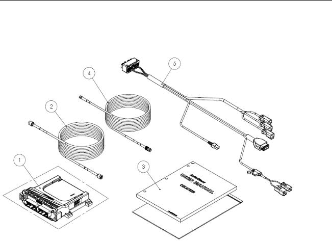
GeoSteer CDMA
This version is used primarily in North America. It has a CDMA modem installed in the GeoSteer control unit that can be used for remote diagnostics and NTRIP correction services.
Figure 1-2 GeoSteer CDMA
Table 1-1 GeoSteer CDMA Breakdown
Item |
Component |
Part Number |
1. |
GeoSteer Assembly - CDMA |
200-0601-XX |
|
|
|
2. |
Cable, GPS Coax |
201-0516-01 |
|
|
|
3. |
Kit Documentation |
200-0593-03 |
|
|
|
4. |
Cable, Cell Modem Coax |
201-0539-02 |
|
|
|
5. |
Harness, Main GeoSteer |
201-0530-03 |
|
|
|
4 |
GeoSteer System |
GeoSteer System Installation Overview
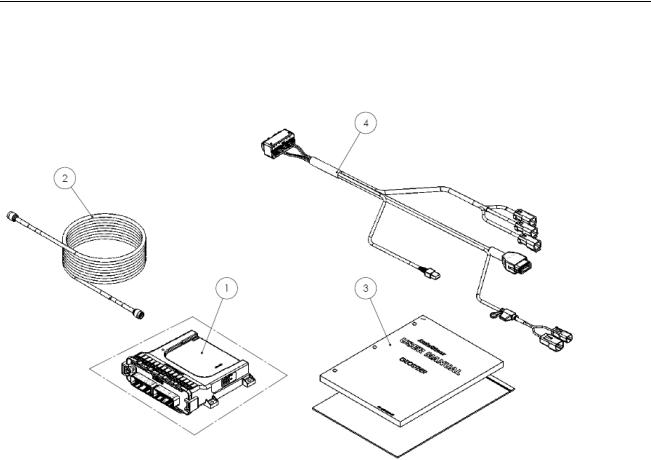
GeoSteer No Cell
This version is used primarily in South America and can be ordered as an option in Australia. There is no cell modem installed inside the GeoSteer control unit.
Figure 1-3 GeoSteer Cell Free
Table 1-2 GeoSteer Cell Free Breakdown
Item |
Component |
Part Number |
1. |
GeoSteer Assembly - No Cell |
200-0617-XX |
|
|
|
2. |
Cable, GPS Coax |
201-0516-01 |
|
|
|
3. |
Kit Documentation |
200-0593-03 |
|
|
|
4. |
Harness, Main GeoSteer |
201-0530-03 |
|
|
|
Operator’s Manual |
5 |
GeoSteer System Installation Overview
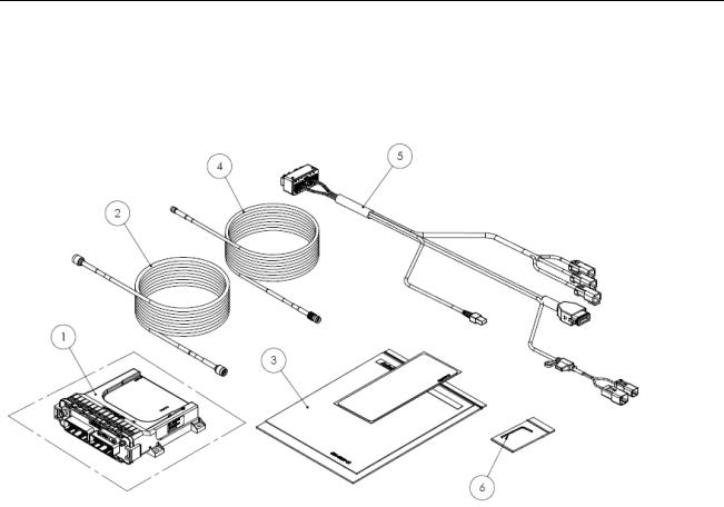
GeoSteer GSM Europe
This version is used primarily in Europe. It has a GSM modem configured to work in the European Union installed in the GeoSteer control unit that can be used for remote diagnostics and NTRIP correction services. The GeoSteer control unit has a SIM card slot that allows the user to easily change SIM cards for a custom data plan if necessary.
Figure 1-4 GeoSteer GSM Europe
Table 1-3 GeoSteer GSM Europe Breakdown
Item |
Component |
Part Number |
1. |
GeoSteer Assembly - GSM Europe |
200-0618-XX |
|
|
|
2. |
Cable, GPS Coax |
201-0516-01 |
|
|
|
3. |
Kit Documentation |
200-0593-05 |
|
|
|
4. |
Cable, Cell Modem Coax |
201-0539-02 |
|
|
|
5. |
Harness, Main GeoSteer |
201-0530-03 |
|
|
|
6. |
Allen Key, 2mm |
805-0006-01 |
|
|
|
6 |
GeoSteer System |
GeoSteer System Installation Overview
GeoSteer GSM Australia
This version is used primarily in Australia. It has a GSM modem configured to work in Australia installed in the GeoSteer control unit that can be used for remote diagnostics and NTRIP correction services. The GeoSteer control unit has a SIM card slot that allows the user to easily change SIM cards for a custom data plan if necessary.
Figure 1-5 GeoSteer GSM Australia
Table 1-4 GeoSteer GSM Australia Breakdown
Item |
|
|
Component |
|
Part Number |
1. |
|
|
GeoSteer Assembly - GSM |
|
200-0619-XX |
|
|
Australia |
|
||
|
|
|
|
|
|
|
|
|
|
|
|
2. |
|
|
Cable, GPS Coax |
201-0516-01 |
|
|
|
|
|
|
|
3. |
|
|
Kit Documentation |
200-0593-03 |
|
|
|
|
|
|
|
4. |
|
|
Cable, Cell Modem Coax |
201-0539-02 |
|
|
|
|
|
|
|
5. |
|
|
Harness, Main GeoSteer |
201-0530-03 |
|
|
|
|
|
|
|
6. |
|
|
Allen Key, 2mm |
805-0006-01 |
|
|
|
|
|
|
|
Operator’s Manual |
7 |
GeoSteer System Installation Overview
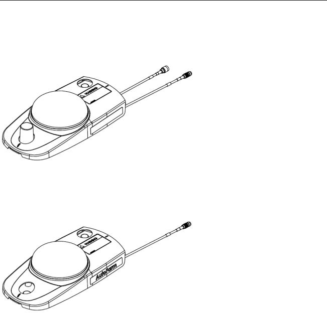
GeoDock Pro
The GeoDock Pro is the roof mounted piece of the GeoSteer system that contains the GPS Antenna and Cell Modem antenna. The GeoDock Pro houses the optional GS-900 or GS-450 Radio Modems or the GS-OmniSTAR Demodulator when they are installed.
Figure 1-6 GeoDock Pro
GeoDock Pro – No Cell
This version of GeoDock is the same as the GeoDock Pro except the assembly does not have a Cell Modem Antenna or coax connector installed on it. This version is ordered with kits that do not come with a Cell Modem.
Figure 1-7 GeoDock Pro - No Cell
3 Vehicle Installation Kits
The GeoSteer system is designed to be compatible with many makes and models of vehicles available in today’s agricultural market. GeoSteer is brand neutral and can be installed on any manufacturer’s vehicle including AGCO, Ag Chem, Case, Challenger, Fendt, John Deere, New Holland, Massey Ferguson, and many others. The GeoSteer system is also capable of being installed on a variety of platforms including articulated tractors, combines, MFWD and standard front axle tractors, floaters, sprayers, swathers, track tractors, and others. The same user interface can be used on all vehicles, regardless of the make or model, making it easy for drivers to become familiar with the controls even if the system is installed on multiple vehicle types.
To make installations simple and reliable, many vehicle-specific installation kits have been designed to fit on each individual make and model. These kits are available for vehicles that come from the factory with a factory installed steering system (ex. Steer Ready, CAN Bus, or ISO Ready) as well as options for those vehicles that need a complete steering kit installed. Even if there is not a vehicle-specific kit available for the vehicle, properly trained installers can often use a custom installation kit to
8 |
GeoSteer System |

Accessing AutoSteer Setup Screens
connect the GeoSteer system to the vehicle. Specific instructions for the vehicle installation kits are provided with the installation kits. Refer to those instructions when installing the vehicle kit.
Note: The list of supported vehicle-specific kits is always being expanded. Contact your AutoSteer dealer for the latest list of vehicle-specific installation kits to see if the vehicle being installed on has a released kit.
4 Accessory Kits
The GeoSteer system is compatible with optional accessory kits that can be ordered and installed to provide additional features and capabilities. The primarily reason to install an accessory kit is to provide a radio modem link with a Base Station or an OmniSTAR demodulator for OmniSTAR corrections. These accessories are not required for all installations and some are not available in all locations. Order only the kits that are required to provide the accuracy level and communication needs required for the installation. The accessory kits available at the time of this writing are:
•GS-900NA (PN 200-0652-01) – 900 MHz radio modem for North America
•GS-900AU (PN 200-0652-02) – 900 MHz radio modem for Australia
•GS-OmniSTAR (PN 200-0653-01) – OmniSTAR demodulator for world
•GS-410 (PN 200-0667-03) – 406-430 MHz radio modem for world
•GS-430 (PN 200-0667-02) – 430-450 MHz radio modem for world
•GS-450 (PN 200-0667-01) – 450-470 MHz radio modem for world
•Remote Engage Foot Switch (PN 200-0458-01) – Remote Engage foot switch that can be attached to the GeoSteer Main Harness to allow the user to start and stop AutoSteer with a foot switch
Note: The list of accessory kits is always being expanded. Contact your AutoSteer dealer for the latest list of accessory kits.
Specific installation instructions for each accessory kit are provided with the kits themselves. Refer to those instructions when installing the accessory kits
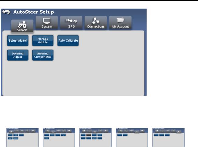
Accessing AutoSteer Setup Screens
The GeoSteer system adds GPS positioning and vehicle steering control to compliment the features of your Display. The settings, configuration options, and monitoring features for the GPS and vehicle communications are kept separate from the Display controls. To access them in a GeoSteer system navigate to the AutoSteer Setup screens from the Display. If changes need to be made to the GPS functionality or to move the system to a different vehicle profile, the user will need to manage those options in the AutoSteer Setup screen.
Your Display Operator’s Manual will provide instructions on navigating to the AutoSteer Setup page. Please refer to that document for those instructions. Figure 1-1 shows the AutoSteer Setup opening screen when it is first accessed from the Display.
Operator’s Manual |
9 |
Transferring GeoSteer from Vehicle to Vehicle
Figure 1-8 AutoSteer Setup Opening Screen
The five folder tabs along the top of the screen separate the GeoSteer configuration and monitoring functions into sub groups to simplify management. The five tabs and the options for each are shown below:
VEHICLE |
SYSTEM |
GPS |
CONNECTIONS |
MY ACCOUNT |
Setup Wizard |
System Health |
RTK |
Cell Modem |
Call Support |
Manage Vehicles |
Manage Settings |
OmniSTAR |
External Radio |
Details |
Auto Calibrate |
Accessories |
WAAS/EGNOS |
|
Feature Code |
Steering Adjust |
Technician |
Precision Settings |
|
|
Steering Components |
Software Upgrade |
NTRIP |
|
|
|
|
Planning Tools |
|
|
|
|
GPS Diagnostics |
|
|
|
|
NMEA Out |
|
|
Each of these tabs is described in detail in the following chapters. For more information about each feature shown above, refer to the corresponding chapter.
Transferring GeoSteer from Vehicle to Vehicle
The GeoSteer system is designed to be easily transferred from vehicle to vehicle. Specific vehicle kits are available that can be installed on each vehicle so that only the Display, GeoSteer Control Unit, and GeoDock need to be transferred from vehicle to vehicle. Each vehicle that the GeoSteer system is to be transferred to should have the Display Harness, Power Harnesses, Vehicle Harnesses, and GeoDock Harnesses already preinstalled. Contact your AutoSteer dealer for information about obtaining and installing additional vehicle specific kits. Use the instructions in the section to transfer the GeoSteer system from one vehicle to another.
10 |
GeoSteer System |
Transferring GeoSteer from Vehicle to Vehicle
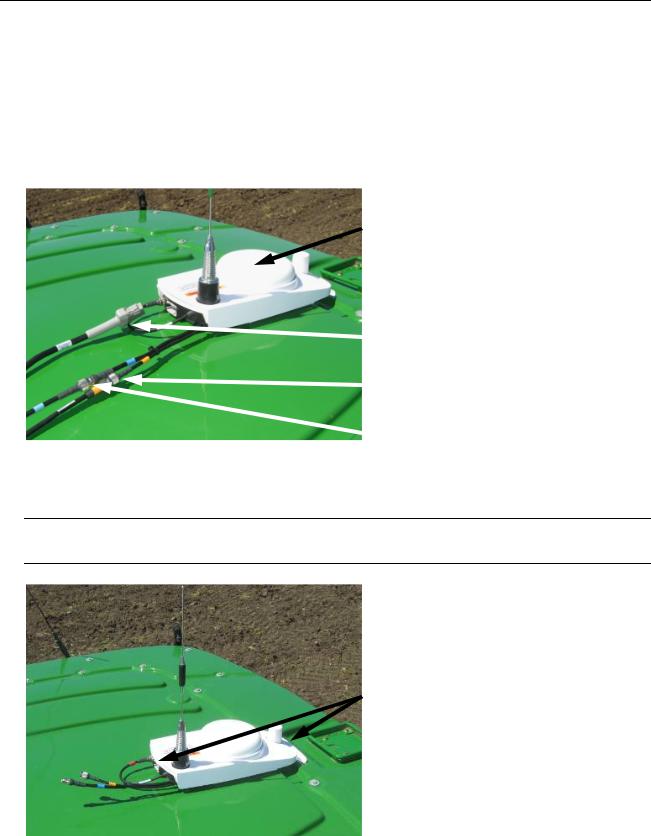
Removing the GeoSteer System from a Vehicle
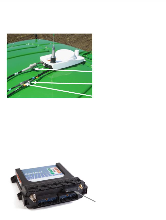
1.Locate the GeoDock on the roof of the vehicle.
2.Disconnect the GPS Coax (Blue) by splitting the TNC Connectors shown.
3.If the GeoDock has a Cell Modem Antenna, disconnect the Cell Modem Antenna Coax (Orange) by splitting the TNC Connectors shown.
4.If the GeoDock has an optional GS-900, GS-450, or GS-OmniSTAR Demodulator, disconnect the 12-pin Power/Data Connector shown.
Figure 1-9 Locate GeoDock and GeoDock Connections
GeoDock
Optional GS-900, GS-450, or GS-OmniSTAR
Demodulator Power/Data Connector
Cell Modem Connector (Orange) (if Applicable)
GPS Coax Connector (Blue)
5.Secure the cable connections left on the cab of the vehicle and protect them from dirt/moisture.
6.Carefully pry the magnetically attached GeoDock from the GeoDock Mounting Bracket.
Note: Only pry up on the GeoDock from the metal lip on the front or back of the GeoDock. Never pry the GeoDock using the plastic cover or by pulling on the coax cables coming out of the back. This can damage the unit.
Pry up from these Points Only
Operator’s Manual |
11 |
Transferring GeoSteer from Vehicle to Vehicle
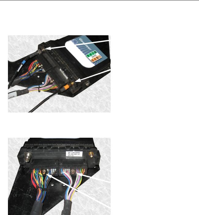
7.Locate the GeoSteer Control Unit on the vehicle.
8.Disconnect the GPS Coax (Blue) TNC Connector from the GeoSteer Control Unit.
9.If the GeoDock has a Cell Modem connection, disconnect the Cell Modem (Orange) SMA Connector from the GeoSteer Unit.
Figure 1-10 Locate GeoSteer Control Unit on Vehicle
TNC GPS Coax (Blue) Connector
SMA Cell Modem Coax (Orange) Connector (if equipped
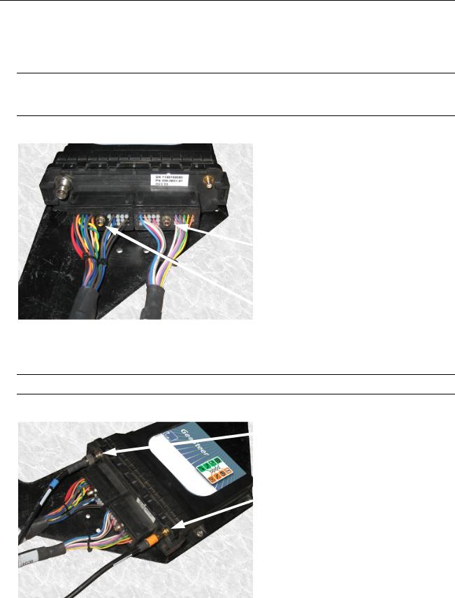
10.Use a 1/4 inch nut driver to remove the GeoSteer Main Cable Harness connector from the GeoSteer Control Unit.
11.Use a 1/4 inch nut driver to remove the Vehicle Specific Cable Harness (if present) from the GeoSteer Control Unit.
Figure 1-11 Disconnect GeoSteer Control Unit Harnesses
Vehicle Specific Cable Harness Connector
(if Installed)
GeoSteer Main Cable Harness Connector
12 |
GeoSteer System |
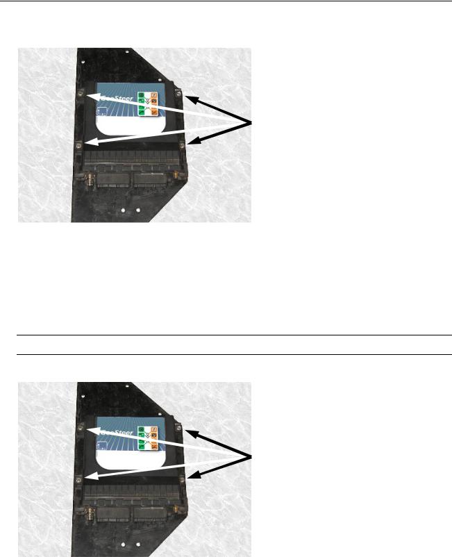
Transferring GeoSteer from Vehicle to Vehicle
12.Remove the four 8-32 x 1/2 Hex Screws using a 1/4 inch nut driver. This releases the GeoSteer Control Unit from the vehicle mounting bracket so it can be moved to another vehicle.
Figure 1-12 Remove Screws Holding GeoSteer Control Unit
Remove the Four Screws
13. Remove the Display from the cab using the instructions provided in the Display Operator’s Manual.
Installing the GeoSteer System on to Vehicle
1.Install the Display in the cab using the instructions provided in the Display Operator’s Manual.
2.Attach the GeoSteer Control Unit to the mounting bracket with four 8-32 x 1/2 Hex Screws. Tighten the screws using a 1/4 inch nut driver.
Note: Do not over tighten the screws.
Figure 1-13 Attach GeoSteer Control Unit with Screws
Attach GeoSteer Control Unit with Four Screws
Operator’s Manual |
13 |
Transferring GeoSteer from Vehicle to Vehicle
3.Attach the GeoSteer Main Cable Harness connector to the left side connector on the GeoSteer Control Unit. Match the Yellow dots on the harness to the GeoSteer Control Unit Connector. Use a 1/4 inch nut driver to tighten the connector.
4.Attach the Vehicle Specific Cable Harness (if required) to the right side connector on the GeoSteer Control Unit. Match the White dots on the harness to the GeoSteer Control Unit Connector. Use a 1/4 inch nut driver to tighten the connectors.
Note: Both connectors are keyed so they will only attach the proper side of the GeoSteer Control Unit and in one orientation. The connectors should slide easily onto the receptacle. If they do not slide easily, try a different position. Do not force the connector into the receptacle as this could damage the connectors.
Figure 1-14 Attach GeoSteer Control Unit Harnesses
Vehicle Specific Cable Harness Connector
(if Required)
GeoSteer Main Cable Harness Connector
5.Attach the GPS Coax (Blue) TNC Connector to the GeoSteer Control Unit.
6.If the GeoDock has a Cell Modem connection, attach the Cell Modem (Orange) SMA Connector from the GeoSteer Unit.
Note: Hand tighten the Coax connectors only. Do not use a tool to tighten as this may damage the connectors.
Figure 1-15 Attach Coax Connectors
TNC GPS Coax (Blue) Connector
SMA Cell Modem Coax (Orange) Connector (if equipped
14 |
GeoSteer System |

Transferring GeoSteer from Vehicle to Vehicle
7.Locate the GeoDock Mounting Plate on top of the cab.
Figure 1-16 GeoDock Mounting Plate
8.Attach the GeoDock to the mounting plate taking care to match the mounting tabs on the GeoDock with the tabs on the mounting plate.
Figure 1-17 Match Tabs on GeoDock to Mounting Plate
Operator’s Manual |
15 |
Changing SIM Card in GeoSteer
9.Attach the GPS Coax (Blue) TNC Connector to the connector on the GeoDock.
10.If the GeoDock has a Cell Modem Antenna, attach the Cell Modem Antenna Coax (Orange) TNC Connector to the connector on the GeoDock.
11.If the GeoDock has an optional GS-900, GS-450, or GS-OmniSTAR Demodulator, connect the 12-pin Power/Data Connector to the back of the radio modem or demodulator.
Figure 1-18 Locate GeoDock and GeoDock Connections
Optional GS-900, GS-450, or GS-OmniSTAR
Demodulator Power/Data Connector
Cell Modem Connector (Orange) (if Applicable)
GPS Coax Connector (Blue)
12.Power up the GeoSteer system and navigate to the AutoSteer Setup screen. Use the Manage Vehicles button to select the activate the vehicle that the GeoSteer system has been installed on. Refer to the Manage Vehicle section on Page 45 for information on setting the active vehicle.
Changing SIM Card in GeoSteer
The GSM Cell Modem versions of the GeoSteer Control Unit have an external SIM card slot that allows the user to change the SIM card for NTRIP usage. This SIM slot is not found on CDMA Cell Modem versions of the GeoSteer Control Unit. This section provides the instructions to change the SIM card if that becomes necessary.
1.Locate the SIM Card slot on the cable connector side of the GeoSteer Control Unit.
Figure 1-19 SIM Card Slot
SIM Card Slot
16 |
GeoSteer System |
 Loading...