


 Loading...
IntellislopeTM Tile Plow Control
System
Operator Manual
Firmware Version 5.2
PN 4003501-ENG_C
COPYRIGHT © 2014
AG LEADER TECHNOLOGY
Ames, Iowa
All Rights Reserved

Table of Contents |
|
Installation |
|
Components and Identification ................................................................................. |
1 |
Display ................................................................................................................ |
1 |
Plow Harness ...................................................................................................... |
1 |
Water Management Module................................................................................ |
2 |
GPS ............................................................................................................... |
3 |
GPS Receiver Configuration ............................................................................... |
3 |
Check Intellislope Unlock ......................................................................................... |
3 |
Create Survey Configuration |
|
About Surveying ....................................................................................................... |
5 |
Configuration Wizard ................................................................................................ |
5 |
Create Tile Configuration |
|
Configuration Wizard ................................................................................................ |
7 |
Setup Tile Controller |
|
Configuration Setup.................................................................................................. |
9 |
Implement Offsets .................................................................................................... |
9 |
Water Management ................................................................................................ |
10 |
Ongoing Pitch Zero Adjustment.............................................................................. |
11 |
Rule of Adjustments .......................................................................................... |
12 |
Hydraulic Pressure and Hose Hookup ................................................................... |
13 |
Roll Calibration ....................................................................................................... |
14 |
Pitch Calibration ..................................................................................................... |
14 |
Look-Ahead Distance ............................................................................................. |
15 |
Antenna Offsets...................................................................................................... |
15 |
Survey |
|
About Surveying ..................................................................................................... |
17 |
Surveying With a Vehicle (Not Plow)...................................................................... |
17 |
Surveying with Plow ............................................................................................... |
18 |
Managing Surveys.................................................................................................. |
20 |
AutoTile |
|
Operating Modes .................................................................................................... |
21 |
ONTENTSC OF ABLET
iii

Installing with AutoTile ........................................................................................... |
21 |
Target Profile Design ............................................................................................. |
22 |
Switch Start Button ................................................................................................ |
22 |
Reverse Outlet Command ..................................................................................... |
23 |
Adjusting Profile to allow Tiling .............................................................................. |
24 |
Tile Type ................................................................................................................ |
25 |
Select Tile Product................................................................................................. |
25 |
Creating Tile Products ...................................................................................... |
25 |
Start Depth Message ............................................................................................. |
26 |
AutoTile in Process ................................................................................................ |
27 |
Grade Control |
|
About Grade Control.............................................................................................. |
31 |
Running Grade Control.......................................................................................... |
31 |
Pitch Control |
|
About Pitch Control................................................................................................ |
35 |
Running Pitch Control............................................................................................ |
35 |
Diagnostics |
|
Devices .................................................................................................................. |
37 |
GPS ....................................................................................................................... |
37 |
Lessons Learned and Pitfalls to Avoid................................................................... |
38 |
Extreme Soil Conditions ................................................................................... |
38 |
Tractor Effects .................................................................................................. |
38 |
Low Hydraulic Pressure.................................................................................... |
39 |
Failure to Float the Three-point Hitch or Wheel Frame .................................... |
39 |
Operating Too Shallow ..................................................................................... |
39 |
Driving Too Fast ............................................................................................... |
39 |
Obstructions ..................................................................................................... |
39 |
Detuned Configuration Parameters .................................................................. |
39 |
GPS Interruptions ............................................................................................. |
40 |
Defective Components ..................................................................................... |
40 |
iv |
Firmware Version 5.2 |
INSTALLATION
COMPONENTS AND IDENTIFICATION
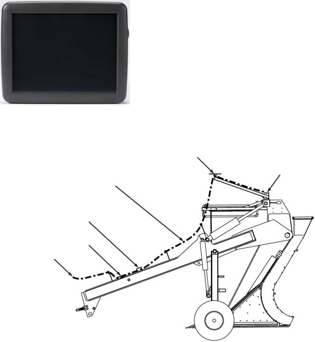
DISPLAY
The AgLeader Integra display will mount in the cab. Use the
provided cables in the cable kit to install power direct to the battery terminals, routing them out of the way, and clear of moving parts. Use the provided zip ties, to secure the cables. If you have excess cabling, coil excess cables in an area that will not get caught on moving parts. A RAM mount is provided to mount the display in the cab, and allows for flexibility to install where windows and gauges are not obstructed.
Locate the 4001979-3 cable, and route this toward the back of the tractor. For most front wheel assist tractors this should reach to the plow harness that is installed on the tile plow. If you need additional length, extension cables are available
from your dealer in 6 and 12 ft lengths for 4-Wheel drive tractors.
PLOW HARNESS
GPS Antenna Location
Module Location
Cable Routing
Pitch Valves
Wheel Depth Valves
Tractor Connection
Figure 1
Locate cable PN 4003415. This will be mounted on the plow, with the single round cable connector at the hitch. There are 2 weather pack connectors that will connect to the Proportional valve. If you cannot route the cables to make these ends work, extensions can be ordered by your dealer to make the
1
connections. Route the cable as shown below to ensure that moving parts do not pinch cables, extensions, or adapters.
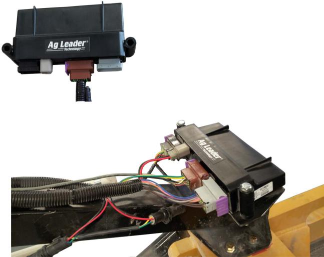
WATER MANAGEMENT MODULE
The module was designed to be oriented so the cable
connections face the tractor. This is so the sensors are oriented correctly, and work as they were designed. Use the provided Module adapter plate and hardware to secure the module to the plow in the location as shown on the previous page. The label should also face Up when installing.
Make sure that you color match the connections from the Harness to the module and you don’t force the connections, this can damage electrical pins. The round connections on the harness will be used to power the GPS receiver. The 2 large, and 1 small square connections will connect to the module. The Brown connector will be used for the GPS signal input.
2 |
Firmware Version 5.2 |
INSTALLATION
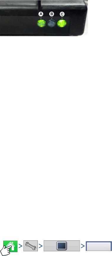
LED (A) and (B)
•Off - CAN BUS is idle
•Flashing Green - CAN BUS communicating
•Blinking Yellow – Active BUS error when other devices are transmitting/receiving
•Solid Yellow – Passive BUS error when no other devices are acknowledging
•Solid Red – BUS Off
LED (C)
•Off – no power
•Solid Red – Low voltage
•Solid Green – Good power
GPS
Make sure the GPS receiver is mounted over the top of the cutting shear as shown in Figure 1 on
.page 1. There will be 2 cables that will connect the GPS receiver to the module, one will be specific to your specific GPS receiver.
Double check to make sure that all connections are made and snug, and all cables are secured and not routed in areas that will be pinched.
GPS RECEIVER CONFIGURATION
For Intellislope to receive GPS information from the receiver, the receiver needs to be sending out NMEA GGA, VTG, and GSA sentences. NMEA is a standardized output that virtually every GPS receiver supports. There are different BAUD rates, hertz, and types of messages that the GPS receiver can send out. Your receiver must be configured to send out the message at either 19,200 BAUD or 38,400 BAUD. The receiver must also be configured to run at 5 or 10 Hz for GGA and VTG, and 1 Hz for GSA. The only sentences Intellislope needs are GGA, VTG, and GSA. Please turn off all other messages.
If your GPS antenna has an internal roll correction applied when transmitting the Lat/Long data, you must 0 out the antenna height while connected to the WMC module. The WMC module has its own Roll correction sensor to compensate for the side roll of the plow. If the GPS receiver is sending this message as well, the value will be 2 times greater than it should be resulting in degraded performance.
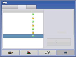
CHECK INTELLISLOPE UNLOCK
Features
Press: Home button > Setup (wrench) button > Display button > Features tab
3
Console Setup
General Display |
Features |
Advanced |
|
Feature |
|
Status |
Feature Description: |
Automatic Swath Control |
Enabled |
Enables Intellislope tile mode. |
|
|
|||
Multiple Product |
|
Off |
|
Norac UC5 Interface |
|
Enabled |
|
Fan Frame - Feed Gate Control |
Off |
|
|
ISOBUS Virtual Terminal |
Enabled |
|
|
HARDI Sprayer |
|
Off |
|
Intellislope Tiling |
|
Enabled |
|
Unlock
The Features Tab is where you can enter unlock codes. Unlock codes are unique to the serial number of each display and the feature registration number. You must supply these numbers to your dealer when
purchasing any unlock codes. Press  to enter
the unlock code and Press  to enable the feature.
4 |
Firmware Version 5.2 |

CREATE SURVEY CONFIGURATION
ABOUT SURVEYING
•requires driving over the path where tile will be placed
•required by AutoTile but not by Grade Control or Pitch Control
•can be done right before laying tile or well in advance, provided your RTK base station has been surveyed in, and is placed in the same location for surveying and installation.
•can be done using tiling equipment (using the tiling configuration) or a separate vehicle (using the surveying configuration)
•can use either Versa or Ag Leader Integra display (tiling requires an Ag Leader Integra display)
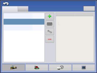
CONFIGURATION WIZARD
Configuration |
Surveying |
Press: Home button > Setup (wrench) button > Configuration (tractor) button > Configuration tab > Add
(+) button > Surveying button
A wizard will then guide you through the process of creating a configuration using the following steps:
1. Select Vehicle
Select an existing vehicle from the drop-down menu or create a new vehicle.
Press  and create a new vehicle with the Vehicle Setup Wizard.
-Vehicle Wizard - input the following information:
a.vehicle type
b.make and model
c.distance from rear axle to rear drawbar, rear lift arms, front lift arms (not necessary for surveying operation but can be useful if vehicle is used for other operations)
d.vehicle name
Press  to edit offsets listed on screen:
-Antenna Location from Rear Axle
-Antenna Location from Centerline
-Antenna Height from Ground (Very important that this measurement is correct for accurate tile placement)
-Rear Drawbar
-Rear Lift Arms
-Front Lift Arms
Press  to continue.
2. Select Speed Source
Select Primary and Backup Source (Display GPS, Auxiliary Device, GPS via WM Control)
5
3. Enter Configuration Name
A suggested name for the configuration appears. If desired, Press  to enter a different name for your configuration. Press
  when complete.
Configuration Setup
Configuration |
Product |
Equipment |
Surveying |
Equipment |
Name |
|
|
|
Quad 500 |
Vehicle |
Quad 500 |
|
|
Coverage
Tiling
JD 8310R, SoilMax GoldDigger
The complete configuration should now appear on the Configuration Setup screen and is now able to be selected when starting a new field operation.
6 |
Firmware Version 5.2 |
CREATE TILE CONFIGURATION
CONFIGURATION WIZARD
Configuration |
Tiling |
Press: Home button > Setup (wrench) button > Configuration (tractor) button > Configuration tab > Add
(+) button > Tiling button
A wizard will then guide you through the process of creating a configuration using the following steps:
1. Select Vehicle
Select an existing vehicle from the drop-down menu or create a new vehicle.
Press  and create a new vehicle with the Vehicle Setup Wizard.
-Vehicle Wizard - input the following information:
a.vehicle type
b.make and model
c.distance from rear axle to rear drawbar, rear lift arms, front lift arms (not necessary for surveying operation but can be useful if vehicle is used for other operations)
d.vehicle name
Press  to edit offsets listed on screen:
-Antenna Location from Rear Axle
-Antenna Location from Centerline
-Antenna Height from Ground (Very important that this measurement is correct for accurate tile placement)
-Rear Drawbar
-Rear Lift Arms
-Front Lift Arms
Press  to continue.
2. Select Implement
Select an existing implement from the drop-down menu or create a new implement.
Press  and create a new implement with the Implement Setup Wizard.
-Implement Wizard - input the following information:
a.make and model
b.implement attachment type (Rear Drawbar or Rear Lift Arms)
c.controller WM Control
d.GPS Antenna Offset
•Antenna Location from Hitch Point
•Antenna Location from Ground (measurement must be taken with the implement raised all the way up in transport position.)
•Antenna to Plow Base (when collecting surveys with this configuration, the plow must be in the same position for each survey to collect accurate soil elevation)
7
•Antenna to Tip (Horizontal: an example is if the plow tip is 24 inches ahead of antenna, you would enter 24 in front)
•Antenna Location from Centerline e. implement name
Press  to continue.
3. Select Speed Source
Select Primary and Backup Source (Display GPS, Auxiliary Device, GPS via WM Control)
4. Enter Configuration Name
A suggested name for the configuration appears. If desired, Press  to enter a different name for your configuration. Press
  when complete.
The complete configuration should now appear on the Configuration Setup screen and is now able to be selected when starting a new Field Operation
8 |
Firmware Version 5.2 |

SETUP TILE CONTROLLER
CONFIGURATION SETUP
Configuration
Select Your Specific
Configuration
Press: Home button > Setup (wrench) button > Configuration (tractor) button > Configuration tab > Your Specific Configuration > Setup (wrench) button
Note: Use the Manage Equipment button to view a list of specific vehicles and implements.
IMPLEMENT OFFSETS
Configuration Setup
Vehicle
JD 8530
Vehicle |
|
|
|
|
Offsets |
Implement: SoilMax Golddigger |
Controller: tile |
|
|
|
ul Swath: |
32808 ft |
Serial Number |
Unassigned |
|
Sections: |
1 |
|
|
|
|
|
|
|
Speed
Input
Equipment |
Offsets |
Controller |
|
Settings |
|||
Settings |
|
||
|
|
Press |
Vehicle Offsets |
to adjust vehicle offsets. |
Press: |
Speed Input |
to modify source of speed. |
Press |
Offsets |
to adjust plow offsets |
that were setup when creating configuration.
Antenna to Tip is the horizontal measurement of the tip to the Antenna. An example is if the tip is 24 inches front of the Antenna, you would enter 24 in. and Front (as shown).
9
WATER MANAGEMENT
Select Your Specific
Configuration Configuration
Controller |
|
Settings |
Control |
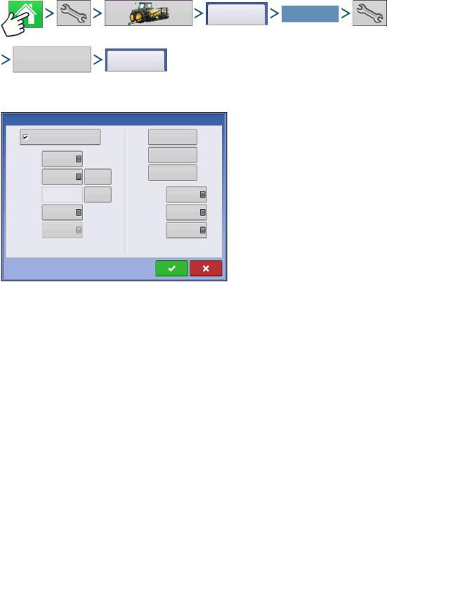
Press: Home button > Setup (wrench) button > Configuration (tractor) button > Configuration tab > Your Specific Configuration > Setup (wrench) button > Controller Settings button > Control tab
Pitch Plow |
|
|
Verify |
|
|
|
Control |
||
|
|
|
||
|
|
|
Calibrate |
|
Pitch Gain |
0 |
|
Roll |
|
|
|
Reset to |
Calibrate |
|
Pitch Zero |
0 |
Pitch |
||
Default |
||||
|
|
|
Pitch Plow check box: check this box only if the machine is a pitch plow (also called cantilever).
If this box is not checked, Pitch Gain, Pitch Zero, Suggested Calibration, and Start Compensation boxes will be grayed out and unavailable.
Suggested |
350 |
Set as |
Up Valve |
0 |
This setting effects the operation of Intellislope and it |
|
Calibration |
Pitch Zero |
Threshold |
is crucial that it is set correctly. When check box is |
|||
|
|
|||||
|
|
checked, it indicates that the machine being |
||||
Compensation |
0 % |
|
Threshold |
0 |
||
Start |
|
|
Down Valve |
|
|
|
GPS-Only |
0 |
|
Look-Ahead |
0 in |
controlled is a pitch plow and the elevation of its |
|
Gain |
|
Distance |
cutting edge is determined by the pitch of the plow. |
|||
|
|
|
||||
|
|
|
|
This must be un-checked if the machine is not a pitch plow, such as a parallel linkage plow, trencher, scraper or pan, where the elevation of the cutting edge of the machine is directly effected by the
hydraulic cylinder displacement. In this case the GPS receiver must move with the cutting edge for proper control.
The following table summarizes the interaction between the pitch plow setting and adjustments on the Performance Setup screen
.
Adjustment |
Pitch Plow Checked |
Pitch Plow Un-checked |
Comments |
|
|
|
|
Pitch Gain |
Yes |
No effect |
Pitch Gain only has effect |
|
|
|
when the system is controlling |
|
|
|
pitch, and thus only when |
|
|
|
configured as a pitch plow. |
|
|
|
|
Look Ahead Distance |
Yes |
No effect |
Look Ahead Distance only has |
|
|
|
effect when the system is |
|
|
|
using pitch to control |
|
|
|
elevation, and thus only has |
|
|
|
effect when configured as a |
|
|
|
pitch plow. |
|
|
|
|
GPS-Only Gain |
No effect |
Yes |
GPS-Only Gain only has effect |
|
|
|
when the system is directly |
|
|
|
controlling elevation in |
|
|
|
systems where the hydraulic |
|
|
|
cylinder directly controls |
|
|
|
elevation (not a pitch plow). |
|
|
|
|
10 |
Firmware Version 5.2 |
Loading...