

Page 1

User’s Guide
Publication number E2625-97003
March 2002
For Safety information and Regulatory information, see the pages at the end of
this manual.
© Copyright Agilent Technologies 1999-2002
All Rights Reserved
Infiniium Option 100 and
E2625A Telecommunications
Mask Template Kit
Page 2

In This Book
This Telecommunications Mask Template Kit User’s Guide contains the
following information:
Introduction to Option 100 and E2625A Telecommunications Mask
Template Kit
Chapter 1 introduces specific product information about the Mask Template
Kit. It also discusses the recommended oscilloscope configuration, and shows
an overview of the Mask Test Setup dialog box.
Getting Started and Using Masks
C h a p t e r 2 d e s c r i b e s M a s k Te s t i n g a n d s h o w s y o u wa ys t o u s e t h e st a n d a r d m a s k s
to verify compliance of your instrument waveforms.
Standard Masks
Chapter 3 lists file names for the standard masks in the Telecommunications
Mask Template Kit, along with line impedances and bit rates. The templates
for each standard mask are also shown.
ii
Page 3

Contents
1 Introduction to Option 100 and E2625A Telecommunications
Mask Template Kit
Adding Option 100 to an existing Infiniium Oscilloscope 1-2
Supplied items 1-3
Recommended accessories 1-3
What not to do 1-3
Oscilloscope models 1-4
To access the Mask Test Setup dialog box 1-5
Overview of the Mask Test Setup dialog box 1-6
2 Getting Started and Using Masks
Introduction to Mask Testing 2-2
Make a copy of the Mask Test disk 2-3
To install the Standard Masks 2-4
To calibrate the oscilloscope 2-5
To choose a proper probe for Mask Testing 2-6
To get your waveform on the oscilloscope display 2-7
To enable the Mask Test 2-8
To load a Mask 2-9
To align a Mask to the waveform 2-10
To start and stop the Mask Test 2-11
To understand the Mask Test tab description area 2-12
To run the Mask Test conditionally 2-13
To stop the Mask Test on the first failure 2-14
3Standard Masks
ITU G.703 International Standard Masks 3-4
ANSI T1.102 North American Standard Masks 3-11
FCC Part 68.308 Options A, B, and C Masks 3-17
Pre-Compliance SONET Masks 3-19
IEEE 802.3 Masks 3-21
Contents-1
Page 4

Contents-2
Page 5

1
Introduction to Option 100 and E2625A Telecommunications Mask Template Kit
Page 6

Introduction to Option 100 and E2625A
Telecommunications Mask Template Kit
The Infiniium Oscilloscopes Option 100 Telecommunications Mask
Template Kit includes the materials necessary for you to verify that your
instrument waveforms comply with industry standards. Option 100
provides a quick method for you to certify waveform integrity during
early development and later during manufacturing tests.
This manual helps you use the standard masks supplied with Option 100.
It shows you how to load standard waveform masks into Infiniium
Oscilloscopes and use them to test the compliance of your waveforms.
All of the standard masks supplied are shown in Chapter 3.
Adding Option 100 to an existing Infiniium Oscilloscope
The Op tion 100 Telecommunications Mask Template Kit is orderable as
E2625A for customers who already have an Infiniium Oscilloscope.
1-2
Page 7

Introduction to Option 100 and E2625A Telecommunications Mask Template Kit
Supplied items
Supplied items
The Option 100 Telecommunications Mask Template Kit contains the
following items:
Mask Template
Kit Item
Floppy disk Mask template library floppy disk E2626A
Adapter 100/110/120
Adapter cable Bantam (m) to Siemens (f) adapter cable E2623A
Adapter 75
Adapter cable Dual-bantam (f) to RJ48C (m) adapter cable E2624A
Adapter/coupler RJ48C (f) to RJ48C (f) E2627A
Adapter Bantam (m) to BNC (f); for system verification of
Adapter BNC (m) to BNC (f) 50-to-75 ohm adapter; for
Cable BNC (m) to BNC (m) cable; 30 cm long 8120-1838
Storage case Hard-shell case for storage of all kit accessories E2625-45501
Description Separately Orderable
Ω differential impedance adapter
with bantam (f) connector, bantam (m) to
Siemens (f) adapter cable
Ω single-ended impedance adapter with
BNC (f) connector
E2621A adapter and Infiniium oscilloscope
system verification of E2622A adapter and Infiniium
oscilloscope
Agilent Part Number
E2621A
E2622A
E2628A
E2629A
Recommended accessories
Other Agilent accessories recommended for use in mask testing include:
Agilent Part
Number
E2630A Patch cable Bantam (m) to bantam (m) patch cable
E2632A Patch cable Siemens (m) to Siemens (m) patch cable
Accessory Item Description
What not to do
You should not use the Mask Test master disk for daily use. Instead, you
should use a copy of the master disk, as described in Chapter 2.
1-3
Page 8

Introduction to Option 100 and E2625A Telecommunications Mask Template Kit
Oscilloscope models
Oscilloscope models
You can use the Telecommunications Mask Template Kit with these
Infiniium Oscilloscopes:
Agilent Model Channels Bandwidth Sample Rate Memory Depth
1
54810
54815
54820
54825
54835
54845
54846
54830
54831
54832
1
1
1
1
1
1
2
2
2
2 500 MHz 1 GSa/s 32k
4 500 MHz 1 GSa/s 32k
2 500 MHz 2 GSa/s 32k
4 500 MHz 2 GSa/s 32k
4 1.5 GHz 2 GSa/s — 4 ch
4 GSa/s — 2 ch
4 1.5 GHz 4 GSa/s — 4 ch
8 GSa/s — 2 ch
4 2.25 GHz 4 GSa/s — 4 ch
8 GSa/s — 2 ch
2 600 MHz 2 GSa/s — 4 ch
4 GSa/s — 2 ch
4 600 MHz 2 GSa/s — 4 ch
4 GSa/s — 2 ch
4 1 GHz 2 GSa/s — 4 ch
4 GSa/s — 2 ch
32k — 4 ch
64k — 2 ch
32k — 4 ch
64k — 2 ch
32k — 4 ch
64k — 2 ch
2M — 4 ch
4M — 2 ch
2M — 4 ch
4M — 2 ch
2M — 4 ch
4M — 2 ch
1
Requires system software version A.03.00 or later.
2
Requires system software version A.02.00 or later.
1-4
Page 9
Introduction to Option 100 and E2625A Telecommunications Mask Template Kit
To access the Mask Test Setup dialog box
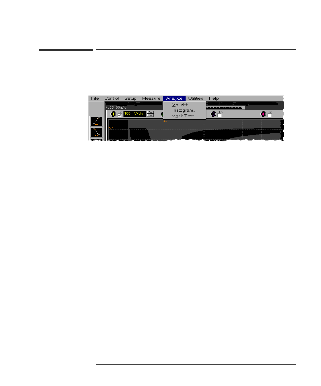
To access the Mask Test Setup dialog box
Select Analyze, then Mask Test... from the oscilloscope main menu, as shown
here, to access the Mask Test Setup dialog box:
1-5
Page 10
Introduction to Option 100 and E2625A Telecommunications Mask Template Kit
Overview of the Mask Test Setup dialog box
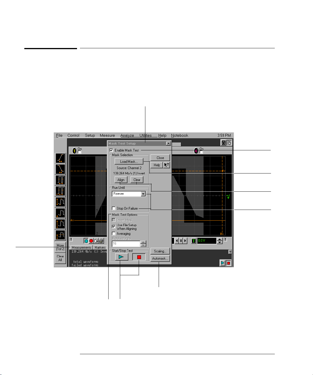
Overview of the Mask Test Setup dialog box
You will use the Mask Test Setup dialog box shown here to load and use
masks with the Infiniium Oscilloscope. Standard masks are shown in
Chapter 3. How to load and use a mask is described in Chapter 2.
Mask Test Setup
Dialog Box
Checkmark to
enable the
Mask Test.
Click to load a
Mask.
A Mask Test tab
will appear
when the
Mask Test
is enabled.
Check options to invert a
mask, use the file setup
when aligning a m ask, or
enable averaging to
reduce noise.
1-6
Click to start
and stop the
Mask Test.
Click to align or
clear a Mask.
Conditionally run
the Mask Test
and stop on the
first failure.
See the Infiniium help system to
use Scaling and Automask.
Page 11

2
Getting Started and Using Masks
Page 12

Getting Started and Using Masks
Telecommunications (telecom) and data communications (datacom)
industries have established standards for equipment manufacturers.
One of these standards defines the electrical parameters for waveforms.
By applying these standards, both telecom and datacom equipment
manufacturers can ensure that their equipment will operate properly
together by first certifying waveform integrity.
To verify waveform integrity during the equipment manufacturing
phase, Infiniium Oscilloscopes have a feature called Mask Testing.
Within seconds, you know whether your equipment’s waveform complies
with the industry standard.
Introduction to Mask Testing
What is a Mask?
A mask is a template that you load into the oscilloscope used during mask
testing. The mask shows the acceptable electrical parameters of a waveform
by defining regions of the oscilloscope display where the waveform must not
intersect. If the waveform crosses the boundary of a region of the mask, it fails
the mask test.
The types of masks that you can use to test waveforms include:
• Industry standard masks
Industry standard masks are included in this Mask Template Kit.
• Automatically generated masks
• User-defined masks
When to use Mask Testing
You should use mask testing whenever your waveform must conform to an
industry standard. You can do mask testing during manufacturing to ensure
that your design meets the requirements of the telecom or datacom industries.
2-2
Page 13

Getting Started and Using Masks
Make a copy of the Mask Test disk
How Infiniium does Mask Testing
When you start the mask test, Infiniium creates a database that has unique
locations for every pixel in the waveform viewing area. Each location in the
database has a 21-bit counter for a maximum count of 2,097,151.
Each time a data point from a channel memory illuminates a pixel in the
wav efor m viewi ng a r ea, th e count er for that pi xel i s incre ment e d. Du r ing ma sk
testing, any data point that illuminates a pixel in the mask violation region
causes a mask test failure.
The oscilloscope’s database continues to build until the oscilloscope stops
acquiring data or until mask testing is deactivated.
The oscilloscope’s database is also used for histogram analysis and color grade
persistence. Refer to the Infiniium help system for detailed information about
these other waveform analysis features.
How to do Mask Testing
The remaining topics in this chapter show you how to do mask testing.
Chapter 3 shows the standard masks supplied in the Mask Template Kit.
Make a copy of the Mask Test disk
A disk containing the stand ard masks is shipped with Infiniium Option 100 and
E2625A. Before you install the Mask Test templates, you should make a copy
of the Mask Test master disk and use the copy of the Mask Test disk for the
installation.
2-3
Page 14
Getting Started and Using Masks
To install the Standard Masks
To install the Standard Masks
Use the copy of the Mask Test disk to install standard masks onto the Infiniium
hard drive. The Mask Test disk contains many of the available standard masks
that you may need to use during mask testing.
1
Insert the copy of the Mask Test disk in the floppy drive.
2 From the oscilloscope main menu, select Analyze, then Mask Test.
3 In the Mask Test Setup dialog box, select the Enable Mask Test control.
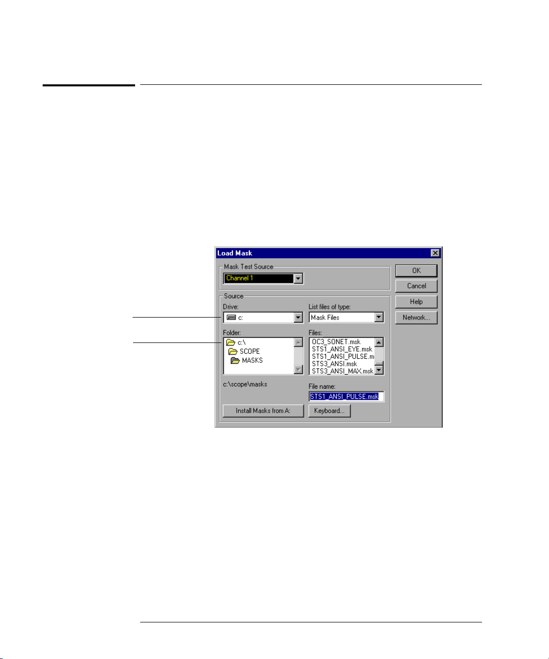
4 In the Mask Test Setup dialog box, click the Load Mask... button.
The Load Mask dialog box will resemble:
This selects the disk
where the masks
are installed.
This selects the
directory where the
masks are installed.
5
Click the Install Masks from A: button.
2-4
Page 15

Getting Started and Using Masks
To calibrate the oscilloscope
To calibrate the oscilloscope
Your Infiniium should be at optimum performance when performing mask
testing. If your Infiniium has not been calibrated in the last year or if the
Calibration ∆Te m p i s gr e a t e r th a n ± 5 °C , yo u sh o u l d r e c a l i b r a te t h e os c i l loscope
before performing a mask test. You can find the Calibration ∆Temp in the
Calibration dialog box by clicking on the Utilities menu and selecting Calibration.
1
Make sure Infiniium has warmed up for at least 30 minutes.
2 From the oscilloscope main menu click Utilities, then Calibration.
3 Make sure that the Cal Memory Protect check box is unchecked.
Cal Memory Protect This option protects the oscilloscope’s calibration factors from
Details When checked, this option displays a list of anything that has failed
4 Click Start.
Infiniium will display additional instructions and guide you through the stepby-step calibration procedure.
accidentally being changed.
during the cal ibration. You can us e the failure informati on to help repair
the oscilloscope.
2-5
Page 16

Getting Started and Using Masks
To choose a proper probe for Mask Testing
To choose a proper probe for Mask Testing
You can use any oscilloscope probe that fits your application. Depending on the
type of waveform you are testing, you may need to use one of the probe adapters.
Calibrating the probe adapter
Depending on the requirements of your Telecom or Datacom industrial
standard, you may need to use the E2622A 75 Ω probe adapter or the E2621A
differential probe adaptor. Before performing a mask test, you should calibrate
the probe adapter using the following instructions:
1
In the Channel Setup dialog box, click the Probes... button.
2 In the Probes Setup dialog box, click the Calibration... button.
3 Follow the step-by-step instructions to calibrate the probe.
2-6
Page 17

Getting Started and Using Masks
To get your waveform on the oscilloscope display
To get your waveform on the oscilloscope display
When doing mask testing, you will try to fit the mask to your waveform. This
is how you will verify whether your waveform meets the acceptable electrical
parameters defined by the standard mask. By having your waveform displayed
on the oscilloscope screen before doing mask testing, when you load and use
the mask, you will know immediately if the waveform passes the mask test.
1
Display the waveform you want to test on the oscilloscope screen.
2 Begin mask testing using a standard mask, as described in the following
topics.
2-7
Page 18

Getting Started and Using Masks
To enable the Mask Test
To enable the Mask Test
1 Click Analyze, then Mask Test to access the Mask Test Setup dialog box.
2 In the Mask Test Setup dialog box, click Enable Mask Test to checkmark
the box.
When enabled, a Mask Test tab appears beneath the waveform viewing area.
Checkmark
to enable t he
Mask Test.
2-8
Page 19

Getting Started and Using Masks
To load a Mask
To load a Mask
1 Click Analyze, then Mask Test to access the Mask Test Setup dialog box.
2 Make sure the mask test is enabled.
3 Click the Load Mask... button.
4 In the Load Mask dialog box, click the Mask Test Source field to select an
oscilloscope channel for the mask test. The active channel is the
default.
5 Click the Drive: field and select the drive where the mask you want to
load is located. In the
List files of type: field, Mask Files will be displayed
by default.
6 To load a standard mask from the Infiniium hard drive, make sure the
Folder: shows c:\scope\masks. Then view the list of standard masks by
scrolling them in the
7 When you find the standard mask that you want to load, double-click
the file in the
Files: field. The mask file name will be entered and
highlighted in the
Chapter 3 lists the standard mask file names and shows the mask waveforms.
Files: field.
File name: field, and Infiniium will load the mask.
2-9
Page 20

Getting Started and Using Masks
To align a Mask to the waveform
To align a Mask to the waveform
1 Access the Mask Test Setup dialog box and make sure the mask test is
enabled.
2 Locate the Use File Setup When Aligning option.
When aligning a mask to the waveform, these settings are used:
• Channel range and offset
• Time base range and position
• Trigger mode and level
• Mask test scaling source, position(s), and delay
You can either use the current oscilloscope settings, or you can use the standard
settings defined in the mask file.
If you want to use the standard settings defined in the mask file,
3
checkmark the
4 If you want to use the current oscilloscope settings, do not checkmark
this box.
Use File Setup When Aligning option.
When aligning a
mask, you can use
the current settings
for the oscilloscope
setup, or use the
standard settings in
the mask file.
5 Click the Align button to align the mask.
2-10
Page 21

Getting Started and Using Masks
To start and stop the Mask Test
To start and stop the Mask Test
1 Access the Mask Test Setup dialog box and make sure the mask test is
enabled.
2 At the bottom of the Mask Test Setup dialog box, locate the start and
stop mask test buttons.
• The green triangle starts the mask test.
• The red square stops the mask test.
Starts mask
test in the
Mask Test
Setup dialog
box.
3
Click the green triangle to start the mask test.
Stops mask test in the Mask
Test Setup dialog box.
Starts/stops mask test
from the Mask Test tab.
When you start a mask test, Infiniium also starts the acquisition system.
2-11
Page 22

Getting Started and Using Masks
To understand the Mask Test tab description area
To understand the Mask Test tab description area
After you have enabled the mask test in the Mask Test Setup dialog box, you
will see a Mask Test tab on the lower left of the oscilloscope screen, beneath
the waveform viewing area. The description area below the Mask Test tab
shows:
• Mask title
• Amplitude specifics (for ANSI T1.102 North American Standard Masks only)
• Total number of waveforms in the duration of the mask test
• Number of failed waveforms in the mask test
• Regions in the mask
• Waveform violations
Mask Test tab
Description area
When any of the ANSI T1.102 North American Standard Masks are loaded, the
Mask Test tab description area will show minimum and maximum amplitude
values. These values are the result of testing for specifics of the standard, and
indicate the upper or lower limit that the standard allows.
2-12
Page 23

Getting Started and Using Masks
To run the Mask Test conditionally
To run the Mask Test conditionally
1 Access the Mask Test Setup dialog box and make sure the mask test is
enabled.
2 Click the Run Until selection arrow to view the options.
a If Stop on Failure is disabled, you can stop the mask test based on the
following conditions:
•Forever
The mask test will run continuously. This is the default selection.
•Number of Waveforms
The mask test will run until the number of waveforms specified has been
acquired. The number of waveforms is from 1 to 1,000,000,000.
•Time
The m as k test wil l r un until t he am ount of t im e specifie d h as elapse d. The
time is in seconds, from 0.1 minute to 1440.0 minutes. The default is 1.0
minute.
b If Stop on Failure is enabled, the first time the waveform crosses the mask
violation region, the mask test will stop. See the next topic.
Click and select how you
want the mask test to run.
Checkmark if you want
the mask test to stop
on the first failure.
3
Select the Run Until option you want to use for the mask test.
2-13
Page 24

Getting Started and Using Masks
To stop the Mask Test on the first failure
To stop the Mask Test on the first failure
1 Access the Mask Test Setup dialog box and make sure the mask test is
enabled.
2 Click Stop On Failure to checkmark the box.
3 Run the mask test.
When the mask test encounters the first failure, the test will stop and the failure
result will be displayed in the Mask Test tab description area.
Analyzing a failure
If your waveform crosses the boundary of the mask violation region, the
waveform cross-over areas will be displayed in red. All waveform locations
displayed in red indicate that the waveform fails the mask test in these areas.
If the waveform just “touches” the boundary, the mask test fails.
Standard masks and the designated violation regions are shown in chapter 3.
When you start the mask test with Stop On Failure enabled, if Infiniium
encounters a failure, the oscilloscope acquisition system will be stopped.
2-14
Page 25

3
Standard Masks
Page 26

Standard Masks
The Infiniium Option 100 and the E2625A Telecommunications Mask
Template Kit disk contains standard masks used by the
telecommunications and data communications industries. These are the
masks you can load into the oscilloscope to test your waveform’s
compliance against industry standards.
To use any of these masks, follow the procedures in chapter 2.
Standard Masks
The types of standard masks include:
• ITU G.703 International Standard Masks
• ANSI T1.102 North American Standard Masks
• FCC Part 68.308 Options A, B, and C Masks
• Pre-Compliance SONET Masks
• IEEE 802.3 Masks
ITU G.703 International Standard Masks
Mask File Name Line Impedance Bit Rate
1544kb_ITU_DS1.msk 100
2Mb_ITU_120.msk 120
2Mb_ITU_75.msk 75 Ω coax 2.048 Mbps
6312kb_ITU_110_DS2.msk 110
6312kb_ITU_75_DS2.msk 75 Ω coax 6.312 Mbps
8Mb_ITU.msk 75 Ω coax 8.448 Mbps
34Mb_ITU.msk 75
44736kb_ITU_DS3.msk 75 Ω coax 44.736 Mbps
140Mb_ITU_0.msk 75 Ω coax 139.264 Mbps
140Mb_ITU_1.msk 75
140Mb_ITU_1_INV.msk 75 Ω coax 139.264 Mbps
155Mb_ITU_0.msk 75 Ω coax 155.520 Mbps
155Mb_ITU_1.msk 75
155Mb_ITU_1_INV.msk 75 Ω coax 155.520 Mbps
3-2
Ω twisted pair 1.544 Mbps
Ω twisted pair 2.048 Mbps
Ω twisted pair 6.312 Mbps
Ω coax 34.368 Mbps
Ω coax 139.264 Mbps
Ω coax 155.520 Mbps
Page 27

ANSI T1.102 North American Standard Masks
Mask File Name Line Impedance Bit Rate
DS1_ANSI.msk 100
DS1A_ANSI.msk 100
DS1C_ANSI.msk 100
DS2_ANSI.msk 110
DS3_ANSI.msk 75
DS4NA_ANSI.msk 75
DS4NA_ANSI_MAX.msk 75
STS1_ANSI_EYE.msk 75
STS1_ANSI_PULSE.msk 75
STS3_ANSI.msk 75 Ω coax 155.520 Mbps
STS3_ANSI_MAX.msk 75
Ω twisted pair 1.544 Mbps
Ω twisted pair 2.048 Mbps
Ω twisted pair 3.152 Mbps
Ω twisted pair 6.312 Mbps
Ω coax 44.736 Mbps
Ω coax 139.264 Mbps
Ω coax 139.264 Mbps
Ω coax 51.840 Mbps
Ω coax 51.840 Mbps
Ω coax 155.520 Mbps
FCC Part 68.308 Options A, B, and C Masks
Standard Masks
Mask File Name Line Impedance Bit Rate
FCC_68_OPT_A.msk 100
FCC_68_OPT_B.msk 100 Ω twisted pair 1.544 Mbps
FCC_68_OPT_C.msk 100
Ω twisted pair 1.544 Mbps
Ω twisted pair 1.544 Mbps
Pre-Compliance SONET Masks
Mask File Name Bit Rate
OC1_SONET.msk 51.840 Mbps
OC3_SONET.msk 155.520 Mbps
OC12_SONET.msk 622.080 Mbps
IEEE 802.3 Masks
Mask File Name Bit Rate
10BASE_T_IDL.msk 10 Mbps
10BASE_T_LINK.msk 10 Mbps
100BASE_TX_STP.msk 100 Mbps
100BASE_TX_UTP.msk 100 Mbps
3-3
Page 28

Standard Masks
ITU G.703 International Standard Masks
ITU G.703 International Standard Masks
The ITU G.703 International Standard Masks resemble the following:
1544kb_ITU_DS1.msk
2Mb_ITU_120.msk
3-4
Page 29

2Mb_ITU_75.msk
6312kb_ITU_110_DS2.msk
Standard Masks
ITU G.703 International Standard Masks
3-5
Page 30

Standard Masks
ITU G.703 International Standard Masks
6312kb_ITU_75_DS2.msk
8Mb_ITU.msk
3-6
Page 31

34Mb_ITU.msk
44736kb_ITU_DS3.msk
Standard Masks
ITU G.703 International Standard Masks
3-7
Page 32

Standard Masks
ITU G.703 International Standard Masks
140Mb_ITU_0.msk
140Mb_ITU_1.msk
3-8
Page 33

140Mb_ITU_1_INV.msk
Standard Masks
ITU G.703 International Standard Masks
155Mb_ITU_0.msk
3-9
Page 34

Standard Masks
ITU G.703 International Standard Masks
155Mb_ITU_1.msk
155Mb_ITU_1_INV.msk
3-10
Page 35

Standard Masks
ANSI T1.102 North American Standard Masks
ANSI T1.102 North American Standard Masks
The ANSI T1.102 North American Standard Masks resemble the following:
DS1_ANSI.msk
DS1A_ANSI.msk
3-11
Page 36

Standard Masks
ANSI T1.102 North American Standard Masks
DS1C_ANSI.msk
DS2_ANSI.msk
3-12
Page 37

DS3_ANSI.msk
DS4NA_ANSI.msk
Standard Masks
ANSI T1.102 North American Standard Masks
3-13
Page 38

Standard Masks
ANSI T1.102 North American Standard Masks
DS4NA_ANSI_MAX.msk
STS1_ANSI_EYE.msk
3-14
Page 39

STS1_ANSI_PULSE.msk
STS3_ANSI.msk
Standard Masks
ANSI T1.102 North American Standard Masks
3-15
Page 40

Standard Masks
ANSI T1.102 North American Standard Masks
STS3_ANSI_MAX.msk
3-16
Page 41

FCC Part 68.308 Options A, B, and C Masks
FCC Part 68.308 Options A, B, and C Masks
FCC_68_OPT_A.msk
Standard Masks
FCC_68_OPT_B.msk
3-17
Page 42

Standard Masks
FCC Part 68.308 Options A, B, and C Masks
FCC_68_OPT_C.msk
3-18
Page 43

Pre-Compliance SONET Masks
Pre-Compliance SONET Masks
The Pre-Compliance SONET Masks resemble the following:
OC1_SONET.msk
Standard Masks
OC3_SONET.msk
3-19
Page 44

Standard Masks
Pre-Compliance SONET Masks
OC12_SONET.msk
3-20
Page 45

IEEE 802.3 Masks
The IEEE 802.3 Masks resembles the following:
10BASE_T_IDL.msk
Standard Masks
IEEE 802.3 Masks
10BASE_T_LINK.msk
3-21
Page 46

Standard Masks
IEEE 802.3 Masks
100BASE_TX_STP
100BASE_TX_UTP
3-22
Page 47

Safety
Notices
This apparatus has been
designed and tested in accordance with IEC Publication 1010,
Safety Requirements for Measuring Apparatus, and has been
supplied in a safe condition.
This is a Safety Class I instrument (provided with terminal for
protective earthing). Before
applying power, verify that the
correct safety precautions are
taken (see the following warnings). In addition, note the
external markings on the instrument that are described under
"Safety Symbols."
Warnings
• Before turning on the instrument, you must connect the protective earth terminal of the
instrument to the protective conductor of the (mains) power
cord. The mains plug shall only
be inserted in a socket outlet
provided with a protective earth
contact. You must not negate
the protective action by using an
extension cord (power cable)
without a protective conductor
(grounding). Grounding one
conductor of a two-conductor
outlet is not sufficient protection.
• Only fuses with the required
rated current, voltage, and specified type (normal blow, time
delay, etc.) should be used. Do
not use repaired fuses or shortcircuited fuseholders. To do so
could cause a shock or fire hazard.
• If you energize this instrument
by an auto transformer (for voltage reduction or mains isolation), the common terminal must
be connected to the earth terminal of the power source.
• Whenever it is likely that the
ground protection is impaired,
you must make the instrument
inoperative and secure it against
any unintended operation.
• Service instructions are for
trained service personnel. To
avoid dangerous electric shock,
do not perform any service
unless qualified to do so. Do not
attempt internal service or
adjustment unless another person, capable of rendering first
aid and resuscitation, is present.
• Do not install substitute parts
or perform any unauthorized
modification to the instrument.
• Capacitors inside the instrument may retain a charge even if
the instrument is disconnected
from its source of supply.
• Do not operate the instrument
in the presence of flammable
gasses or fumes. Operation of
any electrical instrument in such
an environment constitutes a
definite safety hazard.
• Do not use the instrument in a
manner not specified by the
manufacturer.
To clean the instrument
If the instrument requires cleaning: (1) Remove power from the
instrument. (2) Clean the external surfaces of the instrument
with a soft cloth dampened with
a mixture of mild detergent and
water. (3) Make sure that the
instrument is completely dry
before reconnecting it to a
power source.
Safety Symbols
!
Instruction manual symbol: the
product is marked with this symbol when it is necessary for you
to refer to the instruction manual in order to protect against
damage to the product..
Hazardous voltage symbol.
Earth terminal symbol: Used to
indicate a circuit common connected to grounded chassis.
Agilent Technologies Inc.
P.O. Box 2197
1900 Garden of the Gods Road
Colorado Springs, CO 80901-2197, U.S.A.
Page 48

Notices
© Agilent Technologies, Inc.
1999-2002
No part of this manual may be
reproduced in any form or by
any means (including electronic
storage and retrieval or translation into a foreign language)
without prior agreement and
written consent from Agilent
Technologies, Inc. as governed
by United States and international copyright laws.
Manual Part Number
E2625-97003, March 2002
Print History
E2625-97003, March 2002
E2625-97002, January 2000
E2625-97001, October 2000
E2625-97000, May 1999
Agilent Technologies, Inc.
1601 California Street
Palo Alto, CA 94304 USA
Restricted Rights Legend
If software is for use in the performance of a U.S. Government
prime contract or subcontract,
Software is delivered and
licensed as “Commercial computer software” as defined in
DFAR 252.227-7014 (June 1995),
or as a “commercial item” as
defined in FAR 2.101(a) or as
“Restricted computer software”
as defined in FAR 52.227-19
(June 1987) or any equivalent
agency regulation or contract
clause. Use, duplication or disclosure of Software is subject to
Agilent Technologies’ standard
commercial license terms, and
non-DOD Departments and
Agencies of the U.S. Government will receive no greater
than Restricted Rights as
defined in FAR 52.227-19(c)(1-2)
(June 1987). U.S. Government
users will receive no greater
than Limited Rights as defined in
FAR 52.227-14 (June 1987) or
DFAR 252.227-7015 (b)(2)
(November 1995), as applicable
in any technical data.
Document Warranty
The material contained in
this document is provided
“as is,” and is subject to
being changed, without
notice, in future editions.
Further, to the maximum
extent permitted by applicable law, Agilent disclaims
all warranties, either
express or implied, with
regard to this manual and
any information contained
herein, including but not
limited to the implied warranties of merchantability
and fitness for a particular
purpose. Agilent shall not be
liable for errors or for incidental or consequential
damages in connection with
the furnishing, use, or performance of this document
or of any information contained herein. Should Agilent and the user have a
separate written agreement
with warranty terms covering the material in this document that conflict with these
terms, the warranty terms in
the separate agreement
shall control.
Technology Licenses
The hardware and/or software
described in this document are
furnished under a license and
may be used or copied only in
accordance with the terms of
such license.
WARNING
A WARNING notice
denotes a hazard. It calls
attention to an operating
procedure, practice, or
the like that, if not
correctly performed or
adhered to, could result
in personal injury or
death. Do not proceed
beyond a WARNING
notice until the indicated
conditions are fully
understood and met.
CAUTION
A CAUTION notice
denotes a hazard. It calls
attention to an operating
procedure, practice, or
the like that, if not
correctly performed or
adhered to, could result in
damage to the product or
loss of important data. Do
not proceed beyond a
CAUTION notice until the
indicated conditions are
fully understood and met.
Trademark Acknowledgements
Windows and MS Windows are
U.S. registered trademarks of
Microsoft Corporation.
 Loading...