

Page 1

Agilent 8163A/B Lightwave Multimeter,
Agilent 8164A/B Lightwave Measurement System, &
Agilent 8166A/B Lightwave Multichannel System
Programming Guide
Agilent Technologies
Page 2

Notices
© Agilent Technologies, Inc. 2002-2005
This document contains proprietary
information that is protected by
copyright. All rights are reserved.
No part of this document may reproduced in (including electronic storage
and retrieval or translation into a foreign language) without prior agreement and written consent from Agilent
Technologies GmbH as governed by
United States and international
copyright laws.
Agilent Technologies Deutschland
GmbH
Herrenberger Str. 130
71034 Böblingen
Germany
Manual Part Number
08164-90B64
Edition
Fifth edition, January 2005
Fourth edition, April 2003
Third edition, February 2002
Second edition, Oktober 2001
First edition, July 2001
Warranty
This Agilent Technologies instrument
product is warranted against defects in
material and workmanship for a period
of one year from date of shipment.
During the warranty period, Agilent
will, at its option, either repair or
replace products that prove to be
defective.
For warranty service or repair, this
product must be returned to a service
facility designated by Agilent. Buyer
shall prepay shipping charges to
Agilent and Agilent shall pay shipping
charges to return the product to Buyer.
However, Buyer shall pay all shipping
charges, duties, and taxes for products
returned to Agilent from another
country.
Agilent warrants that its software and
firmware designated by Agilent for use
with an instrument will execute its
programming instructions when
properly installed on that instrument.
Agilent does not warrant that the
operation of the instrument, software,
or firmware will be uninterrupted or
error free.
Limitation of Warranty
The foregoing warranty shall not apply
to defects resulting from improper or
inadequate maintenance by Buyer,
Buyer-supplied software or interfacing,
unauthorized modification or misuse,
operation outside of the environmental
specifications for the product, or
improper site preparation or
maintenance.
No other warranty is expressed or
implied. Agilent Technologies
specifically disclaims the implied
warranties of Merchantability and
Fitness for a Particular Purpose.
Exclusive Remedies
The remedies provided herein are
Buyer's sole and exclusive remedies.
Agilent Technologies shall not be liable
for any direct, indirect, special,
incidental, or consequential damages
whether based on contract, tort, or any
other legal theory.
Assistance
Product maintenance agreements and
other customer assistance agreements
are available for Agilent Technologies
products. For any assistance contact
your nearest Agilent Technologies
Sales and Service Office.
Certification
Agilent Technologies Inc. certifies that
this product met its published
specifications at the time of shipment
from the factory.
Agilent Technologies further certifies
that its calibration measurements are
traceable to the United States National
Institute of Standards and Technology,
NIST (formerly the United States
National Bureau of Standards, NBS) to
the extent allowed by the Institutes’s
calibration facility, and to the
calibration facilities of other
International Standards Organization
members.
ISO 9001 Certification
Produced to ISO 9001 international
quality system standard as part of our
objective of continually increasing
customer satisfaction through
improved process control.
Safety Notices
CAUTION
A CAUTION notice denotes a
hazard. It calls attention to an
operating procedure, practice, or
the like that, if not correctly per
formed or adhered to, could result
in damage to the product or loss of
important data. Do not proceed
beyond a CAUTION notice until the
indicated conditions are fully
understood and met.
WARNING
A WARNING notice denotes a
hazard. It calls attention to an
operating procedure, practice, or
the like that, if not correctly per
formed or adhered to, could result
in personal injury or death. Do not
proceed beyond a WARNING
notice until the indicated
conditions are fully understood
and met.
Page 3

Warnings and Notices
WARNING
To avoid the possibility of injury or death, you must observe the following
precautions before switching on the instrument.
Insert the power cable plug only into a socket outlet provided with a
protective earth contact. Do not negate this protective action by the
using an extension cord without a protective conductor.
WARNING
Never look directly into the end of a fiber or a connector, unless you are
absolutely certain that there is no signal in the fiber.
Page 4

Agilent Technologies Sales and Service Offices
For more information about Agilent Technologies test and measurement
products, applications, services, and for a current sales office listing, viesit
our web site:
http://www.agilent.com/comms/lightwave
You can also contact one of the following centers and ask for a test and
measurement sales representative.
United States: 1 800 829 4444
1 800 829 4433(FAX)
Canada: 1 877 894 4414
(1888 900 8921(FAX)
Europe: (31 20) 547 2111
(31 20) 547 2190 (FAX)
Japan: 0120 421 345
0120 421 678 (FAX)
Mexico (52 55) 5081 9469
(52 55) 5081 9467 (FAX)
Australia: 1 800 629 485
1 800 142 134 (FAX)
Asia-Pacific: 800 930 871
800 908 476 (FAX)
Brazil (55 11) 4197 3600
(55 11) 4197 3800 (FAX)
Page 5

In this Manual
This manual contains information about SCPI commands which can be
used to program the following instruments:
• Agilent 8163A/B Lightwave Multimeter
• Agilent 8164A/B Lightwave Measurement System
• Agilent 8166A/B Lightwave Multichannel System
The Structure of this Manual
This manual is divided into 5 parts:
• “Introduction to Programming” on page 15 gives a general introduction
to SCPI programming with the Agilent 8163A/B Lightwave Multimeter,
the Agilent 8164A/B Lightwave Measurement System, and the
Agilent 8166A/B Lightwave Multichannel System.
• “Specific Commands” on page 43 lists all instrument specific
commands.
• “Instrument Setup and Status” on page 55, “Measurement Operations
& Settings” on page 79, and “Mass Storage, Display, and Print
Functions” on page 185 give fuller explanations of all instrument
specific commands.
• “VISA Programming Examples” on page 189 gives some example
programs showing how the SCPI commands can be used with the
Agilent 8163A/B Lightwave Multimeter, the Agilent 8164A/B
Lightwave Measurement System, and the Agilent 8166A/B Lightwave
Multichannel System.
• “The Agilent 816x VXIplug&play Instrument Driver” on page 213, “GPIB
Command Compatibility List” on page 245, and “Error Codes” on
page 257 give information about the Agilent 816x VXIplug&play
Instrument Driver, compatibility issues, and error codes.
Conventions used in this Manual
• All commands and typed text is written in Courier font, for example
INIT[:IMM].
Page 6

• SCPI commands are written in mixed case: text that you MUST print is
written in capitals; text which is helpful but nor necessary is written in
lower case.
So, the command INITiate[:IMMediate] can be entered either as
init[:imm], or as initiate[:immediate]. It does not matter whether you
enter text using capitals or lower-case letters.
• SCPI commands often contain extra arguments in square brackets.
These arguments may be helpful, but they need not be entered.
So, the command INITiate[:IMMediate] can be entered as init or
initiate:imm.
• A SCPI command which can be either a command or a query is
appended with the text /?.
So, DISPlay:ENABle/? refers to both the command DISPlay:ENABle and
the query DISPlay:ENABle?.
Related Manuals
You can find more information about the instruments covered by this
manual in the following manuals:
NOTE
• Agilent 8163A/B Lightwave Multimeter, Agilent 8164A/B Lightwave
Measurement System, & Agilent 8166A/B Lightwave Multichannel
System User’s Guide (Agilent Product Number 08164-90B14).
Please note that User Guides no longer contain programming information,
and must now be used in conjunction with this manual.
Refer to the books listed on page 16 for additional information about the
General Purpose Interface Bus, GPIB.
Page 7

Table o f Co ntents
The Structure of this Manual 5
Conventions used in this Manual 5
Related Manuals 6
Introduction to Programming 15
GPIB Interface 16
Returning the Instrument to Local Control 18
Message Queues 19
How the Input Queue Works 20
Clearing the Input Queue 20
The Output Queue 21
The Error Queue 22
Programming and Syntax Diagram Conventions 23
Short Form and Long Form 24
Command and Query Syntax 25
Units 25
Data Types 26
Slot and Channel Numbers 26
Laser Selection Numbers 27
Common Commands 29
Common Command Summary 30
Common Status Information 31
The Status Model 33
Status Registers 33
Status System for 8163A/B & 8164A/B 35
Status System for 8166A/B 36
Annotations 37
Status Byte Register 37
Standard Event Status Register 37
Operation/Questionable Status Summary 37
Operation/Questionable Status Summary Register 38
Operation/Questionable Slot Status 38
Operation Slot Status Register 38
Questionable Slot Status Register 38
Status Command Summary 40
Other Commands 41
Agilent 8163A/B, 8164A/B, & 8166A/B Programming Guide, Fourth Edition 7
Page 8

Specific Commands 43
Specific Command Summary 44
Instrument Setup and Status 55
IEEE-Common Commands 56
Status Reporting – The STATus Subsystem 64
Interface/Instrument Behaviour Settings – The SYSTem
Subsystem
76
Measurement Operations & Settings 79
Root Layer Command 80
Measurement Functions – The SENSe Subsystem 85
Agilent 81635A and Agilent 81619A- Master and Slave
Channels 85
Signal Generation – The SOURce Subsystem 113
Signal Conditioning 148
The INPut and OUTput commands 148
The table of wavelength-dependent offsets 159
Compatibility of the 81560A/1A/6A/7A modular
attenuator family to the 8156A attenuator 165
Slot Numbers 165
Command Semantic 166
Display and System Commands 167
IEEE Commands 167
Status Commands 168
User Calibration Data 168
Signal Routing 169
Triggering - The TRIGger Subsystem 171
Extended Trigger Configuration 179
Extended Trigger Configuration Example 182
Mass Storage, Display, and Print Functions 185
Display Operations – The DISPlay Subsystem 186
8 Agilent 8163A/B, 8164A/B, & 8166A/B Programming Guide, Fourth Edition
Page 9

VISA Programming Examples 189
How to Use VISA Calls 190
How to Set up a Fixed Laser Source 192
How to Measure Power using FETCh and READ 195
How to Co-ordinate Two Modules 199
How Power Varies with Wavelength 203
How to Log Results 207
The Agilent 816x VXIplug&play Instrument Driver 213
Installing the Agilent 816x Instrument Driver 214
Using Visual Programming Environments 218
Getting Started with Agilent VEE 218
GPIB Interfacing in Agilent VEE 218
Getting Started with LabView 221
Getting Started with LabWindows 224
Features of the Agilent 816x Instrument Driver 225
Directory Structure 226
Opening an Instrument Session 227
Closing an Instrument Session 228
VISA Data Types and Selected Constant Definitions 229
Error Handling 230
Introduction to Programming 232
Example Programs 232
VISA-Specific Information 232
Instrument Addresses 232
Callbacks 232
Development Environments 232
Microsoft Visual C++ 4.0 (or higher) and Borland C++ 4.5
(or higher) 232
Microsoft Visual Basic 4.0 (or higher) 233
Agilent VEE 5.01 (or higher) 233
LabWindows CVI/ (R) 4.0 (or higher) 233
Online Information 234
Lambda Scan Applications 235
Equally Spaced Datapoints 236
Agilent 8163A/B, 8164A/B, & 8166A/B Programming Guide, Fourth Edition 9
Page 10

How to Perform a Lambda Scan Application 237
The Prepare Lambda Scan Function 237
The Get Lambda Scan Parameters Function 238
The Execute Lambda Scan Function 238
How to Perform a Multi-Frame Lambda Scan Application 239
The Equally Spaced Datapoints Function 240
The Register Mainframe Function 240
The Unregister Mainframe Function 240
The Prepare Multi Frame Lambda Scan Function 241
The Get MF Lambda Scan Parameters Function 242
The Execute Multi Frame Lambda Scan Function 242
The Get Lambda Scan Result Function 242
The Get Number of PWM Channels Function 243
The Get Channel Location Function 243
GPIB Command Compatibility List 245
Compatibility Issues 246
GPIB Bus Compatibility 246
Status Model 247
Preset Defaults 248
Removed Command 249
Obsolete Commands 250
Changed Parameter Syntax and Semantics 251
Changed Query Result Values 252
Timing Behavior 253
Error Handling 254
Command Order 255
Instrument Status Settings 256
Error Codes 257
GPIB Error Strings 258
Index 271
10 Agilent 8163A/B, 8164A/B, & 8166A/B Programming Guide, Fourth Edition
Page 11

List of Figures
Figure 1 Remote Control . . . . . . . . . . . . . . . . . . . . . . . . . . . . . . . . . . . . . . . . . . . . .18
Figure 2 The Event Status Bit . . . . . . . . . . . . . . . . . . . . . . . . . . . . . . . . . . . . . . . . . 31
Figure 3 The Registers and Filters for a Node . . . . . . . . . . . . . . . . . . . . . . . . . . . 33
Figure 4 The Operational/Questionable Status System for
8163A/B & 8164A/B . . . . . . . . . . . . . . . . . . . . . . . . . . . . . . . . . . . . . . . .35
Figure 5 The Operational/Questionable Status System for 8166A/B . . . . . . . 36
Figure 6 Extrapolation and interpolation of attenuator module λ offset
table . . . . . . . . . . . . . . . . . . . . . . . . . . . . . . . . . . . . . . . . . . . . . . . . . . . . . 159
Figure 7 Extended Trigger Configuration . . . . . . . . . . . . . . . . . . . . . . . . . . . . . . 180
Figure 8 Setup for Extended Trigger Configuration Example . . . . . . . . . . . . .182
Figure 9 Non-Administrator Installation Pop-Up Box . . . . . . . . . . . . . . . . . . . .215
Figure 10 Welcome Screen . . . . . . . . . . . . . . . . . . . . . . . . . . . . . . . . . . . . . . . . . . .215
Figure 11 Customizing Your Setup . . . . . . . . . . . . . . . . . . . . . . . . . . . . . . . . . . . . 216
Figure 12 Program Folder Item Options . . . . . . . . . . . . . . . . . . . . . . . . . . . . . . . . 217
Figure 13 Device Configuration . . . . . . . . . . . . . . . . . . . . . . . . . . . . . . . . . . . . . . .219
Figure 14 Advanced Device Configuration - Plug&play Driver . . . . . . . . . . . . .219
Figure 15 Search for GPIB Instruments . . . . . . . . . . . . . . . . . . . . . . . . . . . . . . . .221
Figure 16 FP Conversion Options Box . . . . . . . . . . . . . . . . . . . . . . . . . . . . . . . . . .222
Figure 17 Windows 95 and Windows NT VXIPNP Directory Structure . . . . . .226
Figure 18 Equally Spaced Datapoints . . . . . . . . . . . . . . . . . . . . . . . . . . . . . . . . . .236
Figure 19 Lambda Scan Operation Setup . . . . . . . . . . . . . . . . . . . . . . . . . . . . . . .237
Figure 20 Multi Frame Lambda Scan Operation Setup . . . . . . . . . . . . . . . . . . . .239
Agilent 8163A/B, 8164A/B & 8166A/B Mainframes, Sixth Edition 11
Page 12

12 Agilent 8163A/B, 8164A/B & 8166A/B Mainframes, Sixth Edition
Page 13

List of Tables
Table 1 GPIB Capabilities . . . . . . . . . . . . . . . . . . . . . . . . . . . . . . . . . . . . . . . . . . .17
Table 2 Units and allowed Mnemonics . . . . . . . . . . . . . . . . . . . . . . . . . . . . . . . .25
Table 3 Common Command Summary . . . . . . . . . . . . . . . . . . . . . . . . . . . . . . . .30
Table 4 Specific Command Summary . . . . . . . . . . . . . . . . . . . . . . . . . . . . . . . . .44
Table 5 Commands that can only be configured using the master channel .85
Table 6 Commands that are independent for both master and slave
channels . . . . . . . . . . . . . . . . . . . . . . . . . . . . . . . . . . . . . . . . . . . . . . . . . . . 86
Table 7 Comparison of command semantics beween 8156A attenuator
and 8156xA modular attenuator family. . . . . . . . . . . . . . . . . . . . . . . .166
Table 8 Triggering and Power Measurements . . . . . . . . . . . . . . . . . . . . . . . . .171
Table 9 Generating Output Triggers from Power Measurements . . . . . . . . .172
Table 10 Incompatible GPIB Bus Commands . . . . . . . . . . . . . . . . . . . . . . . . . . .246
Table 11 Removed Commands . . . . . . . . . . . . . . . . . . . . . . . . . . . . . . . . . . . . . . .249
Table 12 Obsolete Commands . . . . . . . . . . . . . . . . . . . . . . . . . . . . . . . . . . . . . . .250
Table 13 Commands with Different Parameters or Syntax . . . . . . . . . . . . . . .251
Table 14 Queries with Different Result Values . . . . . . . . . . . . . . . . . . . . . . . . .252
Table 15 Timing Behavior Changes . . . . . . . . . . . . . . . . . . . . . . . . . . . . . . . . . . .253
Table 16 Error Handling Changes . . . . . . . . . . . . . . . . . . . . . . . . . . . . . . . . . . . . . 254
Table 17 Specific Errors . . . . . . . . . . . . . . . . . . . . . . . . . . . . . . . . . . . . . . . . . . . . .254
Table 18 Overview for Supported Strings . . . . . . . . . . . . . . . . . . . . . . . . . . . . . . 258
Table 19 Overview for Unsupported Strings . . . . . . . . . . . . . . . . . . . . . . . . . . . .270
Agilent 8163A/B, 8164A/B & 8166A/B Mainframes, Sixth Edition 13
Page 14

14 Agilent 8163A/B, 8164A/B & 8166A/B Mainframes, Sixth Edition
Page 15

1
Introduction to Programming
This chapter gives general information on how to control your instrument
remotely.
Descriptions for the actual commands for the instruments are given in the
following chapters. The information in these chapters is specific to the
Agilent 8163A/B Lightwave Multimeter, Agilent 8164A/B Lightwave
Measurement System, and Agilent 8166A/B Lightwave Multichannel
System and assumes that you are already familiar with programming the
GPIB.
GPIB Interface . . . . . . . . . . . . . . . . . . . . . . . . . . . . . . . . . . . 16
Setting the GPIB Address . . . . . . . . . . . . . . . . . . . . . . . . . . . . . . 17
Returning the Instrument to Local Control. . . . . . . . . . . . . . . . 18
Message Queues . . . . . . . . . . . . . . . . . . . . . . . . . . . . . . . . . 19
How the Input Queue Works. . . . . . . . . . . . . . . . . . . . . . . . . . . . 20
The Output Queue. . . . . . . . . . . . . . . . . . . . . . . . . . . . . . . . . . . . . 21
The Error Queue . . . . . . . . . . . . . . . . . . . . . . . . . . . . . . . . . . . . . . 22
Programming and Syntax Diagram Conventions. . . . . . . 23
Short Form and Long Form . . . . . . . . . . . . . . . . . . . . . . . . . . . . . 24
Command and Query Syntax. . . . . . . . . . . . . . . . . . . . . . . . . . . . 25
Common Commands . . . . . . . . . . . . . . . . . . . . . . . . . . . . . . 29
Common Command Summary . . . . . . . . . . . . . . . . . . . . . . . . . . 30
Common Status Information. . . . . . . . . . . . . . . . . . . . . . . . . . . . 31
The Status Model. . . . . . . . . . . . . . . . . . . . . . . . . . . . . . . . . 33
Status Registers . . . . . . . . . . . . . . . . . . . . . . . . . . . . . . . . . . . . . . 33
Status System for 8163A/B & 8164A/B. . . . . . . . . . . . . . . . . . 35
Status System for 8166A/B . . . . . . . . . . . . . . . . . . . . . . . . . . . . 36
Annotations. . . . . . . . . . . . . . . . . . . . . . . . . . . . . . . . . . . . . . . . . . 37
Status Command Summary. . . . . . . . . . . . . . . . . . . . . . . . . . . . . 40
Other Commands . . . . . . . . . . . . . . . . . . . . . . . . . . . . . . . . . . . . . 41
Agilent 8163A/B, 8164A/B & 8166A/B Mainframes, Fifth Edition 15
Page 16

Introduction to Programming GPIB Interface
GPIB Interface
The interface used by your instrument is the GPIB (General Purpose
Interface Bus).
GPIB is the interface used for communication between a controller and an
external device, such as the tunable laser source. The GPIB conforms to
IEEE standard 488-1978, ANSI standard MC 1.1 and IEC recommendation
625-1.
If you are not familiar with the GPIB, then refer to the following books:
• The International Institute of Electrical and Electronics Engineers. IEEE
Standard 488.1-1987, IEEE Standard Digital Interface for Programmable
Instrumentation. New York, NY, 1987
• The International Institute of Electrical and Electronics Engineers. IEEE
Standard 488.2-1987, IEEE Standard Codes, Formats, Protocols and
Common Commands For Use with ANSI/IEEE Std 488.1-1987. New York,
NY, 1987
To obtain a copy of either of these last two documents, write to:
The Institute of Electrical and Electronics Engineers, Inc.
345 East 47th Street
New York, NY 10017
USA.
In addition, the commands not from the IEEE-488.2 standard, are defined
according to the Standard Commands for Programmable Instruments
(SCPI).
For information about SCPI, and SCPI programming techniques, please
refer to:
• The SCPI Consortium: Standard Commands for Programmable
Instruments. To obtain a copy of this manual, contact the following
address:
SCPI Consortium Office
Bode Enterprise
2515 Camino del Rio South, Suite 340
San Diego, CA, 92108
USA
Web: http://www.scpiconsortium.org
16 Agilent 8163A/B, 8164A/B & 8166A/B Mainframes, Fifth Edition
Page 17

GPIB Interface Introduction to Programming
The interface of the Agilent 8163A/B Lightwave Multimeter,
Agilent 8164A/B Lightwave Measurement System, and Agilent 8166A/B
Lightwave Multichannel System to the GPIB is defined by the IEEE
Standards 488.1 and 488.2.
Table 1 shows the interface functional subset that the instruments
implement.
Table 1 GPIB Capabilities
Mnemonic Function
SH1 Complete source handshake capability
AH1 Complete acceptor handshake capability
T6 Basic talker; serial poll; no talk only mode; unaddressed to talk
if addressed to listen
L4 Basic listener; no listen only mode; unaddressed to listen if ad
dressed to talk
NOTE
SR0 No service request capability
RL1 Complete remote/local capability
PP0 No parallel poll capability
DC1 Complete device clear capability
DT0 No device trigger capability
C0 No controller capability.
Setting the GPIB Address
There are two ways to set the GPIB address:
• You can set the GPIB address by using the command
“:SYSTem:COMMunicate:GPIB[:SELF]:ADDRess” on page 78.
• You can set the GPIB address from the front panel. See your
instrument’s User’s Guide for more information.
The default GPIB address is 20.
GPIB address 21 is often applied to the GPIB controller. If so, 21 cannot be
used as an instrument address.
Agilent 8163A/B, 8164A/B & 8166A/B Mainframes, Fifth Edition 17
Page 18
Introduction to Programming GPIB Interface
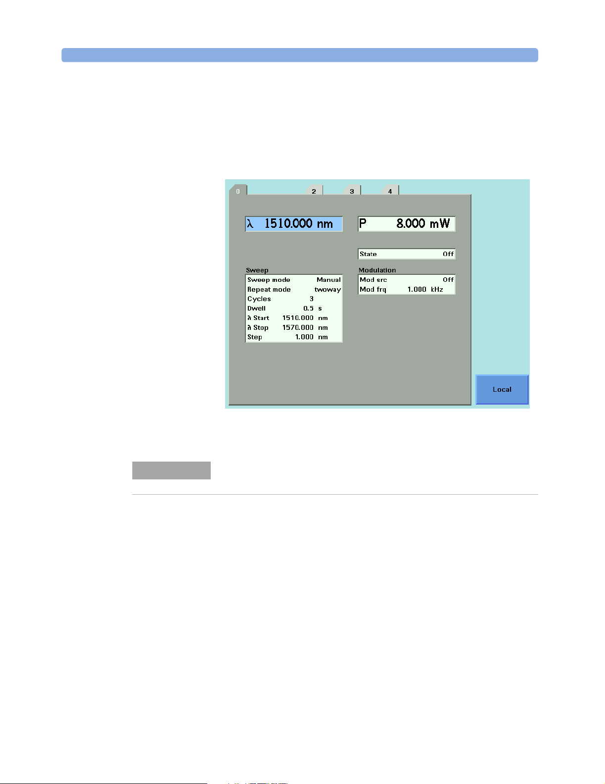
Returning the Instrument to Local Control
If the instrument is in remote control, a screen resembling
Figure 1 will appear. Press [Local] if you wish to return the instrument to
local control.
NOTE
Figure 1 Remote Control
If your Agilent 8163A/B, 8164A/B or 8166A/B is in local lockout mode
(refer to DISPlay:LOCKout on page 142) the Local softkey is not available.
18 Agilent 8163A/B, 8164A/B & 8166A/B Mainframes, Fifth Edition
Page 19

Message Queues Introduction to Programming
Message Queues
The instrument exchanges messages using an input and an output queue.
Error messages are kept in a separate error queue.
Agilent 8163A/B, 8164A/B & 8166A/B Mainframes, Fifth Edition 19
Page 20

Introduction to Programming Message Queues
How the Input Queue Works
The input queue is a FIFO queue (first-in first-out). Incoming bytes are
stored in the input queue as follows:
1 Receiving a byte:
• Clears the output queue.
• Clears Bit 7 (MSB).
2 No modification is made inside strings or binary blocks. Outside strings
and binary blocks, the following modifications are made:
• Lower-case characters are converted to upper-case.
• The characters 00
(2016).
• Two or more blanks are truncated to one.
3 An EOI (End Or Identify) sent with any character is put into the input
queue as the character followed by a line feed (LF, 0A
with a LF, only one LF is put into the input queue.
4 The parser starts if the LF character is received or if the input queue is
full.
to 0916 and 0B16 to 1F16 are converted to spaces
16
). If EOI is sent
16
Clearing the Input Queue
Switching the power off, or sending a Device Interface Clear signal, causes
commands that are in the input queue, but have not been executed to be
lost.
20 Agilent 8163A/B, 8164A/B & 8166A/B Mainframes, Fifth Edition
Page 21

Message Queues Introduction to Programming
The Output Queue
The output queue contains responses to query messages. The instrument
transmits any data from the output queue when a controller addresses the
instrument as a talker.
Each response message ends with a carriage return (CR, 0D
), with EOI=TRUE. If no query is received, or if the query has an error,
(0A
16
the output queue remains empty.
The Message Available bit (MAV, bit 4) is set in the Status Byte register
whenever there is data in the output queue.
) and a LF
16
Agilent 8163A/B, 8164A/B & 8166A/B Mainframes, Fifth Edition 21
Page 22

Introduction to Programming Message Queues
The Error Queue
The error queue is 30 errors long. It is a FIFO queue (first-in first-out). That
is, the first error read is the oldest error to have occurred. For example:
1 If no error has occurred, the error queue contains:
+ 0, "No error"
2
After a command such as wav:pow, the error queue now contains:
+ 0, "No error"
-113, "Undefined header"
3
If the command is immediately repeated, the error queue now contains:
+ 0, "No error"
-113, "Undefined header"
-113, "Undefined header"
If more than 29 errors are put into the queue, the message:
-350, "Queue overflow"
is placed as the last message in the queue.
22 Agilent 8163A/B, 8164A/B & 8166A/B Mainframes, Fifth Edition
Page 23

Programming and Syntax Diagram Conventions Introduction to Programming
Programming and Syntax Diagram Conventions
A program message is a message containing commands or queries that
you send to the instruments. The following are a few points about program
messages:
• You can use either upper-case or lower-case characters.
• You can send several commands in a single message. Each command
must be separated from the next one by a semicolon (
• A command message is ended by a line feed character (LF) or
<CR><LF>.
• You can use any valid number/unit combination.
;).
In other words,
If you do not specify a unit, then the default unit is assumed. The default
unit for the commands are given with command description in the next
chapter.
1500NM,1.5UM and 1.5E-6M are all equivalent.
Agilent 8163A/B, 8164A/B & 8166A/B Mainframes, Fifth Edition 23
Page 24

Introduction to Programming Programming and Syntax Diagram Conventions
Short Form and Long Form
The instrument accepts messages in short or long forms.
For example, the message
:STATUS:OPERATION:ENABLE 768
is in long form.
The short form of this message is
STAT:OPER:ENAB 768
:
In this manual, the messages are written in a combination of upper and
lower case. Upper case characters are used for the short form of the
message.
For example, the above command would be written
STATus:OPERation:ENABle
:
The first colon can be left out for the first command or query in your
message. That is, the example given above could also be sent as
STAT:OPER:ENAB 768
24 Agilent 8163A/B, 8164A/B & 8166A/B Mainframes, Fifth Edition
Page 25

Programming and Syntax Diagram Conventions Introduction to Programming
Command and Query Syntax
All characters not between angled brackets must be sent exactly as
shown.
The characters between angled brackets (
<...>) indicate the kind of data
that you should send, or that you get in a response. You do not type the
angled brackets in the actual message.
Descriptions of these items follow the syntax description. The following
types of data are most commonly used:
string is ascii data. A string is contained between double quotes ("...") or
single quotes (‘...’).
value is numeric data in integer (12), decimal (34.5) or exponential format
(67.8E-9).
wsp is a white space.
Other kinds of data are described as required.
The characters between square brackets (
[...]) show optional information
that you can include with the message.
The bar (
|) shows an either-or choice of data, for example, a|b means
either a or b, but not both simultaneously.
Extra spaces are ignored, so spaces can be inserted to improve readability.
Units
Where units are given with a command, usually only the base units are
specified. The full sets of units are given in the table below.
Table 2 Units and allowed Mnemonics
Unit Default Allowed Mnemonics
meters M PM, NM, UM, MM, M
decibel DB MDB, DB
second S NS, US, MS, S
decibel/1mW DBM MDBM, DBM
Hertz HZ HZ, KHZ, MHZ, GHZ, THZ
Watt Watt PW, NW, UW, MW, Watt
meters per second M/S NM/S, UM/S, MM/S, M/S
Agilent 8163A/B, 8164A/B & 8166A/B Mainframes, Fifth Edition 25
Page 26

Introduction to Programming Programming and Syntax Diagram Conventions
Data Types
With the commands you give parameters to the instrument and receive
response values from the instrument. Unless explicitly specified these
data are given in ASCII format. The following types of data are used:
• Boolean data may only have the values 0 or 1.
• Integer range is given for each individual command.
• Float variables may be given in decimal or exponential writing (0.123 or
123E-3).
All Float values conform to the 32 bit IEEE Standard, that is, all Float
values are returned as 32-bit real values.
•A string is contained between double quotes (
(‘...’). When the instrument returns a string, it is always included in " "
and terminated by
•When a register value is given or returned (for example *ESE), the
decimal values for the single bits are added. For example, a value of
nine means that bit 0 and bit 3 are set.
• Larger blocks of data are given as Binary Blocks, preceded by
“#<H><Len><Block>”, terminated by <END>; <H> represents the
number of digits, <Len> represents the number of bytes, and <Block> is
the data block. For example, for a Binary Block with 1 digit and 6 bytes
this is: #16TRACES<END>.
<END>.
"...") or single quotes
Slot and Channel Numbers
Each module is identified by a slot number and a channel number. For
commands that require you to specify a channel, the slot number is
represented by [n] in a command and the channel number is represented
by [m].
The slot number represents the module’s position in the mainframe. These
are:
• from one to two for the Agilent 8163A/B,
• from zero to four for the Agilent 8164A/B, and
• from one to seventeen for the Agilent 8166A/B.
These numbers are displayed on the front panel beside each module slot.
26 Agilent 8163A/B, 8164A/B & 8166A/B Mainframes, Fifth Edition
Page 27

Programming and Syntax Diagram Conventions Introduction to Programming
NOTE
NOTE
NOTE
The Agilent 8164A/B slot for a back-loadable tunable laser module is
numbered zero.
Channel numbers apply to modules that have two inputs/outputs, for
example, the Agilent 81635A Dual Power Sensor.
Modules with two channels, for example, the Agilent 81635A Dual Power
Sensor, use the channel number to distinguish between these channels.
The channel number of single channel modules is always one.
For example, if you want to query slot 1, channel 2 with the command,
“:SENSe[n]:[CHANnel[m]]:POWer:WAVelength?” on page 109, you should
send the command:
•:sens1:chan2:pow:wav?
If you do not specify a slot or channel number, the lowest possible number
is used as the default value. This means:
• Slot 1 for the Agilent 8163A/B and Agilent 8166A/B mainframes.
• Slot 0 for the Agilent 8164A/B mainframe.
• Channel 1 for all channels.
Laser Selection Numbers
The laser selection number, [l], identifies the upper or lower wavelength
laser source for dual wavelength Laser Source modules and Return Loss
modules with two internal laser sources. The lower wavelength source is
denoted by 1. The upper wavelength source is denoted by 2.
Agilent 8163A/B, 8164A/B & 8166A/B Mainframes, Fifth Edition 27
Page 28

Introduction to Programming Programming and Syntax Diagram Conventions
NOTE
For Return Loss modules, 0 denotes the use of an external laser source as
the input to your Return Loss module for the following commands:
• “:SENSe[n]:[CHANnel[m]]:RETurnloss:CORRection:FPDelta[l]” on
page 111,
• “:SENSe[n]:[CHANnel[m]]:RETurnloss:CORRection:FPDelta[l]?” on
page 111,
• “:SENSe[n]:[CHANnel[m]]:RETurnloss:CORRection:REFLectance[l]” on
page 112, and
• “:SENSe[n]:[CHANnel[m]]:RETurnloss:CORRection:FPDelta[l]” on
page 111.
28 Agilent 8163A/B, 8164A/B & 8166A/B Mainframes, Fifth Edition
Page 29

Common Commands Introduction to Programming
Common Commands
The IEEE 488.2 standard has a list of reserved commands, called common
commands. Some of these commands must be implemented by any
instrument using the standard, others are optional.
Your instrument implements all the necessary commands, and some
optional ones. This section describes the implemented commands.
Agilent 8163A/B, 8164A/B & 8166A/B Mainframes, Fifth Edition 29
Page 30

Introduction to Programming Common Commands
Common Command Summary
Table 3 gives a summary of the common commands.
Table 3 Common Command Summary
Command Parameter Function Page
*CLS Clear Status Command page 57
*ESE Standard Event Status Enable Command page 57
*ESE? Standard Event Status Enable Query page 58
*ESR? Standard Event Status Register Query page 58
*IDN? Identification Query page 59
*OPC Operation Complete Command page 59
*OPC? Operation Complete Query page 60
*OPT? Options Query page 60
NOTE
*RST Reset Command page 61
*STB? Read Status Byte Query page 61
*TST? Self Test Query page 62
*WAI Wait Command page 63
These commands are described in more detail in “IEEE-Common
Commands” on page 56.
30 Agilent 8163A/B, 8164A/B & 8166A/B Mainframes, Fifth Edition
Page 31

Common Commands Introduction to Programming
Common Status Information
There are three registers for the status information. Two of these are
status-registers and one is an enable-registers. These registers conform to
the IEEE Standard 488.2-1987. You can find further descriptions of these
registers under
Figure 2 shows how the Standard Event Status Enable Mask (SESEM)
and the Standard Event Status Register (SESR) determine the Event Status
Bit (ESB) of the Status Byte.
*ESE, *ESR?, and *STB?.
*ESE sets the Standard Event Status Enable Mask
Event
Status
*STB? returns the Status Byte Register
OSB ESB QSB
Status
Byte
001
All bits shown as are unused
Figure 2 The Event Status Bit
MAV
0
Enable
Mask
OR
&
&
&
&
&
&
01234567
Event
Status
Register
*ESR? returns the Standard Event Status Register
The SESR contains the information about events that are not slot specific.
For details of the function of each bit of the SESR, see “Standard Event
Status Register” on page 37.
01234567
111111
&
&
01234567
100000
The SESEM allows you to choose the event that may affect the ESB of the
Status Byte. If you set a bit of the SESEM to zero, the corresponding event
cannot affect the ESB. The default is for all the bits of the SESEM to be set
to 0.
The questionable and operation status systems set the Operational Status
Bit (OSB) and the Questionable Status Bit (QSB). These status systems
are described in “The Status Model” on page 33 and “Status Reporting –
The STATus Subsystem” on page 64.
Agilent 8163A/B, 8164A/B & 8166A/B Mainframes, Fifth Edition 31
Page 32

Introduction to Programming Common Commands
NOTE
Unused bits in any of the registers change to 0 when you read them.
32 Agilent 8163A/B, 8164A/B & 8166A/B Mainframes, Fifth Edition
Page 33

The Status Model Introduction to Programming
The Status Model
Status Registers
Each node of the status circuitry has three registers:
• A condition register (CONDition), which contains the current status.
This register is updated continuously. It is not changed by having its
contents read.
• The event register (EVENt), which contains details of any positive
transitions in the corresponding condition register, that is, when a bit
changes from 0 → 1. The contents of this register are cleared when it is
read. The contents of any higher-level registers are affected with regard
to the appropriate bit.
• The enable register (ENABle), which enables changes in the event
register to affect the next stage of registers.
NOTE
The event register is the only kind of register that can affect the next stage
of registers.
The structures of the Operational and Questionable Status Systems are
similar. Figure 4 describe how the Questionable Status Bit (QSB) and the
Operational Status Bit (OSB) of the Status Byte Register are determined.
Enable Registers
To th e
Condition Register
of the Next Node
→
1.
→
1,
11111
OR
Event Registers
A positive transition in the condition
register, when a bit changes from 0
causes the corresponding bit of the
corresponding event register
to change from 0
Condition Registers
Figure 3 The Registers and Filters for a Node
Agilent 8163A/B, 8164A/B & 8166A/B Mainframes, Fifth Edition 33
Page 34

Introduction to Programming The Status Model
The Operational/Questionable Slot Status Event Register (OSSER/QSSER)
contains the status of a particular module slot. A bit changes from 0 → 1
when an event occurs, for example, when a laser is switched on. For
details of the function of each bit of these registers, see
“Operation/Questionable Status Summary Register” on page 38.
The Operational/Questionable Slot Enable Status Mask (OSESM/QSESM)
allows you to choose the events for each module slot that may affect the
Operational/Questionable Status Event Register (see below). If you set a
bit of the OSESM/QSESM to zero, the occurence of the corresponding
event for this particular module slot cannot affect the
Operational/Questionable Status Event Register. The default is for all the
bits of the OSESM/QSESM to be set to 0.
The Operational/Questionable Status Event Summary Register
(OSESR/QSESR) summarizes the status of every module slot of your
instrument. If, for any slot, any bit of the QSSER goes from 0 → 1 AND the
corresponding bit of the QSSEM is 1 at the same time, the QSESR bit
representing that slot is set to 1.
The Operational/Questionable Status Enable Summary Mask
(OSESM/QSESM) allows you to choose the module slots that may affect
the OSB/QSB of the Status Byte. If any bit of the QSESR goes from 0 → 1
AND the corresponding bit of the QSESM is 1 at the same time, the QSB of
the Status Byte is set to 1. If you set a bit of the OSESM/QSESM to zero,
the corresponding module slot cannot affect the OSB/QSB. The default is
for all the bits of the OSESM/QSESM to be set to 0.
The Operational/Questionable Status Enable Summary Mask for the
Agilent 8163A/B Lightwave Multimeter and the Agilent 8164A/B
Lightwave Measurement System consists of one level. These are
described in “Status System for 8163A/B & 8164A/B” on page 35.
As the Agilent 8166A/B Lightwave Multichannel System has 17 module
slots, the Operational/Questionable Status Enable Summary Mask
consists of two levels. This is described in “Status System for 8166A/B”
on page 36.
34 Agilent 8163A/B, 8164A/B & 8166A/B Mainframes, Fifth Edition
Page 35

The Status Model Introduction to Programming
Status System for 8163A/B & 8164A/B
The status system for the Agilent 8163A/B Lightwave Multimeter and the
Agilent 8164A/B Lightwave Measurement System returns the status of 2
and 5 module slots respectively. The Operational/Questionable Status
Summary Registers consist of one level and are described by Figure 4 .
Any commands that require LEVel1 do not apply to these mainframes.
Status Byte Register
Status Summary
Slot 1
Operational/Questionable Status
Enable Summary Mask
Register
Operational/Questionable Status
Event Summary Register
Operational/Questionable Status
Condition Summary Register
Operational/Questionable
Slot Status Enable Mask
Register
Operational/Questionable
Slot Status Event
Register
Operational/Questionable
Slot Status Condition
Register
Status Byte
to next
&
&
&
&
&
&
OR
for a positive
transition
&
&
to next
level
OR
for a positive
transition
level
Figure 4 The Operational/Questionable Status System for 8163A/B & 8164A/B
Agilent 8163A/B, 8164A/B & 8166A/B Mainframes, Fifth Edition 35
Page 36

Introduction to Programming The Status Model
Status System for 8166A/B
The status system for the Agilent 8166A/B Lightwave Multichannel
System returns the status of 17 module slots. The
Operational/Questionable Status Summary Registers consists of two
levels, as described by Figure 5 .
Module slots 1 to 14 affect the Level 0 summary register as described in
Figure 4 . Bit 0 of the Level 0 summary registers represents the summary
of the status of module slots 15, 16, and 17. The Level 1 summary registers
contain an individual summary for each of these module slots.
Status Byte Register
Status
Summary
for Level 0
Status
Summary
for Level 1
Slot 15
Operational/Questionable Status
Enable Summary Mask
Register (Level 1)
Operational/Questionable Status
Event Summary Register (Level 1)
Operational/Questionable Status
Condition Summary Register (Level 1)
Operational/Questionable
Slot Status Enable Mask
Register
Operational/Questionable
Slot Status Event
Register
Operational/Questionable
Slot Status Condition
Register
Operational/Questionable Status
Enable Summary Mask
Register (Level 0)
Operational/Questionable Status
Event Summary Register (Level 0)
Operational/Questionable Status
Condition Summary Register (Level 0)
&
&
&
&
&
&
&
OR
for a positive
transition
Status Byte
&
&
OR
&
for a positive
transition
to next
level
&
&
to next
to next
level
OR
for a positive
transition
level
Figure 5 The Operational/Questionable Status System for 8166A/B
36 Agilent 8163A/B, 8164A/B & 8166A/B Mainframes, Fifth Edition
Page 37

The Status Model Introduction to Programming
Annotations
Status Byte Register
• Bit 3, the QSB, is built from the questionable event status register and
its enable mask.
• Bit 4, the MAV, is set if the message output queue is not empty.
• Bit 5, the ESB, is built from the SESR and its SESEM.
• Bit 7, the OSB, is built from the operation event status register and its
enable mask.
• All other bits are unused, and therefore set to 0.
Standard Event Status Register
• Bit 0 is set if an operation complete event has been received since the
last call to *ESR?.
• Bit 1 is always 0 (no service request).
• Bit 2 is set if a query error has been detected.
• Bit 3 is set if a device dependent error has been detected.
• Bit 4 is set if an execution error has been detected.
• Bit 5 is set if a command error has been detected.
• Bit 6 is always 0 (no service request).
• Bit 7 is set for the first call of *ESR? after Power On.
Operation/Questionable Status Summary
• The Operation/Questionable Status Summary consist of a condition and
an event register.
• A "rising" bit in the condition register is copied to the event register.
• A "falling" bit in the condition register has no effect on the event
register.
• Reading the condition register is non-destructive.
• Reading the event register is destructive.
• A summary of the event register and its enable mask is set in the status
byte.
Agilent 8163A/B, 8164A/B & 8166A/B Mainframes, Fifth Edition 37
Page 38

Introduction to Programming The Status Model
Operation/Questionable Status Summary Register
• Bits 0 to 4 are built from the OSSER/QSSER and the OSSEM/QSSEM.
• A summary of the event register, the condition register and the enable
mask is set in the status byte.
Operation/Questionable Slot Status
• The Operation/Questionable Slot Status consist of a condition and an
event register.
• A "rising" bit in the condition register is copied to the event register.
• A "falling" bit in the condition register has no effect on the event
register.
• Reading the condition register is non-destructive.
• Reading the event register is destructive.
• A summary of the event register, the condition register and the enable
mask is set in the status byte.
Operation Slot Status Register
• Bit 0 is set if the laser is switched on.
• Bit 1 is set if the Coherence Control is switched on.
• Bit 3 is set if Power Meter zeroing or Tunable Laser module lambda
zeroing is ongoing.
• Bit 4 is set if the attenuator output is enabled (shutter open).
• Bits 5 - 7 are set if the wavelength offset table is enabled (see page 68).
• All other bits are unused, and therefore set to 0.
Questionable Slot Status Register
• Bit 0 is set if excessive power is set by the user for any source module
or if excessive averaging time is set for any Power Meter.
• Bit 1 is set if the last Power Meter zeroing failed.
• Bit 2 is set if temperature is out of range.
• Bit 3 is set if laser protection is switched on.
38 Agilent 8163A/B, 8164A/B & 8166A/B Mainframes, Fifth Edition
Page 39

The Status Model Introduction to Programming
• Bit 4 is set if the module has not settled, as during the automatic
settling of a Tunable Laser module.
• Bit 5 is set if the module is out of specifications, or if lambda zeroing
failed for a Tunable Laser module.
• Bit 6 is set if ARA is recommended.
• Bit 7 is set if the duty cycle is out of range.
• Bit 8 is set if coherence control is uncalibrated
• Bit 9 is set if attenuator beam path protection is enabled (shutter is
closed)
• Bit 10 is set if lambda zeroing is recommended.
• All other bits are unused, and therefore set to 0.
Agilent 8163A/B, 8164A/B & 8166A/B Mainframes, Fifth Edition 39
Page 40

Introduction to Programming The Status Model
Status Command Summary
*STB? returns status byte, value 0 .. +255
*ESE sets the standard event status enable mask, parameter 0 .. +255
*ESE? returns SESE, value 0 .. +255
*ESR? returns the standard event status register, value 0 .. +255
*OPC parses all program message units in the message queue, and prevents
the instrument from executing any further commands until all pending
commands are completed.
*OPC? returns 1 if all operations (scan trace printout, measurement) are com
pleted. Otherwise it returns 0.
*CLS clears the status byte and SESR, and removes any entries from the er
ror queue.
*RST clears the error queue, loads the default setting, and restarts communi
cation.
NOTE: *RST does NOT touch the STB or SESR. A running measurement
is stopped.
*TST? initiates an instrument selftest and returns the results as a 32 bit
LONG.
40 Agilent 8163A/B, 8164A/B & 8166A/B Mainframes, Fifth Edition
Page 41

The Status Model Introduction to Programming
Other Commands
*OPT? returns the installed modules and the slots these modules are installed
in:
For example, *OPT? → 81682A, 81533B, 81532A, ,
Modules 81682A, 81533B, and 81532A are installed in slots 0 to 2 re
spectively. Slots 3 and 4 are empty.
*WAI prevents the instrument from executing any further commands until the
current command has finished executing. All pending operations are
completed during the wait period.
*IDN? identifies the instrument; returns the manufacturer, instrument model
number, serial number, and firmware revision level.
Agilent 8163A/B, 8164A/B & 8166A/B Mainframes, Fifth Edition 41
Page 42

Introduction to Programming The Status Model
42 Agilent 8163A/B, 8164A/B & 8166A/B Mainframes, Fifth Edition
Page 43

2
Specific Commands
This chapter lists all the instrument specific commands relating to the
Agilent 8163A/B Lightwave Multimeter, the Agilent 8164A/B Lightwave
Measurement System, and the Agilent 8166A/B Lightwave Multichannel
System with a single-line description.
Each of these summaries contains a page reference for more detailed
information about the particular command later in this manual.
Specific Command Summary . . . . . . . . . . . . . . . . . . . . . . . 44
Agilent 8163A/B, 8164A/B & 8166A/B Mainframes, Fifth Edition 43
Page 44

Specific Commands Specific Command Summary
Specific Command Summary
The commands are ordered in a command tree. Every command belongs to
a node in this tree.
The root nodes are also called the subsystems. A subsystem contains all
commands belonging to a specific topic. In a subsystem there may be
further subnodes.
All the nodes have to be given with a command. For example in the
command
• DISPlay is the subsystem containing all commands for controlling the
display,
BRIGhtness is the command selecting brightness.
•
disp:brig
NOTE
disp:brig/? means that disp:brig and disp:brig? are both available.
So,
Table 4 gives an overview of the command tree. You see the nodes, the
subnodes, and the included commands.
Table 4 Specific Command Summary
Command Description Page
:CONFigure[n][:CHANnel[m]]:OFFSet
:WAVelength:REFerence/? Sets or queries the slot and channel of the external reference
powermeter.
:WAVelength:STATe/? Switches or queries attenuator Offset Table on or off/? page 160
:WAVelength:TABle? Queries the complete offset table. page 164
:WAVelength:TABle:SIZE? Queries the size of the offset table. page 164
:WAVelength:VALue Adds a value pair (wavelength, offset) to the offset table. page 161
:WAVelength:VALue:DELete Deletes an offset value pair. page 163
:WAVelength:VALue:DELete:ALL Deletes all value pairs from the offset table. page 163
If a command and a query are both available, the command ends /?.
page 161
:WAVelength:VALue:OFFSet? Queries an offset value according to wavelength or index. page 162
:WAVelength:VALue:PAIR? Queries an offset/wavelength value pair according to wavelength
or index.
:WAVelength:VALue:WAVelength? Queries a wavelength value from its index in the offset table page 162
page 163
44 Agilent 8163A/B, 8164A/B & 8166A/B Mainframes, Fifth Edition
Page 45

Specific Command Summary Specific Commands
Table 4 Specific Command Summary (continued)
Command Description Page
:DISPlay
:BRIGhtness/? Controls or queries the current display brightness. page 186
:CONTrast/? Controls or queries the current display contrast. page 186
:ENABle/? Switches the display on or off, or queries whether the display is
page 187
on or off.
:LOCKout/? Sets or queries local lockout mode. page 187
:FETCh[n][:CHANnel[m]][:SCALar]
:POWer[:DC]? Returns a power value from a sensor. page 87
:RETurnloss? Returns the current return loss value. page 87
:MONitor? Returns the current power value from the monitor diode within a
page 88
return loss module.
:INITiate[n]:[CHANnel[m]]
[:IMMediate] Starts a measurement. page 88
:CONTinuous/? Starts or Queries a single/continuous measurement. page 89
:LOCK/?
Switches the lock on/off or returns the current state of the lock. page 80
:INPUT[n][:CHANnel[m]]
:ATTenuation/? Sets or returns the attenuation factor for the instrument. page 148
:OFFset/? Sets or returns the offset factor for the instrument. page 149
:OFFset:DISPlay Sets the offset factor so that attenuation factor is zero. page 149
:OFFset:POWermeter Sets the offset factor to the difference between the power mea-
page 150
sured with a powermeter and with the monitor diode.
:ATTenuation:SPEed/? Sets or queries the filter transition speed page 150
:WAVelength/? Sets or queries the modules attenuation wavelength page 151
:OUTPut[n][:CHANnel[m]]
:APMode/? Sets or queries whether power setting or attenuation value has
page 151
been changed.
:APOWeron/? Sets or queries the shutter status at power on. page 157
:ATIMe/? Sets or queries the powermeter averaging time. page 157
:CONNection/? Selects or returns Analog Output parameter. page 113
:CORRection:COLLection:ZERO Zeros the offsets of attenuators powermeter page 157
:CORRection:COLLection:ZERO:ALL Zeros all available powermeter channels in mainframe page 158
Agilent 8163A/B, 8164A/B & 8166A/B Mainframes, Fifth Edition 45
Page 46

Specific Commands Specific Command Summary
Table 4 Specific Command Summary (continued)
Command Description Page
:CORRection:COLLection:ZERO? Queries the status of the last zero operation page 158
:PATH/? Sets or returns the regulated path. page 113
:POWer/? Sets or queries the output power value. page 152
:POWer:CONTRol/? Sets or queries power control mode status page 155
:POWer:OFFSet/? Sets or queries the power offset value. page 154
:POWer:OFFSet:POWermeter Calculates power offset from measured power values page 154
:POWer:REFerence/? Sets or queries the reference power value. page 153
:POWer:REFerence:POWermeter Copies power value from power meter to attenuator module ref.
power parameter
:POWer:UNit/? Sets or queries power unit used (dBm or W) page 155
[:STATe]/? Sets a source’s or attenuators output terminals to open or closed
or returns the current status of a source’s or attenuators output
terminals.
:READ[n][:CHANnel[m]]
[:SCALar]:POWer[:DC]? Reads the current power value from a sensor. page 89
:POWer[:DC]:ALL? Reads all available power meter channels. page 90
:POWer[:DC]:ALL:CONFig? Return all the slot and channel number of every available power
meter channel.
[:SCALar]:RETurnloss? Reads the current return loss value. page 91
[:SCALar]:MONitor? Returns the current power value from the monitor diode within a
return loss module.
:ROUTe[n]
[:CHANnel[m]]/? Sets or returns the channel route between two ports. page 169
[:CHANnel[m]]:CONFig? Reads the switch configuration of an instrument. page 170
[:CHANnel[m]]:CONFig:ROUTe? Reads the allowed switch routes of an instrument. page 170
page 153
page 114
page 90
page 91
46 Agilent 8163A/B, 8164A/B & 8166A/B Mainframes, Fifth Edition
Page 47

Specific Command Summary Specific Commands
Table 4 Specific Command Summary (continued)
Command Description Page
:SENSe[n][:CHANnel[m]]:CORRection
[:LOSS][:INPut][:MAGNitude]/? Sets or returns the value of correction data for a sensor. page 92
:COLLECT:ZERO Executes a zero calibration of a sensor module. page 92
:COLLECT:ZERO? Returns the current zero state of a sensor module. page 93
:COLLECT:ZERO:ALL Executes a zero calibration of all sensor modules. page 93
:SENSe[n][:CHANnel[m]]:FUNCtion
:PARameter:LOGGing/? Sets or returns the number of samples and the averaging time,
, for logging.
t
avg
page 94
:PARameter:MINMax/? Sets or returns the minmax mode and the window size. page 95
:PARameter:STABility/? Sets or returns the total time, delay time and the averaging time,
, for stability.
t
avg
page 96
:RESult? Returns the data array of the last function. page 97
:RESult:BLOCk? Returns a specified binary block from the data array for the last
page 98
power meter data acquisition function.
:RESult:MAXBlocksize? Returns the maximum block size for power meter data acquisition
page 98
functions.
:RESult:MONitor? For return loss module, returns monitor diode data array of last
page 99
function.
:STATe/? Enables/disables the function mode or returns whether the func-
page 100
tion mode is enabled.
:THReshold/? Sets or returns the threshold value and the start mode. page 101
:SENSe[n][:CHANnel[m]]:POWer
:ATIMe/? Sets or returns the average time of a sensor. page 101
:RANGe[:UPPer]/? Sets or returns the most positive signal entry expected for a sen-
page 102
sor.
:RANGe:MONitor[:UPPer]/? Sets or returns the range of the monitor diode within a return loss
page 103
module.
:RANGe:AUTO/? Sets or returns the range of a sensor to produce the most dynam-
page 104
ic range without overloading.
:REFerence/? Sets or returns the reference level of a sensor. page 105
:UNIT/? Sets or returns the units used for absolute readings on a sensor. page 108
:WAVelength/? Sets or returns the wavelength for a sensor. page 108
Agilent 8163A/B, 8164A/B & 8166A/B Mainframes, Fifth Edition 47
Page 48

Specific Commands Specific Command Summary
Table 4 Specific Command Summary (continued)
Command Description Page
:SENSe[n][:CHANnel[m]]:POWer:Reference
:DISPlay Sets the reference level for a sensor from the input power level. page 106
:STATe/? Sets or returns whether sensor results are in relative or absolute
units.
:STATe:RATio/? Sets or returns whether sensor results are displayed relative to a
channel or to an absolute reference.
:SENSe[n][:CHANnel[m]]:RETurnloss:CALibration
:FACTory Sets the calibration value to factory settings. page 109
:COLLect:REFLectance Sets the reference reflectance calibration values to the values
currently measured by the chosen return loss module. (When, for
example, a gold reflector is used.)
:COLLect:TERMination Sets the termination calibration values to the values currently
measured by the chosen return loss module.
:COLLect:VALues? Returns current calibration values. page 110
:TERMination? Returns T-Value page 110
:SENSe[n][:CHANnel[m]]:RETurnloss:CORRection
:FPDelta[l]/? Sets or returns front panel delta, that is, the loss correction value
due, for example, to the front panel connector.
:REFLectance[l]/? Sets or returns the return loss reference, the return loss value of
your reference reflector.
:SLOT[n]
page 106
page 106
page 109
page 110
page 111
page 112
:EMPTy? Returns whether the module slot is empty. page 81
:IDN? Returns information about the module. page 81
:OPTions? Returns the module’s options. page 81
:TST? Returns the latest selftest results for a module. page 82
:SLOT[n][:HEAD[m]]
:EMPTy? Returns whether an optical head is connected. page 82
:IDN? Returns information about the optical head. page 82
:OPTions? Returns the optical head’s options. page 83
:TST? Returns the latest selftest results for an optical head. page 83
:WAVelength:RESPonse? Returns the wavelength response from the module with wave-
length calibration.
:WAVelength:RESPonse:CSV? Returns the wavelength response from the module with wave-
length calibration.
page 83
page 84
48 Agilent 8163A/B, 8164A/B & 8166A/B Mainframes, Fifth Edition
Page 49

Specific Command Summary Specific Commands
Table 4 Specific Command Summary (continued)
Command Description Page
:WAVelength:RESPonse:SIZE? Returns the no. of elements in the wavelength response table. page 84
[:SOURce[n]][:CHANnel[m]]
:MODout/? Returns the mode of the modulation output mode of the BNC
page 121
connector on the front panel of Agilent 81640A/80A/82A Tunable Laser modules.
[:SOURce[n]][:CHANnel[m]]:AM
[:INTernal]:FREQuency[l]/? Sets or returns the frequency of an internal signal source. page 115
:SOURce[l]/? Sets or returns a source for the modulating system. page 116
:STATe[l]/? Turns Amplitude Modulation of a source on or off or queries
page 117
whether Amplitude Modulation is on or off.
:COHCtrl:COHLevel[l]/? Sets or returns the coherence level. page 118
[:SOURce[n]][:CHANnel[m]]:FM
:SOURce[l]/? Sets or returns the type of frequency modulaion employed, spe-
page 118
cifically Simulated Brillouin Scattering (SBS) control.
:STATe[l]/? Turns Frequency Modulation of a source on or off or queries
page 119
whether Frequency Modulation is on or off.
:SBSCtrl:FREQuency[l]/? Sets or returns the frequency of SBS Control modulation. page 120
:SBSCtrl:LEVel[l]/? Sets or returns the level of SBS Control modulation
page 120
(as a percentage of maximum)
[:SOURce[n]][:CHANnel[m]:]POWer
:LEVel][:IMMediate][:AMPLitude[l]] Sets the laser output power of a source. page 124
[
:LEVel][:IMMediate][:AMPLitude[l]]? Returns the laser output power of a source. page 125
[
[:LEVel]:RISetime[l]/? Sets or returns the laser rise time of a source. page 126
:ATTenuation[l]/? Sets or returns the attenuation level for a source. page 122
:STATe/? Sets or returns the state of the source output signal. page 127
:UNIT/? Sets or returns the power units. page 127
:WAVelength/? Sets or returns the wavelength source of a dual-wavelength
page 128
source.
[:SOURce[n]][:CHANnel[m]:]POWer:ATTenuation[l]
:AUTO/? Selects Automatic or Manual Attenuation Mode for a source or
page 123
returns the selected mode.
:DARK/? Enables/disables ‘dark’ position on a source or returns whether
page 123
‘dark’ position is active for a source.
Agilent 8163A/B, 8164A/B & 8166A/B Mainframes, Fifth Edition 49
Page 50

Specific Commands Specific Command Summary
Table 4 Specific Command Summary (continued)
Command Description Page
[:SOURce[n]][:CHANnel[m]:]READout
:DATA? Returns number of datapoints returned by the
[:SOURce[n]][:CHANnel[m]]:READout:POINts? command.
:DATA:BLOCk? Returns a specified binary block from either a lambda logging op-
eration, or maximum power at wavelength characteristic.
:DATA:MAXBlocksize? Returns the maximum blocksize that a lambda logging, or maxi-
mum power at wavelength characteristic will return.
:POINts? Returns the data as a binary stream from either a lambda logging
operation or the maximum power the laser can produce at each
wavelength.
[:SOURce[n]][:CHANnel[m]:]WAVelength
[:CW[l]:FIXED] Sets the absolute wavelength of a source. page 130
[:CW[l]:FIXED[l]]? Returns the absolute wavelength of a source. page 131
:FREQuency[l]/? Sets the frequency difference used to calculate a relative wave-
length for a source.
:REFerence[l]? Returns the reference wavelength of a source. page 135
[:SOURce[n]][:CHANnel[m]:]WAVelength:CORRection
:ARA Realigns the laser cavity. page 131
:ARA:ALL Realigns the laser cavity of every tunable laser source in the
mainframe.
:AUTocalib Sets or returns tunable laser source Auto Calibration state. page 132
page 129
page 129
page 129
page 130
page 134
page 132
:ZERO Executes a wavelength zero. page 132
:ZERO:ALL Executes a wavelength zero on every tunable laser source in the
mainframe.
:ZERO:TEMPerature:ACTual? Reports the current lambda zero temperature page 133
:ZERO:TEMPerature:DIFFerence? Reports the temperature difference required to trigger an auto
lamda zero.
:ZERO:TEMPerature:LASTzero? Reports the temperature at which the last auto lamda zero took
place.
:ZERO:AUTO Forces an auto lamda zero. This is quicker than the equilavent
manual process.
[:SOURce[n]][:CHANnel[m]:]WAVelength:REFerence
:DISPlay Sets the reference wavelength of a source to the value of the out-
put wavelength.
page 133
page 134
page 134
page 134
page 135
50 Agilent 8163A/B, 8164A/B & 8166A/B Mainframes, Fifth Edition
Page 51

Specific Command Summary Specific Commands
Table 4 Specific Command Summary (continued)
Command Description Page
[:SOURce[n]][:CHANnel[m]:]WAVelength:SWEep
:CHECkparams? Returns whether sweep parameters set are consistent. page 136
:CYCLes/? Sets or returns the number of cycles. page 137
:DWELl/? Sets or returns the dwell time. page 138
:EXPectedtriggers? Returns number of triggers (used to configure power meter). page 138
:FLAG? Returns whether waiting for trigger, or logging data available. page 139
:LLOGging/? Switches lambda logging on or off or queries the state of lambda
page 140
logging.
:MODE/? Sets or returns the sweep mode. page 141
:PMAX? Returns the highest permissible power for a wavelength sweep. page 141
:REPeat/? Sets or returns the repeat mode. page 142
:SOFTtrigger Sends a soft trigger. page 143
:SPEed/? Sets or returns the speed for continuous sweeping. page 143
:STARt/? Sets or returns the start point of the sweep. page 144
:STOP/? Sets or returns the end point of the sweep. page 144
[:STATe]/? Stops, starts, pauses or continues a wavelength sweep or returns
page 145
the the state of a sweep.
[:SOURce[n]][:CHANnel[m]:]WAVelength:SWEep:STEP
:NEXT Performs the next sweep step. page 146
:PREVious Performs the previous sweep step again. page 146
[:WIDTh]/? Sets or returns the width of the sweep step. page 146
Agilent 8163A/B, 8164A/B & 8166A/B Mainframes, Fifth Edition 51
Page 52

Specific Commands Specific Command Summary
Table 4 Specific Command Summary (continued)
Command Description Page
:SPECial
:REBoot Reboots the mainframe and all modules. page 84
:STATus[n]
:PRESet Presets all Enable Registers. page 69
:STATus:OPERation
[:EVENt]? Returns the Operational Status Event Summary Register (OESR). page 68
[:EVENt]:LEVel1? Returns the Operational Status Event Summary Register for slots
15 - 17 of the Agilent 8166A/B Lightwave Multichannel System.
:CONDition? Returns the Operational Status Condition Summary Register. page 68
:CONDition:LEVel1? Returns the Operational Status Condition Summary Register for
slots 15 - 17 of the Agilent 8166A/B Lightwave Multichannel System.
:ENABle/? Sets or queries the Operational Status Enable Summary Mask. page 69
:ENABle:LEVel1/? Sets or queries the Operational Status Enable Summary Mask for
slots 15 - 17 of the Agilent 8166A/B Lightwave Multichannel System.
:STATusn:OPERation
[:EVENt]? Returns the Operational Slot Status Event Register for slot n. page 68
:CONDition? Returns the Operational Slot Status Condition Register for slot n.page68
:ENABle/? Sets or queries the Operation Slot Status Enable Mask for slot n.page69
:STATus:QUEStionable
[:EVENt]? Returns the Questionable Status Event Summary Register. page 74
[:EVENt]:LEVel1? Returns the Questionable Status Event Summary Register for
slots 15 - 17 of the Agilent 8166A/B Lightwave Multichannel System.
:CONDition? Returns the Questionable Status Condition Summary Register. page 74
page 66
page 67
page 67
page 72
:CONDition:LEVel1? Returns the Questionable Status Condition Summary Register for
slots 15 - 17 of the Agilent 8166A/B Lightwave Multichannel System.
:ENABle/? Sets or queries the Questionable Status Enable Summary Mask. page 75
:ENABle:LEVel1/? Sets or queries the Questionable Status Enable Summary Mask
for slots 15 - 17 of the Agilent 8166A/B Lightwave Multichannel
System.
page 73
page 73
52 Agilent 8163A/B, 8164A/B & 8166A/B Mainframes, Fifth Edition
Page 53

Specific Command Summary Specific Commands
Table 4 Specific Command Summary (continued)
Command Description Page
:STATusn:QUEStionable
[:EVENt]? Returns the Questionable Slot Status Event Register for slot n. page 74
:CONDition? Returns the Questionable Slot Status Condition Register for slot n.page 74
:ENABle/? Sets or queries the
slot n
.
Questionable Slot Status Enable Mask for
page 75
:SYSTem
:DATE/? Sets or returns the instrument’s internal date. page 76
:ERRor? Returns the contents of the instrument’s error queue. page 76
:HELP:HEADers? Returns a list of GPIB commands. page 77
:PRESet Sets all parameters to their default values. page 77
:TIME/? Sets or returns the instrument’s internal time. page 77
:VERSion? Returns the instrument’s SCPI version. page 78
:SYSTem:COMMunicate:GPIB
[:SELF]:ADDress/? Sets or returns the GPIB address. page 78
:TRIGger
Generates a hardware trigger. page 172,
page 179
:CONFiguration/? Sets or returns trigger configuration. page 177
:TRIGger:CONFiguration
:EXTended/? Sets or returns extended trigger configuration. page 179
:FPEDal/? Enables/disables the Input Trigger connector to be triggered us-
page 178
ing a Foot Pedal or returns whether the Input Trigger connector
can be triggered using a Foot Pedal.
:TRIGger[n][CHANnel[m]]
:INPut/? Sets or returns the incoming trigger response . page 173
:OFFset/? Sets or returns the number of incoming triggers received before
page 175
data logging begins
:INPut:REARm/? Re-arms input trigger page 174
:OUTPut/? Sets or returns the outgoing trigger response. page 176
:OUTPut:REARm/? Re-arms output trigger page 177
Agilent 8163A/B, 8164A/B & 8166A/B Mainframes, Fifth Edition 53
Page 54

Specific Commands Specific Command Summary
54 Agilent 8163A/B, 8164A/B & 8166A/B Mainframes, Fifth Edition
Page 55

3
Instrument Setup and Status
This chapter gives descriptions of commands that you can use when
setting up your instrument. The commands are split into the following
separate subsytems:
• IEEE specific commands that were introduced in “Common Commands”
on page 29.
• STATus subsystem commands that relate to the status model.
• SYSTem subsystem commands that control the serial interface and
internal data.
IEEE-Common Commands . . . . . . . . . . . . . . . . . . . . . . . . . .56
Status Reporting – The STATus Subsystem. . . . . . . . . . . . 64
Interface/Instrument Behaviour Settings – The SYSTem
Subsystem. . . . . . . . . . . . . . . . . . . . . . . . . . . . . . . . . . . . . . . .76
Agilent 8163A/B, 8164A/B & 8166A/B Mainframes, Fifth Edition 55
Page 56

Instrument Setup and Status IEEE-Common Commands
IEEE-Common Commands
“Common Commands” on page 29 gave a brief introduction to the IEEEcommon commands which can be used with the instruments. This section
gives fuller descriptions of each of these commands.
56 Agilent 8163A/B, 8164A/B & 8166A/B Mainframes, Fifth Edition
Page 57

IEEE-Common Commands Instrument Setup and Status
command:
syntax: *CLS
description: The CLear Status command *CLS clears the following:
*CLS
• Error queue
• Standard event status register (SESR)
• Status byte register (STB)
After the *CLS command the instrument is left waiting for the next command. The instru-
ment setting is unaltered by the command, although *OPC/*OPC? actions are cancelled.
parameters: none
response: none
example: *CLS
command:
syntax: *ESE<wsp><value>
description: The standard Event Status Enable command (*ESE) sets bits in the Standard Event Status
*ESE
0 ≤ value ≤ 255
Enable Mask (SESEM) that enable the corresponding bits in the standard event status register (SESR).
The register is cleared:
•at power-on,
• by sending a value of zero.
The register is not changed by the *RST and *CLS commands.
parameters: The bit value for the register (a 16-bit signed integer value):
Bit Mnemonic Decimal Value
7 (MSB) Power On 128
6Not Used 0
5 Command Error 32
4 Execution Error 16
3 Device Dependent Error 8
2 Query Error 4
1Not Used 0
0 (LSB) Operation Complete 1
response: none
example: *ESE 21
Agilent 8163A/B, 8164A/B & 8166A/B Mainframes, Fifth Edition 57
Page 58

Instrument Setup and Status IEEE-Common Commands
command:
syntax: *ESE?
description: The standard Event Status Enable query *ESE? returns the contents of the Standard Event
parameters: none
response: The bit value for the register (a 16-bit signed integer value).
example: *ESE? → 21<END>
command:
syntax: *ESR?
description: The standard Event Status Register query *ESR? returns the contents of the Standard
parameters none
response The bit value for the register (a 16-bit signed integer value):
example: *ESR? → 21<END>
*ESE?
Status Enable Mask (see *ESE for information on this register).
*ESR?
Event Status Register. The register is cleared after being read.
Bit Mnemonic Decimal Value
7 (MSB) Power On 128
6 Not used 0
5 Command Error 32
4 Execution Error 16
3 Device Dependent Error 8
2Query Error 4
1 Not used 0
0 (LSB) Operation Complete 1
58 Agilent 8163A/B, 8164A/B & 8166A/B Mainframes, Fifth Edition
Page 59

IEEE-Common Commands Instrument Setup and Status
command:
*IDN?
syntax: *IDN?
description: The IDeNtification query *IDN? gets the instrument identification over the interface.
parameters: none
response: The identification terminated by <END>:
For example.
Agilent Technologies
mmmm
ssssssss
rrrrrrrrrr
manufacturer
instrument model number (for example 8164B)
serial number
firmware revision level
example: *IDN? → Agilent Techologies,mmmm,ssssssss,rrrrrrrrrr<END>
NOTE
command:
The Agilent 8163A, Agilent 8164A, and Agilent8166A will always return Agilent Technologies as the
manufacturer. This will not be affected by the transition of these instruments to Agilent Technologies. This will
allow programs that use this string to continue functioning.
See “:SLOT[n]:HEAD[n]:IDN?” on page 82 for information on module identity strings.
*OPC
syntax: *OPC
description: The instrument parses and executes all program message units in the input queue and
sets the operation complete bit in the standard event status register (SESR). This command can be used to avoid filling the input queue before the previous commands have finished executing.
Some module firmware includes commands that set a "StatNOPC" flag during execution
to indicate that the module is busy. *OPC blocks the GPIB bus to all commands until every
module hosted by the instrument is no longer busy.
The following actions cancel the *OPC command (and put the instrument into Operation
Complete, Command Idle State):
•Power-on
• the Device Clear Active State is asserted on the interface.
•*CLS
•*RST
parameters: none
response: none
example: *OPC
Agilent 8163A/B, 8164A/B & 8166A/B Mainframes, Fifth Edition 59
Page 60

Instrument Setup and Status IEEE-Common Commands
command:
syntax: *OPC?
description: The OPeration Complete query *OPC? parses all program message units in the input queue,
parameters: none
response: 1<END> is returned if all modules are ready to execute a new operation.
example: *OPC? → 1<END>
*OPC?
sets the operation complete bit in the Standard Event Status register, and places an ASCII
’1’ in the output queue, when the contents of the input queue have been processed.
Some module firmware includes commands that set a "StatNOPC" flag during execution to
indicate that the module is busy. If a module is executing a command which generates a
"StatNOPC" flag, the GPIB bus is not blocked to a command to another module. A second
command to a busy module is blocked until the module flag "StatOK" is set. Taking advantage of this feature, and using *OPC? in a loop to query until the instrument returns 1, can
lead to useful gains in program execution efficiency.
The following actions cancel the *OPC? query (and put the instrument into Operation Complete, Command Idle State):
•Power-on
• the Device Clear Active State is asserted on the interface.
•*CLS
•*RST
0<END> is returned if any module is busy.
command:
syntax: *OPT?
description: The OPTions query *OPT? returns the modules installed in your instrument.
parameters: none
response: Returns the part number of all installed modules, separated by commas.
example: *OPT? → 81682A , , 81533B, 81532A, <END>
*OPT?
Slots are listed starting with the lowest slot number, that is, slot 0 for the Agilent 8164A/B
and Slot 1 for the Agilent 8163A/B and Agilent 8166A/B.
If any slot is empty or not recognised, two spaces are inserted instead of the module’s part
number. See the example below, where slots 1 and 4 are empty.
60 Agilent 8163A/B, 8164A/B & 8166A/B Mainframes, Fifth Edition
Page 61

IEEE-Common Commands Instrument Setup and Status
command:
syntax: *RST
description: The ReSeT command *RST sets the mainframe and all modules to the reset setting (stan-
*RST
dard setting) stored internally.
Pending *OPC? actions are cancelled.
The instrument is placed in the idle state awaiting a command. The *RST command clears
the error queue.
The *RST command is equivalent to the *CLS command AND the syst:preset command.
The following are not changed:
•GPIB (interface) state
• Instrument interface address
• Output queue
• Service request enable register (SRE)
• Standard Event Status Enable Mask (SESEM)
parameters: none
response: none
example: *RST
command:
syntax: *STB?
description: The STatus Byte query *STB? returns the contents of the Status Byte register.
parameters: none
response: The bit value for the register (a 16-bit signed integer value):
example: *STB? → 128<END>
*STB?
Bit Mnemonic Decimal Value
7 (MSB) Operation Status (OSB) 128
6 Not used 0
5 Event Status Bit (ESB) 32
4 Message Available (MAV) 16
3 Questionable Status (QSB) 8
2 Not used 0
1 Not used 0
0 Not used 0
Agilent 8163A/B, 8164A/B & 8166A/B Mainframes, Fifth Edition 61
Page 62

Instrument Setup and Status IEEE-Common Commands
command:
syntax: *TST?
description: The self-TeST query *TST? makes the instrument perform a self-test and place the results of
parameters: none
response: The sum of the results for the individual tests (a 32-bit signed integer value, where 0 ≤ value
example: *TST? → 0<END>
*TST?
the test in the output queue. If the self-test fails, the results are also put in the error queue.
We recommend that you read self-test results from the error queue. No further commands
are allowed while the test is running. After the self-test the instrument is returned to the setting that was active at the time the self-test query was processed. The self-test does not require operator interaction beyond sending the *TST? query.
≤ 4294967296):
Bits Mnemonic Decimal Value
31 Selftest failed on Mainframe A negative value
18 - 30 Not used 0
17 Selftest failed on Slot 17 131072
16 Selftest failed on Slot 16 65536
15 Selftest failed on Slot 15 32768
14 Selftest failed on Slot 14 16384
13 Selftest failed on Slot 13 8192
12 Selftest failed on Slot 12 4096
11 Selftest failed on Slot 11 2048
10 Selftest failed on Slot 10 1024
9 Selftest failed on Slot 9 512
8 Selftest failed on Slot 8 256
7 Selftest failed on Slot 7 128
6 Selftest failed on Slot 6 64
5 Selftest failed on Slot 5 32
4 Selftest failed on Slot 4 16
3 Selftest failed on Slot 3 8
2 Selftest failed on Slot 2 4
1 Selftest failed on Slot 1 2
0 Selftest failed on Slot 0 1
If 16 is returned, the module in slot 4 has failed.
If 18 is returned, the modules in slots 1 and 4 have failed.
A value of zero indicates no errors.
62 Agilent 8163A/B, 8164A/B & 8166A/B Mainframes, Fifth Edition
Page 63

IEEE-Common Commands Instrument Setup and Status
command:
*WAI
syntax: *WAI
description: The WAIt command prevents the instrument from executing any further commands until the
current command has finished executing. Some module firmware includes commands that
set a "StatNOPC" flag during execution to indicate that the module is busy. *WAI blocks the
GPIB bus to all commands until every module hosted by the instrument is no longer busy. All
pending operations, are completed during the wait period.
parameters: none
response: none
example: *WAI
Agilent 8163A/B, 8164A/B & 8166A/B Mainframes, Fifth Edition 63
Page 64

Instrument Setup and Status Status Reporting – The STATus Subsystem
Status Reporting – The STATus
Subsystem
The Status subsystem allows you to return and set details from the Status
Model. For more details, see “The Status Model” on page 33.
command:
syntax: :STATus:OPERation[:EVENt][:LEVel0]?
description: Returns the Operational Status Event Summary Register (OSESR).
parameters: none
response: The sum of the results for the slots (a 16-bit signed integer value, where 0 ≤ value ≤ 32767):
example: stat:oper? → +0<END>
:STATus:OPERation[:EVENt][:LEVel0]?
Bits Mnemonics Decimal Value
Agilent 8163A/B Agilent 8164A/B Agilent 8166A/B
15 Not used Not used Not used 0
14 Not used Not used Slot 14 Summary 16384
13 Not used Not used Slot 13 Summary 8192
12 Not used Not used Slot 12 Summary 4096
11 Not used Not used Slot 11 Summary 2048
10 Not used Not used Slot 10 Summary 1024
9 Not used Not used Slot 9 Summary 512
8 Not used Not used Slot 8 Summary 256
7 Not used Not used Slot 7 Summary 128
6 Not used Not used Slot 6 Summary 64
5 Not used Not used Slot 5 Summary 32
4Not used Slot 4 Summary Slot 4 Summary 16
3 Not used Slot 3 Summary Slot 3 Summary 8
2 Slot 2 Summary Slot 2 Summary Slot 2 Summary 4
1 Slot 1 Summary Slot 1 Summary Slot 1 Summary 2
0 Not used Slot 0 Summary Level 1 Summary 1
64 Agilent 8163A/B, 8164A/B & 8166A/B Mainframes, Fifth Edition
Page 65

Status Reporting – The STATus Subsystem Instrument Setup and Status
command:
:STATus:OPERation:CONDition[:LEVel0]?
syntax: :STATus:OPERation:CONDition[:LEVel0]?
description: Reads the Operational Status Condition Summary Register.
parameters: none
response: The sum of the results for the individual slots (a 16-bit signed integer value, where 0 ≤ value ≤
32767):
Bits Mnemonics Decimal Value
Agilent 8163A/B Agilent 8164A/B Agilent 8166A/B
15 Not used Not used Not used 0
14 Not used Not used Slot 14 Summary 16384
13 Not used Not used Slot 13 Summary 8192
12 Not used Not used Slot 12 Summary 4096
11 Not used Not used Slot 11 Summary 2048
10 Not used Not used Slot 10 Summary 1024
9 Not used Not used Slot 9 Summary 512
8 Not used Not used Slot 8 Summary 256
7 Not used Not used Slot 7 Summary 128
6 Not used Not used Slot 6 Summary 64
5 Not used Not used Slot 5 Summary 32
4Not used Slot 4 Summary Slot 4 Summary 16
3 Not used Slot 3 Summary Slot 3 Summary 8
2 Slot 2 Summary Slot 2 Summary Slot 2 Summary 4
1 Slot 1 Summary Slot 1 Summary Slot 1 Summary 2
0 Not used Slot 0 Summary Level 1 Summary 1
example: stat:oper:cond? → +0<END>
Agilent 8163A/B, 8164A/B & 8166A/B Mainframes, Fifth Edition 65
Page 66

Instrument Setup and Status Status Reporting – The STATus Subsystem
command:
syntax: :STATus:OPERation:ENABle[:LEVel0]<wsp><value>
description: Sets the bits in the Operational Status Enable Summary Mask (OSESM) that enable the con-
parameters: The bit value for the OSESM as a 16-bit signed integer value (0 .. +32767)
response: none
example: stat:oper:enab 128
command:
syntax: :STATus:OPERation:ENABle[:LEVel0]?
description: Returns the OSESM for the OSESR
parameters: none
response: The bit value for the operation enable mask as a 16-bit signed integer value (0 .. +32767)
example: stat:oper:enab? → +128<END>
:STATus:OPERation:ENABle[:LEVel0]
tents of the OSESR to affect the Status Byte (STB).
Setting a bit in this register to 1 enables the corresponding bit in the OSESR to affect bit 7 of
the Status Byte.
The default value is 0.
:STATus:OPERation:ENABle[:LEVel0]?
command:
syntax: :STATus:OPERation[:EVENt]:LEVel1?
description: Returns the Operational Status Event Summary Register (OSESR) for slots 15 to 17 of the
parameters: none
response: The sum of the results for the slots (a 16-bit signed integer value, where 0 ≤ value ≤ 32767):
example: stat:oper:level1? → +0<END>
:STATus:OPERation[:EVENt]:LEVel1?
Agilent 8166A/B Lightwave Multichannel System.
Bits Mnemonics Decimal Value
Agilent 8166A/B
15-4 Not used 0
3Slot 17 Summary 8
2Slot 16 Summary 4
1Slot 15 Summary 2
0Not used 0
66 Agilent 8163A/B, 8164A/B & 8166A/B Mainframes, Fifth Edition
Page 67

Status Reporting – The STATus Subsystem Instrument Setup and Status
command:
:STATus:OPERation:CONDition:LEVel1?
syntax: :STATus:OPERation:CONDition:LEVel1?
description: Returns the Operational Status Condition Summary Register for slots 15 to 17 of the
Agilent 8166B Lightwave Multichannel System.
parameters: none
response: The sum of the results for slots 15 to 17 (a 16-bit signed integer value, where 0 ≤ value ≤
32767):
Bits Mnemonics Decimal Value
Agilent 8166A/B
15-4 Not used 0
3Slot 17 Summary 8
2Slot 16 Summary 4
1Slot 15 Summary 2
0Not used 0
example: stat:oper:cond:level1? → +0<END>
command:
:STATus:OPERation:ENABle:LEVel1
syntax: :STATus:OPERation:ENABle:LEVel1<wsp><value>
description: Sets the bits in the Operational Status Enable Summary Mask (OSESM) that enable the con-
tents of the OSESR for slots 15 - 17 of the Agilent 8166A/B Lightwave Measurement System
to affect the Status Byte (STB).
Setting a bit in this register to 1 enables the corresponding bit in the OSESR for slots 15 - 17 of
the Agilent 8166A/B Lightwave Measurement System to affect bit 7 of the Status Byte.
parameters: The bit value for the OSESM as a 16-bit signed integer value (0 .. +32767)
The default value is 0.
response: none
example: stat:oper:enab:level1 128
command:
:STATus:OPERation:ENABle:LEVel1?
syntax: :STATus:OPERation:ENABle:LEVel1?
description: Returns the OSESM for the OSESR for slots 15 - 17 of the Agilent 8166A/B Lightwave Mea-
surement System
parameters: none
response: The bit value for the operation enable mask as a 16-bit signed integer value (0 .. +32767)
example: stat:oper:enab:level1? → +128<END>
Agilent 8163A/B, 8164A/B & 8166A/B Mainframes, Fifth Edition 67
Page 68

Instrument Setup and Status Status Reporting – The STATus Subsystem
command:
syntax: :STATusn:OPERation[:EVENt]?
description: Returns the Operational Slot Status Event Register (OSSER) of slot n.
parameters: none
response: The results for the individual slot events (a 16-bit signed integer value, where 0 ≤ value ≤
example: stat1:oper? → +0<END>
command:
syntax: :STATusn:OPERation:CONDition?
description: Returns the Operational Slot Status Condition Register of slot n.
parameters: none
response: The results for the individual slot events (a 16-bit signed integer value, where 0 ≤ value ≤
:STATusn:OPERation[:EVENt]?
32767):
Bit
8-15
7
6
5
4
3
2
1
0
:STATusn:OPERation:CONDition?
32767):
Bit
Mnemonic
Not used
Slot n: offset (λ) type bit 2
Slot n: offset (λ) type bit 1
Slot n: offset (λ) has been enabled
Slot n: shutter has been opened
Slot n: Zeroing ongoing
Not used
Slot n: Coherence Control has been switched on
Slot n: Laser has been switched on
Mnemonic
Decimal Value
0
128
64
32
16
8
0
2
1
Decimal Value
8-15
7
6
5
4
3
2
1
0
example: stat1:oper:cond? → +0<END>
NOTE:
Not used
Slot n: offset (λ) type bit 2
Slot n: offset (λ) type bit 1
Slot n: offset (λ) enabled
Slot n: shutter open
Slot n: Zeroing ongoing
Not used
Slot n: Coherence Control is switched on
Slot n: Laser is switched on
0
128
64
32
16
8
0
2
1
Only attenuator bits 5 to 7 are used to show whether the offset feature is
used and which algorithm is used to calculate the wavelength dependent
offset.
Bit 5 states if the feature is enabled or disabled. Bits 6 and 7 are decoded as
shown below to say whether the attenuator uses saved, interpolated, or
extrapolated values.
68 Agilent 8163A/B, 8164A/B & 8166A/B Mainframes, Fifth Edition
Page 69

Status Reporting – The STATus Subsystem Instrument Setup and Status
Type Bit 5 Bit 6 Bit 7 Decimal Value
none 0 0 0 0
exact value 1 0 0 32
extrapolate below 1 1 0 96
extrapolate above 1 0 1 160
interpolated 1 1 1 224
command:
:STATusn:OPERation:ENABle
syntax: :STATusn:OPERation:ENABle<wsp><value>
description: Sets the bits in the Operation Slot Status Enable Mask (OSSEM) for slot n that enable the
contents of the Operation Slot Status Event Register (OSSER) for slot n to affect the OSESR.
Setting a bit in this register to 1 enables the corresponding bit in the OSSER for slot n to af-
fect bit n of the OSESR.
parameters: The bit value for the OSSEM as a 16-bit signed integer value (0 .. +32767)
response: none
example: stat:oper:enab 128
command:
:STATusn:OPERation:ENABle?
syntax: :STATusn:OPERation:ENABle?
description: Returns the OSSEM of slot n
parameters: none
response: The bit value for the OSSEM as a 16-bit signed integer value (0 .. +32767)
example: stat:oper:enab? → +128<END>
command:
:STATus:PRESet
syntax: :STATus:PRESet
description: Presets all bits in all the enable masks for both the OPERation and QUEStionable status sys-
tems to 0, that is, OSSEM, QSSEM, OSESM, and QSESM.
parameters: none
response: none
example: stat:pres
Agilent 8163A/B, 8164A/B & 8166A/B Mainframes, Fifth Edition 69
Page 70

Instrument Setup and Status Status Reporting – The STATus Subsystem
command:
syntax: :STATus:QUEStionable[:EVENt][:LEVel0]?
description: Returns the Questionable Status Event Summary Register (QSESR).
parameters: none
response: The sum of the results for the QSESR as a 16-bit signed integer value (0 .. +32767)
example: stat:ques? → +0<END>
:STATus:QUEStionable[:EVENt][:LEVel0]?
Bits Mnemonics Decimal Value
Agilent 8163A/B Agilent 8164A/B Agilent 8166A/B
15 Not used Not used Not used 0
14 Not used Not used Slot 14 Summary 16384
13 Not used Not used Slot 13 Summary 8192
12 Not used Not used Slot 12 Summary 4096
11 Not used Not used Slot 11 Summary 2048
10 Not used Not used Slot 10 Summary 1024
9 Not used Not used Slot 9 Summary 512
8 Not used Not used Slot 8 Summary 256
7 Not used Not used Slot 7 Summary 128
6 Not used Not used Slot 6 Summary 64
5 Not used Not used Slot 5 Summary 32
4 Not used Slot 4 Summary Slot 4 Summary 16
3 Not used Slot 3 Summary Slot 3 Summary 8
2 Slot 2 Summary Slot 2 Summary Slot 2 Summary 4
1 Slot 1 Summary Slot 1 Summary Slot 1 Summary 2
0Not used Slot 0 Summary Level 1 Summary 1
70 Agilent 8163A/B, 8164A/B & 8166A/B Mainframes, Fifth Edition
Page 71

Status Reporting – The STATus Subsystem Instrument Setup and Status
command:
:STATus:QUEStionable:CONDition[:LEVel0]?
syntax: :STATus:QUEStionable:CONDition[:LEVel0]?
description: Returns the Questionable Status Condition Summary Register.
parameters: none
response: The sum of the results for the Questionable Status Condition Summary Register as a 16-bit
signed integer value (0 .. +32767)
Bits Mnemonics Decimal Value
Agilent 8163A/B Agilent 8164A/B Agilent 8166A/B
15 Not used Not used Not used 0
14 Not used Not used Slot 14 Summary 16384
13 Not used Not used Slot 13 Summary 8192
12 Not used Not used Slot 12 Summary 4096
11 Not used Not used Slot 11 Summary 2048
10 Not used Not used Slot 10 Summary 1024
9 Not used Not used Slot 9 Summary 512
8 Not used Not used Slot 8 Summary 256
7 Not used Not used Slot 7 Summary 128
6 Not used Not used Slot 6 Summary 64
5 Not used Not used Slot 5 Summary 32
4 Not used Slot 4 Summary Slot 4 Summary 16
3 Not used Slot 3 Summary Slot 3 Summary 8
2 Slot 2 Summary Slot 2 Summary Slot 2 Summary 4
1 Slot 1 Summary Slot 1 Summary Slot 1 Summary 2
0 Not used Slot 0 Summary Level 1 Summary 1
example: stat:ques:cond? → +0<END>
Agilent 8163A/B, 8164A/B & 8166A/B Mainframes, Fifth Edition 71
Page 72

Instrument Setup and Status Status Reporting – The STATus Subsystem
command:
syntax: :STATus:QUEStionable:ENABle[:LEVel0]<wsp><value>
description: Sets the bits in the Questionable Status Enable Summary Mask (QSESM) that enable the
parameters: The bit value for the questionable enable mask as a 16-bit signed integer value (0 .. +32767)
response: none
example: stat:ques:enab 128
command:
syntax: :STATus:QUEStionable:ENABle[:LEVel0]?
description: Returns the QSESM for the event register
parameters: none
response: The bit value for the QSEM as a 16-bit signed integer value (0 .. +32767)
example: stat:ques:enab? → +128<END>
:STATus:QUEStionable:ENABle[:LEVel0]
contents of the QSESR to affect the Status Byte (STB).
Setting a bit in this register to 1 enables the corresponding bit in the QSESR to affect bit 3 of
the Status Byte.
The default value is 0.
:STATus:QUEStionable:ENABle[:LEVel0]?
command:
syntax: :STATus:QUEStionable[:EVENt]:LEVel1?
description: Returns the Questionable Status Event Summary Register (QSESR) for slots 15 to 17 of the
parameters: none
response: The sum of the results for the slots (a 16-bit signed integer value, where 0 ≤ value ≤ 32767):
example: stat:ques:level1? → +0<END>
:STATus:QUEStionable[:EVENt]:LEVel1?
Agilent 8166A/B Lightwave Multichannel System.
Bits Mnemonics Decimal Value
Agilent 8166A/B
15-4 Not used 0
3Slot 17 Summary 8
2Slot 16 Summary 4
1Slot 15 Summary 2
0Not used 0
72 Agilent 8163A/B, 8164A/B & 8166A/B Mainframes, Fifth Edition
Page 73

Status Reporting – The STATus Subsystem Instrument Setup and Status
command:
:STATus:QUEStionable:CONDition:LEVel1?
syntax: :STATus:QUEStionable:CONDition:LEVel1?
description: Returns the Questionable Status Condition Summary Register for slots 15 to 17 of the
Agilent 8166A/B Lightwave Multichannel System.
parameters: none
response: The sum of the results for the slots (a 16-bit signed integer value, where 0 ≤ value ≤ 32767):
Bits Mnemonics Decimal Value
Agilent 8166A/B
15-4 Not used 0
3 Slot 17 Summary 8
2 Slot 16 Summary 4
1 Slot 15 Summary 2
0Not used 0
example: stat:ques:cond:level1? → +0<END>
command:
:STATus:QUEStionable:ENABle:LEVel1
syntax: :STATus:QUEStionable:ENABle:LEVel1<wsp><value>
description: Sets the bits in the Questionable Status Enable Summary Mask (QSESM) that enable the
contents of the QSESR for slots 15 - 17 of the Agilent 8166A/B Lightwave Measurement
System to affect the Status Byte (STB).
Setting a bit in this register to 1 enables the corresponding bit in the OSESR for slots 15 - 17
of the Agilent 8166A/B Lightwave Measurement System to affect bit 7 of the Status Byte.
parameters: The bit value for the QSESM as a 16-bit signed integer value (0 .. +32767)
The default value is 0.
response: none
example: stat:oper:enab:level1 128
command:
:STATus:QUEStionable:ENABle:LEVel1?
syntax: :STATus:QUEStionable:ENABle:LEVel1?
description: Returns the QSESM for the QSESR for slots 15 - 17 of the Agilent 8166A/B Lightwave Mea-
surement System
parameters: none
response: The bit value for the QSESM as a 16-bit signed integer value (0 .. +32767)
example: stat:oper:enab:level1? → +128<END>
Agilent 8163A/B, 8164A/B & 8166A/B Mainframes, Fifth Edition 73
Page 74

Instrument Setup and Status Status Reporting – The STATus Subsystem
command:
syntax: :STATusn:QUEStionable[:EVENt]?
description: Returns the questionable status of slot n - the Questionable Slot Status Event Register (QSS-
parameters: none
response: The results for the individual slot events (a 16-bit signed integer value, where 0 ≤ value ≤
example: stat1:oper? → +0<END>
:STATusn:QUEStionable[:EVENt]?
ER).
32767):
Bit
11-15
10
9
8
7
6
5
4
3
2
1
0
Every nth bit is the summary of slot n.
Mnemonic
Not Used
Slot n: Lambda zeroing has been recommended
Slot n: Beam Path Protection on (shutter off)
Slot n: Coherence control is uncalibrated
Slot n: Duty cycle has been out of range
Slot n: ARA has been recommended
Slot n: Module has been out of specification
Slot n: Module has settled unsuccessfully
Slot n: Laser protection has been on
Slot n: Temperature has been out of range
Slot n: A Zeroing operation has failed
Slot n: Excessive Value has occurred
Decimal Value
0
1024
512
256
128
64
32
16
8
4
2
1
command:
syntax: :STATusn:QUEStionable:CONDition?
description: Returns the Questionable Slot Status Condition Register for slot n.
parameters: none
response: The results for the individual slot events (a 16-bit signed integer value, where 0 ≤ value ≤
example: stat1:ques:cond? → +0<END>
:STATusn:QUEStionable:CONDition?
32767):
Bit
11 - 15
10
9
8
7
6
5
4
3
2
1
0
Every nth bit is the summary of slot n.
Mnemonic
Not Used
Slot n: Lambda zeroing is recommended
Slot n: Beam Path Protection on (shutter off)
Slot n: Coherence control is uncalibrated
Slot n: Duty cycle is out of range
Slot n: ARA recommended
Slot n: Module is out of specification
Slot n: Module has not settled
Slot n: Laser protection on
Slot n: Temperature out of range
Slot n: Zeroing failed
Slot n: Excessive Value
Decimal Value
1024
512
256
128
64
32
16
8
4
2
1
74 Agilent 8163A/B, 8164A/B & 8166A/B Mainframes, Fifth Edition
Page 75

Status Reporting – The STATus Subsystem Instrument Setup and Status
command:
:STATusn:QUEStionable:ENABle
syntax: :STATusn:QUEStionable:ENABle<wsp><value>
description: Sets the bits in the Questionable Slot Status Enable Mask (QSSEM) for slot n that enable the
contents of the Questionable Slot Status Register (QSSR) for slot n to affect the QSESR.
Setting a bit in this register to 1 enables the corresponding bit in the QSSER for slot n to af-
fect bit n of the QSESR.
parameters: The bit value for the QSSEM as a 16-bit signed integer value (0 .. +32767)
response: none
example: stat:ques:enab 128
command:
:STATusn:QUEStionable:ENABle?
syntax: :STATusn:QUEStionable:ENABle?
description: Returns the QSSEM for slot n
parameters: none
response: The bit value for the QSSEM as a 16-bit signed integer value (0 .. +32767)
example: stat:ques:enab? → +128<END>
Agilent 8163A/B, 8164A/B & 8166A/B Mainframes, Fifth Edition 75
Page 76

Instrument Setup and Status Interface/Instrument Behaviour Settings – The SYSTem Subsystem
Interface/Instrument Behaviour
Settings – The SYSTem
Subsystem
The SYSTem subsystem lets you control the instrument’s serial interface.
You can also control some internal data (like date, time, and so on).
command:
syntax: :SYSTem:DATE<wsp><year>,<month>,<day>
description: Sets the instrument’s internal date.
parameters:
response: none
example: syst:date 1999, 1, 12
command:
syntax: :SYSTem:DATE?
description: Returns the instrument’s internal date.
parameters: none
response: The date in the format year, month, day (16-bit signed integer values)
example: syst:date? → +1999,+1,+12<END>
:SYSTem:DATE
• the first value is the year (four digits),
• the second value is the month, and
• the third value is the day.
:SYSTem:DATE?
command:
syntax: :SYSTem:ERRor?
description: Returns the next error from the error queue (see “The Error Queue” on page 22).
parameters: none
response: The number of the latest error, and its meaning.
example: syst:err? → -113,"Undefined header"<END>
:SYSTem:ERRor?
Each error has the error code and a short description of the error, separated by a comma, for
example 0, "No error".
Error codes are numbers in the range -32768 and +32767.
Negative error numbers are defined by the SCPI standard. Positive error numbers are device
dependent.
76 Agilent 8163A/B, 8164A/B & 8166A/B Mainframes, Fifth Edition
Page 77

Interface/Instrument Behaviour Settings – The SYSTem Subsystem Instrument Setup and Status
command:
syntax: :SYSTem:HELP:HEADers?
description: Returns a list of GPIB commands.
parameters: none
response: Returns a list of GPIB commands
example: syst:help:head? → Returns a list of all GPIB commands
command:
syntax: :SYSTem:PRESet
description: Sets the mainframe and all installed modules to their standard settings. This command has
:SYSTem:HELP:HEADers?
:SYSTem:PRESet
the same function as the Preset hardkey.
The following are not affected by this command:
•the GPIB (interface) state,
• the backlight and contrast of the display,
• the interface address,
• the output and error queues,
• the Service Request Enable register (SRE),
• the Status Byte (STB),
• the Standard Event Status Enable Mask (SESEM), and
• the Standard Event Status Register (SESR).
parameters: none
response: none
example: SYST:PRES
command:
syntax: :SYSTem:TIME<wsp><hour>,<minute>,<second>
description: Sets the instrument’s internal time.
parameters:
:SYSTem:TIME
• the first value is the hour (0 .. 23),
• the second value is the minute, and
• the third value is the seconds.
response: none
example: syst:time 20,15,30
Agilent 8163A/B, 8164A/B & 8166A/B Mainframes, Fifth Edition 77
Page 78

Instrument Setup and Status Interface/Instrument Behaviour Settings – The SYSTem Subsystem
command:
syntax: :SYSTem:TIME?
description: Returns the instrument’s internal time.
parameters: none
response: The time in the format hour, minute, second. Hours are counted 0...23 (16-bit signed integer
example: syst:time? → +20,+15,+30<END>
command:
syntax: :SYSTem:VERSion?
description: Returns the SCPI revision to which the instrument complies.
parameters: none
response: The revision year and number.
example: syst:vers? → 1995.0<END>
command:
syntax: :SYSTem:COMMunicate:GPIB[:SELF]:ADDRess<wsp><GPIB Address>
description: Sets the GPIB address.
parameters: The GPIB Address
response: none
example: SYST:COMM:GPIB:ADDR 20
:SYSTem:TIME?
values).
:SYSTem:VERSion?
:SYSTem:COMMunicate:GPIB[:SELF]:ADDRess
Values allowed 0-30
21 is often reseverved by the GPIB Controller.
command:
syntax: :SYSTem:COMMunicate:GPIB[:SELF]:ADDRess?
description: Returns the GPIB address.
parameters: none
response: The GPIB Address
example: SYST:COMM:GPIB:ADDR? → +20<END>
:SYSTem:COMMunicate:GPIB[:SELF]:ADDRess?
78 Agilent 8163A/B, 8164A/B & 8166A/B Mainframes, Fifth Edition
Page 79

4
Measurement Operations & Settings
Root Layer Command . . . . . . . . . . . . . . . . . . . . . . . . . . . . . . 80
Measurement Functions – The SENSe Subsystem . . . . . 85
Agilent 81635A and Agilent 81619A - Master and Slave
Channels. . . . . . . . . . . . . . . . . . . . . . . . . . . . . . . . . . . . . . . . . . . . . .85
Signal Generation – The SOURce Subsystem . . . . . . . . .113
Signal Conditioning . . . . . . . . . . . . . . . . . . . . . . . . . . . . . . .148
The INPut and OUTput commands. . . . . . . . . . . . . . . . . . . . . . .148
The table of wavelength-dependent offsets. . . . . . . . . . . . . . .159
Compatibility of the 81560A/1A/6A/7A modular attenuator family to
the 8156A attenuator . . . . . . . . . . . . . . . . . . . . . . . . . . . . . . . . . . . . . .165
Signal Routing. . . . . . . . . . . . . . . . . . . . . . . . . . . . . . . . . . . .169
Triggering - The TRIGger Subsystem. . . . . . . . . . . . . . . . .171
Extended Trigger Configuration . . . . . . . . . . . . . . . . . . . . . . . . .179
This chapter gives descriptions of commands that you can use when you
are setting up or performing measurements. The commands are split up
into the following subsystems:
• Root layer commands that take power measurements, configures
triggering, and return information about the mainframe and it’s slots
• SENSe subsystem commands that control Power Sensors, Optical Head
Interface Modules, and Return Loss Modules.
• SOURce subsystem commands that control Laser Source modules, DFB
source modules, Tunable Laser modules, and Return Loss Modules with
internal laser sources.
• Signal Conditioing commands that control Attenuator modules.
• TRIGger subsystem commands that control triggering.
Agilent 8163A/B, 8164A/B & 8166A/B Mainframes, Fifth Edition 79
Page 80

Measurement Operations & Settings Root Layer Command
Root Layer Command
command:
syntax: :LOCK<wsp><boolean>, <value>
description: Switches the lock off and on.
parameters: A boolean value: 0 or OFF: switch lock off
response: none
example: lock 1,1234 - 1234 is the default password
command:
syntax: :LOCK?
description: Queries the current state of the lock.
parameters: none
response: A boolean value: 0: lock is switched off
example: lock? → 1<END>
:LOCK
High power lasers cannot be switched on, if you switch the lock on. High power lasers are
switched off immediately when you switch the lock on.
1 or ON: switch lock on
<value> is the four-figure lock password.
:LOCK?
1: lock is switched on
The commands in the Slot subsystem allow you to query the following:
• a particular slot, for example, using slot1:empt?,
• or, an Optical Head attached to an Optical Head Interface Module, for
example, an Optical Head Interface Module in slot1 with an Optical
Head attached to channel 2, using slot1:head2:empt?.
80 Agilent 8163A/B, 8164A/B & 8166A/B Mainframes, Fifth Edition
Page 81

Root Layer Command Measurement Operations & Settings
command:
:SLOT[n]:EMPTy?
syntax: :SLOT[n]:EMPTy?
description: Queries whether the module slot is empty.
parameters: none
response: A boolean value: 0: there is a module in the slot
1: the module slot is empty
examples: slot1:empt? → 0<END> There is a module in slot1
affects: Independent of module type
command:
:SLOT[n]:IDN?
syntax: :SLOT[n]:IDN?
description: Returns information about the module.
parameters: none
response: HEWLETT-PACKARD:
mmmm:
ssssssss:
rrrrrrrrrr:
manufacturer
instrument model number (for example 81533B)
serial number
date of firmware revision
example: slot1:idn? →
HEWLETT-PACKARD, 81533B,3411G06054,07-Aug-98<END>
NOTE
• The Agilent 81640A/80A/82A/89A Tunable Laser modules will always return
Agilent Technologies as the manufacturer.
• All other Agilent 8163A Series modules return Agilent Technologies as the
manufacturer.
• The HP 8153A Series modules will always return Agilent Technologies as the
manufacturer.
See “*IDN?” on page 59 for information on mainframe identity strings.
affects: Independent of module type
command:
syntax: :SLOT[n]:OPTions?
description: Returns information about a module’s options.
parameters: none
response: A string.
example: slot1:opt? → NO CONNECTOR OPTION, NO INSTRUMENT OPTIONS<END>
affects: Independent of module type
:SLOT[n]:OPTions?
Agilent 8163A/B, 8164A/B & 8166A/B Mainframes, Fifth Edition 81
Page 82

Measurement Operations & Settings Root Layer Command
command:
syntax: :SLOT[n]:TST?
description: Returns the latest selftest results for a module.
NOTE
:SLOT[n]:TST?
This command does not perform a selftest. Use selfTeST command, *TST? on
page 59, to perform a selftest.
parameters: none
response: Returns an error code and a short description of the error.
example: slot:tst? → +0,"self test OK"<END>
affects: Independent of module type
command:
syntax: :SLOT[n]:HEAD[n]:EMPTy?
description: Queries whether an optical head is connected.
parameters: none
response: A boolean value: 0: there is a module in the slot
examples: slot1:head:empt? → 0<END> An optical head is connected to the optical
NOTE
:SLOT[n]:HEAD[n]:EMPTy?
1: the module slot is empty
head interface module in slot 1
• The HP 8153A Series Optical Heads will always return Agilent Technologies as
the manufacturer.
• All other Agilent 8163A Series Optical Heads return Agilent Technologies as the
manufacturer.
See “*IDN?” on page 59 for information on mainframe identity strings.
affects: Optical heads
command:
syntax: :SLOT[n]:HEAD[n]:IDN?
description: Returns information about the optical head.
parameters: none
response: HEWLETT-PACKARD:
example: slot1:head:idn? →
affects: Optical heads
:SLOT[n]:HEAD[n]:IDN?
manufacturer
mmmm:
ssssssss:
rrrrrrrrrr:
HEWLETT-PACKARD, 81520A,3411G06054,07-Aug-98<END>
instrument model number (for example 81520A)
serial number
date of firmware revision
82 Agilent 8163A/B, 8164A/B & 8166A/B Mainframes, Fifth Edition
Page 83

Root Layer Command Measurement Operations & Settings
command:
syntax: :SLOT[n]:HEAD[m]:OPTions?
description: Returns information about an optical head’s options.
parameters: none
response: A string.
example: slot1:head:opt? → NO CONNECTOR OPTION, NO INSTRUMENT
affects: Optical heads
command:
syntax: :SLOT[n]:HEAD[m]:TST?
description: Returns the latest selftest results for an optical head.
NOTE
:SLOT[n]:HEAD[m]:OPTions?
OPTIONS<END>
:SLOT[n]:HEAD[m]:TST?
This command does not perform a selftest. Use selfTeST command, “*TST?” on
page 62, to perform a selftest.
parameters: none
response: Returns an error code and a short description of the error.
example: slot:head:tst? → +0,"self test OK"<END>
affects: Optical heads
command:
syntax: :SLOT[n]:HEAD[m]:WAVelength:RESPonse?
description: Returns the wavelength response from a wavelength calibrated module in binary format.
response: Wavelength Response table as a binary block.
response
format:
example: slot1:head1:wav:resp? → #536570........
affects: Attenuator with power control, all powermeters, return loss modules
Agilent 8163A/B, 8164A/B & 8166A/B Mainframes, Fifth Edition 83
:SLOT[n]:HEAD[m]:WAVelength:RESPonse?
One 8 byte long wavelength calibration value pair consisting of a 4 byte long float for wavelength and a 4 byte long float for the scalar calibration factor.
For more information on binary block formats see “Data Types” on page 26
Page 84

Measurement Operations & Settings Root Layer Command
command:
syntax: :SLOT[n]:HEAD[m]:WAVelength:RESPonse:CSV?
description: Returns the wavelength response from the attenuator module in CSV format.
response: Wavelength Response table as a string
response
format:
example: slot1:head1:wav:resp:csv? → 1200e-6,2.019\n 1210e-6,
affects: Attenuator with power control, all powermeters, return loss modules
command:
syntax: :SLOT[n]:HEAD[m]:WAVelength:RESPonse:SIZE?
description: Returns the number of elements in the wavelength response table.
response Number of elements in the wavelength table as an integer value
example: slot2:head1:wav:resp:size? → 50<END>
affects: Attenuator with power control, all powermeters, return loss modules
:SLOT[n]:HEAD[m]:WAVelength:RESPonse:CSV?
The string is a comma separated value (CSV) list and can be written to a file and be processed with a spreadsheet program.
List format:
λ1, c1\n
λ2, c2\n
.......
λn, cn\n
"," separates wavelength and response factor
"\n" = ASCII code 10 separate value pairs
1.956\n...
:SLOT[n]:HEAD[m]:WAVelength:RESPonse:SIZE?
command:
syntax: :SPECial:REBoot
description: Reboots the mainframe and all modules.
parameters: none
response: none
example: spec:reb
:SPECial:REBoot
84 Agilent 8163A/B, 8164A/B & 8166A/B Mainframes, Fifth Edition
Page 85

Measurement Functions – The SENSe Subsystem Measurement Operations & Settings
Measurement Functions – The
SENSe Subsystem
The SENSe subsystem lets you control measurement parameters for a
Power Sensor, an Optical Head Interface module, or a return loss module.
Agilent 81635A and Agilent 81619A - Master and Slave Channels
For the Agilent 81635A Dual Power Sensor and Agilent 81619A Dual
Optical Head Interface module, channel 1 is the master channel and
channel 2 is the slave channel. The master and slave channels share the
same software and hardware triggering system. For some commands,
setting parameters for the master channel sets the parameters for the
slave channel. In these cases, you may only set parameters for the slave
channel by setting master channel parameters.
The commands listed in Table 5 can only be configured using the master
channel.
Table 5 Commands that can only be configured using the master channel
Command Page
:INITiate[n]:[CHANnel[m]][:IMMediate] page 88
:INITiate[n]:[CHANnel[m]]:CONTinuous/? page 89
:READ[n][:CHANnel[m]][:SCALar]:POWer[:DC]? page 90
:SENSe[n]:[CHANnel[m]]:CORRection:COLLect:ZERO page 92
:SENSe[n][:CHANnel[m]]:FUNCtion:PARameter:LOGGing/? page 94
:SENSe[n][:CHANnel[m]]:FUNCtion:PARameter:MINMax/? page 95
:SENSe[n][:CHANnel[m]]:FUNCtion:PARameter:STABility/? page 96
:SENSe[n][:CHANnel[m]]:FUNCtion:STATe/? page 100
:SENSe[n]:[CHANnel[m]]:POWer:ATIME/? page 101
:SENSe[n]:[CHANnel[m]]:POWer:RANGe:AUTO/? page 104
:TRIGger[n][:CHANnel[m]]:INPut/? page 173
:TRIGger[n][:CHANnel[m]]:INPut:REARm/? page 174
:TRIGger[n][:CHANnel[m]]:OUTPut/? page 176
:TRIGger[n][:CHANnel[m]]:OUTPut:REARm/? page 177
Agilent 8163A/B, 8164A/B & 8166A/B Mainframes, Fifth Edition 85
Page 86

Measurement Operations & Settings Measurement Functions – The SENSe Subsystem
The commands listed in Table 6 are independent for both master and slave
channels.
Table 6 Commands that are independent for both master and slave channels
Command Page
:FETCh[n][:CHANnel[m]][:SCAlar]:POWer[:DC]? page 87
:ROUTe[n][:CHANnel[m]]/? page 169
:ROUTe[n][:CHANnel[m]]:CONFig? page 170
:ROUTe[n][:CHANnel[m]]:CONFig:ROUTe? page 170
:SENSe[n]:[CHANnel[m]]:CORRection[:LOSS][:INPut] [:MAGNi-
tude]/?
:SENSe[n]:[CHANnel[m]]:CORRection:COLLect:ZERO? page 93
:SENSe[n]:[CHANnel[m]]:CORRection:COLLect:ZERO:ALL page 93
:SENSe[n][:CHANnel[m]]:FUNCtion:RESult? page 97
:SENSe[n]:[CHANnel[m]]:POWer:RANGe[:UPPer]/? page 102
:SENSe[n]:[CHANnel[m]]:POWer:REFerence/? page 105
:SENSe[n]:[CHANnel[m]]:POWer:REFerence:DISPlay page 106
:SENSe[n]:[CHANnel[m]]:POWer:REFerence:STATe/? page 106
:SENSe[n]:[CHANnel[m]]:POWer:REFerence:STATe:RATio/? page 107
:SENSe[n]:[CHANnel[m]]:POWer:UNIT/? page 108
:SENSe[n]:[CHANnel[m]]:POWer:WAVelength/? page 108
page 92
86 Agilent 8163A/B, 8164A/B & 8166A/B Mainframes, Fifth Edition
Page 87

Measurement Functions – The SENSe Subsystem Measurement Operations & Settings
command:
:FETCh[n][:CHANnel[m]][:SCAlar]:POWer[:DC]?
syntax: :FETCh[n]:[CHANnel[m]][:SCAlar]:POWer[:DC]?
description: Reads the current power meter value, or for a return loss module returns current power val-
ue at return loss diode (back reflection path). It does not provide its own triggering and so
must be used with either continuous software triggering (see
“:INITiate[n]:[CHANnel[m]]:CONTinuous?” on page 89) or a directly preceding immediate
software trigger (see “:INITiate[n]:[CHANnel[m]][:IMMediate]” on page 88).
It returns the value the previous software trigger measured. Any subsequent FETCh command will return the same value, if there is no subsequent software trigger.
parameters: none
response: The current value as a float value in dBm,W or dB.
NOTE
If the reference state is absolute, units are dBm or W.
If the reference state is relative, units are dB.
example: fetc1:pow? → +6.73370400E-04<END>
affects: All power meters, return loss modules, and attenuators with power sensors
dual sensors: Master and slave channels are independent.
command:
:FETCh[n][:CHANnel[m]][:SCAlar]:RETurnloss?
syntax: :FETCh[n]:[CHANnel[m]][:SCAlar]:RETurnloss?
description: Reads the current return loss value. It does not provide its own triggering and so must be
used with either continuous software triggering (see
“:INITiate[n]:[CHANnel[m]]:CONTinuous?” on page 89) or a directly preceding immediate
software trigger (see “:INITiate[n]:[CHANnel[m]][:IMMediate]” on page 88).
It returns the return loss value the previous software trigger measured. Any subsequent
FETCh command will return the same value, if there is no subsequent software trigger.
parameters: none
response: The current value as a float value in dB.
example: fetc1:ret? → +6.73370400E-00<END>
affects: All return loss modules
Agilent 8163A/B, 8164A/B & 8166A/B Mainframes, Fifth Edition 87
Page 88

Measurement Operations & Settings Measurement Functions – The SENSe Subsystem
command:
syntax: :FETCh[n]:[CHANnel[m]][:SCAlar]:MONitor?
description: Reads current power value at a return loss module’s monitor diode (forward path). It does
parameters: none
response: The current value as a float value in W or dBm.
example: fetc1:mon? → +6.73370400E-00<END>
affects: All return loss modules
command:
syntax: :INITiate[n]:[CHANnel[m]][:IMMediate]
description: Initiates the software trigger system and completes one full trigger cycle, that is, one mea-
parameters: none
response: none
example: init
affects: All power meters, return loss modules.
dual sensors: Can only be sent to master channel, slave channel is also affected.
:FETCh[n][:CHANnel[m]][:SCAlar]:MONitor?
not provide its own triggering and so must be used with either continuous software triggering (see “:INITiate[n]:[CHANnel[m]]:CONTinuous?” on page 89) or a directly preceding im-
mediate software trigger (see “:INITiate[n]:[CHANnel[m]][:IMMediate]” on page 88).
It returns the monitor value the previous software trigger measured. Any subsequent FETCh
command will return the same value, if there is no subsequent software trigger.
:INITiate[n]:[CHANnel[m]][:IMMediate]
surement is made.
command:
syntax: :INITiate[n]:[CHANnel[m]]:CONTinuous<wsp><boolean>
description:
parameters: A boolean value: 0 or OFF: do not measure continuously
response: none
example: init2:cont 1
affects: All power meters, return loss modules.
dual sensors: Can only be sent to master channel, slave channel is also affected.
:INITiate[n]:[CHANnel[m]]:CONTinuous
Sets the software trigger system to continuous measurement mode.
1 or ON: measure continuously
88 Agilent 8163A/B, 8164A/B & 8166A/B Mainframes, Fifth Edition
Page 89

Measurement Functions – The SENSe Subsystem Measurement Operations & Settings
command:
syntax: :INITiate[n]:[CHANnel[m]]:CONTinuous?
description:
parameters: none
response: A boolean value: 0 or OFF: measurement is not continuous
example: init2:cont? → 1<END>
affects: All power meters, return loss modules.
dual sensors: Can only be sent to master channel, slave channel parameters are identical.
command:
syntax: :READ[n]:[CHANnel[m]]:POWer:[:DC]:ALL?
description: Reads all available power meter channels. It provides its own software triggering and does
NOTE
parameters: none
response: 4-byte Intel float values in a binary block in Intel byte order. The values are ordered by slot
:INITiate[n]:[CHANnel[m]]:CONTinuous?
Queries whether the software trigger system operates continuously or not
1 or ON: measurement is continuous
:READ[n][:CHANnel[m]][SCALar:]:POWer:ALL?
not need a triggering command.
The power meters must be running for this command to be effective.
and channel order.
See “Data Types” on page 26 for more information on Binary Blocks.
NOTE
example: read1:pow:all? → interpreted as
affects: All power meters (v3.0x firmware or later).
dual sensors: Master channels receive a read command, see:
Data values are always in Watt.
+1.33555600E-006|+1.34789100E-006|+1.37456900E-006<END>
“:READ[n][:CHANnel[m]][:SCALar]:POWer[:DC]?” on page 90
Slave channels receive a fetch command, see:
“:FETCh[n][:CHANnel[m]][:SCAlar]:POWer[:DC]?” on page 87.
Agilent 8163A/B, 8164A/B & 8166A/B Mainframes, Fifth Edition 89
Page 90

Measurement Operations & Settings Measurement Functions – The SENSe Subsystem
command:
syntax: :READ[n]:[CHANnel[m]]:POWer[:DC]:ALL:CONFig?
description: Returns the slot and channel numbers for all available power meter channels.
parameters: none
response: A binary block (Intel byte order) consisting of 2-byte unsigned integer value pairs (so each
example: read1:pow:all:conf? → interpreted as
affects: All power meters (v3.0x firmware or later).
dual sensors:
command:
syntax: :READ[n]:[CHANnel[m]][:SCALar]:POWer[:DC]?
description: Reads the current power meter value, or for a return loss module the power value at the re-
:READ[n][:CHANnel[m]]:POWer:ALL:CONFig?
Use this command to match returned power values to the appropriate slot and channel number.
pair has 4 bytes). The first member of the pair represents the the slot number, the second
member of the pair represents the channel number.
1|1|1|2|12|1<END>
This 12-byte block means that there are three powermeters present:
Slot 1, Channel 1
Slot 1, Channel 2
Slot 12, Channel 1
:READ[n][:CHANnel[m]][:SCALar]:POWer[:DC]?
turn loss diode (back reflection path). It provides its own software triggering and does not
need a triggering command.
If the software trigger system operates continuously (see
“:INITiate[n]:[CHANnel[m]]:CONTinuous?” on page 89), this command is identical to
“:FETCh[n][:CHANnel[m]][:SCAlar]:POWer[:DC]?” on page 87.
If the software trigger system does not operate continuously, this command is identical to
generating a software trigger (“:INITiate[n]:[CHANnel[m]][:IMMediate]” on page 88) and
then reading the power meter value.
NOTE
parameters: none
response: The current power meter reading as a float value in dBm, W or dB.
NOTE
The power meter must be running for this command to be effective.
If the reference state is absolute, units are dBm or W.
If the reference state is relative, units are dB.
example: read1:pow? → +1.33555600E-006<END>
affects: All power meters and return loss modules and attenuator with power control
dual sensors: Can only be sent to master channel, slave channel is also triggered.
To read a simultaneous result from the slave channel, send
“:FETCh[n][:CHANnel[m]][:SCAlar]:POWer[:DC]?” on page 87 directly after this command.
90 Agilent 8163A/B, 8164A/B & 8166A/B Mainframes, Fifth Edition
Page 91

Measurement Functions – The SENSe Subsystem Measurement Operations & Settings
command:
:READ[n][:CHANnel[m]][:SCALar]:RETurnloss?
syntax: :READ[n]:[CHANnel[m]][:SCALar]:RETurnloss?
description: Reads the current return loss value. It provides its own software triggering and does not
need a triggering command.
If the software trigger system operates continuously (see
“:INITiate[n]:[CHANnel[m]]:CONTinuous?” on page 89), this command is identical to
“:FETCh[n][:CHANnel[m]][:SCAlar]:RETurnloss?” on page 87.
If the software trigger system does not operate continuously, this command is identical to
generating a software trigger (“:INITiate[n]:[CHANnel[m]][:IMMediate]” on page 88) and
then reading the power meter value.
NOTE
The return loss module must be running for this command to be effective.
parameters: none
response: The current power meter reading as a float value in dB.
example: read1:ret? → +1.33555600E-000<END>
affects: All return loss modules
command:
:READ[n][:CHANnel[m]][:SCALar]:MONitor?
syntax: :READ[n]:[CHANnel[m]][:SCALar]:MONitor?
description: Reads the power value at the monitor diode (forward path). It provides its own software trig-
gering and does not need a triggering command.
If the software trigger system operates continuously (see
“:INITiate[n]:[CHANnel[m]]:CONTinuous?” on page 89), this command is identical to
“:FETCh[n][:CHANnel[m]][:SCAlar]:MONitor?” on page 88.
If the software trigger system does not operate continuously, this command is identical to
generating a software trigger (“:INITiate[n]:[CHANnel[m]][:IMMediate]” on page 88) and
then reading the power meter value.
NOTE
The return loss module must be running for this command to be effective.
parameters: none
response: The current power meter reading as a float value in W or dBm
example: read1:mon? → +1.33555600E-000<END>
affects: All return loss modules
Agilent 8163A/B, 8164A/B & 8166A/B Mainframes, Fifth Edition 91
Page 92

Measurement Operations & Settings Measurement Functions – The SENSe Subsystem
command:
syntax: :SENSe[n]:[CHANnel[m]]:CORRection[:LOSS][:INPUT][:MAGNitude]<wsp>
description: Enters a calibration value for a module.
parameters: The calibration factor as a float value
response: none
example: sens1:corr 10DB
affects: All power meters
dual sensors: Master and slave channels are independent.
command:
syntax: :SENSe[n]:[CHANnel[m]]:CORRection[:LOSS][:INPUT][:MAGNitude]?
description: Returns the calibration factor for a module.
parameters: none
response: The calibration factor as a float value. Units are in dB, although no units are returned in the
example: sens1:corr? → +1.00000000E+000<END>
affects: All power meters
dual sensors: Master and slave channels are independent.
:SENSe[n]:[CHANnel[m]]:CORRection[:LOSS][:INPut][:MAGNitude]
<value>[DB|MDB]
If no unit type is specified, decibels (dB) is implied.
:SENSe[n]:[CHANnel[m]]:CORRection[:LOSS][:INPut][:MAGNitude]?
response message.
command:
syntax: :SENSe[n]:[CHANnel[m]]:CORRection:COLLect:ZERO
description: Zeros the electrical offsets for a power meter or return loss module.
parameters: none
response: none
example: sens1:corr:coll:zero
affects: All power meters and return loss modules
dual sensors: Can only be sent to master channel, slave channel is also zeroed.
:SENSe[n]:[CHANnel[m]]:CORRection:COLLect:ZERO
92 Agilent 8163A/B, 8164A/B & 8166A/B Mainframes, Fifth Edition
Page 93

Measurement Functions – The SENSe Subsystem Measurement Operations & Settings
command:
syntax: :SENSe[n]:[CHANnel[m]]:CORREction:COLLect:ZERO?
description: Returns the status of the most recent zero command.
parameters: none
response: 0:
example: sens1:corr:coll:zero? → 0<END>
affects: All power meters and return loss modules
dual sensors: Master and slave channels are independent.
command:
syntax: SENSe[n]:[CHANnel[m]]:CORRection:COLLect:ZERO:ALL
description: Zeros the electrical offsets for all installed power meter and return loss modules.
parameters: none
response: none
example: sens:chan:corr:coll:zero:all
affects: All power meters and return loss modules
dual sensors: Command is independent of channel.
:SENSe[n]:[CHANnel[m]]:CORRection:COLLect:ZERO?
zero succeeded without errors.
any other number:
:SENSe[n]:[CHANnel[m]]:CORRection:COLLect:ZERO:ALL
remote zeroing failed (the number is the error code returned from
the operation).
NOTE
including hidden parameters, for the stability and MinMax functions and
vice versa. You must use the
:SENSe[n][:CHANnel[m]]:FUNCtion:PARameter:LOGGing command to set
parameters before you start a logging function using the
:SENSe[n][:CHANnel[m]]:FUNCtion:STATe command.
Agilent 8163A/B, 8164A/B & 8166A/B Mainframes, Fifth Edition 93
Setting parameters for the logging function sets some parameters,
Page 94

Measurement Operations & Settings Measurement Functions – The SENSe Subsystem
command:
:SENSe[n][:CHANnel[m]]:FUNCtion:PARameter:LOGGing
syntax: :SENSe[n][:CHANnel[m]]:FUNCtion:PARameter:LOGGing<wsp><data points>,
<averaging time>[NS|US|MS|S]
description: Sets the number of data points and the averaging time for the logging data acquisition func-
tion.
parameters: Data Points:
Data Points is the number of samples that are recorded before the logging mode is completed. Data Points is an integer value.
Averaging time:
Averaging time is a time value in seconds.
There is no time delay between averaging time periods. Use
“:SENSe[n][:CHANnel[m]]:FUNCtion:PARameter:STABility?” on
page 97 if you want to use delayed measurement.
Averaging Time
Measurement Running
Measurement Stopped
1352 4 687 9
t
If you specify no units for the averaging time value in your command, seconds are used as
the default.
NOTE
See “:SENSe[n][:CHANnel[m]]:FUNCtion:STATe” on page 100 for information on start-
ing/stopping a data acquisition function.
NOTE
See “:SENSe[n][:CHANnel[m]]:FUNCtion:RESult?” on page 97 for information on accessing
the results of a data acquisition function.
NOTE
See “Triggering and Power Measurements” on page 171 for information on how triggering
affects data acquisition functions.
response: none
example: sens1:func:par:logg 64,1ms
affects: All power meters and return loss modules
dual sensors: Can only be sent to master channel, slave channel is also affected.
command:
:SENSe[n][:CHANnel[m]]:FUNCtion:PARameter:LOGGing?
syntax: :SENSe[n][:CHANnel[m]]:FUNCtion:PARameter:LOGGing?
description: Returns the number of data points and the averaging time for the logging data acquisition
function.
parameters: none
response: Returns the number of data points as an integer value and the averaging time, t
, as a float
avg
value in seconds.
example: sens1:func:par:logg? → +64,+1.00000000E-001<END>
affects: All power meters and return loss modules
dual sensors: Can only be sent to master channel, slave channel parameters are identical.
94 Agilent 8163A/B, 8164A/B & 8166A/B Mainframes, Fifth Edition
Page 95

Measurement Functions – The SENSe Subsystem Measurement Operations & Settings
NOTE
including hidden parameters, for the stability and logging functions and
vice versa. You must use the
:SENSe[n][:CHANnel[m]]:FUNCtion:PARameter:MINMax command to set
parameters before you start a MinMax function using the
:SENSe[n][:CHANnel[m]]:FUNCtion:STATe command.
Setting parameters for the MinMax function sets some parameters,
command:
syntax: :SENSe[n][:CHANnel[m]]:FUNCtion:PARameter:MINMax<wsp>
description: Sets the MinMax mode and the number of data points for the
parameters: CONTinous:
NOTE
NOTE
NOTE
response: none
example: sens1:func:par:minm WIND,10
affects: All power meters and return loss modules
dual sensors: Can only be sent to master channel, slave channel is also affected.
:SENSe[n][:CHANnel[m]]:FUNCtion:PARameter:MINMax
CONTinous|WINDow|REFResh,<data points>
MinMax data acquisition function.
continuous MinMax mode
WINDow:
REFResh:
Data Points is the number of samples that are recorded in the memory buffer used by the
WINDow and REFResh modes. Data Points is an integer value.
See Chapter 3 of the Agilent 8163A/B Lightwave Multimeter, Agilent 8164A/B Lightwave
Measurement System, & Agilent 8166A/B Lightwave Multichannel System User’s Guide, for
more information on MinMax mode.
See “:SENSe[n][:CHANnel[m]]:FUNCtion:STATe” on page 100 for information on start-
ing/stopping a data acquisition function.
See “:SENSe[n][:CHANnel[m]]:FUNCtion:RESult?” on page 97 for information on accessing
the results of a data acquisition function.
See “Triggering and Power Measurements” on page 171 for information on how triggering
affects data acquisition functions.
window MinMax mode
refresh MinMax mode
command:
syntax: :SENSe[n][:CHANnel[m]]:FUNCtion:PARameter:MINMax?
description: Returns the MinMax mode and the number of data points for the MinMax data acquisition
parameters: none
response: CONT:
Agilent 8163A/B, 8164A/B & 8166A/B Mainframes, Fifth Edition 95
:SENSe[n][:CHANnel[m]]:FUNCtion:PARameter:MINMax?
function.
continuous MinMax mode
WIND:
REFR:
The number of data points is returned as an integer value.
window MinMax mode
refresh MinMax mode
Page 96

Measurement Operations & Settings Measurement Functions – The SENSe Subsystem
example: sens1:func:par:minm? → WIND,+10<END>
affects: All power meters and return loss modules
dual sensors: Can only be sent to master channel, slave channel parameters are identical.
NOTE
including hidden parameters, for the logging and MinMax functions and
vice versa. You must use the
:SENSe[n][:CHANnel[m]]:FUNCtion:PARameter:STABility command to set
parameters before you start a stability function using the
:SENSe[n][:CHANnel[m]]:FUNCtion:STATe command.
Setting parameters for the stability function sets some parameters,
command:
syntax: :SENSe[n][:CHANnel[m]]:FUNCtion:PARameter:STABility<wsp>
description: Sets the total time, period time, and averaging time for the stability data acquisition function.
parameters: Total time:
Measurement Running
Measurement Stopped
:SENSe[n][:CHANnel[m]]:FUNCtion:PARameter:STABility
<total time>[NS|US|MS|S],<period time>[NS|US|MS|S],<averaging time>[NS|US|MS|S]
The total time from the start of stability mode until it is completed.
Period time:
Averaging time:
A new measurement is started after the completion of every period time.
A measurement is averaged over the averaging time.
Averaging Time
Period Time
12345
t
NOTE
The total time should be longer than the period time.
The period time should be longer than the averaging time.
The number of data points is equal to the total time divided by the period time.
Total time, period time, and averaging time are time values in seconds.
If you specify no units in your command, seconds are used as the default.
NOTE
NOTE
NOTE
response: none
example: sens1:func:par:stab 1s,0.1s,0.1s
affects: All power meters and return loss modules
dual sensors: Can only be sent to master channel, slave channel is also affected.
See “:SENSe[n][:CHANnel[m]]:FUNCtion:STATe” on page 100 for information on starting/stop-
ping a data acquisition function.
See “:SENSe[n][:CHANnel[m]]:FUNCtion:RESult?” on page 97 for information on accessing the
results of a data acquisition function.
See “Triggering and Power Measurements” on page 171 for information on how triggering af-
fects data acquisition functions.
96 Agilent 8163A/B, 8164A/B & 8166A/B Mainframes, Fifth Edition
Page 97

Measurement Functions – The SENSe Subsystem Measurement Operations & Settings
command:
syntax: :SENSe[n][:CHANnel[m]]:FUNCtion:PARameter:STABility?
description: Returns the total time, period time, and averaging time for the stability data acquisition func-
parameters: none
response: Total time, delay time, and averaging time are float values in seconds.
example: sens1:func:par:stab? → +1.00000000E+000,
affects: All power meters and return loss modules
dual sensors: Can only be sent to master channel, slave channel parameters are identical.
command:
syntax: :SENSe[n][:CHANnel[m]]:FUNCtion:RESult?
description: Returns the data array of the last data acquisition function.
parameters: none
response: The last data acquisition function’s data array as a binary block.
:SENSe[n][:CHANnel[m]]:FUNCtion:PARameter:STABility?
tion.
+1.00000000E-001,+1.00000000E-001<END>
:SENSe[n][:CHANnel[m]]:FUNCtion:RESult?
For Logging and Stability Data Acquisition functions, one measurement value is a 4-bytelong float in Intel byte order.
For the MinMax Data Acquisition function, the query returns the minimum, maximum and
current power values.
See “Data Types” on page 26 for more information on Binary Blocks.
NOTE
NOTE
example: sens1:func:res? →
See “How to Log Results” on page 207 for information on logging using VISA calls. There are
some tips about how to use float format specifiers to convert the binary blocks into float values.
If you use LabView or Agilent VEE, we recommend using the Agilent 816x VXIplug&play Instrument Driver to perform the Logging and Stability Data Acquisition functions.
returns a data array for Logging and Stability Data Acquisition functions
sens1:func:res? → #255
Min: 7.24079E-04, Max: 7.24252E-04,
Act: 7.24155E-04
returns the minimum, maximum and current power values for the MinMax Data
Acquisition function
affects: All power meters and return loss modules
dual sensors: Master and slave channels are independent.
NOTE
Return Loss modules:
For Logging and Stability Data Acquisition functions, the data array contains power
values.
For the MinMax Data Acquisition function, the data array contains return loss values.
Agilent 8163A/B, 8164A/B & 8166A/B Mainframes, Fifth Edition 97
Page 98

Measurement Operations & Settings Measurement Functions – The SENSe Subsystem
command:
syntax: :SENSe[n][:CHANnel[m]]:FUNCtion:RESult:BLOCk?<wsp><offset>,<# of data points>
description: Returns a specific binary block (Intel byte order) from the data array for the last data acquisi-
parameters: <offset> A zero based offset; the number of data points to ignore.
response: The last stablility or logging data acquisition function’s data array as a binary block.
example: sens1:func:res:bloc? #5, 2 → interpreted as
affects: All power meters and return loss modules .
dual sensors: Master and slave channels are independent.
NOTE
:SENSe[n][:CHANnel[m]]:FUNCtion:RESult:BLOCk?
tion function.
# data points The number of data points (not bytes!) to return.
This function is not available for min-max measurements.
One measurement value is a 4-byte-long float in Intel byte order.
See “Data Types” on page 26 for more information on Binary Blocks.
7.24079E-04,7.24252E-04<end>
Return Loss modules:
For Logging and Stability Data Acquisition functions, the data array contains power
values.
command:
syntax: :SENSe[n][:CHANnel[m]]:FUNCtion:RESult:MAXBlocksize?<wsp><offset><# of data
description: Returns the maximum block size for a single GPIB transfer for power meter data acquisition
parameters: none
response: An integer value, number of data points.
example:
affects: All power meters and return loss modules.
dual sensors: Master and slave channels are independent.
:SENSe[n][:CHANnel[m]]:FUNCtion:RESult:MAXBlocksize?
points>
functions. If your application requires more data points please use SENSe[n][:CHAN-
nel[m]]:FUNCtion:RESult:BLOCk? instead of SENSe[n][:CHANnel[m]]:FUNCtion:RESult?
See “Data Types” on page 26 for more information on Binary Blocks.
98 Agilent 8163A/B, 8164A/B & 8166A/B Mainframes, Fifth Edition
Page 99

Measurement Functions – The SENSe Subsystem Measurement Operations & Settings
command:
:SENSe[n][:CHANnel[m]]:FUNCtion:RESult:MONitor?
syntax: :SENSe[n][:CHANnel[m]]:FUNCtion:RESult:MONitor?
description: Returns the monitor diode data array for the last data acquisition function.
parameters: none
response: The last data acquisition function’s data array as a binary block.
For Logging and Stability Data Acquisition functions, one measurement value is a 4-bytelong float in Intel byte order.
For the MinMax Data Acquisition function, the query returns the minimum, maximum and
current power values.
See “Data Types” on page 26 for more information on Binary Blocks.
NOTE
See “How to Log Results” on page 207 for information on logging using VISA calls. There are
some tips about how to use float format specifiers to convert the binary blocks into float values.
NOTE
If you use LabView or Agilent VEE, we recommend using the Agilent 816x VXIplug&play Instrument Driver to perform the Logging and Stability Data Acquisition functions.
example: sens1:func:res:mon? →
returns a data array for Logging and Stability Data Acquisition functions
sens1:func:res? → #255
Min: 7.24079E-04, Max: 7.24252E-04, Act: 7.24155E-04
returns the minimum, maximum and current power values for the MinMax Data Acquisition
function
affects: All return loss modules
dual sensors: Master and slave channels are independent.
NOTE
Return Loss modules:
For Logging and Stability Data Acquisition functions, the data array contains power
values for the monitor diode.
For the MinMax Data Acquisition function, the data array contains return loss values for the
monitor diode.
Agilent 8163A/B, 8164A/B & 8166A/B Mainframes, Fifth Edition 99
Page 100

Measurement Operations & Settings Measurement Functions – The SENSe Subsystem
command:
syntax: :SENSe[n][:CHANnel[m]]:FUNCtion:STATe<wsp>
description: Enables/Disables the logging, MinMax, or stability data acquisition function mode.
parameters: LOGGing:
NOTE
NOTE
response: none
example: sens1:func:stat logg,star
affects: All power meters and return loss modules
dual sensors: Can only be sent to master channel, slave channel is also affected.
:SENSe[n][:CHANnel[m]]:FUNCtion:STATe
LOGGing|STABility|MINMax,STOP|STARt
Logging data acquisition function
STABility:
MINMax:
STOP:
STARt:
When you enable a logging data acquisition function for a Agilent 8163A/B Series Power
Meter with averaging time of less than 100 ms with input hardware triggering disabled, all
GPIB commands will be ignored for the duration of the function.
See “:SENSe[n][:CHANnel[m]]:FUNCtion:PARameter:LOGGing” on page 94 for more infor-
mation on the logging data acquisition function.
Stop any function before you try to set up a new function. Some parameters cannot be set
until you stop the function.
Stability data acquisition function
MinMax data acquisition function
Stop data acquisition function
Start data acquisition function
command:
syntax: :SENSe[n][:CHANnel[m]]:FUNCtion:STATe?
description: Returns the function mode and the status of the data acquisition function.
parameters: none
response: NONE
example: sens1:func:stat? → LOGGING_STABILITY,COMPLETE<END>
affects: All power meters and return loss modules
dual sensors: Can only be sent to master channel, slave channel parameters are identical.
:SENSe[n][:CHANnel[m]]:FUNCtion:STATe?
No function mode selected
LOGGING_STABILITY
MINMAX
PROGRESS
COMPLETE
Logging or stability data acquisition function
MinMax data acquisition function
Data acquisition function is in progress
Data acquisition function is complete
100 Agilent 8163A/B, 8164A/B & 8166A/B Mainframes, Fifth Edition
 Loading...