

Page 1

S
$JLOHQW7HFKQRORJLHV$$WWHQXDWRU2SHUDWLQJDQG
3URJUDPPLQJ*XLGH
S1
Page 2

Notices
Copyright © 1994-2000 Agilent
Technologies Deutschland GmbH.
All rights reserv ed.
No part of this manual may be
reproduced in any form or by any
means (including electronic
storage and retrieval or translation
into a foreign language) without
prior agreement and written
consent from Agilent Technologies,
Inc. as governed by United States
and international copyright laws.
Warranty
The material contained in this
document is subject to change without
notice. Agilent Technologies makes
no warranty of any kind with regard to
this material, including, but not
limited to, the implied warranties of
merchantability and fitness for a
particular purpose. Agilent
Technologies shall not be liable for
errors contained herein or for
incidental or consequential damages in
connection with the furnishing,
performance, or use of this material.
Edition/Print Date
All Editions and Updates of this
manual and their creation dates are
listed below.
08156-91011: E0500
Second Edition ………… May 2000
First Edition W0194, E0694, E0696,
E1098
continually increasing customer
satisfaction through improved
process control.
Assistance
Product maintenance agreements
and other customer assistance
agreements are available for
Agilent Technologies products.
For any assistance, contact your
nearest Agilent Technologies Sales
and Service Office (see “Service
and Support” on page 9).
ISO 9001 Certification
Produced to ISO 9001 international
quality system standard as part of
Agilent Technologies’ objective of
Agilent Technologies GmbH
Herrenberger Str. 130
71034 Böblingen
Germany
Page 3

6DIHW\6XPPDU\
The following general safety precautions must be observed during
all phases of operation of this instrument. Failure to comply with
these precautions or with specific warnings elsewhere in this
manual violates safety standards of design, manufacture, and
intended use of the instrument. Agilent Technologies assumes no
liability for the customer’s failure to comply with these
requirements.
*(1(5$/
This product is a Safety Class 1 instrument (provided with a
protective earth terminal). The protective features of this product
may be impaired if it is used in a manner not specified in the
operation instructions.
All Light Emitting Diodes (LEDs) used in this product are Class 1
LEDs as per IEC 60825-1.
(19,5210(17$/&21',7,216
This instrument is intended for indoor use in an installation category
II, pollution degree 2 environment. It is designed to operate at a
maximum relative humidity of 95% and at altitudes of up to 2000
meters. Refer to the specifications tables for the ac mains voltage
requirements and ambient operating temperature range.
%()25($33/<,1*32:(5
Verify that the product is set to match the available line voltage, the
correct fuse is installed, and all safety precautions are taken. Note
the instrument’s external markings described under Safety Symbols.
Page 4

*5281'7+(,167580(17
To minimize shock hazard, the instrument chassis and cover must
be connected to an electrical protective earth ground. The
instrument must be connected to the ac power mains through a
grounded power cable, with the ground wire firmly connected to an
electrical ground (safety ground) at the power outlet. Any
interruption of the protective (grounding) conductor or
disconnection of the protective earth terminal will cause a potential
shock hazard that could result in personal injury.
)86(6
Only fuses with the required rated current, voltage, and specified
type (normal blow, time delay, etc.) should be used. Do not use
repaired fuses or short-circuited fuse holders. To do so could cause
a shock or fire hazard.
'212723(5$7(,1$1(;3/26,9($70263+(5(
Do not operate the instrument in the presence of flammable gases or
fumes.
'21275(029(7+(,167580(17&29(5
Operating personnel must not remove instrument covers.
Component replacement and internal adjustments must be made
only by qualified service personnel.
Instruments that appear damaged or defective should be made
inoperative and secured against unintended operation until they can
be repaired by qualified service personnel.
Page 5

2WKHU6DIHW\,QIRUPDWLRQ
• Adjustments described in this manual are performed with power
supplied to the instrument while protective covers are removed.
Be aware that energy at many points, if contacted, result in
personal injury.
• Do not install substitute parts or perform any unauthorized
modification to the instrument.
• Be aware that capacitors inside the instrument may still be
charged even if the instrument has been connected from its
source of supply.
:$51,1* To avoid hazardous electrical shock, do not operate the instrument
if there are any signs of damage to any portion of the outer
enclosure (covers, panels, and so on).
:$51,1* To avoid the possibility of injury or death, you must observe the
following precautions before powering on the instrument.
– If this instrument is to be energized via an autotransformer for
voltage reduction, ensure that the Common terminal connects
to the earthed pole of the power source.
– Insert the power cable plug only into a socket outlet provided
with a protective earth contact. Do not negate this protective
action by the using an extension cord without a protective
conductor.
– Before switching on the instrument, the protective earth
terminal of the instrument must be connected to a protective
conductor. You can do this by using the power cord supplied
with the instrument.
– It is prohibited to interrupt the protective earth connection
intentionally.
Page 6

• The following work should be carried out by a qualified
electrician. All local electrical codes must be strictly observed:
If the plug on the cable does not fit the power outlet, or if the cable
is to be attached to a terminal block, cut the cable at the plug end
and rewire it.
The color coding used in the cable depends on the cable supplied. If
you are connecting a new plug, it should meet the local safety
requirements and include the following features:
• Adequate load-carrying capacity (see table of specifications).
• Ground connection.
• Cable clamp.
:$51,1* To avoid the possibility of injury or death, please note that the
Agilent 8156A does not have a floating earth.
:$51,1* The Agilent 8156A is not designed for outdoor use. To prevent
potential fire or shock hazard, do not expose the instrument to rain
or other excessive moisture.
:DUQLQJVDQG&DXWLRQV
:$51,1* The WARNING sign denotes a hazard. It calls attention to a
procedure, practice, or the like, which, if not correctly performed or
adhered to, could result in personal injury. Do not proceed beyond a
WARNING sign until the indicated conditions are fully understood
and met.
Page 7
&$87,21 The CAUTION sign denotes a hazard. It calls attention to an
operating procedure, or the like, which, if not correctly performed
or adhered to, could result in damage to or destruction of part or all
of the product. Do not proceed beyond a CAUTION sign until the
indicated conditions are fully understood and met.
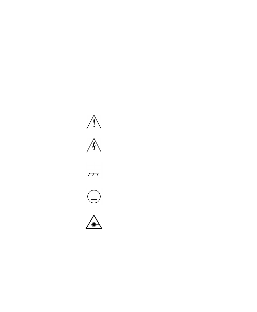
6DIHW\6\PEROV
&DXWLRQUHIHUWRDFFRPSDQ\LQJGRFXPHQWV
:DUQLQJULVNRIHOHFWULFVKRFN
)UDPHRUFKDVVLVWHUPLQDO
3URWHFWLYHHDUWKJURXQGWHUPLQDO
+D]DUGRXVODVHUUDGLDWLRQ
Page 8

$ERXW7KLV0DQXDO
7KH6WUXFWXUHRIWKLV0DQXDO
This manual is divided into 4 parts:
• Chapter 1 tells you how to set up your Attenuator.
• Chapters 2 to 6 shows you what you can do with your Attenuator.
• Chapters 7 to 9 show you how you can remotely program your
Attenuator, using GPIB commands.
• The appendices contain additional information not required for
routine day-to-day use.
Page 9

6HUYLFHDQG6XSSRUW
Any adjustment, maintenance, or repair of this product must be
performed by qualified personnel. Contact your customer engineer
through your local Agilent Technologies Service Center. You can
find a list of local service representatives on the Web at:
http://www.agilent-tech.com/services/English/index.html
If you do not have access to the Internet, one of these centers can
direct you to your nearest representative:
8QLWHG6WDWHV 7HVWDQG0HDVXUHPHQW&DOO&HQWHU
7ROOIUHHLQ86
&DQDGD
(XURSH
-DSDQ 0HDVXUHPHQW$VVLVWDQFH&HQWHU
)$;
/DWLQ$PHULFD
)$;
$XVWUDOLD1HZ
=HDODQG
$VLD3DFLILF
$XVWUDOLD
1HZ=HDODQG
)$;
Page 10

Page 11

Table of Contents
1 Getting Started
1.1 Using the Attenuator ..............................................29
Using the Modify Keys ...................................................... 29
1.2 Making an Attenuation Sweep ..............................30
Making an Automatic Sweep ............................................ 30
1.3 The Manual Sweep .................................................31
1.4 Using your Attenuator as a Variable Back Reflector
32
1.5 Using the Through-Power Mode ..........................33
1.6 Selecting the Wavelength Calibration and Its Function
33
2 Using the Attenuator
2.1 Setting Up the Hardware ......................................37
2.2 Setting Up the Attenuation .....................................38
Entering the Attenuation Factor ........................................ 38
Entering a Calibration Factor ............................................ 39
Entering the Wavelength ............................ ..... .................. 40
2.3 Example, Setting the Calibration ..........................42
3 Making an Attenuation Sweep
3.1 Configuring the Hardware ....................................47
11
Page 12

Table of Contents
3.2 The Automatic Sweep ............................................48
Setting Up an Automatic Sweep ........................................48
Executing the Automatic Sweep ........................................50
3.3 The Manual Sweep .................................................51
Setting Up a Manual Sweep ...............................................51
Executing the Manual Sweep .............................................53
3.4 Example, an Automatic Attenuation Sweep .........54
4 Using your Attenuator as a Variable Back Re-
flector
4.1 Configuring the Hardware ....................................59
4.2 Setting Up the Software .........................................60
Editing the Setup .................................................................60
Executing the Back Reflector Application .........................61
4.3 Example, Setting a Return Loss ............................62
5 Setting Up the System
5.1 Setting the GPIB Address .....................................67
Resetting the GPIB Address ...............................................67
5.2 Selecting the Wavelength Calibration and Its Function
67
Setting the Function of the Wavelength Calibration ..........68
Selecting the Wavelength Calibration Data .......................69
12
Page 13

Table of Contents
5.3 Selecting the Through-Power Mode .....................70
Deselecting the Through-Power Mode ............................... 71
Resetting the Through-Power Mode .................................. 71
5.4 Setting the Display Brightness ..............................71
Resetting the Display Brightness .......................................71
5.5 Selecting the Setting used at Power-On ...............72
Resetting the Power-On Setting ........................................ 72
5.6 Locking Out ENB/DIS .............................................72
Resetting the ENB/DIS Lock Out ....................................... 73
5.7 Selecting the Shutter State at Power On ..............73
Resetting the Shutter State at Power On ............................ 73
5.8 Setting the Display Resolution ..............................74
Resetting the Display Resolution ...................................... 74
6 Storing and Recalling Settings
6.1 Storing the Setting .................................................77
6.2 Recalling a Setting ..................................................77
Resetting the Instrument .................................................... 77
Recalling a User Setting .................................................... 77
7 Programming the Attenuator
7.1 GPIB Interface .......................................................81
7.2 Setting the GPIB Address .....................................83
13
Page 14

Table of Contents
7.3 Returning the Instrument to Local Control ........83
7.4 How the Attenuator Receives and Transmits Messages
83
How the Input Queue Works ..............................................83
The Output Queue ..............................................................84
The Error Queue .................................................................84
7.5 Some Notes about Programming and Syntax Diagram
Conventions ..................................................................85
Short Form and Long Form ................................................85
Command and Query Syntax .............................................86
8 Remote Commands
8.1 Units ........................................................................89
8.2 Command Summary ..............................................89
8.3 The Common Commands .....................................93
Common Status Information ..............................................93
*CLS ...................................................................................95
*ESE ............................. ......................................................95
*ESR? .................................................................................. 96
*IDN? .................................................................................97
*OPC ..................................................................................98
*OPT? ................................................................................98
*RCL ..................................................................................99
*RST ..................................................................................99
*SAV ..................................................................................100
*SRE ..................................................................................101
*STB? .................................................................................102
14
Page 15

Table of Contents
*TST? ................................................... ...... ..... .................. 103
*WAI ................................................................................. 104
8.4 DISPlay Commands ................................................104
:DISPlay:BRIGhtness ............................................ ...... ..... .104
:DISPlay:ENABle .............................................................. 105
8.5 INPut Commands ...................................................106
:INPut:ATTenuation .......................................................... 106
:INPut:LCMode ................................................................. 107
:INPut:OFFSet ................................................................... 107
:INPut:OFFSet:DISPlay .................................................... 108
:INPut:WAVelength .......................................................... 109
8.6 OUTPut Commands ...............................................110
:OUTPut:APMode ............................................................. 110
:OUTPut:POWer ............................................................... 112
:OUTPut:[:STATe] ............................................................ 113
:OUTPut:[:STATe]:APOWeron ........................................114
8.7 STATus Commands ...............................................114
:STATus:OPERation:CONDition? ....................................116
:STATus:OPERation:ENABle .......................................... 117
:STATus:OPERation[:EVENt]? ........................................ 117
:STATus:OPERation:NTRansition ................................... 118
:STATus:OPERation:PTRansition .................................... 118
:STATus:QUEStionable:CONDition? ...............................119
:STATus:QUEStionable:ENABle ..................................... 119
:STATus:QUEStionable[:EVENt]? ................................... 120
:STATus:QUEStionable:NTRansition .............................. 1 20
:STATus:QUEStionable:PTRansition ............................... 121
:STATus:PRESet ........... ...... ...... ........................................122
8.8 SYSTem Commands ...............................................122
15
Page 16

Table of Contents
:SYSTem:ERRor? ..............................................................122
8.9 User Calibration Commands .................................123
Entering the User Calibration Data ....................................123
9 Programming Examples
9.1 Example 1 - Checking Communication ................131
9.2 Example 2 - Status Registers and Queues ............132
9.3 Example 3 - Measuring and Including the Insertion
Loss .................................................................................135
9.4 Example 4 - Running an Attenuation Sweep ........139
A Installation
A.1 Safety Considerations ...........................................143
A.2 Initial Inspection ...................................................143
A.3 AC Line Power Supply Requirements ................144
Line Power Cable ...............................................................144
Replacing the Battery .........................................................146
Replacing the Fuse .............................................................146
A.4 Operating and Storage Environment ...................148
Temperature ........................................................................148
Humidity ............................................................................148
Instrument Positioning and Cooling ...................................148
A.5 Switching on the Attenuator .................................149
16
Page 17

Table of Contents
A.6 Monitor Output ......................................................149
A.7 Optical Output ......................................................150
Disabling the Optical Output ............................................. 150
A.8 GPIB Interface ......................................................150
Connector ........................................................................... 151
GPIB Logic Levels ......................... ................................... 152
A.9 Claims and Repackaging .......................................152
Return Shipments to Agilent Technologies ........................ 152
B Accessories
B.1 Instrument and Options .......................................157
B.2 GPIB Cables and Adapters ..................................157
B.3 Connector Interfaces and Other Accessories ......158
Straight Contact Connector ................................................158
Option 201, Angled Contact Connector ............................. 160
C Specifications
C.1 Definition of Terms ...............................................165
C.2 Specifications ..........................................................167
Supplementary Performance Characteristics ...................... 169
C.3 Other Specifications ...............................................171
C.4 Declaration of Conformity ....................................172
17
Page 18

Table of Contents
D Performance Tests
D.1 Equipment Required .............................................175
D.2 Test Record .............................................................177
D.3 Test Failure .............................................................177
D.4 Instrument Specification .......................................177
D.5 Performance Test ...................................................178
I. Total Insertion Loss Test .................................................179
II. Linearity/Attenuation Accuracy Test .............................182
III. Attenuation Repeatability Test ......................................184
IV. Return Loss Test ...........................................................185
D.6 V. Polarization Dependent Loss (PDL): Optional 191
Polarization Dependant Loss Test (Mueller method) .........192
E Cleaning Information
Cleaning Instructions for this Instrument ............................248
E.1 Safety Precautions ..................................................249
E.2 Why is it important to clean optical devices ? .....249
E.3 What do I need for proper cleaning? ...................250
Standard Cleaning Equipment .............................................250
Additional Cleaning Equipment ..........................................253
E.4 Preserving Connectors ...........................................256
Making Connections ...........................................................256
Dust Caps and Shutter Caps ................................................256
Immersion Oil and Other Index Matching Compounds ......256
18
Page 19

Table of Contents
E.5 Cleaning Instrument Housings .............................257
E.6 Which Cleaning Procedure should I use ? ...........257
Light dirt ............................................................................. 257
Heavy dirt ........................................................................... 257
E.7 How to clean connectors ........................................258
Preferred Procedure .............. ..............................................258
Procedure for Stubborn Dirt ...............................................258
An Alternative Procedure ...................... ............................. 259
E.8 How to clean connector adapters ..........................259
Preferred Procedure .............. ..............................................259
Procedure for Stubborn Dirt ...............................................260
E.9 How to clean connector interfaces ........................260
Preferred Procedure .............. ..............................................260
Procedure for Stubborn Dirt ...............................................261
E.10 How to clean bare fiber adapters ........................261
Preferred Procedure .............. ..............................................261
Procedure for Stubborn Dirt ...............................................262
E.11 How to clean lenses ...............................................262
Preferred Procedure .............. ..............................................262
Procedure for Stubborn Dirt ...............................................263
E.12 How to clean instruments with a fixed connector inter-
face ..................................................................................263
E.13 How to clean instruments with an optical glass plate
264
E.14 How to clean instruments with a physical contact in-
terface .............................................................................264
Preferred Procedure .............. ..............................................265
Procedure for Stubborn Dirt ...............................................265
19
Page 20

Table of Contents
E.15 How to clean instruments with a recessed lens inter-
face ..................................................................................265
Preferred Procedure .................................................... ...... ...266
Procedure for Stubborn Dirt ................................................266
E.16 How to clean optical devices which are sensitive to me-
chanical stress and pressure .........................................267
Preferred Procedure .................................................... ...... ...267
Procedure for Stubborn Dirt ................................................267
Alternative Procedure ............................................ ..... ...... ...267
E.17 How to clean metal filters or attenuator gratings 268
Preferred Procedure .................................................... ...... ...268
Procedure for Stubborn Dirt ................................................268
E.18 Additional Cleaning Information .......................268
How to clean bare fiber ends ...............................................269
How to clean large area lenses and mirrors .........................269
Preferred Procedure .................................................... ...... ...269
Procedure for Stubborn Dirt ................................................270
Alternative Procedure A .................................. ...... ..... .........270
Alternative Procedure B ......................................................271
E.19 Other Cleaning Hints ...........................................271
Making the connection ........................................................271
Lens cleaning papers ...........................................................271
Immersion oil and other index matching compounds .........272
Cleaning the housing and the mainframe ............................272
F Error messages
F.1 Display Messages ...................................................275
20
Page 21

Table of Contents
F.2 GPIB Messages .......................................................276
Command Errors .................................................................276
Execution Errors ..................................................... ............ 280
Device-Specific Errors ....................................................... 281
Query Errors ....................................................................... 282
Instrument Specific Errors .................................................. 283
21
Page 22

Table of Contents
22
Page 23

List of Figures
Figure 1-1 The Attenuator Keys ................................................................................ 29
Figure 1-2 The Modify Keys ..................................................................................... 30
Figure 1-3 The Parameters for an Automatic Sweep ................................................. 31
Figure 1-4 The Hardware Configuration for the Back Reflector (Options 201 and 203) 32
Figure 2-1 The Hardware Configuration for the Attenuator ...................................... 37
Figure 2-2 The Attenuation Factor on the Display .................................................... 38
Figure 2-3 The Calibration Factor on the Display ..................................................... 39
Figure 2-4 The Wavelength on the Display ............................................................... 41
Figure 2-5 Hardware Configuration for Attenuation Example - A ........................... 42
Figure 2-6 Hardware Configuration for Attenuation Example - B ............................ 43
Figure 3-1 The Hardware Configuration for the Attenuator ...................................... 47
Figure 3-2 The Parameters for an Automatic Sweep ................................................. 49
Figure 3-3 Selecting the Automatic Sweep Application ........................................... 49
Figure 3-4 Running the Automatic Sweep ................................................................ 51
Figure 3-5 Editing the STOP Parameter .................................................................... 52
Figure 3-6 Running the Manual Sweep ..................................................................... 53
Figure 4-1 The Hardware Configuration for the Back Reflector ............................... 59
Figure 4-2 Editing the Value for the Reference Return Loss .................................... 61
Figure 4-3 Executing the Back Reflector Application ............................................... 62
Figure 4-4 Hardware Configuration for Variable Return Loss .................................. 63
Figure 5-1 The LAMBDCAL Indicator on the Display ................................................ 68
Figure 5-2 The USERCAL Indicator on the Display .................................................. 69
Figure 5-3 The Display in Through-Power Mode ..................................................... 70
Figure 6-1 The Display when Recalling the Default Setting ..................................... 77
Figure 8-1 Common Status Registers ........................................................................ 94
Figure 8-2 The Status Registers ................................................................................. 116
Figure 9-1 Hardware Configuration for Attenuation Example - A ........................... 135
Figure 9-2 Hardware Configuration for Attenuation Example - B ............................ 136
Figure A-1 Line Power Cables - Plug Identification ................................................. 144
Figure A-2 Rear Panel Markings ............................................................................... 145
Figure A-3 Releasing the Fuse Holder ...................................................................... 147
Figure A-4 The Fuse Holder ...................................................................................... 147
Figure A-5 Correct Positioning of the Attenuator ..................................................... 149
Figure A-6 GPIB Connector ...................................................................................... 151
Figure B-1 Straight Contact Connector Configuration .............................................. 159
23
Page 24

List of Figures
Figure B-2 Angled Contact Connector Configuration .............................................. 160
Figure D-1 Total Insertion Loss Test Setup 1, Options 100, 101, 121 ...................... 179
Figure D-2 Total Insertion Loss Test Setup 1, Options 201, 221 .............................. 180
Figure D-3 Total Insertion Loss Test Setup 1, Option 350 ....................................... 180
Figure D-4 Total Insertion Loss Test Setup 2, Options 100, 101, 121 ...................... 181
Figure D-5 Total Insertion Loss Test Setup 2, Options 201, 221 .............................. 181
Figure D-6 Total Insertion Loss Test Setup 2, Option 350 ....................................... 182
Figure D-7 Return Loss Test Setup 1, Options 100, 101, 121 .................................. 185
Figure D-8 Return Loss Test Setup 2, Options 100, 101 .......................................... 187
Figure D-9 Return Loss Test Setup 2, Option 121 .................................................... 187
Figure D-10 Return Loss Test Setup 1, Options 201, 221 ........................................ 188
Figure D-11 Return Loss Test Setup 2, Option 201 .................................................. 189
Figure D-12 Return Loss Test Setup 2, Option 221 .................................................. 190
Figure D-13 PDL Test Setup 1: Reference Measurement ......................................... 192
Figure D-14 PDL Test Setup 2: Power after DUT .................................................... 198
24
Page 25

List of Tables
Table 7-1 GPIB Capabilities ...................................................................................... 82
Table 8-1 Units and Allowed Mnemonics ................................................................. 89
Table 8-2 Common Command Summary .................................................................. 89
Table 8-3 Command List ........................................................................................... 90
Table 8-4 The Event Status Enable Register .............................................................. 96
Table 8-5 The Standard Event Status Register........................................................... 97
Table 8-6 Reset State (Default Setting) ..................................................................... 100
Table 8-7 The Service Request Enable Register ........................................................ 101
Table 8-8 The Status Byte Register............................................................................ 102
Table 8-9 The Self Test Results.................................................................................. 103
Table A-1 Temperature .............................................................................................. 148
Table C-1 Specifications - Options 100, 101 and 201................................................ 167
Table C-2 Monitor Output Options ........................................................................... 168
Table C-3 Multimode Options ................................................................................... 169
Table D-1 Equipment Required for the Agilent 8156A (1310/1550nm) ................... 176
Table D-2 Equipment for the PDL test 1.................................................................... 191
Table D-3 Performance Test Agilent 8156A ............................................................. 200
25
Page 26

List of Tables
26
Page 27

1
1 Getting Start e d
Page 28

Getting Start e d
This chapter introduces the features of the Agilent Technologies
8156A. More detail is given on these features in the following
chapters.
The main features of the Agilent 8156A, other than its use as an
attenuator, are its built-in sweep and back reflector applications, its
through-power mode (which displays the power at the output of the
instrument, rather than the amount of attenuation set) and its
selection of wavelength calibration possibilities.
28
Page 29
Getting Started
Using the Attenuator
1.1 Using the Attenuator
NOTE Before using the instrument, you should make sure that it is properly
warmed up. The instrument is properly warmed up when it has been
switched on for a minimum of 45 minutes. Failure to do this can cause
errors of up to 0.04dB in the attenuation.
Set the attenuation of the filter using A
(wavelength), and C
Figure 1-1 The Attenuator Keys
The attenuation factor and the calibration factor set the position of
the filter. The calibration factor allows you to of fset the value of the
attenuation factor.
Att(dB) = Cal(dB) + Attenuation
In addition, you can use D
attenuation factor to the calibration factor.
TT (attenuation factor), λ
AL (calibration factor).
(dB)
filter
ISP→CAL to transfer the current
Using the Modify Keys
There are four modify keys on the front panel of the attenuator.
29
Page 30

Getting Started
Making an Attenuation Sweep
Figure 1-2 The Modify Keys
Editing a Number
Use
⇐ and ⇒ to move the cursor from digit to digit when editing a
number. Use
number.
⇑ and ⇓ to change the value of a digit when editing a
Editing a Non-Numeric Parameter
⇑ or ⇒ to increment the parameter.
Use
⇓ or ⇐ to decrement the parameter.
Use
1.2 Making an Attenuation Sweep
There are two types of attenuation sweep, automatic and manual.
Making an Automatic Sweep
An automatic sweep is one where stepping from one attenuation
factor to the next is done by the instrument.
To select the automatic sweep press SWP, and make sure that
SWEEP is set to AUTO. By pressing S
30
WP repeatedly you view and
Page 31

Getting Started
The Manual Sweep
can edit the parameters for the sweep. START is the attenuation
factor at which the sweep begins, STOP is the attenuation factor
that ends the sweep, STEP is the size of the attenuation factor
change, and DWELL is the time taken for each attenuation factor.
Figure 1-3 The Parameters for an Automatic Sweep
If you have set up your sweep, then you press E
XEC to run it.
1.3 The Manual Sweep
A manual sweep is one where stepping from one attenuation factor
to the next is done by the user.
T o select the manual sweep press SWP, and make sure that SWEEP
is set to MANUAL. By pressing S
edit the parameters for the sweep. START is the attenuation factor
at which the sweep begins, STOP is the attenuation factor that ends
the sweep, and STEP is the size of the attenuation factor change.
If you have set up your sweep, then you press E
to the next attenuation factor in the sweep, press
the previous attenuation factor in the sweep, press
31
WP repeatedly you can view and
XEC to run it. To go
⇑ or ⇒. To go to
⇓ or ⇐.
Page 32

Getting Started
Using your Attenuator as a Variable Back Reflector
1.4 Using your Attenuator as a Variable Back Reflector
NOTE Before using the instrument, you should make sure that it is properly
warmed up. The instrument is properly warmed up when it has been
switched on for a minimum of 45 minutes. Failure to do this can cause
errors of up to 0.04dB in the attenuation.
To use the attenuator as a back reflector, you need to set up the
hardware as shown in the figure below.
Figure 1-4 The Hardware Configuration for the Back Reflector (Options 201 and
203)
RL dB() 10 10
log–=
Press B
enter measured values for the insertion loss of the attenuator (INS
LOSS), the return loss of the attenuator (RL INPUT), and the
reference return loss you are using (RL REF). Th e r et urn los s ( RL)
is calculated according to the equation
RLInput dB
------------------------------------- -
()–
10
You edit the value for the return loss while the application is
running.
32
ACK REFL to start operation as a back reflector. You need to
RLInput dB()–
------------------------------------- -
110
–
+
10
10
()InsLoss dB()+()RLRef dB()+()–
2 Att dB
---------------------------------------------------------------------------------------------------------------10
Page 33

Getting Started
Using the Through-Power Mode
1.5 Using the Through-Power Mode
NOTE Before using the instrument, you should make sure that it is properly
warmed up. The instrument is properly warmed up when it has been
switched on for a minimum of 45 minutes. Failure to do this can cause
errors of up to 0.04dB in the attenuation.
In the through-power mode, the instrument shows the power that
gets through the attenuator on the display (that is the power at the
output) rather than the attenuation.
When you select the through-power mode the attenuation factor (in
dB) becomes the value for the through-power (in dBm). Set the
calibration factor (see “Entering a Calibration Factor” on page 39)
to get the attenuation factor to the value of the through-power.
After measuring and setting this base power value, press S
repeatedly until THRUPOWR is shown at the bottom of the display.
Select ON to select the through-power mode.
Edit the through-power factor by pressing A
Modify key s .
TT, and then the
YST
1.6 Selecting the Wavelength Calibration and Its Function
The attenuation at any point on the filter is wavelength dependent.
This dependence is measured and stored in the instrument, and is
used, with the value for the wavelength entered by the user to
compensate for the dependence. This is the wavelength calibration
data.
There are two ways in which this data can be used:
33
Page 34

Getting Started
Selecting the Wavelength Calibration and Its Function
• to reposition the filter so that the attenuation stays constant, or
• to change the attenuation factor on the display to show the
wavelength dependence. You use this to set the wavelength for
an unknown source (you alter the wavelength until the displayed
attenuation matches the measured attenuation).
To set the function of the calibration data press S
YST repeatedly
until LAMBDCAL is shown at the bottom of the display. Set
LAMBDCAL to OFF to use the calibration data to reposition the
filter, and set LAMBDCAL to ON to use the calibration data to
change the attenuation factor.
As well as the wavelength calibration data measured for and stored
in your instrument in the factory, there is space reserved in memory
for a set of your own user calibration data. (You load this data into
the instrument over the GPIB. See “User Calibration Commands”
on page 123)
YST repeatedly until USERCAL is shown at the bottom of the
Press S
display. OFF selects the factory-made wavelength calibration data.
ON selects the user wavelength calibration data.
34
Page 35

2
2 Using the Attenuator
Page 36

Using the Attenuator
This chapter describes the use of the Agilent Technologies 8156A
as an attenuator. There is an example given at the end of this
chapter.
36
Page 37

Using the Attenuator
Setting Up the Hardware
2.1 Setting Up the Hardware
To use the attenuator, you need to set up the hardware as shown in
the figure below.
Figure 2-1 The Hardware Configuration for the Attenuator
NOTE Before using the instrument, you should make sure that it is properly
warmed up. The instrument is properly warmed up when it has been
switched on for a minimum of 45 minutes. Failure to do this can cause
errors of up to 0.04dB in the attenuation.
The connector interface you need depends on the connector type
you are using (see “Connector Interfaces and Other Accessories”
on page 158).
If you have option 121 or option 221, then the Monitor Output
provides a signal for monitoring the power getting through the
attenuator. The signal level is approximately 5% of the output
power level. For the most accurate results, you should measure the
coupling ratio, and its wavelength dependence, for the Monitor
Output yourself.
37
Page 38

Using the Attenuator
Setting Up the Attenuation
2.2 Setting Up the Attenuation
The attenuation can be set in two different ways. This section
describes how to set the attenuation by specifying the attenuation
factor and an offset (called a calibration factor).
“Selecting the Through-Power Mode” on page 70 describes how to
set the attenuation by specifying the power that gets through.
Entering the Attenuation Factor
The attenuation factor is shown at the top left of the display.
Figure 2-2 The Attenuation Factor on the Display
Edit the attenuation factor using the modify keys.
The filter attenuation is changed while you edit the attenuation
factor according to the equation:
(dB) = Att(dB) - Cal (dB)
Att
filter
To edit the attenuation factor,
1. press A
2. edit the factor using the Modify keys (see “Using the Modify
38
TT, and
Keys” on page 29).
Page 39

Using the Attenuator
Setting Up the Attenuation
Resetting the Attenuation Factor
To reset the attenuation factor, press and hold A
resets (this takes approximately two seconds). The attenuation
factor resets so that the filter attenuation is zero, that is
Att(dB) = Cal(dB)
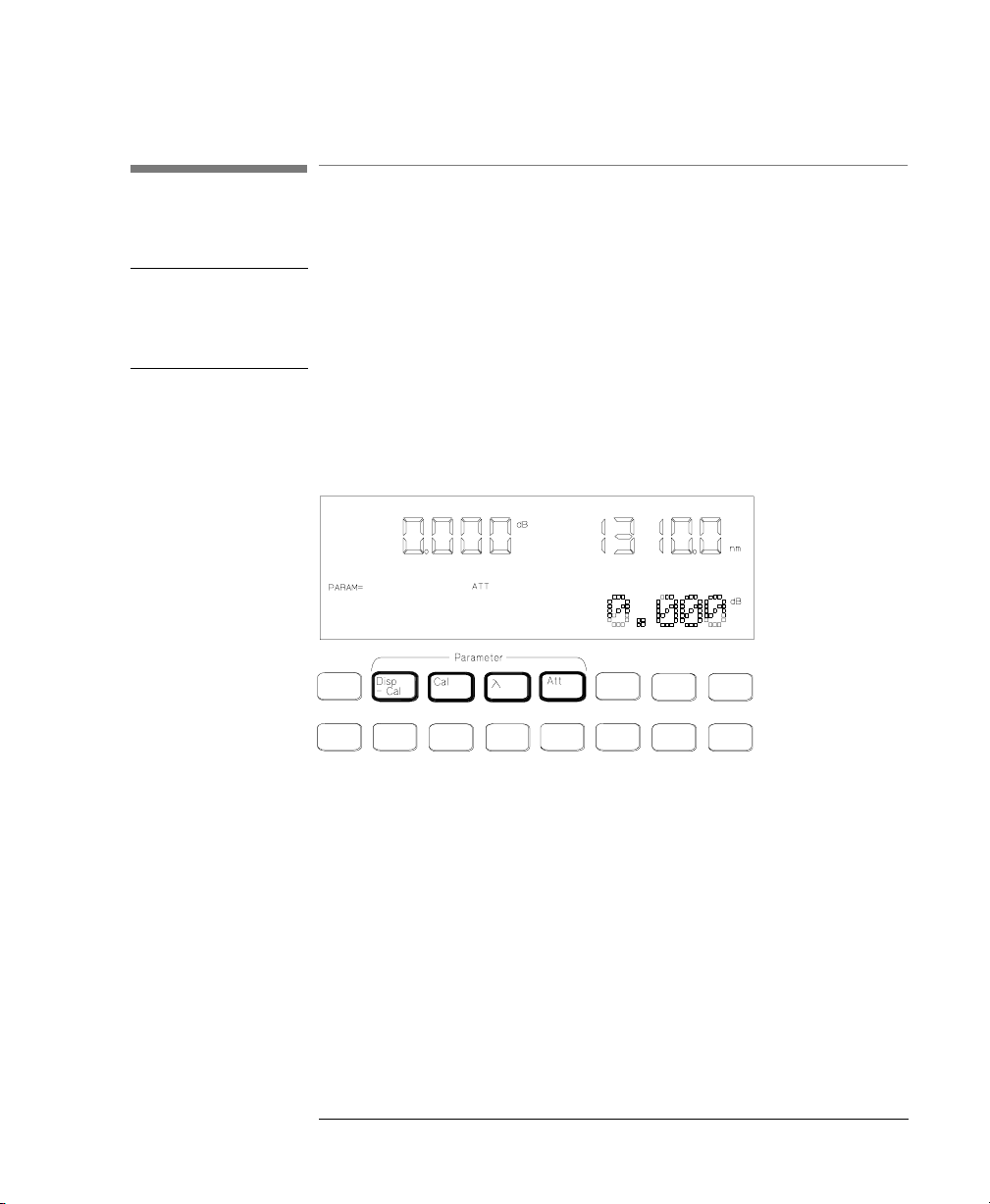
Entering a Calibration Factor
The calibration factor is shown at the bottom left of the display
Figure 2-3 The Calibration Factor on the Display
This factor does not affect the filter attenuation. It is used to offset
the values for the attenuation factor.
There are two ways of entering the calibration factor.
• by editing, and
• by transferring
TT until the value
Att
NEW
(dB) = Att
(dB) + Cal
filter
Editing the Calibration Factor
You would use this, for example, to enter an offset to compensate
for the insertion loss (attenuation) of your hardware setup.
The filter attenuation stays constant while you edit the calibration
factor. This means that the attenuation factor, shown on the display ,
changes according to the formula below (from equation (1)):
(dB) = Att
NEW
OLD
(dB) -Cal
(dB) + Cal
OLD
NEW
(dB)
To edit an external calibration factor,
39
Page 40

Using the Attenuator
Setting Up the Attenuation
1. press CAL, and
2. edit the factor using the Modify keys (see “Using the Modify
Keys” on page 29).
Resetting the Calibration Factor To reset the calibration factor, press and hold C
AL until the value
resets to zero (this takes approximately two seconds). The
calibration factor resets to zero.
Transferring to the Calibration Factor
You can transfer the attenuation factor shown on the display into
the calibration factor, so that the attenuation factor is reset to zero.
You would use this, for example, after you have set the power
through the attenuator at a specific level. When you have reset the
attenuation factor, you can edit it to get a relative attenuation.
The filter attenuation stays constant when you transfer to the
calibration factor. This means that the new calibration factor is
calculated from the attenuation factor and the old calibration factor
according to the formula below (from equation (1)):
Cal
(dB) = -Att
NEW
To transfer to the calibration factor, press D
(dB) = Cal
filter
OLD
(dB) - Att
ISP→CAL.
OLD
(dB)
Entering the Wavelength
The attenuation at any point on the filter is wavelength dependent.
This dependence is measured and stored in the instrument, and is
used, with the value for the wavelength entered by the user, to
compensate for the dependence. This is the wavelength calibration
data.
NOTE There are two ways of using the wavelength calibration data,
• to reposition the filter so that the attenuation stays constant, or
• to change the attenuation factor on the display to show the
wavelength dependence. You use this to set the wavelength for an
40
Page 41

Using the Attenuator
Setting Up the Attenuation
unknown source (you alter the wavelength until the displayed
attenuation matches the mea sured attenuation).
There are two sets of wavelength calibration data, one made in the
factory, individually, for your instrument. The user defines the other.
For more details on these topics, see “Selecting the Wavelength
Calibration and Its Function” on page 67.
The wavelength is shown at the top right of the display.
Figure 2-4 The Wavelength on the Display
Edit the wavelength using the modify keys.
To edit the wavelength,
1. press
λ, and
2. edit the value using the Modify keys (see “Using the Modify
Keys” on page 29).
Resetting the Wavelength To reset the wavelength, press and hold A
TT until the value resets
(this takes approximately two seconds). The wavelength resets to
1310nm.
41
Page 42

Using the Attenuator
Example, Setting the Calibration
2.3 Example, Setting the Calibration
This example uses the Agilent 8156A Attenuator, with a HP 8153A
multimeter with one source and one sensor. The connectors for this
system are all HMS-10.
We set up the hardware, and measure the insertion loss of the
system and use this value to set a calibration factor.
1. Configure the hardware as shown in the figure below, making
sure that all the connectors are clean:
Figure 2-5 Hardware Configuration for Attenuation Example - A
a. Make sure that the power sensor is inst alled in the
multimeter mainframe in channel A, and the source is in
channel B.
b. Connect both instruments to the electric supply.
c. Switch on both instruments.
42
Page 43

Using the Attenuator
Example, Setting the Calibration
NOTE Under normal circumstances you should leave the instruments to
warmup. (The multimeter needs around 20 minutes to warmup. The
attenuator needs around 45 minutes with the shutter open to warmup.)
Warming up is necessary for accuracy of the sensor, and the output
power of the source.
d. Connect a patchcord from the source to the input of the
sensor.
2. Measure the insertion loss of the Hardware setup:
a. On the multimeter:
i. Set the wavelength for the sensor to that of the source.
ii. Activate the source, by pressing the gray button on its
front panel.
iii. Start the loss application (press M
XEC).
and E
ODE and then LOSS,
b. Reconfigure the hardware to include the attenuator:
i. Disconnect the source from the sensor, and connect it to
the input of the attenuator.
Figure 2-6 Hardware Configuration for Attenuation Exam ple - B
ii. Connect a patchcord from the output of the attenuator to
the sensor.
43
Page 44

Using the Attenuator
Example, Setting the Calibration
c. Set the wavelength on the attenuator to that of the source:
i. Press
λ.
ii. Use the m odif y keys to edit the value for the
wavelength.
d. Reset the calibration factor, by pressing and holding C
AL
for two seconds.
e. Reset the attenuation factor, by pressing and holding ATT
for two seconds.
f. Enable the output of the attenuator (press ENB/DIS so that
the LED lights).
g. Note the value for the loss read by the multimeter.
3. Enter the insertion loss of the hardware setup.
a. Press C
AL.
b. Edit the calibration factor so that it has the value shown on
the multimeter display, using the modify keys.
You should notice that the value for the attenuation factor changes,
and always has the same value as that for the calibration factor. This
is because the filter attenuation stays at zero (you should also notice
that the display on the multimeter does not change).
The attenuator now shows its full attenuation (including its own
insertion loss) on the display.
44
Page 45

3
3 Making an Attenuation
Sweep
Page 46

Making an Attenuation
Sweep
This chapter describes how to make an attenuation sweep with the
Agilent T echnologies 8156A Attenuator. An example is given at the
end of the chapter.
46
Page 47

Making an Attenuation Sweep
Configuring the Hardware
3.1 Configuring the Hardware
To use the attenuator for a sweep, you need to set up the hardware
as shown in the figure below. (This is the configuration as giv en for
simple attenuation in chapter 2).
Figure 3-1 The Hardware Configuration for the Attenuator
NOTE Before using the instrument, you should make sure that it is properly
warmed up. The instrument is properly warmed up when it has been
switched on for a minimum of 45 minutes. Failure to do this can cause
errors of up to 0.04dB in the attenuation.
The connector interface you need depends on the connector type
you are using (see “Connector Interfaces and Other Accessories”
on page 158).
If you have option 121 or option 221 (the monito r outpu t ), then th e
Monitor Output provides a signal for monitoring the power getting
through the attenuator. The signal level is approximately 5% of the
output power level. For the most accurate results, you should
measure the coupling ratio, and its wavelength dependence, for the
Monitor Output yourself.
47
Page 48

Making an Attenuation Sweep
The Automatic Sweep
3.2 The Automatic Sweep
An automatic sweep is one where stepping from one attenuation
factor to the next is done by the instrument.
Setting Up an Automatic Sweep
There are four parameters for the automatic sweep
• START is the attenuation factor at which the sweep begins.
• STOP is the attenuation factor that ends the sweep. If START
and STEP are such that the sweep does not end exactly at
STOP, then the sweep ends at the immediately previous value.
• STEP is the size of the attenuation factor change. This value is
always positive, even for a sweep of decreasing attenuation
factor. STEP cannot be set to a value greater than the difference
between START and STOP.
• DWELL is the time taken for each attenuation factor.
NOTE The dwell time includes the time it takes for the filter attenuation to
change. The time taken to change depends on the size of the attenuation
factor change, and is in the range 20 to 400ms (typical value is 200ms).
48
Page 49

Making an Attenuation Sweep
The Automatic Sweep
Figure 3-2 The Parameters for an Automatic Sweep
Starting the Setting Up
T o select the automatic sweep
1. Press S
2. If it is not already set, use
WP.
⇑ or ⇓ to set SWEEP to AUTO.
Figure 3-3 Selecting the Automatic Sweep Application
Editing the Parameters
To edit the value of the parameters
3. Press S
4. Edit the value of START with the Modify keys.
5. Press S
49
WP again to get START.
WP again to get STOP.
Page 50

Making an Attenuation Sweep
The Automatic Sweep
6. Edit the value of STOP with the Modify keys.
7. Press S
WP again to get STEP.
8. Edit the value of STEP with the Modify keys.
9. Press S
WP again to get DWELL.
10. Edit the value of DWELL with the Modify keys.
See “Using the Modify Keys” on page 29 for information on
editing with the Modify keys.
Resetting the Parameters
To reset any of the sweep parameters, press and hold SWP until the
value resets (this takes approximat el y two second s).
START and STOP reset so that the filter attenuation (inside th e
instrument) is zero, that is
Start = Cal
or
Stop = Cal
See “Entering a Calibration Factor” on page 39 for information
about setting the calibration factor, Cal.
STEP resets to zero.
DWELL resets to 0.2 seconds.
Executing the Automatic Sweep
If you have just set up your sweep, then you only need to press
XEC to run the application.
E
If you have already set up the sweep, and are currently operating
the instrument as an attenuator,
1. Press S
2. Press E
50
WP, and then,
XEC.
Page 51

Making an Attenuation Sweep
The Manual Sweep
Figure 3-4 Running the Automatic Sweep
If there is something wrong with a parameter (if STEP is zero, for
example), this parameter is shown on the display for editing. Edit
the parameter, and press E
Repeating the Sweep
When the sweep is finished (SWEEP READY is shown at the
bottom of the display), you can press E
Restarting the Sweep
XEC again.
XEC to start it again.
To restart the sweep at any time while it is runnin g, p ress EXEC.
3.3 The Manual Sweep
A manual sweep is one where stepping from one attenuation factor
to the next is done by the user.
Setting Up a Manual Sweep
There are three parameters for a manual sweep
• START is the attenuation factor at which the sweep begins.
• STOP is the attenuation factor that ends the sweep. If START
and STEP are such that the sweep does not end exactly at STOP,
then the sweep ends at the immediately previous value.
51
Page 52

Making an Attenuation Sweep
The Manual Sweep
• STEP is the size of the attenuation factor change. This value is
always positive, even for a sweep of decreasing attenuation
factor. STEP cannot be set to a value greater than the difference
between START and STOP.
Starting the Setting Up
T o select the manual sweep
1. Press S
WP.
2. If it is not already set, use the modify keys to set SWEEP to
MANUAL.
Editing the Parameters
To edit the value of the parameters
3. Press S
4. Edit the value of START with the Modify keys.
5. Press S
6. Edit the value of STOP with the Modify keys.
Figure 3-5 Editing the STOP Parameter
7. Press S
WP again to get START.
WP again to get STOP.
WP again to get STEP.
8. Edit the value of STEP with the Modify keys.
See “Using the Modify Keys” on page 29 for information on
editing with the Modify keys.
52
Page 53

Making an Attenuation Sweep
The Manual Sweep
Resetting the Parameters
T o res et any of the sweep parameters, press and hold SWP until the
value resets (this takes approximat el y two second s).
START and STOP reset so that the filter attenuation (inside the
instrument) is zero, that is
Start = Cal
or
Stop = Cal
See “Entering a Calibration Factor” on page 39 for information
about setting the calibration factor, Cal.
STEP resets to zero.
Executing the Manual Sweep
If you have just set up your sweep, then you only need to press
XEC to run the application.
E
If you have already set up the sweep, and are currently operating
the instrument as an attenuator,
1. Press S
2. Press E
WP, and then,
XEC.
Figure 3-6 Running the Manual Sweep
If there is something wrong with a parameter (if STEP is zero, for
example), this parameter is shown on the display for editing. Edit
the parameter, and press E
53
XEC again.
Page 54

Making an Attenuation Sweep
Example, an Automatic Attenuation Sweep
Changing the Attenuation in a Manual Sweep
To go to the next attenuation factor in the sweep, press ⇑ or ⇒.
To go to the previous attenuation factor in the sweep, press
⇓ or ⇐.
3.4 Example, an Automatic Attenuation Sweep
This example uses the Agilent 8156A Attenuator on its own.
W e set up the instrument to sweep from 5dB to 0dB with an interval
of 0.5dB, dwelling for a second at each attenuation factor.
1. First we want to reset the instrument.
NOTE If someone else is using this instrument, please check with them before
resetting, or store their setting for later recall.
a. Press R
b. Press E
2. Start the automatic sweep application.
a. Press S
b. If the sweep parameter is set to MANUAL, press
it to AUTO.
ECALL.
XEC.
WP.
⇑, or ⇓ to set
3. Set the start attenuation factor.
a. Press S
WP.
b. Use the Modify keys to set START to 5.000dB.
4. Set the attenuation factor step size.
a. Press S
WP, to get the stop parameter. We do not need to edit
this parameter.
b. Press SWP to get the step parameter.
54
Page 55

Making an Attenuation Sweep
Example, an Automatic Attenuat ion Sweep
c. Use the Modify keys to set STEP to 0.500dB.
5. Set the dwell time.
a. Press S
WP.
b. Use the Modify keys to set DWELL to 1.00s.
6. Execute the sweep
a. Press S
WP.
b. Make sure the output is enabled (press E
LED lights).
c. Press EXEC.
NB/DIS until the
55
Page 56

Making an Attenuation Sweep
Example, an Automatic Attenuation Sweep
56
Page 57

4
4 Using your Attenuator as a
Variable Back Reflector
Page 58

Using your Attenuator
as a Variable Back
Reflector
This chapter describes how you can use your attenuator as a
variable back reflector. An example using the back reflector kit
(option 203 with option 201) is given at the end of the chapter.
58
Page 59

Using your Attenuator as a Variable Back Reflector
Configuring the Hardware
4.1 Configuring the Hardware
To use the attenuator as a back reflector, you need to set up the
hardware as shown in the figure below.
NOTE If this your first time to use the att enuat or as a back r ef lector, you first
need to make some measurements. These require other setups before
setting up the hardware as shown below (see “Setting Up the Software”
on page 60).
Figure 4-1 The Hardware Configuration for the Back Reflector
NOTE Before using the instrument, you should make sure that it is properly
warmed up. The instrument is properly warmed up when it has been
switched on for a minimum of 45 minutes. Failure to do this can cause
errors of up to 0.04dB in the attenuation.
If you are not using option 201, the connector interfaces you need
depends on the connector type you are using. Option 121 or option
221 (the monitor output) is of no use when using the attenuator as a
back reflector. The disruption to the back r eflection performance b y
leaving this output open is negligible, though you may want to
terminate it to eliminate any small effect it might have.
59
Page 60

Using your Attenuator as a Variable Back Reflector
Setting Up the Software
4.2 Setting Up the Software
There are four factors that influence the back reflection of the
attenuator. These are
1. the insertion loss of the attenuator (INS LOSS),
2. the return loss of the attenuator (RL INPUT),
3. the reference return loss you are using (RL REF), and
4. the filter attenuation.
The return loss (RL) is calculated according to the equation
RL dB() 10 10
log–=
RLInput dB
------------------------------------- -
()–
10
You edit the values for the insertion loss, the reference return loss,
and the return loss of the attenuator while you are setting up the
application.
You edit the value for the return loss while the application is
executing. The instrument calculates and sets the req uired value for
the filter attenuation.
Editing the Setup
Before you start setting up the back reflector application, you may
need to measure the following values, if you do not already know
them:
• The insertion loss of the instrument (see “Example, Setting the
• The return loss of the instrument (with the output properly
• The reference return loss value.
RLInput dB()–
------------------------------------- -
110
–
+
10
10
()InsLoss dB()+()RLRef dB()+()–
2 Att dB
----------------------------------------------------------------------------------------------------------------
Calibration” on page 42,
terminated), and
10
60
Page 61

Using your Attenuator as a Variable Back Reflector
Setting Up the Software
To start setting up the Back Reflector application
1. Press B
ACK REFL.
After pressing this the first parameter (INS LOSS) is ready to for
editing.
2. Edit the value insertion loss with the Modify keys.
3. Press B
ACK REFL.
4. Edit the value reference return loss with the Modify keys.
Figure 4-2 Editing the Value for the Reference Return Loss
5. Press B
ACK REFL.
6. Edit the value attenuator return loss with the Modify keys.
See “Using the Modify Keys” on page 29 for information on
editing with the Modify keys.
Resetting the Parameters
T o rese t any of the back reflector parameters , press and hold BACK
EFL until the value resets (this takes approximately two seconds).
R
INS LOSS resets to 2.000dB.
RL REF resets to 14.700dB (the return loss for the glass/air
interface at an open connector)
RL INPUT resets to 60.000dB.
Executing the Back Reflector Application
If you have just set up the application, then you only need to press
XEC to run the application.
E
61
Page 62

Using your Attenuator as a Variable Back Reflector
Example, Setting a Return Loss
If you have already set up the application, and are currently
operating the instrument as an attenuator,
1. Press BACK REFL, and then,
2. Press E
Figure 4-3 Executing the Back Reflector Application
The value shown at the top left of the display is the return loss of
the instrument. You can edit the value of the return loss with the
Modify keys.
XEC.
4.3 Example, Setting a Return Loss
This example uses the Ahilent T echnolog ies 8156A Attenuator with
options 201, and 203.
Assuming an insertion loss of 2.00d B and a return los s of 60.000 dB
for the instrument we set up the instrument to have a return loss of
20dB.
62
Page 63

Using your Attenuator as a Variable Back Reflector
Example, Setting a Return Loss
1. Configure the hardware as shown in the figure below:
Figure 4-4 Hardware Configuration for Variable Return Loss
a. Connect the instrument to the electric supply.
b. Switch on the instrument.
2. Reset the instrument.
NOTE If someone else is using this instrument, please check with them before
resetting, or store their setting for later recall.
a. Press R
b. Press E
ECALL.
XEC.
3. Set the return loss reference value for the Agilent 81000BR
reference reflector.
a. Press BACK REFL twice to select the RL REF parameter.
b. Edit the value, with the Modify keys to set it to 0.180dB
4. Press E
XEC to start the application
5. Edit the return loss value, with the Modify keys, to set it to
20.000dB.
63
Page 64

Using your Attenuator as a Variable Back Reflector
Example, Setting a Return Loss
64
Page 65

5
5 Setting Up the System
Page 66

Setting Up the System
This chapter describes how to set the various system parameters for
your attenuator.
66
Page 67

Setting Up the System
Setting the GPIB Address
5.1 Setting the GPIB Address
To set the GPIB address of the attenuator
1. Press S
2. Edit the value for ADDRESS using the Modify keys.
YST.
Resetting the GPIB Address
To reset ADDRESS, press and hold SYST until the value resets (this
takes approximately two seconds).
ADDRESS resets to 28.
5.2 Selecting the Wavelength Calibration and Its Function
The attenuation at any point on the filter is wavelength dependent.
This dependence is measured and stored in the instrument, and is
used, with the value for the wavelength entered by the user to
compensate for the dependence. This is the wavelength calibration
data.
As well as the wavelength calibration data measured for and stored
in your instrument in the factory, there is space reserved in memory
for a set of your own user calibration data.
There are two choices concerning the use of waveleng th calibration
data.
• Whether or not the data should be used to position the filter to
compensate for wavelength dependence.
• Whether the factory-made wavelength calibration data is used,
or the data entered by the user.
67
Page 68

Setting Up the System
Selecting the Wavelength Calibration and Its Function
Setting the Function of the Wavelength Calibration
This compensation can be used
• to reposition the filter so that the attenuation stays constant, or
• to change the attenuation factor on the display to show the
wavelength dependence. You use this to set the wavelength for
an unknown source (you alter the wavelength until the displayed
attenuation matches the measured attenuation).
To set the function of the wavelength calibration data
1. Press S
of the display.
2. Select the wavelength calibration data function using the Modify
keys. Set LAMBDCAL to OFF so that the function of the
wavelength calibration data is not visible to the user. This keeps
the attenuation value fixed, and alters the filter position. Set
LAMBDCAL to ON to keep the filter position fixed, and for the
function of the wavelength calibration data to be visible to the
user.
While it is ON, LAMBDCAL is shown at the bottom left of the
display (U/L-CAL is shown if the USERCAL is also on).
Figure 5-1 The LAMBDCAL Indicator on the Display
YST repeatedly until LAMBDCAL is shown at the bottom
Resetting the Function of the Wavelength Calibration Data
To reset LAMBDCAL, press and hold SYST until the value resets
(this takes approximately two seconds).
LAMBDCAL resets to OFF.
68
Page 69

Setting Up the System
Selecting the Wavelength Calibration and Its Function
Selecting the Wavelength Calibration Data
You enter the user wavelength calibration data over the GPIB (see
“User Calibration Commands” on page 123).
Using your own wavelength calibration data, you can use the
attenuator to compensate for the total wavelength dependence of
your hardware configuration.
NOTE If you are using the instrument in an environment where the
temperature changes, you should not use the user wavelength
calibration data, as it lacks correction for temperature changes.
To select the wavelength calibration data to use
1. Press S
2. Select the wavelength calibration data using the Modify keys.
Figure 5-2 The USERCAL Indicator on the Display
YST repeatedly until USERCAL is shown at the bottom of
the display.
OFF means that the instrument uses the factory-made
wavelength calibration data
ON means that the user wavelength calibration data is used.
While it is ON, USERCAL is shown at the bottom left of the
display (U/L-CAL is shown if the LAMBDCAL is also on).
Resetting the Wavelength Calibration Data Set
To reset USERCAL, press and hold SYST until the value resets (this
takes approximately two seconds).
USERCAL resets to OFF.
69
Page 70

Setting Up the System
Selecting the Through-Power Mode
5.3 Selecting the Through-Power Mode
In the through-power mode, the instrument shows th e po wer that
gets through the attenuator on the display (that is the power at the
output) rather than the attenuation.
When you select the through- power mod e the attenuation facto r ( in
dB) becomes the value for the through-power (in dBm). That is, if
the attenuation factor is at 32.000dB, and you switch the absolute
power mode on, then the base value for the through-power is
32.000dBm.
Measure the power at the output of the attenuator, and then use the
calibration factor (see “Entering a Calibration Factor” on page 39)
to set the attenuation factor to the required value for use as the base
value for the through-power
= (ThrouhgPower
Cal
New
- Att) + Cal
Base
After setting the calibration factor,
1. Press S
YST repeatedly until THRUPOWR is shown at the bottom
of the display.
2. Select ON to switch on the through-power mode.
The through-power factor is shown at the upper left on the display,
and you can edit it by pressing A
“Using the Modify Keys” on page 29).
Figure 5-3 The Display in Through-Power Mode
70
Current
TT, and using the Modif y keys (see
Page 71

Setting Up the System
Setting the Display Brightness
Deselecting the Through-Power Mode
When you switch the through-power mode off, the last set
calibration factor becomes active, and the attenuation factor is set
so that the filter attenuation does not change.
1. Press S
2. Select OFF to switch off the through-power mode.
YST repeatedly until THRUPOWR is shown at the bottom
of the display.
Resetting the Through-Power Mode
To reset THRUPOWR, press and hold SYST until the value resets
(this takes approximately two seconds).
THRUPOWR resets to OFF.
5.4 Setting the Display Brightness
This parameter sets the brightness of the display. To set the
brightness,
1. Press SYST repeatedly until BRIGHT is shown at the bottom of
the display.
2. Use Modify keys to set the brightness.
Resetting the Display Brightness
To reset BRIGHT, press and hold SYST until the value resets (this
takes approximately two seconds).
BRIGHT resets to full brightness.
71
Page 72

Setting Up the System
Selecting the Setting used at Power-On
5.5 Selecting the Setting used at Power-On
This parameter selects the instrument setting that is used at poweron.
1. Press SYST repeatedly until P ON SET is shown at the bottom
of the display.
2. Use Modify keys to select the setting.
LAST is the setting that was in use when the instrument was
switched off.
DEFAULT is the default setting.
a number is the number of the setting location where the u ser has
saved a setting.
Resetting the Power-On Setting
To reset P ON SET press and hold SYST until the value resets (this
takes approximately two seconds).
P ON SET is reset to LAST.
5.6 Locking Out ENB /DIS
This selects how the shutter enabling and disabling key operates
while the instrument is being operated over the GPIB.
1. Press SYST repeatedly until SHUTTER is shown at the bottom of
the display.
2. Use Modify keys to select the setting.
NORMAL means that the shutter can be enabled and disabled as
usual with E
72
NB/DIS.
Page 73

Setting Up the System
Selecting the Shutter State at Power On
LOCKOUT means that the shutter cannot be enabled or disabled
(Local Lock Out) while the instrument is being operated over the
GPIB.
Resetting the ENB/DIS Lock Out
To reset SHUTTER, press and hold SYST until the value resets (this
takes approximately two seconds).
SHUTTER resets to NORMAL.
5.7 Selecting the Shutter State at Power On
This selects whether the shutter is open or closed at power-on.
1. Press S
2. Use Modify keys to select the setting.
YST repeatedly until SHUTTER@ PON is shown at the
bottom of the display.
DIS means that the shutter is disabled at power-on.
LAST means that the shutter is the set to the state that was in use
when the instrument was switched off.
Resetting the Shutter State at Power On
To reset SHUTTER@ PON press and hold SYST until the value
resets (this takes approximately two seconds).
SHUTTER@ PON resets to LAST.
73
Page 74

Setting Up the System
Setting the Display Resolution
5.8 Setting the Display Resolution
This parameter sets the resolution of the attenuation factor and the
calibration factor on the screen.
1. Press SYST repeatedly until RESOLUT is shown at the bottom of
the display.
2. Use Modify keys to select the setting.
1/100 sets a resolution of 0.01.
1/1000 sets a resolution of 0.001.
Resetting the Display Resolution
To reset RESOLUT, press and hold SYST until the value resets (this
takes approximately two seconds).
RESOLUT resets to 1/100.
74
Page 75

6
6 Storing and Recalling
Settings
Page 76

Storing and Recalling
Settings
This chapter describes how to store instrument settings to memory,
and how to recall them.
A setting consists of the wavelength, calibration and attenuation
factors, all the application parameters, and the system parameters
with the exceptions of the display resolution, the power on setting,
and the GPIB address and command set.
76
Page 77

Storing and Recalling Settings
Storing the Setting
6.1 Storing the Setting
To store the current instrument setting
1. Press S
2. Select the location where you want to store the setting, using the
3. Press E
TORE.
⇑ or the ⇓.
XEC.
6.2 Recalling a Setting
Resetting the Instrument
To reset the instrument, you should recall the default setting
1. Press R
Figure 6-1 The Display when Recalling the Default Setting
ECALL. The DEFAULT location is shown on the display.
2. Press E
XEC.
Recalling a User Setting
To recall a setting that is stored
77
Page 78

Storing and Recalling Settings
Recalling a Setting
1. Press RECALL.
2. Select the location from which you want to recall the setting,
using the ⇑ or the ⇓.
3. Press E
XEC.
78
Page 79

7
7 Programming the
Attenuator
Page 80

Programming the
Attenuator
This chapter gives general information on how to control the
attenuator remotely. Descriptions for the actual commands for the
attenuator are given in the following chapters. The information in
these chapters is specific to the attenuator, and assumes that you are
already familiar with programming the GPIB.
80
Page 81

Programming the Attenuator
GPIB Interface
7.1 GPIB Interface
The interface used by the attenuator is the GPIB (General Purpose
Interface Bus).
This is the interface used for communication between a controller
and an external device, such as the attenuator. The GPIB conforms
to IEEE standard 488-1978, ANSII standard MC 1.1 and IEC
recommendation 625-1.
If you are not familiar with the GPIB, then refer to the following
books:
• Hewlett-Packard Company. Tutorial Description of Hewlett-
Packard Interface Bus, 1987.
• The International Institute of Electrical and Electronics
Engineers. IEEE Standard 488.1-1987, IEEE Standard Digital
Interface for Programmable Instrumentation. New York, NY,
1987
• The International Institute of Electrical and Electronics
Engineers. IEEE Standard 488.2-1987, IEEE Standard Codes,
Formats, Protocols and Common Commands For Use with
ANSI/IEEE Std 488.1-1987. New York, NY, 1987
To obtain a copy of either of these last two documents, write to:
The Institute of Electrical and Electronics Engineers, Inc.
345 East 47th Street
New York, NY 10017
USA.
In addition, the commands not from the IEEE-488.2 standard, are
defined according to the Standard Commands for Programmable
Instruments (SCPI). For an introduction to SCPI, and SCPI
programming techniques, refer to the following documents:
• Hewlett-Packard Press (Addison-Wesley Publishing Company,
Inc). A Beginners Guide to SCPI. Barry Eppler. 1991.
81
Page 82

Programming the Attenuator
GPIB Interface
• The SCPI Consortium. Standar d Comm ands for Pr ogr ammabl e
Instruments. Published periodically by various publishers. To
obtain a copy of this manual, contact you r Agilent Technologies
representative.
The attenuator interfaces to the GPIB as defined by the IEEE
Standards 488.1 and 488.2. The table shows the interface f unctional
subset that the attenuator implements.
Table 7-1 GPIB Capabilities
Mnemonic Function
SH1 Complete source handshake capability
AH1 Complete acceptor handshake capability
T6 Basic talker; serial poll; unaddressed to talk if
L4 Basic listener; unaddressed to listen if addressed
addressed to listen
to talk; no listen only
SR1 Complete service request capability
RL1 Complete remote/local capability
PP0 No parallel poll capability
DC1 Device clear capability
DT0 No device trigger capability
C0 No controller capability
82
Page 83

Programming the Attenuator
Setting the GPIB Address
7.2 Setting the GPIB Address
You can only set the GPIB address from the front panel. See
“Setting the GPIB Address” on page 67.
The default GPIB address is 28.
7.3 Returning the Instrument to Local Control
If the instrument has been operated in remote th e only k eys yo u can
use are Locala and E
to local control. Local does not operate if local lockout has been
enabled. E
attenuator. E
LOCKOUT (see “Locking Out Enb/Dis” on page 72).
NB/DIS enables and disables the output from the
NB/DIS does not operate if SHUTTER is set to
NB/DIS. The Local key returns the instrument
7.4 How the Attenuator Receives and Transmits Messages
The attenuator exchanges messages using an input and an output
queue. Error messages are kept in a separate error queue.
How the Input Queue Works
The input queue is a FIFO queue (first-in first-out). Incoming bytes
are stored in the input queue as follows:
1. Receiving a byte:
a. Clears the output queue.
83
Page 84

Programming the Attenuator
How the Attenuator Receives and Transmits Messages
b. Clears Bit 7 (MSB).
2. No modification is made inside strings or binary blocks. Outsi de
strings and binary bl ocks, the foll owing modi fications are made:
a. Lower-case characters are converted to upper-case.
b. The characters 00
to spaces (20
to 0916 and 0B16 to 1F16 are converted
16
).
16
c. Two or more blanks are truncated to one.
3. An EOI (End Or Identify) sent with any character is put into the
input queue as the character followed by a line feed (LF, 0A
).
16
If EOI is sent with a LF, only one LF is put into the input queue.
4. The parser starts if the LF character is received or if the input
queue is full.
Clearing the Input Queue
Switching the power off, or sending a Device Interface Clear signal,
causes commands that are in the input queue, but have not been
executed to be lost.
The Output Queue
The output queue contains responses to query messages. The
attenuator transmits any data from the output queue when a
controller addresses the instrument as a talker.
Each response message ends with a LF (0A
no query is received, or if the query has an error, the output queue
remains empty.
), with EOI=TRUE. If
16
The Message Available bit (MAV, bit 4) is s e t in the Statu s B yte
register whenever there is data in the output queue.
The Error Queue
The error queue is 30 errors long. It is a FIFO queue (first-in firstout). That is, the first error read is the oldest error to have occurred.
A new error is only put into the queue if it is not already in it.
84
Page 85

Programming the Attenuator
Some Notes about Programming and Syntax Diagr am
Conventions
If more than 29 errors are put into the queue, the message ’-350
<Queue Overflow>’ is placed as the last message in the queue.
7.5 Some Notes about Programming and Syntax Diagram Conventions
A program message is a message containing commands or queries
that you send to the attenuator. The following are a few points about
program messages:
• You can use either upper-case or lower-case characters.
• You can send several commands in a single message. Each
command must be separated from the next one by a semicolon
(;).
• You end a program message with a line feed (LF) character, or
any character sent with End-Or-Identify (EOI).
• You can use any valid number/unit combination.
Example 1500nm, 1.5
If you do not specify a unit, then the default unit is assumed.
The default unit for the commands are given with command
description in the next chapter.
µm and 1.5e-6m are all equivalent.
Short Form and Long Form
The instrument accepts messages in short or long forms. For
example, the message :INPUT:WAVELENGTH 1313 is in long
form, the short form of this message is :INP:WAV 1313.
In this manual the messages are written in a combination of upper
and lower case. Upper case characters are used for the short form of
the message. For example, the above command would be written
:INPut:WAVelength.
85
Page 86

Programming the Attenuator
Some Notes ab out Programming and Syntax Diagram
Conventions
The first colon can be left out for the first command or query in
your message. That is, the example given above could also be sent
as INP:WAV 1313.
Command and Query Syntax
All characters not between angled brackets must be sent exactly as
shown.
The characters between angled brackets (<…>) indicate the kind of
data that you send, or that you get in a response. You do not type the
angled brackets in the actual message. Descriptions of these items
follow the syntax description. The most common of these are:
string is ascii data. A string is contained between a ' at
the start and the end, or a ' at the start and the
end.
value is numeric data in integer (12), decimal (34.5)
or exponential format (67.8E-9).
wsp is a white space.
Other kinds of data are described as required.
The characters between square brackets ([…]) show optional
information that you can include with the message.
The bar (|) shows an either-or choice of data, for example, a|b
means either a or b, but not both simultaneously.
Extra spaces are ignored; they can be inserted to improve
readability.
86
Page 87

8
8 Remote Commands
Page 88

Remote Commands
This chapter gives a list of the remote commands, for use with the
GPIB.
In the remote command descriptions the parts given in upper-case
characters must be given. The parts in lower-case characters can
also be given, but they are optional.
88
Page 89

Remote Commands
Units
8.1 Units
The units and all the allowed mnemonics are given in the table
below.
Table 8-1 Units and Allowed Mnemonics
Unit Default Allowed Mnemonics
deciBel DB DB
deciBel/1mW DBM DBM DBMW
meter MPM, NM, UM, MM, M
Where units are specified with a command, only the Default is
shown, by the full range of mnemonics can be used.
8.2 Command Summary
Table 8-2 Common Command Summary
Parameter/
Command
*CLS Clear Status Command
*ESE <value> 0 255 Standard Event Status Enable
*ESE? <value> 0 255 Standard Event Status Enable Query
*ESR? <value> 0 255 Standard Event Status Register
*IDN? <string> Identification Query
*OPC Operation Complete Command
Response Min Max Function
89
Command
Query
Page 90

Remote Commands
Command Summary
Parameter/
Command
Response Min Max Function
*OPC? <value> Operation Complete Query
*OPT? <string> Options Query
*RCL <location> 0 9 Recall Instrument Setting
*RST Reset Command
*SAV <location> 1 9 Save Instrument Setting
*SRE <value> 0 255 Service Request Enable Command
*SRE? <value> 0 255 S ervice Request Enable Query
*STB? <value> 0 255 Read Status Byte Query
*TST? <value> 0 65535 Self Test Query
*WAI Wait Command
Table 8-3 Command List
Parameter
Command
Response Unit Min Max Default
:DISPlay
:BRIGhtness <value> 0 1
:BRIGhtness? <value>
:DISPlay
:ENABle OFF|ON|0|1
:ENABle? 0|1
:INPut
:ATTenuation <value>|MIN|DE
F|MAX
:ATTenuation? <value> DB
:ATTenuation? MIN <value> DB
:ATTenuation? DEF <value> DB
:ATTenuation? MAX <value> DB
:INPut
90
DB
0.000dB
†
60.000dB†0.000dB
†
Page 91

Remote Commands
Command Summary
Parameter
Command
Response Unit Min Max Default
:LCMode OFF|ON|0|1
:LCMode? 0|1
:INPut
:OFFSet <value>|MIN|DE
F|MAX
:DISPlay
:OFFSet? <value> DB
:OFFSet? MIN <value> DB
:OFFSet? DEF <value> DB
:OFFSet? MAX <value> DB
:INPut
:WAVelength <value>|MIN|DE
F|MAX
:WAVelength? <value> M
:WAVelength? MIN <value> M
:WAVelength? DEF <value> M
:WAVelength? MAX <value> M
DB -99.999dB 99.999dB 0.000dB
M 1200nm 1650nm 1310nm
:OUTPut
:APMode OFF|ON|0|1
:APMode? 0|1
:OUTPut
:POWer <value>|MIN|DE
F|MAX
:POWer? <value> DBM
:POWer? MIN <value> DBM
:POWer? DEF <value> DBM
:POWer? MAX <value> DBM
:OUTPut
91
DBM
0.000dB
†
60.000dB† 0.000dB†
Page 92

Remote Commands
Command Summary
Parameter
Command
Response Unit Min Max Default
[:STATe] OFF|ON|0|1
[:STATe?] 0|1
:APOWeron DIS|LAST|0|1
:APOWeron? 0|1
:STATus
:OPERation
[:EVENt]? <value>
:CONDition? <value>
:ENABle <value>
:ENABle? <value>
:NTRansition <value>
:NTRansition? <value>
:PTRansition <value>
:PTRansition? <value>
:QUEStionable
[:EVENt]? <value>
:CONDition? <value>
:ENABle <value>
:ENABle? <value>
:NTRansition <value>
:NTRansition? <value>
:PTRansition <value>
:PTRansition? <value>
:PRESet
:SYSTem
:ERRor? <value> -32768 32767
:UCALibration
:STARt <start_value>,
<step_value>
M,M 1200nm,0.0
1nm
92
‡
Page 93

Remote Commands
The Common Commands
Parameter
Command
:STARt? <start_value>,<step_value>,
:STATe OFF|ON|0|1
:STATe? 0|1
:STOP
:VALue <value> DB -99.999dB 99.999dB
:VALue? <value> DB
Response Unit Min Max Default
<no_of_steps>
M,M
†
These are specified minimum and maximum values, with the
calibration factor (:INPut:OFFSet) set to zero. Actual values
depend on the instrument, and the calibration factor.
‡ These values are interdependent
start value + ((numberofstep-1)
× step value) ≤ 1650nm
8.3 The Common Commands
The IEEE 488.2 standard has a list of reserved commands, called
common commands. These are the commands that start with an
asterisk. Some of these commands must be implemented by any
instrument using the standard, others are optional. This section
describes the implemented commands.
Common Status Information
There are four registers for the common status informatio n. Two of
these are status-registers and two are enable-registers. These
registers conform to the IEEE Standard 488.2-1987. You can find
further descriptions of these registers under “*ESE” on page 95,
“*ESR?” on page 96, “*SRE” on page 101, and “*STB?” on
page 102.
93
Page 94

Remote Commands
The Common Commands
The following figure shows how the registers are organized.
Figure 8-1 Common Status Registers
*
The questionable and operation status trees are described in
“STATus Commands” on page 114.
NOTE Unused bits in any of the registers return 0 when you read them.
SRQ, The Service Request
A service request (SRQ) occurs when a bit in the Status Byte
register goes from 0
Request Enable Mask is set.
The Request Service (RQS) bit is set to 1 at the same time that the
SRQ is caused. This bit can only be reset by reading it by a serial
94
→ 1 AND the corresponding bit in the Service
Page 95

Remote Commands
The Common Commands
poll. The RQS bit is not affected by the condition that caused the
SRQ. The serial poll command transfers the value of the Status
Byte register to a variable.
*CLS
Syntax *CLS
Definition The *CLS command clears the following:
• Er ror queu e
• Standard event status register (ESR)
• Status byte register (STB)
After the *CLS command the instrument is left
waiting for the next command. The instrument
setting is unaltered by the command, though
*OPC/*OPC? actions are canceled.
If the *CLS command occurs directly after a
program message terminator, the output queue
and MAV, bit 4, in the status byte register are
cleared, and if condition bits 2-0 of the status
byte register are zero, MSS, bit 6 of the status
byte register is also zero.
Example OUTPUT 728;"*CLS"
*ESE
Syntax *ESE <wsp><value>
≤ value ≤ 255
0
Definition The *ESE command sets bits in the standard
event status enable register (ESE) that enable
the corresponding bits in the standard event
status register (ESR).
The register is cleared:
• At power-on
95
Page 96

Remote Commands
The Common Commands
• By sending a value of zero
The register is not changed by the *RST and
*CLS commands.
Table 8-4 The Event Status Enable Register
BIT MNEMONIC BIT VALUE
7Power On 128
6User Request 64
5 Command Error 32
4 Execution Error 16
3 Device dependent Error 8
2 Query Error 4
1 Request Control 2
0 Operation Complete 1
*ESE?
The standard event status enable query returns
the contents of the standard event status enable
register.
Example OUTPUT 728;"*ESE 21"
OUTPUT 728;"*ESE?"
ENTER 728; A$
*ESR?
Syntax *ESR?
Definition The standard event status register qu ery returns
the contents of the standard event status
register . The register is cleared after b eing read.
≤ contents ≤ 255
0
96
Page 97

Remote Commands
The Common Commands
Table 8-5 The St an da r d Eve n t Status Register
BITS MNEMONICS BIT VALUE
7 Power On 128
6User Request 64
5 Command Error 32
4 Execution Error 16
3 Device Dependent Error 8
2 Query Error 4
1 Request Control 2
0 O peration Control 1
Example OUTPUT 728;"*ESR?"
ENTER 728; A$
*IDN?
Syntax *IDN?
Definition The identification query commands the
instrument to identify itself over the interface.
Response: HEWLETT-PACKARD,
HP8156A, mmmmmmmmmm, n.nn
HEWLETT-PACKARD: manufacturer
HP8156A: instrument model number
mmmmmmmmmm: serial number (not supplied )
n.nn: firmware revision level
Example DIM A$ [100]
OUTPUT 728;"*IDN?"
ENTER 728; A$
97
Page 98

Remote Commands
The Common Commands
*OPC
Syntax *OPC
Definition The instrument parses and executes all
program message units in the input queue and
sets the operation complete bit in the standard
event status register (ESR). This command can
be used to avoid filling the input queue before
the previous commands have finished
executing.
*OPC?
This query causes all the program messages in
the input queue to be parsed and executed.
Once it has completed it places an ASCII ’1’ in
the output queue. There is a short delay
between interpreting the command and putting
the ’1’ in the queue.
Example OUTPUT 728;"*CLS;*ESE 1;*SRE
32"
OUTPUT 728;"*OPC"
OUTPUT 728;"*CLS;*ESE 1;*SRE
32"OUTPUT 728;"*OPC?"
ENTER 728;A$
*OPT?
Syntax *OPT?
Definition This query returns a string with the options
installed in the attenuator. There are three
fields, separated by commas. If an option is not
present in the instrument, the corresponding
field returns a "0".
The three fields are High Performance,
Monitor Output, High Return
Loss. For example, if you have option 201
98
Page 99

Remote Commands
The Common Commands
(High performance, high return loss version),
the string returned is High Performance,
0,
High Return Loss.
Example OUTPUT 728;"*OPT?"
ENTER 728;A$
*RCL
Syntax *RCL <wsp> <location>
0
≤ location ≤ 9
Definition An instrument setting from the internal RAM is
made the actual instrument setting (this does
not include GPIB address or parser, the
attenuation resolution or the power on setting).
Y o u recall user settings from locations 1-9. See
“*SAV” on page 100. Location 0 contains the
default setting, which is the same as that
obtained by *RST.
Example OUTPUT 728;"*RCL 3"
*RST
Syntax *RST
Definition The reset setting (default setting) stored in
ROM is made the actual setting.
Instrument state: the instrument is placed in the
idle state awaiting a command.
The following are not changed:
• GPIB (i nterface) state
• Instrument interface address
• Output queue
99
Page 100

Remote Commands
The Common Commands
• Service request enable register (SRE)
• Standard event status enable register (ESE)
The commands and parameters of the reset
state are listed in the following table.
Table 8-6 Reset State (Default Setting)
Parameter Reset Value
Attenuation Factor 0dB
Calibration Factor 0dB
Wavelength 1310nm
Sweep Manual
Start 0.00dB
Stop 0.00dB
Step 0.00dB
Dwell 0.2s
Back Refl. Ins. Loss 2.00dB
RL Ref 14.70dB
RL-Input 60.00dB
λ Cal Off
User Cal Off
Through Power Mode Off
Display Brightness Full
Power On Setting Last
Shutter enable under GPIB Normal
Shutter at Power ON Disabled
Resolution 1/100
Example OUTPUT 728;"*RST"
*SAV
Syntax *SAV <wsp> <location>
1
≤ location ≤ 9
100
 Loading...