

Page 1

Agilent 81480A and
Agilent 81680A, 81640A, 81682A, 81642A, & 81689A
Tunable Laser Modules
User’s Guide
S1
Page 2

Notices
This document contains proprietary information that is
protected by copyright. All rights are reserved.
No part of t his doc ument ma y reprodu ced in (inc luding
electronic storage and retrieval or translation into a
foreign language) without prior agreement and written
consen t fro m Agilent T echno logie s Deu tschlan d Gm bH
as governed by United States and international
copywright laws.
Copyr ight 20 01 by:
Agilent Technologies Deutschland GmbH
Herrenberger Str. 130
71034 Böblingen
Germany
Subject Matter
The material in this document is subject to change
without notice.
Agilent Technologies makes n o warran ty of an y kind
with rega rd to this p rint ed ma teri al, inclu ding , but not
limited to, the implied warranties of merchantability
and fitness for a particular purpose.
Agilent Technologies shall not be liable for errors
contained herein or for incidental or consequential
damages in connection with the furnishing,
performance, or use of this material.
Printing History
New editions are complete revisions of the guide
reflecting alterations in the functionality of the
instrument. Updates are occasionally made to the guide
betwee n editio ns. The date on the titl e page changes
when an updated guide is published. To find out the
current revision of the guide, or to purchase an updated
guide, contact your Agilent Technologies representative.
Control Serial Number: First Edition applies directly to
all instruments.
Warranty
This Agilent Technologies instrument product is
war rante d agains t defect s in m ate rial and workm anship
for a period of one year from date of shipment. During
the warranty period, Agilent will, at its option, either
repair or replace products that prove to be defective.
For warranty service or repair, this product must be
returned to a service facility designated by Agilent.
Buyer shall prepay shipping charges to Agilent and
Agilent shall pay shipping charges to return the product
to Bu yer. How ever, Buye r shall pa y all shi pping char ges,
duties, and taxes for products returned to Agilent from
another country.
Agilent warrants that its software and firmware
designated by Agilent for use with an instrument will
execute its programming instructions when properly
installed on that instrument. Agilent does not warrant
that the operation of the instrument, software, or
firm ware wil l be un inte rrupted or e rror fr ee.
Exclusive Remedies
The remedies provided herein are Buyer’s sole and
exclus ive remed ies. Agi lent Tech nologies shall no t be
liable for any direct, indirect, special, incidental, or
conse quent ial damag es whe ther based on contra ct, tort,
or any other legal theory.
Assistance
Product maintena nce agreem ents and other cus tomer
assistance agreements are available for Agilent
Technologies products. For any assistance contact your
nearest Agilent Technologies Sales and Service Office.
Certification
Agilent Technologies Inc. certifies that this product met
its published specifications at the time of shipment from
the factory.
Agilent Technologies further certifies that its calibration
measurements are traceable to the United States
National Institute of Standards and Technology, NIST
(formerly the United States National Bureau of
Sta ndar ds, N BS) t o the exte nt allowed by the In sti tutes ’s
calibration facility, and to the calibration facilities of
other International Standards Organization members.
ISO 9001 Certification
Produced to ISO 9001 international quality system
standard as part of our objective of continually
increasin g custome r satisfac tion throug h improved
process c ontrol.
Sixth Edition
81680-90014 E0101
First Edition:
E0599: May 1999
Second Edition:
E1099: October 1999
Third Edition:
E1299: December 1999
Fourth Edition:
E0300: March 2000
Fifth Edition:
E0900: September 2000
Sixth Edition:
E0101: January 2001
Limitation of Warranty
The foregoing warranty shall not apply to defects
resulting from improper or inadequate maintenance by
Buyer, Buyer-supplied software or interfacing,
unauthorized modification or misuse, operation outside
of the environmental specifications for the product, or
improper site preparation or maintenance.
No oth er warran ty is expre ssed or implied. Agilent
Technologies specifically disclaims the implied
warranties of Merchantability and Fitness for a
Particular Purpose.
2 Agilent 81480A and 81680A, 40A, 82A, 42A, & 89A Tunable Laser Modules User’s Guide,
Sixth Edition
Page 3

Safety Summary
WARNING The WARNING sign denotes a hazard. It calls attention to a procedure,
Safety Summary
The following general safety precautions must be observed during all
phases of operation, service, and repair of this instrument. Failure to
comply with these precautions or with specific warnings elsewhere in
this manual violates safety standards of design, manufacture, and
intended use of the instrument. Agilent Technologies Inc. assumes no
liability for the customer’s failure to comply with these requirements.
Before operation, review the instrument and manual, including the
red safety page, for safety markings and instructions. You must follow
these to ensure safe operation and to maintain the instrument in safe
condition.
practice or the like, which, if not correctly performed or adhered to,
could result in injury or loss of life. Do not proceed beyond a
WAR N I NG sign u ntil th e indica t ed conditions ar e fully u nd ersto od a nd
met.
Safety Symbols
The apparatus will be marked with this symbol when it is necessary
for the user to refer to the instruction manual in order to protect the
apparatus against damage.
Hazardous laser radiation.
Initial Inspection
Inspect the shipping container for damage. If there is damage to the
container or cushioning, keep them until you have checked the
contents of the shipment for completeness and verified the instrument
both mechanically and electrically.
The Performance Tests give procedures for checking the operation of
the instrument. If the contents are incomplete, mechanical damage or
defect is apparent, or if an instrument does not pass the operator’s
checks, notify the nearest Agilent Technologies Sales/Service Office.
WARNING To avoid hazardous electrical shock, do not perform electrical tests
when there are signs of shipping damage to any portion of the outer
enclosure (covers, panels, etc.).
Agilent 81480A and 81680A, 40A, 82A, 42A, & 89A Tunable Laser Modules User’s Guide, Sixth Edition 3
Page 4

Safety Summary
WARNING You MUST return instruments with malfunctioning laser modules to
an Agilent Technologies Sales/Service Center for repair and
calibration.
Line Power Requirements
The Agilent 81480A, Agilent 81680A, Agilent 81640A, Agilent 81682A,
Agilent 81642A, & Agilent 81689A Tunable Laser Modules operate
when installed in the Agilent 8164A Lightwave Measurement System.
The Agilent 81689A also operates when installed in the Agilent 8163A
Lightwave Multimeter or Agilent 8166A Lightwave Multichannel
System.
Operating Environment
The safety information in the Agilent 8163A Lightwave Multimeter,
Agilent 8164A Lightwave Measurement System, & Agilent 8166A
Lightwave Multichannel System User’s Guide summarizes the
operating ranges for the Agilent 81480A, Agilent 81680A,
Agilent 81640A, Agilent 81682A, Agilent 81642A, & Agilent 81689A
Tunable Laser Modules. In order for these modules to meet
specifications, the operating environment must be within the limits
specified for your mainframe.
Input/Output Signals
CAUTION There are two BNC connectors on the front panel of the
Agilent 81480A, Agilent 81680A, Agilent 81640A, Agilent 81682A, and
Agilent 81642A; a BNC input connector and a BNC output connector.
There is one BNC connector on the front panel of the Agilent 81689A a BNC input connector.
An absolute maximum of ±6 V can be applied as an external voltage to
any BNC connector.
Storage and Shipment
This module can be stored or shipped at temperatures between
−40°C and +70°C. Protect the module from temperature extremes that
may cause condensation within it.
4 Agilent 81480A and 81680A, 40A, 82A, 42A, & 89A Tunable Laser Modules User’s Guide,
Sixth Edition
Page 5

Safety Summary
Initial Safety Information for Tunable Laser Modules
The Specifications for these modules are as follows:
Table 1 Tunable Laser Modules Laser Safety Information
Agilent 81480A Agilent 81680A Agilent 81640A Agilent 81682A Agilent 81642A Agilent 81689A
Laser Type FP-Laser
InGaAsP
Wav elengt h range 1370-1480 nm 1400-1670 nm 1400-1670 nm 1400-1670 nm 1400-1670 nm 1400-1670 nm
Max. CW output power* <15 mW <15 mW <15 mW <15 mW <15 mW <15 mW
Beam waist diameter 9 µm9 µm9 µm9 µm9 µm9 µm
Numerical aperture 0.1 0.1 0.1 0.1 0.1 0.1
Laser Class according to
IEC 60825-1 (1998)- International
Max. permissible CW output
power - IEC**
Laser Class according to
FDA 21 CFR 1040.10 (1995) - USA
Max. permissible CW output
power - FDA**
* Max. CW output power is defined as the highest possible optical power that the laser source can produce at its output connector.
** Max. permissible CW output power is the highest optical power that is permitted within the appropriate laser class.
3A 3A 3A 3A 3A 3A
50 mW 50 mW 50 mW 50 mW 50 mW 50 mW
IIIb IIIb IIIb IIIb IIIb IIIb
500 mW 500 mW 500 mW 500 mW 500 mW 500 mW
FP-Laser
InGaAsP
FP-Laser
InGaAsP
FP-Laser
InGaAsP
FP-Laser
InGaAsP
FP-Laser
InGaAsP
Agilent 81480A and 81680A, 40A, 82A, 42A, & 89A Tunable Laser Modules User’s Guide, Sixth Edition 5
Page 6

Laser Safety Labels
These laser safety warning labels are fixed on the outside of the
Agilent 8164A Lightwave Measurement System before shipment.
Safety Summary
Figure 1 USA Safety Labels (81480A, 81680A, 81640A, 81682A, 81642A, 81689A)
These laser safety warning labels are fixed on the outside of the Agilent 8164A
Lightwave Measurement System before shipment.
Figure 2 Non-USA Safety Labels (81480A, 81680A, 81640A, 81682A, 81642A, 81689A)
6 Agilent 81480A and 81680A, 40A, 82A, 42A, & 89A Tunable Laser Modules User’s Guide,
Sixth Edition
Page 7
Safety Summary
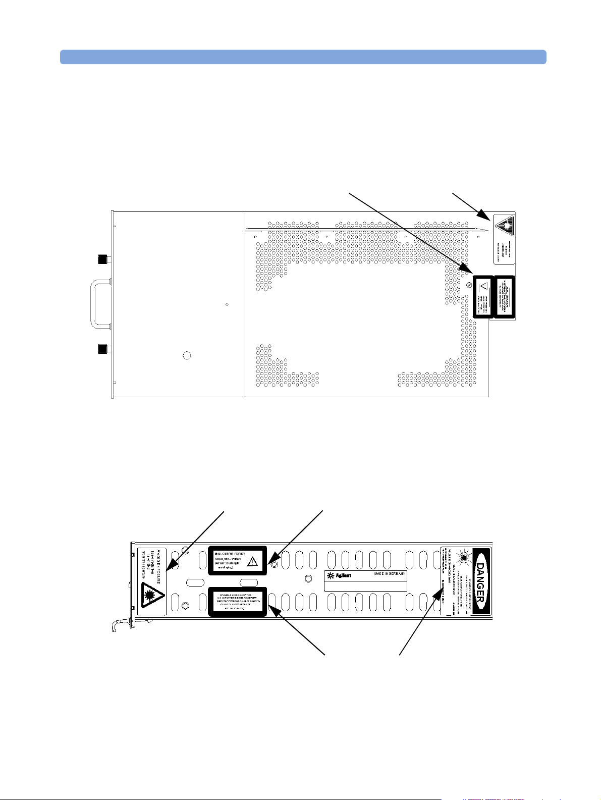
A sheet of laser safety warning labels are included with the
instrument. You MUST stick the labels in the local language onto the
outside of the instrument, in a position where they are clearly visible
to anyone using the instrument.
Top Vi e w
See page 6See page 6
Figure 3 Position of Safety Labels on Backloadable Tunable Laser Modules
These labels are applied in these positions to every Agilent 81480A,
Agilent 81680A, Agilent 81640A, Agilent 81682A, and Agilent 81642A
Tunable Laser Module before shipment.
See page 6
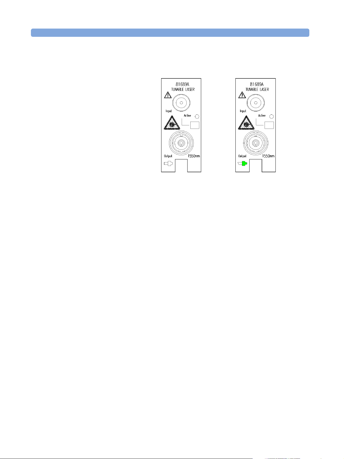
Figure 4 Position of Safety Labels on Agilent 81689A Tunable Laser Module
These labels are applied in these positions to every Agilent 81689A
Tunable Laser Module before shipment.
Agilent 81480A and 81680A, 40A, 82A, 42A, & 89A Tunable Laser Modules User’s Guide, Sixth Edition 7
See page 6
See page 6
See page 6
Page 8

Safety Summary
WARNING Please pay attention to the following laser safety warnings:
• Under no circumstances look into the end of an optical cable
attached to the optical output when the device is operational. The
laser radiation can seriously damage your eyesight.
• Do not enable the laser when there is no fiber attached to the optical
output connector.
• The laser is enabled by pressing the gray button close to the optical
output connector on the front panel of the module. The laser is on
when the green LED on the front panel of the instrument is lit.
• The use of optical instruments with this product will increase eye
hazard.
• The laser module has a built-in safety circuitry which will disable
the optical output in the case of a fault condition.
WARNING Refer Servicing only to qualified and authorized personnel.
8 Agilent 81480A and 81680A, 40A, 82A, 42A, & 89A Tunable Laser Modules User’s Guide,
Sixth Edition
Page 9

The Structure of this Manual
The Structure of this Manual
This manual is divided into two categories:
• Getting Started
This section gives an introduction to the Tunable Laser modules.
and aims to make these modules familiar to you:
– “Getting Started with Tunable Laser Sources” on page 21.
• Additional Information
This is supporting information of a non-operational nature. this
contains information concerning accessories, specifications, and
performance tests:
– “Accessories” on page 31,
– “Specifications” on page 39, and
– “Performance Tests” on page 57.
Conventions used in this manual
• Hardkeys are indicated by italics, for example, Config, or Channel.
• Softkeys are indicated by normal text enclosed in square brackets,
for example, [Zoom] or [Cancel].
• Parameters are indicated by italics enclosed by square brackets, for
example, [Range Mode], or [MinMax Mode].
• Menu items are indicated by italics enclosed in brackets, for
example, <MinMax>, or <Continuous>.
Agilent 81480A and 81680A, 40A, 82A, 42A, & 89A Tunable Laser Modules User’s Guide, Sixth Edition 9
Page 10

The Structure of this Manual
10 Agilent 81480A and 81680A, 40A, 82A, 42A, & 89A Tunable Laser Modules User’s Guide,
Sixth Edition
Page 11

Tabl e of C o nt e nts
Tab l e o f Co n t e n t s
Safety Summary 3
Safety Symbols 3
Initial Inspection 3
Line Power Requirements 4
Operating Environment 4
Input/Output Signals 4
Storage and Shipment 4
Initial Safety Information for Tunable Laser Modules 5
Laser Safety Labels 6
The Structure of this Manual 9
Conventions used in this manual 9
Getting Started with Tunable Laser Sources 21
What is a Tunable Laser ? 23
Agilent 81480A, 81680A/82A/40A/42A Tunable Laser Modules
24
Agilent 81689A Tunable Laser Module 26
Optical Output 27
Polarization Maintaining Fiber 27
Angled and Straight Contact Connectors 27
Signal Input and Output 29
Accessories 31
Modules and Options 33
Modules 34
User’s Guides 35
Options 35
Option 003 - Agilent 81682A, Agilent 81642A 35
Option 021 - Agilent 81689A 35
Option 022 - Agilent 81689A 36
Option 071 - All Tunable Laser Modules 36
Option 072 - All Tunable Laser Modules 36
Connector Interfaces and Other Accessories 36
Options 071, 021: Straight Contact Connectors 36
Agilent 81480A and 81680A, 40A, 82A, 42A, & 89A Tunable Laser Modules User’s Guide, Sixth Edition 11
Page 12

Table o f Co n ten t s
Specifications 39
Options 072, 022: Angled Contact Connectors 37
Definition of Terms 41
Absolute Wavelength Accuracy 41
Effective Linewidth 41
Linewidth 42
Minimum Output Power 42
Mode-Hop Free Tuning Range 42
Modulation Extinction Ratio 42
Modulation Frequency Range 43
Output Power 43
Output Isolation 43
Peak Power 43
Polarization Extinction Ratio 43
Power Flatness Over Modulation 44
Power Flatness Versus Wavelength 44
Power Linearity 44
Power Repeatability 44
Power Stability 45
Relative Intensity Noise (RIN) 45
Relative Wavelength Accuracy 45
Return Loss 45
Sidemode Suppression Ratio 46
Signal-to-Source Spontaneous Emission (SSE) Ratio 46
Signal-to-Total-Source Spontaneous Emission 46
Wavelength Range 47
Wavelength Repeatability 47
Wavelength Resolution 47
Wavelength Stability 47
Tunable Laser Module Specifications 48
Supplementary Performance Characteristics 54
Operating Modes 54
Internal Digital Modulation 1 54
External Digital Modulation 1 54
External Analog Modulation 1 54
External Wavelength Locking (Agilent 81680A/40A/82A/42A) 54
Coherence Control (Agilent 81680A/40A/82A/42A) 54
Continuous Sweep (Agilent 81680A/40A/82A/42A) 55
12 Agilent 81480A and 81680A, 40A, 82A, 42A, & 89A Tunable Laser Modules User’s Guide,
Sixth Edition
Page 13

Tab l e o f Co n t e n t s
Stepped Mode (Agilent 81680A/40A/82A/42A) 55
General 55
Output Isolation (typ.): 55
Return loss (typ.): 55
Polarization Maintaining Fiber (Options 071, 072): 55
Laser Class: 55
Recalibration Period: 56
Warm-up Time: 56
Environmental 56
Storage Temperature: 56
Operating Temperature: 56
Humidity: 56
Performance Tests 57
Required Test Equipment 59
Test Record 60
Test Failure 60
Instrument Specification 60
Performance Test Instructions 61
General Test Setup 61
Wavelength Tests 61
General Settings of Wavelength Meters for all Wavelength Tests 62
Wavelength Accuracy 62
Relative Wavelength Accuracy 62
Absolute Wavelength Accuracy 64
Mode Hop Free Tuning 64
Wavelength Repeatability 65
Power Tests 67
Calibration of the Agilent 81001FF Attenuation Filter 67
Maximum Output Power 69
Power Linearity 71
Power Linearity - Low Power Test 71
Example (Agilent 81680A Output 1) 73
Power Linearity - High Power Test 73
Power Linearity - Test Using Attenuation 75
Power Flatness over Wavelength 76
Power Flatness over Wavelength - Without Attenuation 76
Power Flatness over Wavelength - Using Attenuation 77
Power Stability 79
Signal-to-Source Spontaneous Emission 81
Signal-to-Source Spontaneous Emission Tests - High Power Outputs
Agilent 81480A and 81680A, 40A, 82A, 42A, & 89A Tunable Laser Modules User’s Guide, Sixth Edition 13
Page 14

Table o f Co n ten t s
81
Signal-to-Source Spontaneous Emission Tests - Low SSE Outputs 83
Signal-to-Total-Source Spontaneous Emission 88
Signal to Total SSE Tests - Low SSE Outputs 89
Optional Test 95
S i gna l t o To t al SS E Tes t s - H ig h P o we r Ou t pu ts 95
Te st Re c o r d 99
Agilent 81480A Performance Test 99
Test Equipment Used 100
Relative Wavelength Accuracy 101
Mode Hop Free Tuning 103
Wavelength Repeatability 104
Maximum Power Test 105
Power Linearity Output 1, Low SSE 106
Power Linearity Output 2, High Power Upper Power Levels 106
Power Linearity Output 2, High Power by attenuator 107
Power Flatness 108
Power Stability 109
Signal-to-Source Spontaneous Emission - 81480A Output 2, High
Power 109
Signal-to-Source Spontaneous Emission - 81480A Output 1, Low SSE
110
Signal-to-Total-Source Spontaneous Emission - 81480A Output 1, Low
SSE 111
Optional Test: Signal-to-Total-Source Spontaneous Emission - 81480A
Output 2, High Power 111
Agilent 81680A Performance Test 113
Test Equipment Used 114
Relative Wavelength Accuracy 115
Mode Hop Free Tuning 117
Wavelength Repeatability 118
Maximum Power Test 119
Power Linearity Output 1, Low SSE 120
Power Linearity Output 2, High Power Upper Power Levels 120
Power Linearity Output 2, High Power by attenuator 121
Power Flatness 122
Power Stability 123
Signal-to-Source Spontaneous Emission - 81680A Output 2, High
Power 123
Signal-to-Source Spontaneous Emission - 81680A Output 1, Low SSE
124
Signal-to-Total-Source Spontaneous Emission - 81680A Output 1, Low
SSE 125
Optional Test: Signal-to-Total-Source Spontaneous Emission - 81680A
14 Agilent 81480A and 81680A, 40A, 82A, 42A, & 89A Tunable Laser Modules User’s Guide,
Sixth Edition
Page 15

Tab l e o f Co n t e n t s
Output 2, High Power 125
Agilent 81640A Performance Test 127
Te s t E q ui pm en t Us e d 1 2 8
Relative Wavelength Accuracy 129
Relative Wavelength Accuracy Summary of all Repetitions 130
Relative Wavelength Accuracy Result 130
Absolute Wavelength Accuracy Result 130
Mode Hop Free Tuning 131
Wavelength Repeatability 132
Maximum Power Test 133
Power Linearity Output 1, Low SSE134
Power Linearity Output 2, High Power Upper Power Levels 134
Power Linearity Output 2, High Power by Attenuator 135
Power Flatness 136
Power Stability 137
Signal-to-Source Spontaneous Emission - 81640A Output 2, High
Power 137
Signal-to-Source Spontaneous Emission - 81640A Output 1, Low SSE
138
Signal-to-Total-Source Spontaneous Emission - 81640A Output 1, Low
SSE 139
Optional Test - Signal-to-Total-Source Spontaneous Emission - 81640A
Output 2, High Power 139
Agilent 81682A Performance Test 141
Te s t E q ui pm en t Us e d 1 4 2
Relative Wavelength Accuracy 143
Mode Hop Free Tuning 145
Wavelength Repeatability 146
Maximum Power Test 147
Power Linearity - 81682A 147
Power Linearity 81682A #003 Upper Power Levels 148
Power Linearity 81682A #003 by Attenuator 149
Power Flatness 150
Power Stability 151
Signal-to-Source Spontaneous Emission - 81682A 151
Optional Test: Signal-to-Total-Source Spontaneous Emission - 81682A
152
Agilent 81642A Performance Test 153
Te s t E q ui pm en t Us e d 1 5 4
Relative Wavelength Accuracy 155
Mode Hop Free Tuning 157
Wavelength Repeatability 158
Maximum Power Test 159
Power Linearity - 81642A 159
Power Linearity 81642A #003 Upper Power Levels 160
Agilent 81480A and 81680A, 40A, 82A, 42A, & 89A Tunable Laser Modules User’s Guide, Sixth Edition 15
Page 16

Table o f Co n ten t s
Cleaning Information 171
Power Linearity 81642A #003 by Attenuator 161
Power Flatness 162
Power Stability 163
Signal-to-Source Spontaneous Emission - 81642A 163
Optional Test: Signal-to-Total-Source Spontaneous Emission - 81642A
164
Agilent 81689A Performance Test 165
Tes t E qui pme nt U s ed 1 66
Relative Wavelength Accuracy 167
Wavelength Repeatability 168
Maximum Power Test 169
Power Linearity 169
Power Flatness 170
Power Stability 170
Signal-to-Source Spontaneous Emission 170
Safety Precautions 173
Why is it important to clean optical devices? 173
What do I need for proper cleaning? 174
Standard Cleaning Equipment 174
Dust and shutter caps 174
Isopropyl alcohol 175
Cotton swabs 175
Soft tissues 176
Pipe cleaner 176
Compressed air 176
Additional Cleaning Equipment 177
Microscope with a magnification range about 50X up to 300X 177
Ultrasonic bath 177
Warm water and liquid soap 178
Premoistened cleaning wipes 178
Polymer film 178
Infrared Sensor Card 178
Preserving Connectors 179
Cleaning Instrument Housings 179
Which Cleaning Procedure should I use ? 180
How to clean connectors 180
How to clean connector adapters 181
How to clean connector interfaces 182
16 Agilent 81480A and 81680A, 40A, 82A, 42A, & 89A Tunable Laser Modules User’s Guide,
Sixth Edition
Page 17

Tab l e o f Co n t e n t s
How to clean bare fiber adapters
183
How to clean lenses 184
How to clean instruments with a fixed connector interface
184
How to clean instruments with an optical glass plate 185
How to clean instruments with a physical contact interface
185
How to clean instruments with a recessed lens interface
186
How to clean optical devices which are sensitive to
mechanical stress and pressure
187
How to clean metal filters or attenuator gratings 188
Additional Cleaning Information 189
How to clean bare fiber ends 189
How to clean large area lenses and mirrors 189
Other Cleaning Hints 191
Agilent 81480A and 81680A, 40A, 82A, 42A, & 89A Tunable Laser Modules User’s Guide, Sixth Edition 17
Page 18

Table o f Co n ten t s
18 Agilent 81480A and 81680A, 40A, 82A, 42A, & 89A Tunable Laser Modules User’s Guide,
Sixth Edition
Page 19

List of Figures
Figure 1 USA Safety Labels (81480A, 81680A, 81640A, 81682A, 81642A, 81689A) . . 6
Figure 2 Non-USA Safety Labels (81480A, 81680A, 81640A, 81682A, 81642A, 81689A) 6
Figure 3 Position of Safety Labels on Backloadable Tunable Laser Modules . . . 7
Figure 4 Position of Safety Labels on Agilent 81689A Tunable Laser Module . . . 7
Figure 5 Agilent 81480A Tunable Laser Module (straight contact connectors) . . . 24
Figure 6 Agilent 81680A Tunable Laser Module (straight contact connectors) . . . 24
Figure 7 Agilent 81682A Tunable Laser Module (straight contact connector) . . . 24
Figure 8 Agilent 81640A Tunable Laser Module (straight contact connectors) . . . 24
Figure 9 Agilent 81642A Tunable Laser Module (straight contact connectors) . . . 24
Figure 10 Agilent 81689A Tunable Laser Module . . . . . . . . . . 26
Figure 11 PMF Output Connector . . . . . . . . . . . . . . 27
Figure 12 Angled and Straight Contact Connector Symbols . . . . . . . . 28
Figure 13 Agilent 81682A Tunable Laser Module (angled contact connector) . . . 28
Figure 14 Mainframes, Tunable Laser Modules, and Options . . . . . . . 33
Figure 15 Options 021, 071: Single-mode fiber/PMF with Straight Contact Connectors . 37
Figure 16 Options 022, 072: Single-mode fiber/PMF with Angled Contact Connectors . 38
Figure 17 Test Setup for Wavelength Tests . . . . . . . . . . . . 61
Figure 18 Calibration of the Agilent 81001FF Attenuation Filter, Reference Setup . . 67
Figure 19 Test Setup for Calibrating the Agilent 81001FF Attenuation Filter . . . . 68
Figure 20 Test Setup for the Maximum Output Power Tests. . . . . . . . 69
Figure 21 Test Setup for Low Power Linearity Tests. . . . . . . . . . 71
Figure 22 Test Setup for the Source Spontaneous Emission Test - High Power Outputs . 81
Figure 23 Transmission Characteristic of Fiber Bragg Grating . . . . . . . 84
Figure 24 Signal-to-Spectral SSE Measurement . . . . . . . . . . 84
Figure 25 Test Setup for Source Spontaneous Emission Test . . . . . . . 85
List of Figures
Agilent 81480A and 81680A, 40A, 82A, 42A, & 89A Tunable Laser Modules User’s Guide, Sixth Edition 19
Page 20

List of Figures
20 Agilent 81480A and 81680A, 40A, 82A, 42A, & 89A Tunable Laser Modules User’s Guide,
Sixth Edition
Page 21

Getting Started with Tunable Laser Sources
Agilent 81480A and 81680A, 40A, 82A, 42A, & 89A Tunable Laser Modules User’s Guide, Sixth Edition 21
Page 22

Getting Started with Tunable Laser Sources
This chapter describes the Agilent 81480A, Agilent 81680A,
Agilent 81640A, Agilent 81682A, Agilent 81642A, and Agilent 81689A
Tunable Laser modules.
22 Agilent 81480A and 81680A, 40A, 82A, 42A, & 89A Tunable Laser Modules User’s Guide,
Sixth Edition
Page 23

What is a Tunable Laser ? Getting Started with Tunable Laser Sources
What is a Tunable Laser ?
A Tunable Laser is a laser source for which the wavelength can be
varied through a specified range. The Agilent Technologies range of
Tunable Laser modules also allow you to set the output power, and to
choose between continuous wave or modulated power.
Agilent 81480A and 81680A, 40A, 82A, 42A, & 89A Tunable Laser Modules User’s Guide, Sixth Edition 23
Page 24
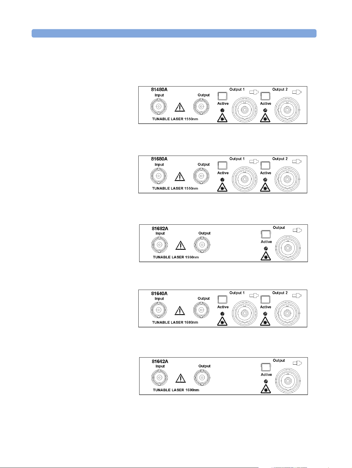
Getting Started with Tunable Laser Sources What is a Tunable Laser ?
Agilent 81480A, 81680A/82A/40A/42A
Tunable Las er Modules
Figure 5 Agilent 81480A Tunable Laser Module (straight contact connectors)
Figure 6 Agilent 81680A Tunable Laser Module (straight contact connectors)
Figure 7 Agilent 81682A Tunable Laser Module (straight contact connector)
Figure 8 Agilent 81640A Tunable Laser Module (straight contact connectors)
Figure 9 Agilent 81642A Tunable Laser Module (straight contact connectors)
24 Agilent 81480A and 81680A, 40A, 82A, 42A, & 89A Tunable Laser Modules User’s Guide,
Sixth Edition
Page 25

What is a Tunable Laser ? Getting Started with Tunable Laser Sources
The Agilent 81480A and 81680A/82A/40A/42A Tunable Laser
modules are back-loadable modules. To fit these modules into the
Agile nt 8164A mainframe see “How to Fit and Remove Modules” in th e
Agilent 8163A Lightwave Multimeter, Agilent 8164A, Lightwave
Measurement System, & Agilent 8166A Lightwave Multichannel
SystemUser’s Guide.
The Agilent 81480A and 81680A/82A/40A/42A Tunable Laser
modules have a built-in wavelength control loop to ensure high
wavelength accuracy. As these modules are all mode-hop free tunable
with continuous output power, they qualify for the test of the most
critical dense-Wavelength Division Multiplexer (dWDM) components.
The Agilent 81480A and Agilent 81640A/80A Tunable Laser modules
are equipped with two optical outputs:
• Output 1, the Low SSE output, delivers a signal with ultra-low
source spontaneous emission (SSE). It enables accurate crosstalk
measurement of DWDM components with many channels at narrow
spacing. You can characterize steep notch filt ers such as Fiber
Bragg Gratings by using this output and a power sensor module.
• Output 2, the High Power output, delivers a signal with high optical
power. You can adjust the signal by more than 60 dB by using the in-
built optical attenuator.
The Agilent 81682A/42A Tunable Laser module delivers a signal with
high optical power. If you choose O ption 0 03 , you can adjust the signal
by more than 60 dB by using the in-built optical attenuator.
Agilent 81480A and 81680A, 40A, 82A, 42A, & 89A Tunable Laser Modules User’s Guide, Sixth Edition 25
Page 26
Getting Started with Tunable Laser Sources What is a Tunable Laser ?
Agilent 81689A Tunable Laser Module
Agilent 81689A with
Straight Contact Connector
Figure 10 Agilent 81689A Tunable Laser Module
The Agilent 81689A Tunable Laser module is a front-loadable module.
To insert this module into the Agilent 8163A Lightwave Multimeter,
Agilent 8164A Lightwave Measurement System or Agilent 8166A
Lightwave Multichannel System see “How to Fit and Remove Modu les”
in the Agilent 8163A Lightwave Multimeter, Agilent 8164A Lightwave
Measurement System, & Agilent 8166A Lightwave Multichannel
System User’s Guide.
You can use the Agilent 81689A Tunable Laser module to set up a
realistic multi-channel test-bed for DWDM transmission systems. Its
continuous, mode-hop free tuning makes it quick and easy to set even
the most complex configurations to the target wavelengths and power
levels.
The Agilent 8163A Lightwave Multimeter, a Power Sensor module,and
a Agilent 81689A Tunable Laser module together represent a smart
loss-test set with selectable wavelength.
Agilent 81689A with
Angled Contact Connector
26 Agilent 81480A and 81680A, 40A, 82A, 42A, & 89A Tunable Laser Modules User’s Guide,
Sixth Edition
Page 27
Optical Output Getting Started with Tunable Laser Sources
Optical Output
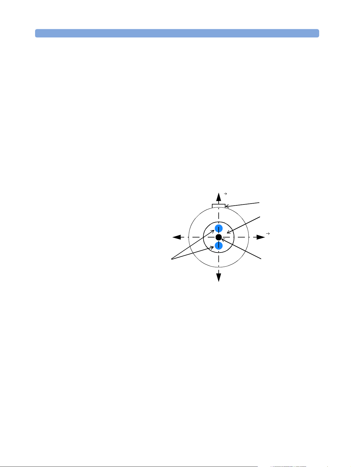
Polarization Maintaining Fiber
If you have an instrument with a polarization maintaining fiber (PMF),
the PMF is aligned to maintain the state of polarization.
The fiber is of Panda type, with TE mode in the slow axis in line with
the connector key. A well defined state of polarization ensures
constant measurement conditions.
The Agilent 81480A and 81680A/40A/82A/42A Tunable Laser
modules are equipped with PMF outputs as standard.
For the Agilent 81689A Tunable Laser module, PMF output is available
as an option.
Stress Rods
Figure 11 PMF Output Connector
Angled and Straight Contact Connectors
Angled contact connectors help you to control return lo ss. With angled
fiber endfaces, reflected light tends to reflect into the cladding,
reducing the amount of light that reflects back to the source.
E
Connector Key
Fiber Cladding
H
Fiber Core
(8-µm Diameter)
Slow Axis (Polarization Axis)
Not to Scale
The Agilent 81480 and 81680A/40A/82A/42A/89A Tunable Laser
modules can have the following connector interface options:
• Option 071, Polarization-maintaining fiber straight contact
connectors, or
• Option 072, Polarization-maintaining fiber angled contact
connectors.
Agilent 81480A and 81680A, 40A, 82A, 42A, & 89A Tunable Laser Modules User’s Guide, Sixth Edition 27
Page 28
Getting Started with Tunable Laser Sources Optical Output
Two additional connector interface options are available for the
Agilent 81689A Tunable Laser module:
• Option 021, Standard single-mode fiber straight contact connectors,
or
• Option 022, Standard single-mode fiber angled contact connectors.
CAUTION If the contact connector on your instrument is angled, you can only
use cables with angled connectors with the instrument.
Angled Contact
Connector Symbol
Figure 12 Angled and Straight Contact Connector Symbols
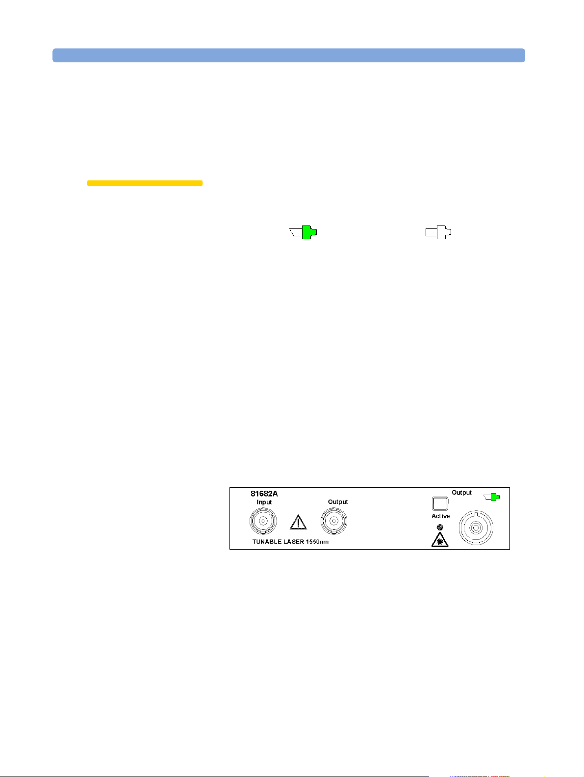
Figure 12 shows the symbols that tell you whether the contact
connector of your Tunable Laser module is angled or straight. The
angled contact connector symbol is colored green.
Figure 7 and Figure 13 show the front panel of the Agilent 81682A
Tunable Laser module with straight and angled contact connectors
respectively.
You should connect straight contact fiber end connectors with neutral
sleeves to straight contact connectors and connect angled contact fiber
end connectors with green sleeves to angled contact connectors.
NOTE You cannot connect angled non-contact fiber end connectors with
orange sleeves directly to the instrument.
Straight Contact
Connector Symbol
Figure 13 Agilent 81682A Tunable Laser Module (angled contact connector)
See “Accessories” on page 31 for further details on connector
interfaces and accessories.
28 Agilent 81480A and 81680A, 40A, 82A, 42A, & 89A Tunable Laser Modules User’s Guide,
Sixth Edition
Page 29

Signal Input and Output Getting Started with Tunable Laser Sources
Signal Input and Output
CAUTION There are two BNC connectors on the front panel of the
Agilent 81480A, Agilent 81680A, Agilent 81680A, Agilent 81640A,
Agilent 81682A, and Agilent 81642A - a BNC input connector and a
BNC output connector.
There is one BNC connector on the front panel of the Agilent 81689A a BNC input connector.
An absolute maximum of ±6 V can be applied as an external voltage to
any BNC connector.
Agilent 81480A and 81680A, 40A, 82A, 42A, & 89A Tunable Laser Modules User’s Guide, Sixth Edition 29
Page 30

Getting Started with Tunable Laser Sources Signal Input and Output
30 Agilent 81480A and 81680A, 40A, 82A, 42A, & 89A Tunable Laser Modules User’s Guide,
Sixth Edition
Page 31

Accessories
Agilent 81480A and 81680A, 40A, 82A, 42A, & 89A Tunable Laser Modules User’s Guide, Sixth Edition 31
Page 32

Accessories
The Agilent 81480A and 81680A/40A/82A/42A/89A Tunable Laser
Source Modules are available in various configurations for the best
possible match to the most common applications.
This chapter provides information on the available options and
accessories.
32 Agilent 81480A and 81680A, 40A, 82A, 42A, & 89A Tunable Laser Modules User’s Guide,
Sixth Edition
Page 33

Modules and Options Accessories
Modules and Options
Figure 14 shows all the options that are available for all Tunable Laser
modules and the instruments that support these modules.
Agilent 8164A
Lightwave Measurement System
Agilent 81480A
Tuna ble Laser
1400 nm
Low SSE
Agilent 81680A
Tuna ble Laser
1550 nm
Low SSE
Option 071
PMF,
Panda-type,
Straight
Contact
Option 072
PMF,
Panda-type,
Angled
Contact
Agilent 81640A
Tuna ble La se r
1600 nm
Low SSE
Agilent 81682A
Tunable Laser
1550 nm
+ 8 dBm
Option 003
Attenuator
Agilent 81645A
Filler Module
Agilent 81642A
Tunable Laser
1600 nm
+ 7 dBm
Option 021
Single-mode
fiber,
Straight
Contact
Agilent 81689A
Compact
Tuna ble Laser
1550 nm
Option 022
Single-mode
fiber,
Angled
Contact
Agilent 8163A
Lightwave Multimeter
Agilent 8163A
Lightwave
Multimeter
Modules
Option 071
PMF,
Panda-type,
Straight
Contact
Option 072
PMF,
Panda-type,
Angled
Contact
HP 8153A
Lightwave
Multimeter
Modules
Figure 14 Mainframes, Tunable Laser Modules, and Options
Agilent 81480A and 81680A, 40A, 82A, 42A, & 89A Tunable Laser Modules User’s Guide, Sixth Edition 33
Page 34

Accessories Modules
Modules
The Agilent 8164A Lightwave Measurement System supports the
Agilent 81480A and 81680A/40A/82A/42A/89A Tunable Laser
modules. In addition, the Agilent 8163A Lightwave Multimeter
supports the Agilent 81689A Tunable Laser module.
Tunable Laser Modules
Model No. Description
Agilent 81480A Tunable Laser for the Test of Critical dense-WDM Components
Agilent 81680A Tunable Laser for the Test of Critical dense-WDM Components
Agilent 81640A Tunable Laser for the Test of Critical Components in both
dense-WDM Bands, the C and L bands
Agilent 81682A Tunable Laser for the Test of Optical Amplifiers and Passive
Components
Agilent 81642A Tunable Laser for the Test of Optical Amplifiers and Passive
Components in both dense-WDM Bands.
Agilent 81689A Tunable Laser for Multi-Channel Test Applications
Filler Module
Filler Module
Model No. Description
Agilent 81645A Filler Module
The Agilent 81645A Filler Module is required to operate the
Agile nt 8164A mainframe if it is used without a back-loadable Tunable
Laser module. It can be used to:
• prevent dust pollution and
• optimize cooling by guiding the air flow.
See the "Installation and Maintenance" chapter of the Agilent 81480A,
Agilent 81680A, Agilent 81682A, Agilent 81640A, & Agilent 81689A
Tunable Laser Modules User’s Guide for more details on installing the
Agilent 81645A Filler Module.
34 Agilent 81480A and 81680A, 40A, 82A, 42A, & 89A Tunable Laser Modules User’s Guide,
Sixth Edition
Page 35

Modules Accessories
User’s Guides
User’s Guides
Opt Description Part No.
Agilent 81480A, Agilent 81680A, Agilent 81682A, Agilent 81640A, &
Agilent 81689A Tunable Laser Modules User’s Guide
ABJ Japanese Agilent 81480A, Agilent 81680A, Agilent 81682A,
Agilent 81640A, & Agilent 81689A Tunable Laser Modules User’s
Guide
ABF French Agilent 81480A, Agilent 81680A, Agilent 81682A,
Agilent 81640A, & Agilent 81689A Tunable Laser Modules User’s
Guide
AB0 Traditional Chinese (Taiwan) Agilent 81480A, Agilent 81680A,
Agilent 81682A, Agilent 81640A, & Agilent 81689A Tunable Laser
Modules
User’s Guide
AB1 Korean Agilent 81480A, Agilent 81680A, Agilent 81682A,
Agilent 81640A, & Agilent 81689A Tunable Laser Modules User’s
Guide
8164A 0B2 Agilent 8163A Lightwave Multimeter, Agilent 8164A Lightwave
Measurement System, & Agilent 8166A Lightwave Multichannel
System Programming Guide
8164A 0BF Agilent 8163A Lightwave Multimeter, Agilent 8164A Lightwave
Measurement System, & Agilent 8166A Lightwave Multichannel
System User’s Guide
81680-90014
81680-91514
81680-91214
81680-91714
81680-91814
08164-91016
08164-91011
Options
Option 003 - Agilent 81682A, Agilent 81642A
Built-in optical attenuator with 60 dB attenuation range.
NOTE The Agilent 81640A/80A Tunable Laser Modules have a built-in optical
attenuator as standard for Output 2, the High Power output.
A built-in optical attenuator is not available for the Agilent 81689A.
Option 021 - Agilent 81689A
Standard single-mode fiber, for straight contact connectors.
Agilent 81480A and 81680A, 40A, 82A, 42A, & 89A Tunable Laser Modules User’s Guide, Sixth Edition 35
Page 36

Accessories Connector Interfaces and Other Accessories
Option 022 - Agilent 81689A
Standard single-mode fiber, for angled contact connectors.
Option 071 - All Tunable Laser Modules
Polarization-maintaining fiber, Panda-type, for straight contact
connectors.
Option 072 - All Tunable Laser Modules
Polarization-maintaining fiber, Panda-type, for angled contact
connectors.
Connector Interfaces and Other Accessories
The Agilent 81480A and 81680A/40A/82A/42A/89A Tunable Laser
modules are supplied with one of two connector interface options:
• Option 071, Polarization-maintaining fiber straight contact
connectors, or
• Option 072, Polarization-maintaining fiber angled contact
connectors.
Two additional connector interface options are available for the
Agilent 81689A Tunable Laser module:
• Option 021, Standard single-mode fiber straight contact connectors,
or
• Option 022, Standard single-mode fiber angled contact connectors.
Options 071, 021: Straight Contact Connectors
If you want to use straight connectors (such as FC/PC, Diamond HMS10, DIN, Biconic, SC, ST or D4) to connect to the instrument, you must
do the following:
36 Agilent 81480A and 81680A, 40A, 82A, 42A, & 89A Tunable Laser Modules User’s Guide,
Sixth Edition
Page 37

Connector Interfaces and Other Accessories Accessories
1 Attach your connector interface to the interface adapter.
See Table 2 for a list of the available connector interfaces.
2 Connect your cable (see Figure 15).
Agilent 810
00AI
Connector
Interface
Diamond
HMS-10
Agilent 810
00FI
Connector
Interface
FC/PC/SPC
Agilent 810
00GI
Connector
Interface
D4
Agilent 810
00HI
Connector
Interface
Diamond
E-2000
Agilent 810
00KI
Connector
Interface
SC
Agilent 810
00SI
Connector
Interface
DIN 47256
Agilent 810
00VI
Connector
Interface
ST
Agilent 8100
Connector
Interface
Biconic
Figure 15 Options 021, 071: Single-mode fiber/PMF with Straight Contact Connectors
Table 2 Straight Contact Connector Interfaces
Description Model No.
Biconic Agilent 81000 WI
D4 Agilent 81000 GI
Diamond HMS-10 Agilent 81000 AI
DIN 47256 Agilent 81000 SI
FC / PC / SPC Agilent 81000 FI
SC Agilent 81000 KI
ST Agilent 81000 VI
Diamond E-2000 Agilent 81000 HI
Options 072, 022: Angled Contact
0WI
Connectors
If you want to use angled connectors (such as FC/APC, Diamond HRL10, or SC/APC) to connect to the instrument, you must do the
following:
1 Attach your connector interface to the interface adapter.
See Table 3 for a list of the available connector interfaces.
Agilent 81480A and 81680A, 40A, 82A, 42A, & 89A Tunable Laser Modules User’s Guide, Sixth Edition 37
Page 38

Accessories Connector Interfaces and Other Accessories
2 Connect your cable (see Figure 16).
Agilent 8100
0NI
Connector
Interface
FC/APC
Agilent 8100
0KI
Connector
Interface
SC/APC
Agilent 8100
0HI
Connector
Interface
Diamond
E-2108.6
Agilent 8100
0SI
Connector
Interface DIN
47256/4108.6
Figure 16 Options 022, 072: Single-mode fiber/PMF with Angled Contact Connectors
Table 3 Angled Contact Connector Interfaces
Description Model No.
DIN 47256-4108.6 Agilent 81000 SI
FC / APC Agilent 81000 NI
SC / APC Agilent 81000 KI
Diamond E-2108.6 Agilent 81000 HI
38 Agilent 81480A and 81680A, 40A, 82A, 42A, & 89A Tunable Laser Modules User’s Guide,
Sixth Edition
Page 39

Specifications
Agilent 81480A and 81680A, 40A, 82A, 42A, & 89A Tunable Laser Modules User’s Guide, Sixth Edition 39
Page 40

Specifications
The Agilent 81480A, Agilent 81680A, Agilent 81640A, Agilent 81682A,
Agilent 81642A and Agilent 81689A Tunable Laser modules are
produced to the ISO 9001 international quality system standard as
part of Agilent Technologies’ commitment to continually increasing
customer satisfaction through improved quality control.
Specifications describe the modules’ warranted performance.
Supplementary performance characteristics describe the modules
non-warranted typical performance.
Because of the modular nature of the instrument, these performance
specifications apply to these modules rather than the mainframe unit.
40 Agilent 81480A and 81680A, 40A, 82A, 42A, & 89A Tunable Laser Modules User’s Guide,
Sixth Edition
Page 41

Definition of Terms Specifications
Definition of Terms
This section defines terms that are used both in this chapter and
“Performance Tests” on page 57.
Generally, all specifications apply for the given environmental
conditions and after warmup time.
Measurement principles are indicated. Alternative measurement
principles of equal value are also acceptable.
Absolute Wavelength Accuracy
The maximum difference between the actual wavelength and the
displayed wavelength of the TLS. Wavelength is defined as wavelength
in vacuum.
Conditions: constant power level, temperature within operating
temperature range, coherence control off, measured at high power
output.
Validity: within given time span after wavelength zeroing, at a given
maximum temperature difference between calibration and
measurement.
Measurement with wavelength meter. Averaging time given by
wavelength meter, ≥1 s.
NOTE The abso lute wavelength accuracy of Output 1, the Lo w SSE Ou tput, of
the Agilent 81680A/40A Tunable Laser modules is the same as the
absolute wavelength accuracy of Output 2, the High Power Output
(guaranteed by design).
Effective Linewidth
The time-averaged 3-dB width of the optical spectrum, expressed in
Hertz.
Conditions: temperature within operating temperature range,
coherence control on, power set to specified value.
Agilent 81480A and 81680A, 40A, 82A, 42A, & 89A Tunable Laser Modules User’s Guide, Sixth Edition 41
Page 42

Specifications Definition of Terms
Measurement with heterodyning technique: the output of the laser
under test is mixed with another laser of the same type on a wide
bandwidth photodetector. The electrical noise spectrum of the
photodetector current is measured with an Agilent Lightwave Signal
Analyzer, and the linewidth is calculated from the heterodyne
spectrum (Lightwave signal analyzer settings: resolution bandwidth
1 MHz; video bandwidth 10 kHz; sweep time 20 ms; single scan).
Linewidth
The 3-dB width of the optical spectrum, expressed in Hertz.
Conditions: temperature within operating temperature range,
coherence control off, power set to maximum flat power (maximum
attainable power within given wavelength range).
Measurement with self-heterodyning technique: the output of the
laser under test is sent through a Mach-Zehnder interferometer in
which the length difference of the two arms is longer than the
coherence length of the laser. The electrical noise spectrum of the
photodetector current is measured with an Agilent Lightwave Signal
Analyzer, and the linewidth is calculated from the heterodyne
spectrum (Lightwave signal analyzer settings: resolution bandwidth 1
MHz; video bandwidth 10 kHz; sweep time 20 ms; single scan).
Minimum Output Power
The minimum output power for which the specifications apply.
Mode-Hop Free Tuning Range
The tuning range for which no abrupt wavelength change occurs
during fine wavelength stepping. Abrupt change is defined as change
of more than 25 pm.
Conditions: within specified wavelength range, at specified
temperature range and output power. Tuning from outside into the
mode-hop free tuning range is not allowed.
Modulation Extinction Ratio
The ratio of total power in on-state to total power in off-state,
expressed in dB.
Conditions: Internal or external modulation, tunable laser at highest
power setting.
42 Agilent 81480A and 81680A, 40A, 82A, 42A, & 89A Tunable Laser Modules User’s Guide,
Sixth Edition
Page 43

Definition of Terms Specifications
Measurement with optical spectrum analyzer. Tunable laser switched
on and off.
Modulation Frequency Range
The range of frequencies for which the modulation index is above − 3
dB of the highest modulation index. In this context, modulation index
is defined as the AC power amplitude (peak-to-peak) divided by the
average power.
Output Power
The achievable output power for the specified TLS tuning range.
Conditions: temperature within operating temperature range.
Measurement with power meter at the end of a single-mode fiber
patchcord.
Output Isolation
The insertion loss of the built-in isolator in the backward direction.
Measurement: Cannot be measured from the outside. This
characteristic is based on known isolator characteristics.
Peak Power
The highest optical power within specified wavelength range.
Polarization Extinction Ratio
The ratio of optical power in the slow axis of the polarizationmaintaining fiber to optical power in the fast axis within a specified
wavelength range.
Conditions: only applicable for TLS with polarization maintaining
fiber with the TE mode in slow axis and oriented in line with
connector key, at constant power level.
Measurement with a polarization analyzer at the end of a polarizationmaintaining patchcord, by sweeping the wavelength, thereby creating
circular traces on the Poincaré sphere, then calculating the
polarization extinction ratio from the circle diameters.
Agilent 81480A and 81680A, 40A, 82A, 42A, & 89A Tunable Laser Modules User’s Guide, Sixth Edition 43
Page 44

Specifications Definition of Terms
Power Flatness Over Modulation
When changing the wavelength and modulation frequency, and
measuring the differences between actual and displayed power levels
(in dB), the power flatness is ± half the span between the maximum
and the minimum value of all differences.
Conditions: uninterrupted line voltage, constant power setting,
temperature within ±2 K, external modulation ON.
Measurement with optical power meter.
Power Flatness Versus Wavelength
When changing the wavelength at constant power setting and
recording the differences between actual and displayed power levels,
the power flatness is ± half the span (in dB) between the maximum
and the minimum of the measured power levels.
Conditions: uninterrupted TLS output power, constant power setting,
temperature within ±1K.
Measurement with optical power meter.
Power Linearity
When changing the power level and measuring the differences (in dB)
between actual and displayed power levels, the power linearity is ±
half the span (in dB) between the maximum and the minimum value of
all differences.
Conditions: power levels from within specified output power range,
uninterrupted TLS output power, at fixed wavelength settings and
stable temperature.
Measurement with optical power meter.
Power Repeatability
The random uncertainty in reproducing the power level after changing
and re-setting the power level. The power repeatability is ± half the
span (in dB) between the highest and lowest actual power.
Conditions: uninterrupted TLS output power, constant wavelength,
temperature within ±1 K, short time span.
Measurement with optical power meter.
NOTE The long-term power repeatability can be obtained by taken the power
repeatability and power stability into account.
44 Agilent 81480A and 81680A, 40A, 82A, 42A, & 89A Tunable Laser Modules User’s Guide,
Sixth Edition
Page 45

Definition of Terms Specifications
Power Stability
The change of the power level during given time span, expressed as ±
half the span (in dB) between the highest and lowest actual power.
Conditions: uninterrupted TLS output power, constant wavelength
and power level settings, temperature within ±1 K, time span as
specified.
Measurement with optical power meter.
Relative Intensity Noise (RIN)
The square of the (spectrally resolved) RMS optical power amplitude
divided by the measurement bandwidth and the square of the average
optical power, expressed in dB/Hz.
Conditions: at specified output power, coherence control off,
temperature within operating temperature range, frequency range 0.1
to 6 GHz.
Measurement with Agilent Lightwave Signal Analyzer.
Relative Wavelength Accuracy
When randomly changing the wavelength and measuring the
differences between the actual and displayed wavelengths, the relative
wavelength accuracy is ± half the span between the maximum and the
minimum value of all differences.
Conditions: uninterrupted TLS output power, constant power level,
temperature within operating temperature range, observation time 10
minutes maximum (constant temperature), coherence control off,
measured at high power output.
Measurement with wavelength meter. Averaging time given by
wavelength meter, ≥1 s.
NOTE The relative wavelength accuracy of Output 1, the Low SSE Output, of
the Agilent 81640A/80A Tunable Laser modules is the same as the
relative wavelength accuracy of Output 2, the High Power Output
(guaranteed by design).
Return Loss
The ratio of optical power incident to the TLS outpu t port, at the TLS's
own wavelength, to the power reflected from the TLS output port.
Conditions: TLS disabled.
Agilent 81480A and 81680A, 40A, 82A, 42A, & 89A Tunable Laser Modules User’s Guide, Sixth Edition 45
Page 46

Specifications Definition of Terms
Sidemode Suppression Ratio
The ratio of average signal power to the optical power of the highest
sidemode within a distance from 0.1 to 6 GHz to the signal's optical
frequency, expressed in dB.
Conditions: at a specified output power and wavelength range,
temperature within operating temperature range, coherence control
off.
Measurement with the Agilent Lightwave Signal Analyzer, by
analyzing the heterodyning between the main signal and the highest
sidemode.
Signal-to-Source Spontaneous Emission (SSE) Ratio
The ratio of signal power to maximum spontaneous e mission power in
1 nanometer bandwidth within a ±3 nm window around the signal
wavelength, where ±1 nm around the signal wavelength are excluded,
at the specified output power, expressed in dB/nm.
Conditions: output power set to specified values, at temperatures
within operating temperature range, coherence control off.
Measurement with optical spectrum analyzer (OSA) at 0.5 nm
resolution bandwidth (to address the possibility of higher SSE within
a narrower bandwidth), then extrapolated to 1 nm bandwidth. On
low-SSE output (if applicable), with fiber Bragg grating inserted
between the TLS and the OSA in order to suppress the signal, thereby
enhancing the dynamic range of the OSA.
NOTE The specified signal-to-SSE ratio is also applicable to output powers
higher than the specified values.
Signal-to-Total-Source Spontaneous Emission
The ratio of signal power to total spontaneous emission power, at the
specified achievable output power, expressed in dB.
Conditions: output power set to specified values, at temperatures
within operating temperature range, coherence control off.
Measurement with optical spectrum analyzer, by integrating the
source spontaneous emission and excluding the remnant signal. On
low-SSE output (if applicable), with fiber Bragg grating inserted
between the TLS and the OSA in order to suppress the signal, thereby
enhancing the dynamic range of the OSA.
46 Agilent 81480A and 81680A, 40A, 82A, 42A, & 89A Tunable Laser Modules User’s Guide,
Sixth Edition
Page 47

Definition of Terms Specifications
NOTE The specified signal-to-total-SSE ratio is also applicable to output
powers higher than the specified values.
Wavelength Range
The range of wavelengths for which the specifications apply.
Wavelength Repeatability
The random uncertainty in reproducing a wavelength after detuning
and re-setting the wavelength. The wavelength repeatability is ± half
the span between the maximum and the minimum value of all actual
values of this wavelengths.
Conditions: uninterrupted TLS output power, constant power level,
temperature within operating temperature range, coherence control
off, short time span.
Measurement wit h w a veleng th m eter a t high power o u t put. Ave r a ging
time given by wavelength meter, ≥1 s.
NOTE The wavelength repeatability of Output 1, the Low SSE Output, of the
Agile nt 81680A/40A Tunable Laser modules is the same as th e relative
wavelength accuracy of Output 2, the High Power Output (guaranteed
by design).
NOTE The long-term wavelength repeatability can be obtained by taken the
wavelength repeatability and wavelength stability into account.
Wavelength Resolution
The smallest possible displayed wavelength increment/decrement.
Wavelength Stability
The change of wavelength during given time span, expressed as ± half
the span between the maximum and the minimum of all actual
wavelengths.
Conditions: uninterrupted TLS output power, constant wavelength
and power level settings, coherence control off, temperature within ±1
K, time span as specified.
Measurement with wavelength meter. Averaging time given by
wavelength meter, ≥1 s.
Agilent 81480A and 81680A, 40A, 82A, 42A, & 89A Tunable Laser Modules User’s Guide, Sixth Edition 47
Page 48

Specifications Tunable Laser Module Specifications
Tunable Laser Module Specifications
Agilent 81480A
Agilent 81480A
Output 1
(Low SSE)
Wavelength range 1370 nm to 1480 nm
Wavelength resolution 0.1 pm, 15 MHz at 1450 nm
Mode-hop free tuning range
Absolute wavelength accuracy
Relative wavelength accuracy
Wavelength repeatability
Wavelength stability (typ., 24 hours at
constant temperature)
Tuning speed (typ. for a 1/10/100 nm step) 400 ms/ 600 ms/ 2.8 s
Linewidth (typ.), coherence control off 100 kHz
Effective linewidth (typ.), coherence ctrl. on> 50 MHz (1420 - 1470 nm), at maximum flat output power)
Output power
(continuous power during tuning)
3
9
1, 2, 9
1, 2, 9
2, 9
2, 9
full wavelength range
±0.01 nm
±5 pm, typ. ±2 pm
±1 pm, typ. ±0.5 pm
< ±1 pm
> -4.5 dBm peak typ
> -7 dBm (1420 – 1470 nm)
> +5.5 dBm peak typ
> +3 dBm (1420 - 1470 nm)
Agilent 81480A
Output 2
(High Power)
Minimum output power
Power stability
Power repeatability (typ.)
Power linearity
3
3
3
3, 9
> -13 dBm (1370 – 1480 nm)[9]
-13 dBm -3 dBm
±0.01 dB, 1 hour (1420nm-1480nm)
typ. ±0.01 dB, 1 hour (1370nm-1420nm) [9]
typ. ±0.03 dB, 24 hours
±0.01 dB
±0.1 dB (1420nm-1480nm)
typ. ±0.1dB (1370nm-1420nm) [9]
> -3 dBm (1370 - 1480 nm)[9]
(-60 dBm in attenuation mode)
±0.3 dB (1420nm-1480nm)
typ. ±0.3 dB (1370nm-1420nm) [9]
48 Agilent 81480A and 81680A, 40A, 82A, 42A, & 89A Tunable Laser Modules User’s Guide,
Sixth Edition
Page 49

Tunable Laser Module Specifications Specifications
Power flatness versus wavelength
Side-mode suppression ratio (typ.)
Signal-to-Source Spontaneous Emission
5, 8
Ratio
Signal-to-Total-Source Spontaneous
Emission ratio
6, 8
3, 9
4, 8, 9
±0.2 dB, typ. ±0.1 dB
(1420-1480nm)
±0.2 dB typ (1370nm-1420nm)
> 40 dBc (1380 - 1480 nm)
> 61 dB/nm [7]
(1420 – 1470 nm)
> 55 dB/nm [7] [9]
(typ., 1370 – 1480 nm)
> 58 dB
(1420 – 1470 nm) [7]
±0.3 dB, typ. ±0.2 dB
(1420nm-1480nm)
±0.3 dB typ (1370nm-1420nm)
> 40 dB/ nm
(1420 – 1470 nm)
> 35 dB/ nm
(1370 – 1480 nm)
> 28 dB
(typ., 1420 - 1470 nm )
> 53 dB
(typ., 1370 - 1480 nm) [7] [9]
Relative intensity noise (RIN, typ.)
8
-145 dB/Hz (1420 - 1470 nm)
1. Valid for one month and within a ±5 K temperature range after automatic wavelength zeroing.
2. At CW operation. Measured with wavelength meter based on wavelength in vacuum.
3. Applies to the selected output.
4. Measured by heterodyning method.
5. Measured with optical spectrum analyzer at 1 nm resolution bandwidth.
6. Measured with optical spectrum analyzer.
7. Measured with fiber Bragg grating to suppress the signal.
8. Output power as specified per wavelength range and output port.
9. Wavelength must not be equal to any water absorption line
Agilent 81480A and 81680A, 40A, 82A, 42A, & 89A Tunable Laser Modules User’s Guide, Sixth Edition 49
Page 50

Specifications Tunable Laser Module Specifications
Agilent 81680A and Agilent 81640A
Agilent 81680A
Output 1
(Low SSE)
Agilent 81680A
Output 2
(High Power)
Agilent 81640A
Output 1
(Low SSE)
Agilent 81640A
Output 2
(High Power)
Wavelength range 1460 nm to 1580 nm 1510 nm to 1640 nm
Wavelength resolution 0.1 pm, 12.5 MHz at 1550 nm
Mode hop free tuning range 1460 nm to 1580 nm 1510 nm to 1640 nm
Absolute
wavelength accuracy
Relative wavelength accuracy
Wavelength repeatability
Wavelength stability (typ., 24 hours
at constant temperature)
Tuning speed
1, 2
1, 2
2
2
± 0.01 nm ± 0.015 nm
± 5pm, typ. ± 2pm ± 7pm, typ. ± 3pm
± 1 pm, typ. ± 0.5 pm
≤± 1 pm
400 ms/600 ms/2.8 s
(typ. for a 1/10/100 nm step)
Linewidth (typ.), coherence control
100 kHz
off.
Effective Linewidth (typ.), coherence
control on
Output power
3
>50 MHz (1480 to 1580 nm, at maximum
flat output power)
≥ −4 dBm peak typ.
≥ 6 dBm peak typ.
>50 MHz (1520 to 1620 nm, at maximum
flat output power)
≥ −5 dBm peak typ.
≥ 4 dBm peak typ.
(continuous power during tuning)
Minimum output power
Power stability
3
Power repeatability (typ.)
Power linearity
3
3
3
Power flatness versus wavelength
Side-mode Suppression ratio (typ.)
4,8
(1520-1570 nm)
(1480-1580 nm)
(1460-1580 nm)
3
≥ −6 dBm
≥ −10 dBm
≥ −13 dBm
−13 dBm −3 dBm
± 0.1 dB ± 0.3 dB ± 0.1 dB ± 0.3 dB
± 0.2 dB,
typ.
± 0.1 dB
≥ 40 dBc
(1480-1580 nm)
≥ 5 dBm
(1520-1570 nm)
≥ 1 dBm
(1480-1580 nm)
≥ −3 dBm
(1460-1580 nm)
(−60 dBm in atten-
uation mode)
± 0.01 dB, 1 hour.
typ.
± 0.03 dB, 24 hours
± 0.01 dB
± 0.3 dB,
typ.
± 0.15 dB
≥ −7 dBm
(1530-1610 nm)
(1530-1610 nm)
≥ −9 dBm
(1520-1620 nm)
(1520-1620 nm)
≥ −13 dBm
(1510-1640 nm)
(1510-1640 nm)
−13 dBm −5 dBm
(−60 dBm in atten-
uation mode)
± 0.2 dB,
typ.
± 0.1 dB
typ.
≥ 40 dBc
(1530-1610 nm)
≥ 2 dBm
≥ 0 dBm
≥ −5 dBm
± 0.3 dB,
± 0.15 dB
50 Agilent 81480A and 81680A, 40A, 82A, 42A, & 89A Tunable Laser Modules User’s Guide,
Sixth Edition
Page 51

Tunable Laser Module Specifications Specifications
Signal-to-Source Spontaneous Emission Ratio
Signal-to-Total-Source Spontaneous
Emission
Relative Intensity noise (RIN, typ.)
1. Valid for one month and within a
5,8
Ratio
6,8
8
±5 K temperature range after wavelength zeroing.
Agilent 81680A
Output 1
(Low SSE)
≥ 63 dB/nm
(1520-1570 nm)
≥ 58 dB/nm
1480-1580 nm)
≥ 53 dB/nm
7
(typ.,
7
(typ.,
1460-1580 nm)
7
≥ 60 dB
(1520-1570 nm)
(typ., 1480-1580 nm)
≥ 50 dB
7
− 145 dB/Hz (1480-1580 nm) − 145 dB/Hz (1530-1610 nm)
7
Agilent 81680A
Output 2
(High Power)
≥ 45 dB/nm
(1520-1570 nm)
≥ 40 dB/nm
(1480-1580 nm)
≥ 35 dB/nm
(1460-1580 nm)
≥ 30 dB
(typ., 1520-1570
nm)
Agilent 81640A
≥ 60 dB/nm
(1530-1610 nm)
≥ 55 dB/nm
1520-1620 nm)
≥ 50 dB/nm
(typ., 1510-1640 nm)
(1530-1610 nm)
(typ., 1510-1640 nm)
2. At CW operation. Measured with wavelength meter based on wavelength in vacuum.
3. Applies to the selected output.
4. Measured by heterodyning method.
5. Measured with optical spectrum analyzer at 1 nm resolution bandwidth.
6. Measured with optical spectrum analyzer.
Output 1
(Low SSE)
7
7
≥ 55 dB
7
≥ 45 dB
7
(typ.,
7
Agilent 81640A
Output 2
(High Power)
≥ 45 dB/nm
(1530-1610 nm)
≥ 40 dB/nm
(1520-1620 nm)
≥ 35 dB/nm
(1510-1640 nm)
≥ 27 dB
(typ., 1530-1610
nm)
7. Measured with Fiber Bragg Grating to supress the signal.
8. Output power as specified per wavelength range and ouput port.
9. Warm up time: 1 hour
Agilent 81480A and 81680A, 40A, 82A, 42A, & 89A Tunable Laser Modules User’s Guide, Sixth Edition 51
Page 52

Specifications Tunable Laser Module Specifications
Agilent 81682A, Agilent 81642A
and Agilent 81689A
Agilent 81682A Agilent 81642A Agilent 81689A
Wavelength range 1460 nm to 1580 nm 1510 nm to 1640 nm 1525 nm to 1575 nm
Wavelength resolution 0.1 pm, 12.5 MHz at
1550 nm
0.1 pm, 12.5 MHz at
1550 nm
Mode hop-free tuning range 1460 nm to 1580 nm full wavelength range
Absolute wavelength accuracy
± 0.01 nm
1, 2
Relative wavelength accuracy ± 5pm, typ. ± 2pm
Wavelength repeatability
Wavelength stability (typ, over 24 hours
± 1pm, typ. ± 0.5 pm
< ± 1pm
2
1, 2
± 0.015 nm
± 7pm, typ. ± 3pm
2
± 1pm, typ. ± 0.5 pm
< ± 1pm
1, 2
1, 2
2
at constant temperature)
Tuning speed 400 ms/600 ms/2.8 s
(typ. for a 1/10/100 nm
step)
Linewidth (typ.) 100 kHz,
coherence control off
Effective Linewidth (typ.), coherence
control on
> 50 MHz (1480 -
1580 nm, at maximum flat
output power)
Output power
(continuous power during tuning)
≥ 8dBm peak typ.
≥ 6 dBm (1520 - 1570 nm)
≥ 2 dBm (1480 - 1580 nm)
400 ms/600 ms/2.8 s
(typ. for a 1/10/100 nm
step)
100 kHz,
coherence control off
> 50 MHz (1520 -
1620 nm, at maximum flat
output power)
≥ 7 dBm peak typ.
≥ 6 dBm (1560 - 1610 nm)
≥ 4 dBm (1530 - 1610 nm)
0.01 nm, 1.25 GHz at
1550 nm
± 0.3 nm, typ.
± 0.3 nm
2
± 0.05 nm
< ± 0.02 nm
< 10 sec/ 50 nm (typ.)
20 MHz
- -
≥ 6dBm (1525-1575nm)
2
2
2
2
3
≥ −3 dBm (1460-1580 nm)
≥ 2 dBm (1520 - 1620 nm)
≥ −3 dBm (1510-1640 nm)
/with option #003 reduce by 1.5 dB
Minimum output power
/with option #003
−3dBm
−4.5 dBm (−60 dBm in
attenuation mode)
Power stability
± 0.01 dB, 1 hour
typ. ±0.03 dB, 24 hours
4
4
10
10
reduce by 1.5 dB
−3dBm
−4.5 dBm (−60 dBm in
attenuation mode)
± 0.01 dB, 1 hour
typ. ±0.03 dB, 24 hours
Power repeatability (typ.) ± 0.01 dB ± 0.01 dB ± 0.02 dB
Power linearity (typ.)
/with option #003
Power flatness versus wavelength
/with option #003
± 0.1 dB
± 0.2 dB
± 0.2 dB, typ. ± 0.1 dB
± 0.3 dB, typ. ±0.2 dB
4
± 0.3 dB
± 0.3 dB
± 0.3 dB, typ. ± 0.15 dB
4
± 0.3 dB
4
- -
−3dBm
4
10
10
4
4
± 0.03 dB, 1 hour
± 0.06 dB, 24 hours
± 0.1 dB
± 0.3 dB
9
9
9
52 Agilent 81480A and 81680A, 40A, 82A, 42A, & 89A Tunable Laser Modules User’s Guide,
Sixth Edition
Page 53

Tunable Laser Module Specifications Specifications
Agilent 81682A Agilent 81642A Agilent 81689A
Side-mode Suppression ratio (typ.) ≥ 40 dBc
(1480 - 1580 nm)
Signal-to-Source Spontaneous Emission
Ratio
≥ 45 dB/nm
(1520 - 1570 nm)
≥ 40 dB/nm
(1480 - 1580 nm)
≥ 35 dB/nm
(1460 - 1580 nm)
Signal-to-Total-Source Spontaneous
Emission Ratio
Relative Intensity noise
(RIN, typ.)
≥ 30 dB
(1520 - 1570 nm)
−145 dB/Hz
(1460 - 1580 nm)
5,8
6,8
6,8
6,8
7,8
8
≥ 40 dBc
(1530 - 1610 nm)
≥ 45 dB/nm
(1530 - 1610 nm)
≥ 40 dB/nm
(1520 - 1620 nm)
≥ 35 dB/nm
(1510 - 1640 nm)
≥ 27 dB
(1530 - 1610 nm)
−145 dB/Hz
(1530 - 1610 nm)
> 40 dBc (1525 - 1575 nm
5,8
6,8
6,8
6,8
7,8
8
at 0 dBm)
≥ 39 dB/nm
(1525 - 1575 nm at
6dBm)
< −140 dB/Hz
(100 MHz - 2.5 GHz)
5
6
- -
Dimensions - - - - 75 mm H, 32 mm W, 335
mm D
(2.8” × 1.3” × 13.2”
Weight - - - - 1 kg
1. Valid for one month and within a
±5 K temperature range after automatic wavelength zeroing.
2. At CW operation. Measured with wavelength meter based on wavelength in vacuum.
3. Measured by heterodyning method with 20 ms sweep time, 50 MHz span, 1 MHz resolution.
4. Option #003: built-in optical attenuator.
5. Measured by heterodyning method.
6. Measured with optical spectrum analyzer at 1 nm resolution bandwidth.
7. Measured with optical spectrum analyzer.
8. Output power as specified per wavelength range.
9. 500 ms after changing power.
10. Warm up time: 1 hour
Agilent 81480A and 81680A, 40A, 82A, 42A, & 89A Tunable Laser Modules User’s Guide, Sixth Edition 53
Page 54

Specifications Supplementary Performance Characteristics
Supplementary Performance Characteristics
Operating Modes
Internal Digital Modulation
50% duty cycle, 200 Hz to 300 kHz. Modulation output: TTL reference
signal.
1
Agilent 81480A, Agilent 81680A/40A/82/42A: displayed wavelength
represents average wavelength while digital modulation is active.
External Digital Modulation
> 45% duty cycle, fall time < 300 ns, 200 Hz to 1 MHz. Modulation input:
TTL signal.
External Analog Modulation
≤ 15% modulation depth, 5 kHz to 20 MHz.
Modulation input: 5 Vp-p.
1
1
1
External Wavelength Locking (Agilent 81480A, Agilent
81680A/40A/82A/42A)
> ±70 pm at 10 Hz
±7 pm at 100 Hz
>
Modulation input:
±5 V
Coherence Control (Agilent 81480A, Agilent
81680A/40A/82A/42A)
For measurements on components with 2-meter long patchcords and connectors
with 14 dB return loss, the effective linewidth results in a typical power stability of <
the test setup.
±0.025 dB over 1 minute by drastically reducing interference effects in
54 Agilent 81480A and 81680A, 40A, 82A, 42A, & 89A Tunable Laser Modules User’s Guide,
Sixth Edition
Page 55

Supplementary Performance Characteristics Specifications
Continuous Sweep (Agilent 81680A/40A/82A/42A)
Tuning velocity adjustable to: 40 nm/s, 5 nm/s, 0.5 nm/s.
Mode-hop free span:
• Agilent 81480A:
1420 - 1470 nm at flat output power ≥ 0 dBm
• Agilent 81680A/82A:
1520 - 1570 nm at flat output power ≥ 3 dBm
• Agilent 81640A:
Any 50 nm within 1520 - 1620 nm at flat output power ≥ 0 dBm
• Agilent 81642A:
Any 50 nm within 1520 - 1620 nm at flat output power ≥ 2 dBm
Ambient temperature within +20°C and +30°C.
Stepped Mode (Agilent 81680A/40A/82A/42A)
Full instrument performance (Agilent 81680A/40A/82A/42A).
Please note that the laser is turned off for 3 µs after each wavelength
tuning in the range 1620-1640nm (Agilent 81640A only).
General
Output Isolation (typ.):
50 dB (for Agilent 81689A: 38 dB)
Return loss (typ.):
60 dB (options 022, 072);
40 dB (options 021, 071).
Polarization Maintaining Fiber (Options 071, 072):
Fiber type: Panda.
Orientation: TE mode in slow axis, in line with connector key.
Extinction Ratio: 16 dB typ.
Laser Class:
Class IIIb according to FDA 21 CFR 1040.10,
Class 3A according to IEC 825 - 1; 1993.
Agilent 81480A and 81680A, 40A, 82A, 42A, & 89A Tunable Laser Modules User’s Guide, Sixth Edition 55
Page 56

Specifications Supplementary Performance Characteristics
Recalibration Period:
2 years.
Warm-up Time:
< 20 min (< 40 min for Agilent 81689A), immediate operation after
boot-up.
Environmental
Storage Temperature:
−40°C to +70°C.
Operating Temperature:
+10°C to +35°C (+15°C to +35°C for Agilent 81689A).
Humidity:
< 80% R. H. at +10°C to +35°C (+15×°C to +35°C for Agilent 81689A).
Specifications are valid in non-condensing conditions.
56 Agilent 81480A and 81680A, 40A, 82A, 42A, & 89A Tunable Laser Modules User’s Guide,
Sixth Edition
Page 57

Performance Tests
Agilent 81480A and 81680A, 40A, 82A, 42A, & 89A Tunable Laser Modules User’s Guide, Sixth Edition 57
Page 58

Performance Tests
The procedures in this section tests the optical performance of the
instrument. The complete specifications to which the Agilent 81480A,
Agilent 81680A, Agilent 81640A, Agilent 81682A, Agilent 81642A and
Agilent 81689A are tested are given in “Specifications” on page 39. All
tests can be performed without access to the interior of the
instrument. The performance tests refer specifically to tests using the
Diamond HMS-10/Agilent connector.
58 Agilent 81480A and 81680A, 40A, 82A, 42A, & 89A Tunable Laser Modules User’s Guide,
Sixth Edition
Page 59

Required Test Equipment Performance Tests
Required Test Equipment
The equipment required for the Performance Test is listed in
Table Table 4. Any equipment which satisfies the critical
specifications of the equipment given in Table Table 4, may be
substituted for the recommended models.
Table 4 Equipment Required
Instrument Description of Instrument/Accessory #021, #071 #022, #072
Agilent 86142B
1
Agilent 8164A Lightwave Measurement System 1 1
WA-1500 Burleigh Wavemeter 1 1
3
8153A
3
81533B
3
81532A
81525A
N/A
2, 3
Standard Optical Head 1 1
4
Agilent 81000SA DIN 47256/4108 Connector Adapter 1 1
Agilent 81000SI DIN 47256/4108 Connector Interface 2
Agilent 81000FI FC/PC Connector Interface 1
Agilent 81101PC Diamond HMS-10/Agilent FC/PC Patchcord 1
Agilent 81113PC Diamond HMS-10/Agilent FC/Super PC Patchcord 1 1
Agilent 81113SC Diamond HMS-10/Agilent DIN 47256/4108 Patchcord 1
Optical Spectrum Analyzer 1 1
Lightwave Multimeter 1 1
Optical Head Interface Module 1 1
Power Sensor Module 1 1
Fiber Bragg Grating 1 1
1
You can use the HP 71452B or HP 71450A #100 instead of the
Agilent 86142B.
2
You can use the HP 81524A plus HP 81001FF instead of the 81525A
3
You can use the 8163A, 81618A, 81625A and 81634A instead of the
8153A, 81533B, 81525A, and 81532A.
4
Approximately 1520nm for the 81640A, 81642A, 81680A, 81682A;
Approximately 1407nm for the 81480A
Agilent 81480A and 81680A, 40A, 82A, 42A, & 89A Tunable Laser Modules User’s Guide, Sixth Edition 59
Page 60

Performance Tests Required Test Equipment
Tes t Re co rd
Results of the performance test may be tabulated in the Test Record
provided at the end of the test procedures. It is recomm ended that you
fill out the Test Record and refer to it while doing the test. Since the
test limits and setup information are printed on the Test Record for
easy reference, the record can also be used as an abbreviated test
procedure (if you are already familiar with the test procedures). The
Test Record can also be used as a permanent record and may be
reproduced without written permission from Agilent Technologies.
Test Failure
Always ensure that you use the correct cables and adapters, and that
all connectors are undamaged and extremely clean.
If the Agilent 81480A or Agilent 81680A/40A/82A/42A/89A Tunable
Laser module fails any performance test, return the instrument to the
nearest Agilent Technologies Sales/Service Office for repair.
Instrument Specification
Specifications are the performance characteristics of the instrument
which are certified. These specifications, listed in “Specifications” on
page 39, are the performance standards or limits against which the
Agilent 81480A and Agilent 81680A/40A/82A/42A/89A Tunable Laser
modules can be tested.
The specifications also list some supplemental characteristics of the
Agilent 81480A and Agilent 81680A/40A/82A/42A/89A Tunable Laser
modules. Supplemental characteristics should be considered as
additional information.
Any changes in the specifications due to manufacturing changes,
design, or traceability to the National Institute of Standards and
Technology (NIST), will be covered in a manual change su pplement, or
revised manual. Such specifications supersede any that were
previously published.
60 Agilent 81480A and 81680A, 40A, 82A, 42A, & 89A Tunable Laser Modules User’s Guide,
Sixth Edition
Page 61

Performance Test Instructions Performance Tests
Performance Test Instructions
NOTE • Make sure that all fiber connectors are clean.
• Turn the instruments on, enable the laser and allow the
instruments to warm up.
• Ensure that the Device Under Test (DUT) and all the test
equipment is held within the environmental specifications given
in “Specifications” on page 39
General Test Setup
Insert your Tunable Laser module into the Agilent 8164A Lightwave
Measurement System. Insert an Agilent 81480A, Agilent 81680A,
Agilent 81640A, Agilent 81682A, or Agilent 81642A Tunable Laser
module from the rear. Insert an Agilent 81689A Tunable Laser module
from the front into slot 1 of the Agilent 8164A Lightw ave Measurement
System.
Wavelength Tests
NOTE When performing wavelength tests, zero the Tunable Laser first.
Move to Channel 0, press [Menu], select <λ Zeroing>.
Zeroing takes approximately 2 minutes.
Connect the Tunable Laser module to the Wavelength Meter as shown
in Figure 17.
If you use the Agilent 81480A, Agilent 81680A or Agilent 81640A
Tunable Laser module, connect the Output 2, the high power output.
Agilent 8164A Lightwave
Measurement System
Tunable Laser
For #021, #071: use 81000AI and 81101PC
For #022, #072: use 81000SI and 81113PC
Figure 17 Test Setup for Wavelength Tests
Straight
Connector
Wavelength Meter
Agilent 81480A and 81680A, 40A, 82A, 42A, & 89A Tunable Laser Modules User’s Guide, Sixth Edition 61
Page 62

Performance Tests Performance Test Instructions
General Settings of Wavelength Meters for all
Wavelength Tests
Set the Burleigh WA-150 to the following settings:
• Set Display to Wavelength.
• Set Medium to Vacuum.
• Set Resolution to Auto.
• Set Averaging to On.
• Set Input Attenuator to Auto.
Wavelength Accuracy
The steps below explain how to calculate the Relative Wavelength
Accuracy, Absolute Wavelength Accuracy, and the Mode Hop Free
Tuning Result.
Relative Wavelength Accuracy
1 Move to the Tunable Laser channel of the Agilent 8164A Lightwave
Measurement System and press [Menu].
2 Set the menu parameters to the values shown in Table Table 5.
Table 5 Tunable Laser Channel Settings
Tunable Laser Channel Menu Parame-
ters
<Wavelength Mode><λ>
<Source State><Off>
<Power Unit><dBm>
<Power Mode><Automatic>
3 If you use the Agilent 81480A, Agilent 81680A Tunable Laser
module or the Agilent 81640A Tunable Laser module:
Connect the fiber output to Output 2, the High Power output.
Set <Optical Output> to <High Power (2)>.
4 Set the wavelength and power of your Tunable Laser module to the
values given in Table Table 6.
Values
62 Agilent 81480A and 81680A, 40A, 82A, 42A, & 89A Tunable Laser Modules User’s Guide,
Sixth Edition
Page 63

Performance Test Instructions Performance Tests
Table 6 Initial Wavelength and Power Settings for Relative Wavelength Accuracy Tests
Module Wavelength [λ] Power [P]
Agilent 81480A 1370.200 nm −3.00 dBm
Agilent 81680A 1460.000 nm −3.00 dBm
Agilent 81640A 1510.000 nm −3.00d Bm
Agilent 81682A 1460.000 nm −3.00 dBm
Agilent 81682A (#003) 1460.000 nm −4.50 dBm
Agilent 81642A 1510.000 nm −3.00 dBm
Agilent 81642A (#003) 1510.000 nm −4.50 dBm
Agilent 81689A 1525.000 nm −3.00 dBm
5 Press the key beside the laser output to switch on the laser output.
6 Wait until the wavelength meter has settled, then, note the
wavelength displayed on the wavelength meter in the test record.
7 Increase the wavelength setting of Tunable Laser module by the
steps shown in the test record.
8 Repeat steps 6 and 7 up to the maximum wavelength values shown
in Table Table 7.
Table 7 Maximum Wavelength for Relative Wavelength Accuracy Tests
Tunable Laser Module Maximum Wavelength Value
Agilent 81480A 1480 nm
Agilent 81680A 1580 nm
Agilent 81640A 1640 nm
Agilent 81682A 1580 nm
Agilent 81642A 1640 nm
Agilent 81689A 1575 nm
9 Repeat steps 4 through 8 another 4 times.
10 From each repetition of the measurements, pick the maximum and
minimum deviations, and note these values in the test record.
11 Determine the Relative Wavelength Accuracy Summary of all
repetitions:
a Pick the largest Maximum Deviation, and note it as the Largest
Maximum Deviation in the test record.
b P i c k t h e sm all e s t Mi n imu m De v i a ti o n , an d no t e i t a s t he Sm all e st
Minimum Deviation in the test record.
Agilent 81480A and 81680A, 40A, 82A, 42A, & 89A Tunable Laser Modules User’s Guide, Sixth Edition 63
Page 64

Performance Tests Performance Test Instructions
NOTE The largest Maximum Deviation is the largest positive value and the
smallest Minimum Deviation is the largest negative value (largest
deviation above and below zero respectively).
12 Determine the Relative Wavelength Accuracy Result:
Subtract the Smallest Minimum Deviation from the Largest
Maximum Deviation. Record this value as the Relative Wavelength
Accuracy Result.
Absolute Wavelength Accuracy
13 From the measurements taken in the Relative Wavelength Accuracy
test, pick the largest absolute value from either the Largest
Maximum Deviation or the Smallest Minimum Deviation taken in
step 12 and note this value as Absolute Wavelength Accuracy.
Mode Hop Free Tuning
NOTE This section does not apply for Agilent 81689A Tunable Laser module.
14 Move to the Tunable Laser channel of the Agilent 8164A Lightwave
Measurement System and press [Menu].
15 Set the menu parameters to the values shown in Table Table 5.
16 If you are using the Agilent 81480A, Agilent 81680A, or the
Agilent 81640A Tunable Laser module:
Connect the output fiber to Output 2, the High Power output.
Set <Optical Output> to <High Power (2)>.
17 Set the wavelength and power of your Tunable Laser module to the
values given in Table Table 8.
Table 8 Initial Wavelength and Power Settings for Relative Wavelength Accuracy Tests
Module Wavelen gth [λ] Power [P]
Agilent 81480A 1415.000 nm 0.00 dBm
Agilent 81680A 1460.000 nm −3.00 dBm
Agilent 81640A 1510.000 nm −3.00d Bm
Agilent 81682A 1460.000 nm −3.00 dBm
Agilent 81682A (#003) 1460.000 nm −4.50 dBm
Agilent 81642A 1510.000 nm −3.00 dBm
Agilent 81642A (#003) 1510.000 nm −4.50 dBm
Agilent 81689A 1525.000 nm −3.00 dBm
64 Agilent 81480A and 81680A, 40A, 82A, 42A, & 89A Tunable Laser Modules User’s Guide,
Sixth Edition
Page 65

Performance Test Instructions Performance Tests
18 Press the key beside the laser output to switch on the laser output.
19 Then perform steps 4 through 8 once.
20 Note the wavelength displayed by the wavelength meter in the test
record.
21 Increase wavelength setting on Tunable Laser by the steps shown in
the test record.
22 Repeat steps 6 and 7 up to the maximum wavelength values shown
in Table Table 7.
23 Pick the maximum and minimum deviations, and note these values
in the test record.
24 Subtract the Minimum Deviation from the Maximum Deviation.
Record this value as the Mode Hop Free Tuning Result.
25 You do not need to repeat the Mode Hop Free Tuning test.
Wavelength Repeatability
1 Move to the Tunable Laser channel of the Agilent 8164A Lightwave
Measurement System and press [Menu].
2 Set the menu parameters to the values shown in Table Table 5.
3 If you are using the Agilent 81480A, Agilent 81680A or the
Agilent 81640A Tunable Laser module:
Connect the output fiber to Output 2, the High Power output.
Set < Optical Output> to <High Power (2)>.
4 Set th e wavelength and power for each Tunable Laser modu le to the
values given in Table Table 9.
Table 9 Reference Wavelength and Power Settings for Wavelength Repeatability Tests
Module Wavelength [λ] Power [P]
Agilent 81480A 1370.200 nm −3.00 dBm
Agilent 81680A 1460.000 nm −3.00d Bm
Agilent 81640A 1510.000 nm −3.00 dBm
Agilent 81682A 1460.000 nm −3.00 dBm
Agilent 81682A #003 1460.000 nm −4.50 dBm
Agilent 81642A 1510.000 nm −3.00 dBm
Agilent 81642A #003 1510.000 nm −4.50 dBm
Agilent 81689A 1525.000 nm −3.00 dBm
5 Press the key beside the laser output to switch on the laser output.
Agilent 81480A and 81680A, 40A, 82A, 42A, & 89A Tunable Laser Modules User’s Guide, Sixth Edition 65
Page 66

Performance Tests Performance Test Instructions
6 Wait until the wavelength meter has settled. Then measure the
wavelength with the wavelength meter and note the result in test
record as the reference wavelength, "REF".
7 Set the wavelength of your Tunable Laser module to any wavelength
in its range (in the test record, this is given in column “from
wavelength”).
8 Set the wavelength of your Tunable Laser module back to the
Reference Wavelength and wait until the wavelength meter has
settled.
9 Measure the wavelength with the Wavelength Meter and note the
result in test record.
10 Repeat steps 7 through 9 with all wavelength settings given in the
“from wavelength” column of the test record.
11 From all wavelength measurem ents pick the largest measured value
and the smallest measured value.
12 Calculate the wavelength repeatability by subtracting the largest
measured value from the smallest measured value.
66 Agilent 81480A and 81680A, 40A, 82A, 42A, & 89A Tunable Laser Modules User’s Guide,
Sixth Edition
Page 67

Performance Test Instructions Performance Tests
Power Tests
Calibration of the Agilent 81001FF Attenuation Filter
NOTE When an HP 81524A Optical Head is used in conjunction with a
Agile nt 81001FF Attenuation Filter, it is absolutely necessary that you
calibrate the Agilent 81001FF Attenuation Filter before starting the
power tests in the following measurement setups; it is not sufficient to
use calibration factors that are derived from an earlier setup.
1 Make sure all instruments have warmed up.
Agilent 8164A Lightwave
Measurement System
Tunab le L ase r
For #021, #071: use 81000FI and 81113PC
For #022, #072: use 81000SI and 81113SC
Figure 18 Calibration of the Agilent 81001FF Attenuation Filter, Reference Setup
2 Set the power meter installed in the HP 8153A to the following
values:
a Set range to 0 dBm; press Up or Down as required.
b Set T, the averaging time, to 500 ms.
c Agilent 81680A, 40A, 82A, 42A, & 89A:
Set λ, the wavelength, to 1550 nm.
Agilent 81480A:
Set λ, the wavelength, to 1450 nm.
Agilent 81000SA
Slanted
Connector
HP 81524A
Optical Head
HP 8153A Lightwave Multimeter
HP 81533B
d Select dBm as the power units.
3 Move to the Tunable Laser channel of the Agilent 8164A.
Agilent 81680A, 40A, 82A, 42A, & 89A:
Set λ, the wavelength, to 1550 nm, and [P], the power, to 0 dBm..
For Agilent 81480A:
Set λ, the wavelength, to 1450 nm, and [P], the power, to 0 dBm.
4 Press the key beside the laser output to switch the laser on.
Agilent 81480A and 81680A, 40A, 82A, 42A, & 89A Tunable Laser Modules User’s Guide, Sixth Edition 67
Page 68

Performance Tests Performance Test Instructions
5 Check if the display of HP 8153A reads 0 dBm ±2 dBm.
6 Select dB as the power units of the HP 8153A.
7 Press Disp−>Ref on the HP 8153A.
8 Attach the Agilent 81001FF Attenuation Filter to the Optical Head
as shown in Figure 19. Move the patchcord as little as possible,
keeping the laser activated.
Agilent 8164A Lightwave
Measurement System
Tunable Laser
For #021, #071: use 81000FI and 81113PC
For #022, #072: use 81000SI and 81113SC
Slanted
Connector
HP 8153A Lightwave Multimeter
Agilent 81001FF81000SA
HP 81524A
Optical Head
HP 81533B
Figure 19 Test Setup for Calibrating the Agilent 81001FF Attenuation Filter
9 On the HP 8153A Lightwave Multimeter, move to the power
measurement channel where the HP 81533B is installed. Press
Parameter until CAL is displayed. Using the Modify keys, change
the CAL value until the display shows 0.00 dB.
10 For further measurements using this Attenuation Filter, you have to
set the calibration factor of the HP 8153A to this value to get the
absolute power reading.
68 Agilent 81480A and 81680A, 40A, 82A, 42A, & 89A Tunable Laser Modules User’s Guide,
Sixth Edition
Page 69

Performance Test Instructions Performance Tests
Maximum Output Power
Make sure the instruments have warmed up before starting the
measurement.
NOTE • Absolute Power Accuracy is not specified.
• The result of the measurement below is greatly influenced by the
quality and the matching of the used interconnections.
1 Set up the equipment as shown in Table Figure 20.
Agilent 8164A Lightwave
Measurement System
Tunable Laser
For #021, #071: use 81000FI and 81113PC
For #022, #072: use 81000SI and 81113SC
81000SA
Slanted
Connector
HP 8153A Lightwave Multimeter
Figure 20 Test Setup for the Maximum Output Power Tests
2 Set the Power Meter to the following settings:
a Select automatic ranging; press Auto as required.
b Set T, the averaging time, to 500 ms.
c Select dBm as the power units.
3 Move to the Tunable Laser channel of the Agilent 8164A Lightwave
Measurement System and press [Menu].
HP 81525A
Optical Head
HP 81533B
4 Set the menu parameters to the values shown in Table Table 5.
5 If you are using the Agilent 81480A, Agilent 81680A, or the
Agilent 81640A Tunable Laser module:
Connect the output fiber to Output 1, the Low SSE output,
remember to calibrate the Agilent 81001FF Attenuation Filter.
Set < Optical Output> to <Low SSE (1)>.
Agilent 81480A and 81680A, 40A, 82A, 42A, & 89A Tunable Laser Modules User’s Guide, Sixth Edition 69
Page 70

Performance Tests Performance Test Instructions
6 Set the wavelength and power for each Tunable Laser m odule to th e
values given in Table Table 10.
Table 10 Reference Wavelength and Power Values for Maximum Output Power Tests
Module Wavelength [λ] Power [P]
Agilent 81480A - Output 1 1370.200 nm +0.00 dBm
Agilent 81480A - Output 2 1370.200 nm +10.00 dBm
Agilent 81680A - Output 1 1460.000 nm +0.00 dBm
Agilent 81680A - Output 2 1460.000 nm +10.00 dBm
Agilent 81640A - Output 1 1510.000 nm +0.00 dBm
Agilent 81640A - Output 2 1510.000 nm +10.00 dBm
Agilent 81682A 1460.000 nm +10.00 dBm
Agilent 81642A 1510.000 nm +10.00 dBm
Agilent 81689A 1525.000 nm +10.00 dBm
7 Press the key beside the laser output to switch on the laser output.
NOTE The laser output is limited to its maximum possible value at this
wavelength, the display will probably show ExP.
8 Set the wavelength of the HP 8153A to the same as your Tunable
Laser module, as given in Table Table 10.
9 Measure the output power with the HP 8153A and note the result
for this wavelength in the test record.
10 Increase the λ, output wavelength, of the Tunable Laser module to
the next value given in the test record.
11 Increase the wavelength of the HP 8153A to the same value.
12 Note the measured power in the test record for each wavelength
13 Repeat item 10 to item 12 for the full wavelength range
14 If you are using the Agilent 81680A, Agilent 81480A, or the
Agilent 81640A Tunable Laser module:
Connect the output fiber to Output 2, the High Power output,
remember to calibrate the Agilent 81001FF Attenuation Filter and
set <Optical Output> to <High Power (2)>.
Then, perform steps 6 through 12 for the full wavelength range.
70 Agilent 81480A and 81680A, 40A, 82A, 42A, & 89A Tunable Laser Modules User’s Guide,
Sixth Edition
Page 71

Performance Test Instructions Performance Tests
Power Linearity
Power Linearity - Low Power Test
To measure the power linearity of the Low SSE output, Output 1, of
the Agilent 81480A, Agilent 81680A, or the of the Agilent 81640A:
1 Set up the equipment as shown in Figure 21.
Agilent 8164A Lightwave
Measurement System
Tunable Laser
For #021, #071: use 81000FI and 81113PC
For #022, #072: use 81000SI and 81113SC
HP 8153A Lightwave Multimeter
HP 81532A
Power Sensor
Figure 21 Test Setup for Low Power Linearity Tests
2 Move to the Tunable Laser channel of the Agilent 8164A Lightwave
Measurement System and press [Menu].
3 Set the menu parameters to the values shown in Table Table 5.
<Power Mode> does not apply.
4 Set th e wavelength and power for each Tunable Laser modu le to the
values given in Table Table 11.
Table 11 Wavelength and Power Settings for Low Power Linearity Tests
Module Wavelength [λ] Power [P]
Agilent 81480A - Output 1 1430.000 nm −7.00 dBm
Agilent 81680A - Output 1 1540.000 nm −6.00 dBm
Agilent 81640A - Output 1 1560.000 nm −7.00 dBm
Slanted
Connector
5 If you are using the Agilent 81680A, Agilent 81480A, or the
Agilent 81640A Tunable Laser module:
Connect the output fiber to Output 1, the Low SSE output.
Set < Optical Output> to <Low SSE (1)>.
6 Make sure the optical output is switched off.
Agilent 81480A and 81680A, 40A, 82A, 42A, & 89A Tunable Laser Modules User’s Guide, Sixth Edition 71
Page 72

Performance Tests Performance Test Instructions
7 Set the HP 8153A to the following settings:
a Zero the HP 81532A; press Zero.
b Select automatic ranging; press Auto as required.
c Set T, the averaging time, to 500 ms.
d Select dB as the power units.
e Set the l, the wavelength, to the same as your Tunable Laser
module, as given in Table Table 11.
8 Press the key beside the laser output to switch on the laser output.
For the Agilent 81480A, Agilent 81680A and the Agilent 81640A,
press the key beside Output 1, the Low SSE output.
9 Record the power displayed by the HP 8153A.
10 Press Disp−>Ref on the HP 8153A.
11 Change the power setting of your Tunable Laser module to the next
value listed in the t est record and record the power displayed by the
HP 8153A again.
12 Record the power displayed by the HP 8153A as the "Measured
Relative Power from start".
13 Calculate the "Power Linearity at current setting as the sum of
"Measured Relative Power from start" and "Power Reduction from
start".
14 Repeat item 11 to item 13 for all power levels listed in the test
record.
15 Note the maximum and minimum values of the calculated Power
Linearity values for t he various settings and record t hese in the test
record.
16 Subtract the minimum values from the maximum values of the
Power Linearity for the various settings. Record these as the Total
Power Linearity for the various settings.
72 Agilent 81480A and 81680A, 40A, 82A, 42A, & 89A Tunable Laser Modules User’s Guide,
Sixth Edition
Page 73

Performance Test Instructions Performance Tests
Example (Agilent 81680A Output 1)
Power LinearityOutput 1
Power Setting
from start
Start = REF −6.0 dBm 0.00 dB + 0.00 dB = 0.00 dB
−7.0 dBm −1.02 dB + 1.00 dB = −0.02 dB
−8.0 dBm −1.92 dB + 2.00 dB = +0.08 dB
−9.0 dBm −3.02 dB + 3.00 dB = −0.02 dB
− 10.0 dBm −3.95 dB + 4.00 dB = +0.05 dB
− 11.0 dBm −5.07 dB + 5.00 dB = −0.07 dB
− 12.0 dBm −5.96 dB + 6.00 dB = +0.04 dB
− 13.0 dBm −7.05 dB + 7.00 dB = −0.05 dB
Maximum Power Linearity at current setting: +0.08 dB
Minimum Power Linearity at current setting: −0.07 dB
Total Power Linearity:
(Max Power Linearity − Min Power Linearity) 0.15 dBpp
Measured Relative
Power from start
Power reduction
from start
Power Linearity
at current setting
Power Linearity - High Power Test
Follow the steps below to measure the power linearity (without using
attenuation) of any one of the following:
• Output2, the High Power output, of the Agilent 81480A
• Output 2, the High Power output, of the Agilent 81680A
• Output 2, the High Power output, of the Agilent 81640A
• Agilent 81682A standard
• Agilent 81682A #003
• Agilent 81642A standard
• Agilent 81642A #003
• Agilent 81689A
1 Set up the equipment as shown in Figure 20 (remember to calibrate
the Agilent 81001FF Attenuation Filter if using 81524A).
2 Move to the Tunable Laser channel of the Agilent 8164A Lightwave
Measurement System and press [Menu].
Agilent 81480A and 81680A, 40A, 82A, 42A, & 89A Tunable Laser Modules User’s Guide, Sixth Edition 73
Page 74

Performance Tests Performance Test Instructions
3 Set the menu parameters to the values shown in Table Table 5.
For Agilent 81480A, Agilent 81680A, Agilent 81640A,
Agilent 81682A, and Agilent 81642A tunable lase modules:
Set <Power Mode> to <Manual Att>.
4 Set the wavelength and power for each Tunable Laser m odule to th e
values given in Table Table 12.
Table 12 Wavelength and Power Settings for High Power Linearity Tests without
Attenuation
Module Wavelength [λ] Power [P] Attenuation [Atten]
Agilent 81480A - Output 2 1430.000 nm +3.000 dBm 0.000 dB
Agilent 81680A - Output 2 1540.000 nm +5.000 dBm 0.000 dB
Agilent 81640A - Output 2 1560.000 nm +2.000 dBm 0.000 dB
Agilent 81682A 1540.000 nm +6.000 dBm Not applicable
Agilent 81682A #003 1540.000 nm +4.500d Bm 0.000 dB
Agilent 81642A 1580.000 nm +6.000 dBm Not applicable
Agilent 81642A #003 1580.000 nm +4.500 dBm 0.000 dB
Agilent 81689A 1540.000 nm +6.000 dBm Not applicable
NOTE • If you use the Agilent 81480A Output 2, or Agilent 81680A Output 2,
without attenuation, refer to the table “Power Linearity Output 2,
High Power Upper Power Levels” on page 120.
• If you use the Agilent 81640A Output 2 without attenuation, use the
table “Power Linearity Output 2, High Power Upper Power Levels”
on page 134.
• If you use the Agilent 81682A #003 without attenuation, use the
table “Power Linearity 81682A #003 Upper Power Levels” on
page 148.
• If you use the Agilent 81642A #003 without attenuation, use the
table “Power Linearity 81642A #003 Upper Power Levels” on
page 160.
5 Perform the steps 5 to 16 of the “Power Linearity - Low Power Test”
on page 71.
74 Agilent 81480A and 81680A, 40A, 82A, 42A, & 89A Tunable Laser Modules User’s Guide,
Sixth Edition
Page 75

Performance Test Instructions Performance Tests
Power Linearity - Test Using Attenuation
Follow the steps below to measure the power linearity (while using
attenuation) of any one of the following:
• Output 2, the High Power output, of the Agilent 81480A
• Output 2, the High Power output, of the Agilent 81680A
• Output 2, the High Power output, of the Agilent 81640A
• Agilent 81682A #003
• Agilent 81642A #003
1 Set up the equipment as shown in Figure 21.
2 Move to the Tunable Laser channel of the Agilent 8164A Lightwave
Measurement System and press [Menu].
3 Set the menu parameters to the values shown in Table Table 5.
For Agilent 81480A, Agilent 81680A, Agilent 81640A,
Agilent 81642A#003 Agilent 81682A#003:
Set < Power Mode> to <Manual Att>.
4 Set th e wavelength and power for each Tunable Laser modu le to the
values given in Table Table 13.
Table 13 Wavelength and Power Settings for High Power Linearity Tests with
Attenuation
Module Wavelength [λ] Power [P] Attenuation [Atten]
Agilent 81480A - Output 2 1430.000 nm +0.000 dBm 0.000 dB
Agilent 81680A - Output 2 1540.000 nm +0.000 dBm 0.000 dB
Agilent 81640A - Output 2 1560.000 nm +0.000 dBm 0.000 dB
Agilent 81682A #003 1540.000 nm +0.000 dBm 0.000 dB
Agilent 81642A #003 1580.000 nm +0.000 dBm 0.000 dB
NOTE If you use the Agilent 81480A Output 2, Agilent 81680A Output 2, or
Agilent 81640A Output 2 with attenuation, use the table “Power
Linearity Output 2, High Power by attenuator” on page 121 or “Power
Linearity Output 2, High Power by Attenuator” on page 135
respectively.
If you use the Agilent 81682A #003 with attenuation, use the table
“Power Linearity 81682A #003 by Attenuator” on page 149.
If you use the Agilent 81642A #003 with attenuation, use the table
“Power Linearity 81642A #003 by Attenuator” on page 161.
5 Perform the steps 5 to 16 of the “Power Linearity - Low Power Test”
on page 71.
Agilent 81480A and 81680A, 40A, 82A, 42A, & 89A Tunable Laser Modules User’s Guide, Sixth Edition 75
Page 76

Performance Tests Performance Test Instructions
Power Flatness over Wavelength
Power Flatness over Wavelength - Without Attenuation
Follow the steps below to measure the power flatness over wavelength
(without using attenuation):
1 Set up the equipment as shown in Figure 21.
2 Move to the Tunable Laser channel of the Agilent 8164A Lightwave
Measurement System and press [Menu].
3 Set the menu parameters to the values shown in Table Table 5.
For Agilent 81480A, Agilent 81640A, Agilent 81680A,
Agilent 81642A#003, and Agilent 81682A#003:
Set <Power Mode> to <Manual Att>.
4 Set the wavelength and power for each Tunable Laser m odule to th e
values given in Table Table 14.
Table 14 Wavelength and Power Settings for Power Flatness over Wavelength Tests
without Attenuation
Module Wavelength [λ] Power [P] Attenuation [ATTEN]
Agilent 81480A - Output 1 1420.000 nm −13.000 dBm Not applicable
Agilent 81480A - Output 2 1420.000 nm −3.000 dBm 0.000 dB
Agilent 81680A - Output 1 1460.000 nm −13.000 dBm Not applicable
Agilent 81680A - Output 2 1460.000 nm −3.000 dBm 0.000 dB
Agilent 81640A - Output 1 1510.000 nm −13.00 dBm Not applicable
Agilent 81640A - Output 2 1510.000 nm −5.00 dBm 0.000 dB
Agilent 81682A 1460.000 nm −3.000 dBm Not applicable
Agilent 81682A #003 1460.000 nm −5.500 dBm 0.000 dB
Agilent 81642A 1510.000 nm Not applicable Not applicable
Agilent 81642A #003 1510.000 nm −4.500 dBm 0.000 dB
Agilent 81689A 1525.000 nm +2.000 dBm Not applicable
Agilent 81689A 1525.000 nm −3.000 dBm Not applicable
5 If you are using the Agilent 81480A, Agilent 81680A or the
Agilent 81640A Tunable Laser module:
Connect the output fiber to Output 1, the Low SSE output.
Set <Optical Output> to <Low SSE (1)>.
6 Set the power meter channel of the HP 8153A to the following
settings:
a Set range to 0 dBm. Press Up or Down as required.
b Set T, the averaging time, to 500 ms.
76 Agilent 81480A and 81680A, 40A, 82A, 42A, & 89A Tunable Laser Modules User’s Guide,
Sixth Edition
Page 77

Performance Test Instructions Performance Tests
c Set the l, the wavelength, to the same as your Tunable Laser
module, as given in Table Table 14.
d Select dB as the power units.
7 Press the DISP->REF hardkey of the HP 8153A.
8 Increase the wavelength of the Tunable Laser module and of the
Power Meter to the next value listed in the test record.
9 Measure the output power. Note the result in the test record
10 Repeat steps 8 and 9 for the wavelength settings given in the test
record.
11 From the measurement results calculate the difference between the
maximum and minimum deviation from REF and note the result as
the Flatness.
12 If you use the Agilent 81480A, Agilent 81680A or the
Agilent 81640A Tunable Laser module:
Connect the output fiber to Output 2, the High Power output.
Set < Optical Output> to <High Power (2)>.
13 Set wavelength and power as given in Table Table 14.
14 Repeat steps 6 to 11.
Power Flatness over Wavelength - Using Attenuation
Follow the steps below to measure the power flatness over wavelength
(while using attenuation) of any one of the following:
• Agilent 81480A, Output 2, High Power
• Agilent 81680A, Output 2, High Power
• Agilent 81682A #003, Agilent 81642A #003
1 Set up the equipment as shown in Figure 21.
2 Move to the Tunable Laser channel of the Agilent 8164A Lightwave
Measurement System and press [Menu].
3 Set the menu parameters to the values shown in Table Table 5.
Set < Power Mode> to <Manual Att>.
Agilent 81480A and 81680A, 40A, 82A, 42A, & 89A Tunable Laser Modules User’s Guide, Sixth Edition 77
Page 78

Performance Tests Performance Test Instructions
Table 15 Wavelength and Power Settings for Power Flatness over Wavelength Tests
with Attenuation
Module Wavelength [λ] Power [P] Attenuation [Atten]
Agilent 81480A - Output 2 1420.000 nm −3.000 dBm 57.000 dB
Agilent 81680A - Output 2 1460.000 nm −3.000 dBm 57.000 dB
Agilent 81640A - Output 2 1510.000 nm −5.000 dBm 55.000 dB
Agilent 81682A #003 1460.000 nm −4.500 dBm 55.500 dB
Agilent 81642A #003 1510.000 nm −4.500 dBm 55.500 dB
4 Set the wavelength and power for each Tunable Laser m odule to th e
values given in Table Table 15.
5 If you are using the Agilent 81480A, Agilent 81680A or the
Agilent 81640A Tunable Laser module:
Connect the output fiber to Output 2, the high power output.
Set <Optical Output> to <High Power (2)>.
6 Set the power meter channel of the HP 8153A to the following
settings:
a Set range to -60 dBm. Press Up or Down as required.
b Set T, the averaging time, to 500 ms.
c Set the l, the wavelength, to the same as your Tunable Laser
module, as given in Table Table 14.
d Select dB as the power units.
7 Press the DISP->REF hardkey of the HP 8153A.
8 Increase the wavelength of the Tunable Laser module and of the
Power Meter to the next value listed in the test record.
9 Measure the output power. Note the result in the test record
10 Repeat steps 8 and 9 for the wavelength settings given in the test
record.
11 From the measurement results calculate the difference between the
maximum and minimum deviation from REF and note the result as
the Flatness.
12 If you are using the Agilent 81480A, Agilent 81680A or the
Agilent 81640A Tunable Laser module:
Connect the output fiber to Output 2, the High Power output.
Set <Optical Output> to <High Power (2)>.
13 Set wavelength and power as given in Table Table 14.
14 Repeat steps 6 to 11.
78 Agilent 81480A and 81680A, 40A, 82A, 42A, & 89A Tunable Laser Modules User’s Guide,
Sixth Edition
Page 79

Performance Test Instructions Performance Tests
Power Stability
Follow the steps below to measure the power stability:
1 Set up the equipment as shown in Figure 20.
2 Move to the Tunable Laser channel of the Agilent 8164A Lightwave
Measurement System and press [Menu].
3 Set the menu parameters to the values shown in Table Table 5.
4 Set th e wavelength and power for each Tunable Laser modu le to the
values given in Table Table 16.
Table 16 Wavelength and Power Settings for Power Stability Tests
Module Wave length [λ] Power [P]
Agilent 81480A - Output 1 1450.000 nm −13.000 dBm
Agilent 81480A - Output 2 1450.000 nm − 3.000 dBm (ATT = 0 dB )
Agilent 81680A - Output 1 1540.000 nm −13.000 dBm
Agilent 81680A - Output 2 1540.000 nm − 3.000 dBm (ATT = 0 dB )
Agilent 81640A - Output 1 1560.000 nm −13.00 dBm
Agilent 81640A - Output 2 1560.000 nm − 5.00 dBm (ATT = 0 dB)
Agilent 81682A 1540.000 nm − 3.000 dBm
Agilent 81682A #003 1540.000 nm − 5.500 dBm (ATT = 0 dB )
Agilent 81642A 1580.000 nm − 3.000 dBm
Agilent 81642A #003 1580.000 nm − 4.500 dBm (AT T = 0 d B )
Agilent 81689A 1540.000 nm − 3.00 dBm
5 If you are using the Agilent 81480A, Agilent 81680A or the
Agilent 81640A Tunable Laser module:
Connect the output fiber to Output 1, the Low SSE output.
Set < Optical Output> to <Low SSE (1)>.
6 Ensure the optical output is switched off.
7 Set the power meter channel of the HP 8153A to the following
settings:
• Enable automatic ranging; press Auto as required.
• Set T, the averaging time, to 200 ms.
NOTE You should record measurements after a time interval of at least 3
seconds.
•Set the λ, the wavelength, to the same as your Tunable Laser
module, as given in Table Table 16.
• Select dB as the power units.
Agilent 81480A and 81680A, 40A, 82A, 42A, & 89A Tunable Laser Modules User’s Guide, Sixth Edition 79
Page 80

Performance Tests Performance Test Instructions
• Set HP 8153A to Logging, T_Total 15 minutes:
a Press Menu.
b Press Record to get STABILIT Y.
c Press Edit to get T_TOTAL.
d Modify the display until it shows 0:15:00.
e Press Edit.
NOTE To test power stability, it is sufficient to set T_Total to 15 minutes
rather than 1 hour, to ensure that the power control loop works
correctly.
8 Press the key beside the laser output to switch on the laser output
and wait 1 minute. For the Agilent 81480A, Agilent 81680A or the
Agilent 81640A, press the key beside Output 1, the Low SSE output,
or the key beside Output 2, the High Power output, as appropriate.
9 On the HP 8153A, press Exec.
Display will show RUNNING (blinking ) for a few moments and then
show the remaining time. When logging has finished the display will
show STABILITY.
10 To see the results:
a Press More to get SHOW.
b Press Edit to get MAXIMUM. Note the value in the test record.
c Press Next to get MINIMUM. Note the value in the test record.
d Press Edit, and Mode to return to normal operation.
11 Calculate the Stability by subtracting the MINIMUM from the
MAXIMUM.
12 If you are using the Agilent 81480A, Agilent 81680A or the
Agilent 81640A Tunable Laser module:
Connect the output fiber to Output 2, the high power output.
Set <Optical Output> to <High Power (2)>.
Th e n s et t he wave lengt h an d p ower to t h e v alue g iven in T able T able
16.
13 Repeat item list 6 to 11.
80 Agilent 81480A and 81680A, 40A, 82A, 42A, & 89A Tunable Laser Modules User’s Guide,
Sixth Edition
Page 81

Performance Test Instructions Performance Tests
Signal-to-Source Spontaneous Emission
See “Specifications” on page 39 for a definition of Signal-to-Source
Spontaneous Emission.
Signal-to-Source Spontaneous Emission Tests - High
Power Outputs
Follow this procedure to test modules with high power outputs:
• Agilent 81480A, Output 2, High Power
• Agilent 81680A, Output 2, High Power
• Agilent 81640A, Output 2, High Power
• Agilent 81682A standard model
• Agilent 81682A #003
• Agilent 81642A standard model
• Agilent 81642A #003
• Agilent 81689A
1 Connect the Tunable Laser module to the Optical Spectrum
Analyzer as shown in Figure 22.
Agilent 8164A Lightwave
Measurement System
Tunable Laser
For #021, #071: use 81000AI, 81101AC and 81000AI
For #022, #072: use 81000SI, 81113PC and 81000FI
Figure 22 Test Setup for the Source Spontaneous Emission Test - High Power Outputs
2 If you are using the Agilent 81480A, Agilent 81680A or the
Agilent 81640A Tunable Laser module:
Connect t he o n e end of the fiber t o O utput 2, the H i g h Powe r o u tput,
and the other to the Optical Spectrum Analyzer.
Optical Spectrum Analyzer
3 Initialize Optical Spectrum Analyzer: press Preset the green
hardkey and Auto Meas.
4 Set the Optical Spectrum Analyzer:
a Set Span to 4 nm. Press Span, enter the value.
Agilent 81480A and 81680A, 40A, 82A, 42A, & 89A Tunable Laser Modules User’s Guide, Sixth Edition 81
Page 82

Performance Tests Performance Test Instructions
b Set the Resolution Bandwidth to 1 nm. Press [AMPL], press
[BW Swp], and enter the value.
c Set the Sensitivity to -60 dBm. Press [AMPL], press [SENS], and
enter the value.
d Set the wavelength to the value given for your Tunable Laser
module in Table Table 17.
5 Move to the Tunable Laser channel of the Agilent 8164A Lightwave
Measurement System and press [Menu].
6 Set the menu parameters to the values shown in Table Table 5.
7 If you are using the Agilent 81480A, Agilent 81680A or the
Agilent 81640A Tunable Laser module:
Connect the output fiber to Output 2, the High Power output.
Set <Optical Output> to <High Power (2)>.
8 Ensure the optical output is switched off.
9 Set the wavelength of your Tunable Laser module to the value given
in Table Table 17.
Table 17 Wavelength Settings for Source Spontaneous Emission Tests
Module Wavelength [λ]
Agilent 81480A - Output 2 1420.000 nm
Agilent 81680A - Output 2 1460.000 nm
Agilent 81640A - Output 2 1510.000 nm
Agilent 81682A 1460.000 nm
Agilent 81642A 1510.000 nm
Agilent 81689A 1525.000 nm
10 Set the power for each Tunable Laser module to the maximum
specified output power as given in the Test Record.
11 Press the key beside the laser output to switch on the laser output.
12 On the spectrum analyzer, set the Marker to the highest peak and
select delta.
(Marker −> HIGHEST PEAK −> DELTA)
13 Using the MODIFY knob move the second marker to the highest
peak of the displayed side modes and note the difference, delta,
between the two markers in the Test Record.
14 Increase the wavelength of the Tunable Laser by 10 nm as specified
in the Test Record.
15 Repeat steps 11 to 13 within the wavelength range of the Tunable
Laser.
82 Agilent 81480A and 81680A, 40A, 82A, 42A, & 89A Tunable Laser Modules User’s Guide,
Sixth Edition
Page 83

Performance Test Instructions Performance Tests
Signal-to-Source Spontaneous Emission Tests - Low
SSE Outputs
Follow this procedure to test modules with Low SSE high power
outputs:
• Agilent 81480A, Output 1, Low SSE
• Agilent 81680A, Output 1, Low SSE
• Agilent 81640A, Output 1, Low SSE
The previous setup is limited by the dynamic range of the Optical
Spectrum Analyzer. An improvement can be done by reducing the
power of the spectral line of the Tunable Laser module by a filter, a
Fiber Bragg Grating. However, by this approach, the measurement is
limited to a single wavelength (that of the peak attenuation of the
Fiber Bragg Grating):
The Fiber Bragg Grating has a straight connector on one end and a
slanted connector on the other. Depending on the output connector
option of your Tunable Laser module, the Device Under Test (DUT),
the Fiber Bragg Grating should be connected with:
• a straight connector, if you use option #021 or #071, or
• the slanted connector, if you use option #022 or #072.
NOTE Because the Tunable Laser channel displays the wavelength in air and
the Optical Spectrum Analyzer displays the wavelength in a vacuum
there is a mismatch between the values displayed by the two
instruments.
A good approximation in this wavelength range is:
= λ
λ
OSA
Use λ
accuracy of the Tunable Laser modules is better than the OSA.
The accuracy of the offset value in this equ ation d oes not influence the
measurement accuracy of spectral and total SSE measurements.
as primary reference because the specified wavelength
TLS
− 0.5 nm
TLS
Agilent 81480A and 81680A, 40A, 82A, 42A, & 89A Tunable Laser Modules User’s Guide, Sixth Edition 83
Page 84

Performance Tests Performance Test Instructions
Figure 23 Transmission Characteristic of Fiber Bragg Grating
Figure 24 Signal-to-Spectral SSE Measurement
... λ
Lower Transmission Band
Upper Transmission Band
Attenuation Band
λ
1
2
... λ
λ
3
4
... λ
λ
2
3
< 2 nm
1 Connect the Tunable Laser module (DUT) to the Optical Spectrum
Analyzer as shown in Figure 25. Connect the one end of the Fiber
1
Bragg Grating (FBG)
to Output 1, the Low SSE output, and the
other to the Optical Spectrum Analyzer.
1
81640A, 81680A: λ
81480A: λ
≈ 1407 nm
FBG
≈ 1520 nm
FBG
84 Agilent 81480A and 81680A, 40A, 82A, 42A, & 89A Tunable Laser Modules User’s Guide,
Sixth Edition
Page 85

Performance Test Instructions Performance Tests
Agilent 8164A Lightwave
Measurement System
Optical Spectrum Analyzer
Tunable Laser
For #021, #071: use 81000FI and adapter DIN/DIN 1005-0255 and 81113PC and 81000FI
For #022, #072: use 81000SI and 81000FI
Fiber
Bragg
Grating
Figure 25 Test Setup for Source Spontaneous Emission Test
2 Determine the filter transmission characteristics:
a Check center wavelength, l
, of the Fiber Bragg Grating. This
FBG
wavelength is printed on its label, for example, 1520.5 nm. This
value relates to measurements performed in a vacuum.
b Set the Optical Spectrum Analyzer:
• Set the Span to 8 nm. Press Span and enter the value.
• Set the center wavelength to λ
− 0.5 nm. Press Center and enter
FBG
the value.
• Set the reference level to 0 dBm. Press [AMPL], press [Ref LVL],
and enter the value.
• Set the Sensitivity to -68 dBm. Press [AMPL], press
[SENS AUTO MAN
], and enter the value.
• Set the resolution bandwidth to 0.1 nm. Press [BW Swp], and enter
the value.
c Set the Tunable Laser module
• Set [λ], the wavelength, to λ
− 1 nm, for example,
FBG
1520.5 nm − 1 nm = 1519.5 nm.
• Set [P], the output power, to the value in Table Table 18.
Table 18 Output Power Setting - Low SSE Output
Tunable Laser Module
Agilent 81480A - Output 1 -7
Power [P]
dBm
Agilent 81680A - Output 1 -6 dBm
Agilent 81640A - Output 1 -7 dBm
d Press the key beside the laser output to switch on the laser
output.
e Check and note the peak power level displayed by the OSA and
the wavelength at the peak power. Press Peak Search in the
Marker field.
Agilent 81480A and 81680A, 40A, 82A, 42A, & 89A Tunable Laser Modules User’s Guide, Sixth Edition 85
Page 86

Performance Tests Performance Test Instructions
f For l
Table 19 Filter Transmission Characteristic
Tunable Laser Module Output
Wavelength Relative to λ
FBG
−1.0 nm dBm nm
−0.9 nm dBm nm
−0.8 nm dBm nm
−0.7 nm dBm nm
−0.6 nm dBm nm
−0.5 nm dBm nm
−0.4 nm dBm nm
−0.3 nm dBm nm
−0.2 nm dBm nm
−0.1 nm dBm nm
± 1 n m , chec k a n d n ote the power l evel d isplayed b y t he
FBG
OSA at every 0.1 nm interval. That is, fill out the table shown in
Table Table 19.
Associated Wavelength Dis-
Peak Power Level
played on OSA
±0nm = λ
FBG
dBm nm
+0.1 nm dBm nm
+0.2 nm dBm nm
+0.3 nm dBm nm
+0.4 nm dBm nm
+0.5 nm dBm nm
+0.6 nm dBm nm
+0.7 nm dBm nm
+0.8 nm dBm nm
+0.9 nm µW nm
+1.0 nm µW nm
3 Determine minimum value of filter transmission and actual Fiber-
Bragg-Grating center wavelength, λ
.
0
a Check for minimum transmitted peak power in Table Table 19.
b Mark the associated wavelength set on the Tunable Laser,
, and note the value in the test record.
TLS_l
0
86 Agilent 81480A and 81680A, 40A, 82A, 42A, & 89A Tunable Laser Modules User’s Guide,
Sixth Edition
Page 87

Performance Test Instructions Performance Tests
c Mark the associated wavelength displayed on the OSA, OSA_l0,
and note the value in the test record.
4 Set TLS to the wavelength of minimum transmission, TLS_λ
.
0
5 Record spectrum at minimum filter transmission. Set the Optical
Spectrum Analyzer:
a Set the Sensitivity to -90 dBm.
b Set the resolution bandwidth to 0.5 nm.
c Set the center wavelength to OSA_l
.
0
d Set the reference level to -40 dBm.
e Set the span to 6 nm.
6 Determine limits of transmission and attenuation ranges by
performing the following calculations:
f Lower Transmission Band:
l1 ... l
2
• TLS_λ1 = TLS_λ0 − 3nm
• TLS_λ
g Upper Transmission Band:
= TLS_λ0 − 0.5 × Attenuation Band
2
= TLS_λ
− 1nm
0
l3 ... l
4
• TLS_λ3 = TLS_λ0 + 0.5 × Attenuation Band
• TLS_λ
= TLS_λ
= TLS_λ0 + 0.5 × Upper Transmission Band
4
= TLS_λ
+ 1nm
0
+ 3nm
0
7 Determine maximum transmitted power value inside transmission
band:
Record spectrum:
Check for the maximum transmitted power (max_SSE_power)
within Lower and Upper Transmission Bands. Do this by using
the marker. Change λ by using the RPG and note the maximum
power value within the Lower and Upper Transmission Bands
(this is one value for these bands together). Note this value in the
test record. Check the associated wavelength on OSA
(OSA@max_SSE_power) and note the value in the test record.
8 Set the marker of the OSA to OSA@max_SSE_power.
Change [λ], the output wavelength of the TLS, so that the peak
wavelength of the spectrum is at the OSA marker
Change [λ], the output wavelength of the TLS, to the wavelength of
highest SSE (TLS@max_SSE_power) using the approximation:
TLS@max_SSE_power = OSA@max_SSE_power + 0.5 nm
9 Determine TLS@max_SSE_power as follows:
Set the Optical Spectrum Analyzer:
Agilent 81480A and 81680A, 40A, 82A, 42A, & 89A Tunable Laser Modules User’s Guide, Sixth Edition 87
Page 88

Performance Tests Performance Test Instructions
a Set the Sensitivity to -68 dBm.
b Set the resolution bandwidth to 0.5 nm.
c Set the center wavelength to OSA@max_SSE_power.
d Set the reference level to 0 dBm.
e Set the span to 6 nm.
f Record the spectrum.
10 Within the total spectrum, determine peak power
(power@SSE_peak) and note the value in the test record.
NOTE This is at the wavelength the TLS is set to for this measurement and
the OSA measures, respectively.
11 Calculate spectral SSE by using the following equation:
Spectral SSE = power@SSE_peak – ( max_SSE_power + 3 [dB/nm])
Note the value in the test record.
NOTE The measurements were done with a resolution bandwidth of 0.5 nm.
The additional value of 3 dB takes care of a resolution of 1 nm, thus to
get the SSE in [dB/nm].
Signal-to-Total-Source Spontaneous Emission
Follow this procedure to test the Tunable Laser modules:
• Agilent 81480A
• Agilent 81680A
• Agilent 81640A
• Agilent 81682A
• Agilent 81642A
This test does not apply to the Agilent 81689A.
88 Agilent 81480A and 81680A, 40A, 82A, 42A, & 89A Tunable Laser Modules User’s Guide,
Sixth Edition
Page 89

Performance Test Instructions Performance Tests
Signal to Total SSE Measurement
Measured Spectrum
Output
Power
Signal
Total SSE =
Σ
Wavelength/ nm
Signal to Total SSE Tests - Low SSE Outputs
Follow this procedure to test modules with low SSE outputs:
• Agilent 81480A, Output 1, the Low SSE output
• Agilent 81680A, Output 1, the Low SSE output
• Agilent 81640A, Output 1, the Low SSE output
1 Check center wavelength of Fiber Bragg Grating, FBG (λ_FBG)
which is printed on its label (for example, 1520.5 nm). This value
relates to vacuum conditions.
2 Determine OSA noise, that is, the noise of OSA alone without
applying the Tunable Laser signal:
a Switch off the laser output of the Tunable Laser.
b Set the OSA
• Set the Span to 30 nm. Press Span and enter the value.
• Set the center wavelength, OSA_λ_center, to λ
− 0.5 nm. Press
FBG
Center and enter the value.
• Set the reference level to −40 dBm. Press [AMPL], press [Ref
LVL], and enter the value.
• Set the Sensitivity to −90 dBm. Press [AMPL], press
[SENS AUTO MAN
], and enter the value.
• Set the resolution bandwidth to 1 nm. Press [BW Swp], and enter
the value.
Agilent 81480A and 81680A, 40A, 82A, 42A, & 89A Tunable Laser Modules User’s Guide, Sixth Edition 89
Page 90

Performance Tests Performance Test Instructions
c Record noise spectrum for a single sweep.
d Measure partial noise of the spectrum.
With a sampling step of 1 nm on the OSA, check all 201 power
levels within the recorded spectrum, sta rting at OSA_l_center –
15 nm and finishing at OSA_l_center + 15 nm.
NOTE Note the “partial noise power level” values in a table in [pW], where
1 pW = 10
Example:
Table 20 Signal to Total SSE Tests - Low SSE Outputs
Wavelength,
Relative to OSA_λ_center Partial Noise Power levels
−15 nm pW
−14 nm pW
−13nm pW
…. pW
…. pW
−2nm pW
−1nm pW
−12
W.
±0nm (= OSA_λ_center) pW
+1 nm pW
+2 nm pW
…. pW
…. pW
+13 nm pW
+14 nm pW
+ 15 nm pW
Sum of all partial noise power levels pW
e Determine total noise power by adding up all 31 partial noise
power levels:
OSA_noise = Sum of all partial noise power levels
OSA_noise = _________ pW
f Note the OSA_noise value in the test record.
3 Connect the Tunable Laser (DUT) to the Optical Spectr um Analyzer
as shown in Figure 25. Connect one end of the Fiber Bragg Grating
to Output 1,the Low SSE output of the TLS and the other to the
Optical Spectrum Analyzer.
4 Set the TLS menu parameters to the values shown in Table Table 5.
90 Agilent 81480A and 81680A, 40A, 82A, 42A, & 89A Tunable Laser Modules User’s Guide,
Sixth Edition
Page 91

Performance Test Instructions Performance Tests
5 Set the power for each Tunable Laser module to the values given in
Table Table 21.
NOTE For the Agilent 81480A and Agilent 81640A, the laser ouput power is
limited to its maximum possible value at this wavelength. The display
will probably show ExP.
Table 21 Power Settings for Signal to Total SSE Tests - Low SSE Outputs
Module Power [P]
Agilent 81480A - Output 1 −7.00 dBm
Agilent 81680A - Output 1 −6.00 dBm
Agilent 81640A - Output 1 −7.00 dBm
6 Determine filter transmission characteristic (see Signal-to-Source
Spontaneous Emission Tests - Low SSE Outputs on page 83). You
may skip t his step if th e characteristic has al ready been determined .
a Determine minimum value of filter transmission and actual FBG
center wavelength l0 (see step 3 on page 86). You may skip this
step if the characteristic has already been determined.
b Note the wavelength of minimum transmitted peak power the
TLS is set to in the test record
TLS_l0 = ________ nm
c Mark the associated wavelength displayed on the OSA (OSA_l0)
and note the value in the test record
OSA_l0 = ________ nm
7 Record spectrum at minimum filter transmission:
Set TLS to the wavelength of minimum transmission (TLS_λ0)
Check that the laser output is activated.
8 Set the Optical Spectrum Analyzer:
a Set Span to 30 dBmnm. Press Span, enter the value.
b Set the Resolution Bandwidth to 1 nm. Press [AMPL], press [BW
Swp], and enter the value.
c Set the Sen sitiv i t y to -90 d B m. Press [AM P L], press [SENS], an d
enter the value.
d Set the center wavelength to OSA_l0. Press Center and ent e r t he
value.
e Set the reference level to -40 dBm. Press [AMPL], press [Ref
LVL], and enter the value.
9 Determine limits of SSE range by performing the following
calculations:
a Lower Transmission Band:
l1 ... l
2
Agilent 81480A and 81680A, 40A, 82A, 42A, & 89A Tunable Laser Modules User’s Guide, Sixth Edition 91
Page 92

Performance Tests Performance Test Instructions
• OSA_λ
• OSA_λ
b Upper Transmission Band:
= OSA_λ0 − 15 nm
1
= OSA_λ0 − 1/2 × Attenuation Band
2
= OSA_λ
− 1nm
0
l3 ... l
4
• OSA_λ3 = OSA_λ0 + 1/2 × Attenuation Band
• OSA_λ
= OSA_λ
= OSA_λ0 + Upper Transmission Band
4
= OSA_λ
+ 1nm
0
+ 15 nm
0
c Note the values of OSA_l1, OSA_l2, OSA_l3, OSA_l4 in the test
record:
• OSA_λ
• OSA_λ
• OSA_λ
• OSA_λ
= ___________ nm
1
= ___________ nm
2
= ___________ nm
3
= ___________ nm
4
10 Determine SSE power values inside the transmission bands:
a Ensure the TLS is set to TLS_l0 and is not changed.
b On OSA, set marker to OSA_l1.
c Check the OSA and note SSE power value in [pW] in the table
below as SSE_power.
d Increase OSA marker wavelength by 1 nm.
e Repeat steps c and d until the wavelength is equal to OSA_l2.
f Set OSA to OSA_l3.
g Repeat steps c and d until the wavelength is equal to OSA_l4.
h Add up all power values inside the transmissions bands to get
the value of power_trans.
NOTE Note all the power values in the table in [pW], where 1 pW = 10
Example:
Lower transmission band
OSA_λ1 to OSA_λ2
Relative Wavelength,
Increments
from λ_1
Relative Wavelength,
SSE_power mea-
sured
Upper transmission band
OSA_λ3 to OSA_λ4
Increments
from λ_3
SSE_power mea-
sured
0 (relates to OSA_λ1) pW 0 (relates to λ_3) pW
+1 nm pW + 1 nm pW
+2 nm pW + 2 nm pW
−12
W.
92 Agilent 81480A and 81680A, 40A, 82A, 42A, & 89A Tunable Laser Modules User’s Guide,
Sixth Edition
Page 93

Performance Test Instructions Performance Tests
Lower transmission band
OSA_λ1 to OSA_λ2
Relative Wavelength,
Increments
from λ_1
Relative Wavelength,
SSE_power mea-
sured
Upper transmission band
OSA_λ3 to OSA_λ4
Increments
from λ_3
SSE_power mea-
+3 nm pW + 3 nm pW
+4 nm pW + 4 nm pW
…. …. …. ….
…. …. …. ….
…. …. …. ….
…. …. …. ….
…. …. …. ….
…. …. …. ….
+11 nm pW +11 nm pW
+12 nm pW +12 nm pW
sured
+13 nm pW +13 nm pW
+14 nm
(relates to OSA_λ2)
pW +14 nm
(relates to OSA_λ4)
Sum of all SSE power levels:
• in lower transmission band ________ pW (1)
• in upper transmission band ________ pW (2)
Sum of all SSE power levels in transmission bands, add results in (1)
and (2)
power_trans = ___________ pW
11 Determine SSE power inside the attenuation band by interpolation:
a Check the power measured at OSA_l2 and OSA_l3.
b Ma r k t h at p owe r v a lu e w hic h is t he l arg e st o f bo t h a nd n o te it a s
power_ OSA_l2,3_max
c Calculate the power inside the attenuation band by using
power_att = 1/2 ¥ power_ OSA_l2,3_max
= ___________ 10
-12
W = ___________ pW
NOTE Note all the power values in [pW], where 1 pW = 10
−12
pW
W.
Agilent 81480A and 81680A, 40A, 82A, 42A, & 89A Tunable Laser Modules User’s Guide, Sixth Edition 93
Page 94

Performance Tests Performance Test Instructions
12 Determine total noise power, power_total_noise. Add the value of
the power_trans and the value of power_att:
power_total_noise= power_trans + power_att
= ___________ 10
-12
W = ___________ pW
13 Determine Peak power:
a Set the OSA:
• Set the Span to 30 nm. Press Span and enter the value.
• Set the center wavelength to OSA_λ0. Press Center and enter the
value .
• Set the reference level to 0 dBm. Press [AMPL], press [Ref LVL],
and enter the value.
• Set the Sensitivity to −68 dBm. Press [AMPL], press
[SENS AUTO MAN
], and enter the value.
• Set the resolution bandwidth to 1 nm. Press [BW Swp], and enter
the value.
b Set the TLS:
• Set the wavelength to a value outside attenuation band. That is, set
it to TLS_λ0 + 5 nm.
• Set the output power to the value in Table Table 21.
• Ensure the laser output is activated.
c Record the spectrum for a single sweep.
NOTE Note all the power values in [pW], where 1 pW = 10
−12
W.
d Find the maximum power level for the whole spectrum,
power_SSE_peak, and ent er the result in the test record in [pW]:
Peak_power = ___________ 10
-12
W = ___________ pW
14 Calculate total SSE and express in decibels, [dB].
Total SSE 10
---------- ------------- ------------- ------------ ------------- ------------- -----------log×=
power total noi se OSA noise–
peak power
NOTE Make sure that all power values are entered in the same units, for
example Watts, W, or picowatts, pW. This ensures that the equation
will give Total SSE in decibels, dB.
15 Note the result in the test record:
Total SSE = ________________ dB
94 Agilent 81480A and 81680A, 40A, 82A, 42A, & 89A Tunable Laser Modules User’s Guide,
Sixth Edition
Page 95

Performance Test Instructions Performance Tests
Optional Test
Signal to Total SSE Tests - High Power Outputs
Follow this optional procedure to test modules with high power
outputs:
• Agilent 81480A, Output 2, the High Power output
• Agilent 81680A, Output 2, the High Power output
• Agilent 81640A, Output 2, the High Power output
• Agilent 81682A, standard model
• Agilent 81682A, #003
• Agilent 81642A, standard model
• Agilent 81642A, #003
1 Connect the Tunable Laser module (DUT) to the Optical Spectrum
Analyzer as shown in Figure 22. For the Agilent 81640A and Agilent
81680A make sure to connect Output 2, the High Power output, to
the Optical Spectrum Analyzer.
2 Set the TLS menu parameters to the values shown in Table Table 5.
3 Set th e wavelength and power for each Tunable Laser modu le to the
values given in Table Table 22.
Table 22 TLS Settings for Signal to Total SSE Tests - High Power Outputs
Module Power [P] Wavelength [λ]
Agilent 81480A - Output 2 +3.00dBm 1420nm
Agilent 81680A - Output 2 +5.00dBm 1530nm
Agilent 81640A - Output 2 +2.00dBm 1530nm
Agilent 81682A - Standard +6.00dBm 1530nm
Agilent 81682A - #003 +4.50dBm 1530nm
Agilent 81642A - Standard +4.00dBm 1530nm
Agilent 81642A - #003 +2.50dBm 1530nm
4 Set the Optical Spectrum Analyzer:
a Set Span to 30 nm. Press Span, enter the value.
b Set the Resolution Bandwidth to 1 nm. Press [AMPL], press [BW
Swp], and enter the value.
c Set the Sen sitiv i t y to -60 d B m. Press [AM P L], press [SENS], an d
enter the value.
5 Record Spectrum (run a single sweep):
Agilent 81480A and 81680A, 40A, 82A, 42A, & 89A Tunable Laser Modules User’s Guide, Sixth Edition 95
Page 96

Performance Tests Performance Test Instructions
a Press Peak Search in the Marker field.
b Set Marker to Center Wavelength and note its displayed
wavelength as:
OSA_l_center = ________________ nm
6 Find the maximum power level at OSA_λ_center, peak_power, and
enter the result in the test record in [pW]:
Peak_power = ___________ 10
7 Measure partial noise of the spectrum.
With a sampling step of 1 nm on the OSA, check all 30 power levels
within the recorded spectrum, starting at
OSA_λ_center – 15 nm and finishing at OSA_λ_center + 15 nm
without recording a value at OSA_λ_center.
-12
W = ___________ pW
NOTE Note the “partial noise power level” values in the table in [pW], where
1 pW = 10
Example:
−12
W.
Wavelength,
Relative to OSA_λ_center Partial Noise Power levels
−15 nm pW
−14 nm pW
−13 nm pW
…. pW
…. pW
−2nm pW
−1nm pW
+/− 0 nm (= OSA_λ_center) pW
+1 nm pW
+ 2 nm pW
…. pW
…. pW
+13 nm pW
+14 nm pW
+15 nm pW
Sum of all partial noise power levels: pW
96 Agilent 81480A and 81680A, 40A, 82A, 42A, & 89A Tunable Laser Modules User’s Guide,
Sixth Edition
Page 97

Performance Test Instructions Performance Tests
8 Determine total noise power by adding up all 30 partial noise
power levels:
OSA_noise = Sum of all partial noise power levels
OSA_noise = _________ pW
9 Note the OSA_noise value in the test record.
10 Determine SSE of the Tunable-Laser output signal by using the
maximum value at its border:
a Note the power measured at:
OSA_l_center - 1 nm
b Note the power measured at:
OSA_l_center + 1 nm
c Determine the larger of these two power values and note it as
SSE_power_lTLS_max.
−12
NOTE Note all the power values in [pW], where 1 pW = 10
W.
-12
d SSE_power_lTLS_max= ________ 10
W = _______ pW
11 Determine the Total SSE power, power_total_SSE.
Add the values of OSA_noise and SSE_power_λTLS_max:
power_total_SSE = OSA_noise + SSE_power_λTLS_max
= ___________ 10
-12
W = ___________ pW
12 Calculate the Total SSE in [dB] by using the following formula:
Total SSE 10
peak power
------------- ------------- ------------ --------log×=
power total SSE
NOTE Mak e s u re you tha t a ll value s a r e p o wer valu e s are entered in the sam e
units, for example Watts, W, or picowatts, pW. This ensures that the
equation will give Total SSE in decibels, dB.
13 Note the result in the test record:
Total SSE = _____________________ dB
Agilent 81480A and 81680A, 40A, 82A, 42A, & 89A Tunable Laser Modules User’s Guide, Sixth Edition 97
Page 98

Performance Tests Performance Test Instructions
98 Agilent 81480A and 81680A, 40A, 82A, 42A, & 89A Tunable Laser Modules User’s Guide,
Sixth Edition
Page 99

Te s t R ec o rd Performance Tests
Test Record
Agilent 81480A Performance Test
Page 1 of 13
Test Facility:
________________________________ Report No. _________________
________________________________ Date _________________
________________________________ Customer _________________
________________________________ Tested By _________________
Model Agilent 81480A Tunable Laser Module 1400 nm
Serial No. ____________________ Ambient temperature ________°C
Options ____________________ Relative humidity ________ %
Firmware Rev. ____________________ Line frequency ________ Hz
Special Notes:
_________________________________________________________________
_________________________________________________________________
_________________________________________________________________
_________________________________________________________________
_________________________________________________________________
_________________________________________________________________
_________________________________________________________________
Agilent 81480A and 81680A, 40A, 82A, 42A, & 89A Tunable Laser Modules User’s Guide, Sixth Edition 99
Page 100

Performance Tests Test R ec o r d
Agilent 81480A Performance Test
Page 2 of 13
Model Agilent 81480A Tunable Laser Report No. ________ Date_______
Tes t E qui pm en t Us ed
Description Model No. Trace No. Cal. Due Date
1. Lightwave Measurement System Agilent 8164A ________ _________
2. Lightwave Multimeter HP 8153A _________ _________
3. Optical Head Interface Module HP 81533B _________ _________
4. Standard Optical Head ___________ _________ _________
5. Optical Spectrum Analyzer ___________ _________ _________
6. Wavelength Meter ___________ _________ _________
7. __________________________ ___________ _________ _________
8. __________________________ ___________ _________ _________
9. __________________________ ___________ _________ _________
10. __________________________ ___________ _________ _________
11. __________________________ ___________ _________ _________
12. __________________________ ___________ _________ _________
13. __________________________ ___________ _________ _________
14. __________________________ ___________ _________ _________
15. __________________________ ___________ _________ _________
100 Agilent 81480A and 81680A, 40A, 82A, 42A, & 89A Tunable Laser Modules User’s Guide,
Sixth Edition
 Loading...