

Page 1

Agilent 81250 ParBERT SONET/SDH Frame Generator
User’s Guide
S1
Page 2

Important Notice
© Agilent Technologies, Inc. 2002
Manual Part Number
5988-5231EN
Revision
Revision 5.0, November 2002
Printed in Germany
Agilent Technologies
Herrenberger Straße 130
D-71034 Böblingen
Germany
Authors: t3 medien GmbH
Warranty
The material contained in this document is
provided "as is," and is subject to being changed,
without notice, in future editions. Further, to the
maximum extent permitted by applicable law,
Agilent disclaims all warranties, either express or
implied, with regard to this manual and any
information contained herein, including but not
limited to the implied warranties of
merchantability and fitness for a particular
purpose. Agilent shall not be liable for errors or
for incidental or consequential damages in
connection with the furnishing, use, or
performance of this document or of any
information contained herein. Should Agilent and
the user have a separate written agreement with
warranty terms covering the material in this
document that conflict with these terms, the
warranty terms in the separate agreement shall
control.
Technology Licenses
The hardware and/or software described in this
document are furnished under a license and may
be used or copied only in accordance with the
terms of such license.
Restricted Rights Legend
If software is for use in the performance of a U.S.
Government prime contract or subcontract,
Software is delivered and licensed as
"Commercial computer software" as defined in
DFAR 252.227-7014 (June 1995), or as a
"commercial item" as defined in FAR 2.101(a) or
as "Restricted computer software" as defined in
FAR 52.227-19 (June 1987) or any equivalent
agency regulation or contract clause. Use,
duplication or disclosure of Software is subject to
Agilent Technologies' standard commercial
license terms, and non-DOD Departments and
Agencies of the U.S. Government will receive no
greater than Restricted Rights as defined in FAR
52.227-19(c)(1-2) (June 1987). U.S. Government
users will receive no greater than Limited Rights
as defined in FAR 52.227-14 (June 1987) or DFAR
252.227-7015 (b)(2) (November 1995), as
applicable in any technical data.
Safety Notices
CAUTION
A CAUTION notice denotes a hazard. It calls
attention to an operating procedure, practice, or
the like that, if not correctly performed or adhered
to, could result in damage to the product or loss
of important data. Do not proceed beyond a
CAUTION notice until the indicated conditions
are fully understood and met.
WARNING
A WARNING notice denotes a hazard. It calls
attention to an operating procedure, practice, or
the like that, if not correctly performed or adhered
to, could result in personal injury or death. Do not
proceed beyond a WARNING notice until the
indicated conditions are fully understood and
met.
Tra d em ar ks
Windows NT ® and MS Windows ® are U.S.
registered trademarks of Microsoft Corporation.
2 Agilent 81250 ParBERT SONET/SDH Frame Generator, November 2002
Page 3

Contents
Introduction to the Frame Generator 5
Using the Frame Generator 7
How the Frame Generator Works 13
What the Frame Generator Does 5
Installing the Software 5
Generating Frame Files 8
Importing Frames into ParBERT 9
Editing Frame Files 9
Selecting the Files to be Generated 11
Converting Frame Files 12
How Frames are Generated 13
BIP Coding 14
Payload Details 15
SONET Path Overhead and SDH HP Overhead Details 16
SONET Line Overhead and SDH MS Overhead Details 17
SONET Section Overhead and SDH RS Overhead Details 18
CMI Coding 20
Synchronizing Pattern 20
Graphical User Interface Reference 23
Settings Area 24
Menus 27
File Menu 27
View Menu 28
Help Menu 28
Tool Bar 28
Status Bar 29
Agilent 81250 ParBERT SONET/SDH Frame Generator, November 2002 3
Page 4

Contents
4 Agilent 81250 ParBERT SONET/SDH Frame Generator, November 2002
Page 5

Introduction to the Frame Generator
The SONET/SDH Frame Generator (referred to as the Frame
Generator) is a software application for generating SONET and SDH
frames for ParBERT.
What the Frame Generator Does
The Frame Generator allows one or more structured patterns (also
known as frames) to be specified and generated for SONET testing by
ParBERT. It provides you with a graphical user interface (GUI) for
entering basic frame patterns, and lets you modify (manually) the
resulting frame files.
See “Using the Frame Generator” on page 7 for more information on
how to use the frame generator.
Installing the Software
The Frame Generator is part of the ParBERT installation. If you would
like to install the Frame Generator on another computer (for example,
to generate and edit frame files on a laptop), use the normal ParBERT
installation CD, and select only the Frame Generator installation.
Agilent 81250 ParBERT SONET/SDH Frame Generator, November 2002 5
Page 6

Introduction to the Frame Generator Installing the Software
6 Agilent 81250 ParBERT SONET/SDH Frame Generator, November 2002
Page 7
Using the Frame Generator
This topic provides a short overview of what you have to do to
generate frames for use in ParBERT.
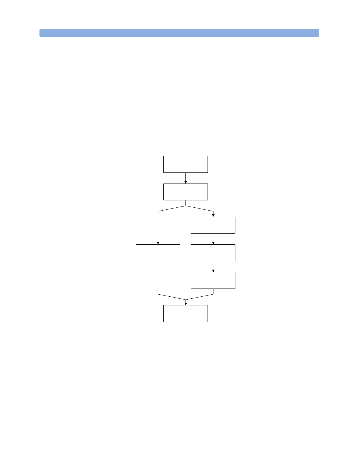
The following figure provides an overview of the workflow.
Define files to be
generated
Set up pat tern in GUI
Generate frame file
Generate frame file
and segment fi les
Import segment files
Figure 1 SONET Workflow
The following steps have to be performed to generate SONET frames
for ParBERT:
1. If not all files are needed, the files to be generated can be selected.
The dialog box for this is opened over File -> Generation Setting.
By default, all files are selected.
See “Selecting the Files to be Generated” on page 11 for details.
Edit frame file
Generate segment
files
into ParBERT
Agilent 81250 ParBERT SONET/SDH Frame Generator, November 2002 7
Page 8

Using the Frame Generator Generating Frame Files
2. The settings for the frames to be generated are made on the GUI.
See “How Frames are Generated” on page 13 for information about
the Frame Generator.
3. The selected files are generated by selecting the File Save Menu
button.
This opens the Save as dialog box, where you can select the file
name and path for the files to be generated.
See “Generating Frame Files” on page 8 for details.
4. Import the files into ParBERT.
See “Importing Frames into ParBERT” on page 9 for more
information.
In case the frames have to be modified, the following must be done:
5. The frame files are edited. Any text editor can be used for this (that
can handle the size), such as WordPad.
“Editing Frame Files” on page 9 provides notes about what should
be considered when editing frame files.
6. The segment files are generated from the frame files by selecting
File -> Convert Frame(s).
This generates the necessary segment files for the ParBERT
analyzer and generator.
See “Converting Frame Files” on page 12 for more information.
You can then import these files to ParBERT.
Generating Frame Files
The GUI provides various fields for configuring the patterns. See
“Graphical User Interface Reference” on page 23 for information
about the various GUI elements.
It is recommended to read “How Frames are Generated” on page 13.
Here you can find information about SONET frames, and how the
various frame sections are manipulated.
When you have made your settings, select File -> Save as, click File
Save Menu, or click the Save File button. This opens up the Save As
dialog box, where you can select the file path and name.
8 Agilent 81250 ParBERT SONET/SDH Frame Generator, November 2002
Page 9

Importing Frames into ParBERT Using the Frame Generator
Importing Frames into ParBERT
When the frames have been generated, they have to be imported to
ParBERT, where SONET tests can then be carried out.
Editing Frame Files
The Frame Generator allows one or more structured patterns (or
frames) to be specified and generated. The pattern is written into a
frame file and/or segment file. The segment file can be imported into
the ParBERT.
The following is an example of the start of an *.hfm file.
#Col. Rows of OC-3 Rows of ignore_flags
# R1 R2 R3 R4 R5 R6 R7 R8 R9 R1 R2 R3 R4 R5 R6 R7 R8 R9
#-------------------------------------------------------------------------C1.1 f6 0 ff 6a 0 0 0 0 0 0 0 0 0 0 0 0 0 0
C1.2 f6 0 55 6a 0 0 0 0 60 0 0 0 0 0 0 0 0 0
C1.3 f6 0 aa 6a 0 0 0 0 60 0 0 0 0 0 0 0 0 0
#-------------------------------------------------------------------------C2.1 28 0 aa a 0 0 0 0 60 0 0 0 0 0 0 0 0 0
C2.2 28 0 55 a 0 0 0 0 0 0 0 0 0 0 0 0 0 0
C2.3 28 0 f0 a 0 0 0 0 0 0 0 0 0 0 0 0 0 0
#-------------------------------------------------------------------------C3.1 1 0 0 0 0 0 0 0 0 0 0 0 0 0 0 0 0 0
C3.2 1 df 0 0 0 0 0 0 0 0 0 0 0 0 0 0 0 0
C3.3 1 0 0 0 0 0 0 0 0 0 0 0 0 0 0 0 0 0
#-------------------------------------------------------------------------C4.1 0 0 0 0 1 1 0 0 0 0 0 0 0 0 0 0 0 0
C4.2 0 0 0 0 1 1 0 0 0 0 0 0 0 0 0 0 0 0
C4.3 0 0 0 0 1 1 0 0 0 0 0 0 0 0 0 0 0 0
#-------------------------------------------------------------------------C5.1 0 0 0 0 0 0 0 0 0 0 0 0 0 0 0 0 0 0
C5.2 0 0 0 0 0 0 0 0 0 0 0 0 0 0 0 0 0 0
C5.3 0 0 0 0 0 0 0 0 0 0 0 0 0 0 0 0 0 0
#-------------------------------------------------------------------------C6.1 0 0 0 0 0 0 0 0 0 0 0 0 0 0 0 0 0 0
C6.2 0 0 0 0 0 0 0 0 0 0 0 0 0 0 0 0 0 0
C6.3 0 0 0 0 0 0 0 0 0 0 0 0 0 0 0 0 0 0
#-------------------------------------------------------------------------C7.1 0 0 0 0 0 0 0 0 0 0 0 0 0 0 0 0 0 0
Agilent 81250 ParBERT SONET/SDH Frame Generator, November 2002 9
Page 10

Using the Frame Generator Editing Frame Files
C7.2 0 0 0 0 0 0 0 0 0 0 0 0 0 0 0 0 0 0
C7.3 0 0 0 0 0 0 0 0 0 0 0 0 0 0 0 0 0 0
#-------------------------------------------------------------------------C8.1 0 0 0 0 0 0 0 0 0 0 0 0 0 0 0 0 0 0
C8.2 0 0 0 0 0 0 0 0 0 0 0 0 0 0 0 0 0 0
C8.3 0 0 0 0 0 0 0 0 0 0 0 0 0 0 0 0 0 0
These files can be edited by any editor as text file. For better
recognition of the relevant lines, each line begins with a counter with
the format C<column>.<sts-nr>.
Please note the following when you edit frame files:
• It is recommended only to edit patterns that have not been
scrambled. Otherwise, the changed bytes have to be scrambled
manually.
• “#” comments out a line (you can add any number of comment
lines).
• Do not edit parity bytes. When frame files are converted, all parity
bytes are recalculated. Any changes you made to parity bytes are
lost.
• The synchronizing pattern in row 3, column 1 to 6 may be edited.
However, there may be problems if this pattern is not unique within
the frame.
10 Agilent 81250 ParBERT SONET/SDH Frame Generator, November 2002
Page 11

Selecting the Files to be Generated Using the Frame Generator
Selecting the Files to be Generated
You can optionally select the files to be generated. By default, all files
are generated. You can change this selection in a dialog box that opens
when you select File -> Generation Setting.
Figure 2 File generation dialog box
You can select from the following files:
• Frame Files (*.hfm)
These files are in an human-readable intermediate format that can
only be interpreted by the SONET tool.
• Analyzer Files (*_ana.seg)
These files are imported into ParBERT for the analyzer.
• Generator Files (*_gen.seg)
These files are imported into ParBERT for the generator.
• B Bytes Files (*.bbs)
These files are for information only about the generated parity bytes
(B1 to B3 bytes).
Automatic Production If you are not going to edit the frame files, you have to select Analyzer
File and Generator File.
Manual Production If you are going to edit the frame files, you only have to select Frame
File.
Agilent 81250 ParBERT SONET/SDH Frame Generator, November 2002 11
Page 12

Using the Frame Generator Converting Frame Files
Converting Frame Files
Once the frame files have been generated (and edited), they must be
converted to segment files for use by ParBERT.
This is done by the following:
• Selecting File -> Convert Frame(s).
• Clicking the Convert Frames button.
These both open the Open dialog box, where you can select the *.htm
file to be converted.
After you have entered a file name and clicked Open, the following
dialog box should appear:
Figure 3 Convert Files dialog box
The Scrambler should be set to On, the Segment width can be
adjusted.
See also “Scrambler” on page 24 and “Segment width” on page 25.
The text in the dialog box indicates which files will be generated. If
files that you need are not listed (for example, if you need to generate
segment files for the analyzer, but these are not shown), or if an error
message appears, check the settings in the Generation Settings dialog
box (see “Selecting the Files to be Generated” on page 11).
These files will be generated and overwritten without any further
notice. If you want to save the files under different names, you have to
click Change instead of OK.
This opens the Open dialog box, where you can enter a different file
name for each file to be generated. After you have changed or accepted
all file names, the files are converted.
12 Agilent 81250 ParBERT SONET/SDH Frame Generator, November 2002
Page 13

How the Frame Generator Works
The following sections provide detailed specifications of the following:
• How the Frame Generator generates frames
This is described in the following section.
• Coded Mark Inversion (CMI) coding
See “CMI Coding” on page 20.
• Synchronizing pattern
See “Synchronizing Pattern” on page 20.
How Frames are Generated
The Frame Generator generates frames based on the settings made in
the GUI. The following figure shows the different components of a
frame.
Secti on/RS overhead
Admi ni strati ve uni t pointer(s)
Path Over head
Line/MS overhead
Transport Overhead Payload
Figure 4 SONET Frame Structure
Agilent 81250 ParBERT SONET/SDH Frame Generator, November 2002 13
Page 14

How the Frame Generator Works How Frames are Generated
See the following sections for more information:
• “SONET Section Overhead and SDH RS Overhead Details” on
page 18
This section describes how the section overhead is generated.
• “SONET Line Overhead and SDH MS Overhead Details” on page 17
This section describes how the line overhead and multiplexer
overhead are generated.
• “SONET Path Overhead and SDH HP Overhead Details” on page 16
This section describes how the path overhead is generated.
• “Payload Details” on page 15
The section describes how the payload is generated.
BIP Coding
The SONET specification calls for Bit Interleaved Parity (BIP) of error
monitoring. For the monitored section of signal, an error code is
defined so that all there is an even number of 1s in the X bits, counting
the monitored section and the error code. This is illustrated in the
following figure.
Even number
of 1s
Figure 5 BIP-8 coding
To ensure that the signal is correctly transferred, the error code byte
of one frame is stored in a byte of the next frame. The receiver
compares the calculated parity with the byte stored in the next frame
to determine if the frame arrived correctly.
X bi ts
1 0 1 1 0 0 1 1
1 1 0 1 0 0 0 1
1 0 1 1 1 1 0 1
0 1 1 1 0 1 1 1
1 0 1 1 0 0 1 1
0 0 0 1 1 0 1 1
Error code
of f r ame
14 Agilent 81250 ParBERT SONET/SDH Frame Generator, November 2002
Page 15

How Frames are Generated How the Frame Generator Works
Payload Details
The payload choices are:
All 1s, all 0s, alternate 1s and 0s, various PRBS options, a binary file
and a pattern editor.
It is important to consider the possible lengths of the PRBS with
respect to the supported frame sizes. The following table shows the
payload sizes generated at various rates:
Table 1 Rates and payload sizes
Rate Payload size
STS-768 4.755.456 bits
STS-192 1.188.864 bits
STS-48 297.216 bits
STS-12 74.304 bits
STS-3 18.576 bits
The PRBS have the following lengths and polynomials:
Table 2 PRBS lengths and polynomials
PRBS Length Polynomial
PRBS 5 31 bits x
PRBS 7 127 bits x
PRBS 9 511 bits x
PRBS 11 2,047 bits x11 + x9 + 1, not inverted as CCITT 0.152
PRBS 15 32,767 bits
a
PRBS 20 1,048,575 bits
PRBS 23 8 388,607 bits
PRBS 31 2,147,483,657
c
bits
a
Fits within an STS-48 frame.
b
Fits within an STS-192 frame.
c
Exceeds the STS-768 frame size, but is included to provide some longer runs.
The PRBS generators are initialized to all ones. The ones are shifted to
the left by the number of bits expressed by the order of the polynomial
(for example, PRBS 7:
0xffffffff << 7
5
+ x4 + x2 + x1 + x0
7
+ x6 + x0, inverted
9
+ x5 + x
0
x15 + x14 + 1, inverted, as CCITT 0.151
b
x20 + x17 +1, not inverted as CCITT 0.151
c
x23 + x18 +1, inverted, as CCITT 0.151
X31 + X28 + x
0
).
The PRBS runs continuously and bulk-fills all payload bytes.
The payload fill starts at channel 1, row 1, column 5.
Agilent 81250 ParBERT SONET/SDH Frame Generator, November 2002 15
Page 16

How the Frame Generator Works How Frames are Generated
NOTE Please pay attention to the following when defining the payload fill.
• This is a bulk fill of the payload space, not a fill of each individual
payload channel.
• Since this is a repeating frame, there is a discontinuity of the PRBS
at the boundary between the last payload byte and the first payload
byte in the next transmitted frame if the number of generated
frames is not a multiple of the PRBS length (for example, 2
frames are needed to create a continuous PRBS 7 payload).
• The fill start address of the PRBS payload is channel 1, row 1,
column 5, which corresponds to a pointer with the address of
522
.
Dec
• When a binary file is selected as payload, there will be a chance that
the synchronizing pattern for the ParBERT appears also within the
payload. If so, the ParBERT will not be able to synchronize.
7
– 1
SONET Path Overhead and SDH HP Overhead Details
This section describes how the path overhead is handled (and
manipulated) with the application.
B3 Byte
General A path error monitoring function is implemented in the SONET
specification. This function is incorporated as BIP-8 code, which is
stored in the B3 byte of each frame. See “BIP Coding” on page 14 for
details about BIP-8 coding.
The path error monitoring code of a frame is calculated from the path
overhead and payload of the previous frame (and includes the frame’s
B3 byte).
Single B3 Error When a BIP (B3) error is selected, a single B3 error per frame is
generated.
To generate a B3 error (in channel one only), one bit in a selected
payload byte is complimented (that is, it is XORed with
0000 0100
).
The selected payload byte is the byte positioned to the right of the B3
byte, located at channel 1, row 6, column 5. The B3 byte itself remains
unchanged.
16 Agilent 81250 ParBERT SONET/SDH Frame Generator, November 2002
Page 17

How Frames are Generated How the Frame Generator Works
G1 Path Status Byte
The G1 path status byte is affected by the following alarms:
• L-AIS / MS-AIS
•HP-REI
• L-RDI / MS-RDI
Depending on which alarm is selected, the G1 path status byte is
affected as follows:
•No errors:
•AIS on:
•HP-REI:
0000 0000
xxxx 0111
0001 0000
All Other Path Overhead
All other path overhead bytes will contain
scrambling.
0000 0000
prior to
SONET Line Overhead and SDH MS Overhead Details
Pointer Bytes
All H1 bytes will be set to “not new data” and contain offset zero
(
0110 0000
All H2 bytes will contain offset zero (
All H3 bytes are undefined when there are no pointer negative
justifications; (pointer increment and decrement are not available), H3
will be used to allow a fixed B2 value, see “Single B2 Error” on
page 18 below.
).
0000 0000
).
K2 Byte
The K2 byte is only set for the first frame.
It is affected by the following alarms:
• L-AIS / MS-AIS
• L-RDI / MS-RDI
Agilent 81250 ParBERT SONET/SDH Frame Generator, November 2002 17
Page 18

How the Frame Generator Works How Frames are Generated
Depending on which alarm is selected, the K2 byte is set as follows:
•No errors:
•AIS on:
•RDI on:
For the alarm condition, no other action is taken concerning any
payload or other overhead bytes, these are all unchanged from the
normal (no errors) state.
The K2 bytes in all other frames are unused and are set to
0000 0000
0000 0111
0000 0110
B2 Bytes
General A path error monitoring function is implemented in the SONET
specification. This function is incorporated as BIP-8 code, which is
stored in the B2 bytes of each frame. See “BIP Coding” on page 14 for
details about BIP-8 coding.
The path error monitoring code of a frame is computed over all bits of
the previous STM-N frame, except for the first three rows of SOH, and
is placed in the B2 bytes of the current frame before scrambling.
Single B2 Error You can specify a single B2 error per frame.
0000 0000
.
To generate a B2 error (in channel one only), bit 3 in the pointer H3
byte is complimented.
The B2 byte itself remains unchanged.
All Other Line Overhead
All other line overhead bytes contain
0000 0000
prior to scrambling.
SONET Section Overhead and SDH RS Overhead Details
B1 Byte
General A section error monitoring function is implemented in the SONET
specification. This function is incorporated as BIP-8 code, which is
stored in the B1 bytes of each frame. See “BIP Coding” on page 14 for
details about BIP-8 coding.
The section error monitoring code of a frame is computed over all bits
of the previous STM-N frame after scrambling, and is placed in the B1
byte of the current frame before scrambling.
18 Agilent 81250 ParBERT SONET/SDH Frame Generator, November 2002
Page 19

How Frames are Generated How the Frame Generator Works
Single B1 Error The user can specify a single B1 error per frame.
To generate a B1 error (for channel 1 only), one 1 of a selected byte is
complimented (the byte is XORed with
The selected byte is located at channel 1 (SONET) or channel 1-a
(SDH), row 3, column 1. This byte is unused by the signal.
The B1 byte itself remains unchanged.
0000 0001
).
Framing
A complete framing pattern (3, 12, 48, 192, 768 x F6 + 3, 12, 48, 192,
768 x 28) is generated.
Out Of Frame (OOF)
Out Of Frame is generated by inverting the first A1 byte (F6 becomes
09), and the first A2 byte (28 becomes D7).
J0/Z0 Section Trace/Growth Bytes
For SONET, the STS-768 ID J0 byte will always be 1.
For SDH, the STM-256 ID J0 bytes will be numbers 1, 2, 3 to 0.
For SDH, the undefined Z0 bytes will be set to
physical sequence will be: 1, 2, 3, 4, ... 255, 0, AA, AA, ... AA, AA).
Similar numbering applies to all other frames.
AA (1010 1010
) (the
All Other Section Overhead
All other section overhead bytes will contain
scrambling, except the D1, D2 and D3 bytes, which are used for
synchronizing.
0000 0000
prior to
Agilent 81250 ParBERT SONET/SDH Frame Generator, November 2002 19
Page 20

How the Frame Generator Works CMI Coding
CMI Coding
CMI coding is a method of converting binary data into an electrical
signal. Bits with the value
positive/negative voltages). Bits with the value
two voltage levels, a negative then positive level, within the same time
span normally used for one digit. This type of code maintains the
signal at the digital clock rate, improving signal synchronization.
1
are given bipolar levels (alternating
0
are represented by
For example: Binary
is converted to:
NOTE When CMI coding is used, the frequency of the ParBERT has to be
doubled.
NOTE There are a few combinations of settings where the generated
synchronizing pattern is not unique (for example, segment width 8,
STS 48 and STS 192). This can be a problem with very regular CMI
pattern but should not appear with other widths.
01101011
01 11 00 01 11 01 00 11
Synchronizing Pattern
ParBERT needs a synchronizing pattern of 48 bits per channel (where
segment width = 1). This pattern is inserted in the D1, D2 and D3 bytes
of the section overhead as long as needed.
Lower rates are restricted to lower segment widths (see table below).
The following patterns are used:
• For scrambled and non-scrambled frames:
Five fixed bytes:
Followed by one counter byte:
The complete pattern would be, for example:
0xff 0x55 0xaa 0xaa 0x55 0x f0
• For CMI-coded frames (doubled frequency):
0xff 0x55 0xaa 0xaa 0x55
0xf0, 0xe1
, ...
0x0f
0xf5 0xaa 0x5f
20 Agilent 81250 ParBERT SONET/SDH Frame Generator, November 2002
Page 21

Synchronizing Pattern How the Frame Generator Works
When inserting a binary payload, you have to make sure that this
pattern (with scrambling) is not used within the payload.
The following table shows how the payload size is determined by the
segment width and the different rates.
Table 3 Possible Combinations of Rate and Segment Width
Segment width
a
STM-1 /
STS-3
STM-4 /
STS-12
STM-16 /
STS-48
STM-64 /
STS-192
STM256 /
STS-768
1 48 Bits 48 Bits 48 Bits 48 Bits 48 Bits
2
4
96 Bits 96 Bits 96 Bits 96 Bits 96 Bits
192 Bits 192 Bits 192 Bits 192 Bits 192 Bits
8 384 Bits 384 Bits 384 Bits 384 Bits 384 Bits
12
16
576 Bits 576 Bits 576 Bits 576 Bits 576 Bits
768 Bits 768 Bits 768 Bits 768 Bits 768 Bits
D1-D3 (in Bits) 72 Bits 288 Bits 1152 Bits 4608 Bits 18432 Bits
a
Note: The areas in gray are unavailable combinations.
Agilent 81250 ParBERT SONET/SDH Frame Generator, November 2002 21
Page 22

How the Frame Generator Works Synchronizing Pattern
22 Agilent 81250 ParBERT SONET/SDH Frame Generator, November 2002
Page 23

Graphical User Interface Reference
The Frame Generator’s Graphical User Interface (GUI) is relatively
simple; the following is a short description of the GUI elements, tool
bar and menus.
Menus
To o l b ar
Settings area
Status bar
Figure 6 SONET GUI
Agilent 81250 ParBERT SONET/SDH Frame Generator, November 2002 23
Page 24

Graphical User Interface Reference Settings Area
Settings Area
NOTE Some elements of the setting area are invisible if you select CID for
Mode. The invisible elements are not available for CID.
The following is a list of the elements of the settings area:
• Mode
Defines the following modes.
– Normal specifies a single frame of a SONET/SDH signal.
– CID specifies a Consecutive Identical Digit pattern.
• Format
Defines the frame format to be generated; can either be SONET,
SONET-C, or SDH.
• Scrambler
Determines whether or not the payload is scrambled. The SONET /
7
SDH 2
• CMI
Defines whether or not the frame is coded in the Coded Mark
Inversion format, which means doubled frequency.
If you select CMI, make sure you double the frequency on the
ParBERT.
See “CMI Coding” on page 20 for more information.
• Frame(s)
– Single specifies one pattern.
– Multiple lets you select the number of patterns to be generated.
NOTE When setting up the frame files, please keep the ParBERT memory
restrictions in mind. The available memory depends on the data
generator/analyzer modules installed and on the port frequency.
For example, a ParBERT 43G system equipped with eight E4861B
modules and running at a data rate above 42.67 Gbit/s can have a
memory capacity of 16 Mbit per channel.
PRBS standard is used for scrambling.
Determines how many patterns are to be generated in the frame
file.
24 Agilent 81250 ParBERT SONET/SDH Frame Generator, November 2002
Page 25

Settings Area Graphical User Interface Reference
• Rate
The rate available depends on the selected Format. The following
rates are available:
SONET (-C) SDH
STS-768 (39.81312 Gb/s) STM-256
STS-192 (9.95328 Gb/s) STM-64
STS-48 (2.48832 Gb/s) STM-16
STS-12 (622.08 Mb/s) STM-4
STS-3 (155.52 Mb/s) STM-1
• Payload
This field defines how the payload is generated. You have the
following choices:
–All 0s
–All 1s
– Alternate 1, 0
– Various PRBS settings
– Edit pattern
This opens the Pattern Editor, which allows you to enter a
pattern (see following description).
– From file
This opens up a dialog box, where you can select the file to be
used as payload.
This must be a binary file.
See “Payload Details” on page 15 for more information.
• Segment width
Lets you define the segment width used. This has to match
multiplexer type used.
• Pattern Editor
Allows you to define a pattern (
generated. The bits entered are repeated to fill up the payload.
0
s and 1s) for the payload to be
Agilent 81250 ParBERT SONET/SDH Frame Generator, November 2002 25
Page 26

Graphical User Interface Reference Settings Area
• Errors
Allows you to specify errors that are to be generated in the first
frame.
SONET (-C) SDH
S-BIP (B1) RS-BIP (B1)
L-BIP (B2) MS-BIP (B2)
P-BIP (B3) HP-BIP (B3)
None None
• Alarms
Allows you to specify alarms that are to be generated in the
patterns.
SONET (-C) SDH
OOF OOF
L-AIS MS-AIS
L-FERF MS-RDI
P-FEBE HP-REI
None None
• Mask Analyzer B Bytes
When you select this option, the B bytes (error monitoring bytes) for
the analyzer are masked.
• File Save Menu button
Opens the File Save dialog box, where you can select a file name and
path for the frame files to be generated. See “Generating Frame
Files” on page 8 for more information.
• Exit button
Closes the application.
26 Agilent 81250 ParBERT SONET/SDH Frame Generator, November 2002
Page 27

Menus Graphical User Interface Reference
Menus
The Frame Generator contains the following menus, which enable you
to save files and change appearances of the application:
• File menu
• View menu
• Help menu
These are described in the following sections.
File Menu
The File menu contains the following elements:
• Save as ...
Opens the File Save dialog box, where you can select a file name
and path for the frame files to be generated. See “Generating Frame
Files” on page 8 for more information.
• Convert Frames
Opens the Open dialog box, where you can select files that are to be
converted into frames that can be imported into ParBERT. See
“Converting Frame Files” on page 12 for more information.
• Exit
Closes the application.
• Generation Setting
Opens up a dialog box that lets you select which files are to be
generated. You can select any combination of the following:
– Frame Files
– Analyzer Files
– Generator Files
– B Bytes Files
See “Settings Area” on page 24 for more information.
Agilent 81250 ParBERT SONET/SDH Frame Generator, November 2002 27
Page 28

Graphical User Interface Reference To o l B ar
View Menu
The View menu contains the following elements:
• Tool Bar
Shows/hides the tool bar.
• Status Bar
Shows/hides the status bar.
Help Menu
The Help menu contains the following elements:
• about_frame_gen
Opens up a message box that informs you about the version number.
• Help
Opens the Online Help.
Tool Bar
The tool bar provides you quick access to most important Frame
Generator functions. The following tools are available:
Opens the Save as ... dialog box, where you can select the
name and path of the files to be saved. See “Generating
Frame Files” on page 8 for more information.
Opens the Open dialog box, where you can select the
previously generated files to be converted. See
“Converting Frame Files” on page 12 for more
information.
Opens a message box that informs you about the version of
the software.
28 Agilent 81250 ParBERT SONET/SDH Frame Generator, November 2002
Page 29

Status Bar Graphical User Interface Reference
Status Bar
The status bar at the bottom of the GUI provides information about the
status of the application. It also provides “pop-up” type tips for the
menus and tools (when the mouse moves over a tool, for example, the
status bar shows what the tool does).
Agilent 81250 ParBERT SONET/SDH Frame Generator, November 2002 29
Page 30

Graphical User Interface Reference Status Bar
30 Agilent 81250 ParBERT SONET/SDH Frame Generator, November 2002
Page 31

Index
Index
B
B1
byte 18
error 19
B2
byte 18
error 18
B3
byte 16
error 16
BIP coding 14
C
CMI coding 20
F
File generation 11
Files, overview 11
Frame
generation 13
Frame Generator
functionality 5
introduction 5
using 7
workflow 7
Frames
conversion 12
editing 9
generating 8
G
G1 byte 17
GUI
overview 23
settings area 24
H
HP overhead 16
J
M
Menus
File 27
Help 28
overview 27
View 28
O
OOF (Out Of Frame) 19
P
ParBERT, importing frames 9
Path overhead 16
Pattern, synchronizing 20
Pointer bytes 17
PRBS
lengths 15
polynomials 15
S
SDH MS overhead 17
SDH RS overhead 18
Section growth 19
Section overhead 18
Section trace 19
Software installation 5
Status bar 29
Synchronizing pattern 20
T
Tool bar 28
W
Workflow 7
Z
Z0 byte 19
J0 byte 19
K
K2 byte 17
L
Line overhead 17
Agilent 81250 ParBERT SONET/SDH Frame Generator, November 2002 31
Page 32

Index
32 Agilent 81250 ParBERT SONET/SDH Frame Generator, November 2002
 Loading...