

Page 1
Agilent 81200
The 81200 Data Generator/
Analyzer Platform
Configuration Guide
Release 2.1
Simplify your verification and characterization process
Page 2
The Agilent Technologies 81200
data generator/analyzer platform
The Agilent 81200 is a modular platform consisting of front-ends, modules, mainframes and user interfaces,
which can be tailored to your specific
test needs. This guide aims to help
you choose the right components. In
this context, two different fundamental possibilities in configuring the system must be considered. These depend
on how you want to integrate the
Agilent 81200 into your test environment:
a) Using the 81200 as a "proprietary
system" means that the 81200 will not
be combined with other VXI modules
in a standard VXI system. It can however, be controlled by a LAN or a
GPIB interface. If a "proprietary system" is desired, follow steps 1-3, 4a
and 5 to configure your system (figure 1).
b) If Agilent 81200 modules are combined with other VXI modules then
an "open VXI system" (the standard
VXI system), is achieved. For this
configuration, please follow steps 1-3,
4b and 5 (figure 1).
For information on upgrading an
existing Agilent 81200, please refer to
page 8.
On each page you'll find tables where
you can enter your choice as a
reminder for ordering.
STEP 1: Selecting the number
of channels required
Figure 2 shows that three different
generator front-ends and four different analyzer front-ends are available.
To select the correct front-end, the
following should be checked:
• speed
• data format
• levels
• memory depth
Please note that some of the lower
speed front-ends have two outputs or
two inputs and support a maximum
memory depth of 512 Kbit per channel, not 1024 Kbit. SMA cables are
not included.
For more details, consult the Agilent
81200 Data Generator/Analyzer
Platform, data sheet, p/n 5965-3415E.
STEP 2: Choosing the modules
The generator and analyzer frontends can be fitted together as follows:
• Generator front-ends can be fitted
(any mix) in the Agilent E4831A
Clock and Data Generator Module
or the Agilent E4841A Data
Generator/Analyzer Module.
• Analyzer front-ends only fit into
the Agilent E4841A module. Any
mix of analyzer and generator
front-ends is acceptable, provided
that the same sequence is needed
for the generator and analyzer.
• At least one clock module is essential; either an Agilent E4805A
Central Clock Module or the
Agilent E4831 Clock & Data
Generator Module. These modules
can drive up to eleven or six
Agilent E4841A modules respectively.
• The sequence of segments and the
segment types (pattern, pause,
PRBS/PRWS) is the same for all
the channels within one module.
For example, if you need to set up
PRBS and control channels, make
sure you run PRBS from one module and the control signals from
another module.
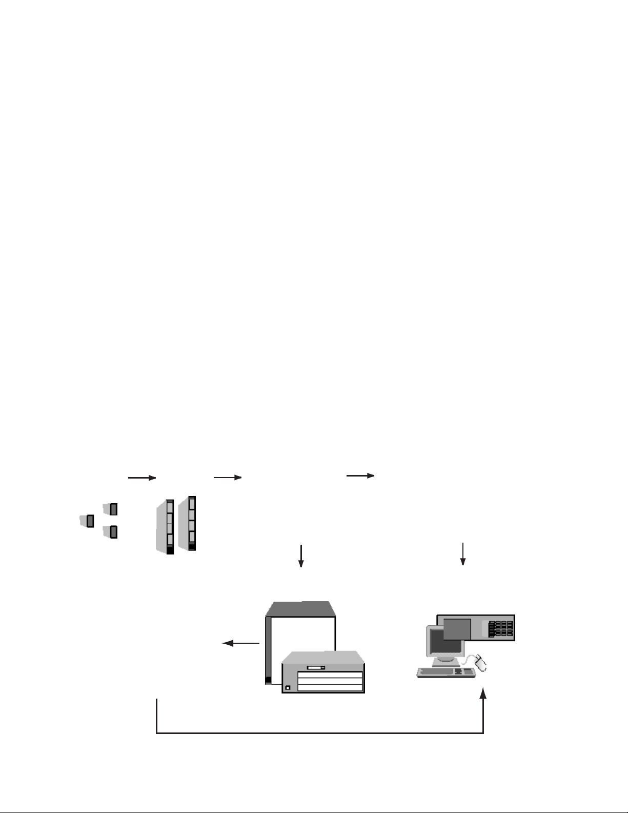
Figure 1: Configuring an Agilent 81200 Data Generator/Analyzer Platform
2
STEP 1 STEP 2
Front-ends
The front-ends determine
generator/analyzer function
and input/output characteristics.
System Configuration
You are then ready to configure your system
using the attached Agilent 81200 Configuration
Sheets on page 9.
Modules
A choice of modules provide
front-end-housing, clock
and sequencing capability,
or or combination of these features.
STEP 3
Decision: “Open VXI System”
Integrating the Agilent 81200 modules
with other VXI test equipment to a
open VXI system or use the Agilent 81200
as “proprietary system”
Propretiary System
STEP 4a
Mainframe(s) & System Configuration
There is a choice of two mainframes.
Both include software, PC, hard disk and floppy drive.
The larger frame can be augmented with one or two expander frames.
STEP 4b
Requirements for intergration
into an “open VXI system”:
VXI controller and slot 0 commander
recommendations and additional requirements
for operating the Agilent 81200 modules
in a open VXI environment.
STEP 5
Choose your user interfaces, support
options, hardware and software accessories
Page 3
3
Product Description Model Number Quantity
Generator front-ends Generator front-ends 660MHz, RZ/NRZ, 3.5 Vpp, variable transition times SMA (f). Agilent E4838A
Generator front-end 330 MHz, RZ/NRZ, variable transition times SMA (f). Agilent E4842A
Generator front-end 660 MHz, RZ/NRZ, single channel, 2.5 Vpp SMA (f). Agilent E4843A
Dual generator front-end 200 Mbit/s, NRZ, 3.5 VPP SMA (f). Agilent E4846A
Analyzer front-ends Differential analyzer front-end 660 Msa/s, 1 GHz bandwidth, 50Ω SMA (f). Agilent E4837A
Single analyzer front-end 660 Msa/s, 1 GHz bandwidth, 50Ω SMA (f). Agilent E4844A
Dual analyzer front-end 330 Msa/s, 1 GHz bandwidth, 50Ω SMA (f). Agilent E4845A
High impedance dual analyzer front-end 330 Msa/s, 350 MHz bandwidth, 50Ω SMA (f). Agilent E4847A
Modules 660 MHz data generator/analyzer module – holds four front-ends, any mix Agilent E4841A
660 MHz clock and data generator module – holds two generator front-ends, any mix.
Clocks up to six Agilent E4841A modules. Agilent E4831A
660 MHz central clock module, which clocks up to eleven Agilent E4841A modules Agilent E4805A
and up to two Agilent E4805s.
Required in all systems that include analyzer front-ends, and for all systems with seven Agilent E4805A
or more Agilent E4841As.
8-line trigger input for TTL signals. When branching on external events Agilent E4805A
(hardware signals) other than VXI-ECL trigger lines or compare errors is required. Opt 002
Deskewprobe, includes Agilent 1144A 880 MHz active probe and a BNC (f) to SMA (m) Agilent E4805A
adapter (part number 1250-1200). Opt 003
Which clock module?
The Agilent E4831A Clock & Data
Generator Module can be an economic way of building pulse or
data generators as it includes slots
for two front-ends. Please remember that the Agilent E4831A can
only be used for generator channels. For applications needing
many channels, analyzer channels
or more than two looping levels,
use the Agilent E4805A Central
Clock Module.
STEP 3: Decision - VXI integration
or not
If you want to combine the Agilent
81200 modules with other VXI
modules to achieve an "open VXI
system," then go to STEP 4b.
If you want to use the Agilent
81200 as a “proprietary system,”
meaning the Agilent 81200 will not be
combined with other VXI modules in
one system, then go to STEP 4a.
STEP 4a: Selecting the mainframe
If you’ve made the decision to configure a "proprietary system," you are
now in the position to select a mainframe. Two mainframes are available,
the Agilent E4840A small frame with
three free slots and the Agilent
E4849B mainframe with 10 free
slots. Both mainframes include a
built-in PC running Windows NT
4.0®. The user software is also
installed. All modules and front-ends
ordered with the mainframes come
factory installed.
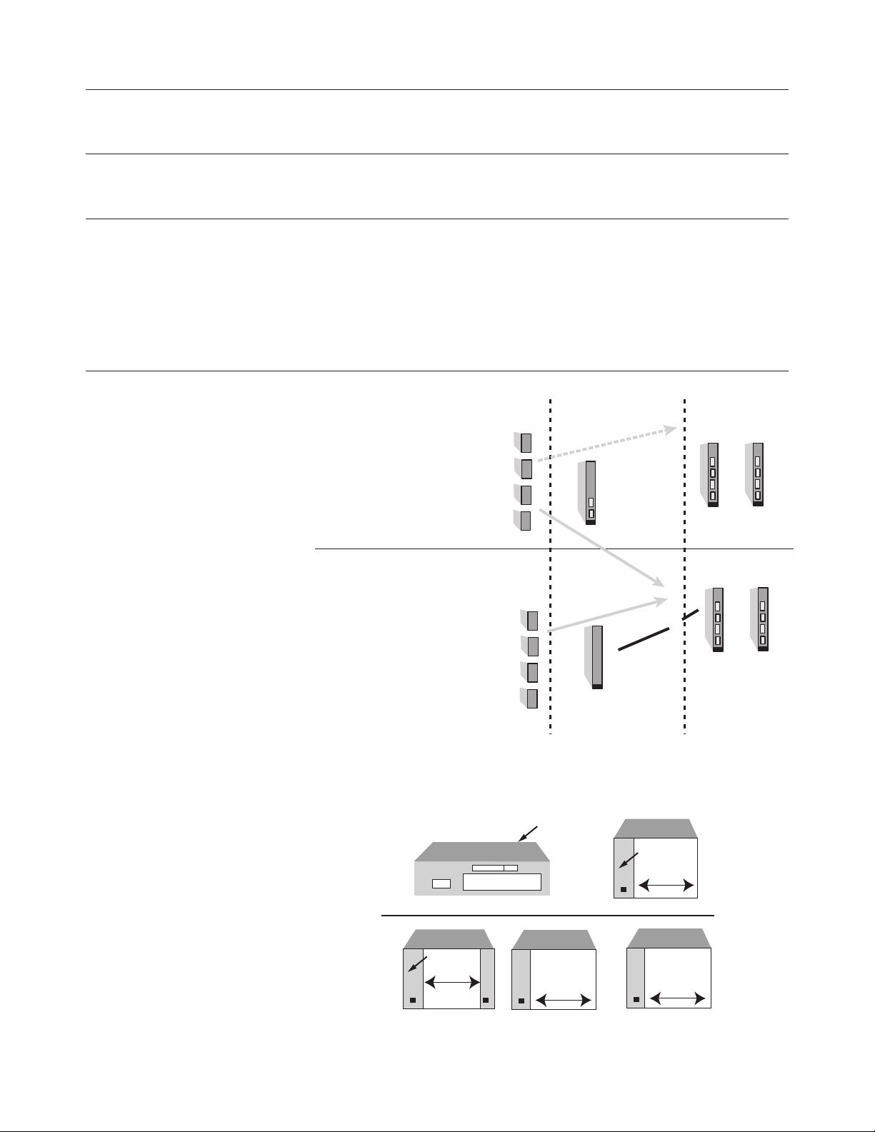
Figure 2: Front-ends and modules
Figure 3: Mainframes and expanders
Generator-only systems.
(Two looping levels)
Agilent E4838A 660 MHz/MRZ
Agilent E4842A 330 MHz RZ/NRZ
(variable transitions)
Agilent E4843A 660 MHz RZ/NRZ
Agilent E4846A Dual 200 Mb/s, NRZ
Front - ends Clock module Data generator/
+
Agilent
E4831A
Clock & data
generator module
+
Generator systems or generator/analyzer systems.
Analyzer front ends
(Five looping levels)
analyzer modules
Up to six Agilent E4841A
modules can be added when
more generator front-ends are needed.
Agilent E4837A 660 MSa/s, differential
Agilent E4844A 660 MSa/s
Agilent E4845A Dual 330 MSa/s
Agilent E4847A High-impedance
dual 330 MSa/s
Up to 8 front-ends
Agilent E480A
3 free slots
3-slot PC
9 free slots
VXI bus
extender
Embedded PC
+
VXI bus
extender
12 free slots
Agilent E4805A
Central clock module
Up to 36 front-ends
Agilent E4849B
3-slot PC
10 free slots
(+)
VXI bus
extender
12 free slots
+
Agilent E4841A
Data generator/
analyzer module(s)
Page 4
4
Expander frames
For more module slots, one or two
Agilent E4848B expander frames can
be connected. To do this, a VXI extender module (Agilent E4849B Opt 002)
is required. The module occupies one
of the otherwise free slots and is connected to a corresponding VXI extender that is supplied as part of the
expander frame.
Note that, when one or two expander
frames are fitted, an Agilent E4805A
Central Clock Module must be included in all frames. The Agilent E4831A
Clock & Data Generator Module is
unsuitable for systems with expander
frames.
Personalized system configuration
Now you are in a position to configure your system to meet your specific
requirements with the Agilent 81200
Configuration Sheets. For configuration instructions, please consult the
box on page 9. If you do not fill out
the configuration sheets, your system
will be delivered with the conventional configuration pre-installed. Now go
to STEP 5.
STEP 4b: Integrating Agilent 81200
modules with other VXI test equipment
To run the Agilent 81200 modules in
a standard VXI test system with other
VXI test equipment, it is necessary
that a controller with the operating
system Windows NT 4.0® is present,
on which the Agilent E4873A User
Software for the Agilent 81200 can
run. Therefore, either an embedded
VXI controller, or a Slot 0 command
module has to be installed in the
mainframe. The command module
has to be connected to an external
PC, on which the Agilent E4873A
User Software is running. For operating the Agilent 81200 platform in a
VXI test system, the following list,
comprising of VXI controllers, command modules and frames, is recommended. Please also refer to figure 4.
VXI Controller:
• Agilent E6235A VXI PC
• National Instruments VXIpc-850
Command modules:
• Agilent E1406A GPIB Slot 0
command module
• Agilent E8491B IEEE-1394 PC link
to VXI
• National Instruments MXI-2
Interface
Frames:
• Agilent E8403A VXI Mainframe, C-Size
Please consider the power requirement of the modules and front-ends
when you configure your VXI test system. For details about power requirements, consult Agilent 81200 Data
Generator / Analyzer Platform, data
sheets, p/n 5965-3415E, or download
the power requirement calculation
table (MS Excel) for the Agilent 81200
from:
www.agilent.com/find/81200_configinfo
It is necessary to order the Agilent
E4873A User Software for the Agilent
81200 separately.
Expander frames
For more module slots, one or two
Agilent E4848B expander frames can
be connected. To do this, a VXI extender module Agilent E1482B is
required. The module occupies one of
the otherwise free slots and is connected to a corresponding VXI extender that is supplied as part of the
expander frame.
Note that, when one or two expander
frames are fitted, an Agilent E4805A
Central Clock Module must be included in all frames. The Agilent E4831A
Clock & Data Generator Module is
unsuitable for systems with expander
frames.
Product Description Model Number Quantity
Mainframes Small mainframe – 3 free slots. Agilent E4840A
Mainframe – 10 free slots Agilent E4849B
VXI extender module (E1482B, 1 slot) Agilent E4849B
Required if 1 or 2 expander frames Opt 002
are needed
Expander frame Agilent E4848B
Software Agilent 81200 User Software Agilent E4873A
5 licenses of Agilent 81200 User Software Agilent E4873A
Opt 005
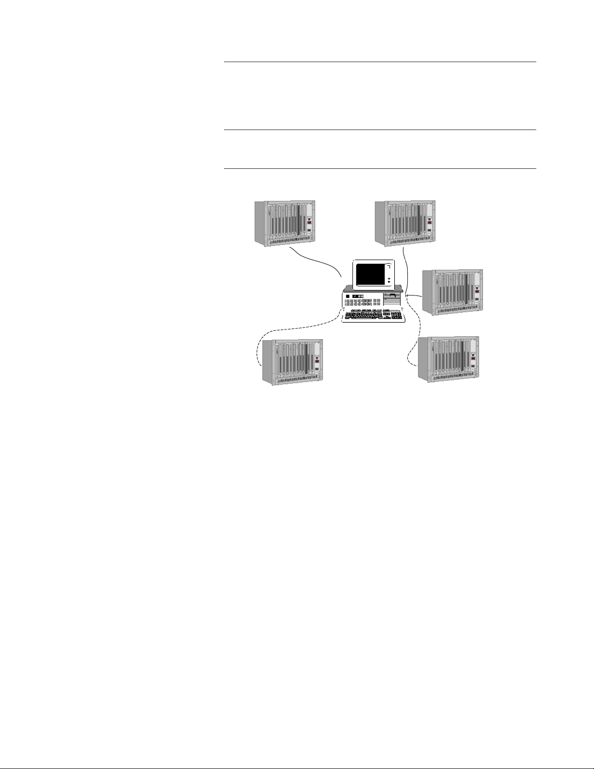
Figure 4: Recommended Standard VXI Interfaces
Open VXI Interfaces
VXI Mainframe
with E1406A GPIB
Slot 0 Command Module
Any PC running MS Windows NT 4.0®
VXI Mainframe
with Agilent E6235A
VXI-PC
VXI Mainframe
with Agilent E8491A
IEEE-1394 PC-link to VXI
VXI Mainframe
with National
Instruments
VXIpc- 850
Page 5
STEP 5: Choosing the user interface, support options, installation
options, and test accessories
User Interface
The compact choice is the display
and entry panel that mounts onto the
front of the mainframe and hinges for
optimum viewing/connector access. It
can only be used when connected to
the frames Agilent E4840A and
Agilent E4849B in the “proprietary
system.”
Alternatively, a VGA display, PC keyboard and mouse provide a larger,
higher resolution display and standard-sized keys.
Support, documentation and rackmount
options
Please consult the table below.
We recommend that a CD-ROM drive
is ordered so that user software
upgrades can be installed.
Figure 5: User interfaces
Product Description Model Number Quantity
Agilent E4840A/49B
Agilent E4840A/49B
User interface options 5" x 4" display and entry panel Opt 001
Interface options 15" VGA monitor Opt 003
17" VGA monitor Opt 004
21" VGA monitor Opt 005
Keyboard, US/English Opt 006
Mouse (two button) Opt 007
CD-ROM SCSI drive – includes SCSI-2 cable and termination Opt 008
Documentation options Additional user manual set Opt OB1
Japanese localization Opt ABJ
CD-ROM Service Guide (part number E4849-91022) Opt OBW
Rackmount options Rack flange kit (part number E8400-80923)
(Only for the Agilent E4849B and Agilent E4848B) Opt AX4
Support options One year on-site warranty Opt W01
Five year return repair service Opt W50
Software update notification service (12 per year) Opt +NAO
Commercial calibration with test report Agilent E4805A/31A/41A Opt UK6
Five year return calibration with service Agilent E4805A/31A/41A Opt W52
5
The following user interfaces are available
as Agilent E4840/49B mainframe options:
Option 001 display and entry panel
Includes 5"x 4" flat VGA display,
miniature keyboard and touch pad
Option 003/004/005:
15"/17"/21" Ultra VGA displays
Option 006 keyboard (U.S./ English)
and option 007 mouse
Page 6

6
Controlling instruments with the Agilent
81200 (only for "proprietary systems")
The embedded PC of the frames
Agilent E4849B and Agilent E4840A
includes a GPIB interface so that
other GPIB instruments can be controlled with the Agilent 81200 platform (figure 6). To do this, you need
to install suitable controller software
such as C or VEE. The GPIB interface
also allows the Agilent 81200 to be
controlled from another computer,
such as an ATE system controller.
Communicating over networks (only for
"proprietary systems")
The Agilent 81200's PC also includes
a LAN interface. The Agilent 81200
can be controlled from a network
computer and for convenient vector
transfer, servers may also be accessed
(figure 6). The data format used for
transferring vectors is a STIL
(Standard Test Interface Language)
subset (ASCII file with header and
footer). Vector files can also be transferred via 3.5" disks or the optional
external CD-ROM drive.
Additional test software for automated
characterization of your design
If you want to automate your characterization measurements and create
shmoo plots, jitter measurements and
eye diagrams, you can simply install
the Agilent E4974A Characterization
Software Components. For details,
also including the system requirements, please consult Agilent E4974A
Characterization Software
Components, data sheet, p/n 5968-
4259E.
Product Description Model Number Quantity
Agilent 81200 Agilent 81200 Test Fixture Agilent E4839A
dedicated Accessories
Pogo cable kit: 4*SMA(m) & 2 Pogo Agilent E4839A
adapter for the Agilent E4839A Opt. 001
Universal DUT Test Board Agilent E4839A
Opt. 002
Adapter Kit: 4*SMA(m) I/O Adapter Agilent 15440A
Test Software Characterisation Software Components
General Accessories Cable Kit: 4*SMA(m) to SMA(m) Agilent 15442A
Cable Kit: 10*SMA(m) to SCI Connector Agilent 15441A
SMA coax. cable, 1 m. Agilent 8120-4948
Torque wrench, SMA. Agilent 8710-1582
Adapter Kit: 4* SMA(m) I/O Adapter Agilent 15440A
Adapter SMA (m)/BNC (f). Agilent 1250-1200
Adapter right-angle SMA (m-f). Agilent 1250-1249
Adapter right-angle SMA (m-m). Agilent 1250-1397
Adapter tee SMA. Agilent 1250-1698
Pulse adder/splitter, SMA. Agilent 11667B
500 ps transition converter. Agilent 15433B
1 ns transition converter. Agilent 15434B
2 ns transition converter. Agilent 15438B
Cable, GPIB. Agilent 10833B
VEE 5.0 on CD-ROM. Agilent E2120F
BASIC on 3.5" disks. Agilent E2060B
Figure 6: The Agilent 81200 can be integrated into all common system
test environments
The supplied GPIB interface
let's you use the Agilent
81200's built-in PC as a test
system controller
The Agilent 81200 can be
integrated into a
GPIB test system
The Agilent 81200 can be
integrated into LAN's
Agilent 81200 (E4840A or E4849B mainframe)
with Windows-NT -based C,
HP-Basic or VEE
Other GPIB instruments
GPIB
Any controller or PC with C,
C++, HP-BASIC or VEE
LAN
Other GPIB instruments
Agilent 81200
(E4840A or E4849B mainframes)
Server/Hard disk
(STIL subset)
Agilent 81200 (E4840A
or E4849B mainframes)
VXI system
VXI system
Page 7

7
DUT Fixturing
For convenient and reliable DUT fixturing for DUT’s with up to 192 pins,
there is the Agilent E4839A Test
Fixture available. For details, please
consult Agilent E4839A Test Fixture,
data sheet, p/n 5968-3580E.
Simulation data link for VHDL and Verilog
BestLink/81200, a simulation data
link is available to process and transfer simulation data from Verilog and
VHDL simulators. For details, please
consult the BestLink/81200
Simulation Data Link for the Agilent
81200, product information, p/n
5968-2548E or visit:
www.diagonal.com
Test accessories
Please consult the table on page 6.
STEP 6: Checking your configuration
Front-ends and modules:
What do I need to run generator channels
up to 1.32 Gbit/s?
You need two Agilent E4843A or
Agilent E4838A generator front-ends,
which are EXOR-ed internally added
to generate one 1.32 Gbit/s signal. For
better signal performance, for signals
above 1 Gbit/s, please also consider
an external addition, by using an
Agilent 11667B (APC-3.5 power splitter, DC to 26.5 GHz) or an Agilent
11636B (DC to 26.5 GHz power
divider, APC-3.5).
For operation in EXOR addition mode
you only need two Agilent E4843A
respectively Agilent E4838A frontends per module.
I need generator channels that operate up
to 200 Mbit/s and with more than 512 Kbit
memory depth per channel. Can I use the
Agilent E4846A dual generator front-ends?
No. If you need more than 512 Kbit,
you should use the Agilent
E4843A/38A (max. 660 Mbit/s) frontends. The Agilent E4846A dual generator front-ends share the channel's
memory depth of 1024 Kbit, this is
why they only support 512 Kbit. This
is also true for dual analyzer frontends.
For more details please consult
Agilent 81200 Data Generator/
Analyzer Platform, data sheet, p/n
5965-3415E.
I want to run a PRBS pattern on one channel and data from another channel at the
same time. Is that possible?
Yes, but you have to use two modules, one for the PRBS and one for
the control signals.
I want to use just the Agilent 81200 analyzer
channels. Is this configuration possible?
Yes, but we recommend that one generator channel as a timing reference
for the system is used, otherwise the
trigger output would have to be used
as a timing reference.
Mainframe/system control and accessories:
I'd like to fit a VXI DVM into a spare slot in
the Agilent 81200 frame. Will that work?
Yes, if you have configured the
Agilent 81200 platform as described
in the section STEP 4b as an "open"
system.
I test my designs in a remote environment
so I won't need monitors and so on connected to the Agilent 81200. Will it boot
without a monitor and keyboard?
Yes, but you will need a mouse.
However, you will need a monitor to
perform tasks such as shut down and
to install user software upgrades.
Can I fit Agilent 81200 modules into an
existing VXI system?
Yes, please refer to STEP 4b. Plug and
play drivers for the Agilent 81200 are
an integral part of the Agilent
E4873A Rev. 2.1 User Software.
Can I combine rack & stack instruments
with the Agilent 81200?
Yes. You can use an external controller or you can use the Agilent
81200's built-in PC as a controller. A
GPIB (IEEE 488.2) interface is
already installed on the Agilent 81200
system controller. You will however,
need to install controller software
such as VEE, Agilent HP-BASIC or C.
I want to integrate the Agilent 81200 into a
system. How can I control it and transfer
test vectors?
These requirements can be fulfilled
via LAN or GPIB. Interfaces for both
are installed on the Agilent 81200
Controller. The vector file format is a
STIL subset (Standard Test Interface
Language; ASCII file with header and
footer).
Page 8

8
Upgrading an existing Agilent
81200 data generator/analyzer
platform
The Agilent 81200 Data Generator/
Analyzer Platform can be extended or
adapted as needed. Front-ends, modules and expander frames can be
added at any time. Orders for individual units are supplied with the installation instructions.
User software upgrades
Revisions and enhancements to the
user software will be available from
time-to-time on CD-ROM, for which
an external CD drive is needed such
as the Agilent E4840A/49B Opt 008.
The operating system should not be
upgraded because the user software
is specified for operation on Windows
NT Rev 4.0 US-English localization.
Example configurations (for a "proprietary
system")
Here are some example configurations, providing an overall impression
of the scope of the Agilent 81200
Data Generator/Analyzer Platform.
Clock generators, pulse/pattern
generators
Requirements
A single or multi-channel generator
with:
• independent phase and duty cycle
adjustment
• variable slopes
• frequency f and f/n simultaneously
• up to 660 MHz
Example configuration
• Agilent E4840A three-slot mainframe
• Option 001 display and entry
panel
• Agilent E4831A clock/data generator
• Two Agilent E4838A front-ends
• SMA cables (Agilent 15442A)
Extensions
If more than two channels are needed,
add one or two Agilent E4841A modules with up to four front-ends each.
For data rates below 200 Mbit/s
(NRZ) the Agilent E4846A dual-output front-end can be used instead of
the Agilent E4838A. This can economize on the number of front-ends and
modules required.
For data rates up to 660 MHz, the
Agilent E4843A front-ends should be
used.
Data generators
Requirements
Similar to those of the pulse/pattern
generators, additional requirements are:
• deep, segmentable, loopable
memory for generating many
vectors
• bus, control and clock signals from
a single source
Example for 20 channels
• Agilent E4849B mainframe
• Option 001 display and entry
panel
• Agilent E4805A clock module
• 5 Agilent E4841A modules
• 20 Agilent E4838A front-ends
For data rates below 200 Mb/s, the
Agilent E4846A dual-output front-end
can be used instead of the Agilent
E4838A. This way, control channels
can be accommodated economically.
As an alternative to the display and
entry panel, a full-size monitor, keyboard and mouse can be ordered. See
figure 4 for details.
Data generator/analyzer
Example for 16 channels
• Agilent E4849B mainframe
• Option 001 display and entry
panel
• Agilent E4805A clock module
• 4 Agilent E4841A modules
• 8 Agilent E4843A front-ends
• 8 Agilent E4844A front-ends
With the above configuration, eight
data generator channels and eight
analyzer channels are provided. Other
mixes are feasible, as the Agilent
E4841A can accept any mix of frontends.
Note however, that all front-ends
within a module have the same
sequence. Thus, when connecting to
I/O ports (where analysis must take
place at a different time from data
generation), the generator front-ends
should use different Agilent E4841A
modules to the analyzer front-ends.
For more than eight channels, the
Agilent E4849B mainframe should be
ordered, instead of the Agilent
E4840A. For I/O applications where
there is not enough signal to drive
25Ω (that is the effective resistance of
a generator channel connected to an
Agilent E4844A or Agilent E4845A
analyzer front-end), the Agilent
E4847A analyzer front-end with selectable high-impedance should be used.
Product Description Model Number Quantity
Software Agilent 81200 user software Agilent E4873A
upgrade to latest revision. Opt 001
Page 9

9
Systems needing more than ten module
slots
The Agilent E4849B mainframe can
be extended using the Agilent E4848B
expander frame. The maximum configuration with one expander is:
• Agilent E4849B mainframe
• Option 001 display and entry panel
(ormonitor/keyboard/mouse
options)
• Option 002 VXI extender module
• Agilent E4805A clock module
• 8 Agilent E4841A modules
• 32 front-ends, any mix
• Agilent E4848B expander frame
• Agilent E4805A clock module
• 11 Agilent E4841A modules
• 44 front-ends, any mix
The maximum number of front-ends
for this configuration is 76.
All required connecting cables are
supplied with the above products.
SMA cables have to be ordered separately.
Systems needing more than 19 module slots
A second expander frame can be connected. The maximum configuration
with two expanders is 120 channels.
If in doubt, please contact your local
Agilent Technologies representative.
Steps to configure your own personal system:
1) Select the configuration sheets to fill out
• For configuration of the Agilent
E4840A Small mainframe, use the
configuration sheet on page III
• Configuring the Agilent E4849B
mainframe as a standalone system
(without the Agilent E4848B
Expander frames) use the sheet on
page V
• Configuring a system with more
than one frame, use the configuration sheets on pages VII, IX and XI
2) Select the desired slot for your module
On the 1st row of each sheet you can
mark with a cross, what kind of module you want to have plugged into
which slot. For this task, make use of
the table on page 3 where you have
already entered your choice of modules and front-ends.
3) Select the desired slot for your front-end:
Each module holds up to four frontends. Make use of the table on page 2
again and write the product number
(e.g. E4847A) the kind of front-end
you would like to have in the appropriate slot. Please note:
• Module Agilent E4805A doesn’t
hold any front-ends
• Module Agilent E4831A holds only
two front-ends (only generator
front-ends) in the 3rd and 4th
front-end slot
• Module Agilent E4841A holds four
front-ends
4) Check the power requirements
Checking for power requirements for
each frame with the power requirement calculation table (MS Excel) is
useful, to be on the safe-side. The
power requirement spreadsheet can
be downloaded from:
www.agilent.com/find/81200_configinfo
5) Fill out the Fax Cover Sheet on the next
page, and fax it together with the completed configuration sheets to the Fax number
on the cover sheet.
Please make sure that you specify
your Agilent order number on the fax
cover sheet, otherwise your personal
configuration requirement will not be
processed.
Page 10

I
Fax Cover Sheet
Agilent 81200 Configuration Guide
To: OFC/BVS Agilent Technologies GmbH,
Herrenberger Straße 130,
71034 Böblingen, Germany
Fax Number: +49 (7031) 464-6532
If you have problems with this fax, please contact:
+49 (7031) 464-7674
From:
Name:
Company:
Telephone:
Email:
Sales representative:
Agilent order no. (mandatory):
Comments:
Page 11

III
Configuration Sheet: E4840A Small Frame
Please choose one of the frontends:
E4837A
E4838A
E4843A
E4844A
E4845A
E4846A
E4847A
and write the product number
(e.g. E4837A) in the
appropriate slot
Front-End 4 Front-End 3 Front-End 2 Front-End 1
0 1 2
E4805A
E4831A
E4841A
E4831A
E4841A
E4831A
Slot
Page 12

V
Configuration Sheet:
Mainframe E4849B as standalone frame
E4841A
E4805A
E4841A
E4805A
E4831A
E4841A
E4805A
E4831A
E4841A
E4805A
E4831A
E4841A
E4805A
E4831A
E4841A
E4805A
E4831A
E4841A
E4805A
E4831A
10 11 12
E4841A
E4805A
E4831A
E4841A
E4805A
E4831A
E4805A
E4831A
Please choose one of the front-ends:
E4837A, E4838A, E4843A, E4844A, E4845A, E4846A, E4847 and write the product number (e.g. E4837A)
in the appropriate slot. Use the table on page 3.
81200
Controller
Embedded
Front-End 1 Front-End 2 Front-End 3 Front-End 4
23 4 5 6 7 8 9
1
0
Slot
Page 13

VII
E4841A
Configuration Sheet:
Mainframe E4849B as Masterframe(if more than one frame is required)
E4805A
E4841A
E4805A
E4831A
E4841A
E4805A
E4831A
E4841A
E4805A
E4831A
E4841A
E4805A
E4831A
E4841A
E4805A
E4831A
E4841A
E4805A
E4831A
10 11 12
E4841A
E4805A
E4831A
E4805A
Opt 002
Please choose one of the front-ends:
E4837A, E4838A, E4843A, E4844A, E4845A, E4846A, E4847 and write the product number (e.g. E4837A)
in the appropriate slot. Use the table on page 3.
81200
Controller
Embedded
Front-End 1 Front-End 2 Front-End 3 Front-End 4
23 4 5 6 7 8 9
1
0
Slot
Page 14
IX
E4841A
Configuration Sheet:
E4848B Expander Frame No 1
E4831A
E4841A
E4805A
E4841A
E4805A
E4841A
E4805A
E4841A
E4805A
E4841A
E4805A
E4841A
E4805A
E4841A
E4805A
E4831A
E4831A
E4831A
E4831A
E4831A
E4831A
E4831A
10 11 12
E4841A
E4805A
E4831A
E4841A
E4805A
E4831A
E4841A
E4805A
Opt 002
Please choose one of the front-ends:
E4837A, E4838A, E4843A, E4844A, E4845A, E4846A, E4847 and write the product number (e.g. E4837A)
in the appropriate slot. Use the table on page 3.
234 56789
1
0
Front-End 1 Front-End 2 Front-End 3 Front-End 4
Slot
Page 15
XI
1
234 56789
0
10 11 12
Front-End 1 Front-End 2 Front-End 3 Front-End 4
E4841A
E4805A
E4831A
E4841A
E4805A
E4831A
E4841A
E4805A
E4831A
E4841A
E4805A
E4831A
E4841A
E4805A
E4831A
E4841A
E4805A
E4831A
E4841A
E4805A
E4831A
E4841A
E4831A
Please choose one of the front-ends:
E4837A, E4838A, E4843A, E4844A, E4845A, E4846A, E4847 and write the product number (e.g. E4837A)
in the appropriate slot. Use the table on page 3.
Slot
Opt 002
E4805A
E4841A
E4841A
E4805A
E4831A
E4841A
E4805A
E4831A
Configuration Sheet:
E4848B Expander Frame No 2
Page 16

Related Literature
• Agilent 81200 Data Generator/Analyzer Platform,
brochure
• Agilent 81200 Data Generator/Analyzer Platform,
data sheet specifications
• Agilent E4874A Characterization Software
Components, data sheet
• Agilent E4839A Test Fixture, data sheet
• BestLink/81200 Simulation Data Link for the Agilent
81200 Data Generator/Analyzer Platform, product
information
• Data transfer between Design, Simulation and the
Agilent 81200, product note
• Flat Panel Display Link Test,
product note
For more information, please visit us at:
www.agilent.com/find/dvt
Pub. Number
5968-4261E
5965-3415E
5968-4259E
5968-3580E
5968-2548E
5967-6276E
5968-8028E
Agilent Technologies’ Test and Measurement
Support, Services, and Assistance
Agilent Technologies aims to maximize
the value you receive, while minimizing
your risk and problems. We strive to
ensure that you get the test and measurement capabilities you paid for and obtain
the support you need. Our extensive support resources and services can help you
choose the right Agilent products for your
applications and apply them successfully.
Every instrument and system we sell has
a global warranty. Support is available
for at least five years beyond the production life of the product. Two concepts
underlie Agilent’s overall support policy:
“Our Promise” and “Your Advantage.”
Our Promise
“Our Promise” means your Agilent test
and measurement equipment will meet its
advertised performance and functionality.
When you are choosing new equipment,
we will help you with product information, including realistic performance specifications and practical recommendations
from experienced test engineers. When
you use Agilent equipment, we can verify
that it works properly, help with product
operation, and provide basic measurement assistance for the use of specified
capabilities, at no extra cost upon
request. Many self-help tools are available.
Your Advantage
“Your Advantage” means that Agilent
offers a wide range of additional expert
test and measurement services, which you
can purchase according to your unique
technical and business needs. Solve problems efficiently and gain a competitive
edge by contracting with us for calibration,
extra- cost upgrades, out-of-warranty
repairs, and on-site education and training, as well
as design, system integration, project
management, and other professional services. Experienced Agilent engineers and
technicians worldwide can help you maximize your productivity, optimize the
return on investment of your Agilent
instruments and systems, and obtain
dependable measurement accuracy for the
life of those products.
Get assistance with all your
test and measurement needs at:
www.agilent.com/find/assist
Or check your local phone book for the
Agilent office near you.
Product specifications and descriptions in
this document subject to change without notice.
Copyright © 1999, 2000 Agilent Technologies
Printed in U.S.A. 5/00
5965-3417E
 Loading...