

Page 1

Operating Manual
Agilent 7673 Automatic Liquid Sampler
Page 2

© Agilent Technologies 1995-2000
Target® is a registered trademark and DP™ is a
trademark of National Scientific Company.
HP-UX™ is a registered trademark of the
Hewlett-Packard Company.
All Rights Reserved.
Reproduction, adaptation, or translation without
permission is prohibited, except as allowed under
the copyright laws.
Part number G1513-90107
First edition, MAY 2000
Printed in USA
Safety Information
The Agilent Automatic Liquid Sampler meets the
following IEC (International Electrotechnical
Commission) classifications: Safety Class 1,
Transient Overvoltage Category II, and Pollutions
Degree 2. This unit has been designed and tested
in accordance with recognized safety standards
and designed for use indoors. Whenever the safety
protection of the Automatic Liquid Sampler has
been compromised, disconnect the unit from all
power sources and secure the unit against
unintended operation.
The recyclable carbon mono-fluoride lithium
battery is a BR-2/3 A 1,2OO mAh. Fuses F001 and
F002 are 3 A, 250 Vac, IEC 127 Type T. Fuses
F201 and F202 are 10 A, 250 Vac, IEC 127 Type
T. Fuse F101 is a 0.5 A, 250 Vac.
Warnings in this manual or on the instrument must
be observed during all phases of operation, service,
and repair of this instruments. Failure to comply
with these precautions violates safety standards
of design and the intended use of the instrument.
Agilent Technologies assumes no liability for the
customer’s failure to comply with these
requirements. Refer servicing to qualified service
personnel. Substituting parts or performing any
unauthorized modification to the instrument may
result in a safety hazard. Disconnect the AC power
cord before removing covers. The customer should
not attempt to replace the battery or fuses in this
instrument.
Safety Symbols
This manual contains safety information that
should be followed by the user to ensure safe
operation.
WARNING
A warning calls attention to a condition or possible
situation that could cause injury to the user.
CAUTION
A caution calls attention to a condition or possible
situation that could damage or destroy the product
or the user’s work.
Sound Emission Certification for Federal
Republic of Germany
If Test and Measurement Equipment is operated
with unscreened cables and/or used for
measurements in open set-ups, users have to
assure that under these operating conditions the
Radio Interference Limits are still met at the border
of their premises.The following information is
provided to comply with the requirements of the
German Sound Emission Directive dated
January 18, 1991:
Sound pressure Lp < 70db(A)
During normal operation
At the operator position
According to ISO 7779 (Type Test)
When operating the Automatic Liquid Sampler with
cryo valve option, the sound pressure ≈ 78 db(A)
during cryo valve operation for short burst pulses.
Schallemission
Werden Meß-und Testgeräte mit ungeschirmten
Kabeln und/oder in offenen Meßaufbauten
verwendet, so ist vom Betreiber sicherzustellen,
daß die Funk-Entströbedingungen unter
Betriebsbedingungen an seiner Grundstücksgrenze
eingehalten werden. Diese Information steht im
Zusammenhang mit den Anforderungen der
Maschinenlärminformation sverordnung vom
18 Januar 1991.
Schalldruckpegel LP < 70 dB(A)
Am Arbeitsplatz
Normaler Betrieb
Nach DIN 45635 T. 19
(Typprüfung)
Bei Betrieb des Automatischer
Slüssigkeitsprobengeber mit Cryo Ventil Option
treten beim Oeffnen des Ventils impulsfoermig
Schalldrucke Lp bis ca. 78 dB(A) auf.
Agilent Technologies, Inc.
2850 Centerville Road
Wilmington, DE 19808-1610
USA
Page 3

Contents
Chapter 1 Setting Up
The modules of the automatic liquid sampler ....................................................... 3
Preparing the site ...................................................................................................... 5
Installing the injectors ..............................................................................................7
Installing the tray .....................................................................................................13
Installing the controller .......................................................................................... 17
Environmental considerations ......................................................................... 5
Space considerations ........................................................................................ 5
Electrical power requirements ........................................................................6
Connecting the controller power cord ...........................................................7
Behind the door to the control switches ........................................................9
Before you start ............................................................................................... 10
Mounting the injectors .................................................................................... 11
Checking your work ........................................................................................13
Before you start ............................................................................................... 14
Mounting the tray ............................................................................................ 15
Checking your work ........................................................................................16
Connecting cables to other instruments ...................................................... 18
Setting the configuration switches ................................................................19
Configuration switch definitions ................................................................... 19
Connecting the injector cables ......................................................................21
Connecting the tray cable ...............................................................................22
Connecting the controller power cord .........................................................22
Checking your work ........................................................................................23
Chapter 2 Preparing for Operation
Preparing sample vials ............................................................................................ 26
Selecting and labeling sample vials ...............................................................26
Specifications ...................................................................................................27
Sample caps and septum ................................................................................ 28
Filling sample vials .......................................................................................... 29
Crimp capping sample vials ........................................................................... 30
Placing sample vials in the standard injector turret ...................................32
Placing sample vials in a tray .........................................................................33
Using the injector fan .............................................................................................. 34
Turning the fan off ........................................................................................... 34
Preparing the solvent and waste bottles .............................................................. 36
Selecting the bottles ........................................................................................ 36
i
Page 4

Contents
Filling and placing the bottles ........................................................................37
Do you need to read further? .........................................................................40
Estimating the maximum number of sample vials ......................................42
Controlling sample carryover .........................................................................47
Selecting and installing syringes ............................................................................49
Selecting syringes ............................................................................................49
Inspecting syringes ..........................................................................................51
Installing syringes ............................................................................................52
Checking your work ........................................................................................53
Maintaining the inlet ................................................................................................54
Changing septa .................................................................................................54
Changing or cleaning liners ............................................................................55
Suggestions for packed inlets with 530-µm columns ..................................55
Adapting for cool on-column injection .................................................................55
Chapter 3 Operation
Setting the run parameters .....................................................................................59
Description of the parameters .......................................................................59
Injection mode ...............................................................................................63
What happens during a run? ...................................................................................66
Checklist ...................................................................................................................68
Running the samples ...............................................................................................69
Starting a run or sequence ..............................................................................69
Stopping or interrupting a run or sequence ..................................................69
Using two injectors ..................................................................................................70
With a tray .........................................................................................................70
Without a tray ...................................................................................................72
Four methods of control .........................................................................................73
Examples of operation ............................................................................................74
Preparing the GC and controlling device ......................................................74
6890 Series GC Control ...........................................................................................75
Configure tower position ................................................................................75
Configure waste bottle position with a tray .................................................75
Configure the injector .....................................................................................75
Injector parameter setpoints ..........................................................................76
Sample tray setpoints ......................................................................................76
Storing injector setpoints ................................................................................77
Operating in cool on-column mode ...............................................................77
ii
Page 5

Contents
Creating a sequence ........................................................................................78
Storing a sequence ..........................................................................................79
Starting/running a sequence ...........................................................................80
Special considerations when using an integrator with a 6890 Series GC ........ 81
3396 integrator with a 5890 GC .............................................................................. 83
Checking your work ........................................................................................85
Multitechnique ChemStation control with a 6890
Series GC ..................................................................................................................86
Injector parameters ......................................................................................... 86
Washes .............................................................................................................. 87
Position .............................................................................................................87
Extended Injector Parameters dialog box ...................................................88
Start a Run ........................................................................................................ 90
Start a sequence ...............................................................................................90
Chapter 4 Standalone Control
Setting the run parameters ..................................................................................... 92
Sample size ....................................................................................................... 95
Injection ............................................................................................................ 96
Number of injections per vial ........................................................................ 97
Number of sample prewashes ....................................................................... 98
On-column injection mode .............................................................................99
Number of solvent postwashes ...................................................................100
Example of setting the injector switches ................................................... 101
Setting the position of the last vial ..............................................................102
Running the samples ............................................................................................. 103
Starting a run or sequence ............................................................................ 103
What happens during a run? ........................................................................ 103
Stopping or interrupting a run or sequence ............................................... 104
Using two injectors ............................................................................................... 106
Synchronous mode ........................................................................................106
Asynchronous mode ..................................................................................... 107
Example of standalone control setup ................................................................. 109
Checking your work ..............................................................................................112
Standalone control ........................................................................................ 112
iii
Page 6

Contents
Chapter 5 Preventive Maintenance and Troubleshooting
Preventive maintenance ........................................................................................114
Regular basis (before you start a sequence ................................................114
Occasional basis .............................................................................................114
Turret exchange .............................................................................................115
Alignment procedure .....................................................................................116
Troubleshooting .....................................................................................................118
Bent syringe needle ...............................................................................................119
Dropped sample vial ..............................................................................................120
Chromatographic symptoms ................................................................................121
Variability ........................................................................................................121
Contamination or ghost peaks .....................................................................124
Peak area discrimination (smaller or larger peaks than expected) ........126
Sample carryover ...........................................................................................128
No signal/no peaks .........................................................................................129
Fault light symptoms .............................................................................................130
Fault light locations, colors, and patterns ..................................................131
Responding to the fault lights ......................................................................133
Power error .....................................................................................................133
Injector door open/not mounted ..................................................................134
Syringe error ...................................................................................................135
Turret error .....................................................................................................136
Plunger error ..................................................................................................137
Incomplete injection ......................................................................................138
Bottle in gripper .............................................................................................139
Hard tray/injector error .................................................................................140
Align LED is On ..............................................................................................141
Other patterns ................................................................................................142
Error messages ......................................................................................................145
Contacting Agilent Technologies .........................................................................147
Obtaining Agilent Technologies service .....................................................147
Shipment or storage ......................................................................................148
iv
Page 7

Contents
Chapter 6 Special Topics
Performing cool on-column injection onto 250-µm and 320-µm columns ..... 151
Installing the needle into the syringe barrel ..............................................151
Checking the needle-to-column size ........................................................... 152
Preparing the cool on-column inlet .............................................................153
Using retention gaps and other precolumns ..............................................158
Preparing the injector ................................................................................... 160
Replacing the needle guide in the needle support foot ............................ 165
Troubleshooting 250-µm and 320-µm systems ........................................... 167
Controlling sample vial temperatures ......................................................... 168
Tray control commands ................................................................................ 174
Glossary ...................................................................................... 182
Index ........................................................................................... 191
v
Page 8

Contents
vi
Page 9

1
Setting Up
Page 10

Setting Up
The purpose of this chapter is to:
• Introduce you to the names of the major parts associated with installing
• Help you set up the automatic liquid sampler and turn on the power.
You must complete the following tasks during installation to be ready to turn
on the power.
1. Install the mounting brackets for the injector and tray, along with any
2. Mount the injector and tray on the brackets.
3. Verify that the controller switch settings are correct.
4. Connect the cables for the injector and tray to the controller.
5. Connect the communication cables for the controller, the GC, and the data
the automatic liquid sampler and some preventive maintenance tips.
upgrade parts for the gas chromatograph (GC). Instructions for these
installations are contained in link manuals that are packaged with the
brackets or upgrade parts.
handling device.
6. Install the power cord for the controller.
The instructions for tasks 2 through 6 start on page 11.
2
Page 11
Setting Up
"6890" [type C] tower, tray and controller
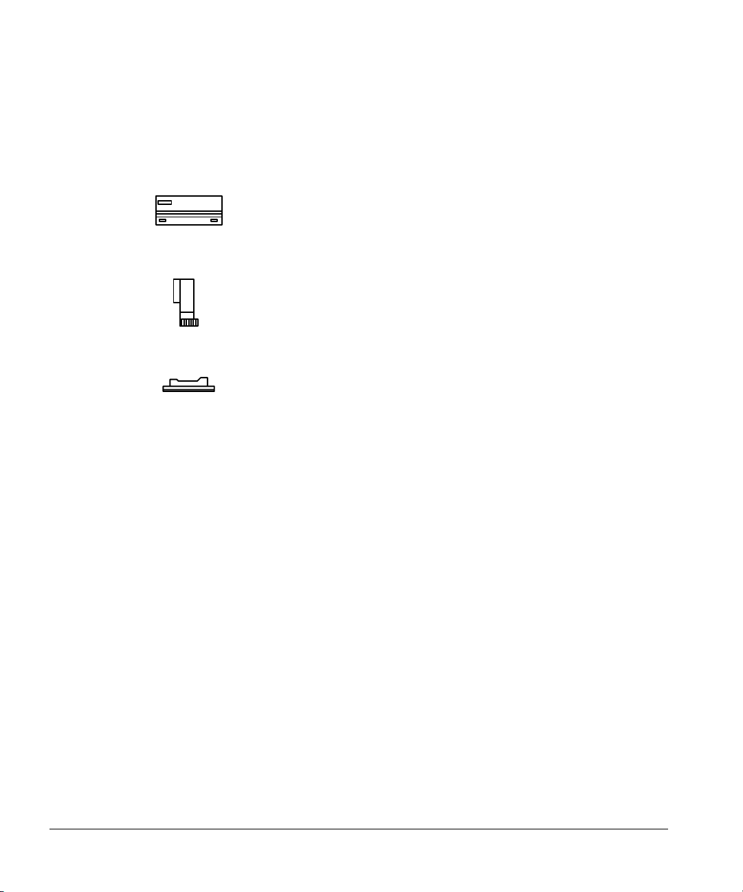
The modules of the automatic liquid sampler
The modules of the automatic liquid sampler
The automatic liquid sampler is made up of three modules:
The G1512A controller and communications module supplies
power and communications to the injector and tray.
The G1513A injector module removes a volume of sample from
a vial and injects it into the inlet.
The 18596C tray module moves sample vials to and from the
injector and the bar code reader.
The automatic liquid sampler works with the PrepStation system to automate
sample preparation procedures. The G1296A/G1926A bar code reader module
is also available. It reads the vial numbers and special instructions for running
a method. It can also be used for agitating the sample vial.
The automatic liquid sampler becomes part of your gas chromatography
system. It introduces sample to an inlet or a column on your GC.
The automatic liquid sampler, with or without the tray, can be controlled by a
variety of integrators and computers, including:
• 6890 Series GC
• Its own electronics (standalone control)
• 3396 integrators plus older models
• Most Agilent laboratory automation systems
• Most Agilent ChemStation systems
• Suitably programmed external computers
3
Page 12
Setting Up
The modules of the automatic liquid sampler
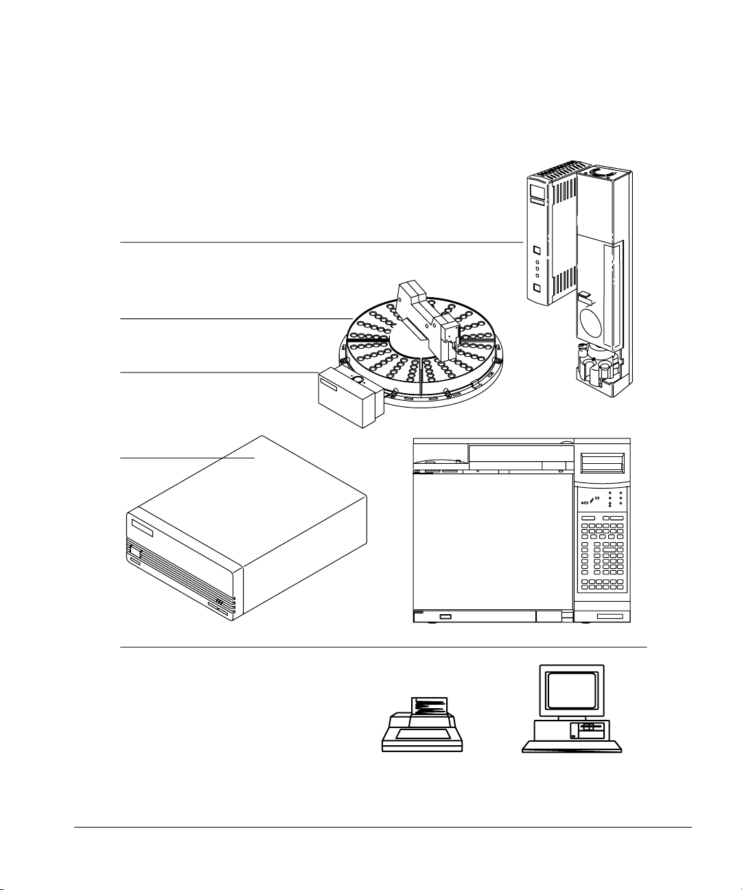
Figure 1 illustrates how the automatic liquid sampler is an integral part of the
analytical system.
One or two injectors
With or without the tray
With or with out the bar
code reader
Controller
Controller configured to communicate with:
• 6890 Series GC
•Integrator
• Personal computer
• Workstation
• Lab data system
• Injector’s control switches
Figure 1. The automatic liquid sampler as part of your analytical system
4
Page 13

Setting Up
Preparing the site
Preparing the site
The automatic liquid sampler has certain environmental, space, and electrical
power requirements.
Environmental considerations
The automatic liquid sampler is designed to operate within ranges of
temperature and relative humidity.
• Temperature range: 0° to 55°C
• Relative humidity range: 5% to 95% at 40°C
• Altitude ranges: up to 2,300 m
Agilent Technologies recommends an environment comfortable for the
operators (reasonably constant temperature and humidity) for optimum
performance and instrument lifetime.
Caution Do not place any instruments that release heat on top of or underneath the
controller. For example, do not place an integrator on top of the controller.
The additional heat can cause damage to its electrical components.
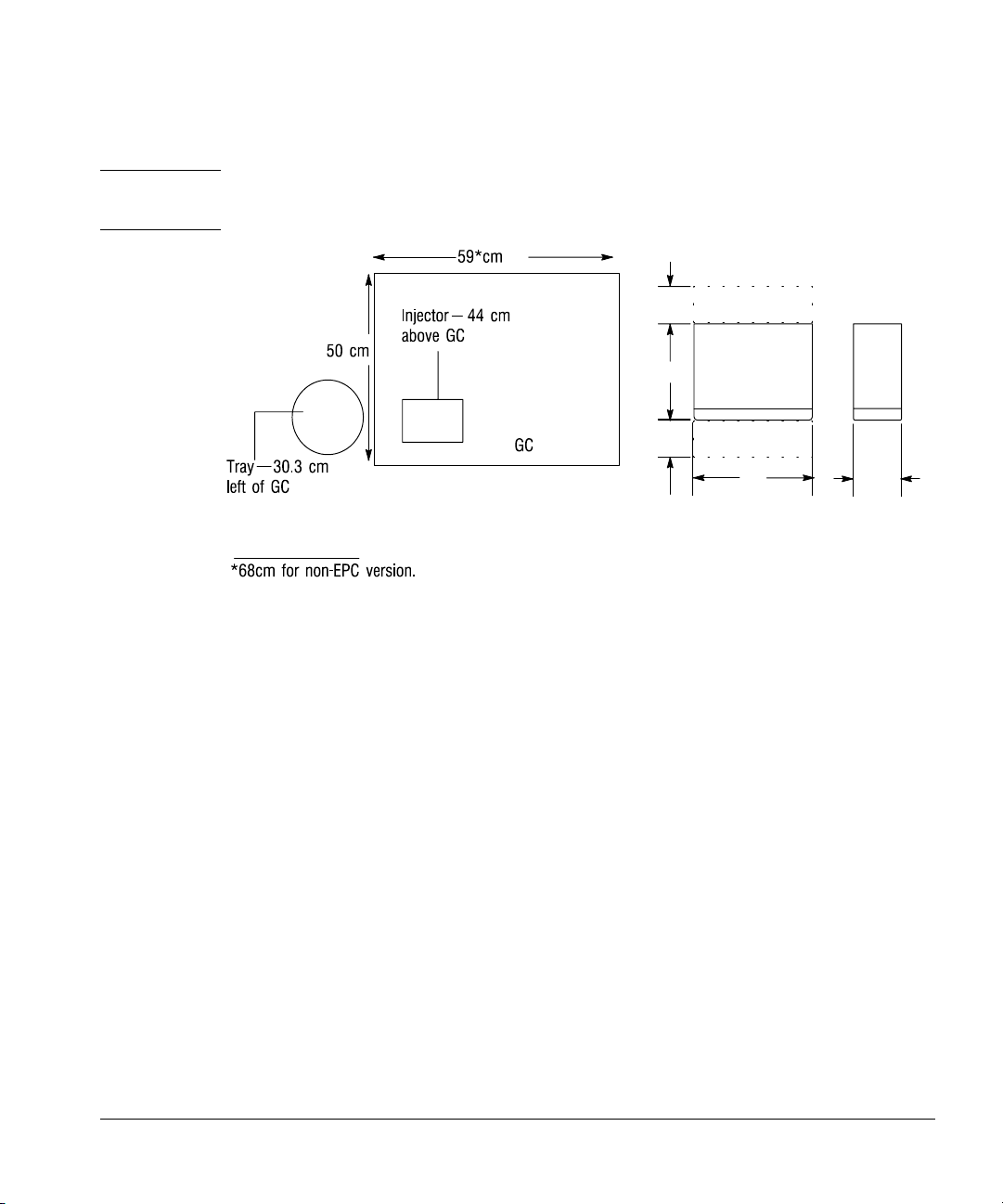
Space considerations
The injector and tray increase the space requirements for the GC. The exact
amount depends on the model of the GC. Figure 2 shows the space
requirements for the components with a 6890 Series GC.
Installed on the 6890 Series GC, the injector adds 44 cm (17 in.) in height. The
tray adds 30.3 cm (9 in.) to the left side and 3 cm (2 in.) to the front. The
controller requires a clear surface about 33 cm (13 in.) wide and 38 cm
(15.2 in.) deep. About 20 cm (8 in.) of the depth is required for cabling. If you
place the controller on its right-hand side (i.e., power switch up), it needs a
clear surface of 38 cm (15.2 in.) deep and 14 cm (6 in.) wide.
5
Page 14
Setting Up
Preparing the site
WARNING Place the G1512A controller where you can easily unplug it from the power
source.
Ventilation and cabling space
10
Top Views
Figure 2. Space considerations
Electrical power requirements
The controller is the power source for the injector and tray. The controller has
an autoranging power supply:
• 100–240 Vac single phase
• 48–66 Hz maximum
•320 VA maximum
The automatic liquid sampler requires a proper earth ground. To protect users,
the metal instrument panels and cabinet are grounded through the threeconductor power line cord in accordance with International Electrotechnical
Commission (IEC) requirements.
30
10
Ventilation space
33
All dimensions in centimeters
or
14
The power cord must be plugged into a receptacle connected to a suitable
earth ground. The receptacle ground should be verified.
6
Page 15

Setting Up
Installing the injectors
WARNING Any interruption of the grounding conductor or disconnection of the power
cord could cause a shock that results in personal injury.
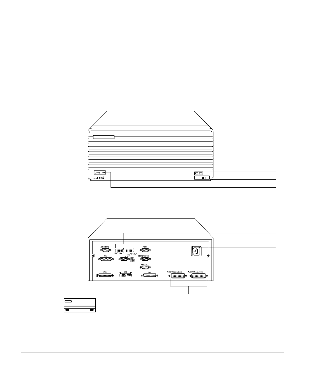
Connecting the controller power cord
1. Check the on/off button on the front of the controller. It must be off or
flush with the front panel before you plug in the power cord. The symbol
“ ” indicates standby. The symbol “|” indicates on.
2. Plug the female end of the power cord into the AC power receptacle on the
back of the controller.
3. Plug the male end of the power cord into the AC power receptacle of your
facility.
Installing the injectors
The injector contains the syringe, a syringe carriage, a six-position standard
turret, a cooling fan that you can turn off, parameter switches, and a last
sample vial switch.
The turret rotates sample vials and solvent and waste bottles into position
under the syringe. Without a tray, you load the sample vials manually into the
turret (maximum of three samples). With a tray, the robotic arm loads the vials
(up to 100 samples). You load the solvent and wash bottles manually (the
quantities of each depend on your controlling device). For more information on
the fan, see “Using the injector fan” on page 34.
7
Page 16
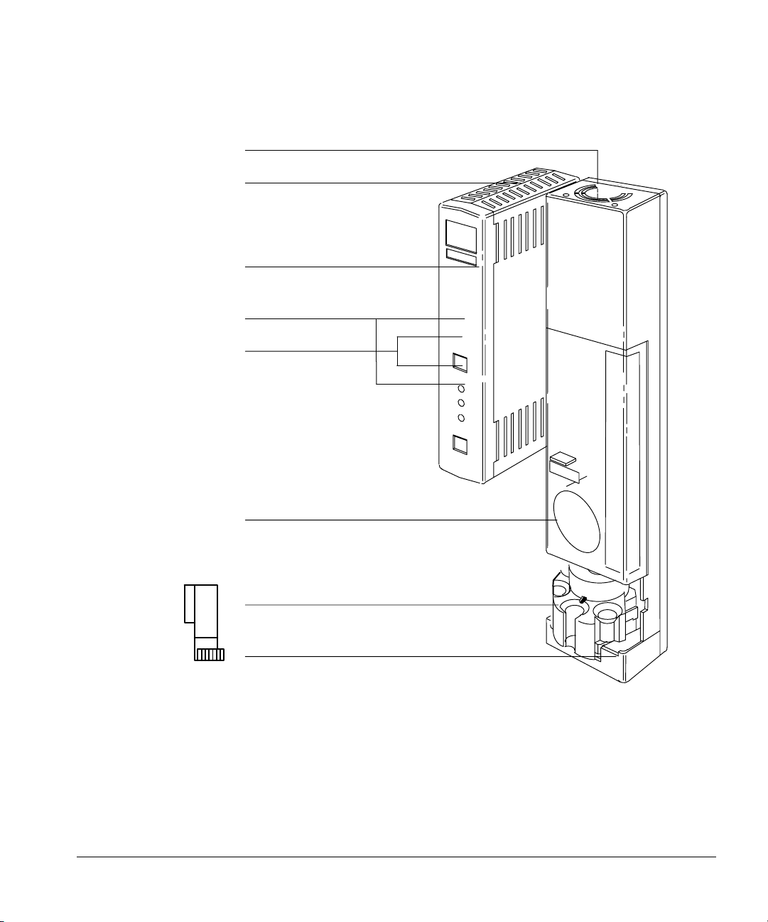
Setting Up
Installing the injectors
Fan
Electronics assembly
Door to control switches
Start/stop buttons
Fault LEDs
Door to syringe
Turret
Base
Figure 3. G1513A injector module
8
Page 17

Setting Up
Installing the injectors
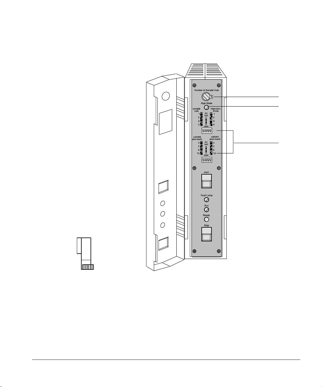
Behind the door to the control switches
There are control switches behind the door on the injector’s front panel.
• You use the rotary switch to set the number of sample vials when no tray is
installed and the remaining ten switches to set six injector parameters
when the system cannot be controlled by the 6890 Series GC, a computer,
or an integrator. For example, you can set the number of injections per
sample vial or the number of syringe washes. For more information, see
“Setting the run parameters” on page 59.
• The injection switch can be used to set fast or slow injection with or
without an integrator or computer controlling the system having any affect
on that setting. However, it will be overridden by settings from the 6890
Series GC and the ChemStation.
• The Align LED is a diagnostic LED to warn users to perform the alignment
procedure. See Chapter 5, Preventive Maintenance and Troubleshooting.
9
Page 18
Setting Up
Installing the injectors
Rotary switch
Align LED
Control switches
10
Figure 4. The parameter control switches
Before you start
To install an injector, you must first:
• Install the tray’s mounting bracket before mounting the injectors (if your
automatic liquid sampler includes a tray). The instructions and hardware
are packaged together with the tray.
• Open the front panel, and remove the foam packing materials.
Page 19
Setting Up
Installing the injectors
• Install the injector mounting posts in the front and back locations of the
injection bracket on the GC.
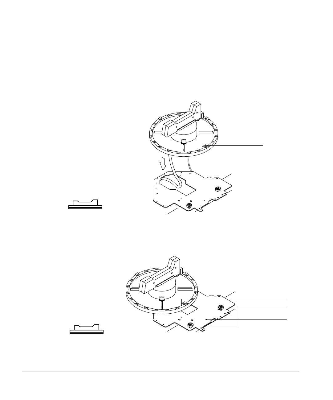
Mounting the injectors
The first part of each step describes how to mount the injector over the front
inlet (injection port).
1. Hold the injector with both hands so the cable points toward you. Line up
the hole in the base of the injector that is nearest the cable with the
mounting post on the bracket. Lower the injector about an inch on to the
post.
Cable
Hole
Front mounting post
Figure 5. Lining up the injector with the mounting post
Door
Turret
Injector base
Mounting pin
Back disk
Front disk
11
Page 20
Setting Up
Installing the injectors
2. Turn the injector so that the turret is facing toward you. Lower the injector
Turret
so that the pin in the base enters the hole in the disk on the mounting
bracket.
Mounting pin
Front mounting post
Disk
Figure 6. Lowering the injector. The injector in this diagram is angled back to illustrate
the position of the mounting pin.
12
Page 21

Setting Up
Installing the tray
Checking your work
❐ Be sure the mounting pin is seated in the hole of the disk. The injector’s feet
should touch the mounting bracket. Be sure the gas lines are not routed
under the feet or the mounting pin.
❐ Turn the turret so you can see the inlet of the GC, and open the door to the
syringe. Be sure the inlet is flush with the surface of the hole in the injector’s
base. This check does not apply to on-column inlets.
❐ If your system does not include a tray, read “Placing sample vials in the
standard injector turret” in chapter 2.
For information on installing syringes, see “Selecting and installing syringes” in
chapter 2. See this section for instructions on how to align the syringe to the
inlet. Alignment is critical when injecting onto a 320- or 250-µm column.
Chapter 6, “Special Topics,” contains more information on use of 320- and
250-µm columns.
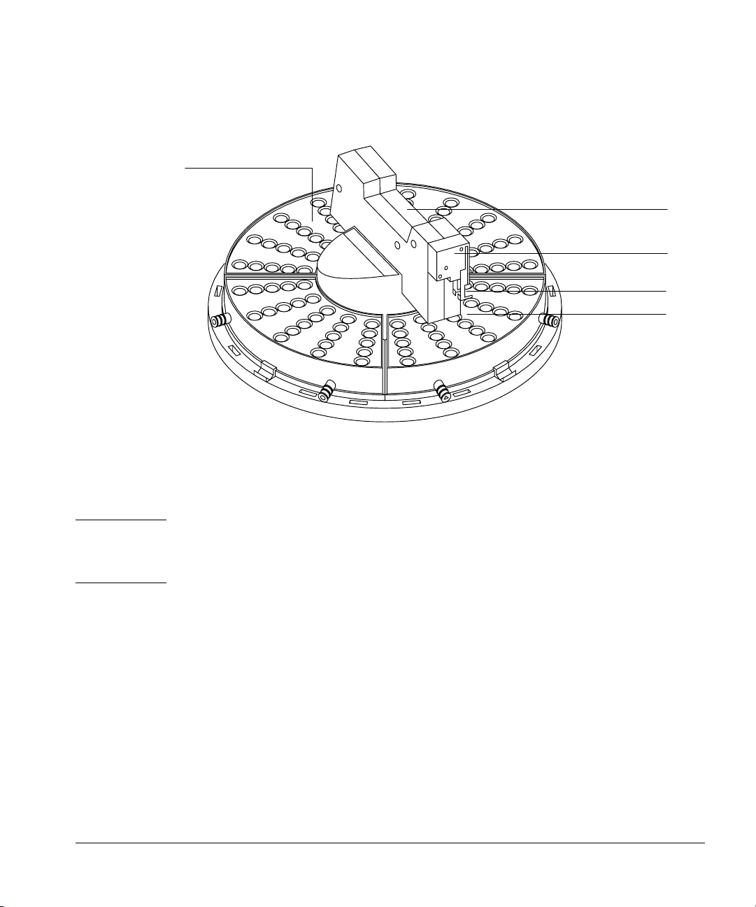
Installing the tray
The tray delivers samples to one or two injectors depending on the
configuration of the gas chromatography system. The arm and gripper
mechanism in the center of the tray loads sample vials into the injector turret
and then returns them to the tray after each injection. It can also transport
sample vials to and from the G1296A/G1926A bar code reader.
Each of the four removable tray quadrants holds 25 vials. Each is hollow and
has fittings so that you can circulate a temperature-controlled fluid through it.
13
Page 22
Setting Up
Installing the tray
Quadrant
Arm
Gripper
Gripper jaws
Sample vial
Figure 7. 18596B tray module
Before you start
Caution Do not remove the tray’s arm back and forth. Do not move the tray’s gripper up
and down. These movements could damage the tray arm. If you need to move
the arm, turn it in a clockwise or counterclockwise direction.
To install a tray, you must first install the tray mounting bracket. The mounting
bracket for the tray attaches to the injector mounting bracket and the GC. The
instructions and hardware are packaged together with the tray.
14
Page 23
Setting Up
Installing the tray
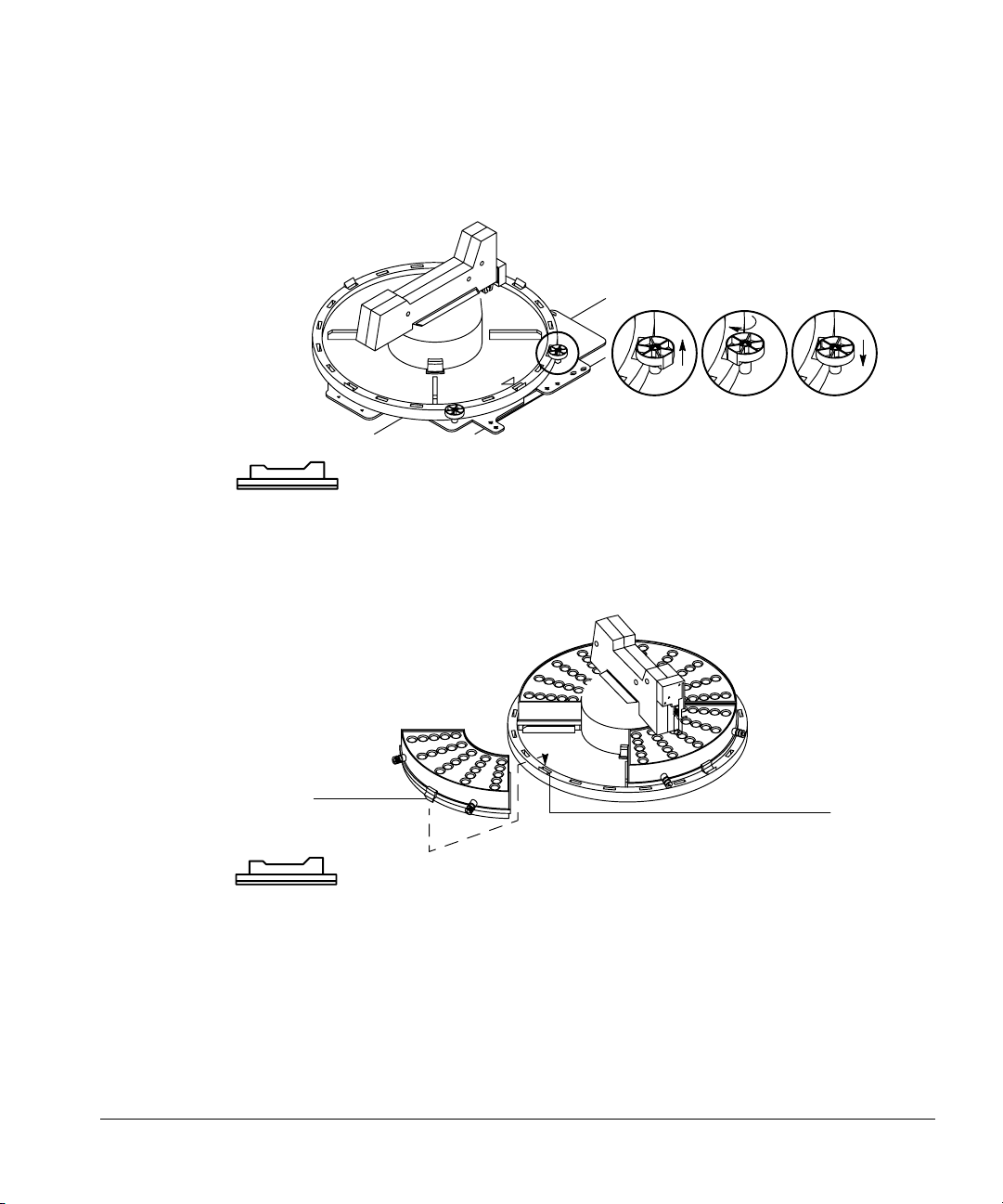
Mounting the tray
1. Thread the cable through the hole in the mounting bracket. Lower the tray
onto the bracket. Position the tray so that it sits flat on the bracket with
the raised arrow pointing toward the right (the front injector). Move the
injector cable out of the way.
Arrow
Figure 8. Threading the tray cable
2. Line up the arrow on the tray base with the alignment pin on the mounting
bracket. Slide the tray to the right until the edge is under the two tray
locks.
Arrow
Tray locks
Alignment pin
Figure 9. Attaching the tray
15
Page 24
Setting Up
Installing the tray
3. Lock the tray into place by pulling each lock up (A), turning each lock (B),
and inserting each tab into a slot in the tray (C).
A B C
Figure 10. Locking the tray
4. Snap the tab of each tray quadrant into a slot on the base of the tray. The
numbers on the quadrants should match the numbers on the base.
16
Ta b
Slot
Figure 11. Inserting the tray quadrants
Checking your work
❐ Be sure the tray base is all the way to the right and locked into place.
❐ Be sure the quadrants are seated on the tray base.
Page 25
Setting Up
Installing the controller
Installing the controller
The G1512A controller provides power and the communication interface for
18593A/B or G1513A injectors and for the 18596A or 18596B/C tray.
There are 11 connectors and two sets of switches for defining the
communication type.
Fault LED
Serial number
On/off button
Injector connectors
Figure 12. G1512A controller and communications module
Configuration switches
AC power receptacle
17
Page 26
Setting Up
Installing the controller
This section covers connecting the injector and tray cables to the controller,
connecting the controller to the GC, connecting the controller to the data
handling device, and plugging in the controller.
Find the power cord in the controller box. Check the shape of the plug and the
source voltage listed on the packing contents sheet. Verify that the power cord
is appropriate for the power source at your facility.
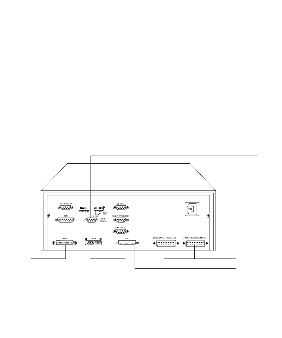
Connecting cables to other instruments
The automatic liquid sampler communicates to other instruments via cables
that connect to the various connectors on the controller. Figure 13 shows the
connectors on the back of the controller and what they are used for.
RS-232-C to computer
Connect to a
computer
Connect to the
Instrument
Network
Figure 13. Common cable connections
18
Connect to the
bar code reader
Connect to the injector modules
Connect to the tray module
Page 27

Setting Up
Installing the controller
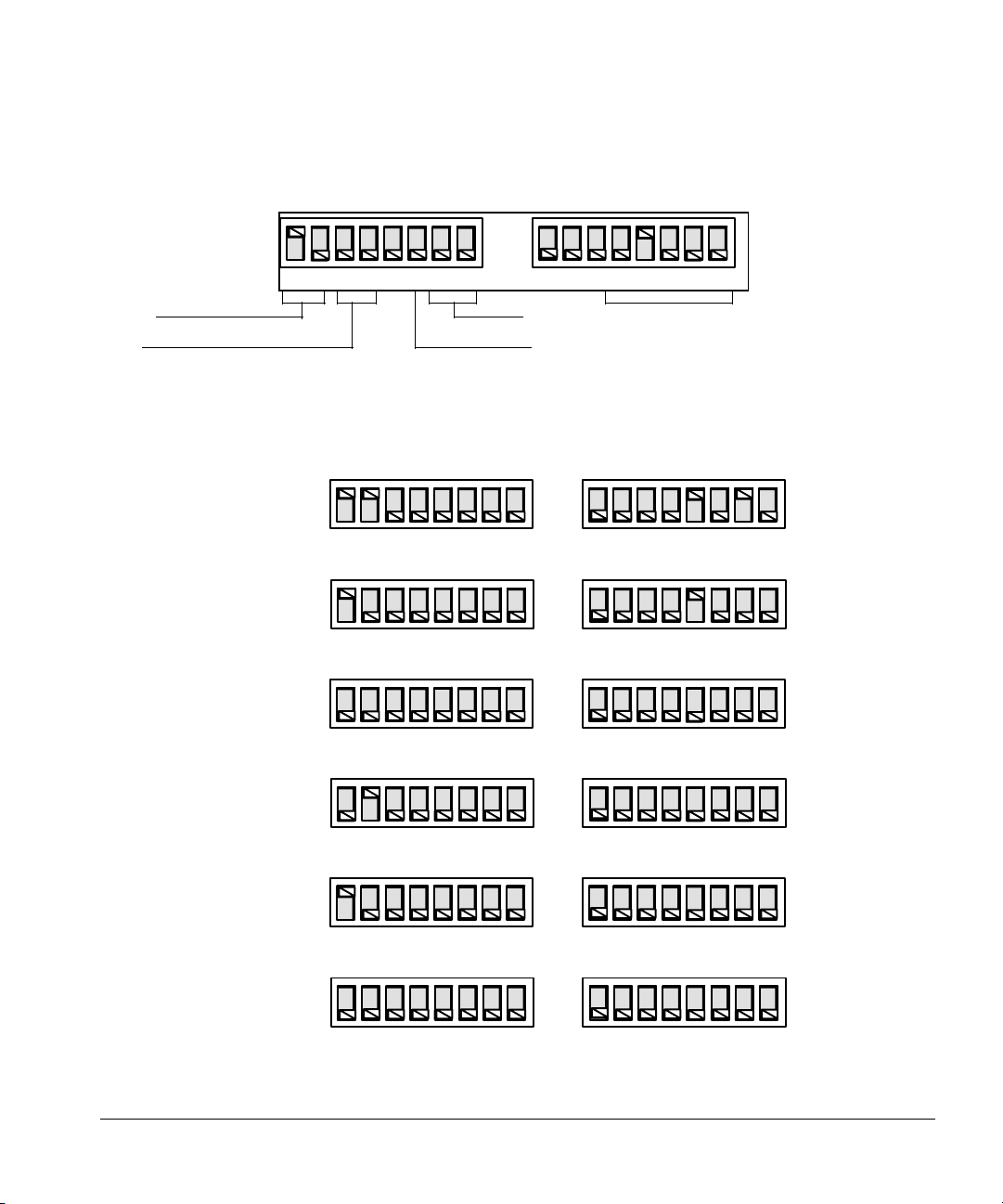
Setting the configuration switches
There are 16 switches on the back of the controller. Figure 14 and Figure 15
show the switches and settings for five common types of communications.
When you are using ChemStation software, you must set the GPIB address
switches to a unique address. The address for the first sampler is usually set to
“8.” For a complete list of address switches, see Table 3.
Configuration switch definitions
The following tables describe the configuration switches and their settings.
Table 1. Left-hand Switch Settings
Switch Description Possible Values
MM Communication mode type 00—INET, standalone
10—3365 ChemStation, MS ChemStation
(Rev 3.65 and lower)
11—ChemStation, MS ChemStation
(Rev 3.71 and higher)
01—Asynchronous standalone
PP The bar code reader position 00—Front
01—Back
10—Right
11—Left
H RS-232-C host handshake 0—XON/XOFF
1—RTS/CTS
BB RS-232-C host baud rate 00—2400
01—9600
10—19.2 K
11—38.4 K
Table 2. Right-hand Switch Settings
Switch Description Possible Values
LF Controller termination
message
16,8,4,2,1 GPIB address of controller 00000=0, 00001=1, 00010=2, 00011=3, etc.
0—Line feed only
1—Carriage return and line feed
(see Figure 14)
19
Page 28
Setting Up
Installing the controller
Communication mode Baud rate
Bar code reader position Handshake
Figure 14. Setting the address switches
ChemStation
6890 Series GC
MSD ChemStation
(rev 3.70 and above)
3365 ChemStation
MSD ChemStation
(rev 3.65 and below)
HP-UX ChemStations
Integrator with INET
Synchronous standalone
1
0
LFBBHPPMM124816
1
0
LFBBHPPMM124816
1
0
LFBBHPPMM124816
1
0
LFBBHPPMM124816
GPIB address
1
0
1
Address = 10
0
1
Address = 8
0
1
0
Asynchronous standalone
35900 Loop
RS-232-C, described in
serial interface manual,
part no. 18594-90300
Figure 15. Examples of switch settings
20
1
0
1
0
1
0
1
0
LFBBHPPMM124816
1
0
LFBBHPPMM124816
1
0
LFBBHPPMM124816
Page 29

Table 3. Possible GPIB Address Switch Settings
Setting Up
Installing the controller
Switch
GPIB Address
0 00000 15 01111
1 00001 16 10000
2 00010 17 10001
3 00011 18 10010
4 00100 19 10011
5 00101 20 10100
6 00110 21 10101
7 00111 22 10110
8 01000 23 10111
9 01001 24 11000
10 01010 25 11001
11 01011 26 11010
12 01100 27 11011
13 01101 28 11100
14 01110 29 11101
Settings GPIB Address
Switch
Settings
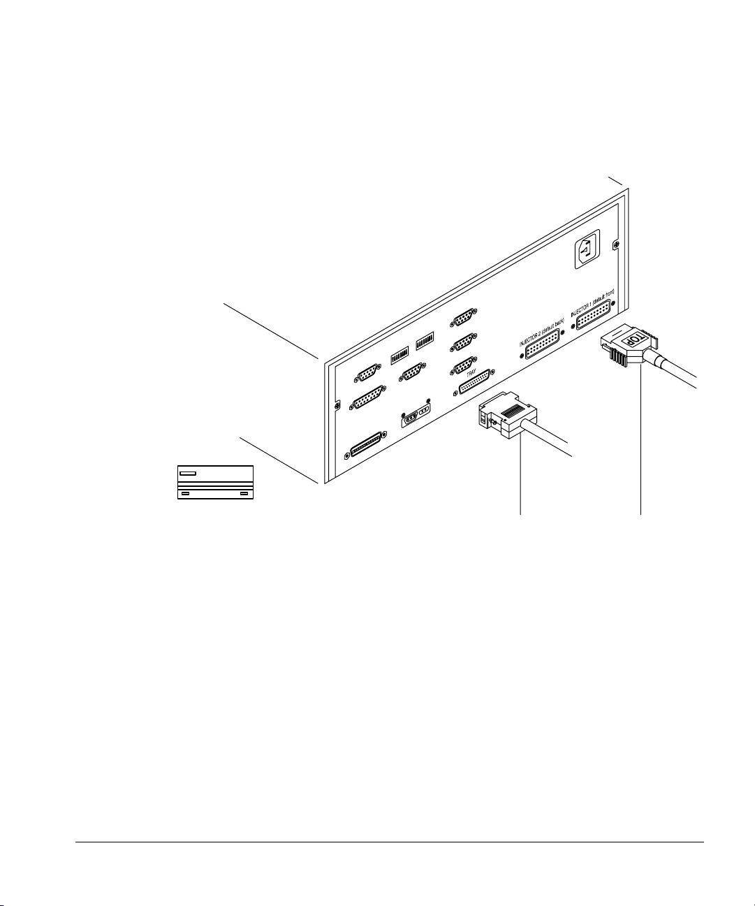
Connecting the injector cables
With the power off, plug each injector cable into the connector on the back
panel of the controller associated with the position of the injector, front or
21
Page 30
Setting Up
Installing the controller
back. Be sure the spring clamps on either side of the plug snap onto the
connector. Note the TOP label on the connector for orientation purposes.
22
Tray Injector
Figure 16. Connecting the injector and tray cables
Connecting the tray cable
Plug the cable into the tray connector on the back panel of the controller.
Secure the plug to the connector with a small flathead screwdriver.
Connecting the controller power cord
1. Check the on/off button on the front of the controller. It must be off or
flush with the front panel before you plug in the power cord.
2. Plug the female end of the power cord into the AC power receptacle on the
back of the controller.
3. Plug the male end of the power cord into the AC power receptacle of
your facility.
Page 31

Setting Up
Installing the controller
Checking your work
❐ Be sure the injector and tray plugs are fastened securely.
❐ Be sure all the communication cables are installed and fastened
securely.
❐ Be sure any external control or data handling devices are configured
correctly by referring to the appropriate manual.
❐ Turn the controller on. Listen for a single beep. This means the system
initialized correctly.
• On the injector, the red, yellow, and green lights flash on together.
The red and yellow lights go off. The green light stays on. If the red
light stays on, be sure the injector is mounted correctly and the door
to the syringe chamber is closed.
• On the controller, the yellow and green lights flash on together. The
green light stays on while the yellow light goes off.
To test the operation of the automatic liquid sampler, turn to chapter 2,
“Preparing for Operation.”
23
Page 32

6890A GC
this page is from
"Agilent 7683B Automatic Liquid Sampler
Installation, Operation and Maintenance"
Installation 2
Follow the instructions below to properly wire the G2912A controller. See
“Procedure 8. Install the G2912A ALS Controller” on page 55 for installation
instructions for the G2912A controller including the power supply cord.
G2912A Controller
Front
Injector
Back
Injector
Tr ay
5890
Remote
6890
Remote
RS-232
Inj1 Inj2
Front
Power cords not shown
Back
Injectors
G2614-60610
Tr ay
Bar Code
Reader
G1530-60930
G1530-60600
Sampler
6890A GC
Remote
Figure 18 Cables for 6890A GC
1 Connect the injector(s) to the controller.
2 Connect the tray to the controller with G2614-60610 cable.
3 Connect the controller to the GC with a G1530-60930 cable and a
G1530-60600 cable.
4 Connect the Bar Code Reader to the tray, if desired.
5 Connect the power cords.
Installation, Operation, and Maintenance 47
Part 1, Installation
Page 33

Setting Up
Installing the controller
24
Page 34

2
Preparing for Operation
Page 35

Preparing for Operation
This chapter contains detailed information for preparing the automatic liquid
sampler for operation, including:
• Preparing sample vials
• Using the injector fan
• Preparing the solvent and waste bottles
• Selecting and installing syringes
• Maintaining the inlet
• Adapting for cool on-column injection
To optimize your sampler operation, it is important to have thorough
preparation of your samples, sample vials, syringes, and inlets. Regular
maintenance also keeps your equipment and analysis running smoothly. For
more information, see chapter 5, “Preventive Maintenance and
Troubleshooting.”
Preparing sample vials
26
This section explains how to select, label, fill, cap, and place the sample vials.
Selecting and labeling sample vials
The injector and the tray use glass sample vials and crimp caps or Target® DP
screw-cap vials that meet a set of specifications. These are available with a
write-on spot for easy labeling. If you choose to make your own labels, read the
following specifications for location and thickness of labels.
™
Page 36

Preparing for Operation
Preparing sample vials
The location and thickness of a vial label can affect the delivery of the bottles
to and from the injector. Agilent Technologies recommends the position and
maximum label thickness shown in the following diagram.
No label
5.6 0.6
20.5 1.0
No label
All measurements in millimeters
.2
.44
Figure 17. Label specifications
Caution The correct sample vial dimensions are critical for proper operation. Vials that
do not meet specifications may cause sampler errors. Service calls and repairs
found to be due to vials and microvials that do not meet these specifications
are not covered under warranty or the service contract.
Specifications
Figure 18 illustrates most of the critical dimensions for the sample vials and
microvial inserts. These dimensions do not make up a complete set of
27
Page 37

Preparing for Operation
Preparing sample vials
specifications. Some of the dimensions are too difficult to measure without
special instruments.
Microvial insert
5 minimum
All dimensions in millimeters
Crimp cap sample vial
3.5
28.4
Figure 18. Dimensions for sample vials and microvial inserts
Sample caps and septum
Although septa come in different colors, the characteristics are measured by
inertness and type of composition. There are two basic types of septa used
with both crimp caps and screw-on caps. Each has different resealing
characteristics and a different resistance to interaction with solvents.
8.2 maximum
11.7 0.2
3.7
28
• A general-purpose rubber formulation made from natural rubber is coated
with Teflon on the sample side. It has a pH range of 4.0–7.5. It is least
resistant to solvents after puncture, however, it is more easily cored. This
coring may place septum pieces in the solvent that affect your
chromatograms.
• A high-quality, low-extractable silicone rubber, coated with Teflon on one
or both sides, is somewhat resistant to solvents after puncture.
Refer to your Agilent analytical supplies catalog for more information.
Page 38

Preparing for Operation
34.5 mm
Preparing sample vials
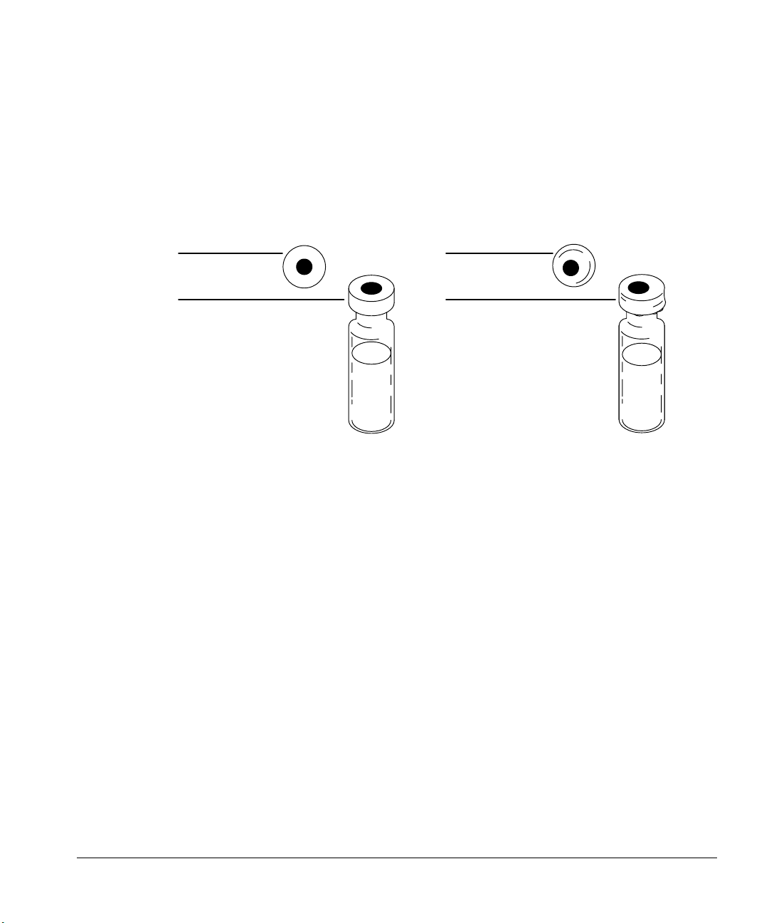
Figure 19 illustrates the recommended and minimum diameter for vial cap
apertures.
5.58 (0.220 in.) recommended
4.65 (0.183 in.) minimum
All dimensions in millimeters
Figure 19. Specifications of vial cap aperture
Use amber glass vials for light-sensitive samples.
The last specification to consider is the total height of the capped vial.
Figure 20 illustrates the recommended maximum height of a crimp capped or
screw capped vial.
Figure 20. Maximum height of a vial with cap
Filling sample vials
Follow these recommendations to obtain reliable, high performance with the
sampler and prevent contamination or injection volume problems.
Recommended volumes for a maximum of five injections per vial are:
• 1 ml for the 2-ml vial
• 50 µl for the 100-µl vial
29
Page 39

Preparing for Operation
Preparing sample vials
For large volumes and multiple injections, you will have to decide how to
divide the sample among several vials to obtain reliable results. You have to be
aware when sample volume is low. For example, if the vials are less than half
full, contaminants from the previous sample injection or solvent washes may
affect the sample. Due to the various parameter settings available, the many
suppliers of consumables, and the choices of vials, microvials, vial caps, and
septa, some method development will need to be done to optimize your
analysis.
1 ml
3.6 mm*
2-ml vial
*Needle position based on standard sampling depth. See chapter 3 for more information on setting parameters
for sampling depth.
50 ml
100-ml vial
Figure 21. Recommended volumes for sample vials
Caution If the vials are more than half full, a vacuum may interfere with the syringe
delivering a precise volume.
Do not inject air into the vial to compensate for the vacuum. Injecting air into
the vial often damages the cap septum so that it is no longer airtight.
Crimp capping sample vials
Use a crimper to put on the airtight crimp caps.
1. Clean off the inside surfaces of the crimper jaws.
2. Place the crimp cap over the top of the vial.
30
Page 40

Preparing for Operation
Preparing sample vials
3. Lift the vial into the crimper, and squeeze the handle until the bottom grip
reaches the adjuster screw.
Handle
Adjuster screw
Jaws
Crimp cap
Sample vial
Figure 22. Crimping caps
Caution Vials that do not have properly crimped caps may cause sampler errors.
When a tray is not installed, you may be able to use sample vials with no caps,
snap-on caps, or screw-on caps depending on your application. If a tray is
installed, sample vials must have crimp caps or Target
Check that your vial is crimped as follows:
1. Cap has no metal folds or wrinkles on the part of the cap that wraps under
the neck of the vial.
• If there are folds or wrinkles, flatten any wrinkles by turning the vial
about 10° and crimping it again. Adjust the crimper for a looser crimp
by turning the adjusting screw clockwise.
2. Cap is too tight to turn by hand.
• If the cap is loose, adjust the crimper for a tighter crimp by turning the
adjusting screw counterclockwise. Crimp the cap again.
®
DP™ screw-cap vials.
31
Page 41
Preparing for Operation
Preparing sample vials
3. Cap has a flat septum centered over the top of the vial.
• If the septum is not flat, remove the cap, turn the adjusting screw
clockwise, and try again.
• If the cap is not centered, remove the cap, and make sure the new cap
is flat on the top of the vial before you squeeze the crimper.
Centered
No folds or wrinkles
Off center
Folds and wrinkles
Figure 23. Acceptable and unacceptable caps
There are three reasons for crimping the cap properly:
• The syringe tends to core a curved vial septum and drop small pieces of
the material into the sample.
• The syringe needle could hit the metal part of the uncentered cap.
• The tray gripper may drop a vial if the cap has folds or wrinkles in it.
Placing sample vials in the standard injector turret
If you do not use the tray, you can place one, two, or three vials in the injector
turret. For two or three sample vials, you must convert some of the bottle
positions to sample vial positions with sample inserts.
32
1. Place the appropriate sample inserts in bottle positions 2 and 3 on the
turret.
• For one sample, no inserts are needed. Position one is molded into the
turret.
Page 42

2. Place the sample vials into the sample inserts.
Preparing for Operation
Preparing sample vials
White sample insert
for sample 3
Turret
White sample insert
for sample 2
Sample 1
Figure 24. Placing sample inserts for three sample vials
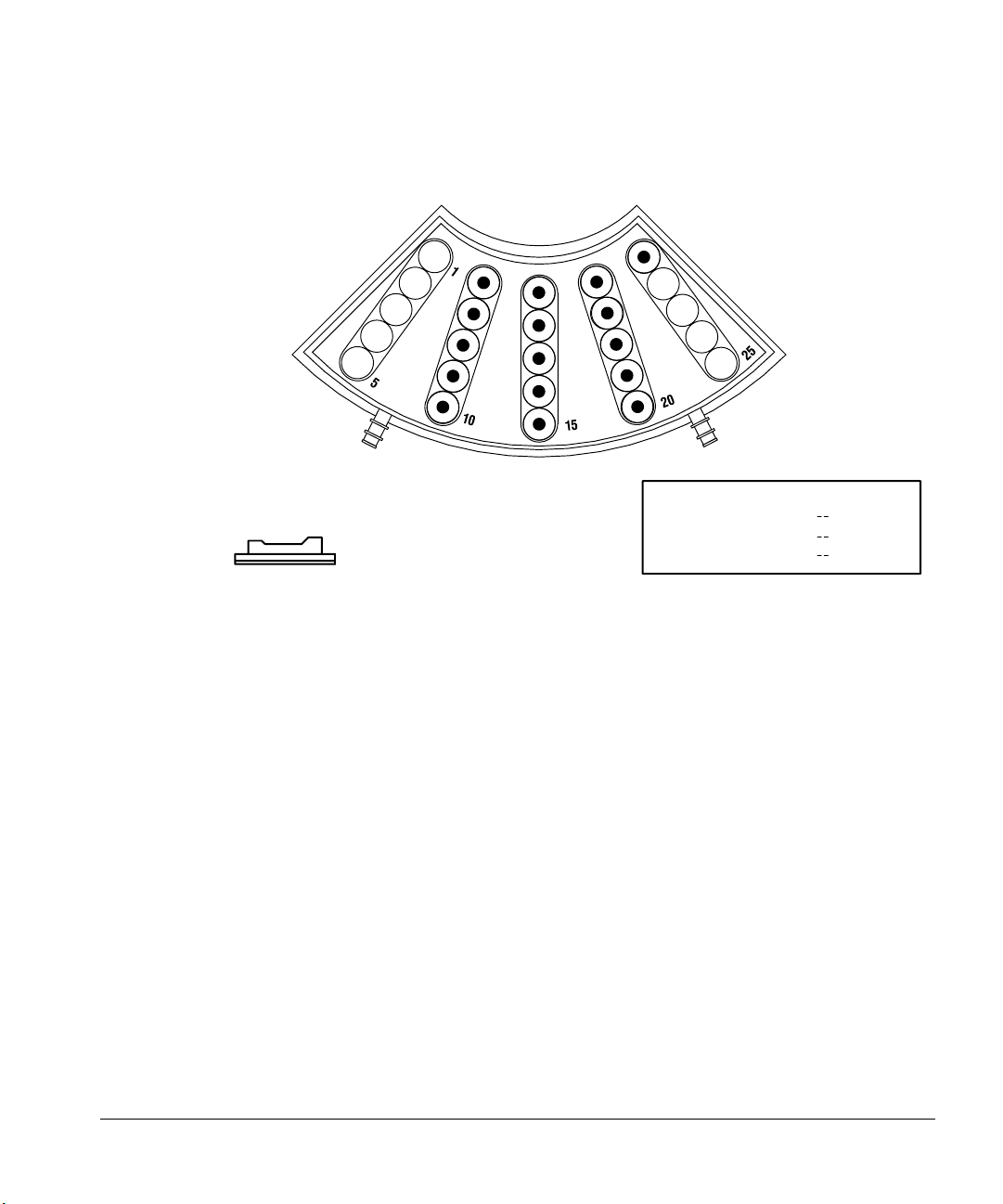
Placing sample vials in a tray
You can place up to 100 samples in the tray’s four quadrants. The tray gripper
picks up the vials and delivers them to the sample vial position in the turret.
When you are not using the external control instruments, place the first bottle
in quadrant position 1. The tray continues to deliver vials until it delivers the
last one in the series or until it encounters an empty position. For more
information, see chapter 4, “Standalone Control.”
When you are using another instrument such as an integrator or ChemStation
to control the tray, the first and last bottle positions are defined when you set
the sequence parameters. The tray begins picking up sample vials at the
position that corresponds to the “first bottle” and stops after it replaces the vial
that corresponds to the “last bottle.”
33
Page 43
Preparing for Operation
Using the injector fan
For more information, see “Setting the run parameters” in chapter 3.
Figure 25. Specifying tray positions with a 3396 integrator and 5890 or 6890 GC
FRONT INJECTOR
INJ/BOTTLE
FIRST BOTTLE
LAST BOTTLE
1 >
1 >
5 >
@
6
21
34
Using the injector fan
The purpose of the fan is to push cool air over the samples and solvent to keep
them cooler. Also, some samples may boil out of the syringe if heat builds up in
the injector.
For a particular application, you may want the area around the samples to be
warm. Heat can help the delivery of viscous, high-boiling samples.
The default position of the fan is on. If your analysis requires the fan to be off,
use the instructions “Turning the fan off” below.
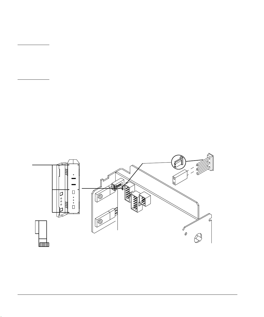
Turning the fan off
To turn the fan off, follow these steps.
1. Turn the controller power switch off.
2. Put on a grounded wrist strap.
Page 44
Preparing for Operation
Using the injector fan
Caution This procedure requires protection against electrostatic discharge. Use a static
control wrist strap connected to a ground (part no. 9300-0969 for large wrists
or part no. 9300-0970 for small wrists). If you do not use static protection, you
may damage the electronics of the injector. Do not touch any of the electrical
components, especially the microprocessor.
3. Open the door to the injector electronics assembly, and remove the three
screws on the left edge of the panel with a No. 1 Point Pozidrive
screwdriver.
4. Open the left-hand side of the assembly. Remove the blue ribbon cable
(P3) so P6 is more visible. Locate the P6 jumper switch on the top left
front corner of the printed circuit board.
5. Connect the P6 jumper so that it covers the top two prongs on the circuit
board labeled OFF. See Figure 26. Return the ribbon cable to its original
position.
OFF
Screws
P6
Figure 26. P6 jumper setting
6. Close the left-hand side of the assembly, and replace the three screws on
the left edge of the front panel.
ON
35
Page 45

Preparing for Operation
Preparing the solvent and waste bottles
7. Restore the power. The fan should now be off. If it is still running, reopen
the injector, and check the position of the P6 jumper according to the
instructions in step 5.
Preparing the solvent and waste bottles
The solvent bottles hold solvent for rinsing the syringe between injections. The
injector dispenses the solvent washes and sample washes into waste bottles.
The first two parts of this section explain how to select, fill, and place the
solvent and waste bottles. The last two parts of this section explain how to
estimate the maximum number of vials you can run at one time and how the
injector controls carryover.
For information on how to set the number of washes, see “Setting the run
parameters” in chapter 3.
36
Selecting the bottles
The injector uses 4-ml bottles with diffusion caps to hold the solvent and
waste. You can use diffusion caps or septa on these bottles to reduce
evaporation and diffusion of your solvents and waste. Agilent Technologies
recommends diffusion caps over septa for two reasons:
• The diffusion cap allows multiple entrances into a bottle without
contaminating the liquid inside the bottle with small pieces of septum
material.
Page 46

Preparing for Operation
Preparing the solvent and waste bottles
• For many common solvents, the rate of diffusion out of the bottle is less
with a diffusion cap than with a septum that has been punctured with a
standard syringe needle.
Diffusion cap
Agilent Technologies recommends
using a diffusion cap instead of a
septum to reduce solvent
contamination and evaporation.
Figure 27. 4-ml bottle used for solvent and waste
Filling and placing the bottles
Before each sequence or group of sequences, prepare your solvent and waste
bottles by doing the following:
1. Rinse and fill each solvent bottle with 4 to 4.5 ml of fresh solvent. The
liquid level should be near the shoulder of the bottle. If the solvent bottle is
filled with 4.5 ml of solvent, the syringe can reach about 2 ml or about 250
washes for a 10-µl syringe.
4.5 ml maximum
2.5 ml minimum
18.5 mm
Figure 28. Shows position of the syringe tip when withdrawing solvent
37
Page 47

Preparing for Operation
Preparing the solvent and waste bottles
2. Empty and rinse each waste bottle. The syringe can dispense about 4 ml of
waste into the waste bottle or about 500 washes for a 10-µl syringe.
4 ml maximum
Figure 29. Shows position of syringe tip when dispensing waste
3. Place the bottles in the appropriate positions on the injector turret
according to the table on page 40. The positions are labeled on the turret,
Solvent A, Waste A, Solvent B, and Waste B.
Caution Do not refill a solvent bottle that still has solvent left in the bottle. The solvent
from the last analysis may be contaminated.
38
Figure 30 shows an example of the turret positions used with and without a
tray.
• If a tray is installed, place four bottles in turret positions solvent A, waste
A, solvent B, and waste B.
Page 48

Preparing for Operation
Preparing the solvent and waste bottles
• If a tray is not installed, place two or three bottles (solvent A, waste A, and
solvent B) in the turret positions. Position 3 in the turret can be used as
sample 3 or solvent B. Make sure you have the correct vial in the turret.
Top view with a tray Top view without a tray
Solvent A Solvent A
Waste B
Solvent B
Waste A Waste A
Figure 30. Examples with and without a tray
Solvent B
39
Page 49

Preparing for Operation
Preparing the solvent and waste bottles
Caution When a tray is installed, place a waste bottle in both waste position A and
waste position B. The injector alternates dispensing waste between the two
positions. With the 6890 Series GC, you can choose A, B, or both.
System Solvent Waste
Standalone With a tray
Without a tray
3365/5890 With a tray
Without a tray
3366/5890 With a tray
Without a tray
3396/6890 With a tray
Without a tray
Multitechnique
ChemStation/5890
Multitechnique
ChemStation/6890
With a tray
Without a tray
With a tray
Without a tray
A & B
A
A, B, or both
A, B, or both
A, B, or both
A
A, B, or both
A, B, or both
A, B, or both
A, B, or both
A, B, or both
A, B, or both
A & B
A
A & B
A
A & B
A
A, B or both
A
A & B
A
A, B or both
A
Do you need to read further?
The volumes of the solvent and waste bottles determine the number of sample
vials that you can run at one time. If your application requires more than the
maximum number of washes listed in Figure 31, you must read the next section
entitled, “Estimating the maximum number of sample vials.” The total number
of washes includes all solvent (pre- and post-injection) and sample washes
using the default needle depth. This is critical to your solvent supply if solvent
prewashes are not part of your solvent needed estimation.
40
Page 50

Preparing for Operation
Preparing the solvent and waste bottles
Number of Bottles Solvent Limit Waste Limit
Syringe size 5 µl 10 µl 5 µl 10 µl
Two bottles 1,000 500 2,000 1,000
One bottle 500 250 1,000 500
Note: Wash volume is 0.8 times the syringe volume.
Figure 31. The maximum number of washes (pre- and post-injection)
Caution Do not exceed the solvent and waste limits of the bottles. If you exceed these
limits, sample carryover may affect your analysis.
Example 1 (tray not installed): Your application requires 10 sample
washes and 10 solvent washes with a 10-µl syringe. For three sample vials (five
injections per vial), you need 150 solvent washes, and you need to dispense 300
syringe volumes of waste. With this example, you are limited to one bottle for
solvent and one bottle for waste.
Figure 31 shows that you can have up to 250 washes from one solvent bottle
and can dispense up to 500 washes into the waste bottle. You are within the
limits and do not have to read any further.
Example 2 (tray installed): Your application requires three sample washes
and three solvent washes with a 10-µl syringe. For 40 sample vials (two
injections per vial), you need 240 solvent washes, and you need to dispense 480
syringe volumes of waste. With this example, you are using two bottles for
solvent and two bottles for waste.
Figure 31 shows that you can have up to 250 washes from each solvent bottle
and can dispense up to 1,000 washes into the waste bottles. You are within the
limits and do not have to read any further.
Example 2b (tray installed): Your application requires three sample washes
and three solvent washes with a 10-µl syringe. If you had 60 samples, you
would need 360 washes from the solvent bottles. You would have to place
41
Page 51

Preparing for Operation
Preparing the solvent and waste bottles
solvent bottles in both positions and set the run parameters for solvent washes
from both positions (e.g., one from solvent A and two from solvent B).
Example 3 (tray installed): Your application requires three sample washes,
three solvent A washes, and three solvent B washes with a 10-µl syringe. For
100 sample vials (two injections per vial), you need 600 solvent washes and
need to dispense 1,200 syringe volumes of waste. With this example, you are
using two bottles for solvent and two bottles for waste.
Figure 31 shows that you can have up to 250 washes from each solvent bottle
and can dispense up to 1,000 washes into the waste bottles. You would exceed
the solvent and waste capacity of the bottles. Read the next section to estimate
the maximum number of sample vials you can run at one time.
Estimating the maximum number of sample vials
This section contains equations and tables for estimating the maximum
number of sample vials you can run before you must replace the solvent or
empty the waste bottles.
Caution The number of sample vials given in the equations and tables are estimates.
Characteristics of the solvent, such as the evaporation rate and surface
tension, may affect the capacity of the bottles.
If you use either the tables or the equations, you must know the following
parameters for your application:
• The number of injections per vial.
• The number of solvent washes per pre- and post-injection required from
each solvent bottle.
• The number of sample wastes and solvent washes per injection that the
injector dispenses into each waste bottle. When the tray is installed, you
must use two waste bottles. The injector dispenses the waste equally
between the two bottles unless you have specified differently on the
6890 Series GC.
• The syringe size, 5 µl or 10 µl.
42
Page 52

Preparing for Operation
Preparing the solvent and waste bottles
Using the equation to estimate
1. Substitute the parameters of your application into both equations.
• If you are using a 5-µl syringe, substitute 0.004 ml/wash for the
0.008 ml/wash in each equation.
• If a tray is installed or both waste bottles are being used, substitute
8.0 ml of waste for the 4.0 ml of waste in the second equation.
2. Calculate the answers for both equations. Use the smaller of the two
answers for the estimate.
• Equation S estimates the maximum number of vials from the volume
of solvent available from the bottle associated with the largest
number of washes.
Equation S
Maximum
Number
of Vials
=
0.008 ml/wash Number
××
2.0 ml of solvent
injections/vial
Largest number solvent
washes from a bottle
• Equation W estimates the maximum number of vials from the waste
bottle capacity.
Equation W
Maximum
Number
of Vials
=
0.008 ml/wash Number
××
4.0 ml of waste
injections/vial
Number solvent and
sample washes/injection
Equation method example
Assume a tray is installed and your application parameters are:
• Two injections per vial
• Three washes from solvent bottle A
• Two washes from solvent bottle B
• Two sample washes
• 10-µl syringe
43
Page 53

Preparing for Operation
Preparing the solvent and waste bottles
1. Substitute the parameters of your application into equations S and W.
S: Maximum number of vials = 2.0 ( 0.008 x 2 x 3 ) = 41
W: Maximum number of vials = 8.0 ( 0.008 x 2 x 7 ) = 71
2. Calculate the answers for both equations. Use the smaller of the two
answers, answer (41).
Using the table to estimate
1. Go to the S table in Figure 32. In the left-hand column, find the largest
number of solvent washes you need from a solvent bottle. If you use a tray,
you can divide the solvent washes between both waste bottles.
2. Read across this row to the column with the number of injections you are
taking from each vial. The intersection of row and column is the maximum
number of vials that you can run from the limiting bottle.
• When you are using a 5-µl syringe, multiply the maximum number of
vials listed in the figure by 2.
44
Page 54

Preparing for Operation
Preparing the solvent and waste bottles
S
Number
of
solvent
washes
per
injection
123456
1 100+100+83625041
2 100+6241312520
3 834127201613
4 623120151210
5 50251612108
6 412013108 6
7 3517118 7 5
8 3115107 6 5
927139654
1025128654
1122117543
1220106543
131996433
141785432
151685432
Number of injections per vial
Figure 32. Maximum number of sample vials with one solvent bottle and a 10-µl
syringe
3. Go to the W table in Figure 33. In the left-hand column, find the number of
solvent wastes and sample washes you need.
4. Read across this row to the column with the number of injections you are
making from each vial. The intersection of row and column is the
maximum number of vials that you can run with one bottle.
• If a tray is installed, multiply the maximum number of vials listed in
the figure by 2.
45
Page 55

Preparing for Operation
Preparing the solvent and waste bottles
W
Number
of pre-and
post-solvent washes
+
sample washes
per injection
123456
1 100+ 100+ 100+ 100+ 100 83
2 100+100+83625041
3 100+8355413327
4 100+6241312520
5 100 50 33 25 20 16
6 834127201613
7 713523171411
8 623120151210
9 55271813119
10 50 25 16 12 10 8
11 45 22 15 11 9 7
12 41 20 13 10 8 6
13 38 19 12 9 7 6
14 35 17 11 8 7 5
15 33 16 11 8 6 5
Number of injections per vial
Figure 33. Maximum number of sample vials with one waste bottle and a 10-µl
syringe
46
5. Compare the answers from both tables. Use the smaller of the two
answers for the estimate.
Table method example
Assume a tray is installed and your application parameters are:
• Two injections per vial
• Three washes from solvent bottle A
• Two washes from solvent bottle B
• Two sample washes
• 10-µl syringe
Page 56

Preparing for Operation
Preparing the solvent and waste bottles
1. Go to the S table in Figure 32. In the left-hand column, find the largest
number of solvent washes you need from a solvent bottle, answer (3).
2. Read across this row to the column indicating the number of injections
you are taking from each vial, answer (2).
The intersection of row and column is the maximum number of vials that
you can run from the limiting bottle, answer (41).
3. Go to the W table in Figure 33. In the left-hand column, find the number of
solvent and sample washes you need, answer (7).
4. Read across this row to the column indicating the number of injections
you are making from each vial, answer (2).
The intersection of row and column is the maximum number of vials for
one bottle, answer (35).
• Because a tray is installed, multiply the maximum number of vials
listed in the table by 2, answer (70).
5. Compare the answers from both tables. Use the smaller of the two
answers for the maximum vial estimate, answer (41).
Controlling sample carryover
This section describes the features of the injector used to control carryover.
For an explanation of sample carryover, see the Glossary.
You can use solvent washes, sample washes, and pumps to control carryover
because each dilutes the concentration of sample left in the syringe. The
effectiveness of each depends on your application.
You may be able to adjust your application for a more efficient use of solvent
and sample and increase the number of sample vials you can run at one time.
• Solvent washes
The injector fills the syringe to eight-tenths of its volume (4 µl with the 5-µl
syringe and 8 µl with the 10-µl syringe) from either the solvent A or solvent
B position. Then it dispenses the syringe contents into one of the waste
bottles. Solvent washes can be set to occur before taking a sample
(preinjection solvent wash) or immediately after the injection
(postinjection solvent wash).
47
Page 57

Preparing for Operation
Preparing the solvent and waste bottles
• Sample washes
The injector fills the syringe to eight-tenths of its volume with the next
sample and dispenses the contents into one of the waste bottles. Sample
washes occur before the injection. When sample is limited, you can use a
solvent prewash to wet the syringe before drawing sample.
• Pumps
The injector fills the syringe to eight-tenths of its volume with the next
sample and dispenses it back into the sample vial. Pumps occur after the
sample washes and immediately before the injection. Pumps serve to
eliminate bubbles. If the needle contains solvent from a previous wash, the
pumps may add a small amount of solvent that mixes with the sample and
can dilute a small volume.
The number and type of washes are determined with the run parameters. See
“Setting the run parameters” in chapter 3 for details.
Under ideal conditions, four washes reduce the carryover to one part in 10,000.
The actual number and type of washes you need depends on many factors,
including:
48
• The percentage of carryover that you can accept
• The viscosity and solubility of the analyte(s)
• The volatility of the solvent(s)
• The extent of wear in the syringe barrel
The number and type of washes is often set for you as a standard method. You
can also determine the number and type of washes experimentally.
To measure the percentage of carryover in your procedure, run a solvent blank
after a sample, and compare the peak areas of the components.
Page 58
Preparing for Operation
Selecting and installing syringes
Selecting and installing syringes
Selecting syringes
Select the type of syringe you need based on the inlet (injection port) you are
using and the volume of sample you want to inject.
1. The syringe needle must have a cone tip. Do not use sharp-tipped needles.
These needles tear the inlet septum causing leaks. Also, sharp-tipped
needles wipe off on the septum as they exit resulting in a large solvent tail
on the chromatogram.
Sharp tip
Cone tip
Figure 34. Needle tip
Figure 35 illustrates some of the critical syringe dimensions. These
dimensions do not make up a complete set of specifications. Some of the
dimensions are too difficult to measure without special instruments.
126.5
84.5
6.6 0.1
All dimensions in millimeters
12.5
Figure 35. Syringe dimensions
49
Page 59

Preparing for Operation
Selecting and installing syringes
Figure 36 illustrates the shapes of the two fixed needles:
Figure 36. Needle shapes
2. Select the appropriate syringe needle gauge. If you need more help in
making your selection, refer to chapter 6, “Special Topics.”
23/26 gauge tapered needle
23 gauge or 26 gauge straight needle
50
Inlet Needle Gauge Column Type
Packed, split, or
splitless
Cool on-column 23/26 gauge tapered, 26 gauge, 530 µm
23 gauge or 23/26 gauge tapered
32/26 gauge 320 µm
32/26 gauge 250 µm
Figure 37. Needle gauge selection
3. Select the 5-µl or 10-µl syringe. Figure 38 shows the range of volumes you
can inject according to the sample volume setting, the syringe size, and
whether the nanoliter adapter, accessory 18599N, is installed.
Page 60

Preparing for Operation
Selecting and installing syringes
Sample Volume Setting Standard Injection With Nanoliter Adapter
Syringe
Size
1 0.5 1.0 0.1 0.2
2 1.0 2.0 .05 1.0
3 1.5 3.0 1.0 2.0
4 2.0 4.0 1.5 3.0
5 2.5 5.0 2.0 4.0
5 µl 10 µl 5 µl 10 µl
Figure 38. Injection volumes depend on sample volume setting, syringe size and
injection type
Caution Failure to use an on-column syringe when injecting into an on-column inlet
could damage the injector, syringe and column.
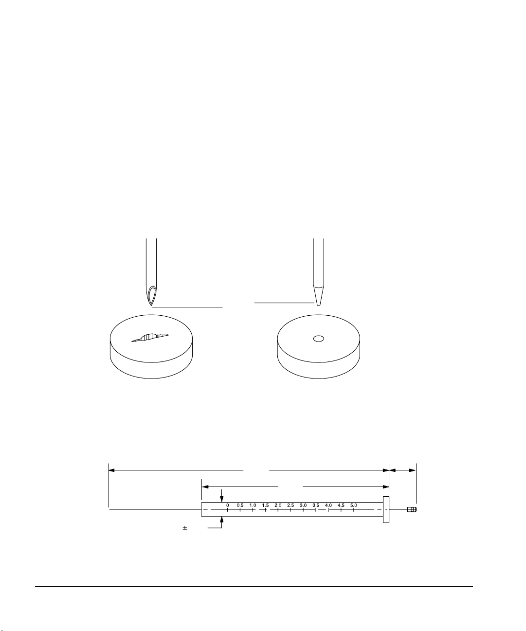
Inspecting syringes
Before installing the syringe:
1. Roll the syringe on the edge of a clean flat surface. If the tip of the needle
seems to follow a circular motion, bend it slightly near where it connects
to the syringe barrel, and check it again.
Bend here if necessary
Figure 39. Syringe parts and needle inspection
2. Check for a rough needle. The needle may contain closely spaced
concentric ridges that act like a miniature file and abrade pieces of the
septum into the inlet. The ridges are easy to see under 10X magnification.
51
Page 61

Preparing for Operation
Selecting and installing syringes
If there are ridges, polish the needle by pulling it through a folded piece of
fine emery paper between your finger and thumb until the ridges are gone.
Be careful not to modify the special blunt tip of the syringe.
3. Check for a sticky plunger. Slide the plunger of the syringe up and down a
few times. It should move smoothly without sticking or binding. If it is
sticky, remove the plunger, and clean it with solvent.
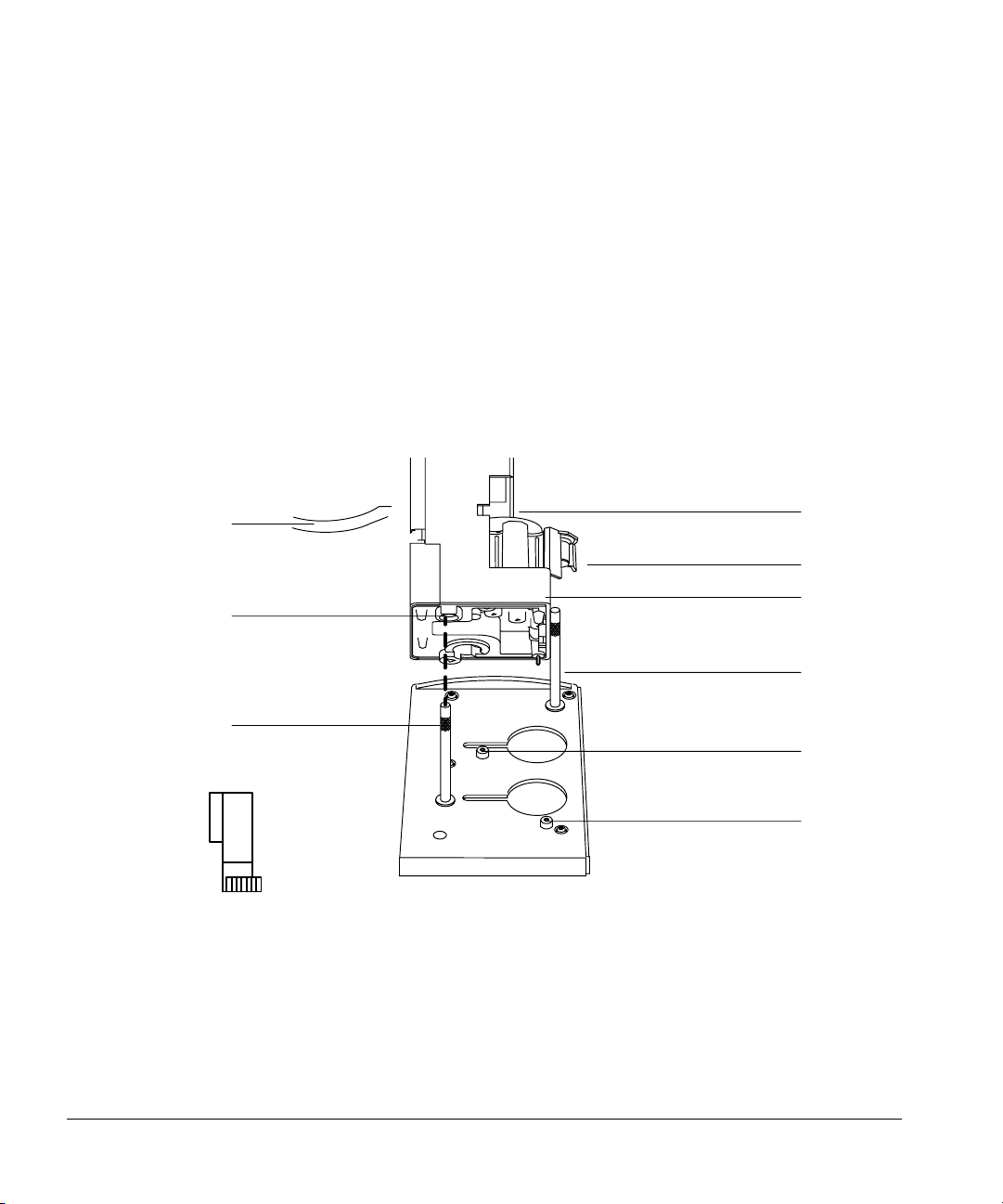
Installing syringes
After completing this task, check your work with the following instructions:
1. Open the injector door.
2. Pass the syringe needle through the hole in the needle support foot.
3. Align the syringe barrel with the flange guide and syringe clip. Press the
syringe in place, keeping the needle in the hole of the needle support foot.
4. Close the syringe latch by swinging it clockwise.
52
Plunger carrier
Plunger screw
Slide
Flange guide
Syringe latch
Syringe clip
Needle support foot
Flange
Figure 40. Installing the syringe in the syringe carriage and needle support
Page 62

Preparing for Operation
Selecting and installing syringes
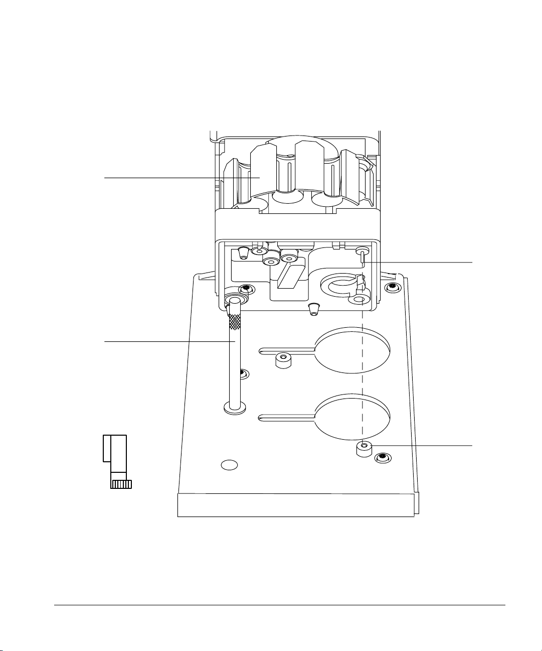
5. Move the plunger carrier loop down and tighten the plunger screw.
Checking your work
❐ Move the plunger carrier up and down. If the syringe plunger does not move
along with the carrier, repeat the previous steps. Be sure the plunger carrier
screw is tight.
❐ Check that the needle is aligned with the needle guide in the foot by moving
the slide up and down. The needle should slide smoothly in the needle guide.
Plunger carrier
Plunger carrier screw
Slide
Flange guide
Syringe latch
Syringe clip
Needle support foot
Figure 41. Plunger carrier and needle support with needle installed
Caution Failure to use the on-column syringe when injecting into an on-column inlet
could damage the injector, syringe, and column.
53
Page 63

Preparing for Operation
Maintaining the inlet
Caution Do not operate the injector without a syringe in place because the syringe latch
may interfere with the motor if it is allowed to swing freely.
❐ To check the alignment of the syringe needle to ensure an average septum
life of 200 injections, follow these instructions:
1. Pull down the syringe carriage until the needle tip is near the top of the
inlet septum nut. The needle should be centered exactly over the hole in
the septum retainer nut. Use a small light to see that the needle will hit the
septum without rubbing on the nut.
2. If it is not centered, check that the syringe is installed correctly in the
syringe carriage, the syringe needle is straight, and the mounting bracket is
aligned with the inlet.
Maintaining the inlet
This section contains inlet information to help you maintain good chemical
performance from your GC.
Changing septa
The average life of an inlet septum should be 200 injections. This is influenced
by the alignment of the injector bracket, the syringe, and the type of septum.
When you replace the septum:
• Clean off the metal surfaces that create the seal.
• Replace with the correct septum.
• Make sure the bottom of the septum is flat against the base.
• For packed and split/splitless inlets, tighten the septum retainer nut only
until the split ring begins to turn on the top of the nut.
Caution Do not tighten the septum retainer nut too much. The syringe needle will core
the septum and push out pieces of the septum material into inlet. Septum life is
often reduced to as few as five injections.
54
Page 64

Preparing for Operation
Adapting for cool on-column injection
Changing or cleaning liners
Most samples contain nonvolatile material that accumulates on and partially
pyrolyzes on the liner. Replace the liner or clean the liner periodically.
Some active components interact with the glass liner and glass wool plug of the
capillary liner. If these components are in the sample, the liner should be
deactivated before installation and periodically replaced or cleaned and
deactivated. There are several commercially available solutions for
deactivating the liner. Take the appropriate safety precautions when using any
of these solutions. Refer to the Agilent analytical consumables and supplies
catalog for deactivated liners.
Suggestions for packed inlets with 530-µm columns
When using a heated, packed inlet with a 530-µm column, do the following:
• Install the column so that no more than 1 to 2 mm of the column extends
past the ferrule. This avoids large unswept volumes at the base of the inlet.
• Use polyimide ferrules (Vespel) instead of graphite. A small portion of the
column ferrule is exposed to sample vapor.
• Insulate the part of the inlet that projects into the oven. If the oven is
programmed to increase temperature, the lower part of the inlet could
become a cold spot.
Adapting for cool on-column injection
For cool on-column inlets, you must specify on-column injection with the
sampler parameters so that the injector:
• Slows the carriage speed to 500 milliseconds. The syringe needle moves
more slowly into and out of the inlet and spends more time in the inlet.
• Lowers the tip of the syringe needle an additional 19 mm (3/4-inch) to the
column.
You can use the slow injection parameter along with on-column injection. This
adds the following change to the injection:
55
Page 65

Preparing for Operation
Adapting for cool on-column injection
• Slows the plunger speed to 1/18 the normal speed
Complete the following:
1. Install an on-column syringe. Agilent Technologies recommends syringes
with a 23/26 gauge tapered-tip needle for injections onto 530-µ columns
and 32/26 gauge for 320- and 250-µ columns.
2. If the injector is controlled by an external device, such as an integrator or
a workstation, change the on-column parameter to ON or YES.
If the injector is controlled by a 6890 GC, this will be set automatically
when the GC configures for the on-column inlet.
If the injector is operated with standalone control, change the on-column
switch to the YES, or down, position. For more information on the oncolumn switch, see “On-column injection mode” in chapter 4.
3. The inlet must be configured for cool on-column injection. Install the
appropriate needle guide, septum, spring, and insert for the GC.
If you have an on-column inlet on a 5890A GC with a cooling tower
(part no. 19245-20540), replace it with a septum nut base assembly
(part no. 19245-80520).
56
If you are performing automated injection onto 320-µm and 250-µm
columns, replace the standard septum nut base assembly (part no.
19245-80520) with the small septum nut base assembly (part no.
07673-61330)
4. For injecting onto 320-µm or 250-µm columns, see “Performing cool oncolumn injection onto 250-µm and 320-µm columns” in chapter 6.
Page 66

3
Operation
Page 67

Operation
This chapter contains detailed information for operating the automatic liquid
sampler, including:
• Setting the run parameters
• Starting and stopping the automatic liquid sampler
• What happens during a run
• Running the samples
• Four methods of control
• Using two injectors
• Examples of operation
58
Page 68

Operation
Setting the run parameters
Setting the run parameters
This section describes each run parameter, lists the range of values for the
common controlling devices, and contains three examples.
The run parameters tell the injector and the tray what to do. For example, they
tell the injector how much sample to inject and tell the tray where to find
sample vials. You can set many of the parameters either with the control
switches of the injector or with an external device, such as an integrator,
ChemStation, or the 6890 Series GC.
For information about setting parameters with the control switches on the
injector panel, see chapter 4, “Standalone Control.”
Description of the parameters
Injections per vial
Specifies the number of times the run is repeated for each sample vial. For
example, if the value is two, each vial is analyzed twice.
Caution Too many injections per vial can allow sample to evaporate, deplete sample, or
contaminate sample in the vial. This may affect the reproducibility of the
injection volume.
Position of first vial
Specifies the tray or injector turret position of the first sample vial. Each
position on the tray and turret is numbered. Tray values range from 1 to 100.
Only three sample positions are available in the standard injector turret.
Position of last vial
Specifies the tray or injector turret position of the last sample vial. Tray values
range from 1 to 100. Only three sample positions are available in the standard
injector turret.
59
Page 69

Operation
Setting the run parameters
Number of sample washes
Specifies the number of times the syringe is rinsed with sample before the
injection. The injector lowers the needle into the sample vial, fills the syringe to
eight-tenths its full volume, and empties it into one of the waste bottles.
Number of sample pumps
Specifies the number of times the syringe plunger is moved up and down while
the needle is in the sample to expel air bubbles and improve reproducibility.
Viscosity delay
Specifies the number of seconds the plunger pauses at the top of the stroke
during sample pump, sample draw, and sample and solvent washes. For
viscous samples, the pause during sample draw allows the sample to flow into
the vacuum created by the syringe. During wash strokes, it allows diffusion of
the viscous sample into the wash solvent. Viscosity delay settings range from
0–7 seconds.
60
Solvent washes—pre- and post-injection
Number of solvent A washes: Specifies the number of times the syringe is
rinsed with solvent from the solvent A bottle. The injector lowers the needle
into the solvent A bottle, fills the syringe to eight-tenths its full volume, and
empties it into one of the waste bottles.
Number of solvent B washes: Specifies the number of times the syringe is
rinsed with solvent from the solvent B bottle. The injector lowers the needle
into the solvent B bottle, fills the syringe to eight-tenths its full volume, and
empties it into one of the waste bottles.
Volume
Specifies the injection volume. Each volume stop corresponds to a volume of
one-tenth the syringe’s capacity. Valid setpoints are 1–5 stops.
Page 70

Operation
Setting the run parameters
Caution Do not set the volume parameter for splitless inlets more than 2 µl. Larger
volumes cause sample to be lost through the purge vent and may contaminate
carrier inlet lines.
Dwell time
This setpoint specifies the time delay of the needle in the inlet for both pre- and
post-injection. This adds the following changes to the injection parameters:
• Preinjection dwell: Time delay of the needle in the inlet before the plunger
is depressed to inject sample. When preinjection dwell is selected, one
stop of air is drawn after the sample for volume settings from 1–4 stops.
With a setpoint of five stops, no air is drawn.
• Postinjection dwell: Time delay after injection before needle is withdrawn
from the inlet
The allowable range for both dwell times is 0–1 minute in increments of
0.01 minute.
Priority samples
This setpoint specifies whether the arm of the tray should look for a priority
sample in position 100 between runs. If the feature is turned on, the tray checks
position 100 before each regular vial in the sequence. If a vial is in position 100,
the tray arm delivers the vial to the injector turret. After the injection, the tray
arm places the vial in position 99.
If you are using the priority sample feature, use only tray positions 1 to 98.
Slow injection
This setpoint specifies the speed of the syringe plunger during the injection
stroke and whether or not the syringe needle stays in the inlet (dwell time)
after injection of the sample. It enables you to reduce the average speed of the
plunger from about 100 µl/sec to about 5 µl/sec (with a 10-µl syringe). This
61
Page 71

Operation
Setting the run parameters
parameter also holds the syringe in the inlet for 4 seconds after the injection.
The plunger speed during the pump and waste dispensing does not change.
Sample
in needle
inj:
fast
slow
Switch setting
Fast, no dwell
Up
Slow, with dwell
Down
Figure 42. Injection speed
Caution The slow setting is recommended only for a few specific splitless and cool on-
column applications. For most applications, set this switch to “fast.” A setting
of “slow” for other applications may cause peak area discrimination and
reduced quantitative precision.
Slow plunger
This setpoint specifies the speed of the syringe plunger during injection. It
enables you to reduce the average plunger speed. The plunger speed during the
pump and waste dispensing does not change. Selecting slow plunger reduces
the rate to about 5 µl/sec, compared to the fast speed of about 100 µl/sec (with
a 10-µl syringe).
62
Page 72

Operation
Setting the run parameters
Sampling depth
This setpoint allows you to move the position of the needle tip up or down to
approximate locations from the nominal position of zero (default). Default is
the standard position (see Figure 43).
Standard position
1 ml
3.6 mm*
*Measure from bottom of vial.
2-ml vial
Figure 43. Variable sampling depth
Injection mode
Specifies whether the injector is in the normal or on-column injection mode.
The normal injection mode is used with packed and split/splitless inlets. The
on-column injection mode is used with cool on-column inlets. For the oncolumn injection mode, the injector reduces the carriage speed and lowers the
tip of the syringe needle an additional 19 mm (3/4-inch) into the column.
Caution Be sure you are using the correct injection mode. If you use the wrong
injection mode, you may damage the column, needle, and syringe.
For more information on setting up the inlet for on-column injection, see
Chapter 4 of the Agilent 6890 Series Gas Chromatograph Operating Manual
or the Agilent 5890 Series II and Series II Plus Programmable Cool
On-Column Manual.
63
Page 73

Operation
Setting the run parameters
Position
This setpoint indicates which tower is on which inlet (front or back). Typically,
the location of the injector cable in the controller box, front or back, is the
position associated with that injector.
With an INET integrator and dual injectors, this setpoint specifies which
injector, front or back, is associated with the INET data channel and which is
associated with the auxiliary data channel. This parameter determines where
the sample vial numbers are printed when more than one injector is installed.
On the 6890 Series GC, the position of the injector cables are not significant
because you can set the injector position from the keypad. With only one
injector, you no longer have to move the cables when you move the tower,
merely reconfigure the tower position.
Caution Always turn off the power to the controller before you remove and reconnect
the injector cables.
64
Page 74

Table 4. Range of Values for Common Controlling Devices
Operation
Setting the run parameters
6890 and Multitechnique
Parameter
Injections per vial 1 to 99 0 to 15 1 to 99
Position of first and last vials (front) 1-3, 101-103, or 1-100 1-3 or 1-100 1-3 or 1-100
Position of first and last vials (back) 1-3, 201-203, or 1-100 1-3 or 1-100 4-6 or 1-100
Number of sample prewashes 0-15 0-15 0-15
Number of pumps 0-15 0-15 0-15
Variable sampling depth -2 to 30 mm n/a n/a
Viscosity 0-7 sec 0-7 sec 0-7 sec
Volume (tenths of syringe volume) 1-5 1-5 1-5
Number of solvent A washes (post) 0-15 0-15 0-15
Number of solvent A prewashes 0-15 0-15 0-15
Number of solvent B washes (post) 0-15 0-15 0-15
Number of solvent B prewashes 0-15 0-15 0-15
Preinjection dwell 0-1 min n/a n/a
Postinjection dwell 0-1 min n/a n/a
Priority samples Create sequence 0=no, 1=yes Create special method
On-column injection mode Set by GC
Normal mode 0 no
On-column mode 1 yes
ChemStation*
3396 INET
Integrator 3365 ChemStation**
Variable plunger speed yes/no
Fast 1 1
Slow 0 0
Position 1=front, 2=back In instrument definition
* MS ChemStation rev 3.71 and above
**MS ChemStation rev 3.65 and below
65
Page 75

Operation
What happens during a run?
What happens during a run?
In the following description, the run parameters that determine the automatic
liquid sampler’s actions are surrounded by quotes (“run parameter”). From the
point when you start the run, the automatic liquid sampler does the following:
1. The syringe carriage, plunger carrier, injector turret, tray arm, and gripper
move to their home positions.
2. With a tray, the tray gripper picks up a vial from the “position of first vial”
and delivers it to the injector turret associated with sample position.”
Without a tray, the samples are already in the injector turret.
3. If this is the first sequence after the power is turned on, the injector goes
through a solvent “prewash” and pauses for “viscosity delay.”
4. The injector lowers the syringe into the vial (“sampling depth”). The
injector fills the syringe with sample, pauses for “viscosity delay,” and
dispenses it into one of the waste bottles according to the “number of
sample washes.”
66
5. The injector fills the syringe with sample and dispenses it back into the
sample vial according to the “number of pumps.” The syringe plunger may
pause at the top of the pump stroke according to the “viscosity delay.”
6. The injector fills the syringe with the “volume/stop” of sample. The syringe
plunger may pause at the top of the injection stroke according to the
“viscosity” then draws up one stop of air for “predwell.” The injector then
lowers the syringe into the injection port, remains for the “preinjection
dwell,” injects it, applying “plunger speed”, and holds it for the
“postinjection dwell time.”
7. The injector fills the syringe with solvent from solvent bottle A, pauses for
“viscous delay” with the syringe over the waste bottle, and dispenses it
into one of the waste bottles according to the “number of solvent A
washes.”
8. The injector fills the syringe with solvent from solvent bottle B, pauses for
“viscosity delay” with the syringe over the waste bottle, and dispenses it
into the same waste bottle according to the “number of solvent B washes.”
9. With a tray, the tray gripper picks up the vial and returns it to its original
position in one of the tray quadrants.
Page 76

Operation
What happens during a run?
The injector waits until the GC sends a ready signal to continue. Steps 1, 2, and
3 through 9 are repeated according to the “injections per vial.”
With a tray, the steps are repeated until the tray returns the last sample to the
“position of last vial.” Without a tray, the steps are repeated according to the
rotary switch setting.
If the “priority sample” feature is turned on, the tray gripper looks for a sample
in tray quadrant position 100 after each vial. After a priority sample is run, the
tray returns it to tray quadrant position 99.
67
Page 77
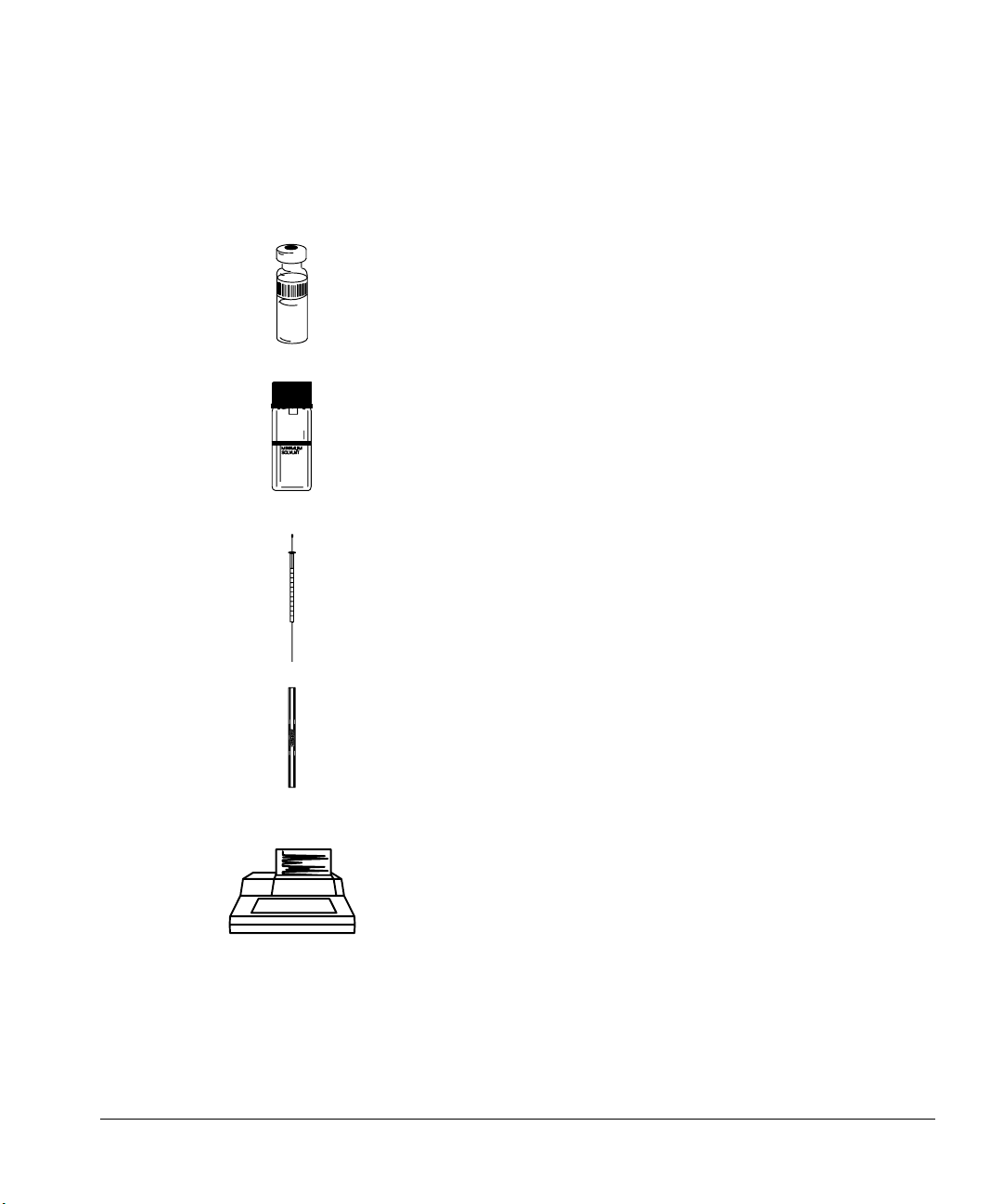
Operation
Checklist
Checklist
Use this checklist to make sure the sampler is ready before you begin.
❐ Sample vials are half full
❐ Cap centered, no wrinkles, septum is flat
❐ Sample inserts and vials match the run parameters
❐ Tray quadrants snapped in place
❐ 4.5 ml of fresh solvent in each solvent bottle
❐ Waste bottles are clean and empty
❐ Two waste bottles (with tray)
❐ Limit to number of sample vials
❐ New or clean syringe
❐ Correct syringe design and size
❐ Plunger carrier holds plunger button
❐ Needle is aligned with septum retainer nut
❐ Syringe is rinsed with solvent
68
3396
❐ Liner is clean and deactivated
❐ Liner is correct type for injection technique
❐ Septum type is correct
❐ Septum is less than 200 injections old
❐ Correct septum nut
❐ Injector run parameters are set correctly
• Injection mode matches type of inlet
• Number of injections per vial is less than five
• Injection volume is not greater than 2 µl for splitless
inlet
Page 78

Operation
Running the samples
Running the samples
This section describes starting and stopping a run or sequence and the
movements of the automatic liquid sampler during a run.
Starting a run or sequence
After completing the checklist above, start the run or sequence by pressing the
start button on the injector or entering the appropriate command at your
controlling device.
Stopping or interrupting a run or sequence
The following events interrupt a run:
1. The power to the controller or controlling device fails.
2. You press the stop button or Stop/Abort from a ChemStation.
3. The sampler recognizes a safety or operator fault, such as:
• You open the syringe access door.
• The tray gripper drops a sample vial.
• The syringe needle hits the metal side of the crimp cap.
The sampler responds to these interruptions differently depending on the
controlling device. With standalone control, any of the interruptions causes the
automatic liquid sampler to stop and abort a sequence.
With the 3396 integrator and INET communications, power failures only
interrupt the sequence. The integrator recovers and restarts the sequence with
the last sample run on the automatic liquid sampler. If the interruption is
caused by number 2 or 3, the run is aborted, and the sequence must be
restarted.
If the interruption was caused by a problem that the sampler recognizes, it
provides you with some feedback by a combination of flashing LED indicators
or error messages or a ChemStation message. For more information, see
chapter 5, “Preventive Maintenance and Troubleshooting.”
69
Page 79

Operation
Using two injectors
To restart an aborted sequence from the point of interruption:
1. Identify the last sample vial that was run successfully. Check the vial
number of the last successful chromatogram.
2. Reset the parameter that identifies the first sample vial to the next vial
number.
3. Press the stop button to clear any faults.
4. Start the revised sequence from your controlling device. From the
multitechnique ChemStation, you can run a partial sequence to keep the
original sample numbers.
Using two injectors
Two-injector configurations have the following characteristics:
• Input and output signals are shared.
• The system sends only one injector ready signal to the GC when both
injectors are ready and one start signal at the beginning of the injection
stroke.
70
• The injectors can operate in the synchronous mode (both inject
simultaneously).
The capabilities of a two-injector configuration vary with the communication
device.
For information on using two injectors with standalone control or for
operation in asynchronous standalone mode, see chapter 4, “Standalone
Control.”
With a tray
The tray delivers sample vials to the front and back injectors according to the
run parameters. There is a separate set of run parameters for each injector.
The tray delivers vials to the front injector before the back injector.
Page 80

Operation
Using two injectors
When you set up the run parameters, you must identify which data channel is
for which injector.
Different communication devices assign the position and data channel
differently.
• Using a 6890 Series GC, the channel is assigned when you set up the
sequence.
• Using the ChemStations, you assign the channel when defining the
instruments.
• Using the 3396 integrator (INET), you assign the channel when you set up
the run parameters for the second injector.
Once both injectors have samples, they begin the injection cycle, including any
sample washes. After both injectors have completed the specified sampling
steps, they inject the samples. After the injection, both injectors go through the
solvent wash cycle. When both injectors are done, then the tray picks up the
sample vial from the front injector first and returns it to its original position on
the tray, then picks up the vial from the back injector and returns it to its
original position.
When the parameters tell the tray arm to deliver the same sample vial to both
injectors at the same time, the tray delivers the vial to the front injector first.
After the injection, the tray arm delivers this sample to the back injector and
delivers the next sample vial in the front injector sequence to the front injector.
These samples are injected at the same time. Similarly, if the first and last
sample vial parameters are the same for both injectors, the samples are
injected in the synchronous N-1 injection mode (see Figure 44).
Note: The ChemStation method for a single run will not allow you to set the
same vial number for front and back injector, however, you can run a dualcolumn sequence with a single set of vials.
71
Page 81

Operation
Using two injectors
Front Injector Back InjectorInjection Number
1st
2nd
3rd
.
.
.
nth
Last
Vial 1 Idle
Vial 2 Vial 1
Vial 3 Vial 2
.
.
.
Vial n Vial n-1
Idle Vial n
.
.
.
Figure 44. Synchronous N-1 injection mode
To inject the same sample into the front and back inlet in the same run, you
must do the following:
1. Prepare two sets of sample vials, two vials for each sample.
2. Place the sets in two different locations in the quadrants.
3. Set up the sequence parameters so that the tray delivers the first bottle of
one set to the front injector and the first bottle of the other set to the back
injector.
For example, with ten samples, you must have 20 vials (two vials for each
sample). Place one vial of each in tray positions 1 to 10. Place one vial of each
in tray positions 11 to 20. Set the first vial position for the front injector to 1
and the last vial position to 10. Set the first vial position for the back injector to
11 and the last vial position to 20.
72
Without a tray
The injectors go through the same motions as with a tray. The injectors inject
samples from position 1 first, followed by samples from positions 2 and 3. If the
two injectors do not have the same number of samples, the injector that
completes its sequence first remains idle while the other finishes.
You can mount two injectors onto the 6890, the 5890, and the 5880 GCs. You
cannot mount two injectors onto 5700 Series GCs.
Page 82

Operation
3396
Four methods of control
Four methods of control
There are a number of ways to control the automatic liquid sampler. Each
controlling device allows different functionality when using the G1513A or
18593B injectors. Always check the manual of your chosen controlling device
for exact feature sets.
Agilent 6890 Series GC control
Multitechnique ChemStation control with a
5890 or 6890 Series GC, the 3365 ChemStation
control (MS-DOS series) with a 5890 GC, or
the MS ChemStation.
Agilent 3396 integrator using the Instrument
Network (INET) with a 5890 or 6890 series GC.
Standalone control with a 5890 or 5700 series GC.
73
Page 83

Operation
Examples of operation
Examples of operation
This section describes the basic steps to set up your automatic liquid sampler
using different methods of control. The following examples are for three
specific systems with one injector module mounted over the front inlet. For
more information on other types of configurations, see the manual of your
controlling device.
• 6890 Series GC
• 3396 integrator with a 5890 GC
• Multitechnique ChemStation with a 6890 Series GC
• 3365 ChemStation (MS-DOS Series) with a 5890 GC
For information on controlling the automatic liquid sampler without an
external instrument, see chapter 4, “Standalone Control.”
To complete the following examples successfully, the following statements
should be true:
74
• The automatic liquid sampler is installed correctly on the GC.
• The external controlling device is installed and configured correctly.
• You have a basic understanding of the GC and the external controlling
device.
Preparing the GC and controlling device
For a trial run, you can minimize the time for the GC to be ready by setting the
oven to a low temperature, removing any temperature ramp program, and
setting the equilibration time to zero. You can minimize the amount of time the
integrator or computer collects data by turning the detector or signal off and
setting the run time to about 10 seconds.
To set up your automatic liquid sampler for a run, the following examples will
help you get started.
Page 84

Operation
6890 Series GC Control
6890 Series GC Control
The following procedure allows you to configure the setpoints associated with
the injector waste bottle and tower positions.
Configure tower position
Injector cables are connected to either the INJ1 (front) or INJ2 (back) port
on the controller. This setpoint indicates which tower is on which inlet. With
only one injector, you no longer have to move cables when you move the
tower, merely reconfigure the tower position.
Configure waste bottle position with a tray
The turret waste bottle positions are controlled by entering a value of:
• 0 for the A position only
• 1 for the B position only
• 2 to alternate between the two waste bottles
Configure the injector
To configure the injector:
1. Press [Config][Front Injector] or [Config][Back Injector].
Specifies tower identity
Specifies turret waste bottles
2. With the cursor on a tower line, use the [On] or [Off] key to set the tower
position to either INJ1 or INJ2.
3. Enter a value for Waste bottle use.
When the tray is disabled, only waste A is used.
75
Page 85
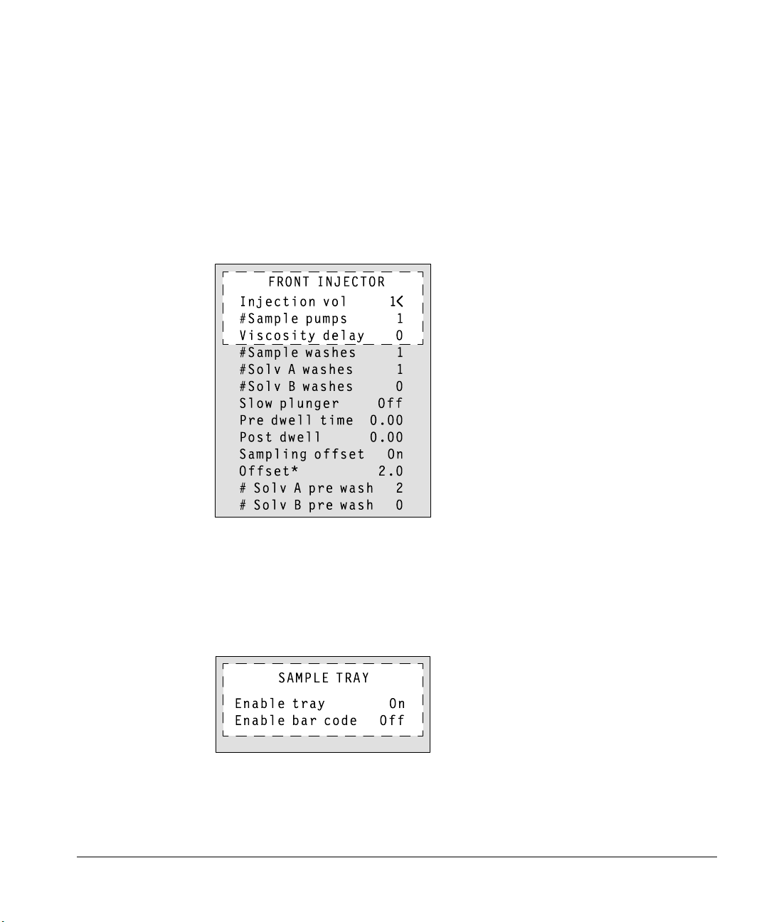
Operation
6890 Series GC Control
Injector parameter setpoints
To enter injector setpoints:
1. Press [Front Injector] or [Back Injector].
2. Scroll to the desired setpoint.
3. Enter a setpoint value, or turn the setpoint on or off.
76
*The Offset line appears only when “On” is selected.
Sample tray setpoints
1. Press [Sample Tray] to access the sample tray and bar code reader
setpoints.
2. Press [On] or [Off] to enable or disable the tray.
3. Press [On] or [Off] to enable or disable the bar code reader.
Page 86

Operation
6890 Series GC Control
Storing injector setpoints
After setting up injector setpoints, sample tray setpoints, and bar code reader
configurations, store them as part of a method. This method becomes a part of
the sequence used to run the samples.
1. Press [Method], and scroll to the method number you wish to use.
2. Press the [Store] key. Press [Enter] to confirm the store.
Operating in cool on-column mode
When the injector is configured to a cool on-column inlet, the on-column mode
is selected automatically.
77
Page 87
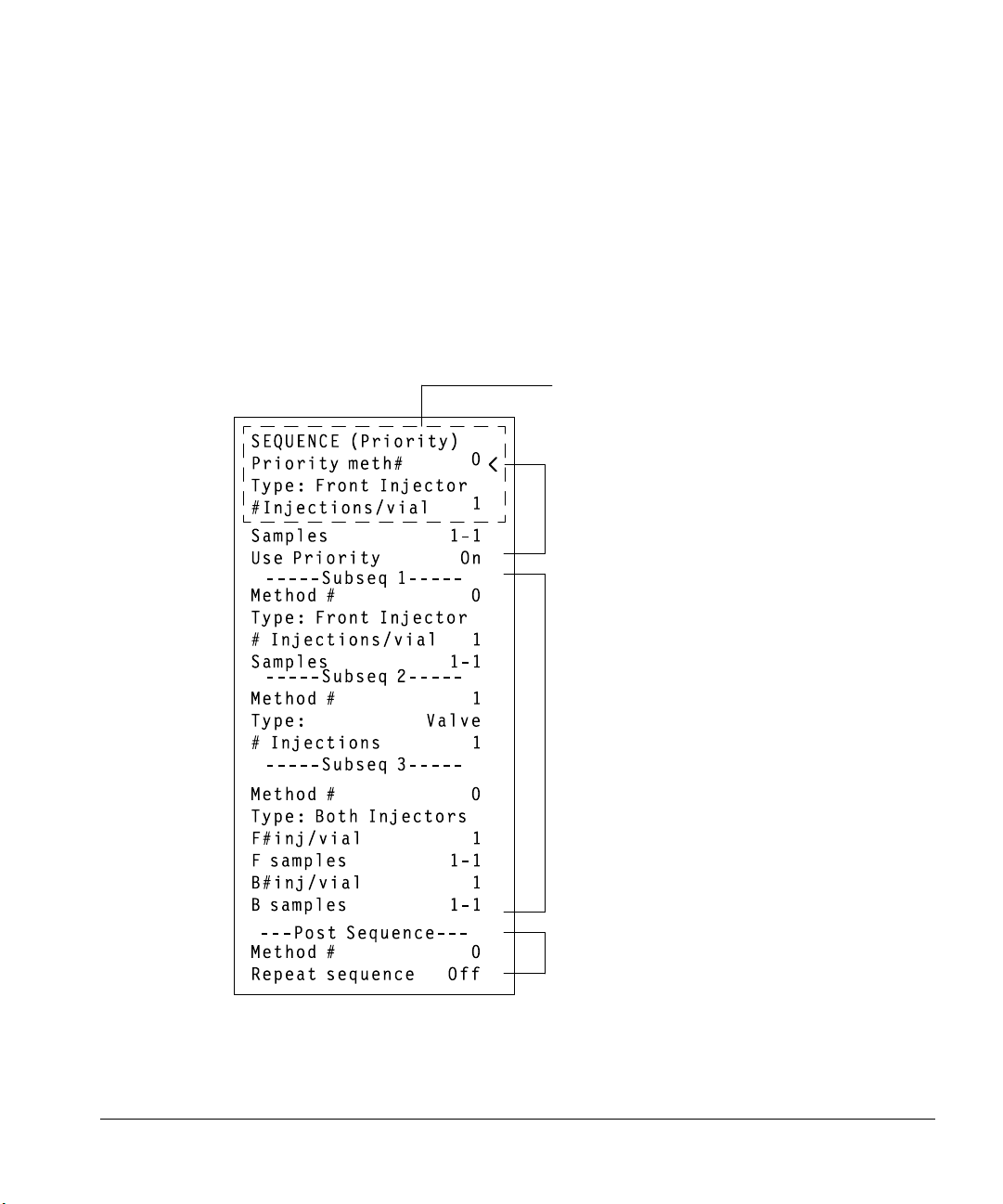
Operation
6890 Series GC Control
Creating a sequence
A sequence specifies which samples to run and the stored method to be used
for each. It is divided into subsequences, each of which uses a single method
plus a priority sequence and postsequence events.
The sequence definition control table is accessed by pressing [Seq]. The [Seq]
key toggles between the stored sequence control table and the
sequence definition control table (Figure 45).
Title line changes as
cursor moves in table
Priority sequence
78
Subsequence
Postsequence events
Figure 45. Sequence definition control table
Page 88

Operation
6890 Series GC Control
When in the sequence control table, you will find the [Info] key useful if an
explanation of sequence parameters is needed.
Storing a sequence
Up to five sequences can be stored.
1. To store a sequence, press [Store][Seq]. This opens the Store Sequence
control table.
2. Enter an identifying number for the sequence.
3. Press [Enter] to store the sequence.
If the sequence number you specified already exists, you will be prompted to
either:
• Overwrite the existing sequence, which will replace the existing sequence
with the new sequence.
79
Page 89

Operation
6890 Series GC Control
• Cancel the store, and return to the STORED SEQUENCES status table.
Sequences can also be stored from within the STORED SEQUENCES status
setpoint table by scrolling the cursor to the appropriate sequence number and
pressing the [Store] key.
Starting/running a sequence
Press the [Seq Control] key, scroll to the Start sequence line, and press
[Enter].
80
Pressing [Enter] changes the sequence status to Running.
If a sequence is started and the instrument is not ready (due to oven
temperature, equilibration times, etc.), the sequence will not start until all
instrument setpoints are ready.
Page 90

Operation
Special considerations when using an integrator with a 6890 Series GC
Special considerations when using an integrator with a
6890 Series GC
The definitions of sequence are not the same in the 6890 Series GC and in the
3396 integrator. The following points must be considered when sequences are
used with this GC/integrator combination:
• The integrator has only one subsequence plus the priority sequence. Only
one GC method can be used within an integrator sequence.
• The automatic liquid sampler method parameters are prepared using the
[Front Injector] and [Back Injector] keys on the 6890 keyboard.
• The sample information table is prepared on the integrator.
• The injection sequence parameters can be prepared either with the [Seq]
key on the 6890 GC keyboard or in the [PREP][SEQ] dialog of the 3396.
Setting sequence parameters on either instrument changes the sequence in
both places.
• The Start sequence function on the GC is inactive.
• A sequence must be started from the integrator using [SEQ][START].
• If you use INET, pressing the stop key on either instrument stops the run
and aborts the sequence.
• If you use the part no. 03396-61010 cable instead of INET, the two stop
keys have different effects. The [STOP] key on the integrator stops the
current run and aborts the sequence. Stop on the GC stops the current run,
but the sequence continues as soon as the GC becomes ready.
For more information on the 6890 Series GC, see “Using Sequences” in the
Agilent 6890 Series Gas Chromatograph Operating Manual.
81
Page 91

Operation
Special considerations when using an integrator with a 6890 Series GC
Figure 46 shows an example of the injector parameter portion of a method
printout using a 6890 Series GC, a 3396 integrator, and a G1513A injector in the
front position and a 18593B in the back position.
* LIST: METH @
INJECTOR 1
Injection vol 1
#Sample pumps 5
Viscosity delay 0
#Sample washes 1
#Solv A washes 3
#Solv B washes 3
Slow plunger Off
Pre dwell time 0.00
Post dwell 0.00
Sampling offset On
Offset 0.0
#Solv A pre wash 0
#Solv B pre wash 0
Front tower INJ1
Waste bottle use 2
82
*
INJECTOR 2
Injection vol 1
#Sample pumps 6
Viscosity delay 0
#Sample washes 0
#Solv A washes 0
#Solv B washes 0
Slow injection Off
Back tower INJ2
Waste bottle use 2
Figure 46. Injector parameters on a 3396 integrator with a 6890 GC
Page 92

Operation
3396 integrator with a 5890 GC
3396 integrator with a 5890 GC
1. Set the run time to 0.1 minutes by pressing [TIME] [.] [1] [STOP].
2. Begin the dialog to prepare a sequence by pressing the keys for [PREP]
[SEQ].
3. Answer yes to INET SAMPLER CONTROL by pressing [Y] [ENTER].
4. Select INJ1 by pressing [ENTER].
* TIME .1 STOP
* PREP SEQ
ALS INFORMATION
INET SAMPLER CONTROL [Y*/N] : Y @
7673C SAMPLER:
LOOP ADDRESS: 8
ENABLE TRAY (1=YES) 1 —>
FRONT INJECTOR
INJ/BOTTLE 3 —>
Figure 47. 3396 integrator with a 6890 GC
5. Set the number of injections per sample vial to one.
INJ/BOTTLE 1 --> Press [1] [ENTER].
6. Identify the location of the first sample vial.
FIRST BOTTLE --> Press [1] [ENTER].
7. Identify the location of the last sample vial.
LAST BOTTLE --> Press [3] [ENTER].
8. Set the number of sample washes per sample vial to two.
# OF SAMPLE WASHES --> Press [2] [ENTER].
9. Set the number of pumps to six.
# OF PUMPS --> Press [6] [ENTER].
83
Page 93

Operation
3396 integrator with a 5890 GC
10. Set the viscosity delay to zero.
VISCOSITY --> Press [0] [ENTER].
11. Set the sample size (injection volume) to 1 ml.
VOLUME --> Press [1] [ENTER].
12. Set the injection speed to fast.
SLOW INJECTION --> Press [0] [ENTER].
13. Set the number of solvent A washes to one.
# OF SOLVENT A WASHES --> Press [1] [ENTER].
14. With a tray, set the number of solvent B washes to one.
# OF SOLVENT B WASHES --> Press [1] [ENTER].
Without a tray, skip to the next instruction.
15. Turn the priority sample feature off.
PRIORITY SAMPLE (1=YES) --> Press [0] [ENTER].
16. Set the injection mode. CAPILLARY ON-COLUMN
84
Normal for capillary or packed inlet.
Press [0] [ENTER].
or
On-column for an on-column inlet.
Press [1] [ENTER].
Page 94

3396 integrator with a 5890 GC
Checking your work
List the parameters by pressing the keys for [LIST][SEQ].
* LIST: SEQ @
ALS INFORMATION
INET SAMPLER CONTROL . . . . . YES
EQUILIBRATION TIME IN SECONDS . . 0
7673C SAMPLER:
LOOP ADDRESS: 8
ENABLE TRAY (1=YES) 1
FRONT TOWER = INJ1
FRONT INJECTOR
INJ/BOTTLE 1
FIRST BOTTLE 1
LAST BOTTLE 3
# OF SAMPLE WASHES 2
# OF PUMPS 6
VISCOSITY 0
VOLUME 1
SLOW INJECTION 0
# OF SOLVENT A WASHES 1
# OF SOLVENT B WASHES 1
PRIORITY SAMPLE (1=YES) 0
CAPILLARY ON-COLUMN 0
*
Operation
Figure 48. 3396 integrator with a 5890 GC
If there are any errors, edit the parameter by pressing the keys for
[EDIT][SEQ].
85
Page 95

Operation
Multitechnique ChemStation control with a 6890 Series GC
Multitechnique ChemStation control with a 6890
Series GC
The following is an example of the multitechnique ChemStation control of the
G1513A injector in the front position and a 18593B injector in the back position
with a 6890 Series GC.
Injector parameters
Use the Injector Parameters dialog box to specify injector parameters for the
automatic liquid sampler. To get the Injector Parameters dialog box, select Edit
Parameters... from the Instrument menu.
Click on the ICON labeled Injector.
86
The enhanced parameters are not available with the 18593B back injector.
Figure 49. Injector parameters dialog box with a 6890 GC
Page 96

Multitechnique ChemStation control with a 6890 Series GC
Washes
Sample (preinjection)
Number of times the syringe is rinsed with the next sample following any
preinjection solvent washes. For each wash, the syringe is filled to
eight-tenths its full volume (4 µl for the 5-µl syringe and 8 µl for the 10-µl
syringe), and then emptied into a waste vial. Valid entries: 0 to 15. The
default entry is 0.
Solvent A (pre- or post-injection)
Number of times the syringe is rinsed with solvent A. For each wash, the
syringe is filled to eight-tenths its full volume (4 µl for the 5-µl syringe and
8 µl for the 10-µl syringe) and then emptied into a waste vial. Valid entries:
0 to 15. The default entry is zero.
Solvent B (pre- or post-injection)
Number of times the syringe is rinsed with solvent B. For each wash, the
syringe is filled to eight-tenths its full volume (4 µl for the 5-µl syringe and
8 µl for the 10-µl syringe) and then emptied into a waste vial. Valid entries:
0 to 15. The default entry is zero.
Operation
Pumps (preinjection)
Number of times the syringe is filled with the next sample prior to
injection. For each pumping stroke, the syringe is filled to eight- tenths its
full volume (4 µl for the 5-µl syringe and 8 µl for the 10-µl syringe), and
then emptied back into the sample vial. Valid entries: 0 to 15. The default
entry is 0.
Position
To specify the front, the back, or both injectors, click on the corresponding
option button. The selection you make here determines which injector
parameters (front, back, or both) become available not only at this dialog box,
but also at the Extended Injector Parameters and Injector Configuration dialog
boxes.
87
Page 97
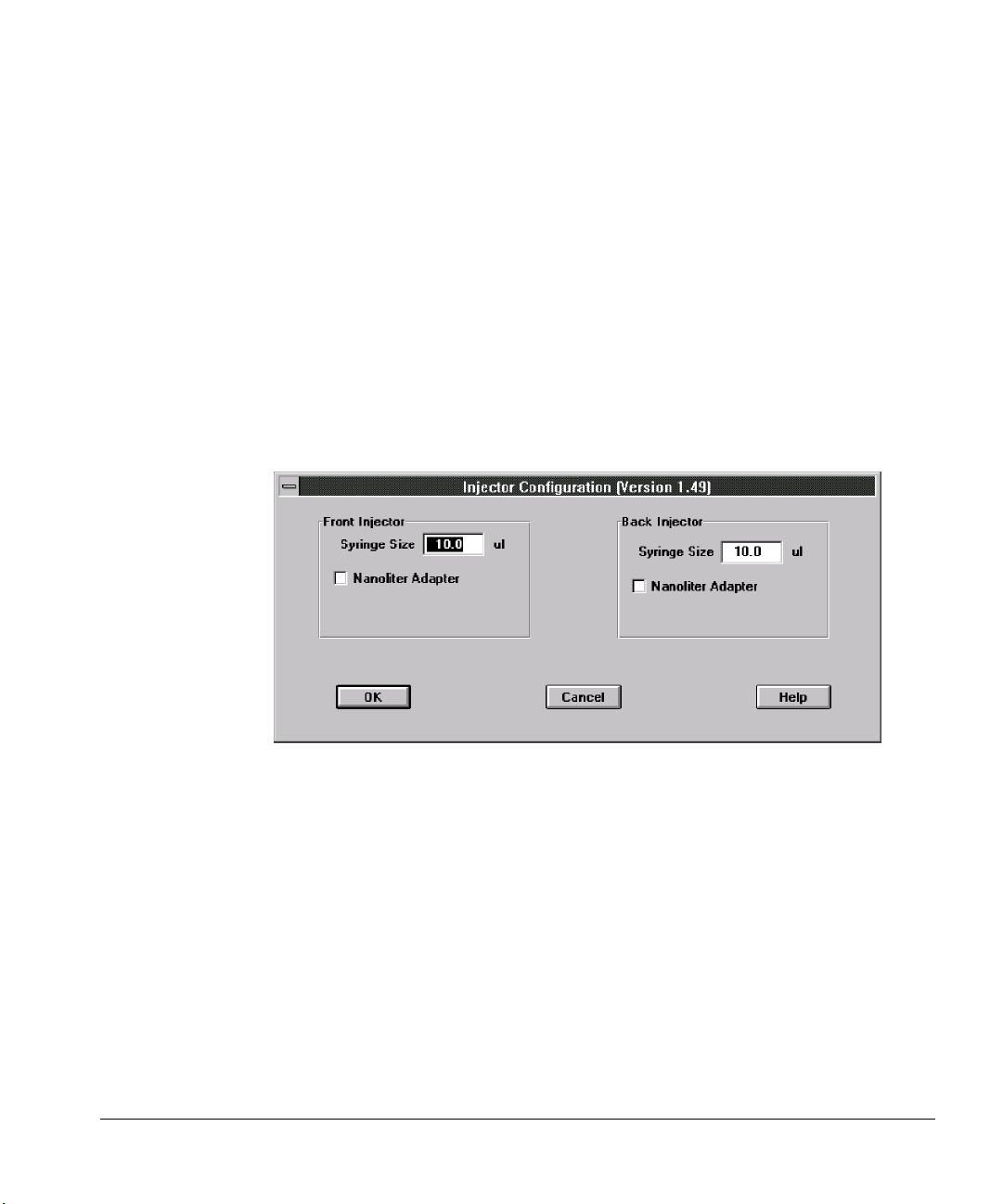
Operation
Multitechnique ChemStation control with a 6890 Series GC
Injection Volume
Injection Volume is the volume (in µl) of sample you want to be injected.
The number of stops is automatically calculated based on your entry for
injection volume and syringe size. You can indicate whether or not you are
using a Nanoliter Adapter at the Injector Configuration dialog box. (Click
on the Configure... button.) See Figure 50.
Syringe Size (5 µl or 10 µl)
Read-only display in this dialog box. You can modify the Syringe Size at
the Injector Configuration dialog box. (Click on the Configure... button.)
See Figure 50.
88
With the 5890 GC, there is also an On-Column Injection check box.
Figure 50. Injector Configuration dialog box
Extended Injector Parameters dialog box
Use the Extended Injector Parameters dialog box to specify additional injector
parameters for the front and/or back injectors (depending on your selection at
the Injector Parameters dialog box).
Page 98
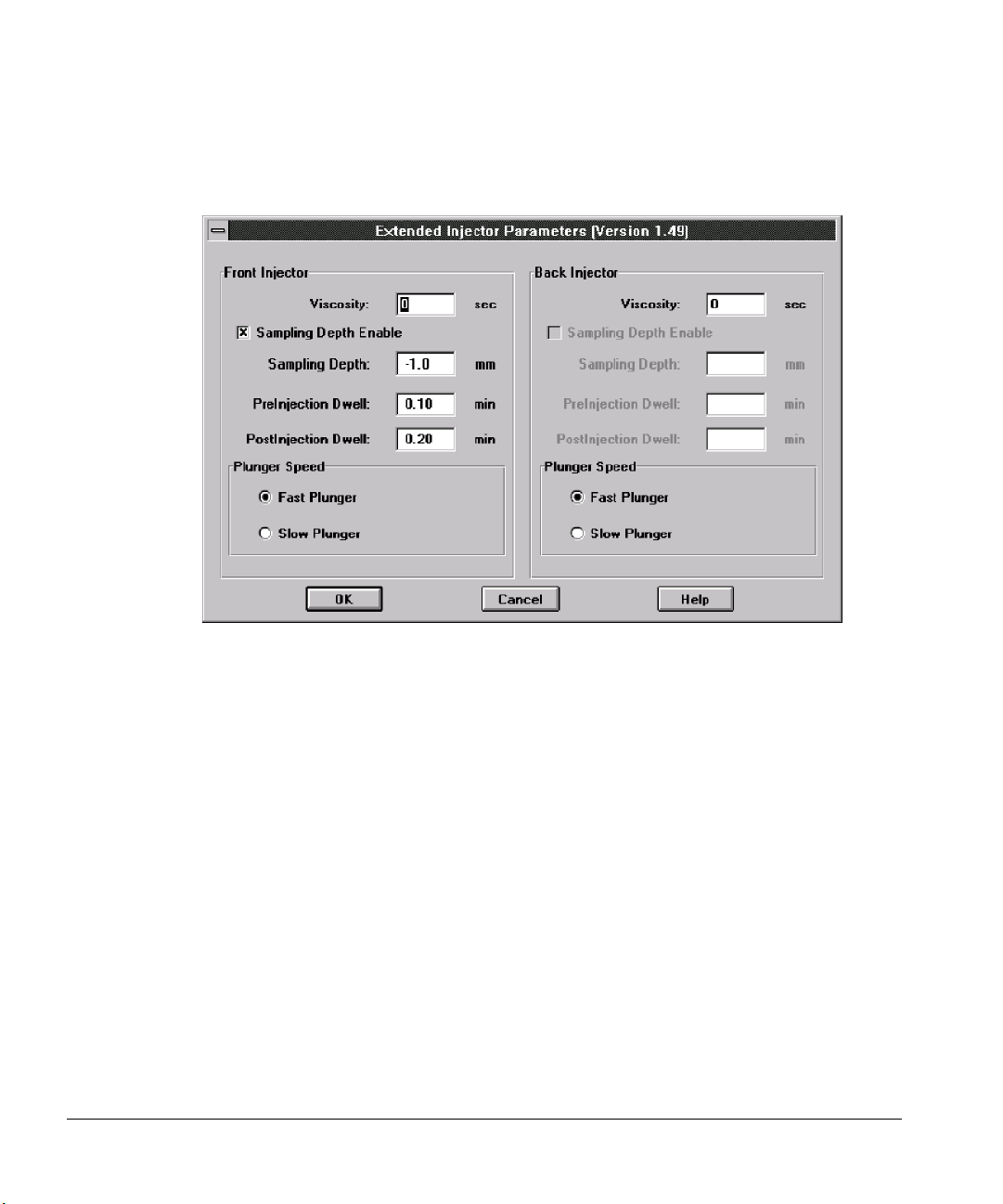
Operation
Multitechnique ChemStation control with a 6890 Series GC
Click on the [More...] button to display the Extended Parameters dialog box.
Figure 51. Extended Injector Parameters dialog box
Viscosity
Number of seconds the syringe plunger should pause between the last
pumping stroke and the injection stroke. For viscous samples, the pause
allows the sample to flow into the vacuum that has been created in the
syringe. The pause during wash strokes allows diffusion of the viscous
sample into the wash solvent. Valid entries: 0 to 7.
Sampling Depth
Depth of the needle tip in the sample vial. Click the check box next to
Sample Depth Enable to enable or disable this function, then Set depth.
When enabled, a sampling depth can be entered in mm as an offset from
standard. (Standard equals zero.)
89
Page 99

Operation
Multitechnique ChemStation control with a 6890 Series GC
PreInjection Dwell
Time in hundredths of a minute for the needle to stay in the inlet before
the plunger is depressed to inject sample. Valid entries: 0.00 to 1.00.
PostInjection Dwell
Time in hundredths of a minute for the needle to stay in the inlet after the
plunger is depressed to inject sample. Valid entries: 0.00 to 1.00.
Plunger Speed
Speed of the syringe plunger during injection. Select a Fast Plunger or a
Slow Plunger speed.
Start a Run
Open the RunControl menu, and choose Run Method (after identifying the
number of the sample vial in the Sample Info dialog box). The run will not start
until the chromatographic instrument is ready.
90
Start a sequence
Open the RunControl menu, and choose Run Sequence.
Page 100

4
Standalone Control
 Loading...