

Page 1

Programming Guide
Dynamic Measurement DC Source
Agilent Models 66312A, 66332A
System DC Power Supply
Agilent Models 6631B, 6632B, 6633B, 6634B
6611C, 6612C, 6613C, 6614C
Agilent Part No. 5962-8198 Printed in U.S.A.
Microfiche No 5962-8199 January, 2000
Page 2

Safety Guidelines
The beginning of the Operating Guide has a Safety Summary page. Be sure you are familiar with the
information on this page before programming the dc source for operation from a controller.
Printing History
The edition and current revision of this manual are indicated below. Reprints of this guide containing minor
corrections and updates may have the same printing date. Revised editions are identified by a new
printing date. A revised edition incorporates all new or corrected material since the previous printing date.
Changes to the manual occurring between revisions are covered by change sheets shipped with the
guide.
This document contains proprietary information protected by copyright. All rights are reserved. No part of
this document may be photocopied, reproduced, or translated into another language without the prior
consent of Agilent Technologies. The information contained in this document is subject to change without
notice.
Copyright 1997 Agilent Technologies Edition 1 November, 1997
Update 1 December, 1998
Update 2 January, 2000
2
Page 3

Table of Contents
Safety Guidelines 2
Printing History 2
Table of Contents 3
1 - GENERAL INFORMATION 7
About this Guide 7
Documentation Summary 7
External References 8
GPIB References 8
SCPI References 8
2 - INTRODUCTION TO PROGRAMMING 9
VXIplug&play Power Products Instrument Drivers 9
Supported Applications 9
System Requirements 9
Downloading and Installing the Driver 9
Accessing Online Help 10
GPIB Capabilities of the DC Source 10
GPIB Address 10
RS-232 Capabilities of the DC Source 10
RS-232 Data Format 10
RS-232 Flow Control 11
RS-232 Programming Example 11
RS-232 Troubleshooting 12
Introduction to SCPI 12
Conventions Used in This Guide 12
Types of SCPI Commands 13
Multiple Commands in a Message 13
Moving Among Subsystems 14
Including Common Commands 14
Using Queries 14
Types of SCPI Messages 14
The Message Unit 15
Headers 15
Query Indicator 15
Message Unit Separator 15
Root Specifier 15
Message Terminator 15
SCPI Data Formats 16
Numerical Data Formats 16
Suffixes and Multipliers 16
Response Data Types 16
SCPI Command Completion 17
Using Device Clear 17
3 - PROGRAMMING THE DC SOURCE 19
Introduction 19
Programming the Output 19
Power-on Initialization 19
Enabling the Output 19
Output Voltage 20
Output Current 20
Triggering Output Changes 21
SCPI Triggering Nomenclature 21
3
Page 4

Output Trigger System Model 21
Setting the Voltage or Current Trigger Levels 21
Initiating the Output Trigger System 22
Generating Triggers 22
Making Measurements 23
Voltage and Current Measurements 23
Internally Triggered Measurements 25
SCPI Triggering Nomenclature 25
Measurement Trigger System Model 25
Initiating the Measurement Trigger System (Agilent 66312A, 66332A Only) 25
Selecting the Measurement Trigger Source (Agilent 66312A, 66332A Only) 26
Generating Measurement Triggers (Agilent 66312A, 66332A Only) 26
Measuring Output Pulses (Agilent 66312A, 66332A Only) 28
Current Detector 28
Pulse Measurement Queries 28
Controlling Measurement Samples 29
Varying the Voltage or Current Sampling Rate 29
Multiple Measurements (Agilent 66312A, 66332A Only) 29
Pre-event and Post-event Triggering (Agilent 66312A, 66332A Only) 30
Pulse Measurement Example (Agilent 66312A, 66332A only) 30
Programming the Status Registers 32
Power-On Conditions 32
Operation Status Group 33
Questionable Status Group 34
Standard Event Status Group 34
Status Byte Register 34
Determining the Cause of a Service Interrupt 35
Servicing Operation Status and Questionable Status Events 35
Monitoring Both Phases of a Status Transition 36
Inhibit/Fault Indicator 36
Remote Inhibit (RI) 36
Discrete Fault Indicator (DFI) 36
Using the Inhibit/Fault Port as a Digital I/O 37
DFI Programming Example 37
4 - LANGUAGE DICTIONARY 39
Introduction 39
Subsystem Commands 39
Common Commands 43
Programming Parameters 43
Calibration Commands 44
CALibrate:CURRent 44
CALibrate:CURRent:NEGative 44
CALibrate:CURRent:MEASure:LOWRange 44
CALibrate:CURRent:MEASure:AC 44
CALibrate:DATA 45
CALibrate:LEVel 45
CALibrate:PASSword 45
CALibrate:SAVE 45
CALibrate:STATe 46
CALibrate:VOLTage 46
CALibrate:VOLTage:PROTection 46
Measurement Commands 47
MEASure:ARRay:CURRent? FETCh:ARRay:CURRent? 47
MEASure:ARRay:VOLTage? FETCh:ARRay:VOLTage? 47
4
Page 5

MEASure:CURRent? FETCh:CURRent? 48
MEASure:CURRent:ACDC? FETCh:CURRent:ACDC? 48
MEASure:CURRent:HIGH? FETCh:CURRent:HIGH? 48
MEASure:CURRent:LOW? FETCh:CURRent:LOW? 49
MEASure:CURRent:MAXimum? FETCh:CURRent: MAXimum? 49
MEASure:CURRent:MINimum? FETCh:CURRent:MINimum? 49
MEASure:VOLTage? FETCh:VOLTage? 50
MEASure:VOLTage:ACDC? FETCh:VOLTage:ACDC? 50
MEASure:VOLTage:HIGH? FETCh:VOLTage:HIGH? 50
MEASure:VOLTage:LOW? FETCh:VOLTage:LOW? 51
MEASure:VOLTage:MAXimum? FETCh:VOLTage:MAXimum? 51
MEASure:VOLTage:MINimum? FETCh:VOLTage:MINimum? 51
SENSe:CURRent:RANGe 52
SENSe:CURRent:DETector 52
SENSe:FUNCtion 53
SENSe:SWEep:OFFSet:POINts 53
SENSe:SWEep:POINts 53
SENSe:SWEep:TINTerval 53
SENSe:WINDow 54
Output Commands 55
OUTPut 55
OUTPut:DFI 55
OUTPut:DFI:SOURce 55
OUTPut:PON:STATe 56
OUTPut:PROTection:CLEar 56
OUTPut:PROTection:DELay 56
OUTPut:RELay 57
OUTPut:RELay:POLarity 57
OUTPut:RI:MODE 57
[SOURce:]CURRent 58
[SOURce:]CURRent:TRIGger 58
[SOURce:]CURRent:PROTection:STATe 58
[SOURce:]DIGital:DATA 59
[SOURce:]DIGital:FUNCtion 59
[SOURce:]VOLTage:ALC:BANDwidth? [SOURce:]VOLTage:ALC:BWIDth? 60
[SOURce:]VOLTage:TRIGger 60
[SOURce:]VOLTage:PROTection 60
Status Commands 61
STATus:PRESet 61
STATus:OPERation? 61
STATus:OPERation:CONDition? 61
STATus:OPERation:ENABle 62
STATus:OPERation:NTR STATus:OPERation:PTR 62
STATus:QUEStionable? 63
STATus:QUEStionable:CONDition? 63
STATus:QUEStionable:ENABle 63
STATus:QUEStionable:NTR STATus:QUEStionable:PTR 64
*CLS 64
*ESE 65
*ESR? 65
*OPC 65
*PSC 66
*SRE 66
*STB? 67
*WAI 67
5
Page 6

System Commands 68
DISPlay 68
DISPlay:MODE 68
DISPlay:TEXT 68
SYSTem:ERRor? 69
SYSTem:LANGuage 69
SYSTem:VERSion? 69
SYSTem:LOCal 70
SYSTem:REMote 70
SYSTem:RWLock 70
*IDN? 70
*OPT? 71
*RCL 71
*RST 71
*SAV 72
*TST? 72
Trigger Commands 73
ABORt 73
INITiate:SEQuence INITiate:NAME 73
INITiate:CONTinuous:SEQuence1 INITiate:CONTinuous:NAME 73
TRIGger 74
TRIGger:SOURce 74
TRIGger:SEQuence2 TRIGger:ACQuire 74
TRIGger:SEQuence2:COUNt:CURRent TRIGger:ACQuire:COUNt:CURRent 75
TRIGger:SEQuence2:COUNt:VOLTage TRIGger:ACQuire:COUNt:VOLTage 75
TRIGger:SEQuence2:HYSTeresis:CURRent TRIGger:ACQuire:HYSTeresis:CURRent 76
TRIGger:SEQuence2:HYSTeresis:VOLTage TRIGger:ACQuire:HYSTeresis:VOLTage 76
TRIGger:SEQuence2:LEVel:CURRent TRIGger:ACQuire:LEVel:CURRent 77
TRIGger:SEQuence2:LEVel:VOLTage TRIGger:ACQuire:LEVel:VOLTage 77
TRIGger:SEQuence2:SLOPe:CURRent TRIGger:ACQuire:SLOPe:CURRent 78
TRIGger:SEQuence2:SLOPe:VOLTage TRIGger:ACQuire:SLOPe:VOLTage 78
TRIGger:SEQuence2:SOURce TRIGger:ACQuire:SOURce 79
TRIGger:SEQuence1:DEFine TRIGger:SEQuence2:DEFine 79
*TRG 79
A - SCPI CONFORMANCE INFORMATION 81
SCPI Version 81
SCPI Confirmed Commands 81
Non-SCPI Commands 81
B - COMPATIBILITY LANGUAGE 83
Introduction 83
C - ERROR MESSAGES 89
Error Number List 89
D - EXAMPLE PROGRAMS 93
Introduction 93
Assigning the GPIB Address in Programs 93
Types of DOS Drivers 93
Error Handling 94
BASIC Controllers 94
Example 1. HP Vectra PC Controller Using Agilent 82335 Interface 94
Example 2. IBM Controller Using National Interface 96
Example 3. Controller Using BASIC 98
INDEX 99
6
Page 7

General Information
About this Guide
This guide provides remote programming information for the following series of GPIB programmable dc
power supplies:
•
Agilent 66312A
•
Agilent 66332A
•
Agilent 6631B/6632B/6633B/6634B
•
Agilent 6611C/6612C/6613C/6614C
You will find the following information in the rest of this guide:
Chapter 1 Introduction to this guide.
Chapter 2 Introduction to SCPI messages structure, syntax, and data formats. Examples of SCPI
programs
Chapter 3 Introducton to Programming the dc source with SCPI commands.
Chapter 4 Dictionary of SCPI commands.
Appendix A SCPI conformance information.
1
Appendix B Use of the alternate Comptibility programming language.
Appendix C Error messages
Documentation Summary
The following documents that are related to this Programming Guide have additional helpful information
for using the dc source.
♦
User’s Guide for Agilent 66312A and Agilent 6611C/6612C/6613C/3314C. Includes specifications
and supplemental characteristics, how to use the front panel, how to connect to the instrument,
and calibration procedures.
♦
User’s Guide for Agilent 66332A and Agilent 6631B/6632B/6633B/6634B. Includes specifications
and supplemental characteristics, how to use the front panel, how to connect to the instrument,
and calibration procedures.
7
Page 8

1 - General Information
External References
GPIB References
The most important GPIB documents are your controller programming manuals - BASIC, GPIB Command
Library for MS DOS, etc. Refer to these for all non-SCPI commands (for example: Local Lockout).
The following are two formal documents concerning the GPIB interface:
♦
ANSI/IEEE Std. 488.1-1987 IEEE Standard Digital Interface for Programmable Instrumentation
Defines the technical details of the GPIB interface. While much of the information is beyond the
need of most programmers, it can serve to clarify terms used in this guide and in related
documents.
♦
ANSI/IEEE Std. 488.2-1987 IEEE Standard Codes, Formats, Protocols, and Common
Commands
programming. Helpful for finding precise definitions of certain types of SCPI message formats,
data types, or common commands.
The above two documents are available from the IEEE (Institute of Electrical and Electronics Engineers),
345 East 47th Street, New York, NY 10017, USA. The WEB address is www.ieee.org.
. Recommended as a reference only if you intend to do fairly sophisticated
.
SCPI References
The following documents will assist you with programming in SCPI:
♦
Standard Commands for Programmable Instruments Volume 1, Syntax and Style
♦
Standard Commands for Programmable Instruments Volume 2, Command References
♦
Standard Commands for Programmable Instruments Volume 3, Data Interchange Format
♦
Standard Commands for Programmable Instruments Volume 4, Instrument Classes
To obtain a copy of the above documents, contact: Fred Bode, Executive Director, SCPI Consortium,
8380 Hercules Drive, Suite P3, Ls Mesa, CA 91942, USA
8
Page 9

Introduction to Programming
VXI
plug&play
VXI
plug&play
Web at http://www.agilent.com/find/drivers. These instrument drivers provide a high-level programming
interface to your Agilent Technologies instrument. VXI
programming your instrument with SCPI command strings. Because the instrument driver’s function
calls work together on top of the VISA I/O library, a single instrument driver can be used with multiple
application environments.
Supported Applications
ñ Agilent VEE
ñ Microsoft Visual BASIC
ñ Microsoft Visual C/C++
ñ Borland C/C++
ñ National Instruments LabVIEW
ñ National Instruments LabWindows/CVI
instrument drivers for Microsoft Windows 95 and Windows NT are now available on the
Power Products Instrument Drivers
plug&play
instrument drivers are an alternative to
2
System Requirements
The VXI
ñ Microsoft Windows 95
ñ Microsoft Windows NT 4.0
ñ HP VISA revision F.01.02
ñ National Instruments VISA 1.1
plug&play
Power Products instrument driver complies with the following:
Downloading and Installing the Driver
NOTE: Before installing the VXIplug&play instrument driver, make sure that you have one of the
supported applications installed and running on your computer.
1.Access Agilent Technologies’ Web site at http://www.agilent.com/find/drivers.
2. Select the instrument for which you need the driver.
3. Click on the driver, either Windows 95 or Windows NT, and download the executable file to your
pc.
4.Locate the file that you downloaded from the Web. From the Start menu select Run
<path>:\agxxxx.exe - where <path> is the directory path where the file is located, and agxxxx is
the instrument driver that you downloaded .
5.Follow the directions on the screen to install the software. The default installation selections will
work in most cases. The readme.txt file contains product updates or corrections that are not
documented in the on-line help. If you decide to install this file, use any text editor to open and
read it.
9
Page 10

2 - Introduction to Programming
6.To use the VXI
under “Introduction to Programming”.
plug&play
instrument driver, follow the directions in the VXI
plug&play
online help
Accessing Online Help
A comprehensive online programming reference is provided with the driver. It describes how to get
started using the instrument driver with Agilent VEE, LabVIEW, and LabWindows. It includes complete
descriptions of all function calls as well as example programs in C/C++ and Visual BASIC.
ñ To access the online help when you have chosen the default Vxipnp start folder, click on the Start
button and select Programs | Vxipnp | Agxxxx Help (32-bit).
- where agxxxx is the instrument driver.
GPIB Capabilities of the DC Source
All dc source functions except for setting the GPIB address are programmable over the GPIB. The IEEE
488.2 capabilities of the dc source are listed in the Specifications Table of the User's Guide.
GPIB Address
The dc source operates from an GPIB address that is set from the front panel. To set the GPIB address,
press the Address key on the front panel and enter the address using the Entry keys. The GPIB address
is stored in non-volatile memory.
RS-232 Capabilities of the DC Source
The dc source provides an RS-232 programming interface, which is activated by commands located under
the front panel Address key. All SCPI and COMPatibility commands are available through RS-232
programming. When the RS-232 interface is selected, the GPIB interface is disabled.
The EIA RS-232 Standard defines the interconnections between Data Terminal Equipment (DTE) and
Data Communications Equipment (DCE). The dc source is designed to be a DTE. It can be connected to
another DTE such as a PC COM port through a null modem cable.
NOTE: The RS-232 settings in your program must match the settings specified in the front panel
Address menu. Press the front panel Address key if you need to change the settings.
RS-232 Data Format
The RS-232 data is a 10-bit word with one start bit and one stop bit. The number of start and stop bits is
not programmable. However, the following parity options are selectable using the front panel Address key:
EVEN Seven data bits with even parity
ODD Seven data bits with odd parity
MARK Seven data bits with mark parity (parity is always true)
SPACE Seven data bits with space parity (parity is always false)
NONE Eight data bits without parity
Parity options are stored in non-volatile memory.
10
Page 11

Introduction to Programming - 2
Baud Rate
The front panel Address key lets you select one of the following baud rates, which is stored in non-volatile
memory:
300 600 1200 2400 4800 9600
RS-232 Flow Control
The RS-232 interface supports several flow control options that are selected using the front panel Address
key. For each case, the dc source will send a maximum of five characters after holdoff is asserted by the
controller. The dc source is capable of receiving as many as fifteen additional characters after it asserts
holdoff.
XON-XOFF A software handshake that uses the ASCII control code DC3 (decimal code
19) to assert hold-off, and control code DC1 (decimal code 17) to release
hold-off.
RTS-CTS The dc source asserts its Request to Send (RTS) line to signal hold-off
when its input buffer is almost full, and it interprets its Clear to Send (CTS)
line as a hold-off signal from the controller.
DTR-DSR The dc source asserts its Data Terminal Ready (DTR) line to signal hold-off
when its input buffer is almost full, and it interprets its Data Set Ready
(DSR) line as a hold-off signal from the controller.
NONE There is no flow control.
Flow control options are stored in non-volatile memory.
RS-232 Programming Example
The following program illustrates how to program the power supply using RS-232 to set the output voltage
and current and to readback the model number and output voltage. The program was written to run on any
controller using Microsoft QBasic.
NOTE: The power supply must be configured for RS232 and the same baud rate and parity as
the controller.
‘ Program to write and read via RS232.
‘ Configure the power supply for 9600 baud, even parity and RS232
‘ Configure serial port for:”
‘ 9600 baud
‘ 7 bit data
‘ 2 stop bits
‘ Ignore request to send
‘ Ignore carrier detect
‘ Even parity ‘ Needed with Vectra basic, ignored with QBasic
‘ Send line feed
‘ Reserve 1000 character buffer for serial I/O
‘
DECLARE FUNCTION gets$ ()
CLS ‘ Clears screen
LOCATE 1, 1 ‘ Position curser at top left
‘ Configure Com Port
OPEN “com1:9600,e,7,2,rs,cd,pe,lf” FOR RANDOM AS #1 LEN = 1000
PRINT #1, “OUTPUT ON” ‘ Turn on output then set voltage and current
PRINT #1, “VOLT 6” ‘ Set voltage to 6 volts
PRINT #1, “CURR .5” ‘ Set current to 0.5 amps
PRINT #1, “*IDN?” ‘ Query the power supply identification string
PRINT gets$ ‘ Go to gets$ Function and print data returned
PRINT #1, MEAS”VOLT?”; volt ‘ Query the power supply voltage
Volt = VAL (gets$) ‘ Convert gets$ string to a value
PRINT gets$ ‘ Print the value of the voltage
END ‘ End of main program
11
Page 12

2 - Introduction to Programming
FUNCTION gets$ ‘ Get a new line feed terminated string from device #1
C$ = “” ‘ Set C$ to null
WHILE c$ <> CHR$ (10) ‘ Set loop to stop at Line Feed
C$ = INPUT$ (1, #1) ‘ Read 1 bit into file #1
Resp$ = resp$ + c$ ‘ Concantenate bit with previous bits
WEND ‘ End of WHILE loop
gets$ = resp$ ‘ Assign response to gets$
END FUNCTION
RS-232 Troubleshooting
If you are having trouble communicating over the RS-232 interface, check the following:
♦
The computer and the dc source must be configured for the same baud rate, parity, number of
data bits, and flow control options. Note that the dc source is configured for 1 start bit and 1 stop
bit (these values are fixed).
♦
The correct interface cables or adaptors must be used, as described under RS-232 Connector.
Note that even if the cable has the proper connectors for your system, the internal wiring may be
incorrect.
♦
The interface cable must be connected to the correct serial port on your computer (COM1, COM2,
etc.).
Introduction to SCPI
SCPI (Standard Commands for Programmable Instruments) is a programming language for controlling
instrument functions over the GPIB. SCPI is layered on top of the hardware-portion of IEEE 488.2. The
same SCPI commands and parameters control the same functions in different classes of instruments. For
example, you would use the same DISPlay command to control the dc source display and the display of a
SCPI-compatible multimeter.
Conventions Used in This Guide
Angle brackets < > Items within angle brackets are parameter abbreviations. For example,
<NR1> indicates a specific form of numerical data.
Vertical bar | Vertical bars separate alternative parameters. For example, NORM | TEXT
indicates that either "TEXT" or "NORM" can be used as a parameter.
Square Brackets [ ] Items within square brackets are optional. The representation [SOURce:].
VOLTage means that SOURce: may be omitted.
Braces { } Braces indicate parameters that may be repeated zero or more times. It is
used especially for showing arrays. The notation <A>{<,B>} shows that
parameter "A" must be entered, while parameter "B" may be omitted or
may be entered one or more times.
Boldface font
Computer font Computer font is used to show program lines in text.
Boldface font is used to emphasize syntax in command definitions.
TRIGger:COUNt:CURRent <NRf> shows command definition.
TRIGger:COUNt:CURRent 10 shows a program line.
12
Page 13

Types of SCPI Commands
SCPI has two types of commands, common and subsystem.
♦
Common commands generally are not related to specfic operation but to controlling overall dc
source functions, such as reset, status, and synchronization. All common commands consist of a
three-letter nmemonic preceded by an asterisk: *RST *IDN? *SRE 8
♦
Subsystem commands perform specific dc source functions. They are organized into an inverted
tree structure with the "root" at the top. The following figure shows a portion of a subsystem
command tree, from which you access the commands located along the various paths. You can
see the complete tree in Table 4-1.
ROOT
Introduction to Programming - 2
:OUTPut
:STATus
[:STATe]
:DFI
:PON
:PROTection
:OPERation
[:STATe]
:SOURce
:STATe
:CLEar
:DELay
?
[:EVEN]
:CONDition?
Figure 2-1. Partial Command Tree
Multiple Commands in a Message
Multiple SCPI commands can be combined and sent as a single message with one message terminator.
There are two important considerations when sending several commands within a single message:
♦
Use a semicolon to separate commands within a message.
♦
There is an implied header path that affects how commands are interpreted by the dc source.
The header path can be thought of as a string that gets inserted before each command within a message.
For the first command in a message, the header path is a null string. For each subsequent command the
header path is defined as the characters that make up the headers of the previous command in the
message up to and including the last colon seperator. An example of a message with two commands is:
CURR:LEV 3;PROT:STAT OFF
which shows the use of the semicolon separating the two commands, and also illustrates the header path
concept. Note that with the second command, the leading header "CURR" was omitted because after the
"CURR:LEV 3" command, the header path was became defined as "CURR" and thus the instrument
interpreted the second command as:
CURR:PROT:STAT OFF
In fact, it would have been syntactically incorrect to include the "CURR" explicitly in the second command,
since the result after combining it with the header path would be:
CURR:CURR:PROT:STAT OFF
which is incorrect.
13
Page 14

2 - Introduction to Programming
Moving Among Subsystems
In order to combine commands from different subsystems, you need to be able to reset the header path to
a null string within a message. You do this by beginning the command with a colon (:), which discards any
previous header path. For example, you could clear the output protection and check the status of the
Operation Condition register in one message by using a root specifier as follows:
OUTPut:PROTection:CLEAr;:STATus:OPERation:CONDition?
The following message shows how to combine commands from different subsystems as well as within the
same subsystem:
VOLTage:LEVel 20;PROTection 28; :CURRent:LEVel 3;PROTection:STATe ON
Note the use of the optional header LEVel to maintain the correct path within the voltage and current
subsystems, and the use of the root specifier to move between subsytems.
Including Common Commands
You can combine common commands with system commands in the same message. Treat the common
command as a message unit by separating it with a semicolon (the message unit separator). Common
commands
VOLTage:TRIGgered 17.5;:INITialize;*TRG
OUTPut OFF;*RCL 2;OUTPut ON
do not affect the header path
; you may insert them anywhere in the message.
Using Queries
Observe the following precautions with queries:
♦
Set up the proper number of variables for the returned data.
♦
Read back all the results of a query before sending another command to the dc source. Otherwise
a
Query Interrupted
error will occur and the unreturned data will be lost.
Types of SCPI Messages
There are two types of SCPI messages, program and response.
♦
program message
A
controller to the dc source. The message, which may be sent at any time, requests the dc source
to perform some action.
♦
response message
A
controller. The dc source sends the message only when commanded by a program message
called a "query."
The following figure illustrates SCPI message structure:
consists of one or more properly formatted SCPI commands sent from the
consists of data in a specific SCPI format sent from the dc source to the
14
Page 15
Ke
y
y
g
g
Query Indicator
Root Specifier
Data
words
Messa
Introduction to Programming - 2
e Unit
VOLT
word Separator
Ke
:LEV 20
Messa
e Unit Separators
PROT 21;; : CURR?
Message Terminator
<NL>
Figure 2-2. Command Message Structure
The Message Unit
The simplest SCPI command is a single message unit consisting of a command header (or keyword)
followed by a message terminator. The message unit may include a parameter after the header. The
parameter can be numeric or a string.
ABORt<NL>
VOLTage 20<NL>
Headers
Headers, also referred to as keywords, are instructions recognized by the dc source. Headers may be
either in the long form or the short form. In the long form, the header is completely spelled out, such as
VOLTAGE, STATUS, and DELAY. In the short form, the header has only the first three or four letters,
such as VOLT, STAT, and DEL.
Query Indicator
Following a header with a question mark turns it into a query (VOLTage?, VOLTage:PROTection?). If a
query contains a parameter, place the query indicator at the end of the last header
(VOLTage:PROTection? MAX).
Message Unit Separator
When two or more message units are combined into a compound message, separate the units with a
semicolon (STATus:OPERation?;QUEStionable?).
Root Specifier
When it precedes the first header of a message unit, the colon becomes the root specifier. It tells the
command parser that this is the root or the top node of the command tree.
Message Terminator
A terminator informs SCPI that it has reached the end of a message. Three permitted messages
terminators are:
♦ newline (<NL>), which is ASCII decimal 10 or hex 0A.
♦ end or identify (<END>)
♦ both of the above (<NL><END>).
In the examples of this guide, there is an assumed message terminator at the end of each message.
15
Page 16

2 - Introduction to Programming
NOTE:
All RS-232 response data sent by the dc source is terminated by the ASCII character pair
<carriage return><newline>. This differs from GPIB response data which is terminated by
the single character <newline> with EOI asserted.
SCPI Data Formats
All data programmed to or returned from the dc source is ASCII. The data may be numerical or character
string.
Numerical Data Formats
Symbol Data Form
Talking Formats
<NR1> Digits with an implied decimal point assumed at the right of the least-significant digit.
Examples: 273
<NR2>
<NR3>
Listening Formats
<Nrf>
Digits with an explicit decimal point. Example: .0273
Digits with an explicit decimal point and an exponent. Example: 2.73E+2
Extended format that includes <NR1>, <NR2> and <NR3>. Examples: 273 273. 2.73E2
<Nrf+>
<Bool>
Expanded decimal format that includes <NRf> and MIN MAX. Examples: 273 273.
2.73E2 MAX. MIN and MAX are the minimum and maximum limit values that are
implicit in the range specification for the parameter.
Boolean Data. Example: 0 | 1 or ON | OFF
Suffixes and Multipliers
Class Suffix Unit Unit with Multiplier
Current A ampere MA (milliampere)
Amplitude V volt MV (millivolt)
Time S second MS (millisecond)
Common Multipliers
1E3 K kilo
1E-3 M milli
1E-6 U micro
Response Data Types
Character strings returned by query statements may take either of the the following forms, depending on
the length of the returned string:
<CRD> Character Response Data. Permits the return of character strings.
<AARD> Arbitrary ASCII Response Data. Permits the return of undelimited 7-bit ASCII. This data type
has an implied message terminator.
<SRD> String Response Data. Returns string parameters enclosed in double quotes.
16
Page 17

Introduction to Programming - 2
SCPI Command Completion
SCPI commands sent to the dc source are processed either sequentially or in parallel. Sequential
commands finish execution before a subsequent command begins. Parallel commands allow other
commands to begin executing while the parallel command is still executing. Commands that affect trigger
actions are among the parallel commands.
The *WAI, *OPC, and *OPC? common commands provide different ways of indicating when all
transmitted commands, including any parallel ones, have completed their operations. The syntax and
parameters for these commands are described in chapter 4. Some practical considerations for using
these commands are as follows:
*WAI
*OPC?
*OPC
This prevents the dc source from processing subsequent commands until all pending
operations are completed.
This places a 1 in the Output Queue when all pending operations have completed.
Because it requires your program to read the returned value before executing the next
program statement, *OPC? can be used to cause the controller to wait for commands
to complete before proceeding with its program.
This sets the OPC status bit when all pending operations have completed. Since your
program can read this status bit on an interrupt basis, *OPC allows subsequent
commands to be executed.
NOTE: The trigger subsystem must be in the Idle state in order for the status OPC bit to be true.
Therefore, as far as triggers are concerned, OPC is false whenever the trigger subsystem
is in the Initiated state.
Using Device Clear
You can send a device clear at any time abort a SCPI command that may be hanging up the GPIB
interface. The status registers, the error queue, and all configuration states are left unchanged when a
device clear message is received. Device clear performs the following actions:
♦
The input and output buffers of the dc source are cleared.
♦
The dc source is prepared to accept a new command string.
The following statement shows how to send a device clear over the GPIB interface using
CLEAR 705
The following statement shows how to send a device clear over the GPIB interface using the GPIB
command library for
IOCLEAR (705)
C
IEEE-488 Device Clear
or
QuickBASIC
:
Agilent BASIC:
NOTE: For RS-232 operation, sending a Break will perform the same operation as the IEE-488
device clear message.
17
Page 18

Page 19

Programming the DC Source
Introduction
This chapter contains examples on how to program your dc source. Simple examples show you how to
program:
u output functions such as voltage and current
u internal and external triggers
u measurement functions
u the status and protection functions
NOTE: These examples in this chapter show which commands are used to perform a particular
function, but do not show the commands being used in any particular programming
environment. Refer to Appendix D for some examples of SCPI commands in a specific
programming environment.
3
Programming the Output
Power-on Initialization
When the dc source is first turned on, it wakes up with the output state set OFF. In this state the output
voltage is set to 0. The following commands are given implicitly at power-on:
*RST
*CLS
STATus:PRESet
*SRE 0
*ESE 0
*RST is a convenient way to program all parameters to a known state. Refer to the *RST command in
chapter 4 to see how each programmable parameter is set by *RST. Refer to the *PSC command in
chapter 4 for more information on the power-on initialization of the *ESE and the *SRE registers.
Enabling the Output
To enable the output, use the command:
OUTPut ON
19
Page 20

3 - Programming the DC Source
Output Voltage
The output voltage is controlled with the VOLTage command. For example, to set the output voltage to 25
volts, use:
VOLTage 125
The dc source can be programmed to turn off its output if the output voltage exceeds a preset peak
voltage limit. This protection feature is implemented with the VOLTage:PROTection command as
explained in chapter 4.
Maximum Voltage
The maximum rms output voltage that can be programmed can be queried with:
VOLTage? MAX
Output Current
All models have a programmable current function. The command to program the current is:
CURRent <n>
where <n> is the current limit in amperes.
If the load attempts to draw more current than the programmed limit, the output voltage is reduced to keep
the current within the limit.
Maximum Current
The maximum output current that can be programmed can be queried with:
CURRent? MAX
Overcurrent Protection
The dc source can also be programmed to turn off its output if the current limit is reached. As explained in
chapter 4, this protection feature is implemented the following command:
CURRent:PROTection:STATe ON | OFF
NOTE: Use OUTP:PROT:DEL to prevent momentary current limit conditions caused by
programmed output changes from tripping the overcurrent protection.
20
Page 21
Programming the DC Source - 3
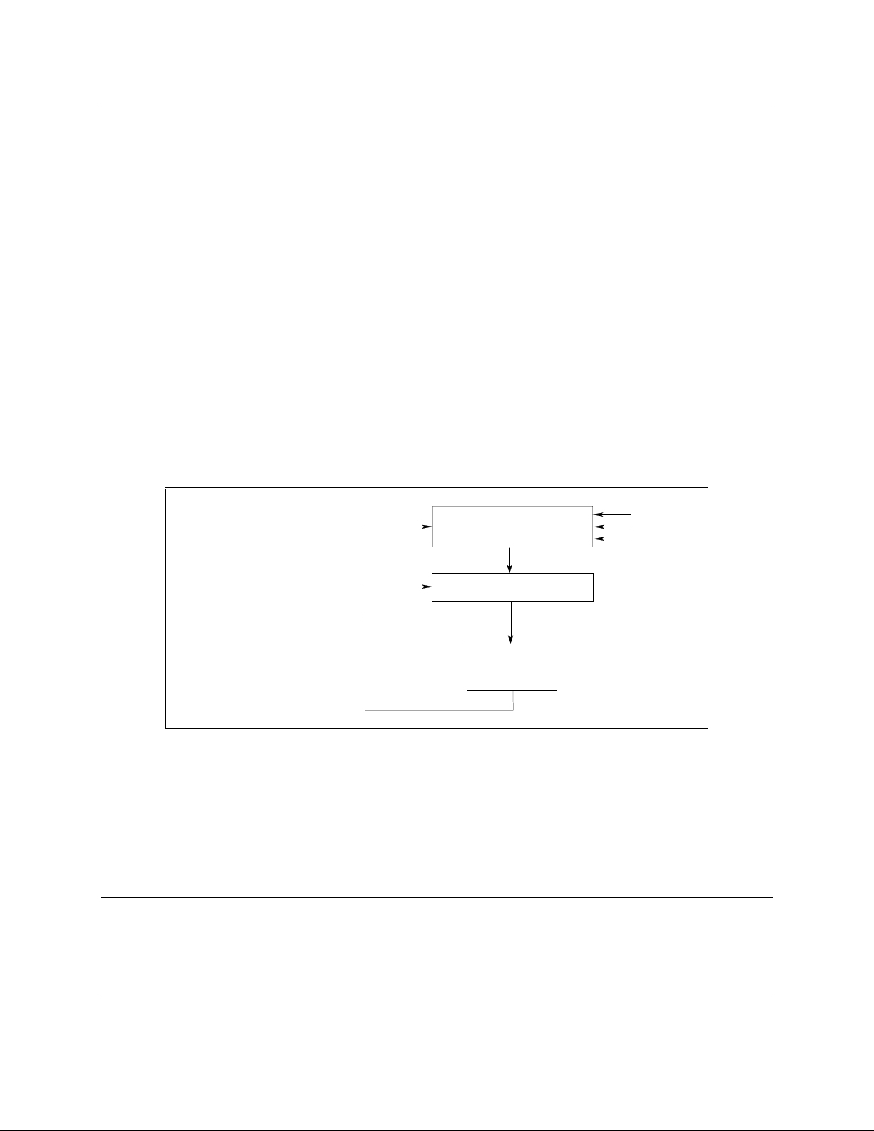
INITIATED STATE
IDLE STATE
TRIGGER RECEIVED
INITiate[:IMMediate]
Triggering Output Changes
The dc source has two independent trigger systems. One is used for generating output changes, and the
other is used for triggering measurements. This section describes the output trigger system. The
measurement trigger system is described under "Triggering Measurements".
SCPI Triggering Nomenclature
In SCPI terms, trigger systems are called sequences. When more than one trigger system exists, they are
differentiated by naming them SEQuence1 and SEQuence2. SEQuence1 is the transient trigger system
and SEQuence2 is the measurement trigger system. The dc source uses aliases with more descriptive
names for these sequences. These aliases can be used instead of the sequence forms.
Sequence Form Alias
SEQuence1 TRANsient
SEQuence2 ACQuire
Output Trigger System Model
Figure 3-1 is a model of the output trigger system. The rectangular boxes represent states. The arrows
show the transitions between states. These are labeled with the input or event that causes the transition
to occur.
ABORt
INITiate:CONTinuous OFF
INITiate:CONTinuous ON
OUTPUT
LEVEL
CHANGE
*RST
*RCL
Figure 3-1. Model of Output Triggers
Setting the Voltage or Current Trigger Levels
To program output trigger levels, you must first specify a voltage or current trigger level that the output will
go to once a trigger signal is received. Use the following commands to set the output trigger level:
VOLTage:TRIGgered <n> or
CURRent:TRIGgered <n>
NOTE: Until they are programmed, uninitialized trigger levels will assume their corresponding
immediate levels. For example, if a dc source is powered up and VOLTage:LEVel is
programmed to 6, then VOLTage:LEVel:TRIGger will also be 6 until you program it to
another value. Once you program VOLTage:LEVel:TRIGger to a value, it will remain at
that value regardless of how you subsequently reprogram VOLTage:LEVel.
21
Page 22

3 - Programming the DC Source
Initiating the Output Trigger System
When the dc source is turned on, the trigger subsystem is in the idle state. In this state, the trigger
subsystem ignores all triggers. Sending the following commands at any time returns the trigger system to
the Idle state:
ABORt
*RST
*RCL
The INITiate commands move the trigger system from the Idle state to the Initiated state. This enables
the dc source to receive triggers. To initiate for a single triggered action, use:
INITiate:SEQuence1or
INITiate:NAME TRANsient
After a trigger is received and the action completes, the trigger system will return to the Idle state. Thus it
will be necessary to initiate the system each time a triggered action is desired.
To keep a trigger system initiated for multiple actions without having to send an initiate command for each
trigger, use:
INITiate:CONTinuous:SEQuence1 ON or
INITiate:CONTinuous:NAME TRANsient, ON
Generating Triggers
You can only program output triggers over the GPIB bus. Since BUS is the only trigger source for output
triggers, the following command is provided for completeness only:
TRIGger:SOURce BUS
After you have specified the appropriate trigger source, you can generate triggers as follows:
Single Triggers Send one of the following commands over the GPIB:
TRIGger:IMMediate
*TRG
a group execute trigger
Continuous Triggers Send the following command over the GPIB:
INITiate:CONTinuous:SEQuence1 ON
When the trigger system enters the Output Change state upon receipt of a trigger (see figure 3-1), the
triggered functions are set to their programmed trigger levels. When the triggered actions are completed,
the trigger system returns to the Idle state.
22
Page 23

Programming the DC Source - 3
Making Measurements
The dc source has the ability to make several types of voltage or current measurements. The
measurement capabilities of the Agilent 66312A and Agilent 66332A models are particulary useful for
loads that draw current in pulses.
NOTE: You cannot measure output voltage and current simultaneously.
All measurements are performed by digitizing the instantaneous output voltage or current for a defined
number of samples and sample interval, storing the results in a buffer, and then calculating the measured
result. Many parameters of the measurement are programmable. These include the number of samples,
the time interval between samples, the bandwidth, and the method of triggering. Note that there is a
tradeoff between these parameters and the speed, accuracy, and stability of the measurement in the
presence of noise.
There are two ways to make measurements:
♦
Use the MEASure commands to immediately start acquiring new voltage or current data, and
return measurement calculations from this data as soon as the buffer is full. This is the easiest
way to make measurements, since it requires no explicit trigger programming.
♦
Use an acquisition trigger to acquire the data. Then use the FETCh commands to return
calculations from the data that was retrieved by the acquisition trigger. This method gives you the
flexibility to synchronize the data acquisition with a transition in the output voltage or current.
FETCh commands do not trigger the acquisition of new measurement data, but they can be used
to return many different calculations from the data that was retrieved by the acquisition trigger.
Note that if you take a voltage measurement, you can fetch only voltage data.
Making triggered measurements with the acquisition trigger system is discussed under "Triggering
Measurements".
NOTE: For each MEASure form of the query, there is a corresponding query that begins with the
header FETCh. FETCh queries perform the same calculation as their MEASure
counterparts, but do not cause new data to be acquired. Data acquired by an explicit
trigger or a previously programmed MEASure command are used.
Voltage and Current Measurements
The SCPI language provides a number of MEASure and FETCh queries which return various
measurement parameters of voltage and current waveforms.
DC Measurements
To measure the dc output voltage or current, use:
MEASure:VOLTage? or
MEASure:CURRent?
Dc voltage and current is measured by acquiring a number of readings at the selected time interval,
applying a Hanning window function to the readings, and averaging the readings. Windowing is a signal
conditioning process that reduces the error in dc measurements made in the presence of periodic signals
such as line ripple. At power-on and after a *RST command, the following parameters are set:
SENSe:SWEep:TINTerval 15.6E-6
SENSe:SWEep:POINts 2048
23
Page 24

3 - Programming the DC Source
This results in a data acquisition time of 32 milliseconds. Adding a command processing overhead of
about 20 milliseconds results in a total measurement time of about 50 milliseconds per measurement
sample.
Ripple rejection is a function of the number of cycles of the ripple frequency contained in the acquisition
window. More cycles in the aquisition window results in better ripple rejection. If you increase the time
interval for each measurement to 45 microseconds for example, this results in 5.53 cycles in the
acquisition window at 60 Hz, for a ripple rejection of about 70 dB.
Note that the speed of the measurement can be increased by reducing the number of sample points. For
example, the commands
SENSe:SWEep:TINTerval 15E-6
SENSe:SWEep:POINts 1024
speeds up the acquisition period to 16 milliseconds; however, the tradeoff is reduced measurement
accuracy.
RMS Measurements (Agilent 66312A, 66332A Only)
To read the rms content of a voltage or current waveform, use:
MEASure:VOLTage:ACDC? or
MEASure:CURRent:ACDC?
This returns the total rms measurement, including the dc portion.
Making rms measurements on ac waveforms for which a non-integral number of cycles of data has been
acquired may result in measurement errors due to the last partial cycle of acquired data. The instrument
reduces this error by using a Hanning window function when making the measurement.
Minimum and Maximum Measurements (Agilent 66312A, 66332A Only)
To measure the maximum or minimum voltage or current of a pulse or ac waveform, use:
MEASure:VOLTage:MAXimum?
MEASure:VOLTage:MINimum?
MEASure:CURRent:MAXimum?
MEASure:CURRent:MINimum?
Current Ranges
The dc source has two current measurement ranges. The command that controls the ranges is:
SENSe:CURRent:RANGe MIN | MAX
When the range is set to MIN, the maximum current that can be measured is 20 milliamperes.
Returning Measurement Data From the Data Buffer (Agilent 66312A, 66332A Only)
The MEASure and FETCh queries can also return all data values of the instantaneous voltage or current
buffer. The commands are:
MEASure:ARRay:CURRent?
MEASure:ARRay:VOLTage?
24
Page 25
Programming the DC Source - 3
[
]
Internally Triggered Measurements
You can use the data acquisition trigger system to synchronize the timing of the voltage and current data
acquisition with a BUS or internal trigger source. Then use the FETCh commands to return different
calculations from the data acquired by the measurement trigger.
SCPI Triggering Nomenclature
As previously explained under "Triggering Output Changes", the dc source uses the following sequence
name and alias for the measurement trigger system. This alias can be used instead of the sequence form.
Sequence Form Alias
SEQuence2 ACQuire
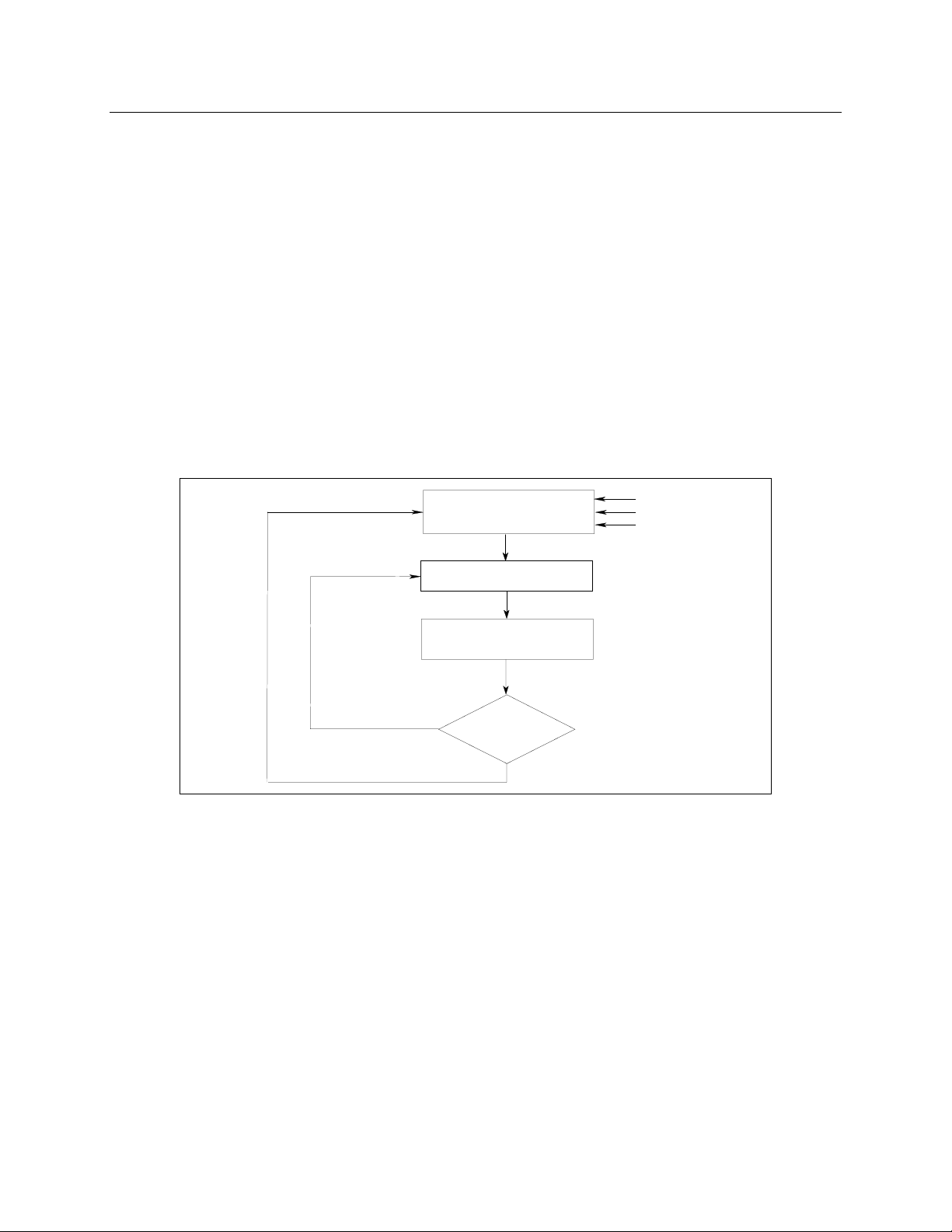
Measurement Trigger System Model
Figure 3-2 is a model of the measurement trigger system. The rectangular boxes represent states. The
arrows show the transitions between states. These are labeled with the input or event that causes the
transition to occur.
IDLE STATE
INITIATED STATE
SENSe:SWEep:POINts
ACQUIRED
NO
TRIGger:COUNt
COMPLETE?
YES
INITiate
:IMMediate
TRIGGER RECEIVED
ABORt
*RST
*RCL
Figure 3-2. Model of Measurement Triggers
Initiating the Measurement Trigger System (Agilent 66312A, 66332A Only)
When the dc source is turned on, the trigger system is in the idle state. In this state, the trigger system
ignores all triggers. Sending the following commands at any time returns the trigger system to the Idle
state:
ABORt
*RST
*RCL
The INITiate commands move the trigger system from the Idle state to the Initiated state. This enables
the dc source to receive triggers. To initiate for a measurement trigger, use:
25
Page 26

3 - Programming the DC Source
INITiate:SEQuence2 or
INITiate:NAME ACQuire
After a trigger is received and the data acquisition completes, the trigger system will return to the Idle state
(unless multiple measurements are desired). Thus it will be necessary to initiate the system each time a
triggered acquisition is desired.
NOTE: You cannot initiate measurement triggers continuously. Otherwise, the measurement data
in the data buffer would continuously be overwritten by each triggered measurement.
Selecting the Measurement Trigger Source (Agilent 66312A, 66332A Only)
The trigger system is waiting for a trigger signal in the Initiated state. Before you generate a trigger, you
must select a trigger source. The following measurement trigger sources can be selected:
BUS - selects GPIB bus triggers.
INTernal - selects the dc source’s output as the measurement trigger.
To select GPIB bus triggers (group execute trigger, device trigger, or *TRG command), use:
TRIGger:SEQuence2:SOURce BUS or
TRIGger:ACQuire:SOURce BUS
To select internal triggers (measurements triggered off the output signal) use:
TRIGger:SEQuence2:SOURce INTernal or
TRIGger:ACQuire:SOURce INTernal
Generating Measurement Triggers (Agilent 66312A, 66332A Only)
There is only one measurement converter in the dc source. Before you generate a measurement trigger,
you must specify a measurement acquistion of either voltage or current. To specify a measurement
acquisition use:
SENSe:FUNCtion "CURRent" or
SENSe:FUNCtion "VOLTage"
Providing that you have specified the appropriate trigger source and a measurement acquisition, you can
generate triggers as follows:
GPIB Triggers Send one of the following commands over the GPIB:
TRIGger:IMMediate (not affected by the trigger source setting)
*TRG
a group execute trigger
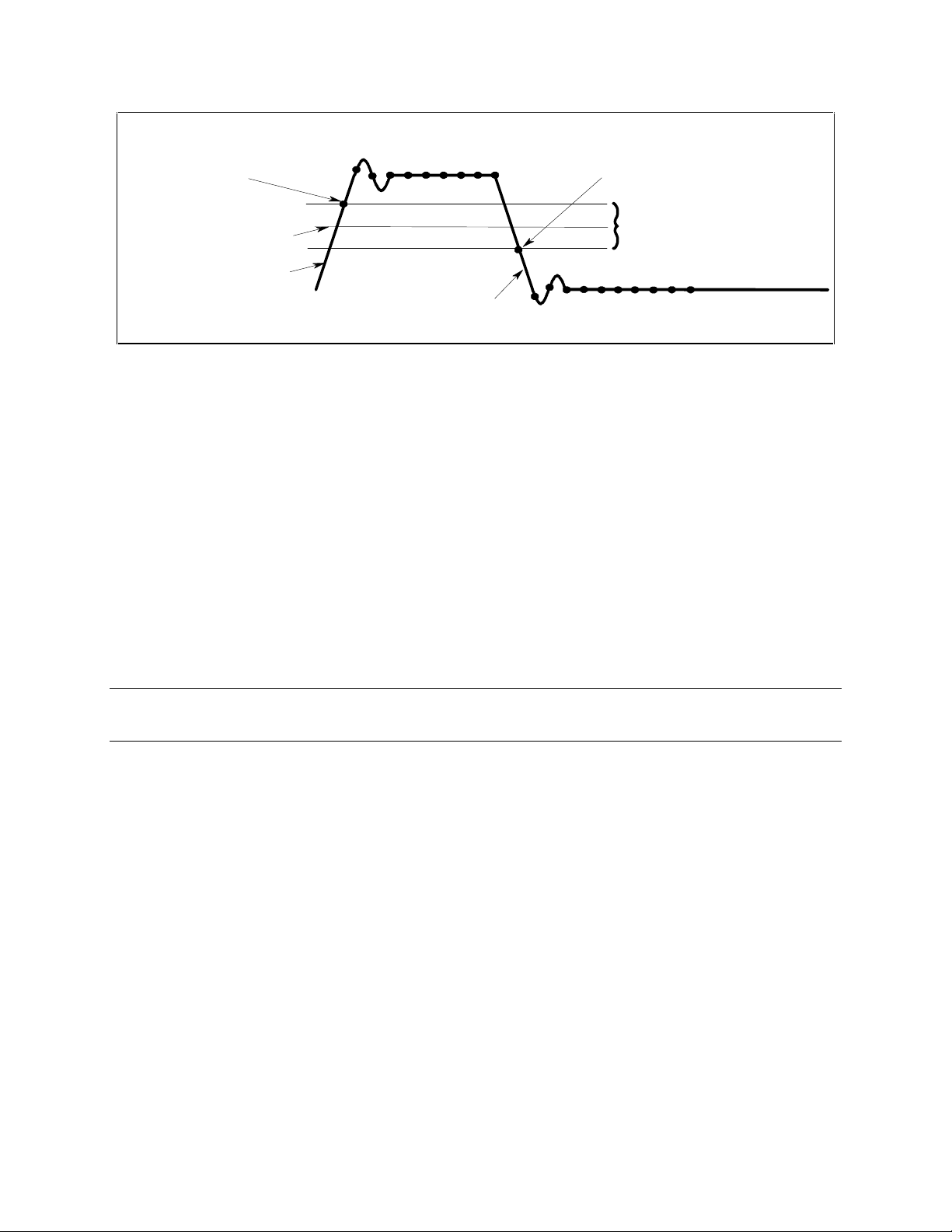
Internal Triggers To trigger off of the output signal, you must specify the output level that generates
the trigger, the rising or falling edge of the slope, and a hysteresis to qualify trigger
conditions. This is illustrated in figure 3-3.
26
Page 27
Q
>
TRIG:ACQ:HYST:CURR <value>
Trigger occurs on rising edge
g
TRIG :AC Q :HYST:V O LT
Trigger occu rs on falling edg e
when signal crosses negative
nal crosses positive
when si
hysteresis band limit
Programming the DC Source - 3
hysteresis band limit
TRIG:A C
TRIG:ACQ:LEV:VOLT
TRIG:ACQ:SLOP:CURR
TRIG:ACQ:SLOP:VOLT
:LEV:CURR <level
TRIG:ACQ:SLOP:CURR NEG
TRIG:ACQ:SLOP:VOLT
Figure 3-3. Trigger Commands Used to Measure Output Pulses
To specify the output level that will generate triggers for both positive- and negative-going signals use:
TRIGger:SEQuence2:LEVel:CURRent <value> or
TRIGger:ACQuire:LEVel:CURRent <value>
To specify the slope on which triggering occurs use the following commands. You can specify a POSitive,
a NEGative, or EITHer type of slope.
TRIGger:SEQuence2:SLOPe:CURRent <slope> or
TRIGger:ACQuire:SLOPe:CURRent <slope>
To specify a hysteresis band to qualify the positive- or negative-going signal use:
TRIGger:SEQuence2:HYSTeresis:CURRent <value> or
TRIGger:ACQuire:HYSTeresis:CURRent <value>
NOTE: When using internal triggers, do not INITiate the measurement until after you have
specified the slope, level, and hysteresis.
When the acquisition finishes, any of the FETCh queries can be used to return the results. Once the
measurement trigger is initiated, if a FETCh query is sent before the data acquisition is triggered or before
it is finished, the response data will be delayed until the trigger occurs and the acquisition completes. This
may tie up the controller if the trigger condition does not occur immediately.
One way to wait for results without tying up the controller is to use the SCPI command completion
commands. For example, you can send the *OPC command after INITialize, then occasionally poll the
OPC status bit in the standard event status register for status completion while doing other tasks. You can
also set up an SRQ condition on the OPC status bit going true, and do other tasks until an SRQ interrupt
occurs.
27
Page 28
3 - Programming the DC Source
Measuring Output Pulses (Agilent 66312A, 66332A Only)
Current Detector
Check that the current detector is set to ACDC when measuring current pulses or other waveforms with a
frequency content greater than a few kilohertz.
SENSe:CURRent:DETect ACDC
Only select DC as the measurement detector if you are making only DC current measurements and you
require a measurement offset better than 2mA on the High current measurement range. Note that this
selection gives inaccurate results on current waveforms that have ac content.
SENSe:CURRent:DETect DC
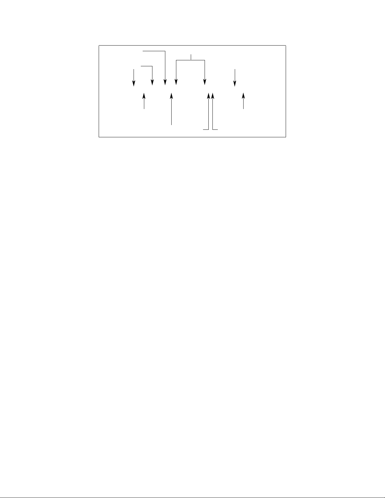
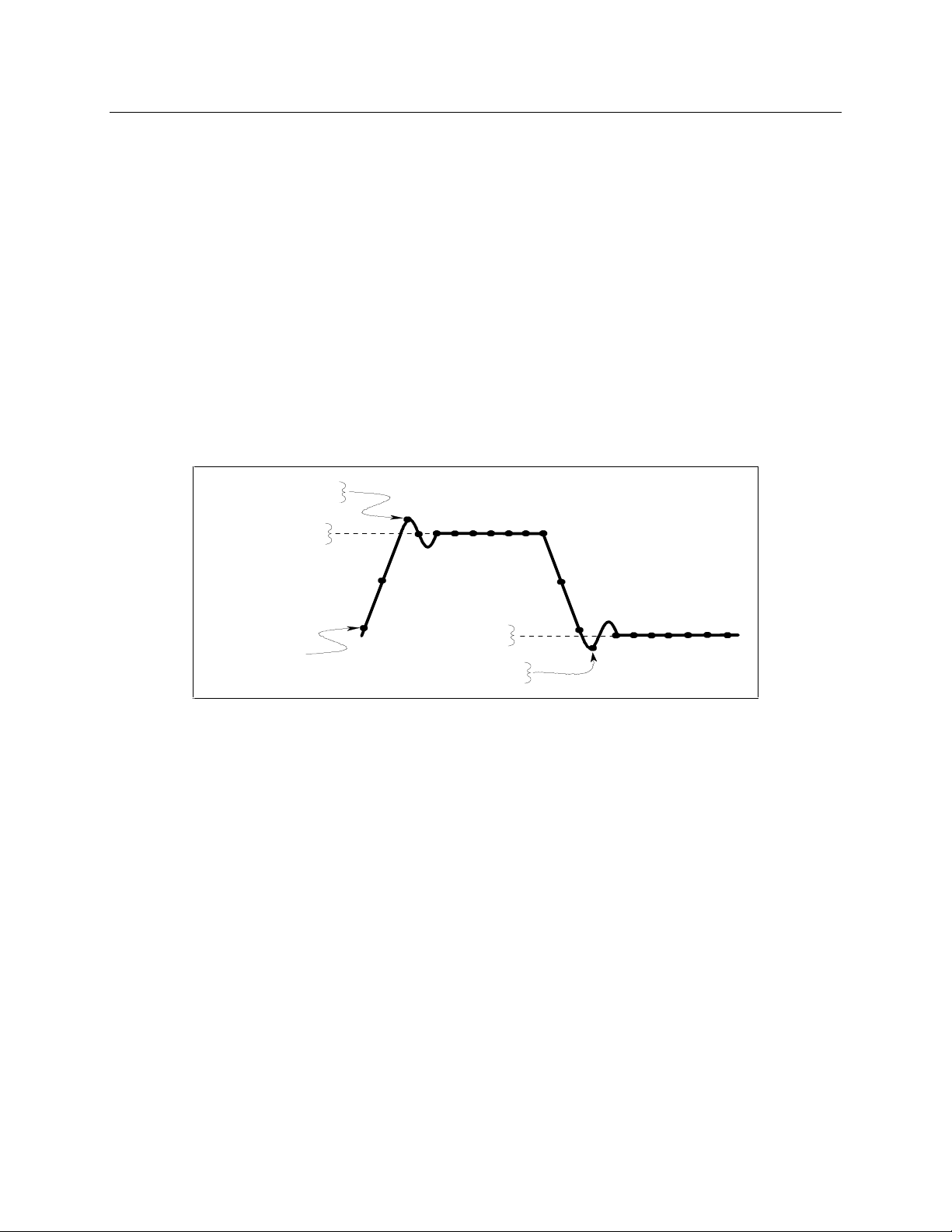
Pulse Measurement Queries
The dc source has several measurement queries that return key parameters of pulsewaveforms as shown
in Figure 3-4.
FETC:CURR:MAX?
FETC:VOLT:MAX?
FETC:CURR:HIGH?
FETC:VOLT:HIGH?
FETC:CURR:LOW?
DATA POINTS
FETC:VOLT:LOW?
FETC:CURR:MIN?
FETC:VOLT:MIN?
Figure 3-4. Measurement Commands Used to Return Pulse Data
To return the maximum or minimum value of a pulse waveform use the following commands. Note that
the data points of the measurement sample may not coincide with the actual maximum or minimum point
on the waveform.
FETCh:VOLTage:MAXimum? or
FETCh:VOLTage:MINimum?
FETCh:CURRent:MAXimum? or
FETCh:CURRent:MINimum?
The average value of the high level or low level of a pulse can also be measured. To return the average
value of the high level, use:
FETCh:CURRent:HIGH? or
FETCh:VOLTage:HIGH?
To return the average value of the low level, use:
FETCh:CURRent:LOW? or
FETCh:VOLTage:LOW?
28
Page 29
Programming the DC Source - 3
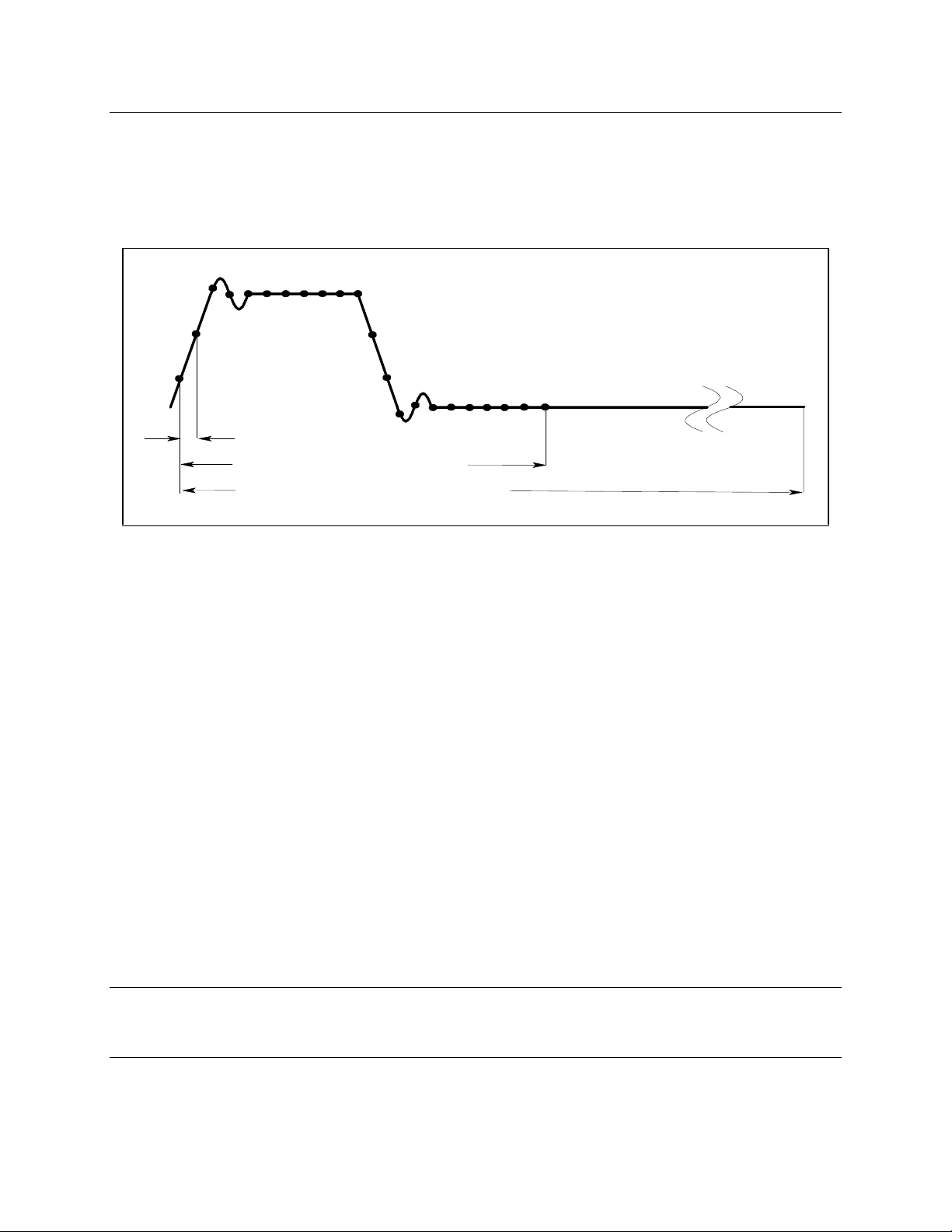
Controlling Measurement Samples
Varying the Voltage or Current Sampling Rate
You can vary both the number of data points in a measurement sample, as well as the time between
samples. This is illustrated in Figure 3-5.
<
p
>
<
p
>
Figure 3-5. Sense Commands Used to Vary the Sampling Rate
At *RST, the output voltage or current sampling rate is 15.6 microseconds. This means that it takes about
32 milliseconds to fill up 2048 data points in the data buffer. You can vary this data sampling rate with:
SENSe:SWEep:TINTerval <sample_period>
SENSe:SWEep:POINts <points>
For example, to set the time interval to 46.8 microseconds per sample with 1500 samples, use
SENSe:SWEep:TINTerval 46.8E-6;POINts 1500.
Multiple Measurements (Agilent 66312A, 66332A Only)
The instrument also has the ability to set up several acquisition triggers in succession and average the
results from each acquisition in the returned measurement. To set up the trigger system for a number of
sequential aquisitions use:
TRIGger:ACQuire:COUNt:CURRent <number> or
TRIGger:ACQuire:COUNt:VOLTage <number>
With this setup, the instrument performs each acquisition sequentially, storing the digitized readings in the
internal measurement buffer. It is only necessary to initialize the measurement once at the start; after
each completed aquisition the instrument will wait for the next valid trigger condition to start another. The
results returned by MEASure or FETCh will be the average of the total data acquired.
NOTE: The total number of data points cannot exceed 4096. This means that the product of the
trigger count multiplied by the sweep points cannot exceed 4096; otherwise an error will
occur.
29
Page 30
3 - Programming the DC Source
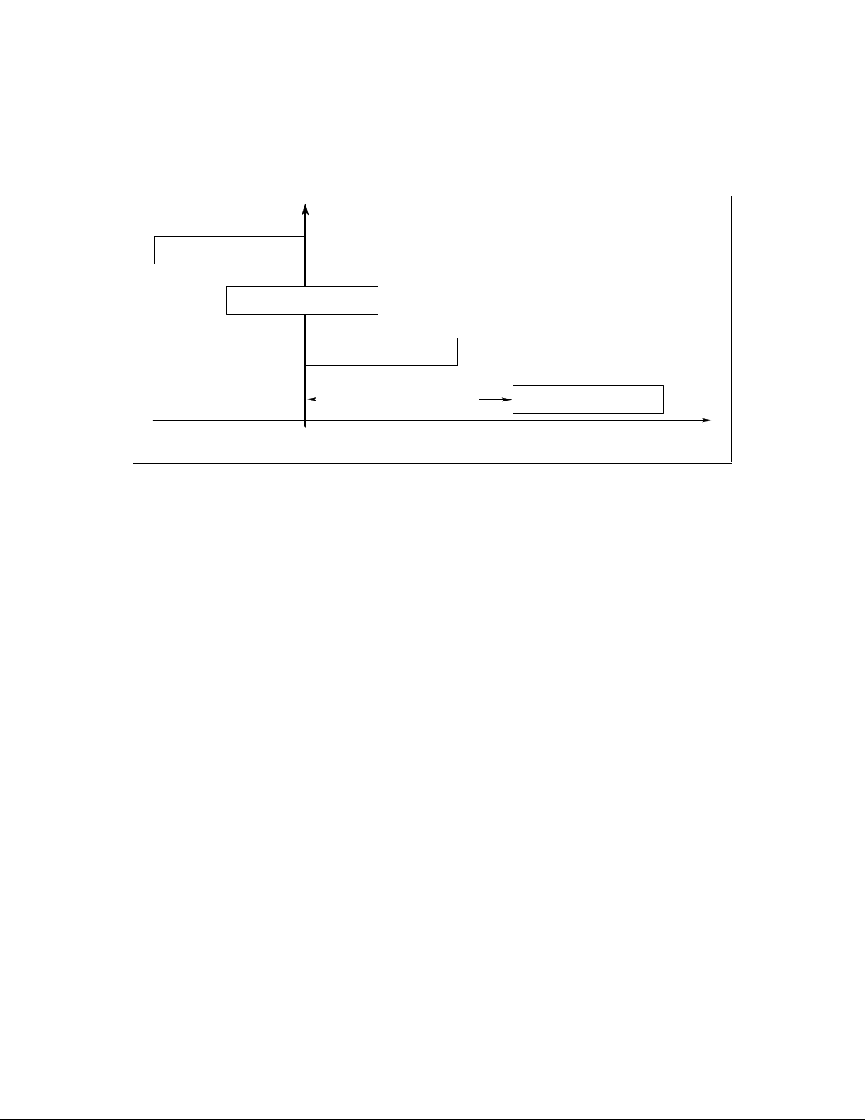
Pre-event and Post-event Triggering (Agilent 66312A, 66332A Only)
When a measurement is initiated, the dc source continuously samples either the instantaneous output
voltage or current. As shown in figure 3-6, you can move the block of data being read into the acquisition
buffer with reference to the acquisition trigger. This permits pre-event or post-event data sampling.
=-
=-
=
=
Figure 3-6. Pre-event and Post-event Triggering
To offset the beginning of the acquisition buffer relative to the acquisition trigger, use:
SENSe:SWEep:OFFSet:POINts <offset>
The range for the offset is -4096 to 2,000,000,000 points. As shown in the figure, when the offset is
negative, the values at the beginning of the data record represent samples taken prior to the trigger. When
the value is 0, all of the values are taken after the trigger. Values greater than zero can be used to
program a delay time from the receipt of the trigger until the data points that are entered into the buffer are
valid. (Delay time = Offset X Sample period)
Pulse Measurement Example (Agilent 66312A, 66332A only)
The following program illustrates how to make a pulse measurement over the GPIB. The measurement
function is set to ACDC, which gives the best results for current waveforms that have ac content. The
measurement incorporates 100 readings taken at time intervals of 20 microseconds, for a total
measurement time of 2 milliseconds. The trigger point for the pulse measurement occurs at 0.1 amperes
on the positive slope of the current pulse. The measurement offset is programmed so that 20
measurement points prior to the trigger are also returned as part of the measurement sample.
Because measurement triggers are initiated by the current pulse, a FETCh command is used to return the
measurement data. FETCh commands are also used to return the MAXimum, MINimum, HIGH, and LOW
values of the measurement.
NOTE: MEASure commands cannot be used to return data in this example because they always
acquire NEW measurement data each time they are used.
The program can be run on any controller operating under Agilent BASIC. To generate output pulses, an
electronic load is programmed to generate 3-ampere pulses with a duty cycle of 100 microseconds at
1000 Hz. The power supply address is 705, and the load address is 706. If required, change these
parameters in the appropriate statements.
30
Page 31

Programming the DC Source - 3
10 !Rev A.00.00
20 OPTION BASE 1
30 DIM Curr_array(100)
40 !
50 ASSIGN @Ps TO 705
60 ASSIGN @Ld TO 706
80 OUTPUT @Ps;"*RST" ! Sets supply to default values
90 OUTPUT @Ps;"OUTP ON" ! Turn on power supply output
100 OUTPUT @Ps;"VOLT 5;CURR 5" ! Program power supply to 5 volts, 5 amps
110 !
120 OUTPUT @Ld;"CURR:LEVEL 0" ! Set up electronic load to produce pulses
130 OUTPUT @Ld;"CURR:TLEVEL 3"
140 !
150 OUTPUT @Ld;"TRAN:FREQ 1000"
160 OUTPUT @Ld;"TRAN:DCYCLE 10"
170 OUTPUT @Ld;"TRAN:MODE CONT"
180 OUTPUT @Ld;"TRAN:STATE ON"
190 !
200 OUTPUT @Ps;"SENS:CURR:DET ACDC" ! Set meter to ACDC
210 OUTPUT @Ps;"SENS:CURR:RANG MAX" ! High Current range
220 OUTPUT @Ps;"TRIG:ACQ:SOUR INT" ! Set to trigger on pulse
230 OUTPUT @Ps;"SENS:FUNC ""CURR""" ! Acquire current reading
240 OUTPUT @Ps;"TRIG:ACQ:LEV:CURR .1" ! Trigger at 0.1 amps
250 OUTPUT @Ps;"TRIG:ACQ:SLOPE:CURR POS" ! Trigger on positive slope
260 OUTPUT @Ps;"TRIG:ACQ:HYST:CURR .05" ! Set hysteresis of trigger
270 OUTPUT @Ps;"SENS:SWE:TINT 20E-6" ! Set sample time interval to 20us
280 OUTPUT @Ps;"SENS:SWE:POIN 100" ! Set number of measurement samples in sweep
290 OUTPUT 705;"SENS:SWE:OFFS:POIN -20" ! Number of sample points before trigger
300 OUTPUT @Ps;"INIT:NAME ACQ" ! Initiate the trigger system.
310 ! Controller now waits for trigger to occur.
320 OUTPUT @Ps;"FETCH:ARRAY:CURR?" ! Get the data after measurement completes.
330 !
340 ENTER @Ps;Curr_array(*) ! Enters all 100 data points
350 PRINT Curr_array(*) ! Print all data points
360 !
370 OUTPUT @Ps;"FETCH:CURR:MAX?" ! Get more data from previous measurement.
380 ENTER @Ps;Curr_max
390 PRINT "MAX CURRENT",Curr_max
400 !
410 OUTPUT @Ps;"FETCH:CURR:MIN?"
420 ENTER @Ps;Curr_min
430 PRINT "MIN CURRENT",Curr_min
440 !
450 OUTPUT @Ps;"FETCH:CURR:HIGH?"
460 ENTER @Ps;Curr_hi
470 PRINT "HIGH CURRENT",Curr_hi
480 !
490 OUTPUT @Ps;"FETCH:CURR:LOW?"
500 ENTER @Ps;Curr_low
510 PRINT "LOW CURRENT",Curr_low
520 !
530 END
When this program runs, it returns 100 measurement data points as well as the MIN, MAX, HIGH, and
LOW data in the following format:
.030585 .031869 .0344369 .031655 .0320829 .0325109 .0333669 .0340089
.0320825 .031449 .031227 .031441 .0337949 .0327249 .031869 .031655
.0327249 .031013 .0325109 .0333669 3.09751 3.1814 3.14266 3.13667
3.13817 3.13624 .977283 .0667496 .0245932 .0280171 .031013 .031655
.0331529 .0350788 .0348648 .0327249 .031227 .0327249 .031227 .030799
.031869 .0329389 .030371 .031655 .031869 .0329389 .031869 .0322869
.0320829 .0325109 .0333669 .0340089 .0348648 .0327249 .031227 .0327249
.0320829 .030371 .031449 .031227 .031441 .0337949 .031449 .0333669
.031441 .0337949 .030371 .031655 .031869 .0329389 .031869 .0293011
.031441 .0337949 .0327249 .031869 .031655 .031655 .0320829 .031227
.0322969 .031655 .0327249 .0340089 2.97661 3.18632 3.14523 3.13496
3.13453 3.13731 1.32438 .0836549 .0258772 .0284451 .0275891 .0329389
.0329389 .0333669 .0322969 .0333669
MAX CURRENT 3.18632
MIN CURRENT .0245932
HIGH CURRENT 3.1371
LOW CURRENT .0314077
31
Page 32

3 - Programming the DC Source
Programming the Status Registers
You can use status register programming to determine the operating condition of the dc source at any
time. For example, you may program the dc source to generate an interrupt (assert SRQ) when an event
such as a current limit occurs. When the interrupt occurs, your program can then act on the event in the
appropriate fashion.
Figure 3-7 shows the status register structure of the dc source. Table 3-1 defines the status bits. The
Standard Event, Status Byte, and Service Request Enable registers and the Output Queue perform
standard GPIB functions as defined in the
Instrumentation
. The Operation Status and Questionable Status registers implement functions that are
specific to the dc source.
Power-On Conditions
Refer to the *RST command description in chapter 4 for the power-on conditions of the status registers.
QUESTIONABLE STATUS
OCP
N.U.
N.U.
Unreg
N.U.
MeasOvld
N.U.
OPC
N.U.
QYE
DDE
EXE
CME
N.U.
PON
CONDITION
0
OV
1
2
FS
3
4
OT
5-8
9
RI
10
1024
11-13
14
15
STANDARD EVENT STATUS
EVENT ENABLE
0
1
2
3
4
5
6
7
1
2
4
16
512
1
4
8
16
32
128
PTR/NTR
1
2
444
16
512
1024
16384 16384 1638416384
1
4
8
16
32
128
EVENT
1
2
16
512
1024
LOGICAL OR
IEEE 488.2 Standard Digital Interface for Programmable
ENABLE
1
2
16
512
1024
OUTPUT QUEUE
DATA
DATA
DATA
LOGICAL OR
QUEUE
NOT
EMPTY
OFF
N.U.
QUES
MAV
ESB
MSS
OPER
OUTPut:DFI:SOURce
STATUS BYTE
0-2
3
4
5
6
7
8
16
32
64
128
SERVICE
REQUEST
ENABLE
FLT
8
16
32
128
LOGICAL OR
CAL
N.U.
WTG
N.U.
CV
N.U.
CC+
CCN.U.
32
0
1-4
5
6,7
8
9
10
11
12-15
CONDITION
1
32
256
512
1024
2048
OPERATIO N STATUS
PTR/NTR
1
32
256
512
1024
2048
EVENT
1
32
256
512
1024
2048
ENABLE
1
32
256
512
1024
2048
LOGICAL OR
Figure 3-7. DC Source Status Model
RQS
SERVICE
REQUEST
GENERATION
),**$/
Page 33

Table 3-1. Bit Configurations of Status Registers
Bit Signal Meaning
0
5
8
10
11
0
1
2
4
9
10
14
0
2
3
4
5
7
3
4
5
6
7
CAL
WTG
CV
CC+
CC-
OV
OCP
FS
OT
RI
Unreg
MeasOvld
OPC
QYE
DDE
EXE
CME
PON
QUES
MAV
ESB
MSS
RQS
OPER
Operation Status Group
The dc source is computing new calibration constants
The dc source is waiting for a trigger
The dc source is in constant voltage mode
The dc source is in constant current mode
The dc source is in negative constant current mode
Questionable Status Group
The overvoltage protection has tripped
The overcurrent protection has tripped
The fuse is blown
The overtemperature protection has tripped
The remote inhibit state is active
The output is unregulated
Current measurement exceeded capability of low range
Standard Event Status Group
Operation complete
Query error
Device-dependent error
Execution error
Command error
Power-on
Status Byte and Service Request Enable Registers
Questionable status summary bit
Message Available summary bit
Event Status Summary bit
Master Status Summary bit
Request Service bit
Operation status summary bit
Programming the DC Source - 3
Operation Status Group
The Operation Status registers record signals that occur during normal operation. As shown below, the
group consists of a Condition, PTR/NTR, Event, and Enable register. The outputs of the Operation Status
register group are logically-ORed into the OPER(ation) summary bit (7) of the Status Byte register.
Register Command Description
Condition
PTR Filter
NTR Filter
Event
Enable
STAT:OPER:COND?
STAT:OPER:PTR <n>
STAT:OPER:NTR <n>
STAT:OPER:EVEN?
STAT:OPER:ENAB <n>
A register that holds real-time status of the circuits being
monitored. It is a read-only register.
A positive transistion filter that functions as described under
STAT:OPER:NTR|PTR commands in chapter 4. It is a
read/write register.
A negative transition filter that functions as described under
STAT:OPER:NTR|PTR commands in chapter 4. It is a
read/write register.
A register that latches any condition that is passed through the
PTR or NTR filters. It is a read-only register that is cleared
when read.
A register that functions as a mask for enabling specific bits
from the Event register. It is a read/write register.
33
Page 34

3 - Programming the DC Source
Questionable Status Group
The Questionable Status registers record signals that indicate abnormal operation of the dc source. As
shown in figure 3-7, the group consists of the same type of registers as the Status Operation group. The
outputs of the Questionable Status group are logically-ORed into the QUEStionable summary bit (3) of the
Status Byte register.
Register Command Description
Condition STAT:QUES:COND? A register that holds real-time status of the circuits being
monitored. It is a read-only register.
PTR Filter STAT:QUES:PTR <n> A positive transistion filter that functions as described under
STAT:QUES:NTR|PTR commands in chapter 4. It is a
read/write register.
NTR Filter STAT:QUES:NTR <n> A negative transition filter that functions as described under
STAT:QUES:NTR|PTR commands in chapter 4. It is a
read/write register.
Event STAT:QUES:EVEN? A register that latches any condition that is passed through the
PTR or NTR filters. It is a read-only register that is cleared
when read.
Enable STAT:QUES:ENAB <n> A register that functions as a mask for enabling specific bits
from the Event register. It is a read/write register..
Standard Event Status Group
This group consists of an Event register and an Enable register that are programmed by Common
commands. The Standard Event event register latches events relating to instrument communication status
(see figure 3-7). It is a read-only register that is cleared when read. The Standard Event enable register
functions similarly to the enable registers of the Operation and Questionable status groups.
Command Action
*ESE
*PSC ON
*ESR?
The PON (Power On) Bit
The PON bit in the Standard Event event register is set whenever the dc source is turned on. The most
common use for PON is to generate an SRQ at power-on following an unexpected loss of power. To do
this, bit 7 of the Standard Event enable register must be set so that a power-on event registers in the ESB
(Standard Event Summary Bit), bit 5 of the Service Request Enable register must be set to permit an SRQ
to be generated, and *PSC OFF must be sent. The commands to accomplish these conditions are:
*PSC OFF *ESE 128 *SRE 32
programs specific bits in the Standard Event enable register.
clears the Standard Event enable register at power-on.
reads and clears the Standard Event event register.
Status Byte Register
This register summarizes the information from all other status groups as defined in the
Standard Digital Interface for Programmable Instrumentation
Command Action
*STB? reads the data in the register but does not clear it (returns MSS in bit 6)
serial poll clears RQS inside the register and returns it in bit position 6 of the response.
. The bit configuration is shown in Table 3-1.
IEEE 488.2
34
Page 35

Programming the DC Source - 3
The MSS Bit
This is a real-time (unlatched) summary of all Status Byte register bits that are enabled by the Service
Request Enable register. MSS is set whenever the dc source has one or more reasons for requesting
service. *STB? reads the MSS in bit position 6 of the response but does not clear any of the bits in the
Status Byte register.
The RQS Bit
The RQS bit is a latched version of the MSS bit. Whenever the dc source requests service, it sets the
SRQ interrupt line true and latches RQS into bit 6 of the Status Byte register. When the controller does a
serial poll, RQS is cleared inside the register and returned in bit position 6 of the response. The remaining
bits of the Status Byte register are not disturbed.
The MAV Bit and Output Queue
The Output Queue is a first-in, first-out (FIFO) data register that stores dc source-to-controller messages
until the controller reads them. Whenever the queue holds one or more bytes, it sets the MAV bit (4) of the
Status Byte register.
Determining the Cause of a Service Interrupt
You can determine the reason for an SRQ by the following actions:
Step 1 Determine which summary bits are active. Use:
*STB? or serial poll
Step 2
Step 3 Remove the specific condition that caused the event. If this is not possible, the event
Read the corresponding Event register for each summary bit to determine which events
caused the summary bit to be set. Use:
STATus:QUEStionable:EVENt?
STATus:OPERation:EVENt?
ESR?
When an Event register is read, it is cleared. This also clears the corresponding
summary bit.
may be disabled by programming the corresponding bit of the status group Enable
register or NTR|PTR filter. A faster way to prevent the interrupt is to disable the service
request by programming the appropriate bit of the Service Request Enable register
Servicing Operation Status and Questionable Status Events
This example assumes you want a service request generated whenever the dc source switches to the CC
(constant current) operating mode, or whenever the dc source’s overvoltage, overcurrent, or
overtemperature circuits have tripped. From figure 3-7, note the required path for a condition at bit 10
(CC) of the Operation Status register to set bit 6 (RQS) of the Status Byte register. Also note the required
path for Questionable Status conditions at bits 0, 1, and 4 to generate a service request (RQS) at the
Status Byte register. The required register programming is as follows:
Step 1 Program the Operation Status PTR register to allow a positive transition at bit 10 to be
latched into the Operation Status Event register, and allow the latched event to be
summed into the Operation summary bit. Use:
STATus:OPERation:PTR 1024;ENABle 1024
Step 2
Program the Questionable Status PTR register to allow a positive transition at bits 0,
1, or 4 to be latched into the Questionable Status Event register, and allow the latched
35
Page 36

3 - Programming the DC Source
event to be summed into the Questionable summary bit. Use:
STATus:QUEStionable:PTR 19;ENABle 19 (1 + 2 + 16 = 19)
Step 3
Step 4
Program the Service Request Enable register to allow both the Operation and the
Questionable summary bits from the Status Byte register to generate RQS. Use:
*SRE 136 (8 + 128 = 136)
When you service the request, read the event registers to determine which Operation
Status and Questionable Status Event register bits are set, and clear the registers for
the next event. Use:
STATus:OPERation:EVENt;QUEStionable:EVENt?
Monitoring Both Phases of a Status Transition
You can monitor a status signal for both its positive and negative transitions. For example, to generate
RQS when the dc source either enters the CC+ (constant current) condition or leaves that condition,
program the Operational Status PTR/NTR filter as follows:
STATus:OPERational:PTR 1024;NTR 1024
STATus:OPERational:ENABle 1024;*SRE 128
The PTR filter will cause the OPERational summary bit to set RQS when CC+ occurs. When the
controller subsequently reads the event register with STATus:OPERational:EVEN?, the register is cleared.
When CC+ subsequently goes false, the NTR filter causes the OPERational summary bit to again set
RQS.
Inhibit/Fault Indicator
The remote inhibit(INH) and discrete fault(FLT) indicators are implemented through the respective INH
and FLT connections on the rear panel. Refer to Table 1-2 for the electrical parameters.
Remote Inhibit (RI)
Remote inhibit is an external, chassis-referenced logic signal routed through the rear panel INH
connection, which allows an external device to signal a fault. To select an operating modes for the remote
inhibit signal, use:
OUTPut:RI:MODE LATChing | LIVE | OFF
Discrete Fault Indicator (DFI)
The discrete fault indicator is an open-collector logic signal connected to the rear panel FLT connection,
that can be used to signal external devices when a fault condition is detected. To select the internal fault
source that drives this signal, use:
OUTPut:DFI:SOURce QUEStionable | OPERation | ESB | RQS | OFF
To enable or disable the DFI output, use:
OUTPut:DFI:STATe ON | OFF
36
Page 37

Programming the DC Source - 3
Using the Inhibit/Fault Port as a Digital I/O
You can configure the inhibit/fault port to provide a digital input/output to be used with custom digital
interface circuits or relay circuits. As shipped from the factory, the port is shipped for inhibit/fault operation.
You can change the configuration of the port to operate as a general purpose digital input output port with
the following command:
[SOURce:]DIGital:FUNCtion RIDFi | DIGio
The following table shows the bin assignments of the mating plug when used in RI/DFImode as well as
Digital I/O mode. Refer to Table 1-2 for the electrical characteristics of the port.
Pin FAULT/INHIBIT DIGITAL I/O Bit Weight
1 FLT Output OUT 0 0
2 FLT Output OUT 1 1
3 INH Input IN/OUT 2 2
4 INH Common Common not programmable
To program the digital I/O port use:
[SOURce:]DIGital:DATA <data>
where the data is an integer from 0 to 7 that sets pins 1 to 3 according to their binary weight. Refer to the
DIGital:DATA command for more information.
DFI Programming Example
The following program illustrates how to program the DFI port so that it goes low when an OCP condition
turns off the output of the unit. To clear an overcurrent condition, the cause of the condition must first be
removed and then an OUTput:PROTection:CLEar command must be sent. Note that the status event
register will not clear the DFI port until the register is read.
10 !Rev A.00.00
20 ASSIGN @Ps TO 705
30 OUTPUT @Ps;"*RST" ! Sets supply to default values
40 OUTPUT @Ps;"OUTP ON" ! Turn on power supply output
50 OUTPUT @Ps;"VOLT 10;CURR .1" ! Program power supply voltage and current
60 !
70 OUTPUT @Ld;"CURR:PROT:STAT ON" ! Turn on overcurrent protection
80 OUTPUT @Ld;"OUTP:DFI:STAT ON" ! Turn on DFI port
90 OUTPUT @Ld;"OUTP:DFI:SOUR QUES" ! Select DFI bit from Questionable status register
100 OUTPUT @Ld;"STAT:QUES:ENAB 2;PTR 2" ! Unmask bit 2 (OCP) on positive transition
110 !
120 OUTPUT @Ld;"OUTP:PROT:CLE" ! Clears the protection circuit
130 OUTPUT @Ld;"STAT:QUES:EVENT?" ! Clears the Event register and DFI
140 ENTER @Ld;EVENT ! Reads the event and clears the buffer
190 !
37
Page 38

Page 39

Language Dictionary
Introduction
This section gives the syntax and parameters for all the IEEE 488.2 SCPI commands and the Common
commands used by the dc source. It is assumed that you are familiar with the material in “Chapter 2 "Remote Programming". That chapter explains the terms, symbols, and syntactical structures used here
and gives an introduction to programming. You should also be familiar with “Chapter 4 - Front Panel
Operation” (in the Operating Guide) in order to understand how the dc source functions.
The programming examples are simple applications of SCPI commands. Because the SCPI syntax
remains the same for all programming languages, the examples given for each command are generic.
Syntax Forms Syntax definitions use the long form, but only short form headers (or "keywords")
appear in the examples. Use the long form to help make your program selfdocumenting.
4
Parameters Most commands require a parameter and all queries will return a parameter.The range
for a parameter may vary according to the model of dc source. When this is the case,
refer to the Specifications table in the Operating Guide.
Models If a command only applies to specific models, those models are listed in the <Model>
Only entry. If there is no <Model> Only entry, the command applies to all models.
Related
Commands
Order of
Presentation
Where appropriate, related commands or queries are included. These are listed
because they are either directly related by function, or because reading about them will
clarify or enhance your understanding of the original command or query.
The dictionary is organized according to the following functions: calibration,
measurement, output, status, system, and trigger. Both the subsystem commands and
the common commands that follow are arranged in alphabetical order under each
function.
Subsystem Commands
Subsystem commands are specific to functions. They can be a single command or a group of
commands. The groups are comprised of commands that extend one or more levels below the root.
The subsystem command groups are grouped according to function: Calibration, Measurement, Output,
Status, System, and Trigger. Commands under each function are grouped alphabetically. Commands
followed by a question mark (?) take only the query form. When commands take both the command and
query form, this is noted in the syntax descriptions. Table 4-1 lists all of the subsystem commands
inalphabetical order.
39
Page 40

4 - Language Dictionary
Table 4-1. Subsystem Commands Syntax
ABORt Resets the trigger system to the Idle state
CALibrate :
:CURRent
[:SOURce]
[:DC] [:POSitive]
:NEGative
:MEASure
[:DC] :LOWRange Calibrate low current measurement range
:AC Calibrate ac current measurement circuits
:DATA <n> Input a calibration measurement
:LEVel <level> Advance to next calibration step (P1 | P2)
:PASSword <n> Set calibration password
:SAVE Save new cal constants in non-volatile memory
:STATE <bool> [,<n>] Enable or disable calibration mode
:VOLTage
[:DC] Calibrate output voltage and voltage readback
:PROTection Begin voltage protection calibration sequence
DISPlay
[:WINDow]
[:STATe] <bool> Enable/disable front panel display
:MODE <mode> Set display mode (NORM | TEXT)
:TEXT [:DATA] <string> Sets the text that is displayed
INITiate
[:IMMediate]
:SEQuence[<n>] Initiate a specific numbered sequence (1 | 2)
:NAME <name> Initiate a specific named sequence (TRAN | ACQ)
CONTinuous
:SEQuence1, <bool> Set continuous initialization
:NAME TRANsient, <bool> Set continuous initialization
MEASure | FETCh
:ARRay
:CURRent [:DC]? Returns the digitized instantaneous current
:VOLTage [:DC]? Returns the digitized instantaneous voltage
[:SCALar]
:CURRent [:DC]? Returns dc current
:ACDC? Returns the total rms current (ac+dc)
:HIGH? Returns the HIGH level of a current pulse
:LOW? Returns the LOW level of a current pulse
:MAX? Returns maximum current
:MIN? Returns minimum current
:VOLTage [:DC]? Returns dc voltage
:ACDC? Returns the total rms voltage (ac+dc)
:HIGH? Returns the HIGH level of a voltage pulse
:LOW? Returns the LOW level of a voltage pulse
:MAX? Returns maximum voltage
:MIN? Returns minimum voltage
Calibrate positive output current and high current
measurement range
Calibrate negative output current
40
Page 41

Language Dictionary - 4
Table 4-1. Subsystem Commands Syntax (continued)
OUTPut
[:STATe] <bool> [,NORelay] Enables/disables the dc source output
:DFI
[:STATe] <bool> Enable/disable DFI output
:SOURce <source> Selects event source (QUES | OPER | ESB | RQS | OFF)
:PON
:STATe <state> Set power-on state (*RST | RCL0)
:PROTection
:CLEar Reset latched protection
:DELay <n> Delay after programming/before protection
:RELay
[:STATe] <bool> Opens/closes the external relay contacts
:POLarity <polarity> Sets the external relay polarity (NORM | REV)
:RI
:MODE <mode> Sets remote inhibit input (LATC | LIVE | OFF)
SENSe
:CURRent
[:DC]
RANGe [:UPPer] <n> Selects the high current measurement range
:DETector <detector> Selects the current measurement detector (ACDC | DC)
:FUNCtion <function> Configures the measurement sensor ("VOLT" | "CURR")
:SWEep
:OFFSet
:POINts <n> Defines the offset in the data sweep
:POINts <n> Define the number of data points in a sweep
:TINTerval <n> Sets the digitizer sample spacing
:WINDow [:TYPE] <type> Sets the measurement window function (HANN | RECT)
[SOURce:]
CURRent
[:LEVel]
[:IMMediate][:AMPLitude] <n> Sets the output current level
:TRIGgered [:AMPLitude] <n> Sets the triggered output current level
:PROTection
:STATe <bool> Enable/Disable current limit protection
DIGital
:DATA [:VALue] <n> Sets and reads the digital control port
:FUNCtion <function> Configures digital control port (RIDF | DIG)
VOLTage
[:LEVel]
[:IMMediate][:AMPLitude] <n> Sets the dc voltage level
:TRIGgered [:AMPLitude] <n> Sets the transient voltage level
:ALC
:BANDwidth? | :BWIDth? Returns setting of output mode switch
:PROTection [:LEVel] <n> Sets the overvoltage protection threshold
41
Page 42

4 - Language Dictionary
Table 4-1. Subsystem Commands Syntax (continued)
STATus
:PRESet Presets all enable and transition registers to power-on
:OPERation
[:EVENt]? Returns the value of the event register
:CONDition? Returns the value of the condition register
:ENABle <n> Enables specific bits in the Event register
:NTRansition<n> Sets the Negative transition filter
:PTRansition<n> Sets the Positive transition filter
:QUEStionable
[:EVENt]? Returns the value of the event register
:CONDition? Returns the value of the condition register
:ENABle <n> Enables specific bits in the Event register
:NTRansition<n> Sets the Negative transition filter
:PTRansition<n> Sets the Positive transition filter
SYSTem
:ERRor? Returns the error number and error string
:LANGuage <language> Sets the programming language (SCPI | COMP)
:VERSion? Returns the SCPI version number
:LOCal Go to local mode (for RS-232 operation)
:REMote Go to remote mode (for RS-232 operation)
:RWLock Go to remote with local lockout (for RS-232 operation)
TRIGger
:SEQuence2 | :ACQuire
[:IMMediate] Triggers the measurement immediately
:COUNt
:CURRent <n> Sets the number of sweeps per current measurement
:VOLTage <n> Sets the number of sweeps per voltage measurement
:HYSTeresis
:CURRent <n> Qualifies the trigger when measuring current
:VOLTage <n> Qualifies the trigger when measuring voltage
:LEVel
:CURRent <n> Sets the trigger level for measuring current
:VOLTage <n> Sets the trigger level for measuring voltage
:SLOPe
:CURRent <slope> Sets the triggered current slope (POS | NEG | EITH)
:VOLTage <slope> Sets the triggered voltage slope (POS | NEG | EITH)
:SOURce <source> Sets the trigger source (BUS | INT)
[:SEQuence1 | :TRANsient]
[:IMMediate] Triggers the output immediately
:SOURce <source> Sets the trigger source (BUS)
:SEQuence1
:DEFine TRANsient Sets or queries the SEQ1 name
:SEQuence2
:DEFine ACQuire Sets or queries the SEQ2 name
42
Page 43

Language Dictionary - 4
Common Commands
Common commands begin with an * and consist of three letters (command) or three letters and a ?
(query). They are defined by the IEEE 488.2 standard to perform common interface functions. Common
commands and queries are categorized under System, Status, or Trigger functions and are listed at the
end of each group. The dc source responds to the following commands:
Table 4-2. Common Commands Syntax
*CLS Clear status
*ESE <n> Standard event status enable
* ESE? Return standard event status enable
*ESR? Return event status register
*IDN? Return instrument identification
*OPC Enable "operation complete" bit in ESR
*OPC? Return a "1" when operation complete
*OPT? Return option number
*PSC <bool> Power-on status clear state set/reset
*PSC? Return power-on status clear state
*RCL <n> Recall instrument state
*RST Reset
*SAV <n> Save instrument state
*SRE <n> Set service request enable register
*SRE? Return service request enable register
*STB? Return status byte
*TRG Trigger
*TST? Perform selftest, then return result
*WAI Hold off bus until all device commands done
Programming Parameters
The following table lists the output programming parameters for each model.
Table 4-3. Output Programming Parameters
Parameter Value
66312A 66312A 6631B
6611C
[SOUR:]CURR[:LEV][:IMM] MAX
and
[SOUR:]CURR[:LEV]:TRIG MAX
*RST Current Value 10% of MAX value for all models
[SOUR:]VOLT[:LEV][:IMM]MAX
and
[SOUR:]VOLT[:LEV]:TRIG MAX
*RST Voltage Value 0 V for all models
[SOUR:]VOLT:PROT[:LEV] MAX 22 22 12 22 55 110
*RST OVP Value MAX for all models
OUTP:PROT:DEL MAX 2,147,483.647 seconds for all models
*RST Protection Delay Value 0.08 seconds
SENS:CURR:RANG
*RST Current Range Value MAX for all models
2.0475 5.1188 10.237
5.1188
20.475 20.475 8.190 20.475 51.188 102.38
Low range = 0 − 20 mA for all models
High Range = 20 mA − MAX for all models
6632B
6612C
5.1188
2.0475
6633B
6613C
2.0475
1.0238
6634B
6614C
1.0238
0.5118
43
Page 44

4 - Language Dictionary
Calibration Commands
Calibration commands let you:
u Enable and disable the calibration mode
u Change the calibration password
u Calibrate the current and voltage programming and measurement, and store new calibration
constants in nonvolatile memory.
NOTE: If calibration mode has not been enabled with CALibrate:STATe, programming the
calibration commands will generate an error.
CALibrate:CURRent
This command initiates the calibration of the positive dc output current as well as the high-range current
measurement circuit.
Command Syntax
Parameters
Examples
Related Commands
CALibrate:CURRent[:SOURce][:DC][:POSitive]
None
CAL:CURRCAL:CURR:SOUR:DC:POS
CAL:CURR:NEG
CALibrate:CURRent:NEGative
This command initiates the calibration of the negative dc output current.
Command Syntax
Parameters
Examples
Related Commands
CALibrate:CURRent[:SOURce][:DC]:NEGative
None
CAL:CURR:NEGCAL:CURR:SOUR:DC:NEG
CAL:CURR
CALibrate:CURRent:MEASure:LOWRange
This command initiates the calibration of the low-range current measurement circuit.
Command Syntax
Parameters
Examples
Related Commands
CALibrate:CURRent:MEASure[:DC]:LOWRange
None
CAL:CURR:MEAS
CAL:CURR
CALibrate:CURRent:MEASure:AC
Agilent 66312A, 66332A Only
This command initiates the calibration of the high bandwidth (ac) measurement circuit.
Command Syntax
Parameters
Examples
CALibrate:CURRent:MEASure:AC
None
CAL:CURR:MEAS:AC
44
Page 45

Language Dictionary - 4
CALibrate:DATA
This command enters a calibration value that you obtain by reading an external meter. You must first
select a calibration level (with CALibrate:LEVel) for the value being entered.
Command Syntax
Parameters
Unit
Examples
Related Commands
CALibrate:DATA<NRf>
<external reading>
A
(amperes)
CAL:DATA 3222.3 MA CAL:DATA 5.000
CAL:STAT CAL:LEV
CALibrate:LEVel
This command selects the next point in the calibration sequence.
P1: the first calibration point
P2: the second calibration point
Command Syntax
Parameters
Examples
CALibrate:LEVel <point>
P1 | P2
CAL:LEV P2
CALibrate:PASSword
This command lets you change the calibration password. A new password is automatically stored in
nonvolatile memory and does not have to be stored with CALibrate:SAVE.
If the password is set to 0, password protection is removed and the ability to enter the calibration mode is
unrestricted.
Command Syntax
Parameters
Examples
Related Commands
CALibrate:PASScode<NRf>
<model number> (default)
CAL:PASS 6812 CAL:PASS 6.1994
CAL:SAV
CALibrate:SAVE
This command saves any new calibration constants after a calibration procedure has been completed in
nonvolatile memory. If CALibrate:STATe OFF is programmed without a CALibrate:SAVE, the previous
calibration constants are restored..
Command Syntax
Parameters
Examples
Related Commands
CALibrate:SAVE
None
CAL:SAVE
CAL:PASS CAL:STAT
45
Page 46

4 - Language Dictionary
CALibrate:STATe
This command enables and disables calibration mode. The calibration mode must be enabled before the
will accept any other calibration commands.
The first parameter specifies the enabled or disabled state. The second parameter is the password. It is
required if the calibration mode is being enabled and the existing password is not 0. If the password is not
entered or is incorrect, an error is generated and the calibration mode remains disabled. The query
statement returns only the state, not the password.
NOTE: Whenever the calibration state is changed from enabled to disabled, any new calibration
constants are lost unless they have been stored with CALibrate:SAVE.
Command Syntax
Parameters
*RST Value
Examples
Query Syntax
Returned Parameters
Related Commands
CALibrate:STATe<bool>[,<NRf>]
0 | 1 | OFF | ON [,<password>]
OFF
CAL:STAT 1,6812 CAL:STAT OFF
CALibrate:STATe?
<NR1>
CAL:PASS CAL:SAVE *RST
CALibrate:VOLTage
This command initiates the calibration of the output voltage and the voltage readback circuit.
Command Syntax
Parameters
Examples
CALibrate:VOLTage[:DC]
None
CAL:VOLT CAL:VOLT:DC
CALibrate:VOLTage:PROTection
This command can calibrates the overvoltage protection (OV) circuit. The dc source automatically
performs the calibration. CALibrate:VOLTage:PROTection is a sequential command that takes several
seconds to complete.
Command Syntax
Parameters
Examples
CALibrate:VOLTage:PROTection
None
CAL:VOLT:PROT
46
Page 47

Language Dictionary - 4
Measurement Commands
Measurement commands consist of measure and sense commands.
Measure commands measure the output voltage or current. Measurements are performed by digitizing
the instantaneous output voltage or current for a defined number of samples and sample interval, storing
the results in a buffer, and calculating the measured result. Two types of measurement commands are
available: MEASure and FETCh. MEASure triggers the acquisition of new data before returning the
reading; FETCh returns a reading computed from previously acquired data. If you take a voltage
measurement, you can fetch only voltage data.
♦
Use MEASure when the measurement does not need to be synchronized with any other event.
♦
Use FETCh when it is important that the measurement be synchronized with either a trigger or
with a particular part of the output waveform.
Sense commands control the current measurement range, the bandwidth detector of the , and the data
acquisition sequence.
MEASure:ARRay:CURRent?
FETCh:ARRay:CURRent?
Agilent 66312A, 66332A Only
These queries return an array containing the instantaneous output current in amperes. The output voltage
or output current are digitized whenever a measure command is given or whenever an acquire trigger
occurs. The time interval is set by SENSe:SWEep:TINTerval. The position of the trigger relative to the
beginning of the data buffer is determined by SENSe:SWEep:OFFSet. The number of points returned is
set by SENSe:SWEep:POINts.
Query Syntax
Parameters
Examples
Returned Parameters
Related Commands
MEASure:ARRay:CURRent[:DC]?
FETCh:ARRay:CURRent[:DC]?
None
MEAS:ARR:CURR? FETC:ARR:CURR?
<NR3>
SENS:SWE:TINT SENS:SWE:OFFS SENS:SWE:POIN
MEASure:ARRay:VOLTage?
FETCh:ARRay:VOLTage?
Agilent 66312A, 66332A Only
These queries return an array containing the instantaneous output voltage in volts. The output voltage or
output current are digitized whenever a measure command is given or whenever an acquire trigger
occurs. The time interval is set by SENSe:SWEep:TINTerval. The position of the trigger relative to the
beginning of the data buffer is determined by SENSe:SWEep:OFFSet. The number of points returned is
set by SENSe:SWEep:POINts.
Query Syntax
Parameters
Examples
Returned Parameters
Related Commands
MEASure:ARRay:VOLTage[:DC]?
FETCh:ARRay:VOLTage[:DC]?
None
MEAS:ARR:VOLT? FETC:ARR:VOLT?
<NR3>
SENS:SWE:TINT SENS:SWE:OFFS SENS:SWE:POIN
47
Page 48

4 - Language Dictionary
MEASure:CURRent?
FETCh:CURRent?
FETCh:CURRent? applies to Agilent 66312A, 66332A Only
These queries return the dc output current.
Query Syntax
Parameters
Examples
Returned Parameters
Related Commands
MEASure:[SCALar]:CURRent[:DC]?
FETCh:[SCALar]:CURRent[:DC]?
None
MEAS:CURR? MEAS:CURR:DC?
<NR3>
MEAS:VOLT?
MEASure:CURRent:ACDC?
FETCh:CURRent:ACDC?
Agilent 66312A, 66332A Only
These queries return the ac+dc rms output current.
Query Syntax
Parameters
Examples
Returned Parameters
Related Commands
MEASure:[SCALar]:CURRent:ACDC?
FETCh:[SCALar]:CURRent:ACDC?
None
MEAS:CURR:ACDC? FETC:CURR:ACDC?
<NR3>
MEAS:VOLT:ACDC?
MEASure:CURRent:HIGH?
FETCh:CURRent:HIGH?
Agilent 66312A, 66332A Only
These queries return the High level current of a current pulse waveform. The instrument first measures
the minimum and maximum data points of the pulse waveform. It then generates a histogram of the pulse
waveform using 1024 bins between the maximum and minimum data points. The bin containing the most
data points above the 50% point is the high bin. The average of all the data points in the high bin is
returned as the High level. If no high bin contains more than 1.25% of the total number of acquired points,
then the maximum value is returned by these queries.
Query Syntax
Parameters
Examples
Returned Parameters
Related Commands
MEASure[SCALar]:CURRent:HIGH?
FETCh[:SCALar]:CURRent:HIGH?
None
MEAS:CURR:HIGH?FETC:CURR:HIGH?
<NR3>
MEAS:CURR:LOW? CALC:REF:HIGH
48
Page 49

Language Dictionary - 4
MEASure:CURRent:LOW?
FETCh:CURRent:LOW?
Agilent 66312A, 66332A Only
These queries return the Low level current of a current pulse waveform. The instrument first measures the
minimum and maximum data points of the pulse waveform. It then generates a histogram of the pulse
waveform using 1024 bins between the maximum and minimum data points. The bin containing the most
data points below the 50% point is the low bin. The average of all the data points in the low bin is returned
as the Low level. If no low bin contains more than 1.25% of the total number of acquired points, then the
minimum value is returned by these queries.
Query Syntax
Parameters
Examples
Returned Parameters
Related Commands
MEASure[SCALar]:CURRent:LOW?
FETCh[:SCALar]:CURRent:LOW?
None
MEAS:CURR:LOW? FETC:CURR:LOW?
<NR3>
MEAS:CURR:HIGH? CALC:REF:LOW
MEASure:CURRent:MAXimum?
FETCh:CURRent: MAXimum?
Agilent 66312A, 66332A Only
These queries return the maximum output current reading from the measurement sample.
Query Syntax
Parameters
Examples
Returned Parameters
Related Commands
MEASure[:SCALar]:CURRent:MAXimum?
FETCh[:SCALar]:CURRent:MAXimum?
None
MEAS:CURR:MAX? FETC:CURR:MAX?
<NR3>
MEAS:CURR:MIN?
MEASure:CURRent:MINimum?
FETCh:CURRent:MINimum?
Agilent 66312A, 66332A Only
These queries return the minimum output current reading from the measurement sample.
Query Syntax
Parameters
Examples
Returned Parameters
Related Commands
MEASure[:SCALar]:CURRent:MINimum?
FETCh[:SCALar]:CURRent:MINimum?
None
MEAS:CURR:MIN? FETC:CURR:MIN?
<NR3>
MEAS:CURR:MAX?
49
Page 50

4 - Language Dictionary
MEASure:VOLTage?
FETCh:VOLTage?
FETCh:VOLTage? applies to Agilent 66312A, 66332A Only
These queries return the dc output voltage.
Query Syntax
Parameters
Examples
Returned Parameters
Related Commands
MEASure[:SCALar]:VOLTage[:DC]?
MEASure[:SCALar]:VOLTage[:DC]?
None
MEAS:VOLT? FETC:VOLT:DC?
<NR3>
MEAS:CURR?
MEASure:VOLTage:ACDC?
FETCh:VOLTage:ACDC?
Agilent 66312A, 66332A Only
These queries return the ac+dc rms output voltage.
Query Syntax
Parameters
Examples
Returned Parameters
Related Commands
MEASure[:SCALar]:VOLTage:ACDC?
FETCh[:SCALar]:VOLTage:ACDC?
None
MEAS:VOLT:ACDC? FETC:VOLT:ACDC?
<NR3>
MEAS:CURR:ACDC?
MEASure:VOLTage:HIGH?
FETCh:VOLTage:HIGH?
Agilent 66312A, 66332A Only
These queries return the High level voltage of a voltage pulse waveform. The instrument first measures
the minimum and maximum data points of the pulse waveform. It then generates a histogram of the pulse
waveform using 1024 bins between the maximum and minimum data points. The bin containing the most
data points above the 50% point is the high bin. The average of all the data points in the high bin is
returned as the High level. If no high bin contains more than 1.25% of the total number of acquired points,
then the maximum value is returned by these queries.
Query Syntax
Parameters
Examples
Returned Parameters
Related Commands
MEASure[SCALar]:VOLTage:HIGH?
FETCh[:SCALar]:VOLTage:HIGH?
None
MEAS:VOLT:HIGH? FETC:VOLT:HIGH?
<NR3>
MEAS:VOLT:LOW? CALC:REF:HIGH
50
Page 51

Language Dictionary - 4
MEASure:VOLTage:LOW?
FETCh:VOLTage:LOW?
Agilent 66312A, 66332A Only
These queries return the Low level voltage of a voltage pulse waveform. The instrument first measures
the minimum and maximum data points of the pulse waveform. It then generates a histogram of the pulse
waveform using 1024 bins between the maximum and minimum data points. The bin containing the most
data points below the 50% point is the low bin. The average of all the data points in the low bin is returned
as the Low level. If no low bin contains more than 1.25% of the total number of acquired points, then the
minimum value is returned by these queries.
Query Syntax
Parameters
Examples
Returned Parameters
Related Commands
MEASure[SCALar]:VOLTage:LOW?
FETCh[:SCALar]:VOLTage:LOW?
None
MEAS:VOLT:LOW? FETC:VOLT:LOW?
<NR3>
MEAS:VOLT:HIGH? CALC:REF:LOW
MEASure:VOLTage:MAXimum?
FETCh:VOLTage:MAXimum?
Agilent 66312A, 66332A Only
These queries return the maximum output voltage reading from the measurement sample.
Query Syntax
Parameters
Examples
Returned Parameters
Related Commands
MEASure[:SCALar]:VOLTage:MAXimum?
FETCh[:SCALar]:VOLTage:MAXimum?
None
MEAS:VOLT:MAX? FETC:VOLT:MAX?
<NR3>
MEAS:VOLT:MIN?
MEASure:VOLTage:MINimum?
FETCh:VOLTage:MINimum?
Agilent 66312A, 66332A Only
These queries return the minimum output voltage reading from the measurement sample.
Query Syntax
Parameters
Examples
Returned Parameters
Related Commands
MEASure[:SCALar]:VOLTage:MINimum?
FETCh[:SCALar]:VOLTage:MINimum?
None
MEAS:VOLT:MIN? FETC:VOLT:MIN?
<NR3>
MEAS:VOLT:MAX?
51
Page 52

4 - Language Dictionary
SENSe:CURRent:RANGe
This command selects the dc current measurement range. All models have two current measurement
ranges:
High Range: 0 through MAX (see Table 4-3)
Low Range: 0 through 0.02 A (all models)
The High range covers the full current measurement capability of the instrument. The Low range
measures currents up to a maximum of 20 mA. This increases the low current measurement sensitivity for
greater accuracy and resolution. The value that you program with SENSe:CURRent:RANGe must be the
maximum current that you expect to measure. The instrument will select the range that gives the best
resolution. The crossover value is 20 mA. When queried, the returned value is the maximum current that
can be measured on the range that is presently set.
Command Syntax
Parameters
Unit
*RST Value
Examples
Query Syntax
Returned Parameters
SENSe:CURRent[:DC]:RANGe[:UPPer]<NRf+>
0 through MAX (see table 4-3)
A
(amperes)
MAX (high range)
SENS:CURR:RANG 4.0
SENSe:CURRent:RANGe?
<NR3>
SENSe:CURRent:DETector
Agilent 66312A, 66332A Only
This command lets you select the type of detector used for output current measuremants. Two choices for
detecting current measurements are available:
ACDC
DC
NOTE: This command only applies to the High current measurement range.
This is the preferred choice for all dynamic current measurements. When ACDC is selected,
the measured output current includes the current that flows in the instrument’s output
capacitor. It is especially important to use ACDC detection when measuring pulse or other
waveforms with frequency contents greater than several kilohertz.
DC
Select
offset accuracy better than 2mA on the High current measurement range. When DC is
selected, the component of output current that is supplied by the instrument’s output filter is not
sensed. Note that this selections gives inaccurate results on current waveforms with frequency
contents greater than several kilohertz.
Command Syntax
Returned Parameters
only if you are making dc current measurements and you require a dc measurement
SENSe:CURRent:DETector<detector>
Parameters
*RST Value
Examples
Query Syntax
ACDC or DC
ACDC
SENS:CURR:DET ACDC SENS:CURR:DET DC
SENSe:CURRent:DETect?
<CRD>
52
Page 53

Language Dictionary - 4
SENSe:FUNCtion
Agilent 66312A, 66332A Only
This command configures the measurement sensor to measure either voltage or current when an acquire
trigger is used. The query returns the function setting, either VOLT or CURR.
Command Syntax
Parameters
Examples
Query Syntax
Returned Parameters
SENSe:FUNCtion <function
"VOLTage" | "CURRent"
SENS:FUNC "VOLT"
SENSe:FUNCtion?
<SRD>
SENSe:SWEep:OFFSet:POINts
Agilent 66312A, 66332A Only
This command defines the offset in a data sweep when an acquire trigger is used. Negative values
represent data samples taken prior to the trigger.
Command Syntax
Parameters
*RST Value
Examples
Query Syntax
Returned Parameters
Related Commands
SENSe:SWEep:OFFSet:POINts <NRf+>
-4095 through 2,000,000,000
0
SENS:SWE:OFFS:POIN -2047
SENSe:SWEep:OFFSet:POINts?
<NR3>
SENS:SWE:TINT SENS:SWE:POIN MEAS:ARR
SENSe:SWEep:POINts
This command defines the number of points in a data sweep.
Command Syntax
Parameters
*RST Value
Examples
Query Syntax
Returned Parameters
Related Commands
SENSe:SWEep:POINts<NRf+>
0 through 4096
2048
SENS:SWE:POIN 1024
SENSe:SWEep:POINts?
<NR3>
SENS:SWE:TINT SENS:SWE:OFFS MEAS:ARR
SENSe:SWEep:TINTerval
This command defines the time period between samples
Command Syntax
Parameters
*RST Value
Examples
Query Syntax
Returned Parameters
Related Commands
SENSe:SWEep:TINTerval<NRf+>
15.6 microseconds through 31200 seconds
15.6 microseconds
SENS:SWE:TINT 31.2E-6
SENSe:SWEep:TINTerval?
<NR3>
SENS:SWE:POIN SENS:SWE:OFFS MEAS:ARR
53
Page 54

4 - Language Dictionary
4
SENSe:WINDow
This command sets the window function that is used in output measurement calculations. The following
functions can be selected:
HANNing
A signal conditioning window that reduces errors in dc and rms measurement
calculations in the presence of periodic signals such as line ripple. It also
reduces jitter when measuring successive pulse waveforms. The Hanning
window multiplies each point in the measurement sample by the function cos
.
Do not use the Hanning window when measuring single-shot pulse waveforms.
RECTangular
A window that returns measurement calculations without any signal
conditioning. This window may be used for pulse measurements where the
exact period of the pulse waveform is known and the measurement interval can
be set accordingly using the SENSe:SWEep:TINTerval command.
NOTE: Neither window function alters the instantaneous voltage or current data returned in the
measurement array.
Command Syntax
Parameters
*RST Value
Examples
Query Syntax
Returned Parameters
SENSe:WINDow[:TYPE] <type>
HANNing | RECTangular
HANNing
SENS:WIND RECT
SENSe:WINDow[:TYPE]?
<CRD>
54
Page 55

Language Dictionary - 4
Output Commands
Output commands consist of output and source commands.
Output commands control the output and digital port functions. They also control the output relay on
units with Relay Option 760.
Source commands program the actual voltage, current, and digital port output.
OUTPut
This command enables or disables the dc source output. The state of a disabled output is a condition of
zero output voltage and a model-dependent minimum source current (see *RST). Unless the NORelay
command is programmed, the OUTput command also controls the output relay on Agilent models
66332A, 6631B, 6632B, 6633B, and 6634B with Relay Option 760. If the NORelay command is sent, the
output relay state does NOT change.
Command Syntax
Parameters
*RST Value
Examples
Query Syntax
Returned Parameters
Related Commands
OUTPut[:STATe] <bool> [,NORelay]
0 | OFF | 1 | ON
0
OUTP 1OUTPUT:STATE ON
OUTPut[:STATe]?
<NR1>0 or 1
*RST *RCL *SAV
OUTPut:DFI
This command enables or disables the discrete fault indicator (DFI) outputfrom the dc source.
Command Syntax
Parameters
*RST Value
Examples
Query Syntax
Returned Parameters
Related Commands
OUTPut:DFI[:STATe]<bool>
0 | 1 | OFF | ON
OFF
OUTP:DFI 1 OUTP:DFI ON
OUTPut:DFI[:STATe]?
0 | 1
OUTP:DFI:SOUR
OUTPut:DFI:SOURce
This command selects the source for discrete fault indicator (DFI) events.The choices are:
QUEStionable
OPERation
ESB
RQS
OFF
Command Syntax
Returned Parameters
Related Commands
selects the Questionable event summary bit (bit 3 of the Status Byte Register)
selects the Operation Event summary bit (bit 7 of the Status Byte Register)
selects the Standard Event summary bit (bit 5 of the Status Byte Register)
selects the Request Service bit (bit 6 of the Status Byte Register)
selects no DFI source
OUTP:DFI:SOUR<source>
Parameters
*RST Value
Examples
Query Syntax
QUES | OPER | ESB | RQS | OFF
OFF
OUTP:DFI:SOUR OPER
OUTPut:DFI:SOUR?
<CRD>
OUTP:DFI
55
Page 56

4 - Language Dictionary
OUTPut:PON:STATe
This command selects the power-on state of the dc source. This information is saved in non-volatile
memory. The following states can be selected:
RST
RCL0
Returned Parameters
Sets the power-on state to *RST. Refer to the *RST command as described in this chapter
for more information.
Sets the power-on state to *RCL 0. Refer to the *RCL command as described in this
chapter for more information.
Command Syntax
Parameters
Examples
Query Syntax
Related Commands
OUTPut:PON:STATe <state>
RST | RCL0
OUTP:PON:STAT RST
OUTPut:PON:STATe?
<CRD>
*RST *RCL
OUTPut:PROTection:CLEar
This command clears the latch that disables the output when an OverVoltage, OverCurrent,
OverTemperature, Remote Inhibit, or Fuse Status condition is detected. All conditions that generate the
fault must be removed before the latch can be cleared. The output is then restored to the state it was in
before the fault condition occurred.
Command Syntax
Parameters
Examples
Related Commands
OUTPut:PROTection:CLEar
None
OUTP:PROT:CLE
OUTP:PROT:DEL *RCL *SAV
OUTPut:PROTection:DELay
This command sets the time between the programming of an output change that produces a constant
current condition (CC) and the recording of that condition by the Operation Status Condition register. The
delay prevents the momentary changes in status that can occur during reprogramming from being
registered as events by the status subsystem. Since the constant current condition is used to trigger
overcurrent protection (OCP), this command also delays OCP. Overvoltage protection is not affected by
this comand.
Command Syntax
Parameters
Unit
*RST Value
Examples
Query Syntax
Returned Parameters
Related Commands
OUTPut:PROTection:DELay <NRf+>
0 to 2,147,483.647
seconds
0.08 (Normal)
OUTPUT:PROTECTION:DELAY 75E-1
OUTPut:PROTection:DELay?
<NR3>
OUTP:PROT:CLE *RCL *SAV
56
Page 57

Language Dictionary - 4
OUTPut:RELay
Agilent 66332A, 6632B, 6633B, 6634B, 6611C, 6612C, 6613C, 6614C Only
This command is only valid for units with Relay Option 760, otherwise an error will occur. Programming
ON closes the output relay contacts; programming OFF opens them. The relay is controlled independently
of the output state. If the dc source is supplying power to a load, that power will appear at the relay
contacts during switching.
Command Syntax
Parameters
*RST Value
Examples
Query Syntax
Returned Parameters
Related Commands
OUTPut:RELay[:STATe]<bool>
0 | 1 | OFF ON
0
OUTP:REL 1OUTP:REL OFF
OUTPput:RELay?
0 | 1
OUTP *RCL *SAV
OUTPut:RELay:POLarity
Agilent 66332A, 6632B, 6633B, 6634B, 6611C, 6612C, 6613C, 6614C Only
This command is only valid for units with Relay Option 760, otherwise an error will occur. Programming
NORMal causes the output relay polarity to be the same as the dc source output. Programming REVerse
causes the relay output polarity to be opposite to that of the dc source output. If OUTPut = ON when either
command is sent, the output voltage is set to 0 during the time that the relays are changing polarity.
Command Syntax
Parameters
*RST Value
Examples
Query Syntax
Returned Parameters
Related Commands
OUTPut:RELay:POLarity<CRD>
NORMal | REVerse
NORM
OUTP:REL:POL NORM
OUTPput:RELay:POLarity?
NORM | REV
OUTP *RCL *SAV
OUTPut:RI:MODE
This command selects the mode of operation of the Remote Inhibit protection. The RI mode is stored in
non-volatile memory. The following modes can be selected:
LATChing
LIVE
OFF
Returned Parameters
Related Commands
causes a TTL low signal on the INH input to disable the output. The only way
to clear the latch is by sending an OUTPut:PROTection:CLEAR command
while the INH input is false.
allows the INH input to disable the output in a non-latching manner. In other
words, the output follows the state of the INH input. When INH is low true, the
output is disabled. When INH is high the output is not affected.
the INH input is disabled.
Command Syntax
Parameters
Examples
Query Syntax
OUTPut:RI:MODE <mode>
LATChing | LIVE | OFF
OUTP:RI:MODE LIVE
OUTPut:RI:MODE?
<CRD>
OUTP:PROT:CLE
57
Page 58

4 - Language Dictionary
[SOURce:]CURRent
This command sets the immediate current level of the dc source . The immediate level is the current
programmed for the output terminals.
Command Syntax
Parameters
Default Suffix
*RST Value
Examples
Query Syntax
Returned Parameters
Related Commands
[SOURce]:CURRent[:LEVel][:IMMediate][:AMPLitude]<NRf+>
see Table 4-3
A (amperes)
10% of MAX
CURR 200 MA CURRENT:LEVEL 200 MA
[SOURce]:CURRent[:LEVel][:IMMediate][:AMPLitude]?
<NR3>
CURR:TRIG
[SOURce:]CURRent:TRIGger
This command sets the pending triggered current level of the dc source . The pending triggered level is a
stored current value that is transferred to the output terminals when a trigger occurs. In order for a trigger
to occur, the trigger subsystem must be initiated (see the INITiate command in the trigger subsystem).
Command Syntax
Parameters
Default Suffix
*RST Value
Examples
Query Syntax
Returned Parameters
Related Commands
[SOURce]:CURRent[:LEVel]:TRIGgered[:AMPLitude]<NRf+>
see Table 4-3
A
( amperes)
10% of MAX
CURR:TRIG 1CURRENT:LEVEL:TRIGGERED 1
SOURce]:CURRent[LEVel]:TRIGgered[:AMPLitude]?
<NR3>
INIT CURR
[SOURce:]CURRent:PROTection:STATe
This command enables or disables the overcurrent protection (OCP) function. If the dc source overcurrent
protection function is enabled and the dc source goes into constant current operation, then the output is
disabled and the Questionable Condition status register OC bit is set (see chapter 3 under Programming
the Status Registers). Note that the [SOURce:]CURRent command sets the current limit, which
determines when the dc source goes into constant current operation. An overcurrent condition can be
cleared with the OUTPut:PROTection:CLEar command after the cause of the condition is removed.
NOTE: Use OUTP:PROT:DEL to prevent momentary current limit conditions caused by
programmed output changes from tripping the overcurrent protection.
Command Syntax
Parameters
*RST Value
Examples
Query Syntax
Returned Parameters
Related Commands
[SOURce]:CURRent:PROTection:STATe <bool>
0 | 1 | OFF | ON
OFF
CURR:PROT:STAT 0CURRENT:PROTECTION:STATE OFF
CURR:PROT:STAT 1CURRENT:PROTECTION:STATE ON
Syntax [SOURce]:CURRent:PROTection:STATe?
<NR1>0 or 1
OUTP:PROT:CLE *RST
58
Page 59

Language Dictionary - 4
[SOURce:]DIGital:DATA
This command sets and reads the dc source digital control port when that port is configured for Digital I/O
operation. The port has three signal pins and a digital ground pin. Pins 1 and 2 are output pins controlled
by bits 0 and 1. Pin 3 is controlled by bit 2, and can be programmed to serve either as an input or an
output. It normally serves as an output. Bit 2 must be programmed high to use pin 3 as an input. Pin 4 is
the digital ground. The query returns the last programmed value in bits 0 and 1 and the value read at pin 3
in bit 2.
Program
Value
0 0 0 0 GND Output Lo Lo
1 0 0 1 GND Output Lo Hi
2 0 1 0 GND Output Hi Lo
3 0 1 1 GND Output Hi Hi
4 1 0 0 GND Intput Lo Lo
5 1 0 1 GND Intput Lo Hi
6 1 1 0 GND Intput Hi Lo
7 1 1 1 GND Intput Hi Hi
Command Syntax
Parameters
*RST Value
Examples
Query Syntax
Returned Parameters
Related Commands
Bit Configuration
2 1 0
Pin Setting
4 3 2 1
[SOURce]:DIGital:DATA[:VALue] <NRf>
0 to 7
0
DIG:DATA 7
[SOURce]:DIGital:DATA?
<NR1>
DIG:FUNC
[SOURce:]DIGital:FUNCtion
This command configures the dc source digital control port. The configuration setting is saved in nonvolatile memory.
RIDFi
DIGio
Returned Parameters
Configures the port for Remote Inhibit/Discrete Fault Interrupt operation
Configures the port for Digital input/output operation (see DIG:DATA)
Command Syntax
Parameters
Examples
Query Syntax
[SOURce]:DIGital:FUNCtion <CRD>
RIDFi | DIGio
DIG:FUNC DIG
[SOURce]:DIGital:FUNC?
<CRD>
Related Commands
DIG:DATA
[SOURce:]VOLTage
This command sets the output voltage level of the dc source.
Command Syntax
Parameters
Default Suffix
*RST Value
Examples
Query Syntax
Returned Parameters
Related Commands
[SOURce]:VOLTage[:LEVel][:IMMediate][:AMPLitude]<NRf+>
see Table 4-3
V (volts)
0
VOLT 2 VOLTAGE:LEVEL 200 MV
[SOURce]:VOLTage[:LEVel][:IMMediate][:AMPLitude]?
<NR3>
VOLT:TRIG
59
Page 60

4 - Language Dictionary
[SOURce:]VOLTage:ALC:BANDwidth?
[SOURce:]VOLTage:ALC:BWIDth?
Agilent 66332A, 6631B, 6632B, 6633B and 6634B Only
These queries return the setting of the output mode switch. The output mode switch is used to connect or
disconnect the the output capacitor located inside the unit. The returned value is 15,000 if the switch is set
to Normal and 60,000 if the switch is set to Fast.
Query Syntax
Examples
Returned Parameters
[SOURce]:VOLTage:ALC:BANDwidth?
[SOURce]:VOLTage:ALC:BWIDth?
VOLT:ALC:BAND? VOLTAGE:ALC:BWIDth?
<NR3>
[SOURce:]VOLTage:TRIGger
This command sets the pending triggered voltage level of the dc source. The pending triggered level is a
stored voltage value that is transferred to the output terminals when a trigger occurs. In order for a trigger
to occur, the trigger subsystem must be initiated (see the INITiate command in the trigger subsystem).
Command Syntax
Parameters
Default Suffix
*RST Value
Examples
Query Syntax
Returned Parameters
Related Commands
[SOURce][:VOLTage[:LEVel]:TRIGgered[:AMPLitude]<NRf+>
see Table 4-3
V (volts)
0
VOLT:TRIG 20 VOLTAGE:LEVEL:TRIGGERED 20
[SOURce]:VOLTage[LEVel]:TRIGgered[:AMPLitude]?
<NR3>
VOLT *RST
[SOURce:]VOLTage:PROTection
This command sets the overvoltage protection (OVP) level of the dc source. If the output voltage exceeds
the OVP level, then the dc source output is disabled and the Questionable Condition status register OV bit
is set (see chapter 3 under Programming the Status Registers). An overvoltage condition can be cleared
with the OUTP:PROT:CLE command after the condition that caused the OVP trip is removed. The OVP
always trips with zero delay and is unaffected by the OUTP:PROT:DEL command.
Command Syntax
Parameters
Default Suffix
*RST Value
Examples
Query Syntax
Returned Parameters
Related Commands
[SOURce]:VOLTage:PROTection[:LEVel]<NRf+>
see Table 4-3
V (volts)
MAX
VOLT:PROT 21.5 VOLT:PROT:LEV MAX
[SOURce]:VOLTage:PROTection[:LEVel]?
<NR3>
OUTP:PROT:CLE OUTP:PROT:DEL
60
Page 61

Language Dictionary - 4
Status Commands
Status commands program the dc source status registers. The dc source has three groups of status
registers; Operation, Questionable, and Standard Event. The Standard Event group is programmed with
Common commands as described later in this section. The Operation and Questionable status groups
each consist of the Condition, Enable, and Event registers and the NTR and PTR filters. Chapter 3 under
"Programming the Status Registers" explains how to read specific register bits and use the information
they return.
Common commands also perform status functions. The following common commands are discussed in
this section: *CLS *ESE *SR? *OPC *PSC *SRE *STB *WAI.
STATus:PRESet
This command sets all defined bits in the Status Subsystem PTR registers and clears all bits in the
subsytem NTR and Enable registers.
Command Syntax
Parameters
Examples
Table 4-4. Bit Configuration of Operation Status Registers
Bit Position
Bit Name
Bit Weight
CAL = The dc source is computing new calibration constants.
WTG = The dc source is waiting for a trigger.
CV = The dc source is operating in constant voltage mode.
CC+ = The dc source is operating in constant current mode.
CC = The dc source is operating in negative constant current mode.
15–12 11 10 9 8 7-6 5 4-1 0
not
used
2048 1024 256 32 1
STATus:PRESet
None
STAT:PRES STATUS:PRESET
CC- CC+ not
used
CV not
used
WTG not
used
CAL
STATus:OPERation?
This query returns the value of the Operation Event register. The Event register is a read-only register
which holds (latches) all events that are passed by the Operation NTR and/or PTR filter. Reading the
Operation Event register clears it.
Query Syntax
Parameters
Returned Parameters
Examples
Related Commands
STATus:OPERtion[:EVENt]?
None
<NR1>(Register Value)
STAT:OPER? STATUS:OPERATIONAL:EVENT?
*CLS STAT:OPER:NTR STAT:OPER:PTR
STATus:OPERation:CONDition?
This query returns the value of the Operation Condition register. That is a read-only register which holds
the real-time (unlatched) operational status of the dc source .
Query Syntax
Parameters
Examples
Returned Parameters
STATus:OPERation:CONDition?
None
STAT:OPER:COND? STATUS:OPERATION:CONDITION?
<NR1> (register value)
61
Page 62

4 - Language Dictionary
STATus:OPERation:ENABle
This command and its query set and read the value of the Operational Enable register. This register is a
mask for enabling specific bits from the Operation Event register to set the operation summary bit (OPER)
of the Status Byte register. This bit (bit 7) is the logical OR of all the Operatonal Event register bits that are
enabled by the Status Operation Enable register.
Command Syntax
Parameters
Preset Value
Examples
Query Syntax
Returned Parameters
Related Commands
STATus:OPERation:ENABle<NRf>
0 to 32727
0
STAT:OPER:ENAB 1312STAT:OPER:ENAB 1
STATUS:OPERATION:ENABLE?
STATus:OPERation:ENABle?
<NR1> (register value)
STAT:OPER:EVEN
STATus:OPERation:NTR
STATus:OPERation:PTR
These commands set or read the value of the Operation NTR (Negative-Transition) and PTR (PositiveTransistion) registers. These registers serve as polarity filters between the Operation Enable and
Operation Event registers to cause the following actions:
u When a bit in the Operation NTR register is set to 1, then a 1-to-0 transition of the corresponding
bit in the Operation Condition register causes that bit in the Operation Event register to be set.
u When a bit of the Operation PTR register is set to 1, then a 0-to-1 transition of the corresponding
bit in the Operation Condition register causes that bit in the Operation Event register to be set.
u If the same bits in both NTR and PTR registers are set to 1, then any transition of that bit at the
Operation Condition register sets the corresponding bit in the Operation Event register.
u If the same bits in both NTR and PTR registers are set to 0, then no transition of that bit at the
Operation Condition register can set the corresponding bit in the Operation Event register.
Command Syntax
Parameters
Preset Value
Examples
Query Syntax
Returned Parameters
Related Commands
STATus:OPERtion:NTRansition<NRf>
STATus:OPERtion:PTRansition<NRf>
0 to 32727
NTR register = 0; PTR register = 32727
STAT:OPER:NTR 32 STAT:OPER:PTR 1312
STAT:OPER:NTR? STAT:OPER:PTR?
<NR1> (register value)
STAT:OPER:ENAB
62
Page 63

Language Dictionary - 4
Table 4-5. Bit Configuration of Questionable Status Registers
Bit Position 15 14 13-11 10 9 8-5 4 3 2 1 0
Bit Name not
used
Bit Weight 16384 1024 512 16 4 2 1
Meas
Ovld
not
used
Unreg RI not
used
OT not
used
FS OCP OV
OV = overvoltage protection has tripped
OCP = overcurrent protection has tripped
FS = the fuse is blown
OT = overtemperature protection has tripped
RI = remote inhibit is active
Unreg = output is unregulated
Meas Ovld = measurement overload
STATus:QUEStionable?
This query returns the value of the Questionable Event register. The Event register is a read-only register
which holds (latches) all events that are passed by the Questionable NTR and/or PTR filter. Reading the
Questionable Event register clears it.
Query Syntax
Parameters
Examples
Returned Parameters
Related Commands
STATus:QUEStionable[:EVENt]?
None
STAT:QUES? STATUS:QUESTIONABLE:EVENT?
<NR1> (register value)
*CLS STAT:QUES:ENAB
STAT:QUES:NTR STAT:QUES:PTR
STATus:QUEStionable:CONDition?
This query returns the value of the Questionable Condition register. That is a read-only register which
holds the real-time (unlatched) questionable status of the dc source.
Query Syntax
Parameters
Examples
Returned Parameters
STATus:QUEStionable:CONDition?
None
STAT:QUES:COND? STATUS:QUESTIONABLE:CONDITION?
<NR1> (register value)
STATus:QUEStionable:ENABle
This command and its query set and read the value of the Questionable Enable register. This register is a
mask for enabling specific bits from the Questionable Event register to set the questionable summary bit
(QUES) of the Status Byte register. This bit (bit 3) is the logical OR of all the Questionable Event register
bits that are enabled by the Questionable Status Enable register..
Command Syntax
Parameters
Preset Value
Examples
Query Syntax
Returned Parameters
Related Commands
STATus:QUEStionable:ENABle<NRf>
0 to 32767
0
STAT:QUES:ENAB 20 STAT:QUES:ENAB 16
STATus:QUEStionable:ENABle?
<NR1> (register value)
STAT:QUES?
63
Page 64

4 - Language Dictionary
STATus:QUEStionable:NTR
STATus:QUEStionable:PTR
These commands allow you to set or read the value of the Questionable NTR (Negative-Transition) and
PTR (Positive-Transistion) registers. These registers serve as polarity filters between the Questionable
Enable and Questionable Event registers to cause the following actions:
u When a bit of the Questionable NTR register is set to 1, then a 1-to-0 transition of the
corresponding bit of the Questionable Condition register causes that bit in the Questionable Event
register to be set.
u When a bit of the Questionable PTR register is set to 1, then a 0-to-1 transition of the
corresponding bit in the Questionable Condition register causes that bit in the Questionable Event
register to be set.
u If the same bits in both NTR and PTR registers are set to 1, then any transition of that bit at the
Questionable Condition register sets the corresponding bit in the Questionable Event register.
u If the same bits in both NTR and PTR registers are set to 0, then no transition of that bit at the
Questionable Condition register can set the corresponding bit in the Questionable Event register.
Command Syntax
Parameters
Preset Value
Examples
Query Syntax
Returned Parameters
Related Commands
STATus:QUEStionable:NTRansition<NRf>
STATus:QUEStionable:PTRansition<NRf>
0 to 32727
NTR register = 0; PTR register = 32727
STAT:QUES:NTR 16 STATUS:QUESTIONABLE:PTR 512
STAT:QUES:NTR?STAT:QUES:PTR?
<NR1>(Register value)
STAT:QUES:ENAB
*CLS
This command causes the following actions (see chapter 3 under Programming the Status Registers, for
the descriptions of all registers):
u Clears the following registers:
•
Standard Event Status
•
Operation Status Event
•
Questionable Status Event
•
Status Byte
u Clears the Error Queue
u If *CLS immediately follows a program message terminator (<NL>), then the output queue and the
MAV bit are also cleared.
Command Syntax
Parameters
*CLS
None
64
Page 65

Language Dictionary - 4
*ESE
This command programs the Standard Event Status Enable register bits. The programming determines
which events of the Standard Event Status Event register (see *ESR?) are allowed to set the ESB (Event
Summary Bit) of the Status Byte register. A "1" in the bit position enables the corresponding event. All of
the enabled events of the Standard Event Status Event Register are logically ORed to cause the Event
Summary Bit (ESB) of the Status Byte Register to be set. The query reads the Standard Event The query
reads the Standard Event Status Enable register.
Table 4-6. Bit Configuration of Standard Event Status Enable Register
Bit Position 7 6 5 4 3 2 1 0
Bit Name PON 0 CME EXE DDE QUE 0 OPC
Bit Weight 128 64 32 16 8 4 2 1
PON = Power-on has occurred
CME = Command error
EXE = Execution error
Command Syntax
Parameters
Power-On Value
Examples
Query Syntax
Returned Parameters
Related Commands
*ESE <NRf>
0 to 255
(See *PSC)
*ESE 129
*ESE?
<NR1>(Register value)
*ESR? *PSC *STB?
DDE = Device-dependent error
QUE = Query error
OPC = Operation complete
CAUTION: If *PSC is programmed to 0, the *ESE command causes a write cycle to nonvolatile
memory. Nonvolatile memory has a finite maximum number of write cycles. Programs
that repeatedly cause write cycles to nonvolatile memory can eventually exceed the
maximum number of write cycles and cause the memory to fail.
*ESR?
This query reads the Standard Event Status Event register. Reading the register clears it. The bit
configuration is the same as the Standard Event Status Enable register (see *ESE).
Query Syntax
Parameters
Returned Parameters
Related Commands
*ESR?
None
<NR1>(Register binary value)
*CLS *ESE *ESE? *OPC
*OPC
This command causes the instrument to set the OPC bit (bit 0) of the Standard Event Status register when
the has completed all pending operations. (See *ESE for the bit configuration of the Standard Event
Status register.)
u all commands sent before *OPC have been executed. This includes overlapped commands. Most
commands are sequential and are completed before the next command is executed. Overlapped
commands are executed in parallel with other commands. Commands that affect output voltage,
current or state, relays, and trigger actions are overlapped with subsequent commands sent to the
dc source. The *OPC command provides notification that all overlapped commands have been
completed.
Pending operations
are complete when:
u all triggered actions are completed
65
Page 66

4 - Language Dictionary
* OPC does not prevent processing of subsequent commands, but bit 0 will not be set until all pending
operations are completed.
*OPC? causes the instrument to place an ASCII "1" in the Output Queue when all pending operations are
completed. Unlike *OPC, *OPC? prevents processing of all subsequent commands. It is intended to be
used at the end of a command line so that the application program can then monitor the bus for data until
it receives the "1" from the dc source Output Queue.
Command Syntax
Parameters
Query Syntax
Returned Parameters
Related Commands
*OPC
None
*OPC?
<NR1> 1
*OPC *TRIG *WAI
*PSC
This command controls the automatic clearing at power-on of the Service Request Enable and the
Standard Event Status Enable registers
*PSC ON | 1
*PSC OFF | 0
The query returns the current state of *PSC.
Returned Parameters
CAUTION: *PSC causes a write cycle to nonvolatile memory. Nonvolatile memory has a finite
causes these registers to be cleared at power-on. This prevents a PON event from
generating SRQ at power-on.
causes the contents of the Standard Event Enable and Service Request Enable registers
to be saved in nonvolatile memory and recalled at power-on. This allows a PON event to
generate SRQ at power-on.
Command Syntax
Parameters
Example
Query Syntax
Related Commands
maximum number of write cycles. Programs that repeatedly cause write cycles to
nonvolatile memory can eventually exceed the maximum number of write cycles and
cause the memory to fail.
*PSC <Bool>
0 | 1 | OFF | ON
*PSC 0 *PSC 1
*PSC?
<NR1>0|1
*ESE *SRE
*SRE
This command sets the condition of the Service Request Enable Register. This register determines which
bits from the Status Byte Register (see *STB for its bit configuration) are allowed to set the Master Status
Summary (MSS) bit and the Request for Service (RQS) summary bit. A 1 in any Service Request Enable
Register bit position enables the corresponding Status Byte Register bit and all such enabled bits then are
logically ORed to cause Bit 6 of the Status Byte Register to be set.
When the controller conducts a serial poll in response to SRQ, the RQS bit is cleared, but the MSS bit is
not. When *SRE is cleared (by programming it with 0), the dc source cannot generate an SRQ to the
controller.
The query returns the current state of *SRE.
66
Page 67

Language Dictionary - 4
Command Syntax
Parameters
Power-on Value
Example
Query Syntax
Returned Parameters
Related Commands
*SRE <NRf>
0 to 255
see *PSC
*SRE 20
*SRE?
<NR1> (register binary value)
*ESE *ESR *PSC
CAUTION: If *PSC is programmed to 0, the *SRE command causes a write cycle to nonvolatile
memory. Nonvolatile memory has a finite maximum number of write cycles. Programs
that repeatedly cause write cycles to nonvolatile memory can eventually exceed the
maximum number of write cycles and cause the memory to fail.
*STB?
This query reads the Status Byte register, which contains the status summary bits and the Output Queue
MAV bit. Reading the Status Byte register does not clear it. The input summary bits are cleared when the
appropriate event registers are read. The MAV bit is cleared at power-on, by *CLS’ or when there is no
more response data available.
A serial poll also returns the value of the Status Byte register, except that bit 6 returns Request for Service
(RQS) instead of Master Status Summary (MSS). A serial poll clears RQS, but not MSS. When MSS is
set, it indicates that the has one or more reasons for requesting service.
Table 4-7. Bit Configuration of Status Byte Register
Bit Position 7 6 5 4 3 2 1 0
Bit Name OPER MSS
(RQS)
Bit Weight 128 64 32 16 8 4 2 1
ESB = Event status byte summary
MAV = Message available
MSS = Master status summary
Query Syntax
Returned Parameters
ESB MAV QUES 0 0 0
OPER = Operation status summary
QUES = Questionable status summary
RQS = Request for service
*STB?
<NR1>(Register binary value)
*WAI
This command instructs the dc source not to process any further commands until all pending operations
are completed. "Pending operations" are as defined under the *OPC command. *WAI can be aborted
only by sending the dc source an GPIB DCL (Device Clear) command.
Command Syntax
Parameters
Related Commands
WAI?
None
*OPC*OPC?
67
Page 68

4 - Language Dictionary
System Commands
System commands consist of system, display, and common commands.
System commands commands control system functions that are not directly related to output control or
measurement functions.
Display commands control the front panel display of the .
Common commands also perform system functions. The following common commands are discussed in
this section: *IDN? *OPT? *RCL *RST *SAV *TST?.
DISPlay
This command turns the front panel display on or off. When off, the front panel display is blank. The
display annunciators are not affected by this command.
Command Syntax
Parameters
*RST Value
Examples
Query Syntax
Returned Parameters
Related Commands
DISPlay[:WINDow][:STATe] <bool>
0 | 1| OFF| ON
ON
DISP ON DISPLAY:STATE ON
DISPlay[:WINDow][STATe]?
<NR1> 0 or 1
DISP:MODE DISP:TEXT *RST
DISPlay:MODE
Switches the display between its normal instrument functions and a mode in which it displays text sent by
the user. Text messages are defined with the DISPlay:TEXT command.
Command Syntax
Parameters
*RST Value
Examples
Query Syntax
Returned Parameters
Related Commands
DISPlay[:WINDow]:MODE NORMal|TEXT
<CRD>NORMal | TEXT
NORM
DISP:MODE NORM DISPLAY:MODE TEXT
DISPlay[:WINDow]:MODE?
<CRD> NORMAL or TEXT
DISP DISP:TEXT *RST
DISPlay:TEXT
This command sends character strings to the display when the display mode is set to TEXT. The
character string is case-sensitive and must be enclosed in either single () or double () quotes. The display
is capable of showing up to 14 characters. Strings exceeding 14 characters will be truncated.
Command Syntax
Parameters
*RST Value
Examples
Query Syntax
Returned Parameters
Related Commands
DISPlay[:WINDow]:TEXT [:DATA] <display_string>
<display string>
null string
DISP:TEXT "DEFAULT_MODE"
DISPLAY:WINDOW:TEXT:DATA ‘533.2E-1VOLTS’
DISPlay[:WINDow]:TEXT?
<STR>(Last programmed text string)
DISP DISP:MODE
68
Page 69

Language Dictionary - 4
SYSTem:ERRor?
This query returns the next error number followed by its corresponding error message string from the
remote programming error queue. The queue is a FIFO (first-in, first-out) buffer that stores errors as they
occur. As it is read, each error is removed from the queue. When all errors have been read, the query
returns 0,NO ERROR. If more errors are accumulated than the queue can hold, the last error in the queue
will be -350,TOO MANY ERRORS (see Appendix C for other error codes).
You can use the front panel Error key to read errors from the queue. Errors generated at the front panel
are not put into the queue but appear immediately on the display.
Query Syntax
Parameters
Returned Parameters
Examples
SYSTem:ERRor?
(None)
<NR1>,<SRD>
SYST:ERR?SYSTEM:ERROR?
SYSTem:LANGuage
This command switches the instrument between its SCPI command language and its compatibility
language. The compatibility language is provided for emulation of older dc source systems and is
described in Appendix B . Sending the command causes:
♦
The selected language to become active and to be stored in nonvolatile memory.
♦
The to reset to its power-on state.
If the dc source is shut off, it will resume operation in the last-selected language when power is restored.
Note that this command and query can be used regardless of the language that is presently selected.
Command Syntax
Parameters
Power-on Value
Example
Query Syntax
Returned Parameters
SYSTem:LANGuage<string>
SCPI | COMPatibility
last selected language
SYST:LANG SCPI SYSTEM:LANGUAGE COMPATIBILITY
SYSTem:LANGuage?
<CRD>
SYSTem:VERSion?
This query returns the SCPI version number to which the complies. The returned value is of the form
YYYY.V, where YYYY represents the year and V is the revision number for that year.
Query Syntax
Parameters
Returned Parameters
Examples
SYSTem:VERSion?
(none)
<NR2>
SYST:VERS?SYSTEM:VERSION?
69
Page 70

4 - Language Dictionary
SYSTem:LOCal
For RS-232 Operation Only
This command places the dc source in local mode during RS-232 operation. The front panel keys are
functional.
Command Syntax
Parameters
Example
Related Commands
SYSTem:LOCal
None
SYST:LOC
SYST:REM SYST:RWL
SYSTem:REMote
For RS-232 Operation Only
This command places the dc source in remote mode during RS-232 operation. This disables all front
panel keys except the Local key. Pressing the Local key while in the remote state returns the front panel to
the local state.
Command Syntax
Parameters
Example
Related Commands
SYSTem:REMote
None
SYST:REM
SYST:LOC SYST:RWL
SYSTem:RWLock
For RS-232 Operation Only
This command places the dc source in remote mode during RS-232 operation. All front panel keys
including the Local key are disabled. Use SYSTem:LOCal to return the front panel to the local state.
Command Syntax
Parameters
Example
Related Commands
SYSTem:RWLock
None
SYST:RWL
SYST:REM SYST:LOC
*IDN?
This query requests the dc source to identify itself. It returns a string composed of four fields separated by
commas.
Query Syntax
Returned Parameters
Example
70
*IDN?
<AARD> Field Information
Agilent Technologies Manufacturer
xxxxxA model number followed by a letter suffix
nnnnA-nnnnn 10-character serial number or 0
<A>.xx.xx Revision levels of firmware.
AGILENT,66312A,0,A.00.01
Page 71

Language Dictionary - 4
*OPT?
This query requests the dc source to identify any options that are installed. Options are identified by
0
number A
indicates no options are installed.
Query Syntax
Returned Parameters
*OPT?
<AARD>
*RCL
WARNING: Recalling a previously stored state may place hazardous voltages at the dc source output.
This command restores the dc source to a state that was previously stored in memory with the *SAV
command to the specified location. All states are recalled with the following exceptions:
u the trigger system is set to the Idle state by an implied ABORt command (this cancels any
uncompleted trigger actions)
u the calibration function is disabled by setting CAL:STATe to OFF
NOTE: The device state stored in location 0 is automatically recalled at power turn-on when the
OUTPut:PON:STATe is set to RCL0.
Command Syntax
Parameters
Example
Related Commands
*RCL <NRf>
0 | 1 | 2 | 3
*RCL 3
*PSC *RST *SAV
*RST
This command resets the to a factory-defined state as defined in the following table. *RST also forces an
ABORt command.
Command Syntax
Parameters
Related Commands
*RST
None
*PSC *SAV
71
Page 72

4 - Language Dictionary
Table 4-8. *RST Settings
CAL:STAT OFF [SOUR:]CURR 10% of MAX*
DIG:DATA 0 [SOUR:]CURR:TRIG 10% of MAX*
DISP:STAT ON [SOUR:]CURR:PROT:STAT OFF
DISP:MODE NORM [SOUR:]LIST:COUN 0
DISP:TEXT ‘ ‘ [SOUR:]VOLT 0
INIT:CONT OFF [SOUR:]VOLT:TRIG 0
OUTP OFF [SOUR:]VOLT:PROT MAX*
OUTP:DFI OFF TRIG:ACQ:COUN:CURR 1
OUTP:DFI:SOUR OFF TRIG:ACQ:COUN:VOLT 1
OUTP:PROT:DEL .08 Norm; .008 Fast TRIG:ACQ:HYST:CURR 0
OUTP:REL OFF TRIG:ACQ:HYST:VOLT 0
OUTP:REL:POL NORM TRIG:ACQ:LEV:CURR MAX*
SENS:CURR:RANG MAX TRIG:ACQ:LEV:VOLT MAX*
SENS:CURR:DET ACDC TRIG:ACQ:SLOP:CURR POS
SENS:FUNC VOLT TRIG:ACQ:SLOP:VOLT POS
SENS:SWE:OFFS:POIN 0 TRIG:ACQ:SOUR INTERNAL
SENS:SWE:POIN 2048 TRIG:TRAN:SOUR BUS
SENS:SWE:TINT 15.6 µs
* Maximum values are model-dependent. Refer to Table 4-3.
*SAV
This command stores the present state of the dc source to the specified location in non-volatile memory.
Up to 4 states can be stored. If a particular state is desired at power-on, it should be stored in location 0. It
will then be automatically recalled at power turn-on if OUTPut:PON:STATe is set to RCL0. *RCL retrieves
instrument states.
Command Syntax
Parameters
Example
Related Commands
*SAV <NRf>
0 | 1 | 2 | 3
*SAV 3
*RCL *RST
CAUTION: *SAV causes a write cycle to nonvolatile memory. Nonvolatile memory has a finite
maximum number of write cycles. Programs that repeatedly cause write cycles to
nonvolatile memory can eventually exceed the maximum number of write cycles and
cause the memory to fail.
*TST?
This query causes the to do a self-test and report any errors. 0 indicates that the dc source passed selftest. 1 indicates that one or more tests failed. Selftest errors are written to the error queue (see Appendix
C).
72
Query Syntax
Returned Parameters
TST?
<NR1>
Page 73

Language Dictionary - 4
Trigger Commands
Trigger commands consist of trigger and initiate commands.
Trigger commands control the remote triggering of the dc source . Trigger commands (and Initate
commands) are referenced either by name or by number. The correspondence between names and
numbers is:
Sequence Number Sequence Name Description
1 (the default) TRANsient Output transient trigger sequence
2 ACQuire Measurement acquire trigger sequence
Initiate commands initialize the trigger system.
ABORt
This command cancels any trigger actions presently in process. Pending trigger levels are reset to their
corresponding immediate values. ABORt also resets the WTG bit in the Operation Condition Status
register (see chapter 3 under Programming the Status Registers). If INITiate:CONTinuous ON has been
programmed, the trigger subsystem initiates itself immediately after ABORt, thereby setting WTG. ABORt
is executed at power turn on and upon execution of *RCL or RST.
Command Syntax
Parameters
Examples
Related Commands
ABORt
None
ABOR
INIT *RST *TRG TRIG
INITiate:SEQuence
INITiate:NAME
INIT:SEQ2 or INIT:NAME ACQ applies to Agilent 66312A, 66332A Only
INITiate commands control the initiation of both output and measurement triggers. When a trigger is
enabled, an event on a selected trigger source causes the specified triggering action to occur. If the trigger
subsystem is not enabled, all trigger commands are ignored.
Command Syntax
Parameters
Examples
Related Commands
INITiate[:IMMediate]:SEQuence[ 1 | 2 ]
INITiate[:IMMediate]:NAME<name>
For INIT:NAME TRANsient | ACQuire
INIT:SEQ2 INIT:NAME TRAN
ABOR INIT:CONT TRIG TRIG:SEQ:DEF *TRG
INITiate:CONTinuous:SEQuence1
INITiate:CONTinuous:NAME
These commands control the output transient trigger system.
1 or ON
0 or OFF
continuously initiates the output trigger system..
turns off continuous triggering. In this state, the output
trigger system must be initiated for each trigger using INITiate:SEQuence.
Command Syntax
Parameters
Examples
Related Commands
INITiate:CONTinuous:SEQuence1<bool>
INITiate:CONTinuous:NAME TRANsient,<bool>
0 | 1 | OFF | ON
INIT:CONT:SEQ ON INIT:CONT:NAME TRAN, 1
ABOR INIT TRIG TRIG:SEQ:DEF *TRG
73
Page 74

4 - Language Dictionary
TRIGger
When the transient trigger subsystem is initiated, this command generates a trigger signal. The trigger will
then:
1. Initiate a pending level change as specified by CURRent:TRIGger or VOLTage;TRIGger.
2. Clear the WTG bit in the Status Operation Condition register after both transient and acquire trigger
sequences have completed. (WTG is the logical-or of both transient and acquire sequences.)
3. If INITiate:CONTinuous ON has been programmed, the trigger subsystem is immediately re-enabled
for subsequent triggers. As soon as it is cleared, the WTG bit is again set to 1.
Command Syntax
Parameters
Examples
Related Commands
TRIGger[:SEQuence1][:IMMediate]
TRIGger[:TRANsient][:IMMediate]
None
TRIG TRIG:IMM
ABOR CURR:TRIG INIT *TRG VOLT:TRIG
TRIGger:SOURce
This command is included for completeness. It selects the trigger source for transient triggers. Since BUS
is the only trigger source for transient triggers, this command does not need to be used.
BUS
Returned Parameters
GPIB device, *TRG, or <GET> (Group Execute Trigger)
Command Syntax
Parameters
*RST Value
Examples
Query Syntax
TRIGger[:SEQuence1]:SOURce<source>
TRIGger[:TRANsient]:SOURce<source>
BUS
BUS
TRIG:SOUR BUS
TRIGger[:SEQuence1]:SOURce?
TRIGger[:TRANsient]:SOURce?
<CRD>
TRIGger:SEQuence2
TRIGger:ACQuire
Agilent 66312A, 66332A Only
When the trigger subsystem is initiated, these commands generate a measurement trigger signal. The
measurement trigger causes the dc source to measure the output voltage and current and store the
results in a buffer.
.
Command Syntax
Parameters
Examples
Related Commands
74
TRIGger:SEQuence2[:IMMediate]
TRIGger:ACQuire:[:IMMediate]
None
TRIG:SEQ2 TRIG:ACQ
TRIG:SOUR TRIG:SEQ2:DEF TRIG:SEQ2:COUN
TRIG:SEQ2:LEV:VOLT TRIG:SEQ2:SLOP:CURR
Page 75

Language Dictionary - 4
TRIGger:SEQuence2:COUNt:CURRent
TRIGger:ACQuire:COUNt:CURRent
Agilent 66312A, 66332A Only
This command sets up a successive number of triggers for measuring current data. With this command,
the trigger system needs to be initialized only once at the start of the acquisition period. After each
completed measurement, the instrument waits for the next valid trigger condition to start another
measurement. This continues until the count has completed.
Command Syntax
Parameters
*RST Value
Examples
Query Syntax
Returned Parameters
Related Commands
TRIGger:SEQuence2:COUNt:CURRent<NRf+>
TRIGger:ACQuire:COUNt:CURRent<NRf+>
1 to 100
1
TRIG:SEQ2:COUN:CURR 5 TRIG:ACQ:COUN:CURR 1
TRIGger:SEQuence2:COUNt:CURRent?
TRIGger:ACQuire:COUNt:CURRent?
<NR3>
TRIG:SEQ2 TRIG:ACQ
TRIGger:SEQuence2:COUNt:VOLTage
TRIGger:ACQuire:COUNt:VOLTage
Agilent 66312A, 66332A Only
This command sets up a successive number of triggers for measuring voltage data. With this command,
the trigger system needs to be initialized only once at the start of the acquisition period. After each
completed measurement, the instrument waits for the next valid trigger condition to start another
measurement. This continues until the count has completed.
Command Syntax
Parameters
*RST Value
Examples
Query Syntax
Returned Parameters
Related Commands
TRIGger:SEQuence2:COUNt:VOLTage<NRf+>
TRIGger:ACQuire:COUNt:VOLTage<NRf+>
1 to 100
1
TRIG:SEQ2:COUN:VOLT 5 TRIG:ACQ:COUN:VOLT 1
TRIGger:SEQuence2:COUNt:VOLTage?
TRIGger:ACQuire:COUNt:VOLTage?
<NR3>
TRIG:SEQ2 TRIG:ACQ
75
Page 76

4 - Language Dictionary
TRIGger:SEQuence2:HYSTeresis:CURRent
TRIGger:ACQuire:HYSTeresis:CURRent
Agilent 66312A, 66332A Only
This command defines a band around the trigger level through which the signal must pass before an
internal measurement can occur. The band limit above and below the trigger level is one half of the
hysteresis value added to or subtracted from the trigger level.
For a positive trigger to occur, the excursion of an output waveform in the positive direction must start
below the lower hysteresis band limit and pass through the upper hysteresis band limit. For a negative
trigger to occur, the excursion of an output waveform in the negative direction must start above the upper
hysteresis band limit and pass through the lower hysteresis band limit.
Command Syntax
Parameters
Unit
*RST Value
Examples
Query Syntax
Returned Parameters
Related Commands
TRIGger:SEQuence2:HYSTeresis:CURRent<NRf+>
TRIGger:ACQuire:HYSTeresis:CURRent<NRf+>
0 to MAX (see table 4-3)
A (amperes)
0
TRIG:SEQ2:HYST:CURR 0.5 TRIG:ACQ:HYST:CURR 0.5
TRIGger:SEQuence2:HYSTeresis:CURRent?
TRIGger:ACQuire:HYSTeresis:CURRent?
<NR3>
TRIG:SEQ2:HYST:VOLT TRIG:SEQ2:LEV:CURR
TRIGger:SEQuence2:HYSTeresis:VOLTage
TRIGger:ACQuire:HYSTeresis:VOLTage
Agilent 66312A, 66332A Only
This command defines a band around the trigger level through which the signal must pass before an
internal measurement can occur. The band limit above and below the trigger level is one half of the
hysteresis value added to or subtracted from the trigger level.
For a positive trigger to occur, the excursion of an output waveform in the positive direction must start
below the lower hysteresis band limit and pass through the upper hysteresis band limit. For a negative
trigger to occur, the excursion of an output waveform in the negative direction must start above the upper
hysteresis band limit and pass through the lower hysteresis band limit.
76
Command Syntax
Parameters
Unit
*RST Value
Examples
Query Syntax
Returned Parameters
Related Commands
TRIGger:SEQuence2:HYSTeresis:VOLTage<NRf+>
TRIGger:ACQuire:HYSTeresis:VOLTage<NRf+>
0 to MAX (see table 4-3)
V (volts)
0
TRIG:SEQ2:HYST:VOLT 2 TRIG:ACQ:HYST:VOLT 2
TRIGger:SEQuence2:HYSTeresis:VOLTage?
TRIGger:ACQuire:HYSTeresis:VOLTage?
<NR3>
TRIG:SEQ2:HYST:CURR TRIG:SEQ2:LEV:VOLT
Page 77

Language Dictionary - 4
TRIGger:SEQuence2:LEVel:CURRent
TRIGger:ACQuire:LEVel:CURRent
Agilent 66312A, 66332A Only
This command sets the trigger level for internally triggered current measurements. A positive current
trigger occurs when the current level changes from a value less than the lower hysteresis band limit to a
value greater than the upper hysteresis band limit. Similarly, a negative current trigger occurs when the
current level changes from a value greater than the upper hysteresis band limit to a value less than the
lower hysteresis band limit.
Command Syntax
Parameters
Unit
*RST Value
Examples
Query Syntax
Returned Parameters
Related Commands
TRIGger:SEQuence2:LEVel:CURRent<NRf+>
TRIGger:ACQuire:LEVel:CURRent<NRf+>
0 to MAX (see table 4-3)
A (amperes)
0
TRIG:SEQ2:LEV:CURR 5 TRIG:ACQ:LEV:CURR MAX
TRIG:ACQ:LEV 2
TRIGger:SEQuence2:LEVel:CURRent?
TRIGger:ACQuire:LEVel:CURRent?
<NR3>
TRIG:SEQ2:LEV:VOLT TRIG:SEQ2:HYST:CURR
TRIGger:SEQuence2:LEVel:VOLTage
TRIGger:ACQuire:LEVel:VOLTage
Agilent 66312A, 66332A Only
This command sets the trigger level for internally triggered voltage measurements. A positive voltage
trigger occurs when the voltage level changes from a value less than the lower hysteresis band limit to a
value greater than the upper hysteresis band limit. Similarly, a negative voltage trigger occurs when the
voltage level changes from a value greater than the upper hysteresis band limit to a value less than the
lower hysteresis band limit.
Command Syntax
Parameters
Unit
*RST Value
Examples
Query Syntax
Returned Parameters
Related Commands
TRIGger:SEQuence2:LEVel:VOLTage<NRf+>
TRIGger:ACQuire:LEVel:VOLTage<NRf+>
0 to MAX (see table 4-3)
V (volts)
0
TRIG:SEQ2:LEV:VOLT 5 TRIG:ACQ:LEV:VOLT MAX
TRIG:ACQ:LEV 2
TRIGger:SEQuence2:LEVel:VOLTage?
TRIGger:ACQuire:LEVel:VOLTage?
<NR3>
TRIG:SEQ2:LEV:CURR TRIG:SEQ2:HYST:VOLT
77
Page 78

4 - Language Dictionary
TRIGger:SEQuence2:SLOPe:CURRent
TRIGger:ACQuire:SLOPe:CURRent
Agilent 66312A, 66332A Only
This command sets the slope of an internally triggered current measurement.
POSitive
NEGative
EITHer
Returned Parameters
Related Commands
triggering occurs on the rising edge.
triggering occurs on the falling edge.
triggering occurs on either edge.
Command Syntax
Parameters
*RST Value
Examples
Query Syntax
TRIGger:SEQuence2:SLOPe:CURRent<slope>
TRIGger:ACQuire:SLOPe:CURRent<slope>
EITHer|POSitive|NEGative
EITHer
TRIG:SEQ2:SLOP:CURR POS TRIG:ACQ:SLOP:CURR EITH
TRIGger:SEQuence2:SLOPe:CURRent?
TRIGger:ACQuire:SLOPe:CURRent?
<CRD>
TRIG:SEQ2:SLOP:VOLT
TRIGger:SEQuence2:SLOPe:VOLTage
TRIGger:ACQuire:SLOPe:VOLTage
Agilent 66312A, 66332A Only
This command sets the slope of an internally triggered voltage measurement.
POSitive
triggering occurs on the rising edge.
NEGative
EITHer
78
triggering occurs on the falling edge.
triggering occurs on either edge.
Command Syntax
Parameters
*RST Value
Examples
Query Syntax
Returned Parameters
Related Commands
TRIGger:SEQuence2:SLOPe:VOLTage<slope>
TRIGger:ACQuire:SLOPe:VOLTage<slope>
EITHer|POSitive|NEGative
EITHer
TRIG:SEQ2:SLOP:VOLT POS TRIG:ACQ:SLOP:VOLT EITH
TRIGger:SEQuence2:SLOPe:VOLTage?
TRIGger:ACQuire:SLOPe:VOLTage?
<CRD>
TRIG:SEQ2:SLOP:CURR
Page 79

TRIGger:SEQuence2:SOURce
TRIGger:ACQuire:SOURce
Agilent 66312A, 66332A Only
These commands select the trigger source for measurement triggers as follows:
Language Dictionary - 4
BUS
INTernal
Returned Parameters
GPIB device, *TRG, or <GET> (Group Execute Trigger)
trigger is generated internally when the measured waveform crosses the trigger level
with the selected slope.
Command Syntax
Parameters
*RST Value
Examples
Query Syntax
TRIGger:SEQuence2:SOURce<source>
TRIGger:ACQuire:SOURce<source>
BUS | INTernal
INTernal
TRIG:ACQ:SOUR BUS
TRIGger:SEQuence2:SOURce?
TRIGger:ACQuire:SOURce?
<CRD>
TRIGger:SEQuence1:DEFine
TRIGger:SEQuence2:DEFine
TRIGger:SEQuence2:DEFine applies to Agilent 66312A, 66332A Only
These commands define the names that are aliased to trigger sequences 1 and 2. The command accepts
only ACQuire for sequence 2 and TRANsient for sequence 1 as predefined names. The query allows the
user to query the instrument names aliased to sequences 1 and 2.
Command Syntax
Parameters
Examples
Query Syntax
Returned Parameters
Related Commands
TRIGger:SEQuence1:DEFine TRANsient
TRIGger:SEQuence2:DEFine ACQuire
TRANsient, ACQuire
SEQ1:DEF ACQ SEQ2:DEF TRAN
TRIGger:SEQuence1:DEFine?
TRIGger:SEQuence2:DEFine?
<CRD>
TRIG:SEQ2:ACQ TRIG:SEQ1:TRAN
*TRG
This common command generates a trigger when the trigger subsystem has BUS selected as its source.
The command has the same affect as the Group Execute Trigger (<GET>) command.
In RS-232 mode, this command emmulates some of the functionality of the IEEE-488 Group Execute
Trigger command.
Command Syntax
Parameters
Related Commands
*TRG
None
ABOR INIT TRIG[:IMM] <GET>
79
Page 80

Page 81

SCPI Conformance Information
SCPI Version
The Agilent Dynamic Measurement DC Source conforms to SCPI Version 1995.0.
SCPI Confirmed Commands
ABOR SENS:SWE:POIN
CAL:DATA SENS:SWE:TINT
CAL:STAT STAT:OPER[:EVEN]?
DISP[:WIND][:STAT] STAT:OPER:COND?
DISP[:WIND]:TEXT[:DATA] STAT:OPER:ENAB
INIT[:IMM]:SEQ | NAME STAT:OPER:NTR
INIT:CONT:SEQ | NAME STAT:OPER:PTR
MEAS | FETC:ARR:CURR[:DC]? STAT:PRES
MEAS | FETC:ARR:VOLT[:DC]? STAT:QUES[:EVEN]?
MEAS | FETC[:SCAL]:CURR[:DC]? STAT:QUES:COND?
MEAS | FETC[:SCAL]:CURR:HIGH? STAT:QUES:ENAB
MEAS | FETC[:SCAL]:CURR:LOW? STAT:QUES:NTR
MEAS | FETC[:SCAL]:CURR:MAX? STAT:QUES:PTR
MEAS | FETC[:SCAL]:CURR:MIN? SYST:ERR?
MEAS | FETC[:SCAL]:VOLT[:DC]? SYST:LANG
MEAS | FETC[:SCAL]:VOLT:HIGH? SYST:VERS?
MEAS | FETC[:SCAL]:VOLT:LOW? TRIG[:SEQ1 | :TRAN][:IMM]
MEAS | FETC[:SCAL]:VOLT:MAX? TRIG[:SEQ1 | :TRAN]:SOUR
MEAS | FETC[:SCAL]:VOLT:MIN? TRIG:SEQ2 | ACQ[:IMM]
OUTP[:STAT] TRIG:SEQ2 | ACQ:SOUR
OUTP:PROT:CLE TRIG:SEQ:DEF
OUTP:PROT:DEL *CLS
[SOUR]:CURR[:LEV][:IMM][:AMPL] *ESE*ESE?*ESR?
[SOUR]:CURR[:LEV]:TRIG[:AMPL] *IDN?
[SOUR]:CURR:PROT:STAT *OPC*OPC?*OPT?
[SOUR]:VOLT[:LEV][:IMM][:AMPL] *PSC*PSC?
[SOUR]:VOLT[:LEV]:TRIG[:AMPL] *RCL*RST
[SOUR]:VOLT:PROT *SAV*SRE*STB?
SENS:CURR[:DC]:RANG[:UPP] *TRG*TST?
SENS:FUNC *WAI
SENS:SWE:OFFS:POIN
A
Non-SCPI Commands
CAL:CURR[:SOUR][:DC][:POS] OUTP:DFI:SOUR
CAL:CURR[:SOUR][:DC]:NEG OUTP:PON:STAT
CAL:MEAS[:DC]:LOWR OUTP:REL[:STAT]
CAL:MEAS:AC OUTP:REL:POL
CAL:LEV OUTP:RI:MODE
CAL:PASS SENS:CURR:DET
CAL:SAVE [SOUR]:DIG:DATA[:VAL]
CAL:VOLT[:DC] [SOUR]:DIG:FUNC
CAL:VOLT:PROT TRIG:SEQ2 | ACQ:COUN:CURR | :VOLT
DISP[:WIND]:MODE TRIG:SEQ2 | ACQ:HYST:CURR | :VOLT
MEAS | FETC[:SCAL]:CURR:ACDC? TRIG:SEQ2 | ACQ:LEV:CURR | :VOLT
MEAS | FETC[:SCAL]:VOLT:ACDC? TRIG:SEQ2 | ACQ:SLOP:CURR | :VOLT
OUTP:DFI[:STAT]
81
Page 82

Page 83

B
Compatibility Language
Introduction
The Agilent power supplies covered by this manual are programmatically compatible with the HP/Agilent
6632A, 6633A, and 6634A dc power supplies. This means that by using COMPatibility language mode you
can program these newer dc sources over the GPIB using COMPatibility commands.
To switch from SCPI commands to COMPatibility commands (and vice versa), use the SYST:LANG
command, as documented in chapter 4. The language setting is saved in non-volatile memory.
Table B-2 summarizes the COMPatibility commands that program the supplies. You may need to refer to
the HP/Agilent Series 6632, 6633A, and 6634A Operating Guide (p/n 5957-6360) for complete information
on the COMPatibility commands.
The rest of this appendix discusses the COMPatibility language status system, and the COMPatibility
language error codes.
Note: For complete information on the Compatibility programming language, order the
HP/Agilent 6632A/6633A/6634A Operating manual, p/n 5957-6360.
Table B-1. COMPatibility Power-on Settings
Command Setting Command Setting
DC 1 (ON) POL 1 (normal)
DLY 8 ms (fast)
80 ms (normal)
DSP 1 (ON) RELAY 1 (close)
ISET 0.04 A (6631B)
0.02 A (6632B)
0.008 A (6633B)
0.004 A (6634B)
OCP OFF SRQ 0
OUT 1 (ON) UNMASK 0
OVSET MAX VSET 0 V
PON last stored value
RLYPON 1 (close)
83
Page 84

B - Compatibility Language
Table B-2. COMPatibility Commands
Compatibility
Command
ASTS? This command reads the contents of the accumulated status
register, which stores any bit condition entered in the status
register since the accumulated status register was last read,
regardless of whether the condition still exists.
Data Representation: ZZZZD
CLR This command initializes the dc source to the power-on state. It
also resets the PON bit in the serial poll register. The command
performs the same function as the Device Clear (DCL) interface
message.
DC 0 | 1 Only applies to units with Relay Option 760. This command
enables or disables the output without affecting the state of the
output relays.
Initial condition: DC 1
DLY <n> This command programs the delay time between the programming
of an output change that produces a CV, CC, or an UNREG
condition, and the recording of that condition by the status
registers. This can be used to prevent false triggering of the
OverCurrent Protection feature (OCP).
Initial delay: 0.08s (Normal); 0.008s (Fast).
DSP 0 | 1 This command enables or disables the dc source’s front panel
display.
Initial condition: DSP 1
ERR? This command determines the type of programming error detected
by the dc source. A remote programming error sets the ERR bit in
the status register, which can be enabled by UNMASK to request
service.
FAULT? This command reads which bits have been set in the fault register.
A bit is set in the fault register when the corresponding bit in the
status register changes from inactive to active AND the
corresponding bit in the mask register has been enabled. The fault
register is reset only after it has been read. The decimal equivalent
of the total bit weight of all enabled bits is returned.
Data Representation: ZZZZD
ID? This command causes the dc source to report its model number
and any options that affect the dc source’s output.
Data Representation: Agilent663XA
IOUT? This command measures and returns the actual output current.
Data Representation: SD.DDDD
ISET <n> This command programs the output current. See Table 4-3 for the
programming range of this command.
Initial condition: see Table B-1
OCP 0 | 1 This command enables or disables the dc source’s overcurrent
protection. If this function is enabled and the dc source goes into
CC mode, the output of the dc source is disabled. Initial condition:
OCP 0
OUT 0 | 1 This command enables or disables the dc source’s output. The dc
source will be able to implement commands even while the output
is disabled. Initial condition: OUT 1
Description Similar SCPI
Command
STAT:OPER?
STAT:QUES?
*ESE?
*RST
OUTP:STAT[:NOR]
0 | 1 | OFF | ON
OUTP:PROT:DEL
DISP 0|1|OFF|ON
SYST:ERR?
STAT:OPER?
STAT:QUES?
*ESE
*IDN?
MEAS:CURR?
CURR
CURR:PROT:STAT
0 | 1 | OFF | ON
OUTP:STAT
0 | 1 | OFF | ON
84
Page 85

Compatibility Language - B
Table B-2. COMPatibility Commands (continued)
Compatibility
Command
OVSET <n> This command programs the overvoltage protection. See Table
4-3 for the programming range of this command.
Initial condition: MAX
POL 0 | 1 Only applies to units with Option 760. This command sets the
polarity of the output relays to either normal (1) or inverted (0).
Initial condition: POL 1
PON 0 | 1 This command enables (1) or disables (0) SRQ at power-on.
Initial condition: last programmed value
RELAY 0 | 1 Only applies to units with Relay Option 760. This command opens
(0) or closes (1) the output relays without affecting the
programmed output state of the unit.
Initial condition: RELAY 1
RLYPON 0 | 1 Only applies to units with Relay Option 760. This command opens
(0) or closes (1) the output relays at power-on without affecting
the programmed output state of the unit.
Initial condition: RLYPON 1
ROM? This command returns the ROM version of the dc source.
Data Representation: AAA AAA
RST This command resets the dc source if the output is disabled by
the output protection circuits.
SENS:CURR
:RANG <n>
SENS:SWE
:POIN <n>
SENS:SWE
:TINT <n>
SRQ 0 | 1 These commands enable or disable the dc source's ability to
STS? This command reads the contents of the status register, which
SYST:LANG This command causes the alternate language to become active
TEST? This command causes the dc source to run selftest and report
This command sets the current measurement range of the dc
source. See Table 4-3 for the programming range of this
command.
Initial condition: MAX
This command defines the number of data points in a
measurement sweep.
Initial condition: 32
This command defines the time period between measurement
samples.
Initial condition: 15.6 µs.
request service from the controller for fault conditions. UNMASK
defines which conditions are defined as faults.
Initial condition: SRQ 0
maintains the present status of the dc source.
Data Representation: ZZZZD
and to be stored in nonvolatile memory. In this case, the
commands are equivalent. After being shut off, the dc source will
resume in the last-selected language when power is restored.
The parameter must be either COMP or SCPI.
any detected failures.
Data Representation: ZZZZD
Description Similar SCPI
Command
VOLT:PROT
OUTP:REL:POL 0|1
PSC 0 | 1
OUTP:REL 0 | 1
RCL 0
*IDN?
OUTP:PROT:CLE
SENS:CURR:RANG
SENS:SWE:POIN
SENS:SWE:TINT
*SRE
STAT:OPER:COND?
STAT:QUES:COND?
*ESE?
SYST:LANG
*TST?
85
Page 86

B - Compatibility Language
Table B-2. COMPatibility Commands (continued)
Compatibility
Command
UNMASK
xxx
VOUT? This command measures and returns the actual output voltage.
VSET <n> This command programs the output voltage. See Table 4-3 for the
A = Alpha
D = Digit
S = Sign (blank for positive and – for negative)
Z = Digit with leading zeros output as spaces
Error NumberError String [Description/Explanation/Examples]
ERR 0 No error
ERR 1 EEPROM save failed [Data write to non-volatile memory failed]
ERR 2 Second PON after power-on [More than one PON command received after power-on. Only one
ERR 4 RLYPON sent with no relay option present [A RLYPON command was sent with no relay option
ERR 5 No relay option present [A relay option command was sent with no relay option present.]
ERR 8 Addressed to talk and nothing to say [The unit was addressed to talk without first receiving a
ERR 10 Header expected [A non-alpha character was received when a header was expected.]
ERR 11 Unrecognized header [The string of alpha characters received was not a valid command.]
ERR 20 Number expected [A non-numeric character was received when a number was expected.]
ERR 21 Number Syntax [The numeric character received did not represent a proper number.]
ERR 22 Number out of internal range [The number received was too large or small to be represented in
ERR 30 Comma [A comma was not received where one was expected.]
ERR 31 Terminator expected [A valid terminator was not received where one was expected.]
ERR 41 Parameter Out [The number received exceeded the limits for its associated command.]
ERR 42 Voltage Programming Error [The programmed value exceeded the valid voltage limits.]
ERR 43 Current Programming Error [The programmed value exceeded the valid current limits.]
ERR 44 Overvoltage Programming Error [The programmed value exceeded the valid overvoltage limits.]
ERR 45 Delay Programming Error [The programmed value exceeded the valid delay limits.]
ERR 46 Mask Programming Error [The programmed value exceeded the fault mask limits.]
ERR 51 EEPROM Checksum [EEPROM failed, or a new uncalibrated EEPROM was installed.]
These commands determine the conditions that will set bits in the
fault register, allowing the operator to define the conditions that will
be reported as fault Fault conditions can be enabled by sending
the decimal equivalent of the total bit weight of all conditions to be
enabled.
Data Representation: SZZD.DD; (SZD.DDD for 6634B only)
programming range of this command.
Initial condition: 0 V
Table B-3. COMPatibility Errors
is allowed.]
present.]
query.]
internal format.]
Description Similar SCPI
Command
STAT:OPER:ENAB
STAT:QUES:ENAB
*ESE
MEAS:VOLT?
VOLT
86
Page 87

CV
MASKUS
REGISTER
Q
+CC
UNR
OV
OT
not used
OC
ERR
INH
-CC
FAST
NORM
STATUS
REGISTER
1
2
4
8
16
32
64
128
256
512
1024
2048
ACCUMULATED
STATUS
REGISTER
1
2
4
8
16
32
64
128
256
512
1024
2048
CV
+CC
UNR
OV
OT
not used
OC
ERR
INH
-CC
FAST
NORM
1024
2048
Compatibility Language - B
FAULT
REGISTER
1
2
4
8
16
32
64
1024
2048
128
256
512
not used
not used
not used
1
2
4
8
16
32
64
128
256
512
FAU
PON
RDY
ERR
R
S
SERIAL
POLL
REGISTER
1
2
4
8
16
32
64
128
Figure B-1. COMpatibility Status Model
Table B-4. Bit Assignment of Status, Astatus, Fault, & Mask Registers
Bit Position 11 10 9876543210
Bit Name NORM FAST -CC INH ERR OC not
OT OV UNR +CC CV
used
Bit Weight 2048 1024 512 256 128 64 32 16 8421
CV = The unit is operating in constant voltage mode.
CC+ = The unit is operating in constant current mode.
UNR = The output of the unit is unregulated.
OV = The overvoltage protection circuit has tripped.
OT = The over-temperature protection circuit has tripped.
OC = The overcurrent protection circuit has tripped.
ERR = A programming error has occurred. Use ERR? to clear.
CC = The unit is operating in negative constant current mode.
INH = The external remote inhibit signal has turned the output off.
FAST = The output is in Fast operating mode. (Agilent 66332A, 6631B, 6632B, 6633B, 6634B only)
NORM = The output is in Normal operating mode. (Agilent 66332A, 6631B, 6632B, 6633B, 6634B only)
Table B-5. Bit Configuration of Serial Poll Register
Bit Position 76543210
Bit Name not used RQS ERR RDY not used not used PON FAU
Bit Weight 64 32 16 2 1
RQS = The dc source has generated a service request. Use a serial poll to clear.
ERR = Same as ERR bit in Status register. Use ERR? to clear.
RDY = This bit cleared when unit busy processing commands. Set when processing complete.
PON = A Power-on has occurred. Use CLR to clear.
FAU = A bit has been set in the Fault register. Use FAULT? to clear.
87
Page 88

Page 89

C
Error Messages
Error Number List
This appendix gives the error numbers and descriptions that are returned by the dc source. Error
numbers are returned in two ways:
♦
Error numbers are displayed on the front panel
♦
Error numbers and messages are read back with the SYSTem:ERRor? query. SYSTem:ERRor?
returns the error number into a variable and returns two parameters: an NR1 and a string.
The following table lists the errors that are associated with SCPI syntax errors and interface problems. It
also lists the device dependent errors. Information inside the brackets is not part of the standard error
message, but is included for clarification.
When errors occur, the Standard Event Status register records them as follows:
Bit Set Error Code Error Type Bit Set Error Code Error Type
5 -100 thru -199 Command 3 -300 thru -399 or
1 thru 32767
4 200 thru -299 Execution 2 -400 thru -499 Query
Device-dependent
Table C-1. Error Numbers
Error
Number
–100 Command error [generic]
–101 Invalid character
–102 Syntax error [unrecognized command or data type]
–103 Invalid separator
–104 Data type error [e.g., "numeric or string expected, got block data"]
–105 GET not allowed
–108 Parameter not allowed [too many parameters]
–109 Missing parameter [too few parameters]
–112 Program mnemonic too long [maximum 12 characters]
–113 Undefined header [operation not allowed for this device]
–121 Invalid character in number [includes "9" in octal data, etc.]
–123 Numeric overflow [exponent too large; exponent magnitude >32 k]
–124 Too many digits [number too long; more than 255 digits received]
–128 Numeric data not allowed
–131 Invalid suffix [unrecognized units, or units not appropriate]
–138 Suffix not allowed
Error String [Description/Explanation/Examples]
89
Page 90

C - Error Messages
Table C-1. Error Numbers (continued)
Error
Number
–141 Invalid character data [bad character, or unrecognized]
–144 Character data too long
–148 Character data not allowed
–150 String data error
–151 Invalid string data [e.g., END received before close quote]
–158 String data not allowed
–160 Block data error
–161 Invalid block data [e.g., END received before length satisfied]
–168 Block data not allowed
–170 Expression error
–171 Invalid expression
–178 Expression data not allowed
–200 Execution error [generic]
–222 Data out of range [e.g., too large for this device]
–223 Too much data [out of memory; block, string, or expression too long]
–224 Illegal parameter value [device-specific]
–225 Out of memory
–270 Macro error
–272 Macro execution error
–273 Illegal macro label
–276 Macro recursion error
–277 Macro redefinition not allowed
–310 System error
–350 Too many errors [errors beyond 9 lost due to queue overflow]
–400 Query error [generic]
–410 Query INTERRUPTED [query followed by DAB or GET before response complete]
–420 Query UNTERMINATED [addressed to talk, incomplete programming message received]
–430 Query DEADLOCKED [too many queries in command string]
–440 Query UNTERMINATED [after indefinite response]
0 No error
1 Non-volatile RAM RD0 section checksum failed
2 Non-volatile RAM CONFIG section checksum failed
3 Non-volatile RAM CAL section checksum failed
4 Non-volatile RAM STATE section checksum failed
5 Non-volatile RST section checksum failed
10 RAM selftest
11 VDAC/IDAC selftest 1
12 VDAC/IDAC selftest 2
13 VDAC/IDAC selftest 3
14 VDAC/IDAC selftest 4
15 OVDAC selftest
80 Digital I/O selftest error
Error String [Description/Explanation/Examples]
90
Page 91

Table C-1. Error Numbers (continued)
Error
Number
213 Ingrd receiver buffer overrun
216 RS-232 receiver framing error
217 RS-232 receiver parity error
218 RS-232 receiver overrun error
220 Front panel uart overrun
221 Front panel uart framing
222 Front panel uart parity
223 Front panel buffer overrun
224 Front panel timeout
401 CAL switch prevents calibration
402 CAL password is incorrect
403 CAL not enabled
404 Computed readback cal constants are incorrect
405 Computed programming cal constants are incorrect
406 Incorrect sequence of calibration commands
407 CV or CC status is incorrect for this command
408 Output mode switch must be in NORMAL position
601 Too many sweep points
602 Command only applies to RS-232 interface
603 CURRent or VOLTage fetch incompatible with last acquisition
604 Measurement overrange
Error String [Description/Explanation/Examples]
Error Messages - C
91
Page 92

Page 93

D
Example Programs
Introduction
The example programs in this section are intended to show how some of the same dc source
functions can be programmed to each of the following GPIB interfaces:
1. HP Vectra PC controller with Agilent 82335A GPIB Interface Command Library
2. IBM PC controller with National Instuments GPIB-PCII Interface/Handler
3. Agilent controller with BASIC Language System
Assigning the GPIB Address in Programs
The dc source address cannot be set remotely. It must be set using the front panel Address key.
Once the address is set, you can assign it inside programs. The following examples assume that
the GPIB select code is 7, and the dc source is assigned to the variable PS.
1070 PS=706 !Agilent 82335A Interface
1070 ASSIGN @PS TO 706 !BASIC Interface
For systems using the National Instruments DOS driver, the address is specified in the software
configuration program (IBCONFIG.EXE) and assigned a symbolic name. The address then is
referenced only by this name within the application program (see the National Instruments GPIB
documentation).
Types of DOS Drivers
The Agilent 82335A and National Instruments GPIB are two popular DOS drivers. Each is briefly
described here. See the software documention supplied with the driver for more details.
Agilent 82335A Driver
For GW-BASIC programming, the GPIB library is implemented as a series of subroutine calls. To
access these subroutines, your application program must include the header file SETUP.BAS,
which is part of the DOS driver software.
SETUP.BAS starts at program line 5 and can run up to line 999. Your application programs must
begin at line 1000. SETUP.BAS has built-in error checking routines that provide a method to
check for GPIB errors during program execution. You can use the error-trapping code in these
routines or write your own code using the same variables as used by SETUP.BAS.
National Instruments GPIB Driver
Your program must include the National Instruments header file DECL.BAS. This contains the
initialization code for the interface. Prior to running any applications programs, you must set up the
interface with the configuration program (IBCONF.EXE).
93
Page 94

D - Example Programs
Your application program will not include the dc source’s symbolic name and GPIB address.
These must be specified during configuration (when you run IBCONF.EXE). Note that the primary
address range is from 0 to 30 but any secondary address must be specified in the address range
of 96 to 126. The dc source expects a message termination on EOI or line feed, so set EOI w/last
byte of Write. It is also recommended that you set Disable Auto Serial Polling.
All function calls return the status word IBSTA%, which contains a bit (ERR) that is set if the call
results in an error. When ERR is set, an appropriate code is placed in variable IBERR%. Be sure
to check IBSTA% after every function call. If it is not equal to zero, branch to an error handler that
reads IBERR% to extract the specific error.
Error Handling
If there is no error-handling code in your program, undetected errors can cause unpredictable
results. This includes "hanging up" the controller and forcing you to reset the system. Both of the
above DOS drivers have routines for detecting program execution errors. Error detection should
be used after every call to a subroutine.
BASIC Controllers
The BASIC Programming Language provides access to GPIB functions at the operating system
level. This makes it unnecessary to have the header files required in front of DOS applications
programs. Also, you do not have to be concerned about controller "hangups" as long as your
program includes a timeout statement. Because the dc source can be programmed to generate
SRQ on errors, your program can use an SRQ service routine for decoding detected errors. The
detectable errors are listed in Appendix C.
Example 1. HP Vectra PC Controller Using Agilent 82335 Interface
5 ’-------------------- Merge SETUP.BAS here -------------------1000 MAX.ELEMENTS=2 :ACTUAL.ELEMENTS=0 :MAX.LENGTH=80 :ACT.LENGTH=0
1005 DIM OUTPUTS(2) :CODES$=SPACE$(40)
1010 ISC=7 :PS=706
1015 ’
1020 ’Set up the DC Source Interface for DOS driver
1025 CALL IORESET (ISC) ’Reset the interface
1030 IF PCIB.ERR <> NOERR THEN ERROR PCIB.BASERR
1035 TIMEOUT=3
1040 CALL IOTIMEOUT (ISC, TIMEOUT) ’Set timeout to 3 seconds
1045 IF PCIB.ERR <> NOERR THEN ERROR PCIB.BASERR
1050 CALL IOCLEAR (ISC) ’Clear the interface
1055 IF PCIB.ERR <> NOERR THEN ERROR PCIB.BASERR
1060 CALL IOREMOTE (ISC) ’Set dc source to remote
mode
1065 IF PCIB.ERR <> NOERR THEN ERROR PCIB.BASERR
1070 ’
1075 ’Program dc source to CV mode with following voltage and current
1080 CODES$ = "VOLTAGE MAX;CURRENT MAX" :GOSUB 2000
94
Page 95

Example Programs - D
1085 ’
1090 ’Query dc source outputs CURRENT?" :GOSUB 2000 :GOSUB 3000
1100 VOUT = OUTPUTS(1)
1105 IOUT = OUTPUTS(2)
1110 PRINT "The output levels are "VOUT" Volts and "IOUT" Amps"
1115 ’
1120 ’Program triggered current level to value insufficient to maintain
1125 ’supply within its CV operating characteristic
1130 CODES$ = "CURR:TRIG MIN" :GOSUB 2000
1135 ’
1140 ’Set operation status mask to detect mode change from CV to CC
1145 CODES$ = "STAT:OPER:ENAB 1024;PTR 1024" :GOSUB 2000
1150 ’
1155 ’Enable Status Byte OPER summary bit
1160 CODES$ = "*SRE 128" :GOSUB 2000
1165 ’
1170 ’Arm trigger circuit and send trigger to dc source
1175 CODES$ = "INITIATE:SEQUENCE1;TRIGGER" :GOSUB 2000
1180 ’
1185 ’Wait for supply to respond to trigger
1190 FOR I= 1 to 100 :NEXT I
1195 ’
1200 ’Poll for interrupt caused by change to CC mode and print to
screen
1205 CALL IOSPOLL (PS,RESPONSE)
1210 IF (RESPONSE AND 128) <> 128 THEN GOTO 1240 ’No OPER event to
report
1215 CODES$ = "STATUS:OPER:EVEN?" :GOSUB 2000 ’Query status oper
register
1220 CALL IOENTER (PS,OEVENT) ’Read back event bit
1225 IF PCIB.ERR <> NOERR THEN ERROR PCIB.BASERR
1230 IF (OEVENT AND 1024) = 1024 THEN PRINT "Supply switched to CC
mode."
1240 ’Clear the status circuit
1245 CODES$ = "*CLS" :GOSUB 2000
1250 FOR I = 1 TO 100 :NEXT I ’Wait for supply to
clear
1255 ’
1260 ’Disable output and save present state in location 2
1265 CODES$ = "OUTPUT OFF;*SAV 2" :GOSUB 2000
1270 END
1275 ’
2000 ’Send command to dc source
2005 LENGTH = LEN(CODES$)
2010 CALL IOOUTPUTS (PS,CODES$,LENGTH) ’Send command to
interface
2015 IF PCIB.ERR <> NOERR THEN ERROR PCIB.BASERR ’SETUP.BAS error
trap
2020 RETURN
2025 ’
3000 ’Get data from dc source
3005 CALL IOENTERA (PS,OUTPUTS(1),MAX.ELEMENTS,ACTUAL.ELEMENTS)
3010 IF PCIB.ERR <> NOERR THEN ERROR PCIB.BASERR
3015 RETURN
95
Page 96

D - Example Programs
Example 2. IBM Controller Using National Interface
990 ’---------------------- Merge DECL.BAS here -----------------------1000 ’DC Source Variable = PS% ; Stand-Alone Address = 706
1005 CODES$=SPACE$(50):MODE$=SPACE$(5):OEVENT$=SPACE$(20)
1010 D$=SPACE$(60):OUTPUT$=SPACE$(40):BDNAME$="PS%"
1015 DIM OUTPUT(2)
1020 ’
1025 ’Set up dc source interface for DOS driver
1030 CALL IBFIND(BDNAME$,PS%)
1035 IF PS%
1040 CALL IBCLR(PS%)
1045 ’
1050 ’Program dc source to CV mode with following voltage and current
1055 CODES$ = "VOLTAGE MAX;CURRENT MAX" :GOSUB 2000
1060 ’
1065 ’Query dc source outputs and print to screen
1070 CODES$ = "MEASURE:VOLTAGE?;CURRENT?" :GOSUB 2000 :GOSUB 3000
1075 VOUT = OUTPUT(1)
1080 IOUT = OUTPUT(2)
1085 PRINT"The programmed levels are "VOUT" Volts and "IOUT" Amps"
1090 ’
1095 ’Program triggered current level to value insufficient to maintain
1100 ’supply within its CV operating characteristic
1105 CODES$ = "CURR:TRIG MIN" :GOSUB 2000
1110 ’
1115 ’Set operation status mask to detect mode change from CV to CC
1120 CODES$ = "STAT:OPER:ENAB 1024;PTR 1024" :GOSUB 2000
1125 ’
1130 ’Enable Status Byte OPER summary bit
1135 CODES$ = "*SRE 128" :GOSUB 2000
1140 ’
1145 ’Arm trigger circuit and send trigger to dc source
1150 CODES$ = "INITIATE:SEQUENCE1;TRIGGER" :GOSUB 2000
1160 ’Wait for supply to respond to trigger
1165 FOR I= 1 to 100 :NEXT I
1170 ’
1175 ’Poll for interrupt caused by change to CC mode and print to screen
1180 SPOL%=0
1185 CALL IBRSP(PS%,SPOL%)
1190 IF (SPOL% AND 128) = 128 THEN POLL = 1 ’Set interrupt flag on
OPER bit
1195 IF POLL <> 1 THEN GOTO 1230 ’No interrupt to
service
1200 "CODES$ = "STAT:OPER:EVEN?" :GOSUB 2000 ’Query status oper
register
1205 CALL IBRD(PS%,OEVENT$) ’Read back event bit
1210 IF IBSTA%
1215 OEVENT=VAL(OEVENT$)
1220 IF (OEVENT AND 1024) = 1024 THEN PRINT "Supply switched to CC mode."
96
Page 97

Example Programs - D
1225 ’
1230 ’Clear status circuit
1235 CODES$="*CLS" :GOSUB 2000
1240 FOR I=1 TO 50 :NEXT I ’Wait for supply to clear
1245 ’
1250 ’Disable output and save present state to location 2
1255 CODES$ = "OUTPUT OFF;*SAV 2" :GOSUB 2000
1260 END
1265 ’
2000 ’Send command to dc source
2005 CALL IBWRT(PS%,CODES$)
2010 IF IBSTAT%
2015 RETURN
1250 ’Disable output and save present state to location 2
1255 CODES$ = "OUTPUT OFF;*SAV 2" :GOSUB 2000
1260 END
1265 ’
2000 ’Send command to dc source
2005 CALL IBWRT(PS%,CODES$)
2010 IF IBSTAT%
2015 RETURN
2020 ’
2100 ’Error detection routine
2105 PRINT "GPIB error. IBSTAT% = HEX$(IBSTAT%)
2110 PRINT " IBERR% = ";IBERR%" in line ";ERL
2115 STOP
2120 ’
3000 ’Get data from dc source
3005 CALL IBRD(PS%,OUTPUT$)
3010 IF IBSTA%
3015 I=1 ’Parse data string
3020 X=1
3025 C=INSTR(I,OUTPUT$,";")
3030 WHILE C <> 0
3035 D$=MID$(OUTPUT$,I,C-I)
3040 OUTPUT(X)=VAL(D$) ’Get values
3045 I=C+1
3050 C=INSTR(I,OUTPUT$,";")
3055 X=X+1
3060 WEND
3065 D$=RIGHT$(OUTPUT$,LEN(OUTPUT$)-(I-1))
3070 OUTPUT(X)=VAL(D$)
3075 OUTPUT$=SPACE$(40) ’Clear string
3080 RETURN
97
Page 98

D - Example Programs
Example 3. Controller Using BASIC
1000 !Dc source at stand-alone address = 706
1005 OPTION BASE 1
1010 DIM Codes$[80],Response$[80],Mode$[32]
1015 !
1020 !Program dc source to CV mode with following voltage and current
1025 OUTPUT 706;"VOLTAGE MAX;CURRENT MAX"
1030 !
1035 !Query dc source outputs and print to screen
1040 OUTPUT 706;"MEASURE:VOLTAGE?;CURRENT?" !Query output
levels
1045 ENTER 706;Vout,Iout
1050 PRINT "The output levels are ";Vout;" Volts and ";Iout" Amps"
1055 !
1060 !Program current triggered level to a value insufficient to
maintain
1065 !supply within its CV operating characteristic
1070 OUTPUT 706;"CURR:TRIG MIN"
1075 !
1080 !Set operation status mask to detect mode change from CV to CC
1085 OUTPUT 706;"STAT:OPER:ENAB 1024;PTR 1024"
1090 !
1095 !Enable Status Byte OPER summary bit
1100 OUTPUT 706;"*SRE 128"
1105 !
1110 !Arm trigger circuit and send trigger to dc source
1115 OUTPUT 706;"INITIATE:SEQUENCE1;TRIGGER"
1130 !Poll for interrupt caused by change to CC mode and print to
screen
1135 Response=SPOLL(706)
1140 IF NOT BIT (Response,7) THEN GOTO 1130 !No OPER event to
report
1145 OUTPUT 706;"STAT:OPER:EVEN?" !Query status operation
register
1150 ENTER 706;Oevent !Read back event
bit
1155 IF BIT(Oevent,10) THEN PRINT "Supply switched to CC mode."
1160 !
1165 !Clear status
1170 OUTPUT 706;"*CLS"
1175 !
1180 !Disable output and save present state in location 2
1185 OUTPUT 706;"OUTPUT OFF;*SAV 2"
1190 END
98
Page 99

INDEX
—A—
AARD, 16
ABORT, 73
ACDC, 52
—B—
bus, 79
—C—
calibration commands, 44
CAL CURR, 44
CAL CURR MEAS AC, 44
CAL CURR NEG, 44
CAL DATA, 45
CAL LEV, 45
CAL PASS, 45
CAL SAVE, 45
CAL STAT, 46
CAL VOLT, 46
CAL VOLT PROT, 46
calibration commands:CAL CURR MEAS LOWR ",
44
character strings, 16
combine commands
common commands, 14
from different subsystems, 14
root specifier, 14
command completion, 17
common command syntax, 43
common commands, 61, 68
*CLS, 64
*ESE, 65
*ESR?, 65
*IDN?, 70
*OPC, 65
*OPT?, 71
*PSC, 66
*RCL, 71
*RST, 71
*SAV, 72
*SRE, 66
*STB?, 67
*TRG, 79
*TST, 72
*WAI, 67
compatibility
commands, 84
errors, 86
language, 83
power-on settings, 83
status model, 87
conventions used in this guide, 12
CRD, 16
current, 20
maximum, 20
measurement range, 24
measurements, 23
current measurement detector, 28, 52
current measurement range, 52
—D—
DC, 52
dc measurements, 23
determining cause of interrupt, 35
device clear, 17
DFI, 36
DFI programming example, 37
digital I/O port, 37
discrete fault indicator, 36
display commands, 68
DISP, 68
DISP MODE, 68
DISP TEXT, 68
DOS driver types, 93
DTR-DSR, 11
—E—
either, 78
enabling the output, 19
error handling, 94
error numbers, 89
example
controller using HP BASIC, 98
DFI programming, 37
HP Vectra with HP 82335 interface, 94
IBM controller using National interface, 96
programs, 93
pulse measurement, 11, 30
—F—
fault indicator
discrete, 36
remote inhibit, 36
fetch commands, 23, 47
FLT, 36
—G—
general information, 7
generating measurement triggers, 26
generating triggers, 22
GP-IB
command library for MS DOS, 8
controller programming, 8
IEEE Std for standard codes, 8
IEEE Std for standard digital interface, 8
references, 8
99
Page 100

Index
—H—
hanning, 54
header, 15
long form, 15
short form, 15
history, 2
HP 8235A driver, 93
HP BASIC controllers, 94
HP-IB
address, 10
capabilities of the dc source, 10
triggers, 26
—I—
INH, 36
initialization, 19
initiate commands, 73
INIT CONT NAME, 73
INIT CONT SEQ, 73
INIT NAME, 73
INIT SEQ, 73
initiating measurement trigger system, 25
initiating output trigger system, 22
internal, 79
internal triggers, 26
internally triggered measurements, 25
—L—
language, 83
language dictionary, 39
latching, 57
live, 57
—M—
making measurements, 23
MAV bit, 35
maximum measurements, 24
measure commands, 23, 47
MEAS ARRay CURR?, 47
MEAS ARRay VOLT?, 47
MEAS CURR ACDC?, 48
MEAS CURR HIGH?, 48
MEAS CURR LOW?, 49
MEAS CURR MAX?, 49
MEAS CURR MIN?, 49
MEAS CURR?, 48
MEAS VOLT ACDC?, 50
MEAS VOLT HIGH?, 50
MEAS VOLT LOW?, 51
MEAS VOLT MAX?, 51
MEAS VOLT MIN?, 51
MEAS VOLT?, 50
measurement trigger system model, 25
measuring output pulses, 28
message terminator, 15
end or identify, 15
newline, 15
message unit
separator, 15
minimum measurements, 24
monitoring both phases of status transition, 36
moving among subsystems, 14
MSS bit, 35
multiple measurements, 29
—N—
National Instruments GPIB driver, 93
negative, 78
numerical data formats, 16
—O—
OCP, 20
operation status group, 33
optional header
example, 14
output commands, 55
OUTP, 55
OUTP DFI, 55
OUTP DFI SOUR, 55
OUTP PON STAT, 56
OUTP PROT CLE, 56
OUTP PROT DEL, 56
OUTP REL, 57
OUTP REL POL, 57
OUTP RI MODE, 57
output queue, 35
output trigger system model, 21
overcurrent protection, 20
—P—
PON (power on) bit, 34
positive, 78
post-event triggering, 30
power-on conditions, 32
power-on initialization, 19
pre-event triggering, 30
print date, 2
program examples, 93
programming parameters, 43
programming status registers, 32
programming the output, 19
pulse measurement example, 11, 30
pulse measurement queries, 28
pulse waveforms, 28
—Q—
queries, 14
query
indicator, 15
questionable status group, 34
100
 Loading...