

Page 1

User’s Guide
Publication Number 54622-97029
March 2002
For Safety Information and Regulatory information,
see the pages behind the Index.
© Copyright Agilent Technologies 2000-2002
All Rights Reserved
Agilent 54621A/22A/24A/41A/42A
Oscilloscopes and
Agilent 54621D/22D/41D/42D
Mixed-Signal Oscilloscopes
Page 2

The Oscilloscopes at a Glance
Choose from a variety of oscilloscopes for capturing
long, non-repeating signals
with 200 MSa/s sample rate and 2 MBytes of
MegaZoom deep memory per channel.
• Agilent 54621A - 2-channel, 60-MHz bandwidth
• Agilent 54621D - 2-channel +16 logic channels, 60MHz bandwidth
• Agilent 54622A - 2-channel, 100-MHz bandwidth
• Agilent 54622D - 2-channel +16 logic channels,
100-MHz bandwidth
• Agilent 54624A - 4-channel, 100-MHz bandwidth
with 2 GSa/s sample rate and 4 MBytes of MegaZoom
deep memory per channel.
• Agilent 54641A - 2-channel, 350-MHz bandwidth
• Agilent 54641D - 2-channel +16 logic channels,
350-MHz bandwidth
• Agilent 54642A - 2-channel, 500-MHz bandwidth
• Agilent 54642D - 2-channel +16 logic channels,
500-MHz bandwidth
Display shows current input signals
• All analog and digital (54621D/22D/41D/42D)
channels displayed in main and delayed mode
• Indicators for channel, time base, digital
(54621D/22D/41D/42D) channel activity, trigger and
acquisition status
• Softkey labels
• Measurement results
Digital channel controls select, position, and label
inputs (54621D/22D/41D/42D)
• Turn channels on or off individually or in groups of 8
• Rearrange order of channels to group related
signals
• Create and display labels to identify channels
Run control keys begin and end data acquisition
• Run/Stop starts and stops continuous acquisitions
• Single performs one acquisition
• Infinite persistence accumulates and displays the
results of multiple acquisitions
General controls measure, save and restore results,
and configure the oscilloscope
• Waveform math including FFT, subtract, multiply,
integrate, and differentiate
• Use Quick Meas to make au tomatic measurements
Integrated counter included with Quick Meas.
• Use cursors to make manual measurements
• Save or recall measurement configurations or
previous results
• Autoscale performs simple one-button setup of the
oscilloscope
Horizontal Controls select sweep speed and delay
parameters
• Sweep speeds from 5 ns/div to 50 ns/div (54620series) and 1 ns/div to 50 s/div (54640-series)
• Delay control moves waveform display to point of
interest
• Delayed mode and delay allow zooming in to show
a portion of waveform in detail (split screen)
Trigger keys define what data the oscilloscope will
trigger on
• Source key allows conventional oscilloscope
triggering
• Modes include Edge, Pulse Width, Pattern, CAN,
Duration, I
triggering
Softkeys extend the functionality of command keys
Select measurement types, operating modes, trigger
specifications, label data, and more
Digital channel inputs through a flexible probing
system (54621D/22D/41D/42D)
• Sixteen channels through a dual 8-channel cable
with micro-clips
• Set logic levels as TTL, CMOS, ECL, or to a userdefinable voltage
Utilities
• Dedicated parallel printer port, controller
operation, floppy disk storage
Built in Quick Help system
• Press and hold any key front-panel key or softkey
to get help in 11 languages.
2
C, Sequence, SPI, TV, and USB
ii
Page 3

In This Book
This manual will guide you in using the oscilloscopes. This manual is organized
in the following chapters:
Chapter 1 Getting Started—inspecting, cleaning, and setting up your
oscilloscope, using Quick Help.
Chapter 2 Front-panel Overview—A quick start guide to get you familiarize
you with the front-panel operation.
Chapter 3 Triggering the Oscilloscope—how to trigger the oscilloscope using
all the various modes.
Chapter 4 MegaZoom Concepts and Oscilloscope Operation—acquiring
waveforms, horizontal and vertical operation, using digital channels.
Chapter 5 Making Measurements—capturing data, using math function,
making measurement with cursors and automatic measurements.
Chapter 6 Utilities—configuring the I/O, print settings, Quick Help, floppy
disk operations, user cal and self cal, setting the clock and screen saver.
Chapter 7 Performance Characteristics
iii
Page 4

iv
Page 5

Contents
1 Getting Started
Setting up the Oscilloscope 1-4
To inspect package contents 1-5
To inspect options and accessories 1-8
To clean the oscilloscope 1-11
To adjust the handle 1-12
To power-on the oscilloscope 1-13
To adjust the waveform intensity 1-14
To connect the oscilloscope analog probes 1-15
To compensate your analog probe 1-16
To use the digital probes (mixed-signal oscilloscope only) 1-17
To connect a printer 1-21
To connect an RS-232 cable 1-21
To verify basic oscilloscope operation 1-22
Getting started using the oscilloscope interface 1-23
Using Quick Help 1-25
Selecting a language for Quick Help when the oscilloscope starts up 1-25
Selecting a language for Quick Help after you have been operating the
oscilloscope 1-26
Loading an updated language file from floppy disk 1-27
2 Front-Panel Overview
Important Oscilloscope Considerations 2-3
54620/40-series Oscilloscope Front Panels 2-7
Front-Panel Operation 2-10
Interpreting the display 2-11
To use analog channels to view a signal 2-12
To use digital channels to view a signal 2-13
To display signals automatically using Autoscale 2-14
To apply the default factory configuration 2-15
To adjust analog channel vertical scaling and position 2-16
To set the vertical expand reference for the analog signal 2-17
Contents-1
Page 6

Contents
To set analog channel probe attenuation factor 2-17
To display and rearrange the digital channels 2-18
To operate the time base controls 2-19
To start and stop an acquisition 2-20
To make a single acquisition 2-20
To use delayed sweep 2-21
To make cursor measurements 2-22
To make automatic measurements 2-23
To modify the display grid 2-24
To print the display 2-24
3 Triggering the Oscilloscope
Selecting Trigger Modes and Conditions 3-3
To select the Mode and Coupling menu 3-3
To select a trigger mode: Normal, Auto, Auto Level 3-4
To select trigger Coupling 3-6
To select Noise Reject and HF Reject 3-6
To set holdoff 3-7
External Trigger Input 3-9
Trigger Types 3-11
To use Edge triggering 3-12
To use Pulse Width triggering 3-14
To use Pattern triggering 3-17
To use CAN triggering 3-19
To use Duration triggering 3-21
To use I2C triggering 3-24
To use Sequence triggering 3-29
To use SPI triggering 3-35
To use TV triggering 3-40
To use USB triggering 3-50
The Trigger Out connector 3-52
Contents-2
Page 7

4 MegaZoom Concepts and Oscilloscope Operation
MegaZoom Concepts 4-3
Deep Memory 4-4
Oscilloscope Responsiveness 4-5
Display Update Rate 4-6
To setup the Analog channels 4-7
To setup the Horizontal time base 4-11
Acquisition Modes 4-17
Display modes 4-21
Pan and Zoom 4-23
To pan and zoom a waveform 4-24
Run/Stop/Single/Infinite Persistence Operation 4-25
Acquiring Data 4-26
Memory Depth/Record Length 4-27
To run and stop an acquisition 4-28
To take a single trace 4-28
To capture a single event 4-29
To use infinite persistence 4-30
To use infinite persistence to store multiple repetitive events 4-30
To clear the waveform display 4-31
Contents
Configuring the Mixed-Signal Oscilloscope 4-32
To display digital channels using Autoscale 4-32
Interpreting the digital waveform display 4-33
To display and rearrange the digital channels 4-34
To turn individual channels on and off 4-35
To force all channels on or all channels off 4-36
To change the display size of the digital channels 4-36
To change the logic threshold for digital channels 4-37
Using Digital Channels to Probe Circuits 4-38
Using Labels on the Mixed-Signal Oscilloscope 4-42
To turn the label display on or off 4-43
To assign a predefined label to a channel 4-44
To define a new label 4-45
To reset the label library to the factory default 4-47
Contents-3
Page 8

Contents
Saving and Recalling Traces and Setups 4-48
To Autosave traces and setups 4-49
To save traces and setups to internal memory or to overwrite an existing
floppy disk file 4-50
To save traces and setups to a new file on the floppy disk 4-51
To recall traces and setups 4-52
Saving (printing) screen images to floppy disk 4-53
Recalling the factory default setup 4-54
5 Making Measurements
Capturing Data 5-3
To use delayed sweep 5-4
To reduce the random noise on a signal 5-6
To capture glitches or narrow pulses with peak detect and infinite
persistence 5-10
To use the Roll horizontal mode 5-12
To use the XY horizontal mode 5-13
Math Functions 5-17
Math Scale and Offset 5-18
Multiply 5-19
Subtract 5-20
Differentiate 5-21
Integrate 5-23
FFT Measurement 5-25
Cursor Measurements 5-31
To make cursor measurements 5-32
Automatic Measurements 5-37
Making automatic measurements 5-38
Making time measurements automatically 5-39
Making Delay and Phase Measurements 5-43
Making voltage measurements automatically 5-45
Making overshoot and preshoot measurements 5-48
Contents-4
Page 9

6 Utilities
To configure Quick Help languages 6-3
To update your instrument to the latest application software 6-5
To configure a printer 6-6
To use the floppy disk 6-8
To set up the I/O port to use a controller 6-9
To set the clock 6-11
To set up the screen saver 6-12
To perform service functions 6-14
To set other options 6-16
7 Performance Characteristics
Agilent 54620-series Performance Characteristics 7-3
Agilent 54640-series Performance Characteristics 7-13
Contents
Contents-5
Page 10

Contents-6
Page 11

1
Getting Started
Page 12

Getting Started
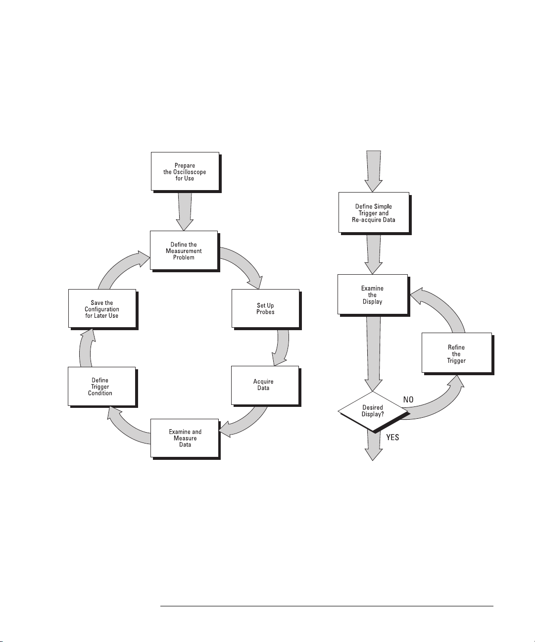
When you use the oscilloscopes to help test and troubleshoot your
systems, you may do the following:
• Prepare the oscilloscope by connecting it to power and setting up the
handle and screen intensity as desired.
• Define the measurement problem by understanding the parameters
of the system you wish to test, and the expected system behavior.
• Set up channel inputs by connecting the probes to the appropriate
signal and ground nodes in the circuit under test.
• Define the trigger to reference the waveform data at a specific event
of interest.
• Use the oscilloscope to acquire data, either in continuous or single-
shot fashion.
• Examine the data and make measurements on it using various
features.
• Save the measurement or configuration for later re-use or comparison
with other measurements.
Repeat the process as necessary until you verify correct operation or
find the source of the problem.
MegaZoom Technology Operates with Untriggered Data
With the MegaZoom technology built into the oscilloscope, you can
operate the oscilloscope with untriggered data. All you do is press
or
Single while in Auto trigger mode, then examine the data to set up a
trigger.
1-2
Run
Page 13
Getting Started
The oscilloscope’s high-speed display can be used to isolate infrequently
changing signals. You can then use the characteristics of these signals
to help refine the trigger specification. For more information on
triggering, data acquisition, data examination and measurement, and
configuration, see the later chapters.
Using the Oscilloscope, and Refining the Trigger Specification
1-3
Page 14

Setting up the Oscilloscope
To prepare your oscilloscope for use, you need to do the following tasks.
A ft er y ou ha v e c om pl e te d t he m , y ou w il l b e re ad y t o us e t he o sc il l os co pe .
In the following topics you will:
• inspect package contents
• inspect options and accessories
• learn how to clean the oscilloscope
• adjust the handle
• power-on the oscilloscope
• adjust the display intensity
• connect the oscilloscope probes
• connect the digital probes (with 54621D/22D/41D/42D)
• connect a printer
• connect a RS-232 cable
• verify basic oscilloscope operation
• get started using the oscilloscope interface
• learn how to use Quick Help
1-4
Page 15

Getting Started
To inspect package contents
To inspect package contents
❏ Inspect the shipping container for damage.
If your shipping container appears to be damaged, keep the shipping container
or cushioning material until you have inspected the contents of the shipment
for completeness and have checked the oscilloscope mechanically and
electrically.
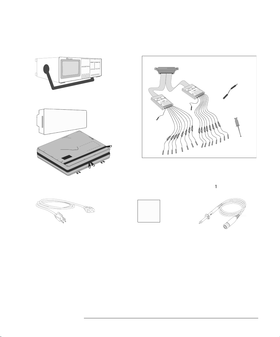
❏ Verify that you received the following items and any optional accessories in
the oscilloscope packaging (see figure following).
• 54620/40-Series Oscilloscope:
54621A, 21D, 22A, 22D, 24A, 41A, 41D, 42A, or 42D
• 10:1 passive probes with id:
(2) 10074C (150 MHz) for 54621A, 21D, 22A, or 22D
(4) 10074C (150 MHz) for 54624A
(2) 10073C (500 MHz) for 54641A, 41D, 42A, or 42D
• 54620-68701 digital probe kit for 54621D, 22D, 41D, or 42D
• Accessory pouch and front-panel cover standard for all except 54621A, 21D.
(54621A and 21D order N2726A)
• Power cord (see table 1-3)
• IntuiLink for 54600-series Oscilloscopes software and RS-232 cable (all
except for 54621A or 21D).
IntuiLink is a Windows application that makes it very easy for you to
download images, waveform data, or oscilloscope setups from the
oscilloscope to your pc using either Microsoft Word or Microsoft Excel. After
installation of IntuiLink, a tool bar in these Microsoft applications will make
connection and data transfer from the oscilloscope very simple.
For 54621A and 21D users, IntuiLink for 54600-series Oscilloscopes software
is available free on the web at:
www.agilent.com/find/5462xsw
RS-232 cable may be ordered separately, part number 34398A
1-5
Page 16

Getting Started
To inspect package contents
• Agilent IntuiLink Data Capture (all except for 54621A or 21D)
IntuiLink Data Capture is a standalone program for downloading waveform
data from the oscilloscopes to your PC via GPIB or RS-232 interface. It
provides the capability to transfer deep memory data out of the oscilloscope,
allowing up to 4MB (scope channels) and 8MB (logic channels). The
IntuiLink for 54600-Series limits the size of acquisition data available to a
maximum of 2,000 points regardless of actual number of acquisition points
on the screen. With the IntuiLink Data Capture, the amount of points
transferred will be the actual number of acquisition points currently
displayed or you may select the number of points to download. It provides
the following functionality:
• Download waveform data and display the data as a simple chart
• Save the data as binary or text files
• Copy the chart and a selected portion of the data to the clipboard. The
maximum data saved to the clipboard is 50,000 point
• Load saved waveform data back into the application
For 54621A and 21D users, IntuiLink Data Capture software is available free
on the web at:
www.agilent.com/find/5462xsw
RS-232 cable may be ordered separately, part number 34398A
If anything is missing, contact your nearest Agilent Sales Office. If the shipment
was d amag ed, contact the carrier, then c onta ct th e nearest Agilent Sales Office.
❏ Inspect the oscilloscope
• If there is mechanical damage or a defect, or if the oscilloscope does not
operate properly or does not pass the performance tests listed in the Service
Guide, notify your Agilent Sales Office.
• If the shipping container is damaged, or the cushioning materials show signs
of stress, notify the carrier and your Agilent Sales Office. Keep the shipping
materials for the carrier’s inspection. The Agilent Sales Office will arrange
for repair or replacement at Agilent’s option, without waiting for claim
settlement.
1-6
Page 17
Getting Started
To inspect package contents
54620/40-Series Oscilloscope
Accessories pouch and
front-panel cover**
Power cord
54620-68701 digital probe kit*
54620-61801 16-channel cable
IntuiLink for 54600-series
software, Data Capture
software and serial cable**
5959-9334 2” Ground
lead (qty 5)
5090-4356 Clip
(qty 20)
10073C or
10074C Probes
s
s1
* 54621D /22D/41D/42D only
** All except 54621A/21D
Package contents for 54620/40-Series Oscilloscopes
1-7
Page 18

Getting Started
To inspect options and accessories
To inspect options and accessories
❏ Verify that you received the options and accessories you ordered and that none
were damaged.
If anything is missing, contact your nearest Agilent Sales Office. If the shipment
wa s d am ag ed, or th e c us hion in g m at eria ls sh ow si gns o f s tr es s, noti fy th e carr ie r
and your Agilent Sales Office.
Some of the options and accessories available for the 54620/40-Series
Oscilloscopes are listed in tables 1-1 and 1-2. Contact your Agilent Sales Office
for a complete list of options and accessories.
Table 1-1
Options available
Option Description
003 Shielding Option for use in severe environments or with sensitive devices under
test–shields both ways (in and out):
RS-03 magnetic interface shielding added to CRT, and
RE-02 display shield added to CRT to reduce radiated interference.
1CM Rackmount kit (same as 1186A)
A6J ANSII Z540 compliant calibration with test data
W32 3-year, customer-return calibration service
W34 3-year, customer-return standard compliance calibration service
W50 Additional 2-year warranty (5 years total)
W52 5-year, customer-return calibration service
W54 5-year customer-return standard compliance calibration service
See table 1-3 for power cord options
1-8
Page 19

Getting Started
To inspect options and accessories
Table 1-2
Accessories available
Model Description
1146A Current probe, ac/dc
1183A Testmobile scope cart
1185A Carrying Case
1186A Rackmount Kit
10070C 1:1 Passive Probe with ID
10072A Fine-pitch probe kit
10075A 0.5 mm IC clip kit
10076A 100:1, 4 kV 250 MHz probe with ID
10085A 16:16 logic cable and terminator (for use with 54621D/22D/41D/42D)
10089A 16:2 x 8 logic input probe assembly ( shipped standard with 54621D/22D/41D/42D)
10100C 50
10833A GPIB cable, 1 m long
34398A RS-232 cable (standard except 54621A/21D)
E2613B 0.5 mm Wedge probe adapter, 3-signal, qty 2
E2614A 0.5 mm Wedge probe adapter, 8-signal, qty 1
E2615B 0.65 mm Wedge probe adapter, 3-signal, qty 2
E2616A 0.65 mm Wedge probe adapter, 8-signal, qty 1
E2643A 0.5 mm Wedge probe adapter, 16-signal, qty 1
E2644A 0.65 mm Wedge probe adapter, 16-signal, qty 1
N2726A Accessory pouch and front-panel cover (standard except on 54621A/21D)
N2727A Thermal printer and pouch
N2728A 10 rolls of thermal printer paper
N2757A GPIB Interface Module
N2772A 20 MHz differential probe
N2773A Differential probe power supply
N2774A 50 MHz current probe ac/dc
N2775A Power supply for N2774A
Ω Termination
1-9
Page 20
Getting Started
To inspect options and accessories
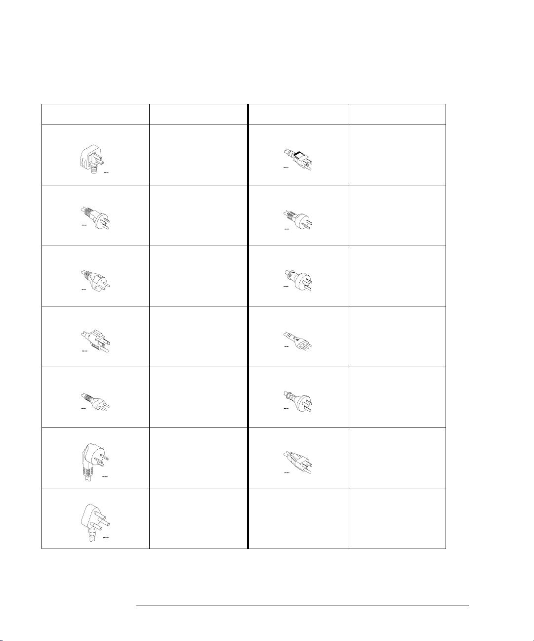
Table 1-3. Power Cords
Plug Type Cable Part Number Plug Type Cable Part Number
Opt 900 (U.K.) 8120-1703 Opt 918 (Japan) 8120-4754
Opt 901 (Australia) 8120-0696 Opt 919 (Israel) 8120-6799
Opt 902 (Europe) 8120-1692 Opt 920 (Argentina) 8120-6871
Opt 903 (U.S.A.) 8120-1521 Opt 921 (Chile) 8120-6979
Opt 906 (Switzerland) 8120-2296 Opt 922 (China) 8120-8377
Opt 912 (Denmark) 8120-2957 Opt 927 (Thailand) 8120-8871
Opt 917 (Africa) 8120-4600
1-10
Page 21

Getting Started
To clean the oscilloscope
To clean the oscilloscope
1 Disconnect power from the instrument.
CAUTION Do not use too much liquid in cleaning the oscilloscope. Water can enter the
front-panel keyboard, control knobs, or floppy disk damaging sensitive
electronic components.
2 Clean the oscilloscope with a soft cloth dampened with a mild soap and
water solution.
3 Make sure that the instrument is completely dry before reconnecting to
a power source.
1-11
Page 22
Getting Started
To adjust the handle
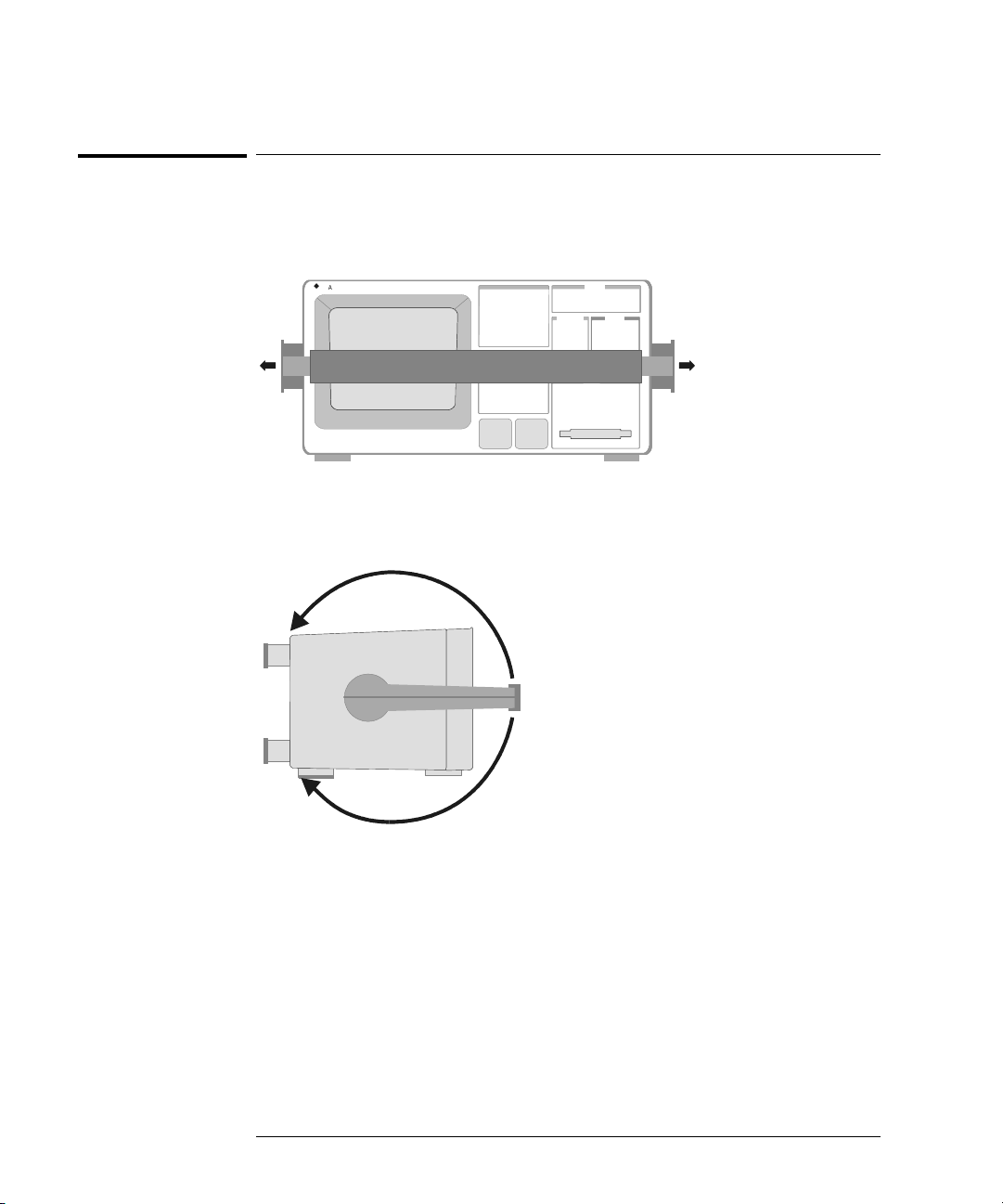
To adjust the handle
1 Grasp the handle pivot points on each side of the instrument and pull
the pivot out until it stops.
54622D
Agilent
s
MIXED SIGNAL OS CILLOSCOPE
CHANNEL
Select
Time/Div
150
5 ns1 s
INPUTS
2 Without releasing the pivots, swivel the handle to the desired position.
Then release the pivots. Continue pivoting the handle until it clicks into
a set position.
1-12
Page 23
Getting Started
To power-on the oscilloscope
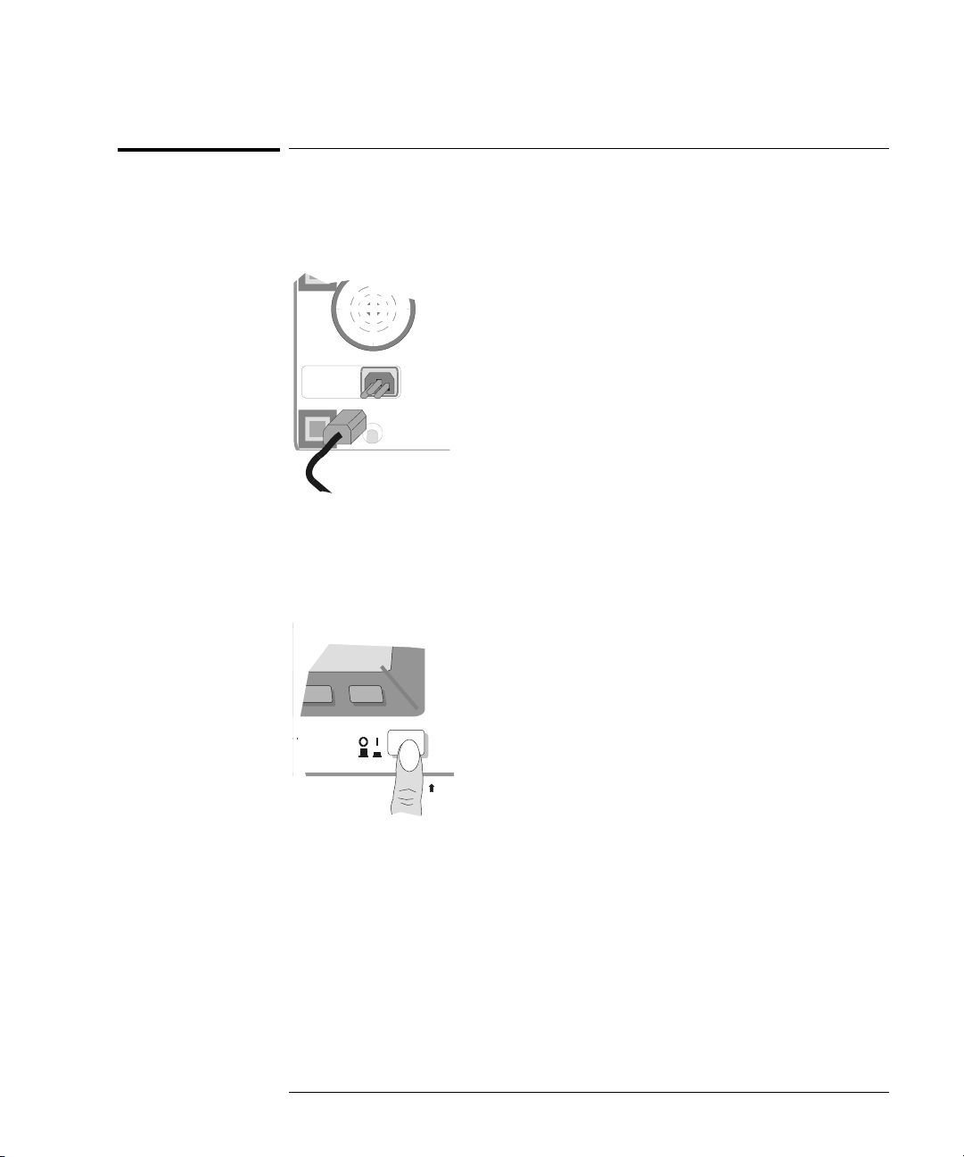
To power-on the oscilloscope
1 Connect the power cord to the rear of the oscilloscope, then to a
suitable ac voltage source.
The oscilloscope power supply automatically adjusts for input line voltages in
the range 100 to 240 VAC. Therefore, you do not need to adjust the input line
voltage setting. The line cord provided is matched to the country of origin.
Ensure that you have the correct line cord. See table 1-3
2 Press the power switch.
Trigger out
~5V
Some front panel key lights will come on and the oscilloscope will be operational
in about 5 seconds.
1-13
Page 24
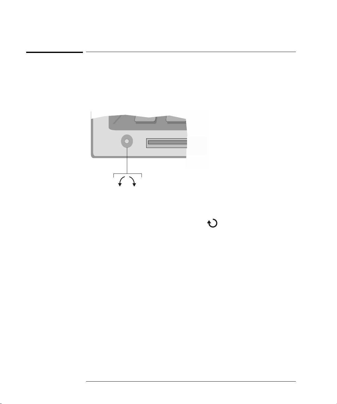
Figure 1-1
Getting Started
To adjust the waveform intensity
To adjust the waveform intensity
The Intensity control is at the lower left corner of the front panel.
• To decrease waveform intensity, rotate the Intensity control counterclockwise.
• To increase waveform intensity, rotate the Intensity control clockwise.
BrightDim
Intensity control
The grid or graticule intensity on the display can be adjusted by pressing the
Display key, then turn the Entry knob (labeled on the front panel) to adjust
the Grid control.
1-14
Page 25

Getting Started
To connect the oscilloscope analog probes
To connect the oscilloscope analog probes
The analog input impedance of these oscilloscopes is selectable either 50Ω
(54640-series only) or 1 M
used in making high frequency measurements. This impedance matching gives
you the most accurate measurements since reflections are minimized along the
signal path. The 1 M
measurements. The higher impedance minimizes the loading effect of the
oscilloscope on the circuit under test.
CAUTION Do not exceed 5 Vrms in 50Ω mode on the 54640-series models. Input
protection is enabled in 50
than 5 Vrm s i s d et ect ed . How ev er th e i np ut s co uld sti ll be dam ag ed , de pe nd ing
on the time constant of the signal.
CAUTION The 50Ω input protection mode on the 54640-series models only functions
when the oscilloscope is powered on.
Ω. The 50Ω mode matches 50Ω cables commonly
Ω mode is for use with probes and for general purpose
Ω mode and the 50Ω load will disconnect if greater
1 Connect the supplied 1.5-meter, 10:1 oscilloscope probe to an analog
channel BNC connector input on the oscilloscope.
Maximum input voltage for analog inputs:
CAT I 300 Vrms, 400 Vpk
CAT II 100 Vrms, 400 Vpk
with 10073C or 10074C 10:1 probe: CAT I 500 Vpk, CAT II 400 Vpk
2 Connect the retractable hook tip on the probe tip to the circuit point of
interest. Be sure to connect the probe ground lead to a ground point on
the circuit.
The probe ground lead is connected to the oscilloscope chassis and the ground
wire in the power cord. If you need to connect the ground lead to a point in the
circuit that cannot be grounded to power ground, consider using a differential
probe.
1-15
Page 26

Perfectly compensated
Over compensated
Getting Started
To compensate your analog probe
To compensate your analog probe
You should compensate you analog probes to match their characteristics to the
oscilloscope. A poorly compensated probe can introduce measurement errors.
To compensate a probe, follow these steps:
1 Connect the probe from channel 1 to the Probe Comp signal on the lower-
right corner of the front panel.
2Press
3 Use a nonmetallic tool to adjust the trimmer capacitor on the probe for
Autoscale.
the flattest pulse possible.
Under compensated
comp.cdr
1-16
Page 27
Getting Started
To use the digital probes (mixed-signal oscilloscope only)
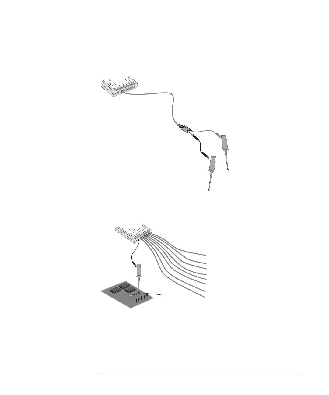
To use the digital probes (mixed-signal oscilloscope
only)
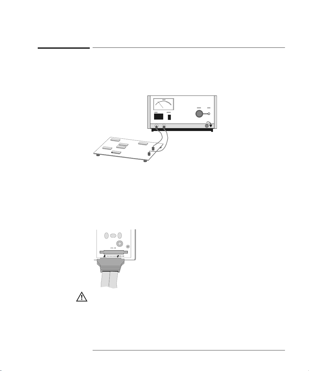
1 If you feel it’s necessary, turn off the power supply to the circuit under
test.
Off
Turning off power to the circuit under test would only prevent damage that
might occur if you accidentally short two lines together while connecting
probes. You can leave the oscilloscope powered on because no voltage appears
at the probes.
2 Connect the digital probe cable to D15 - D0 connector on the front panel
of the mixed-signal oscilloscope. The digital probe cable is indexed so
you can connect it only one way. You do not need to power-off the
oscilloscope.
Use only the Agilent part number 54620-68701 digital probe kit supplied with
the mixed-signal oscilloscope. Additional probe kits may be ordered by
specifying Agilent part number 10089A.
1-17
Page 28
Getting Started
To use the digital probes (mixed-signal oscilloscope only)
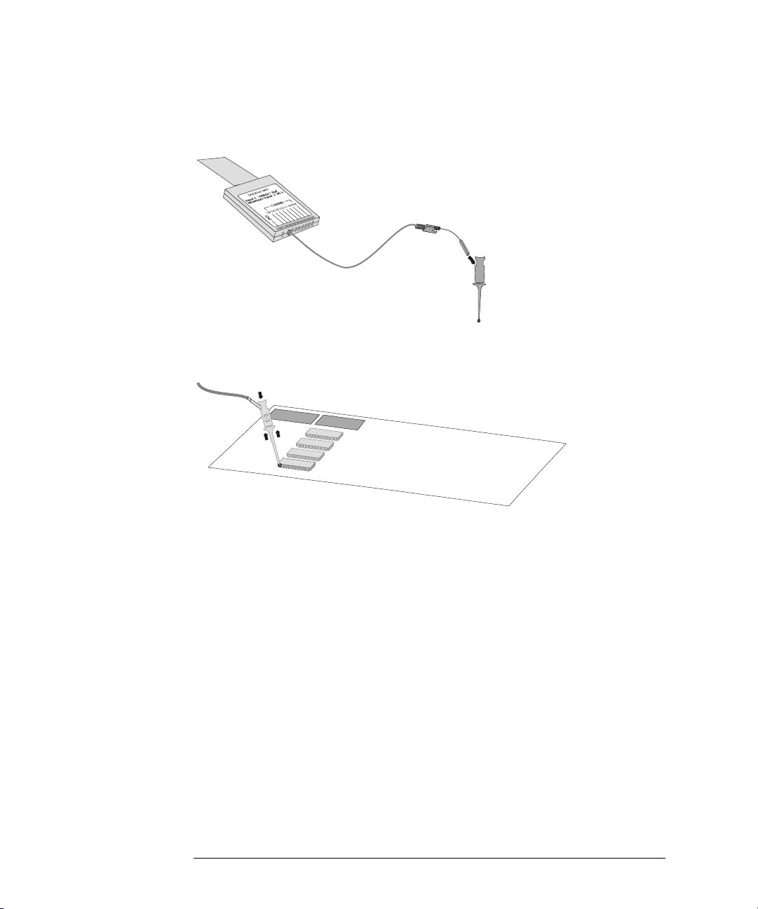
3 Connect a clip to one of the probe leads. Be sure to connect the ground
lead. (Other probe leads are omitted from the figure for clarity.)
Clip
4 Connect the clip to a node in the circuit you want to test.
1-18
Page 29
Getting Started
To use the digital probes (mixed-signal oscilloscope only)
5 For high-speed signals, connect a ground lead to the probe lead, connect
a clip to the ground lead, and attach the clip to ground in the circuit
under test.
Signal Lead
Ground Lead
Clip
6 Connect the ground lead on each set of channels, using a probe clip.
The ground lead improves signal fidelity to the instrument, ensuring
accurate measurements.
Channel
Pod Ground
Circuit
Ground
1-19
Page 30
Getting Started
To use the digital probes (mixed-signal oscilloscope only)
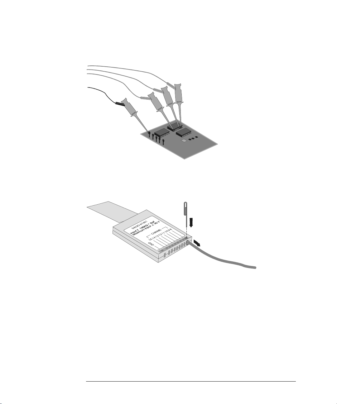
7 Repeat steps 3 through 6 until you have connected all points of interest.
Signals
Ground
8 If you need to remove a probe lead from the cable, insert a paper clip
or other small pointed object into the side of the cable assembly, and
push to release the latch while pulling out the probe lead.
Replacement parts are available. See the Replaceable Parts chapter in the
Service Guide for details.
1-20
Page 31

Getting Started
To connect a printer
To connect a printer
The oscilloscope connects to a parallel printer through the Parallel output
connector on the rear of the oscilloscope. You will need a parallel printer cable
to connect to the printer.
1 Attach the 25-pin small “D” connector to the Parallel output connector
on the rear of the oscilloscope. Tighten the thumbscrews on the cable
connector to secure the cable.
2 Attach the larger 36-pin “D” connector to the printer.
3 Set up the printer configuration on the oscilloscope.
a Press the Utility key, then press the Print Confg softkey.
b Press the Print to: softkey and set the interface to Parallel.
c Press the Format softkey and select your printer format from the list.
For more information on printer configuration, refer to the “Utilities” chapter.
To connect an RS-232 cable
The oscilloscope can be connected to a controller or a pc through the RS-232
connector on the rear of the oscilloscope. An RS-232 cable is shipped with each
oscilloscope except 54621A/21D and may be purchased for the 54621A/21D
oscilloscopes.
1 Attach the 9-pin “D” connector on the RS-232 cable to the RS-232
connector on the rear of the oscilloscope. Tighten the thumbscrews on
the cable connector to secure the cable
2 Attach the other end of the cable to your controller or pc.
3 Set up the RS-232 configuration on the oscilloscope.
a Press the Utility key, then press the I/O softkey.
b Press the Controller softkey and select RS-232.
c Press the Baud softkey and set the baud rate to match your controller or pc.
d Press the XON DTR softkey and set the handshake to match your controller
or pc.
For more information on RS-232 configuration, refer to the “Utilities” chapter.
1-21
Page 32

Getting Started
To verify basic oscilloscope operation
To verify basic oscilloscope operation
1 Connect an oscilloscope probe to channel 1.
2 Attach the probe to the Probe Comp output on the lower-right side of
the front panel of the oscilloscope.
Use a probe retractable hook tip so you do not need to hold the probe.
3Press the Save/Recall key on the front panel, then press the Default Setup
softkey under the display.
The oscilloscope is now configured to its default settings.
4Press the Autoscale key on the front panel.
You should then see a square wave with peak-to-peak amplitude of about 5
divisions and a period of about 4 divisions as shown below. If you do not see
the waveform, ensure your power source is adequate, the oscilloscope is
properly powered-on, and the probe is connected securely to the front-panel
channel input BNC and to the Probe Comp calibration output.
Verifying Basic Oscilloscope Operation
1-22
Page 33

Getting started using the oscilloscope interface
When the oscilloscope is first turned on, a startup screen is displayed as
shown below.
This menu is only accessible when the oscilloscope first starts up.
1-23
Page 34

Getting Started
To verify basic oscilloscope operation
•Press the Getting Started softkey to view the symbols used in the
oscilloscope softkey menus.
Use the Entry knob labeled to adjust the parameter.
Press the softkey to display a pop up with a list of choices. Repeatedly
press the softkey until your choice is selected.
Use the Entry knob labeled or press the softkey to adjust the
parameter.
✓ Option is selected and operational.
Feature is on. Press the softkey again to turn the feature off.
Feature is off. Press the softkey again to turn the feature on.
Links you to another menu.
Press the softkey to view the menu.
1-24
Press the softkey to return to the previous menu.
Page 35

Using Quick Help
The oscilloscope has a Quick Help system that provides user help for
each front-panel key and softkey on the oscilloscope. To view Quick Help
information:
1Press
2 Release the key after reading the message. Releasing the key returns
and hold down the key for which you would like to view help.
the oscilloscope to the previous state.
Selecting a language for Quick Help when the oscilloscope starts up
When the oscilloscope first powers up, you can press the Language softkey to
select a language for viewing Quick Help. Successively press the Language
softkey until the desired language in the list is selected.
You can also select a language later from the Utility Language menu.
1-25
Page 36

Getting Started
Selecting a language for Quick Help after you have been operating the oscilloscope
Selecting a language for Quick Help after you have been
operating the oscilloscope
1Press the Utility key, then press the Language softkey to display the
Language menu.
2Press the
selected.
Language softkey until the desired language in the list is
When updates occur, an updated language file can be downloaded from:
www.agilent.com/find/5462xsw
www.agilent.com/find/5464xsw
or call an Agilent center and request a language disk for your instrument
1-26
for the 54620-series or
for the 54640-series,
Page 37

Getting Started
Loading an updated language file from floppy disk
Loading an updated language file from floppy disk
When updates occur, an updated language file can be downloaded from:
www.agilent.com/find/5462xsw
www.agilent.com/find/5464xsw
or call an Agilent center and request a language disk for your instrument.
1 Insert the floppy disk containing the language file into the floppy disk
drive on the oscilloscope.
2Press the
Utility key, then press the Language softkey to display the
Language menu.
3Press the
Load Languages softkey to load the updated language file into
the oscilloscope.
4Press the
For more information about loading languages, refer to the “Utilities” chapter.
Language softkey and select the language to be viewed.
for the 54620-series or
for the 54640-series,
1-27
Page 38

1-28
Page 39

2
Front-Panel Overview
Page 40

Front-Panel Overview
Before you make measurements using the Agilent 54620-series and
54640-series Oscilloscopes, you must first set up the instrument using
front-panel controls. Then, make the measurement and read the display
results.
These oscilloscopes operate much like an analog scope, but they can do
much more. Spending a few minutes to learn some of these capabilities
will take you a long way toward more productive troubleshooting. The
“MegaZoom Concepts and Oscilloscope Operation” chapter has more
detail on the things to consider while operating your oscilloscope.
The keys on the front panel bring up softkey menus on the display that
allow access to oscilloscope features. Many softkeys use the Entry
knob to select values.
Throughout this book, the front-panel keys and softkeys are denoted by
a change in the text type. For example, the
panel and the
above its corresponding key. Other softkey graphic conventions used
on the oscilloscope and throughout this guide are shown in the “Getting
started using the oscilloscope interface” topic in chapter 1.
Normal softkey appears at the bottom of the display directly
Cursors key is on the front
2-2
Page 41

Front-Panel Overview
Important Oscilloscope Considerations
Important Oscilloscope Considerations
Using Single versus Run/Stop
The oscilloscopes have a Single key and a Run/Stop key. When you press Run
(key is illuminated in green), the trigger processing and screen update rate are
optimized over the memory depth. Single acquisitions always use the maximum
memory available—at least twice as much memory as acquisitions captured in
Run mode—and the scope stores at least twice as many samples. At slow sweep
speeds, the oscilloscope operates at a higher sample rate when Single is used
to capture an acquisition, as opposed to running, due to the increased memory
available.
Using Auto trigger mode versus Normal trigger mode
Normal trigger mode requires a trigger to be detected before an acquisition can
complete. In many cases, a triggered display in not needed to check signal levels
or activity. For these applications, use Auto trigger mode. If you only want to
acquire specific events as specified by the trigger settings, use Normal trigger
mode. For more detailed discussion of Auto trigger mode and Normal trigger
mode, refer to Chapter 3, “Triggering the Oscilloscope.”
Viewing signal detail with acquire mode
Remember how you had to constantly adjust the brightness on old analog scopes
to see a desired level of detail in a signal, or to see the signal at all? With the
Agilent 54620/40-series oscilloscopes, this is not necessary. The Intensity knob
ope ra te s muc h l ik e the br ig ht nes s k no b o n you r c om pute r s cr ee n, s o y ou sh oul d
set it to a level that makes for comfortable viewing, given the room lighting, and
leave it there. Then you can control the detail by selecting an Acquire mode:
Normal, Peak Detect, Average, or Realtime as described in the following
paragraphs.
Normal acquire mode Normal mode is the acquisition mode that you will
probably use for acquiring samples most of the time. It compresses up to 2
million acquisition points per channel for the 54620-series and up to 4 million
acquisition points per channel for the 54640-series into a 1,000-pixel column
display record.
The 54620-series 200 MSa/s sampling speed specification means that samples
are taken every 5 ns. The 54640-series 2 GSa/s sampling speed specification
means that samples are taken every 500 ps. At the faster sweep speeds, the
running display is built from many individual triggers. If you press the Stop key,
and pan and zoom through the waveform by using the Horizontal and Vertical
knobs, only the last trigger’s acquisition will be displayed.
2-3
Page 42

Front-Panel Overview
Important Oscilloscope Considerations
Whether the oscilloscope is stopped or running, you see more detail as you zoom
in, and less as you zoom out. Zoom means you expand the waveform using
either the main or delayed sweep window. Panning the waveform means you
use the Horizontal Delay time knob( )to move it horizontally. To keep from
losing detail as you zoom out, switch to the Peak Detect acquisition mode.
Peak Detect acquire mode Peak Detect for the 54620-series and for the
54640-series functions as follows:
• 54620-series In Peak Detect acquisition mode, any noise, peak, or signal
wider than 5 ns will be displayed, regardless of sweep speed. In Normal
acq uisition mo de, at sweep speed s fa ster than 1 ms/div, yo u wou ld se e a 5-ns
peak, so peak detect has no effect at sweep speeds faster than 1 ms/div.
• 54640-series In Peak Detect acquisition mode, any noise, peak, or signal
wider than 1 ns will be displayed, regardless of sweep speed. In Normal
acquisition mode, at sweep speeds faster than 500
1-ns peak, so peak detect has no effect at sweep speeds faster than 500
Using Peak Detect and infinite persistence together is a powerful way to find
spurious signals and glitches.
Average acquire mode Averaging is a way to pull a repetitive signal out of
noise. Averaging works better than either a brightness control or a bandwidth
limit because the bandwidth is not reduced except when smoothing (number
of averages=1) is selected.
The simplest averaging is smoothing (number of averages = 1). For example,
on the 54620-series, the sample rate at a Time/Div setting of 2 ms/div allows the
extra 5-ns samples to be smoothed together, smoothing the data into one
sample, which is then displayed. Averaging (number of averages > 1) needs a
stable trigger, because in this mode multiple acquisitions are averaged together.
See the “MegaZoom Concepts and Oscilloscope Operation” chapter for more
information about smoothing.
µs/div, you would see a
µs/div.
2-4
Page 43

Front-Panel Overview
Important Oscilloscope Considerations
Realtime acquire mode In Realtime mode, the oscilloscope produces the
waveform display from samples collected during one trigger event. The sample
rate for the 54620-series is 200 MSa/s for single channel or 100 MSa/s with
channel pairs 1 and 2, 3 and 4, or pod 1 and pod 2 running. The sample rate for
the 54640-series is 2 GSa/s for single channel or 1 GSa/s with channel pairs 1
and 2, or pod 1 and pod 2 running.
When less than 1000 samples can be collected in the time spanned by the screen,
a sophisticated reconstruction filter is used to fill in and enhance the waveform
display.
To accurately reproduce a sampled waveform, the sample rate should be at least
four times the highest frequency component of the waveform. If not, it is
possible for the reconstructed waveform to be distorted or aliased. Aliasing is
most commonly seen as jitter on fast edges.
When Realtime mode is off, the oscilloscope produces the waveform display
from samples collected from multiple triggers, when on fast sweep speeds. In
this case, the reconstruction filter is not used. When the trigger is stable, this
produces the highest fidelity waveform.
Realtime mode is only necessary at sweep speeds of 200 ns/div and faster for
the 54620-series and 2
ranges <1000 samples can be collected on each trigger. While the effective
bandwidth of the channel is reduced slightly, Realtime mode produces a
complete waveform for each trigger.
Realtime can be turned on when any other acquisition mode is turned on. Use
Realtime to capture infrequent triggers, unstable triggers, or complex changing
waveforms, such as eye diagrams.
µs/div and faster for the 54640-series, since on these
Using Vectors (Display menu)
One of the most fundamental choices you must make about your display is
whether to draw vectors (connect the dots) between the samples, or simply let
the samples fill in the waveform. To some degree, this is a matter of personal
preference, but it also depends on the waveform.
• You will probably operate the oscilloscope most often with vectors on.
Complex analog signals like video and modulated signals show analog-like
intensity information with vectors on.
• Turn vectors off when the maximum display rate is required, or when highly
complex or multi-valued waveforms are displayed. Turning vectors off may
aid the display of mulitvalued waveforms such as eye diagrams.
2-5
Page 44

Front-Panel Overview
Important Oscilloscope Considerations
Delayed Sweep
Delayed sweep is a simultaneous display of the waveform at two different sweep
speeds. Because of the deep memory in the MegaZoom technology, it is possible
to capture the main display at 1 ms/div, and redisplay the same trigger in the
delayed display at any desired faster time base.
There is no limit imposed on the zoom ratio between the main and delayed
displays. There is, however, a useful limit when the samples are spaced so far
apart that they are of little value. See the “MegaZoom Concepts and
Oscilloscope Operation” chapter for more information about delayed sweep and
time reference.
Post Acquisition Processing
In addition to changing display parameters after the acquisition, you can do all
of the measurements and math functions after the acquisition. Measurements
and math functions will be recalculated as you pan and zoom and turn channels
on and o ff. As you zoom in and out on a signal using the horizontal sweep spe ed
knob and vertical volts/division knob, you affect the resolution of the display.
Because measurements and math functions are performed on displayed data,
you affect the resolution of functions and measurements.
2-6
Page 45

Figure 2-1
Front-Panel Overview
54620/40-series Oscilloscope Front Panels
54620/40-series Oscilloscope Front Panels
Intensity
control
Display
Softkeys
Floppy
disk
Measure
keys
Entry
knob
Autoscale
key
Power
switch
Horizontal
controls
Vertical
inputs/
controls
Waveform
keys
File
keys
Run
controls
Trigger
controls
Utility
key
Probe
comp
output
External
Trigger
input
54621A, 54622A, 54641A, and 54642A 2-Channel Oscilloscopes Front Panel
2-7
Page 46

Figure 2-2
Front-Panel Overview
54620/40-series Oscilloscope Front Panels
Intensity
control
Display
Softkeys
Floppy
disk
Measure
keys
Entry
knob
Autoscale
key
Power
switch
Horizontal
controls
Vertical
inputs/
controls
Waveform
keys
File
keys
Run
controls
Trigger
controls
Utility
key
Probe
comp
output
54624A 4-Channel Oscilloscope Front Panel
2-8
Page 47

Figure 2-3
Front-Panel Overview
54620/40-series Oscilloscope Front Panels
Intensity
control
Display
Softkeys
Floppy
disk
Measure
keys
Entry
knob
Autoscale
key
Power
switch
Horizontal
controls
Analog Channel
inputs/ controls
Waveform
keys
File
keys
Run
controls
Trigger
controls
Utility
key
Probe
Comp
output
Digital Channel
inputs/ controls
54621D, 54622D, 54641D, and 54642D Mixed-Signal Oscilloscopes Front Panel
2-9
Page 48

Front-Panel Operation
This chapter provides a brief overview of interpreting information on the
display and an introduction to operating the front-panel controls.
Detailed oscilloscope operating instructions are provided in later
chapters.
54621D, 54622D. 54641D, and 54642D digital channels
Because all of the oscilloscopes in the 54620/40-series have analog channels, the
analog channel topics in this chapter apply to all instruments. Whenever a topic
discusses the digital channels, that information applies only to the 54621D, 54622D,
54641D, or 54642D Mixed-Signal Oscilloscopes.
2-10
Page 49

Front-Panel Overview
Interpreting the display
Interpreting the display
The oscilloscope display contains channel acquisitions, setup information,
measurement results, and softkeys for setting up parameters.
Analog
channels
sensitivity
Status line
Analog
channels and
ground levels
Digital
channels
Measurement
line
Softkeys
Digital
channel
activity
Interpreting the display
Trigger point,
time reference
Delay
time
Sweep
speed
Trigger
mode
Trigger
type
Trigger
source
Trigger level
or digital
threshold
Cursor
markers
defining
measurement
Status line The top line of the display contains vertical, horizontal, and trigger
setup information.
Display area The display area contains the waveform acquisitions, channel
identifiers, and analog trigger and ground level indicators.
Measurement line This line normally contains automatic measurement and
cursor results, but can also display advanced trigger setup data and menu
information.
Softkeys The softkeys allow you to set up additional parameters for
front-panel keys.
2-11
Page 50

Front-Panel Overview
To use analog channels to view a signal
To use analog channels to view a signal
• To configure the oscilloscope quickly, press the Autoscale key to display
the connect signal.
• T o un do th e ef fe ct s of Au to s ca l e, pr es s th e
pressing any other key.
This is useful if you have unintentionally pressed the Autoscale key or do not
like the settings Autoscale has selected and want to return to your previous
settings.
• To set the instrument to the factory-default configuration, press the
Save/Recall key, then press the Default Setup softkey.
Example Connect the oscilloscope probes for channels 1 and 2 to the Probe Comp output
on the front panel of the instrument. Be sure to connect the probe ground l ead s
to the lug above the Probe Comp output. Set the instrument to the factory
default configuration by pressing the Save/Recall key, then the Default Setup
softkey. Then press the Autoscale key. You should see a display similar to the
following.
Undo Autoscale softkey before
Autoscale with analog channels
2-12
Page 51

Front-Panel Overview
To use digital channels to view a signal
To use digital channels to view a signal
• To configure the oscilloscope quickly, press the Autoscale key to display
the connected signals.
• T o un do th e ef fe ct s of Au to s ca l e, pr es s th e
pressing any other key.
This is useful if you have unintentionally pressed the Autoscale key or do not
like the settings Autoscale has selected and want to return to your previous
settings.
• To set the instrument to the factory-default configuration, press the
Save/Recall key, then press the Default Setup softkey.
Example Install probe clips on channels 0 and 1 on the digital probe cable. Connect the
pr obes for di gital channe ls 0 and 1 to the P robe Comp o utp ut on t he fr ont pa nel
of the instrument. Be sure to connect the ground lead. Set the instrument to
the factory default configuration by pressing the Save/Recall key, then the
Default Setup softkey. Then press the Autoscale key. You should see a display
similar to the following.
Undo Autoscale softkey before
Autoscale with digital channels (54621D, 54622D, 54641D, and 54642D)
2-13
Page 52

Front-Panel Overview
To display signals automatically using Autoscale
To display signals automatically using Autoscale
• To configure the instrument quickly, press the Autoscale key.
Autoscale displays all connected signals that have activity.
To undo the effects of Autoscale, press the Undo Autoscale softkey before
pressing any other key.
How Autoscale Works
Autoscale automatically configures the oscilloscope to best display the input
signal by analyzing any waveforms connected to the external trigger and
channel inputs. Autoscale finds, turns on, and scales any channel with a
repetitive waveform with a frequency of at leas t 50 Hz, a duty cycle greater than
0.5%, and an amplitude of at least 10 mV peak-to-peak. Any channels that do
not meet these requirements are turned off.
The trigger source is selected by looking for the first valid waveform starting
with external trigger, then continuing with the highest number analog channel
down to the lowest number analog channel, and finally (if applicable) the
highest number digital channel.
During Autoscale, the delay is set to 0.0 seconds, the sweep speed setting is a
function of the input signal (about 2 periods of the triggered signal on the
screen), and the triggering mode is set to edge. Vectors remain in the state they
were before the Autoscale.
Undo Autoscale
Press the Undo Autoscale softkey to return the oscilloscope to the settings that
existed before you pressed the Autoscale key.
This is useful if you have unintentionally pressed the Autoscale key or do not
like the settings Autoscale has selected and want to return to your previous
settings.
The Channels softkey selection determines which channels will be displayed on
subsequent Autoscales.
All Channels - The next time you press Autoscale, all channels that meet the
requirements of Autoscale will be displayed.
Only Displayed Channels - The next time you press Autoscale, only the
channels that are turned on will be displayed. This is useful if you only want
to view specific active channels after pressing Autoscale.
2-14
Page 53

Front-Panel Overview
To apply the default factory configuration
To apply the default factory configuration
• To set the instrument to the factory-default configuration, press the
Save/Recall key, then press the Default Setup softkey.
The default configuration returns the oscilloscope to its default settings. This
places the oscilloscope in a known operating condition. The major default
settings are:
Horizontal main mode, 100 us/div scale, 0 s delay, center time reference
Vertical (Analog) Channel 1 on, 5 V/div scale, dc coupling, 0 V position, 1 M
impedance, probe factor to 1.0 if an AutoProbe probe is not connected to the
channel
Trigger Edge trigger, Auto sweep mode, 0 V level, channel 1 source, dc
coupling, rising edge slope, 60 ns holdoff time
Display Vectors on, 20% grid intensity, infinite persistence off
Other Acquire mode normal, Run/Stop to Run, cursors and measurements off
Labels all custom labels in the Label Library are erased
Ω
2-15
Page 54

Front-Panel Overview
To adjust analog channel vertical scaling and position
To adjust analog channel vertical scaling and position
This exercise guides you through the vertical keys, knobs, and status line.
1 Center the signal on the display using the position knob.
The position knob ( ) moves the signal vertically; the signal is calibrated.
Notice that as you turn the pos ition knob, a voltage value is displayed for a short
time, indicating how far the reference ( )is located from the center of the
screen. Also notice that the ground reference symbol at the left edge of the
display moves with the position knob.
Measurement Hints
If the channel is DC coupled, you can quickly measure the DC component of the
signal by simply noting its distance from the ground symbol.
If the channel is AC coupled, the DC component of the signal is removed, allowing
you to use greater sensitivity to display the AC component of the signal.
2 Change the vertical setup and notice that each change affects the status
line differently. You can quickly determine the vertical setup from the
status line in the display.
• Change the vertical sensitivity with the large volts/division knob in the
Vertical (Analog) section of the front panel and notice that it causes the
status line to change.
•Press the 1 key.
If channel 1 was not turned on, a softkey menu appears on the display, and
the channel turns on (the 1 key will be illuminated).
If channel 1 was already turned on, but another menu was being displayed,
the softkeys will now display the channel 1 menu.
When Vernier is turned off, the volts/div knob can change the channel sensitivity
in a 1-2-5 step sequence. When Vernier is selected, you can change the channel
sensitivity in smaller increments with the volts/division knob. The channel
sensitivity remains fully calibrated when Vernier is on. The sensitivity value is
displayed in the status line at the top of the display.
• To turn the channel off, press the channel 1 key until the key is not
illuminated.
2-16
Page 55

Front-Panel Overview
To set the vertical expand reference for the analog signal
To set the vertical expand reference for the analog signal
When changing the volts/division for analog channels, you can have the signal
expand (or compress) about the signal ground point or about the center
graticule on the display. This works well with two signals displayed, because
you can position and see them both on the screen while you change the
amplitude.
• To expand the signal about the center graticule of the display, press the Utility
key, press the Options softkey, then press the Expand softkey and select
Expand About Center.
With Expand About Center selected, when you turn the volts/division, the
waveform with expand or contract about the center graticule of the display.
• To expand the signal about the position of the channel’s ground, press the
Utility key, press the Options softkey. Then press the Expand softkey and
select Expand About Ground.
With Expand About Ground selected, when you turn the volts/division knob,
the ground level of the waveform remains at the same point on the display,
while the non-ground portions of the waveform expand or contract.
To set analog channel probe attenuation factor
If you have an AutoProbe self-sensing probe (such as the 10073C or 10074C)
connected to the analog channel, the oscilloscope will automatically configure
your probe to the correct attenuation factor.
If you do not have an AutoProbe probe connected, you can press the channel
key, then press the Probe submenu softkey, then turn the Entry knob to
set the attenuation factor for the connected probe. The attenuation factor can
be set from 0.1:1 to 1000:1 in a 1-2-5 sequence.
Th e pro be cor rect ion factor must be set prope rly f or m easurements t o be m ade
correctly.
2-17
Page 56

Front-Panel Overview
To display and rearrange the digital channels
To display and rearrange the digital channels
1Press the D15 Thru D8 key or D7 Thru D0 key to turn the display of the digital
channels on or off.
The digital channels are displayed when these keys are illuminated.
2 Turn the Digital Channel Select knob to select a single digital channel.
The selected channel number is highlighted on the left side of the display.
3 Turn the Digital position knob ( ) to reposition the selected channel
on the display.
If two or more channels are displayed at the same position, a pop up will appear
showing the overlaid channels. Continue turning the Channel Select knob until
the desired channel within the pop up is selected.
2-18
Page 57

Front-Panel Overview
To operate the time base controls
To operate the time base controls
The following exercise guides you through the time base keys, knobs, and status
line.
• Turn the Horizontal sweep speed (time/division) knob and notice the
change it makes to the status line.
The sweep speed knob changes the sweep speed from 5 ns/div to 50 s/div for
the 54620-series and 1 ns/div to 50 s/div for the 54640-series in a 1-2-5 step
sequence, and the value of the sweep speed is displayed in the status line at the
top of the display.
•Press the Main/Delayed, then press the Vernier softkey.
The Vernier softkey allows you to change the sweep speed in smaller increments
with the time/div knob. These smaller increments are calibrated, which results
in accurate measurements, even with the vernier turned on.
• Turn the delay time knob ( ) and notice that its value is displayed in
the status line.
The delay knob moves the main sweep horizontally, and it pauses at 0.00 s,
mimicking a mechanical detent. At the top of the graticule is a solid triangle
(
▼) s ym b o l an d a n op e n t r i a ng l e ( ∇) s y mb o l . Th e ▼ symbol indicates the trigger
point and it moves with the Delay time knob. The
reference point and is also where the zoom-in/zoom-out is referenced. If the
Tim e Ref softkey is set to Left, the
of the display. If the Time Ref softkey is set to Center, the
center of the display. If the Time Ref softkey is set to Right, the
graticule in from the right side of the display. The delay number tells you how
far the time reference point
All events displayed left of the trigger point
occurred, and these events are called pre-trigger information. You will find this
fe at ur e v ery u se fu l b ecau se yo u can no w s ee the ev en ts that le d u p to th e t ri gge r
point. Everything to the right of the trigger point
information. The amount of delay range (pre-trigger and post-trigger
information) available depends on the sweep speed selected.
∇ is located one graticule in from the left side
∇ is located from the trigger point ▼.
∇ symbol indicates the time
∇ is located at the
∇ is located one
▼ happened before the trigger
▼ is called post-trigger
2-19
Page 58

Front-Panel Overview
To start and stop an acquisition
To start and stop an acquisition
• When the Run/Stop key is illuminated in green, the oscilloscope is in
continuous running mode.
You are viewing multiple acquisitions of the same signal similar to the way an
analog oscilloscope displays waveforms.
• When the Run/Stop key is illuminated in red, the oscilloscope is stopped.
“Stop” is displayed in the trigger mode position in status line at the top of the
display. You may now pan and zoom the stored waveform by turning the
Horizontal and Vertical knobs.
The stopped display may contain several triggers worth of information, but only
the last trigger acquisition is available for pan and zoom. To ensure the display
does not change, use the Single key to be sure you have acquired only one
trigger.
•The Run/Stop key may flash between a user requesting a Stop and the
completion of the current acquisition.
To make a single acquisition
The Single run control key lets you view single-shot events without subsequent
waveform data overwriting the display. Use Single when you want maximum
memory depth for pan and zoom and you want the maximum sample rate.
1 First set trigger Mode/Coupling Mode softkey to Normal.
This keeps the oscilloscope from autotriggering immediately.
2 If you are using the analog channels to capture the event, turn the
Trigger Level knob to the trigger threshold where you think the trigger
should work.
3 To begin a single acquisition, press the
When you press Single, the display is cleared, the trigger circuitry is armed, the
Single key is illuminated, and the oscilloscope will wait until a trigger condition
occurs before it displays a waveform.
When the oscilloscope triggers, the single acquisition is displayed and the
oscilloscope is stopped (Run/Stop key is illuminated in red). Press Single again
to acquire another waveform.
2-20
Single key.
Page 59

Front-Panel Overview
To use delayed sweep
To use delayed sweep
Delayed sweep is an expanded version of main sweep. When Delayed mode is
selected, the display divides in half and the delayed sweep icon displays in
the middle of the line at the top of the display. The top half displays the main
sweep and the bottom half displays the delayed sweep.
The following steps show you how to use delayed sweep. Notice that the steps
are very similar to operating the delayed sweep in analog oscilloscopes.
1 Connect a signal to the oscilloscope and obtain a stable display.
2Press
3Press the
Main/Delayed.
Delayed softkey.
To change the sweep speed for the delayed sweep window, turn the sweep speed
knob. As you turn the knob, the sweep speed is highlighted in the status line
above the waveform display area.
Th e area of the main disp lay that is e xpanded is in tensified and marked on ea ch
end with a vertical marker. These markers show what portion of the main sweep
is expanded in the lower half. The Horizontal knobs control the size and position
of the delayed sweep. The delay value is momentarily displayed in the
upper-right portion of the display when the delay time ( ) knob is turned.
Delayed sweep is a magnified portion of the main sweep. You can use delayed
sweep to locate and horizontally expand part of the main sweep for a more
detailed (higher-resolution) analysis of signals.
To change th e sweep speed f or the main sweep wind ow, pre ss th e Main softkey,
then turn the sweep speed knob.
2-21
Page 60

Front-Panel Overview
To make cursor measurements
To make cursor measurements
Yo u c an use th e c ur sors to ma ke cust om vo lt age o r t im e m easu re me nts on sc op e
signals, and timing measurements on digital channels.
1 Connect a signal to the oscilloscope and obtain a stable display.
2Press the
Mode Set the cursors results to measure voltage and time (Normal), or display
the binary or hexadecimal logic value of the displayed waveforms.
Source selects a channel or math function for the cursor measurements.
X Y Select either the X cursors or the Y cursors for adjustment with the Entry
knob.
X1 and X2 adjust horizontally and normally measure time.
Y1 and Y2 adjust vertically and normally measure voltage.
X1 X2 and Y1 Y2 move the cursors together when turning the Entry knob.
For more information about using cursors for measurements, refer to the
“Making Measurements” chapter.
Cursors key. View the cursor functions in the softkey menu:
2-22
Page 61

Front-Panel Overview
To make automatic measurements
To make automatic measurements
You can use automatic measurements on any channel source or any running
math function. Cursors are turned on to focus on the most recently selected
measurement (right-most on the measurement line above the softkeys on the
display).
1Press the Quick Meas key to display the automatic measurement menu.
2Press the
on which the quick measurements will be made.
Only channels or math functions that are displayed are available for
measurements. If you choose an invalid source channel for a measurement, the
measurement will default to the nearest in the list that makes the source valid.
If a portion of the waveform required for a measurement is not displayed or does
not display enough resolution to make the measurement, the result will be
displayed with a message such as greater than a value, less than a value, not
enough edges, not enough amplitude, incomplete, or waveform is clipped to
indicate that the measurement may not be reliable.
3Press the Clear Meas softkey to stop making measurements and to erase
the measurement results from the measurement line above the
softkeys.
When Quick Meas is pressed again, the default measurements on an analog
channel will be will be Frequency and Peak-Peak.
4 Choose what measurement you want on that source by pressing the
Select softkey, then turn the Entry knob to select the desired
measurement from the popup list.
5Press the Measure softkey to make the selected measurement.
6To turn off
illuminated.
For detailed information about making automatic measurements, refer to the
“Making Measurements” chapter.
Source softkey to select the channel or running math function
Quick Meas, press the Quick Meas key again until it is not
2-23
Page 62

Front-Panel Overview
To modify the display grid
To modify the display grid
1Press the Display key.
2 Turn the Entry knob to change the intensity of the displayed grid. The
intensity level is shown in the
Grid softkey and is adjustable from 0 to
100%.
Each major division in the grid (also know as graticule) corresponds to the
sweep speed time shown in the status line on the top of the display.
• To change waveform intensity, turn the INTENSITY knob on the
lower-left corner of the front panel.
To print the display
You can print the complete display, including the status line and softkeys, to a
parallel printer or to the floppy disk by pressing the Quick Print key. You can
stop printing by pressing the Cancel Print softkey.
To set up your printer, press the Utility key, then press the Print Confg softkey.
For more information on printing and floppy disk operation, refer to the
“Utilities” chapter.
2-24
Page 63

3
Triggering the Oscilloscope
Page 64

Triggering the Oscilloscope
The Agilent 54620/40-series Oscilloscopes provide a full set of features
to help automate your measurement tasks, including MegaZoom
technology to help you capture and examine the stored waveforms of
interest, even untriggered waveforms. With these oscilloscopes you can:
• modify the way the oscilloscope acquires data.
• set up simple or complex trigger conditions, as needed, to capture
only the sequence of events you want to examine.
The oscilloscopes all have common triggering functionality:
• Trigger modes
Auto
Normal
Auto Level (54620-series only)
• Coupling (including high frequency and noise rejection)
•Holdoff
• Trigger Level
• External Trigger input
• Trigger types
Edge (slope)
Pulse width (glitch)
Pattern
CAN
Duration
2
I
C
Sequence
SPI
TV
USB
• Trigger Out connector
3-2
Page 65

Selecting Trigger Modes and Conditions
The trigger mode affects the way in which the oscilloscope searches for
the trigger. The figure below shows the conceptual representation of
acquisition memory. Think of the trigger event as dividing acquisition
memory into a pre-trigger and post-trigger buffer. The position of the
trigger event in acquisition memory is defined by the time reference
point and the delay setting.
Trigger Event
Pre-Trigger Buffer
Acquisition Memory
Acquisition Memory
Post-Trigger Buffer
To select the Mode and Coupling menu
•Press the Mode/Coupling key in the Trigger section of the front panel.
3-3
Page 66

Triggering the Oscilloscope
To select a trigger mode: Normal, Auto, Auto Level
To select a trigger mode: Normal, Auto, Auto Level
1Press the Mode/Coupling key.
2Press the
• Normal mode displays a waveform when the trigger conditions are met,
otherwise the oscilloscope does not trigger and the display is not updated.
• Auto mode is the same as Normal mode, except it forces the oscilloscope to
trigger if the trigger conditions are not met.
• Auto Level mode (54620-series only) works only when edge triggering on
analog channels or external trigger. The oscilloscope first tries to Normal
trigger. If no trigger is found, it searches for a signal at least 10% of full scale
on the trigger source and sets the trigger level to the 50% amplitude point.
If there is still no signal present, the oscilloscope auto triggers. This mode
is useful when moving a probe from point to point on a circuit board.
Auto Level and Auto modes
Use th e a uto tr ig ge r mo de s f or sig na ls othe r t ha n l ow- re pe ti tive -r at e sign al s a nd
for unknown signal levels. To display a dc signal, you must use one of these two
auto trigger modes since there are no edges on which to trigger.
Auto Level mode (54620-series only) is the same as Auto mode with an
automatic trigger level adjustment. The oscilloscope looks at the level on the
signals, and if the trigger level is out-of-range with respect to the signal, the
scope adjusts the trigger level back to the middle of the signal.
When you select Run, the oscilloscope operates by first filling the pre-trigger
buffer. It starts searching for a trigger after the pre-trigger buffer is filled, and
continues to flow data through this buffer while it searches for the trigger. While
searching for the trigger, the oscilloscope overflows the pre-trigger buffer; the
first data put into the buffer is the first pushed out (FIFO). When a trigger is
found, the pre-trigger buffer will contain the events that occurred just before
the trigger. If no trigger is found, the oscilloscope generates a trigger and
displays the data as though a trigger had occurred.
When you select Single, the oscilloscope will fill pre-trigger buffer memory, and
continue flowing data through the pre-trigger buffer until the auto trigger
overrides the searching and forces a trigger. At the end of the trace, the scope
will stop and display the results.
Mode softkey, then select Normal, Auto, or Auto Level mode.
3-4
Page 67

Triggering the Oscilloscope
To select a trigger mode: Normal, Auto, Auto Level
Normal mode
Use Normal trigger mode for low repetitive-rate signals or when Auto trigger is
not required. In this mode, the oscilloscope has the same behavior whether the
acquisition was initiated by pressing Run/Stop or Single.
In Normal mode the oscilloscope must fill the pre-trigger buffer with data before
it will begin searching for a trigger event. The trigger mode indicator on the
status line flashes to indicate the oscilloscope is filling the pre-trigger buffer.
While searching for the trigger, the oscilloscope overflows the pre-trigger buffer;
the first data put into the buffer is the first pushed out (FIFO).
When the trigger event is found, the oscilloscope will fill the post-trigger buffer
and display the acquisition memory. If the acquisition was initiated by Run/Stop,
the process repeats. The waveform data will be scrolled onto the display as it
is being acquired.
In either Auto or Normal mode, the trigger may be missed completely under
certain conditions. This is because the oscilloscope will not recognize a trigger
event until the pre-trigger buffer is full. Suppose you set the Time/Div knob to
a slow sweep speed, such as 500 ms/div. If the trigger condition occurs before
the oscilloscope has filled the pre-trigger buffer, the trigger will not be found.
If you use Normal mode and wait for the trigger condition indicator to flash
before causing the action in the circuit, the oscilloscope will always find the
trigger condition correctly.
Some measurements you want to make will require you to take some action in
the circuit under test to cause the trigger event. Usually, these are single-shot
acquisitions, where you will use the Single key.
3-5
Page 68

Triggering the Oscilloscope
To select trigger Coupling
To select trigger Coupling
1Press the Mode/Coupling key.
2Press the
• DC coupling allows dc and ac signals into the trigger path.
• AC coupling places a high-pass filter (3.5 Hz for 54620-series analog channels,
10 Hz for 54640-series analog channels, and 3.5 Hz for all External trigger
inputs) in the trigger path removing any DC offset voltage from the trigger
waveform. Use AC coupling to get a stable edge trigger when your waveform
has a large DC offset.
• LF (low frequency) Reject coupling places a 50-kHz high-pass filter in series
with the trigger waveform. Low frequency reject removes any unwanted low
frequency components from a trigger waveform, such as power line
frequencies, that can interfere with proper triggering. Use this coupling to
get a stable edge trigger when your waveform has low frequency noise.
• TV coupling is normally grayed-out, but is automatically selected when TV
trigger is enabled in the Trigger More menu.
Coupling softkey, then select DC, AC, or LF Reject coupling.
To select Noise Reject and HF Reject
1Press the Mode/Coupling key.
2Press the
softkey to select high frequency reject.
• Noise Rej adds additional hysteresis to the trigger circuitry. When noise reject
is on, the trigger circuitry is less sensitive to noise but may require a greater
amplitude waveform to trigger the oscilloscope.
• HF Reject adds a 50 kHz low-pass filter in the trigger path to remove high
frequency components from the trigger waveform. You can use HF Reject to
remove high-frequency noise, such as AM or FM broadcast stations or from
fast system clocks, from the trigger path.
3-6
Noise Rej softkey to select noise reject or press the HF Reject
Page 69

Triggering the Oscilloscope
To set holdoff
To set holdoff
1Press the Mode/Coupling key.
2 Turn the Entry knob to increase or decrease the trigger holdoff
time shown in the
Holdoff sets the amount of time that the oscilloscope waits before re-arming the
trigger circuitry. Use Holdoff to stabilize the display of complex waveforms.
To get a stable trigger on the pulse burst shown below, set the holdoff time to
be >200 ns but <600 ns.
Holdoff softkey.
+ROGRII
QV QV
By setting the Holdoff, you can synchronize triggers. The oscilloscope will
trigger on one edge of the waveform, and ignore further edges until the holdoff
time expires. The oscilloscope will then re-arm the trigger circuit to search for
the next edge trigger. This allows the oscilloscope to trigger on a repeating
pattern in a waveform.
6FRSHWULJJHUVKHUH
3-7
Page 70

Triggering the Oscilloscope
To set holdoff
Holdoff Operating Hints
Holdoff keeps a trigger from occurring until after a certain amount of time has passed
since the last trigger. This feature is valuable when a waveform crosses the trigger
level multiple times during one period of the waveform.
Without holdoff, the scope could trigger on each of the crossings, producing a
confusing waveform. With holdoff set correctly, the scope always triggers on the
same crossing. The correct holdoff setting is typically slightly less than one period.
Set the holdoff to this time to generate a unique trigger point. This action works even
though many waveform periods pass between triggers, because the holdoff circuit
operates on the input signal continuously.
Changing the time base settings does not affect the holdoff number. In contrast, the
holdoff in analog oscilloscopes is a function of the time base setting, making it
necessary to re-adjust the holdoff each time you change the time base setting.
With Agilent’s MegaZoom technology, you can press Stop, then pan and zoom
through the data to find where it repeats. Measure this time using the cursors, then
set holdoff to this number.
3-8
Page 71

Triggering the Oscilloscope
External Trigger Input
External Trigger Input
External Trigger can be used as a source in several of the trigger types. On
4-channel and mixed-signal oscilloscopes, the external trigger BNC input is on
the rear panel and is labeled Ext Trig. On 2-channel oscilloscopes, the external
trigger BNC input is on the front panel and is labeled Ext Trigger.
Maximum input voltage for the external trigger input:
CAT I 300 Vrms, 400 Vpk
CAT II 100 Vrms, 400 Vpk
with 10073C or 10074C 10:1 probe: CAT I 500 Vpk, CAT II 400 Vpk
CAUTION Do not exceed 5 Vrms in 50Ω mode on the 54640-series models. Input
protection is enabled in 50
than 5 Vrms is detected. However the input could still be damaged, depending
on the time constant of the signal.
Ω mode and the 50Ω load will disconnect if greater
CAUTION The 50Ω input protection mode on the 54640-series models only functions
when the oscilloscope is powered on.
External Trigger Probe Settings
You can set probe attenuation, units, and input impedance for the external
trigger input.
1Press the Mode/Coupling key in the Trigger section of the front panel.
3-9
Page 72

Triggering the Oscilloscope
External Trigger Input
2Press the External softkey to display the external trigger probe menu.
Attenuation
factor
Measurement
units
Input impedance
(54640-series)
Return to
previous menu
Probe Attenuation Turn the Entry knob to set the attenuation factor
displayed in the Probe softkey for the connected probe. The attenuation factor
can be set from 0.1:1 to 1000:1 in a 1-2-5 sequence.
For 2-channel oscilloscopes that have the Ext Trigger connector on the front
panel, when you connect an AutoProbe self-sensing probe, the oscilloscope will
automatically configure your probe to the correct attenuation factor.
The probe correction factor must be set properly for measurements to be made
correctly.
Probe Units Press the Units softkey to select the proper measurement unit
for the connected probe. Select Volts for a voltage probe and select Amps for a
current probe. Measurement results, channel sensitivity, and trigger level will
reflect the measurement units you have selected.
Input Impedance The 54620-series oscilloscope external trigger input
impedance is always 1 M
Ω. The 54640-series oscilloscope external trigger input
impedance can be set to either 1M Ohm or 50 Ohm by pressing the Imped sof tkey.
• 50 Ohm mode matches 50-ohm cables commonly used in making high
frequency measurements. This impedance matching gives you the most
accurate measurements since reflections are minimized along the signal
path.
• 1M Ohm mode is for u se wi th pr obes and f or gen eral -purpose mea sur ement s.
The higher impedance minimizes the loading effect of the oscilloscope on
the circuit under test.
For 2-channel oscilloscopes that have the Ext Trigger connector on the front
panel, when you connect an AutoProbe self-sensing probe, the oscilloscope will
automatically configure your probe to the correct impedance.
3-10
Page 73

Trigger Types
The oscilloscope allows you to synchronize the display to the actions of
the circuit under test by defining a trigger condition. You can use any
input channel or the Ext Trigger BNC for the source for most trigger
types.
MegaZoom Technology Simplifies Triggering
With the built-in MegaZoom technology, you can simply Autoscale the waveforms,
then stop the scope to capture a waveform. You can then pan and zoom through the
data using the Horizontal and Vertical knobs to find a stable trigger point. Autoscale
often produces a triggered display.
These trigger types are available and are presented in the following order in this
chapter:
• Edge trigger
• Pulse Width (glitch) trigger
• Pattern trigger
• CAN (Controller Area Network) trigger
• Duration trigger
2
C (Inter-IC bus) trigger
•I
• Sequence trigger
• SPI (Serial Protocol Interface) trigger
• TV trigger
• USB (Universal Serial Bus) trigger
Changes to the trigger specification are applied when you make them. If the
oscilloscope is stopped when you change a trigger specification, the scope will
use the new specification when you press Run/Stop or Single. If the oscilloscope
is running when you change a triggering specification, it uses the new trigger
definition when it starts the next acquisition. You select the trigger type by
pressing the key associated with the desired trigger type.
3-11
Page 74

Triggering the Oscilloscope
To use Edge triggering
To use Edge triggering
The Edge trigger type identifies a trigger by looking for a specified slope and
voltage level on a waveform. You can define the trigger source and rising or
falling edge in this menu. The trigger type, source, and level is displayed in the
upper-right corner of the display.
1Press the Edge key in the Trigger section of the front panel to display
the Edge trigger menu.
Slope
Trigger
source
Trigger level
or threshold
Slope
Analog channel
source
Digital channel
source
External or Line
source
2 Press the slope softkey ( ) and select either rising edge or falling
edge. This determines whether the trigger will occur on the rising edge
or the falling edge of the input signal.
Slope Selects rising edge ( ) or falling edge ( ) for the selected trigger
source. The selected slope is displayed in the upper-right corner of the display.
3 Select 1, 2, Ext, or Line as the trigger source.
The trigger source can also be set to channel 3 and 4 on the 4-channel
oscilloscope, or can be set to digital channels D15 through D0 on the
mixed-signal oscilloscope. You can choose a channel that is turned off as the
source for the edge trigger. The selected trigger source is displayed in the
upper-right corner of the display next to the slope symbol:
1 through 4 = analog channels
D15 through D0 = digital channels
E = External trigger
L = Line trigger
3-12
Page 75

Triggering the Oscilloscope
To use Edge triggering
Analog source Press the analog channel source softkey to select an analog
source. Adjust the trigger level for the selected analog channel by turning the
Trigger Level knob. The position of the trigger level for the analog channel is
indicated by the trigger level icon (if the analog channel is on) at the far left
T
side of the display when DC coupling is selected. The value of the analog
channel trigger level is displayed in the upper-right corner of the display.
Digital source (mixed-signal oscilloscope) Press the digital source
softkey or turn the Entry knob to select a digital channel (D15-D0) as the trigger
source. Select Threshold in the D7 Thru D0 or D15 Thru D8 menu to set the
threshold level (TTL, CMOS, ECL, or user defined) for the selected digital
channel group. The threshold value is displayed in the upper-right corner of the
display.
External/Line source Ext (external trigger) and Line (triggers off the power
line frequency) trigger share the same softkey on the display. Toggle the softkey
to select the source you want.
The external trigger input is on the front panel of the 2-channel oscilloscope
and on the rear-panel of 4-channel and mixed-signal oscilloscope. You can
connect the trigger output of other instruments to this external trigger input,
or use an oscilloscope probe, such as the 10073C or 10074C.
Adjust the external trigger level for the selected analog channel by turning the
Trigger Level knob. The trigger level for Line is not adjustable.
3-13
Page 76

Triggering the Oscilloscope
To use Pulse Width triggering
To use Pulse Width triggering
Pulse Width (glitch) triggering sets the oscilloscope to trigger on a positive pulse
or a negative pulse of a specified width. If you want to trigger on a specific
timeout value, use Duration trigger in the trigger More menu.
1Press the Pulse Width key in the Trigger section of the front panel to
display the Pulse Width trigger menu.
Trigger level
or threshold
Source
2Press the
Trigger
source
Pulse
polarity
Polarity
Qualifier Qualifier time set
Source softkey (or rotate the Entry knob on mixed-signal
oscilloscopes) to select a channel source for the trigger.
The channel you select is shown in the upper-right corner of the display next
to the polarity symbol.
The source can be any analog or digital channel available on your oscilloscope.
External trigger may also be specified as a source when using the 2-channel and
4-channel oscilloscopes.
Adjust the trigger level for the selected analog channel source by turning the
Trigger Level knob. The position of the trigger level for the analog channel is
indicated by the trigger level icon (if the analog channel is on) at the far left
side of the display when DC coupling is selected. Set the threshold for the
selected digital channel group by pressing the D7 Thru D0 or D15 Thru D8 key
then press the Threshold softkey. The value of the trigger level or digital
threshold is displayed in the upper-right corner of the display.
T
3-14
Page 77

Triggering the Oscilloscope
To use Pulse Width triggering
3 Press the pulse polarity softkey to select positive ( )or negative ( )
polarity for the pulse width you want to capture.
The selected pulse polarity is displayed in the upper-right corner of the display.
A positive pulse is higher than the current trigger level or threshold and a
negative pulse is lower than the current trigger level or threshold.
When triggering on a positive pulse, the trigger will occur on the high to low
transition of the pulse if the qualifying condition is true. When triggering on a
negative pulse, the trigger will occur on the low to high transition of the pulse
if the qualifying condition is true.
4 Press the qualifier softkey (< > ><) to select the time qualifier.
The Qualifier softkey can set the oscilloscope to trigger on a pulse width that is:
• less than a time value (<).
For example, for a positive pulse, if you set t<10 ns:
10 ns
• greater than a time value (>).
For example, for a positive pulse, if you set t>10 ns:
10 ns
Trigger
10 ns10 ns
• within a range of time values (><).
For example, for a positive pulse, if you set t>10 ns and t<15 ns:
10 ns
15 ns
12 ns
Trigger
Trigger
3-15
Page 78

Triggering the Oscilloscope
To use Pulse Width triggering
5 Select the qualifier time set softkey (< or >), then rotate the Entry knob
to set the pulse width qualifier time.
The qualifiers can be set as follows:
54620-series
• 5 ns to 10 for > or < qualifier
• 10 ns to 10 s for >< qualifier, with minimum difference of 5 ns between upper and lower
settings
54640-series
• 2 ns to 10 s for > or < qualifier when source is analog channel or external trigger
• 5 ns to 10 s for > or < qualifier when source is digital channel
• 10 ns to 10 s for >< qualifier , with minimum difference of 5 ns between upper and lower
settings.
< qualifier time set softkey
• When the less than (<) qualifier is selected, the Entry knob sets the
oscilloscope to trigger on a pulse width less than the time value displayed
on the softkey.
• When the time range (><) qualifier is selected, the Entry knob sets the
upper time range value.
> qualifier time set softkey
• When the greater than (>) qualifier is selected, the Entry knob sets the
oscilloscope to trigger on a pulse width greater than the time value
displayed on the softkey.
• When the time range (><) qualifier is selected, the Entry knob sets the
lower time range value.
3-16
Page 79

Triggering the Oscilloscope
To use Pattern triggering
To use Pattern triggering
The Pattern trigger identifies a trigger condition by looking for a specified
pattern. This pattern is a logical AND combination of the channels. Each
channel can have a value of high (H), low (L), don’t care (X). A rising or falling
edge can be specified for one channel included in the pattern.
1Press the Pattern key in the Trigger section of the front panel to display
the Pattern trigger menu.
Pattern
trigger
Selected
channel
Trigger level
or threshold
Channel
select
Logic Low
Logic High Don’t care Rising or
falling edge
2 For each analog or digital channel you want to include in the desired
pattern, press the
This is the channel source for the H, L, X, or edge condition. As you press the
Channel softkey (or rotate the Entry knob on mixed-signal oscilloscopes), the
channel you select is highlighted in the Pattern = line directly above the
softkeys and in the upper-right corner of the display next to "Pat". External
trigger may also be specified as a channel in the pattern when using the
2-channel and 4-channel oscilloscopes.
Adjust the trigger level for the selected analog channel by turning the Trigger
Level knob. The position of the trigger level for the analog channel is indicated
by the trigger level icon at the far left side of the display when DC coupling
is selected Set the threshold for the selected digital channel group by pressing
the D7 Thru D0 or D15 Thru D8 key then press the Threshold softkey. The value
of the trigger level or digital threshold is displayed in the upper-right corner of
the display.
Channel softkey to select the channel.
T
3-17
Page 80

Triggering the Oscilloscope
To use Pattern triggering
3 For each channel you select, press one of the condition softkeys to set
the condition for that channel in the pattern.
• H sets the pattern to high on the selected channel. A high is a voltage level
that is greater than the channel's trigger level or threshold level.
• L sets the pattern to low on the selected channel. A low is a voltage level that
is less than the channel's trigger level or threshold level.
• X sets the pattern to don't care on the selected channel. Any channel set to
don't care is ignored and is not used as part of the pattern. If all channels in
the pattern are set to don't care, the oscilloscope will not trigger.
• The rising edge ( ) or falling edge ( ) falling edge softkey sets the pattern
to an edge on the selected channel. Only one rising or falling edge can be
specified in the pattern. When an edge is specified, the oscilloscope will
trigger at the edge specified if the pattern set for the other channels is true.
If no edge is specified, the oscilloscope will trigger on the last edge that makes
the pattern true.
Specifying an Edge in a Pattern
You are allowed to specify only one rising or falling edge term in the pattern. If
you define an edge term, then select a different channel in the pattern and define
another edge term, the previous edge definition is changed to a don’t care.
3-18
Page 81

Triggering the Oscilloscope
To use CAN triggering
To use CAN triggering
Controller Area Network (CAN) trigger will trigger on CAN version 2.0A and
2 . 0B s i g na l s . Se t u p co n s i st s o f c o nn ec t in g t h e o sc i ll o s c op e t o a C A N s ig n a l . P r e s s
the Settings so ft ke y t o spe ci fy baud ra te , s ign al so ur ce, an d s ig nal t yp e t o tri gg er
on.
The CAN trigger will trigger on the Start of Frame (SOF) bit of a Data frame,
Remote Transfer Request (RTR) frame, or an Overload frame. A CAN message
frame in CAN_L signal type is shown below:
Bus
Idle
ControlArbitration
Field Field
Data
Field
CRC
Field
ACK
Field
EOF
Inter-
mission
SOF edge
1Press the More key in the Trigger section of the front panel, rotate the
Entry knob until
Settings softkey to display CAN trigger menu.
Signal
baud rate
CAN is displayed in the Trigg er softkey, then press the
Trigger on:
condition
Signal type
and polarity
Currently selected
signal source
CAN trigger
Signal
source
Trigger level
or threshold
Return to
previous menu
3-19
Page 82

Triggering the Oscilloscope
To use CAN triggering
2Press the Baud softkey to set the CAN signal baud rate.
The CAN baud rate can be set to:
10 kb/s 50 kb/s 125 kb/s 800 kb/s
20 kb/s 83.3 kb/s 250 kb/s 1 Mb/s
33.3 kb/s 100 kb/s 500 kb/s
The default baud rate is 1 Mb/s
3Press the Trigger: softkey to select the trigger condition.
The SOF (S ta r t o f Fr a me ) is t he o nl y tr i gg e r c o nd i ti o n a v ai l ab l e. T he C AN tr ig g er
will trigger on the Start of Frame bit of a Data frame, Remote Transfer Request
(RTR) frame, or an Overload frame.
4Press the Signal softkey to set the type and polarity of the CAN signal.
This also automatically sets the channel label for the source channel. The
channel shown in the Source softkey can be connected as follows:
Dominant high signal:
• CAN_H - the actual CAN_H differential bus signal.
Dominant low signals:
• CAN_L - the actual CAN_L differential bus signal.
• Rx - the Receive signal from the CAN bus transceiver.
• Tx - the Transmit signal to the CAN bus transceiver.
• Differential - the CAN differential bus signals connected to an analog
source channel using a differential probe.
5Press the Source softkey to select the channel connected to the CAN
signal line.
If the Signal softkey is set to Differential, connect an analog source channel to
the CAN differential bus signal using a differential probe.
As you press the Source softkey (or rotate the Entry knob on mixed-signal
oscilloscopes), the CAN label f or the sour ce channel is automat ically set and t he
channel you select is shown in the upper-right corner of the display next to
"CAN".
Adjust the trigger level for the selected analog channel by turning the Trigger
Level knob. Select Threshold in the D7 Thru D0 or D15 Thru D8 menu to set the
level for digital channels. The value of the trigger level or digital threshold is
displayed in the upper-right corner of the display.
3-20
Page 83

Triggering the Oscilloscope
To use Duration triggering
To use Duration triggering
Duration trigger lets you define a pattern, then trigger on a specified time
duration of this logical AND combination of the channels.
1Press the More key in the Trigger section of the front panel, rotate the
Entry knob until
Settings softkey to display the Duration trigger menu.
the
Duration is displayed in the Trigger softkey, then press
Trigger level
or threshold
Return to
previous menu
Channel
select
Logic level
Qualifier
Duration
trigger
Qualifier time set
Selected
channel
2 For each analog or digital channel you want to include in the desired
pattern, press the
This is the channel source for the H, L, or X condition. As you press the Channel
softkey (or rotate the Entry knob on mixed-signal oscilloscopes), the channel
you select is highlighted in the Pattern = line directly above the softkeys and
in the upper- rig ht corner of the display next to "Dur". External trigger may also
be specified as a channel in the pattern when using the 2-channel and 4-channel
oscilloscopes.
Adjust the trigger level for the selected analog channel by turning the Trigger
Level knob. The position of the trigger level for the analog channel is indicated
by the trigger level icon at the far left side of the display when DC coupling
is selected Set the threshold for the selected digital channel group by pressing
the D7 Thru D0 or D15 Thru D8 key then press the Threshold softkey. The value
of the trigger level or digital threshold is displayed in the upper-right corner of
the display.
Channel softkey to select the channel.
T
3-21
Page 84

Triggering the Oscilloscope
To use Duration triggering
3 For each channel you select, press the logic level softkey to set the
condition for that channel in the pattern.
• H sets the pattern to high on the selected channel. A high is a voltage level
that is greater than the channel's trigger level or threshold level.
• L sets the pattern to low on the selected channel. A low is a voltage level that
is less than the channel's trigger level or threshold level.
• X sets the pattern to don't care on the selected channel. Any channel set to
don't care is ignored and is not used as part of the pattern. If all channels in
the pattern are set to don't care, the oscilloscope will not trigger.
4Press the Qualifier softkey to set the time duration qualifier for the
pattern.
The time qualifier can set the oscilloscope to trigger on a channel pattern whose
time duration is:
• less than a time value (<)
• greater than a time value (>)
• greater than a time value, but with timeout (Timeout ). A trigger will be forced
at the timeout value, rather than occurring when the pattern is exited.
• within a range of time values (><)
• outside a range of time values (<>)
The time values for the selected qualifier are set using the qualifier time set
softkeys (< and >) and the Entry knob.
3-22
Page 85

Triggering the Oscilloscope
To use Duration triggering
5 Select a qualifier time set softkey (< or >), then rotate the Entry knob to
set the duration qualifier time.
< qualifier time set softkey
• When the less than (<) qualifier is selected, the Entry knob sets the
oscilloscope to trigger on a pattern duration less than the time value
displayed on the softkey.
• When the within time range (><) qu alifier is sel ecte d, the Entr y knob sets
the upper time range value.
• When the out of time range (<>) qualifier is selected, the Entry knob sets
the lower time range value.
> qualifier time set softkey
• When the greater than (>) qualifier is selected, the Entry knob sets the
oscilloscope to trigger on a pattern duration greater than the time value
displayed on the softkey.
• When the within time range (><) qu alifier is sel ecte d, the Entr y knob sets
the lower time range value.
• When the out of time range (<>) qualifier is selected, the Entry knob sets
the upper time range value.
• When Timeout qualifier is selected, the Entry knob sets the timeout value.
When the duration trigger occurs
The timer starts on the last edge that makes the pattern (logical AND) true. The
trigger will occur on the first edge that makes the pattern false if the time qualifier
criteria of the pattern has been met, except in Timeout mode. In Timeout, the trigger
occurs when the timeout value is reached while the pattern is true.
3-23
Page 86

Triggering the Oscilloscope
To use I2C triggering
To use I2C triggering
An I2C (Inter-IC bus) trigger setup consists of connecting the oscilloscope to
the serial data (SDA) line and the serial clock (SCL) line, then triggering on a
stop/start condition, a restart, a missing acknowledge, an EEPROM data read,
or on a read/write frame with a specific device address and data value.
1Press the More key in the Trigger section of the front panel, rotate the
Entry knob until
Settings softkey to display the I
I2C is displayed in the Tri gger softkey, then press the
2
C trigger menu.
SCL Clock
channel
SDA Data
channel
Trigger on:
condition
Currently selected Clock
I2C trigger
Address
or Data channel
Data
value
Trigger level
or threshold
Return to
previous menu
2 Connect an oscilloscope channel to the SCL (serial clock) line in the
circuit under test, then set the
As you press the SCL softkey (or rotate the Entry knob on mixed-signal
oscilloscopes), the SCL label f or the sour ce channel is automat ically set and t he
channel you select is shown in the upper-right corner of the display next to
2
"I
C".
Adjust the trigger level for the selected analog channel by turning the Trigger
Level knob. For the mixed-signal oscilloscope, select Threshold in the D7 Thru
D0 or D15 Thru D8 menu to set the level for digital channels assigned to the clock
and data lines. The value of the trigger level or digital threshold is displayed in
the upper-right corner of the display.
SCL clock channel softkey to that channel.
3-24
Page 87

Triggering the Oscilloscope
To use I2C triggering
3 Connect an oscilloscope channel to the SDA (serial data) line in the
circuit under test, then set the
As you press the SDA softkey (or rotate the Entry knob on mixed-signal
oscilloscopes), the SDA l ab el f or the source c hannel is automat ically set and t he
channel you select is shown in the upper-right corner of the display next to
2
"I
C".
Adjust the trigger level for the selected analog channel by turning the Trigger
Level knob. For the mixed-signal oscilloscope, select Threshold in the D7 Thru
D0 or D15 Thru D8 menu to set the level for digital channels assigned to the clock
and data lines. The value of the trigger level or digital threshold is displayed in
the upper-right corner of the display.
Data needs to be stable during the whole high clock cycle or it will be interpreted
as a start or stop condition (data transitioning while the clock is high).
SDA data channel softkey to that channel.
4Press the Tri gg er: softkey to select one of the following I2C trigger
conditions:
Start Condition: the oscilloscope triggers when SDA data transitions from high
to low while the SCL clock is high. For triggering purposes (including frame
triggers), a restart is treated as a start condition.
Stop Condition: the oscilloscope triggers when data (SDA) transitions from low
to high while the clock (SCL) is high.
SDA
SCL
Start
Condition
Address
Ack Data
AckR/W
Stop
Condition
Missing Acknowledge: the oscilloscope triggers when SDA data is high during
any Ack SCL clock bit.
Restart: the oscilloscope triggers when another start condition occurs before a
stop condition.
3-25
Page 88

Triggering the Oscilloscope
To use I2C triggering
EEPROM Data Read: the trigger looks for EEPROM control byte value 1010xxx
on the SDA line, followed by a Read bit and an Ack bit. It then looks for the data
value and qualifier set by the Data softkey and the Data is softkey. When this
event occurs, the scope will trigger on the clock edge for the Ack bit after the
data byte. This data byte does not need to occur directly after the control byte.
Read
SDA
SCL
Start or
Control byte R/W
Restart Condition
Ack
Data Ack
Trigger point
Frame (Start: Addr7: Read: Ack: Data) or
Frame (Start: Addr7: Write: Ack: Data): the oscilloscope triggers on a read or write
frame in 7-bit addressing mode on the 17th clock edge if all bits in the pattern
match. For triggering purposes, a restart is treated as a start condition.
SDA
SCL
Start or
Restart
Condition
Read
Write
Address R/W Ack Data
Ack
Trigger point
17th clock edge
Stop
Condition
3-26
Page 89

Triggering the Oscilloscope
To use I2C triggering
10-bit Write: the oscilloscope triggers on a 10-bit write frame on the 26th clock
edge if all bits in the pattern match. The frame is in the format:
Frame (Start: Address byte 1: Write: Address byte 2: Ack: Data)
For triggering purposes, a restart is treated as a start condition.
Write
SDA
SCL
Start or
Restart
Condition
Address
1st byte
Ack1
Address
2nd byte
Trigger point
26th clock edge
R/W Ack2 Data
Ack
Stop
Condition
5 If you have set the oscilloscope to trigger on an EEPROM Data Read
condition:
Press the Data is softkey to set the oscilloscope to trigger when data is = (equal
to),
≠( not eq ual t o), < (less than), o r > (greate r than) the data value se t in th e
Data softkey.
The oscilloscope will trigger on the clock edge for the Ack bit after the trigger
event is found. This data byte does not need to occur directly after the control
byte. The oscilloscope will trigger on any data byte that meets the criteria
defined by the Data is and Data softkeys during a current address read or a
random read or a sequential read cycle.
3-27
Page 90

Triggering the Oscilloscope
To use I2C triggering
6 If you have set the oscilloscope to trigger on a 7-bit address read or write
frame condition or a 10-bit write frame condition:
a Press the Address softkey and turn the Entry knob to select the 7-bit or 10-bit
device address.
You can select from an address range of 0x00 to 0x7F (7-bit) or 0x3FF
(10-bit) hexadecimal. When triggering on a read/write frame, the
oscilloscope will trigger after the start, address, read/write, acknowledge,
and data events occur.
If don’t care is selected (0xXX or 0xXXX) for the address, the address will
be ignored. The trigger will always occur on the 17th clock for 7-bit
addressing or 26th clock for 10-bit addressing.
b Press the Data value softkey and turn the Entry knob to select the 8-bit data
pattern on which to trigger.
You can select a data value in the range of 0x00 to 0xFF (hexadecimal). The
oscilloscope will trigger after the start, address, read/write, acknowledge,
and data events occur.
If don’t care (0xXX) is selected for data, the data will be ignored. The trigger
will always occur on the 17th clock for 7-bit addressing or 26th clock for
10-bit addressing.
3-28
Page 91

Triggering the Oscilloscope
To use Sequence triggering
To use Sequence triggering
Sequence trigger allows you to trigger the oscilloscope after finding a sequence
of events. Defining a sequence trigger requires three steps:
a Define an event to find before you search for the trigger.
The “find” event can be a pattern, an edge from a single channel, or the
combination of a pattern and a channel edge.
b Define the trigger event.
The “trigger on” event can be a pattern, an edge from a single channel, the
combination of a pattern and a channel edge, or the nth occurrence of an
edge from a single channel.
c Set an optional reset event.
If you choose to define a “reset” event, the event can be a pattern, an edge
from a single channel, the combination of a pattern and a channel edge, or a
timeout value.
Start
Find:?
No
Sequence Trigger Flowchart
Yes
No
Trigger on:?
No
Reset on:?
Yes
Yes
Scope
triggers
Trigger
holdoff
3-29
Page 92

Triggering the Oscilloscope
To use Sequence triggering
•Press the More key in the Trigger section of the front panel, rotate the
Entry knob until
Settings softkey to display Sequence trigger menu.
the
Sequence is displayed in the Trigger softkey, then press
Sequence stage
definitions
Term definitions
Channel
select
Stage
select
Find, Trigger on,
or Reset condition
Sequence
trigger
Select
term
Selected
channel
Define
term
Trigger level
or threshold
Return to
previous menu
As you set stage, term, and channel definitions for the sequence trigger, these
settings will be shown in the waveform area of the display.
3-30
Page 93

Triggering the Oscilloscope
To use Sequence triggering
Define the Find: stage
1Press the Stage softkey and select Find:.
Find: is the first stage in the trigger sequence. When you select the Stage Find
softkey, the next softkey to the right will display Find: and give you a list of the
terms you can define for the Find stage. The Find stage can be set to one of the
following conditions:
Pattern 1 Entered – A pattern is entered on the last edge that makes the
pattern true (logical AND).
Pattern 1 Exited – A pattern is exited on the first edge that makes the pattern
false (logical NAND).
Edge 1
Pattern 1 and Edge 1
2Press the Find: softkey and select the Find stage condition.
3 To define the term(s) used in the Find stage, press the
select the pattern and/or edge term displayed in the
4 If you select a pattern term, each channel in the pattern must be set to
H (high), L (low), or X (don’t care).
a
a Press the Channel softkey (or rotate the Entry knob on mixed-signal
oscilloscopes) to select the channel.
As you select a channel, the channel is highlighted in the selected pattern
list shown in the waveform area and is also shown in the upper-right corner
of the display next to "Seq"
b Press the L H X softkey to set a level for the channel.
• H se ts th e pattern to high on th e sel ecte d cha nnel. A high is a voltage level
that is greater than the channel's trigger level or threshold level.
• L sets the pattern to low on the selected channel. A low is a voltage level
that is less than the channel's trigger level or threshold level.
• X sets the pattern to don't care on the selected channel. Any channel set
t o d o n' t ca r e i s i g no re d a n d is no t us e d a s pa r t o f th e pa t te r n. I f a l l c h an ne ls
in the pattern are set to don't care, the oscilloscope will not trigger.
Adjust the trigger level for the selected analog channel by turning the
Trigger Level knob. Select Threshold in the D7 Thru D0 or D15 Thru D8 menu
to set the level for the digital channel group. The value of the trigger level
or digital threshold is displayed in the upper-right corner of the display.
c Repeat for all channels in the pattern.
Ter m softkey and
Find: softkey.
3-31
Page 94

Triggering the Oscilloscope
To use Sequence triggering
5 If you select an edge term, one channel must be set to a rising edge or
a falling edge. All other channel edges will be set to don’t care (X).
a Press the Channel softkey (or rotate the Entry knob on mixed-signal
oscilloscopes) to select the channel.
As you select a channel, the channel is highlighted in the selected pattern
list shown in the waveform area.
b Then press
the X softkey to select rising edge or falling edge. All
other channels will be defaulted to don’t care (X).
If you want to reassign an edge to a different channel, repeat the above step.
The value of the original channel edge will be defaulted to X (don’t care).
Define the Trigger on: stage
1Press the Stage softkey and select Trigger on:.
Trigger on: is the next stage in the trigger sequence. When you select the Stage
Trigger on: softkey, the next softkey to the right will display Trigger: and give you
a list of the term s you can d efine for the Trigger on : stag e. Th e Trigger o n: stage
can be set to one of the following conditions:
Pattern 2 Entered – A pattern is entered on the last edge that makes the
pattern true (logical AND).
Pattern 2 Exited – A pattern is exited on the first edge that makes the pattern
false (logical NAND).
Edge 2
Pattern 2 and Edge 2
Nth Edge 2
2Press the Trigger: softkey and select a stage to trigger on.
3 To define the term(s) used in the Trigger on: stage, press the
softkey and select the pattern or edge term displayed in the
softkey.
4 If you select a pattern term, each channel in the pattern must be set to
H (high), L (low), or X (don’t care).
a
a Press the Channel softkey (or rotate the Entry knob on mixed-signal
oscilloscopes) to select the channel.
b Press the L H X softkey to set a level for the channel.
c Repeat for all channels in the pattern.
Term
Tri gg er:
3-32
Page 95

Triggering the Oscilloscope
To use Sequence triggering
5 If you select an edge term, one channel must be set to a rising edge or
a falling edge. All other channel edges will be set to don’t care (X).
a Press the Channel softkey (or rotate the Entry knob on mixed-signal
oscilloscopes) to select the channel.
The channel you select is shown in the upper-right corner of the display next
to "Seq".
b Then press
the X softkey to select rising edge or falling edge. All
other channel edges will be defaulted to don’t care.
6 When you set a Trigger on: condition to trigger on Edge 2, you can also
select which occurrence of Edge 2 to trigger on.
a Make sure Nth Edge 2 is selected in the Tri gg er: softkey
b Press the Term softkey and select Count (N).
c Press the N softkey, then turn the Entry knob to set the number of edges to
wait before triggering.
If the Find event occurs again before the Count (N) event is satisfied,
Count (N) will be reset to zero. N can be set from 1 to 10,000.
Define the optional Reset on: stage
1Press the Stage softkey and select Reset on:.
Reset on: is the last stage in the trigger sequence. When you select the Stage
Reset on: softkey, the next softkey to the right will display Reset: and give you a
list of the terms you can define for the Reset on: stage. The Reset on: stage can
be set to one of the following conditions:
No Reset - Resets on the find condition.
Pattern 1 (or 2) Entered – A pattern is entered on the last edge that makes
the pattern true (logical AND).
Pattern 1 (or 2) Exited – A pattern is exited on the first edge that makes the
pattern false (logic NAND).
Edge 1 (or 2)
Pattern 1 and Edge 1
Timeout
Terms that are grayed-out are not valid in the reset stage.
3-33
Page 96

Triggering the Oscilloscope
To use Sequence triggering
2Press the Reset: softkey and select a term to reset on.
3Press the
displayed in the
4 If you select
Term softkey and select the pattern, edge, or timeout term
Reset: softkey.
No Reset, no reset stage will be defined.
5 If you select a pattern term, each channel in the pattern must be set to
H (high), L (low), or X (don’t care).
a
a Press the Channel softkey (or rotate the Entry knob on mixed-signal
oscilloscopes) to select the channel.
b Press the L H X softkey to set a level for the channel.
c Repeat for all channels in the pattern.
6 If you select an edge term, one channel must be set to a rising edge or
a falling edge. All other channel edges will be set to don’t care (X).
a Press the Channel softkey (or rotate the Entry knob on mixed-signal
oscilloscopes) to select the channel.
b Then press
the X softkey to select rising edge or falling edge. All
other channel edges will be defaulted to don’t care.
7 If you select the
a Press the Ter m softkey and select Timeout.
b Press the Timeout softkey, then turn the Entry knob to set the timeout value.
Timeout can be set from 100 ns to 10 seconds. The timer starts when the
Find condition has been met. If the time is running and another Find
condition occurs, the time will restart from time zero.
Adjust the trigger level for the selected analog channel by turning the Trigger
Level knob. Select Threshold in the D7 Thru D0 or D15 Thru D8 menu to set the
level for the digital channel group. The value of the trigger level or digital
threshold is displayed in the upper-right corner of the display.
Timeout term, you will need to set a timeout value.
3-34
Page 97

Triggering the Oscilloscope
To use SPI triggering
To use SPI triggering
Serial Protocol Interface (SPI) trigger setup consists of connecting the
oscilloscope to a clock, data, and framing signal. You can then trigger on a data
pattern during a specific framing period. The serial data string can be specified
to be from 4 to 32 bits long.
When you press the Settings softkey, a graphic will be displayed showing the
current state of the frame signal, clock slope, number of data bits, and data bit
values. Press the Signals softkey in the Settings menu to see the current source
channels for the clock, data, and frame signals.
•Press the More key in the Trigger section of the front panel, rotate the
Entry knob until
Settings softkey to display the SPI trigger menu.
SPI is displayed in the Trigger softkey, then press the
Graphic showing
current state of the
SPI trigger setup
Data string
values
Assign
channels
# data bits
in string
Data bit
select
Currently selected Clock,
Framing, or Data channel
SPI trigger
Data bit
value
Set all
data bits
to value
Trigger level
or threshold
Return to
previous menu
3-35
Page 98

Triggering the Oscilloscope
To use SPI triggering
Set up the number of bits in the serial data string and set
values for those data bits
1 Turn the Entry knob to set the number of bits (#Bits) in the serial data
string. The number of bits in the string can be set anywhere from 4 bits
to 32 bits. The data values for the serial string are displayed in the Data
string in the waveform area.
2 Turn the Entry knob to select a specific data bit in the serial string as
shown in the
As you rotate the Entry knob, the bit is highlighted in the Data string shown in
the waveform area.
Bit softkey.
3Press the L H X softkey to set the bit selected in the Bit softkey to L (low),
H (high), or X (don’t care).
Repeat steps 2 and 3 to assign values for all bits.
Resetting all bits in the serial data string to one value.
• To reset all of the bit values in the serial data string to one value
(L,H,orX):
a Press the L H X softkey to select your reset bit value.
b Press the Set all Bits softkey to reset the data string to the selected value.
3-36
Page 99

Triggering the Oscilloscope
To use SPI triggering
Assign source channels to the clock, data, and frame signals
1Press the Signals softkey to access SPI trigger settings for clock source
and slope, data source, and frame type and source.
Clock
channel
2Press the
Clock
slope
Clock softkey or turn the Entry knob to select the channel
Data
channel
connected to the SPI serial clock line. The
Frame by
condition
CLK label for the source
Frame
channel
Return to
previous menu
channel is automatically set.
As you press the Clock softkey (or rotate the Entry knob on mixed-signal
oscilloscopes), the CLK l ab el f or the source c hannel is automat ically set and t he
channel you select is shown in the upper-right corner of the display next to
"SPI".
Adjust the trigger level for the selected analog channel by turning the Trigger
Level knob. Select Threshold in the D7 Thru D0 or D15 Thru D8 menu to set the
level for digital channels. The value of the trigger level or digital threshold is
displayed in the upper-right corner of the display.
3-37
Page 100

Labels automatically
set for clock, data,
and chip select
signals
Graphic showing
current state of SPI
trigger clock slope and
chip select polarity or
timeout selection
Triggering the Oscilloscope
To use SPI triggering
3 Press the slope softkey ( ) to select rising edge or falling edge for
the selected Clock source.
This determines which clock edge the oscilloscope will use to latch the serial
data. When you press the slope softkey, the graphic shown on the display
changes to show the current state of the clock signal.
4Press the Data softkey or turn the Entry knob to select the channel that
is connected to the SPI serial data line. The
DATA label for the source
channel is automatically set.
As you press the Data softkey (or rotate the Entry knob on mixed-signal
oscilloscopes), the DATA label for the source channel is automatically set and
the channel you select is shown in the upper-right corner of the display next to
"SPI".
Adjust the trigger level for the selected analog channel by turning the Trigger
Level knob. Select Threshold in the D7 Thru D0 or D15 Thru D8 menu to set the
level for digital channels. The value of the trigger level or digital threshold is
displayed in the upper-right corner of the display.
3-38
 Loading...