

Page 1

Service Guide
Publication number 01680-97016
October 2005
For Safety information, Warranties, and Regulatory information, see the pages at the end
of the book.
© Copyright Agilent Technologies 2001, 2004-2005
All Rights Reserved.
Agilent Technologies 1680/90-Series
Logic Analyzer
Page 2

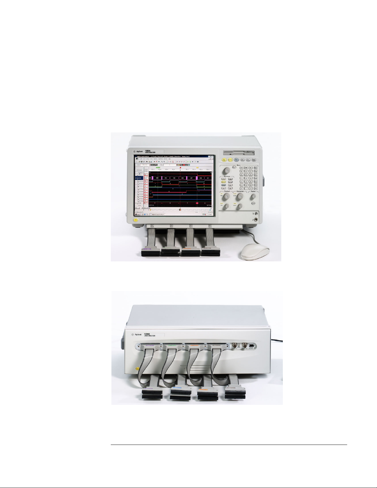
The Agilent 1680/90-Series Logic Analyzer–At a Glance
Features
Some of the main features of the Agilent 1680A,AD-Series Logic Analyzers are as
follows:
• Standalone benchtop logic analyzer
• Microsoft Windows® XP Professional operating system
• 132 data channels and 4 clock/data channels on the Agilent 1680A,AD
• 98 data channels and 4 clock/data channels on the Agilent 1681A,AD
• 64 data channels and 4 clock/data channels on the Agilent 1682A,AD
• 32 data channels and 2 clock/data channels on the Agilent 1683A,AD
• 12.1-inch LCD display
• 3.5-inch flexible disk drive
• 80GB hard disk drive
• Centronics and LAN interfaces
• IEEE 1394 interface for hosted control
• Variable setup/hold time
• 512K acquisition memory in the Agilent 1680A-series
• 2M acquisition memory in the Agilent 1680AD-series
•Marker Measurements
•PS/2 Mouse
• PS/2 keyboard support
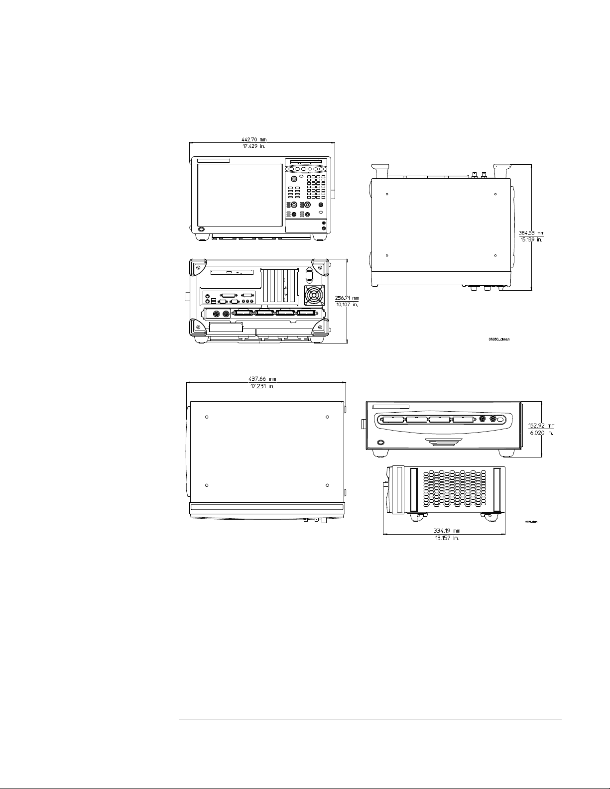
Some of the main features of the Agilent 1690A,AD-Series Logic Analyzers are as
follows:
• Hosted benchtop logic analyzer
• 132 data channels and 4 clock/data channels on the Agilent 1690A,AD
• 98 data channels and 4 clock/data channels on the Agilent 1691A,AD
• 64 data channels and 4 clock/data channels on the Agilent 1692A,AD
• 32 data channels and 2 clock/data channels on the Agilent 1693A,AD
• IEEE 1394 interface for hosted control
• Variable setup/hold time
• 512K acquisition memory in the Agilent 1690A-series
• 2M acquisition memory in the Agilent 1690AD-series
•Marker Measurements
2
Page 3
Service Strategy
The service strategy for this instrument is the replacement of defective
assemblies. This service guide contains information for finding a defective
assembly by testing and servicing the Agilent 1680/90-series logic analyzers.
This logic analyzer can be returned to Agilent for all service work, including
troubleshooting. Contact your nearest Agilent Technologies Sales Office for
details.
Agilent Technologies 1680-Series Logic Analyzer
Agilent Technologies 1690-Series Logic Analyzer
3
Page 4

In This Book
This book is the service guide for the Agilent 1680/90-Series Logic Analyzers and
is divided into eight chapters.
Chapter 1 contains information about the logic analyzer and includes accessories,
specifications and characteristics, and equipment required for servicing.
Chapter 2 tells how to prepare the logic analyzer for use.
Chapter 3 gives instructions on how to test the performance of the logic analyzer.
Chapter 4 contains calibration instructions for the logic analyzer.
Chapter 5 contains self-tests and flowcharts for troubleshooting the logic
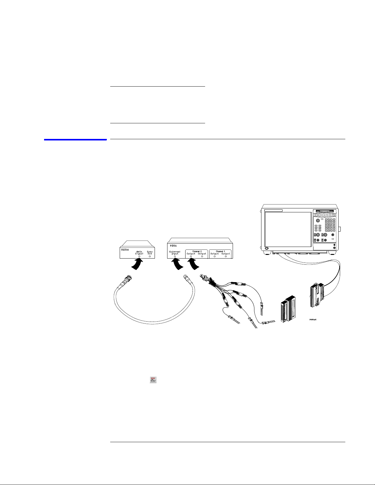
analyzer.
Chapter 6 tells how to replace assemblies of the logic analyzer and how to return
them to Agilent Technologies.
Chapter 7 lists replaceable parts, shows an exploded view, and gives ordering
information.
Chapter 8 explains how the logic analyzer works and what the self-tests are
checking.
4
Page 5

Contents
The Agilent 1680/90-Series Logic Analyzer–At a Glance
Features 2
Service Strategy 3
In This Book
1 General Information
Accessories 10
Specifications 11
Characteristics 11
Recommended Test Equipment 14
2 Preparing for Use
Power Requirements 16
Operating Environment 16
Storage 16
To inspect the logic analyzer 16
To apply power 17
To connect the 1690A,AD-series logic analyzer to a host PC 17
To start the user interface 18
To clean the logic analyzer 18
To test the logic analyzer 18
3 Testing Performance
The Logic Analyzer Interface 20
Test Strategy 20
Test Interval 20
Performance Test Record 20
Test Equipment 20
To make the test connectors 21
To set up the test equipment and the logic analyzer 23
Set up the test equipment 23
Set up the 1680A,AD-series logic analyzer 24
Set up the 1690A,AD-series logic analyzer 25
To perform the logic analyzer self-tests 25
5
Page 6

Contents
To test the threshold accuracy 28
Set up the equipment 28
Connect and configure the logic analyzer 29
Test the ECL Threshold 30
Test the 0 V User Threshold 31
Test the next pod 32
To set up the logic analyzer for the state mode tests 33
To test the single-clock, single-edge, state acquisition 37
Set up the equipment 37
Connect and configure the logic analyzer 37
Verify the test signal 40
Check the setup/hold combination 41
Test the next channels (1680/81A,AD and 1690/91A,AD) 47
To test the multiple-clock state acquisition 48
Set up the equipment 48
Connect and configure the logic analyzer 49
Verify the test signal 51
Check the setup/hold with single clock edges, multiple clocks 52
Test the next channels (1680/81A, AD and 1690/91A, AD) 56
To test the single-clock, multiple-edge, state acquisition 57
Set up the equipment 57
Connect and configure the logic analyzer 58
Verify the test signal 60
Check the setup/hold with single clock, multiple clock edges 61
Test the next channels (1680/81A,AD and 1690/91A,AD) 65
To test the time interval accuracy 66
Set up the equipment 66
Connect and configure the logic analyzer 67
Acquire and verify the test data 69
Performance Test Record 71
4 Calibrating and Adjusting
Logic analyzer calibration 76
6
Page 7

Contents
5 Troubleshooting
To install the fan guard 78
To use the flowcharts 79
Troubleshooting the Agilent 1680A,AD-series 80
To check the power-up tests 87
To test the power supply voltages 87
To test the LCD display signals 89
To test disk drive voltages 90
To verify the CD-ROM 92
To recover the operating system 93
Troubleshooting the Agilent 1690A,AD-series 95
To verify connectivity 99
To test the power supply voltages 100
General Troubleshooting 103
To run the self-tests 103
Acquisition board status LEDs 106
To test the logic analyzer probe cables 107
To check the BNC Trigger input/output signals 110
To test the auxiliary power 112
6 Replacing Assemblies
1680A,AD-series disassembly/assembly 114
Prepare the instrument for disassembly 114
To remove the chassis from the sleeve 114
To remove the acquisition board 115
To remove the power supply 117
To remove the hard disk drive 118
To remove the CD-ROM drive assembly 119
To remove the flexible disk drive 120
To remove the PCI boards 122
To remove the motherboard 123
To remove the front panel assembly 126
To disassemble the front panel assembly 128
To remove the distribution board 129
To remove the inverter board 130
To remove the fans 131
To remove the cable tray 132
7
Page 8

Contents
1690A,AD-series disassembly/assembly 133
Prepare the instrument for disassembly 133
To remove the chassis from the sleeve 133
To remove the fascia 134
To remove the acquisition board 136
To remove the deck 137
To remove the power supply 137
To remove the distribution board 138
To remove the fans 139
To remove the line filter 140
To remove the front panel and front frame 141
7 Replaceable Parts
Replaceable Parts Ordering 144
Replaceable Parts List 145
Exploded View 146
Agilent 1680A,AD-Series Replaceable Parts 147
Exploded View 153
Agilent 1690A,AD-Series Replaceable Parts 154
Power Cables and Plug Configurations 157
8 Theory of Operation
Block-Level Theory 160
Agilent 1680A,AD-series Logic Analyzer Theory 161
Power Supply 162
Acquisition Board 162
Power Distribution Board 165
Front Panel Board 165
Agilent 1690A,AD-series Logic Analyzer Theory 166
Acquisition Board 166
Power Supply 166
Power Distribution Board 166
Self-Tests Descriptions 167
Power-up Self-Tests (1680A,AD-series) 167
Connectivity Tests (1690A,AD-series) 167
Acquisition Board Self Tests 168
Logic Analyzer Self-Tests 169
8
Page 9

1
General Information
This chapter lists the accessories, the specifications and characteristics, and the
recommended test equipment.
9
Page 10

Chapter 1: General Information
Accessories
The following accessory is supplied with the Agilent 1680/90-series logic
analyzers. The part number is current as of the print date of this edition of the
Service Guide, but further upgrades may change the part number. Do not be
concerned if the accessory you receive has a different part number.
Accessories Supplied Agilent Part Number Qty
3-button Corded Mouse 1150-7845 1
Mini Keyboard 1150-7809 1
Accessories Available
For probing information, see Probing Solutions for Logic Analysis Systems
(publication 5968-4632E) available at:
http://www.agilent.com/find/logic_analyzer_probes
10
Page 11

Chapter 1: General Information
Specifications
The specifications are the performance standards against which the product is
tested.
Maximum State Speed (selectable) 200 MHz
Minimum Master to Master Clock Time* 5.000 ns
Threshold Accuracy ± (65 mV + 1.5% of threshold setting)
Setup/Hold Time
Single Clock, Single Edge 4.5/-2.0 ns through -2.0/4.5 ns, adjustable in 100 ps
Single Clock, Multiple Edges 5.0/-2.0 ns through -1.5/4.5 ns, adjustable in 100 ps
Multiple Clocks, Multiple Edges 5.0/-2.0 ns through -1.5/4.5 ns, adjustable in 100 ps
* Specified for an input signal VH = −0.9 V, VL = −1.7 V, slew rate = 1 V/ns, and threshold = −1.3 V.
*
increments
increments
increments
Characteristics
These characteristics are not specifications, but are included as additional
information.
Full Channel Half Channel
Maximum State Clock Rate 150 MHz not applicable
Maximum Conventional Timing Rate 250 MHz 500 MHz
Memory Depth (1680A, or 1690A-series) 512 K 1024 K
Memory Depth (1680AD or 1690AD-series) 2048 K 4196 K
Channel Count
1680A,AD or 1690A,AD 136 68
1681A,AD or 1691A,AD 102 51
1682A,AD or 1692A,AD 68 34
1683A,AD or 1693A,AD 34 17
11
Page 12

Chapter 1: General Information
Probes
Maximum Input Voltage + 40V Peak AC+DC, CAT 1
Auxiliary Power
Power Through Cables 1/3 amp at 5 V maximum per cable, CAT 1
Operating Environment (for indoor use only)
Temperat ure:
• Instrument: 0° C to 55° C (+32° F to 131° F).
• Probe lead sets and cables: 0° C to 65° C (+32° F to 149° F).
• Disk media: 10° C to 40° C (+50° F to 104° F).
Humidity: Instrument, probe lead sets, and cables, up to 80% relative humidity at
+40° C (+122° F).
Altitude: To 3067 m (10,000 ft).
Vibration:
• Operating: Random vibration 5 to 500 Hz, 10 minutes per axis, 0.3 g (rms).
• Non-operating: Random vibration 5 to 500 Hz, 10 minutes per axis, 2.41 g (rms); and
swept sine resonant search, 5 to 500 Hz, 0.75 g (0-peak), 5 minute resonant dwell at 4
resonances per axis.
12
Page 13
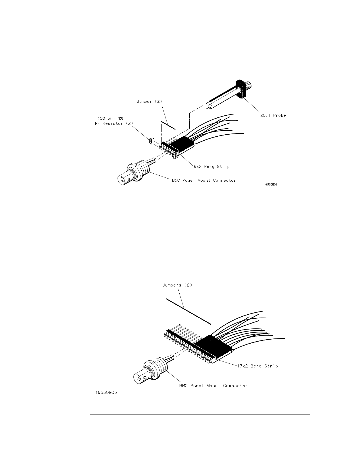
Dimensions
1680A,AD-Series
Chapter 1: General Information
1690A,AD-Series
13
Page 14

Chapter 1: General Information
Recommended Test Equipment
Equipment Required
Equipment Critical Specifications Recommended Model/Part
Pulse Generator 200 MHz, 2.5 ns pulse width,
8133A Option 003 P,T
Use
<600 ps rise time
Digitizing Oscilloscope ≥6 GHz bandwidth,
<58 ps rise time
Function Generator
Accuracy (5)(10
-6
) frequency,
54750A mainframe with 54751A
plug-in module
33250A P
P
DC offset voltage ±1.6 V
Digital Multimeter 0.1 mV resolution, 0.005%
3458A P
accuracy
BNC-Banana Cable 11001-60001 P
BNC Tee BNC (m)(f)(f) 1250-0781 P
Cable BNC (m)(m) 48 inch 8120-1840 P,T
SMA Coax Cable (Qty 3) 18 GHz bandwidth 8120-4948 P
Adapter (Qty 4) SMA(m)-BNC(f) 1250-1200 P, T
Adapter SMA(f)-BNC(m) 1250-2015 P
Coupler (Qty 4) BNC (m)(m) 1250-0216 P, T
20:1 Probes (Qty 2) 54006A P
BNC Coax Cable BNC(m)(m), >2 GHz
10503A T
bandwidth, >1 meter length
BNC Test Connector, 17x2 (Qty
**
1)
BNC Test Connector, 6x2 (Qty
**
4)
P
P, T
Digitizing Oscilloscope > 100 MHz Bandwidth 54600B T
BNC Shorting Cap 1250-0774 T
BNC-Banana Adapter 1251-2277 T
*
*A = Adjustment P = Performance Tests T = Troubleshooting
**Instructions for making these test connectors are in chapter 3, "Testing Performance."
14
Page 15

2
Preparing for Use
This chapter gives you instructions for preparing the logic analyzer for use.
15
Page 16

Chapter 2: Preparing for Use
Power Requirements
The logic analyzer requires a power source of either 115 Vac or 230 Vac, –22 % to
+10 %, single phase, 48 to 66 Hz, CAT II pollution degree 2, 140/400 Watts
nominal maximum power (1680A/AD-series), and 76/200 Watts nominal
maximum power (1690A/AD-series).
Operating Environment
The operating environment is listed in chapter 1. The logic analyzer will operate
at all specifications within the temperature and humidity range given in chapter
1. However, reliability is enhanced when operating the logic analyzer within the
following ranges:
• Temperature: +20° C to +35° C (+68° F to +95° F)
• Humidity: 20% to 80% noncondensing
Note the recommended noncondensing humidity. Condensation within the
instrument can cause poor operation or malfunction. Provide protection against
internal condensation.
Storage
Store or ship the logic analyzer in environments within the following limits:
• Temperature: -40° C to +75° C
• Humidity: Up to 90% at 65° C
• Altitude: Up to 15,300 meters (50,000 feet)
Protect the logic analyzer from temperature extremes which cause condensation
on the instrument.
To inspect the logic analyzer
1 Inspect the shipping container for damage.
If the shipping container or cushioning material is damaged, keep them until you
have checked the contents of the shipment and checked the instrument
mechanically and electrically.
2 Check the supplied accessories.
Accessories supplied with the logic analyzer are listed in “Accessories” on
page 10.
16
Page 17

Chapter 2: Preparing for Use
3 Inspect the product for physical damage.
Check the logic analyzer and the supplied accessories for obvious physical or
mechanical defects. If you find any defects, contact your nearest Agilent
Technologies Sales Office. Arrangements for repair or replacement are made, at
Agilent Technologies' option, without waiting for a claim settlement.
To apply power
These steps are required for all 1680A,AD and 1690A,AD-series logic analyzers.
1 Connect the power cord to the instrument and to the power source.
This instrument autodetects the line voltage from 115 VAC to 230 VAC. It is
equipped with a three-wire power cable. When connected to an appropriate AC
power outlet, this cable grounds the instrument cabinet. The type of power cable
plug shipped with the instrument depends on the country of destination. Refer to
chapter 7, "Replaceable Parts," for option numbers of available power cables.
2 Turn on the power switch located on the front panel.
To connect the 1690A,AD-series logic analyzer to a host PC
These steps are required for the Agilent 1690A,AD-series hosted logic analyzer.
The logic analyzer user interface requires a host computer (PC) with the
following characteristics (or better):
Intel Celeron, AMD K6-II 500 MHz
Windows 2000 Professional or Windows XP Professional
128MB RAM
IEEE 1394 PCI card
1 Connect one end of the 6-pin IEEE 1394 cable to the IEEE 1394 port on
the host PC.
2 Connect the free end of the IEEE 1394 cable to the IEEE 1394 port on the
logic analyzer.
3 Apply power to the PC if it is not turned on.
17
Page 18

Chapter 2: Preparing for Use
To start the user interface
Start the Agilent Logic Analyzer application from the Start menu or using a
shortcut. On the desktop, the Agilent Logic Analyzer icon looks like:
Refer to the Agilent Logic Analyzer on-line help for information on how to
operate the user interface. Also, refer to the window icon reference on the inside
front cover of this service manual for a brief explanation of the Agilent Logic
Analyzer standard icons.
To clean the logic analyzer
With the instrument turned off and unplugged, use mild soap and water to clean
the front and cabinet of the logic analyzer. Harsh soap might damage the waterbase paint.
To test the logic analyzer
• If you require a test to verify the specifications, start at the beginning of
chapter 3, "Testing Performance."
• If you require a test to initially accept the operation, perform the self-tests
in chapter 3.
• If the logic analyzer does not operate correctly, go to the beginning of
chapter 5, "Troubleshooting."
18
Page 19

3
Testing Performance
This chapter tells you how to test the performance of the logic analyzer against
the specifications listed in chapter 1.
19
Page 20

Chapter 3: Testing Performance
The Logic Analyzer Interface
To select a field on the logic analyzer screen, use the arrow keys to highlight the
field, then press the Select key. Provided on the inside front cover of this manual
is a list of logic analyzer icons that can be referenced while performing test
procedures. For more information about the logic analyzer interface, refer to the
Agilent Logic Analyzer application’s online help.
Test Strategy
For a complete test, start at the beginning with the software tests and continue
through to the end of the chapter. For an individual test, follow the procedure in
the test. The examples in this chapter were performed using an Agilent 1680AD.
Other analyzers in the series will have appropriate pods showing on the screen.
The performance verification procedures starting on page 3–8 are each shown
from power-up. To exactly duplicate the setups in the tests, save the power-up
configuration to a file on a disk, then load that file at the start of each test.
If a test fails, check the test equipment setup, check the connections, and verify
adequate grounding. If a test still fails, the most probable cause of failure would
be the acquisition board.
Test Interval
Test the performance of the logic analyzer against specifications at two-year
intervals.
Performance Test Record
A performance test record for recording the results of each procedure is located
at the end of this chapter. Use the performance test record to gauge the
performance of the logic analyzer over time.
Test Equipment
Each procedure lists the recommended test equipment. You can use equipment
that satisfies the specifications given. However, the procedures are based on
using the recommended model or part number. Before testing the performance
of the logic analyzer, warm-up the instrument and the test equipment for 30
minutes.
20
Page 21

Chapter 3: Testing Performance
To make the test connectors
To make the test connectors
The test connectors connect the logic analyzer to the test equipment.
Materials Required
Description Recommended Part Qty
BNC (f) Connector 1250-0698 5
100 Ω 1% resistor 0698-7212 8
Berg Strip, 17-by-2 1
Berg Strip, 6-by-2 4
20:1 Probe 54006A 2
Jumper wire
1 Build four test connectors using BNC connectors and 6-by-2 sections of
Berg strip:
a Solder a jumper wire to all pins on one side of the Berg strip.
b Solder a jumper wire to all pins on the other side of the Berg strip.
c Solder two resistors to the Berg strip, one at each end between the end
pins.
d Solder the center of the BNC connector to the center pin of one row on
the Berg strip.
e Solder the ground tab of the BNC connector to the center pin of the
other row on the Berg strip.
21
Page 22
Chapter 3: Testing Performance
To make the test connectors
f On two of the test connectors, solder a 20:1 probe. The probe ground
goes to the same row of pins on the test connector as the BNC ground
tab.
2 Build one test connector using a BNC connector and a 17-by-2 section of
Berg strip:
a Solder a jumper wire to all pins on one side of the Berg strip.
b Solder a jumper wire to all pins on the other side of the Berg strip.
c Solder the center of the BNC connector to the center pin of one row on
the Berg strip.
d Solder the ground tab of the BNC connector to the center pin of the
other row on the Berg strip.
22
Page 23

Chapter 3: Testing Performance
To set up the test equipment and the logic analyzer
To set up the test equipment and the logic analyzer
Before testing the specifications of the Agilent 1680A,AD-series or 1690A,ADseries logic analyzer, the test equipment and the logic analyzer must be set up
and configured.
These instructions include detailed steps for initially setting up the required test
equipment and the logic analyzer. Before performing any or all of the tests in this
chapter, the following steps must be done.
Equipment Required
Equipment Critical Specifications
Pulse Generator 200 Mhz, 2.5 ns pulse width, <600 ps rise time 8133A option 003
Digitizing Oscilloscope ≥ 6 GHz bandwidth, < 58 ps rise time 54750A w/ 54751A
Digital Multimeter 0.1 mV resolution, 0.005% accuracy 3458A
Function Generator DC offset voltage ±1.5 V 3325B Option 002
Recommended HP/Agilent
Model/Part
Set up the test equipment
1 Turn on the required test equipment listed in the table above. Let them
warm up for 30 minutes before beginning any test.
2 Set up the pulse generator according to the following table.
Pulse Generator Setup
Timebase Channel 2 Trigger Channel 1
Mode: Int
Period: 5.000 ns
Mode: Pulse
Divide: Pulse ÷ 2
Width: 2.500 ns
Ampl: 0.80 V
Offs: -1.30 V
COMP: Disabled
(LED Off)
Divide: Divide ÷ 2
Ampl: 0.50 V
Offs: 0.00 V
Mode: Square
Delay: 0.0 ps
Ampl: 0.80 V
Offs: -1.30 V
COMP: Disabled
(LED Off)
3 Set up the oscilloscope:
a Select Setup, then select Default Setup.
23
Page 24

Chapter 3: Testing Performance
To set up the test equipment and the logic analyzer
b Configure the oscilloscope according to the following table.
Oscilloscope Setup
Acquisition Display Trigger [Shift] ∆ Time
Averaging: On
# of averages: 16
Channel 1 Channel 2 Define meas
Graticule graphs: 2 Level: 0.0 V Stop src: channel 2 [Enter]
External Scale
Attenuation: 20.00:1
Scale: 200 mV/div
Offset: - 1.300 V
External Scale
Attenuation: 20.00:1
Scale: 200 mV/div
Offset: - 1.300 V
Thresholds: user-defined
Units: Volts
Upper: - 980 mV
Middle: -1.30 V
Lower: -1.62 V
Set up the 1680A,AD-series logic analyzer
Power-up self tests are done on the logic analyzer system components when
power is applied. Any problems reported by the logic analyzer during boot must
be cleared before going further. For more information, refer to Chapter 5 and
Chapter 8.
1 Turn on the logic analyzer:
a Connect a keyboard and mouse to the rear panel of the logic analyzer.
b Plug in a power cord to the rear panel power connector of the logic
analyzer.
c Turn on the power switch on the logic analyzer front panel.
2 Set up the logic analyzer:
a Wait for the logic analyzer boot up to complete.
b On the logic analyzer desktop, double-click the Agilent Logic Analyzer
icon to launch the application.
24
Page 25

Chapter 3: Testing Performance
To set up the test equipment and the logic analyzer
Set up the 1690A,AD-series logic analyzer
Power-up self tests are done on the logic analyzer system components when
power is applied. Logic analyzer peripheral communication tests are done when
the host PC recognizes the hosted logic analyzer hardware. Any problems
reported should be cleared before going further. For more information, refer to
Chapter 5 and Chapter 8.
1 Connect the logic analyzer to the host PC.
2 Set up the logic analyzer:
a Wait for the logic analyzer power-up to complete.
b On the host PC desktop, double-click the Agilent Logic Analyzer icon to
launch the application.
c In the Agilent Logic Analyzer application window, ensure the
application reports “Online.”
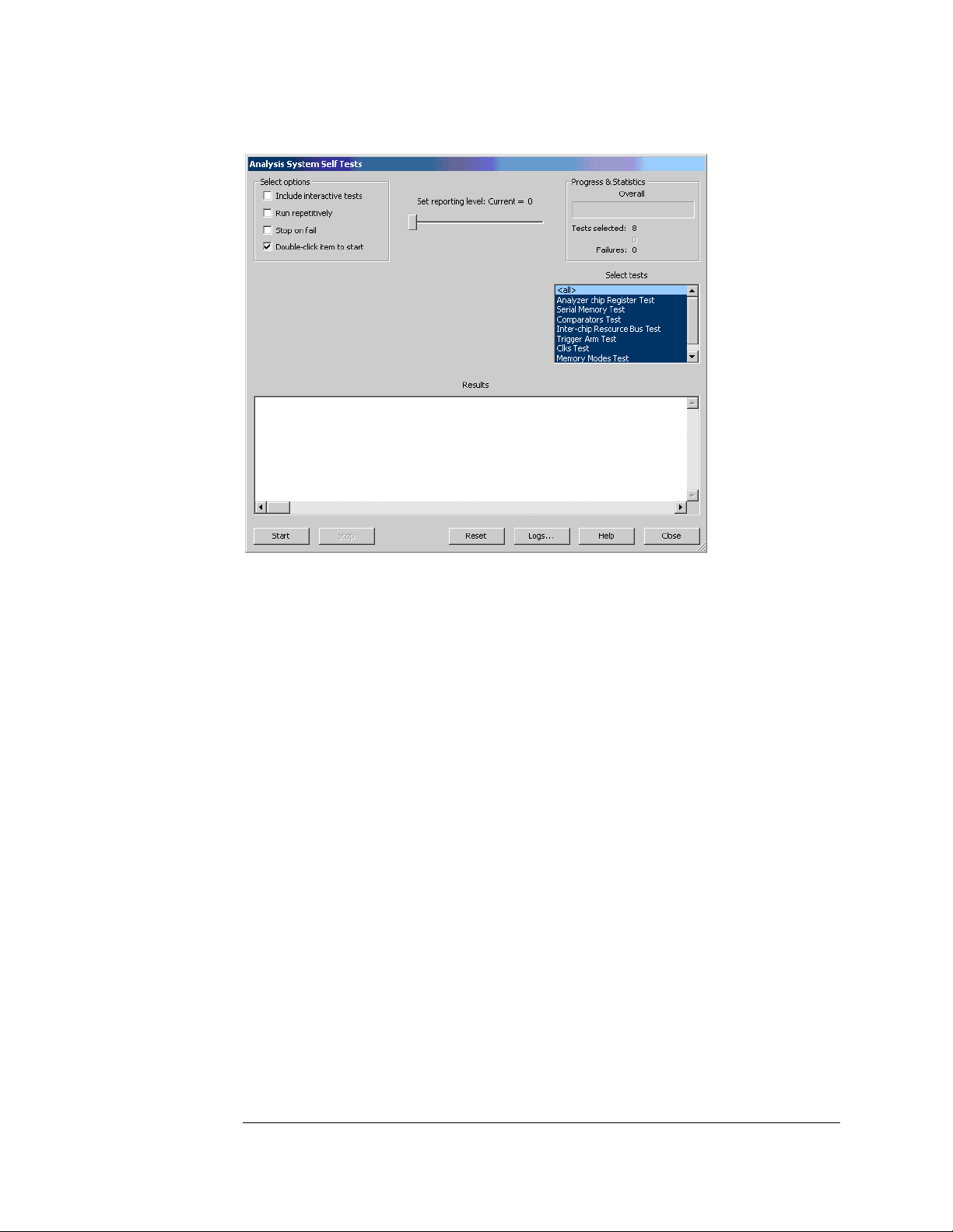
To perform the logic analyzer self-tests
The Self Test menu checks the major hardware functions of the logic analyzer to
verify that it is working correctly. Self-tests can be performed all at once or one at
a time. While testing the performance of the logic analyzer, run the self-tests all at
once. Refer to Chapter 8 for more information on the logic analyzer self-tests.
CAUTION: Because the most recently acquired data will be lost, be sure to save important data
before running self tests.
1 In the Agilent Logic Analyzer application, choose Help>Self Test... from
the main menu.
CAUTION: If you have acquired data, a warning message appears, "Running self-tests will invalidate
acquired data"; click OK to continue.
25
Page 26
Chapter 3: Testing Performance
To set up the test equipment and the logic analyzer
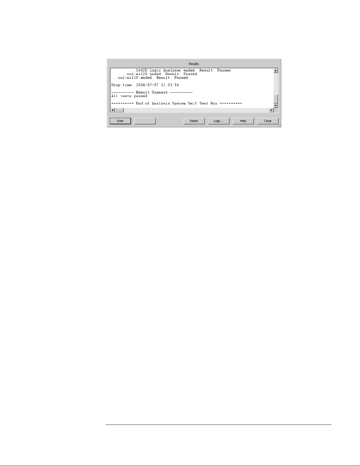
2 In the Analysis System Self Tests dialog, select the self test options:
• Include interactive tests — causes interactive tests to appear in the selection lists.
• Run repetitively — runs the selected tests repetitively until you click Stop.
• Stop on fail — if you are running multiple tests or running tests repetitively, this
causes the tests to stop if there is a failure.
• Double-click item to start — lets you double-click a test to start it.
3 Set the reporting level.
Higher levels produce increasingly verbose output.
4 Select the tests you want to run.
5 Click Start.
As the tests are running, the results are reported in the lower part of the dialog
and saved to a log file.
26
Page 27
Chapter 3: Testing Performance
To set up the test equipment and the logic analyzer
To stop running test, click Stop.
To reset the self-test options, click Reset.
To view the log file, click Logs..., select the log file you want to view, and click
Open.
If, after completing the self tests, you have failures or you have questions about
the performance of the logic analysis system, contact Agilent Technologies sales
or support at http://www.agilent.com/find/contactus.
6 Click Close to close the Analysis System Self Tests dialog.
27
Page 28

Chapter 3: Testing Performance
To test the threshold accuracy
To test the threshold accuracy
Testing the threshold accuracy verifies the performance of the following
specification:
• Clock and data channel threshold accuracy.
These instructions include detailed steps for testing the threshold settings of
pod 1. After testing pod 1, connect and test the rest of the pods one at a time. To
test the next pod, follow the detailed steps for pod 1, substituting the next pod
for pod 1 in the instructions.
Each threshold test tells you to record a pass/fail reading in the performance test
record located at the end of this chapter.
Equipment Required
Equipment Critical Specifications Recommended Model/Part
Digital Multimeter 0.1 mV resolution, 0.005% accuracy 3458A
Function Generator
BNC-Banana Cable 11001-60001
BNC Tee 1250-0781
BNC Cable 8120-1840
BNC Test Connector, 17x2
Accuracy (5)(10
DC offset voltage ±1.5 V
-6
) frequency,
33250A
Set up the equipment
1 If you have not already done so, do the procedure “To set up the test
equipment and the logic analyzer” on page 23.
2 Set up the DC source to deliver a DC voltage on the output:
a In the function generator Utility menu, activate the DC Level. All AC
voltage functions will be disabled.
b Enable the high impedance load under the Output Setup menu.
3 Using a BNC-banana cable, connect the voltmeter to one side of the BNC
Tee.
4 Connect the BNC Tee to the output of the DC source. Set up the logic
analyzer.
28
Page 29
Chapter 3: Testing Performance
To test the threshold accuracy
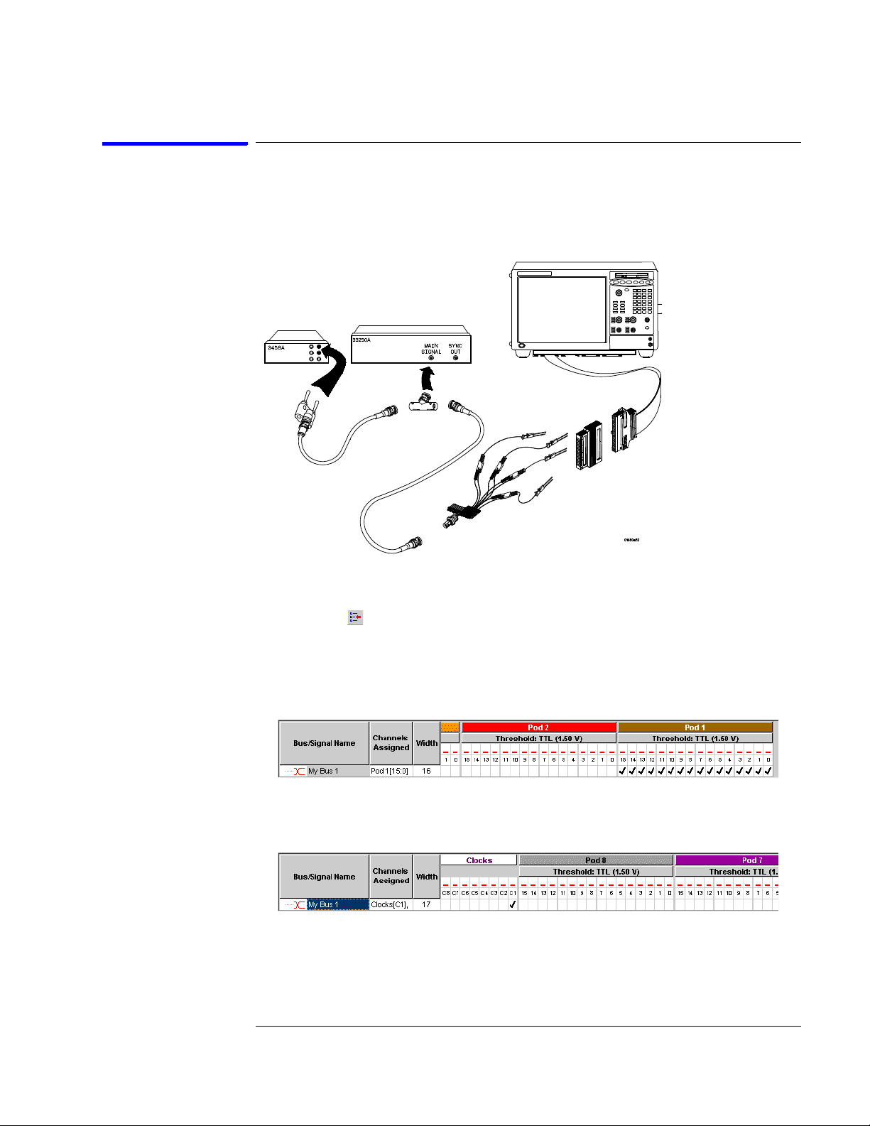
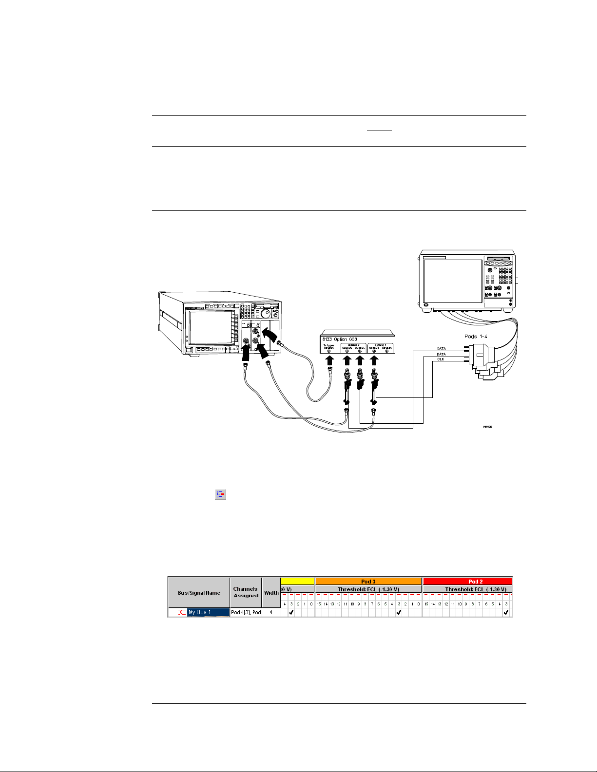
Connect and configure the logic analyzer
1 Using the 17-by-2 test connector, BNC cable, and probe tip assembly,
connect the data and clock channels of Pod 1 to the free side of the BNC
Tee.
2 Configure the logic analyzer:
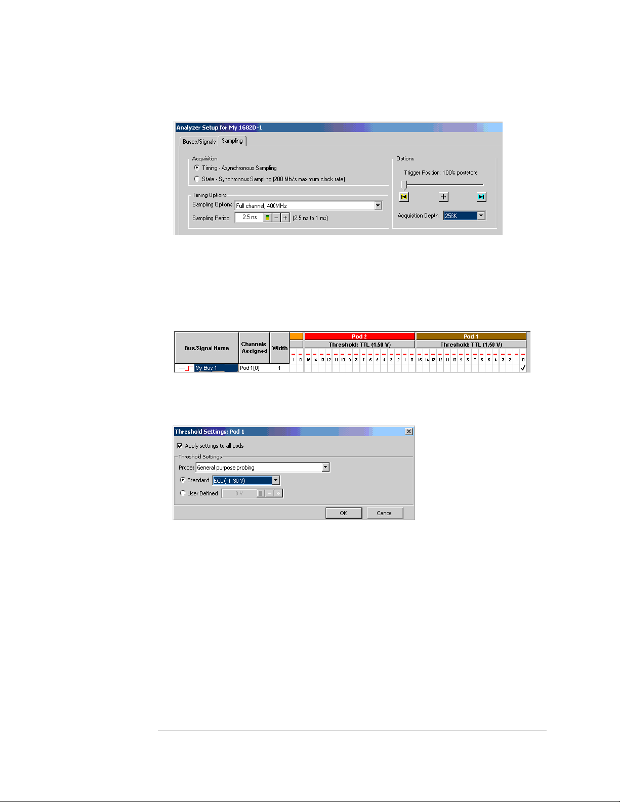
a Click the Bus/Signal Setup icon. The Analyzer Setup dialog opens.
b In the Buses/Signals tab, click Delete All at the bottom of the dialog.
c Using the mouse, activate all Pod 1 channels. Assign channels to bus/
signal name My Bus 1.
d Scroll the channel assignments to the left. Assign the clock/data
channel for the Pod 1 (that is, C1) to My Bus 1.
3 Activate the DC source output.
29
Page 30
Chapter 3: Testing Performance
To test the threshold accuracy
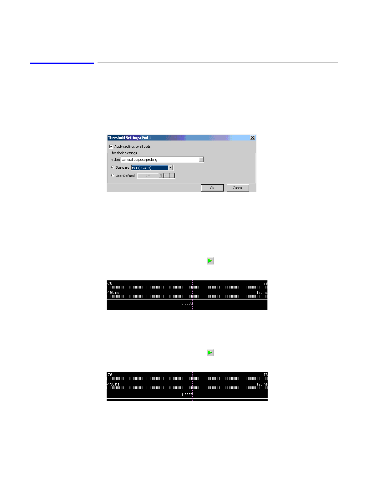
Test the ECL Threshold
1 Set up the logic analyzer:
a In the Analyzer Setup dialog, click the threshold field for Pod 1. The
Threshold Settings dialog appears.
b In the Threshold Settings dialog, select Standard and ECL (–1.30 V).
c Click OK to close the Threshold Settings dialog.
d Click OK to close the Analyzer Setup dialog.
2 Test the high-to-low transition:
a On the DC source, enter a voltage setting of –1.384 V.
b On the logic analyzer, click the Run icon. The display should show all
channels at a logic "0".
3 Test the low-to-high transition:
a On the DC source, enter a voltage setting of –1.216 V.
b On the logic analyzer, click the Run icon. The display should show all
channels at a logic "1" (0x1FFFF).
4 Record a PASS/FAIL in the performance test record for Threshold
Accuracy Pod 1 - ECL.
30
Page 31

Chapter 3: Testing Performance
To test the threshold accuracy
Test the 0 V User Threshold
1 Set up the logic analyzer:
a On the logic analyzer, click the Bus/Signal Setup icon. The Analyzer
Setup dialog opens.
b In the Analyzer Setup dialog, click the threshold field for Pod 1. The
Threshold Settings dialog appears.
c In the Threshold Settings dialog, select User Defined and enter 0 V in
the associated field.
d Click OK to close the Threshold Settings dialog.
e Click OK to close the Analyzer Setup dialog.
2 Test the high-to-low transition:
a On the DC source, enter a voltage setting of –0.064 V.
b On the logic analyzer, click the Run icon. The display should show all
channels at a logic "0".
3 Test the low-to-high transition:
a On the DC source, enter a voltage setting of 0.064 V.
b On the logic analyzer, click the Run icon. The display should show all
channels at a logic "1" (0x1FFFF).
4 Record a PASS/FAIL in the performance test record for Threshold
Accuracy Pod 1 - User 0 V.
31
Page 32

Chapter 3: Testing Performance
To test the threshold accuracy
Test the next pod
1 Using the 17-by-2 test connector and probe tip assembly, connect the data
and clock channels of the next pod to the output of the function generator
until all pods have been tested.
2 Start with “Connect and configure the logic analyzer” on page 29
substituting the next pod to be tested for pod 1.
32
Page 33
Chapter 3: Testing Performance
To set up the logic analyzer for the state mode tests
To set up the logic analyzer for the state mode tests
1 Set up the logic analyzer:
a If you have not already done so, do the procedure “To set up the test
equipment and the logic analyzer” on page 23.
b Exit and restart the Agilent Logic Analyzer application to reinitialize
the logic analyzer.
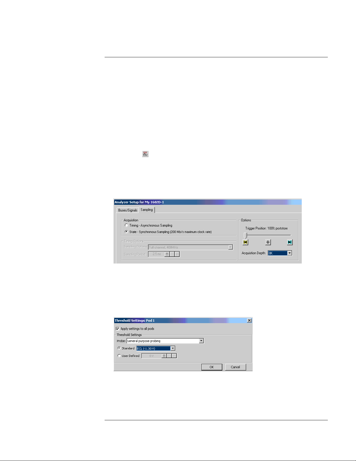
2 Configure the Analyzer Setup dialog:
a Click the Sampling Setup icon.
b Select State - Synchronous Sampling.
c Configure Trigger Position - 100% poststore.
d Select an Acquisition Depth of 8K.
e Click the Buses/Signals tab.
f Click the threshold field of one of the pods. The Threshold Settings
dialog appears.
g In the Threshold Settings dialog, select Standard and ECL (–1.30 V).
h Click OK to close the Threshold Settings dialog.
i Click OK to close the the Analyzer Setup dialog.
33
Page 34
Chapter 3: Testing Performance
To set up the logic analyzer for the state mode tests
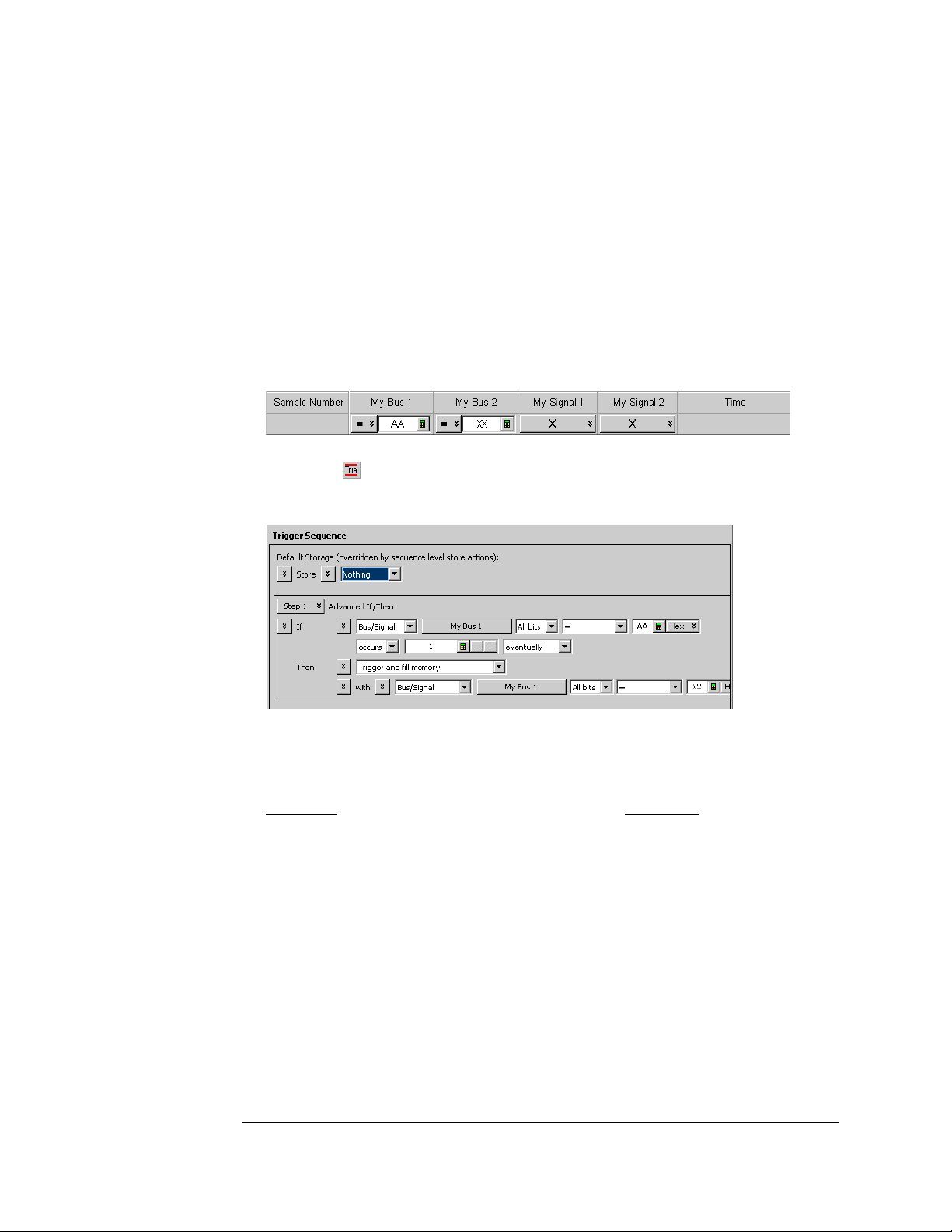
3 Configure the trigger according to your logic analyzer:
a In the Listing window, click on the trigger pattern field for My Bus 1 to
select.
b Enter the following pattern for your logic analyzer.
1680A,AD, 1690A,AD - "AA"
1681A,AD, 1691A,AD - "2A"
1682A,AD, 1692A,AD - "AA"
1683A,AD, 1693A,AD - "A"
c Click the Trigger Setup icon.
d For the Default Storage, select Store Nothing.
e Click OK to close the Advanced Trigger dialog.
4 Activate the pulse generator data and clock outputs:
a On the pulse generator, enable the channel 1 OUTPUT, channel 1
OUTPUT
, channel 2 OUTPUT and channel 2 OUTPUT (LEDs off)
b On the pulse generator, enable the trigger OUTPUT. (LED off)
5 Set up the Markers:
The following procedure is done after the first run of test data is acquired (during
one of the state clock mode tests).
a From the main menu, choose Markers>Properties....
b In the Marker Properties tab of the Listing Viewer Properties dialog,
34
Page 35
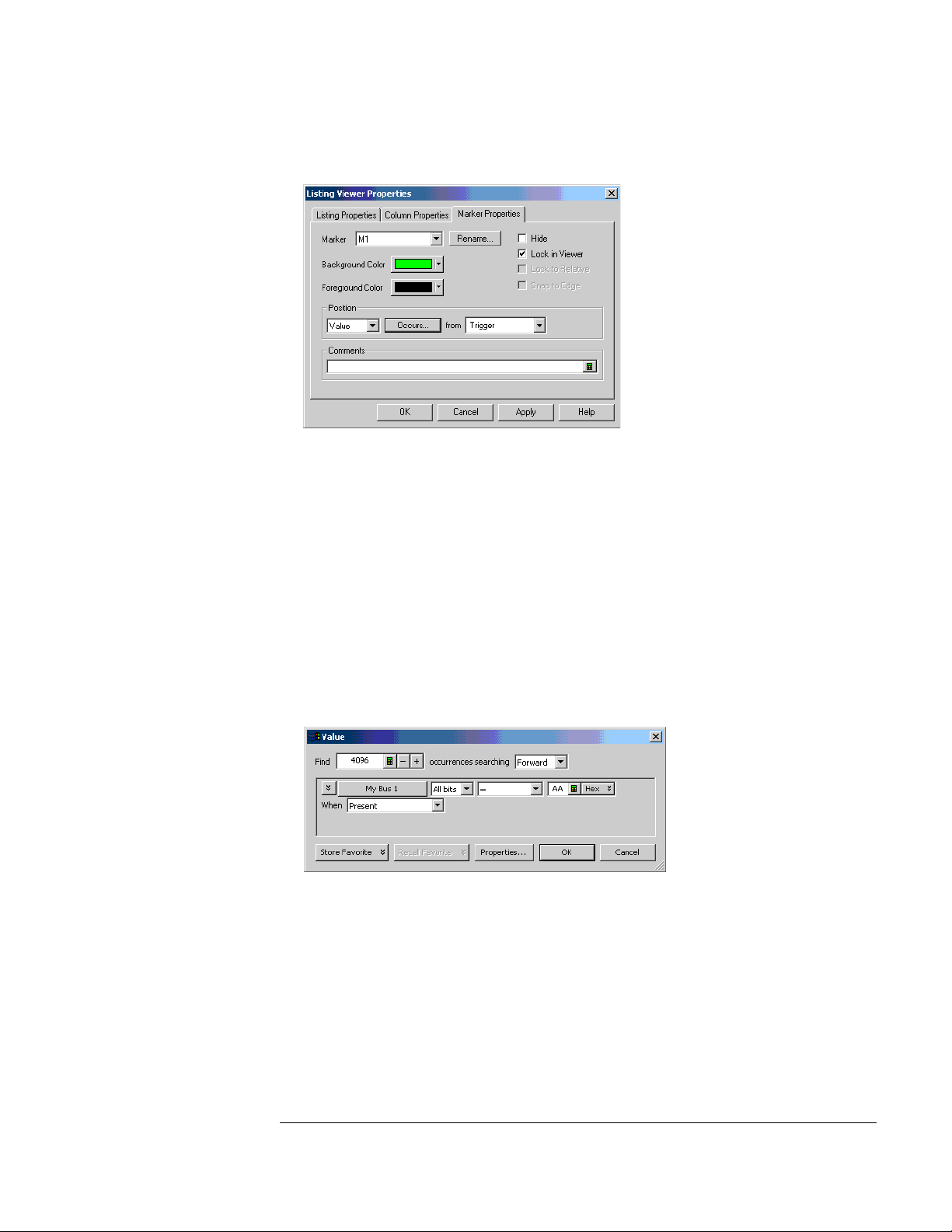
Chapter 3: Testing Performance
To set up the logic analyzer for the state mode tests
select the M1 marker.
c In the Position box, select Value.
d Click on the Occurs... button and the Value dialog appears.
e Click on the Find occurrences field, and enter 4096.
f Click on the pattern field, then enter the following pattern according to
the logic analyzer being tested:
1680A,AD, 1690A,AD - "AA"
1681A,AD, 1691A,AD - "2A"
1682A,AD, 1692A,AD - "AA"
1683A,AD, 1693A,AD - "A"
g Click OK to close the Value dialog.
35
Page 36
Chapter 3: Testing Performance
To set up the logic analyzer for the state mode tests
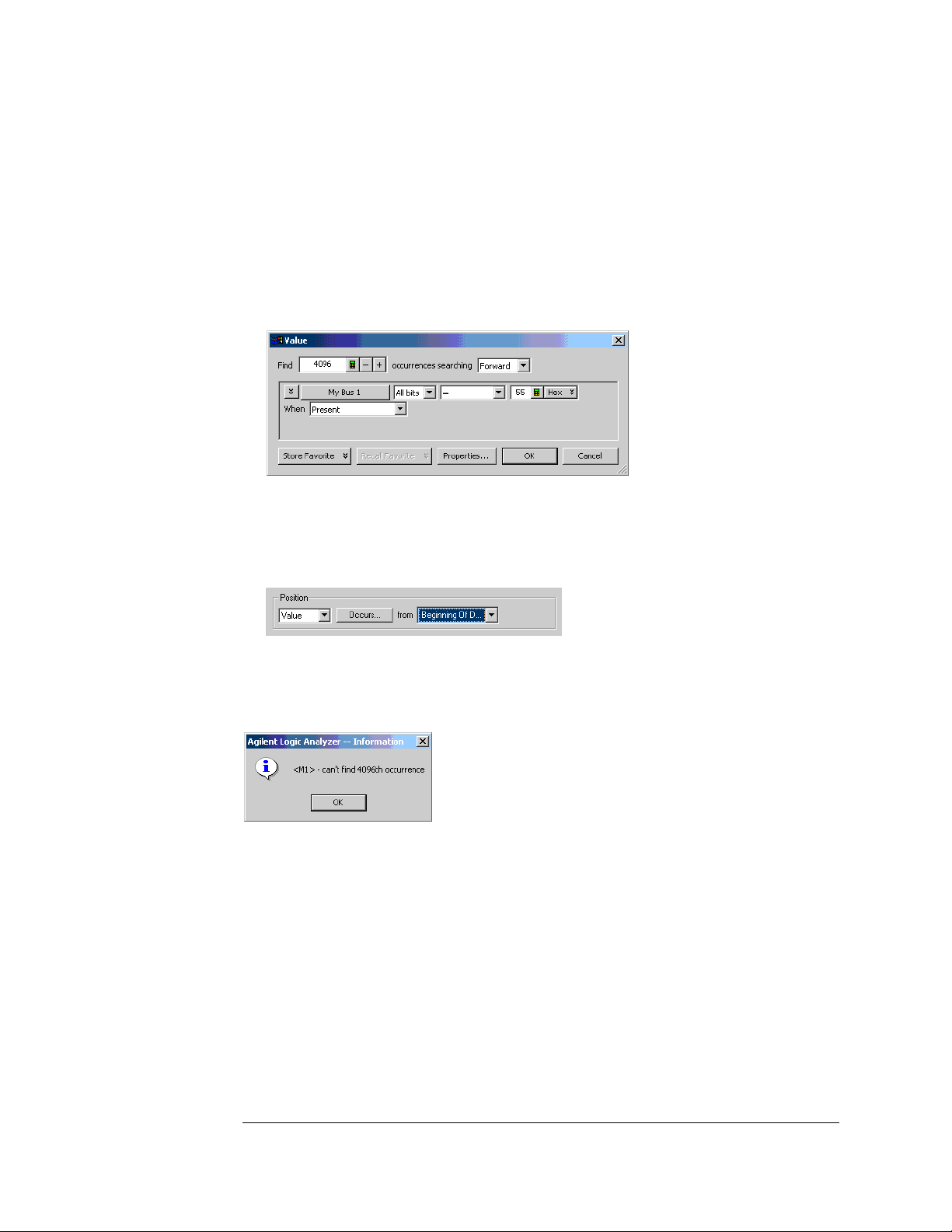
h Repeat steps b through f to configure marker M2 using the following
pattern according to the logic analyzer being tested.
1680A,AD, 1690A,AD - "55"
1681A,AD, 1691A,AD - "15"
1682A,AD, 1692A,AD - "55"
1683A,AD, 1693A,AD - "5"
i Click OK to close the Value dialog.
j In the Listing Viewer Properties dialog, select Beginning Of Data in the
“from” field.
The logic analyzer markers are now configured to verify the test data. If the error
message "can't find 4096 occurence(s)" does not appear, the test passes. Click
OK to close the Listing ViewerProperties dialog
When the above error message appears, one or more samples of test data is
incorrect. When this happens, check the following and attempt the test again:
• All cables are properly connected.
• Configuration of each test equipment is correct.
• Logic analyzer is properly set up according to the test procedure.
36
Page 37

Chapter 3: Testing Performance
To test the single-clock, single-edge, state acquisition
To test the single-clock, single-edge, state acquisition
Testing the single-clock, single-edge, state acquisition verifies the performance of
the following specifications:
• Minimum master-to-master clock time.
• Maximum state acquisition speed.
• Setup/Hold time for single-clock, single-edge, state acquisition.
This test checks two combinations of data channels using a single-edge clock at
two selected setup/hold times.
Equipment Required
Equipment Critical Specifications Recommended Model/Part
Pulse Generator 200 MHz 2.5 ns pulse width, <600 ps rise time 8133A option 003
Digitizing Oscilloscope ≥6 GHz bandwidth, <58 ps rise time 54750A w/ 54751A
Adapter SMA(m)-BNC(f) 1250-1200
SMA Coax Cable (Qty 3) 18 GHz bandwidth 8120-4948
Coupler BNC(m)(m) 1250-0216
BNC Test Connector,
6x2 (Qty 4)
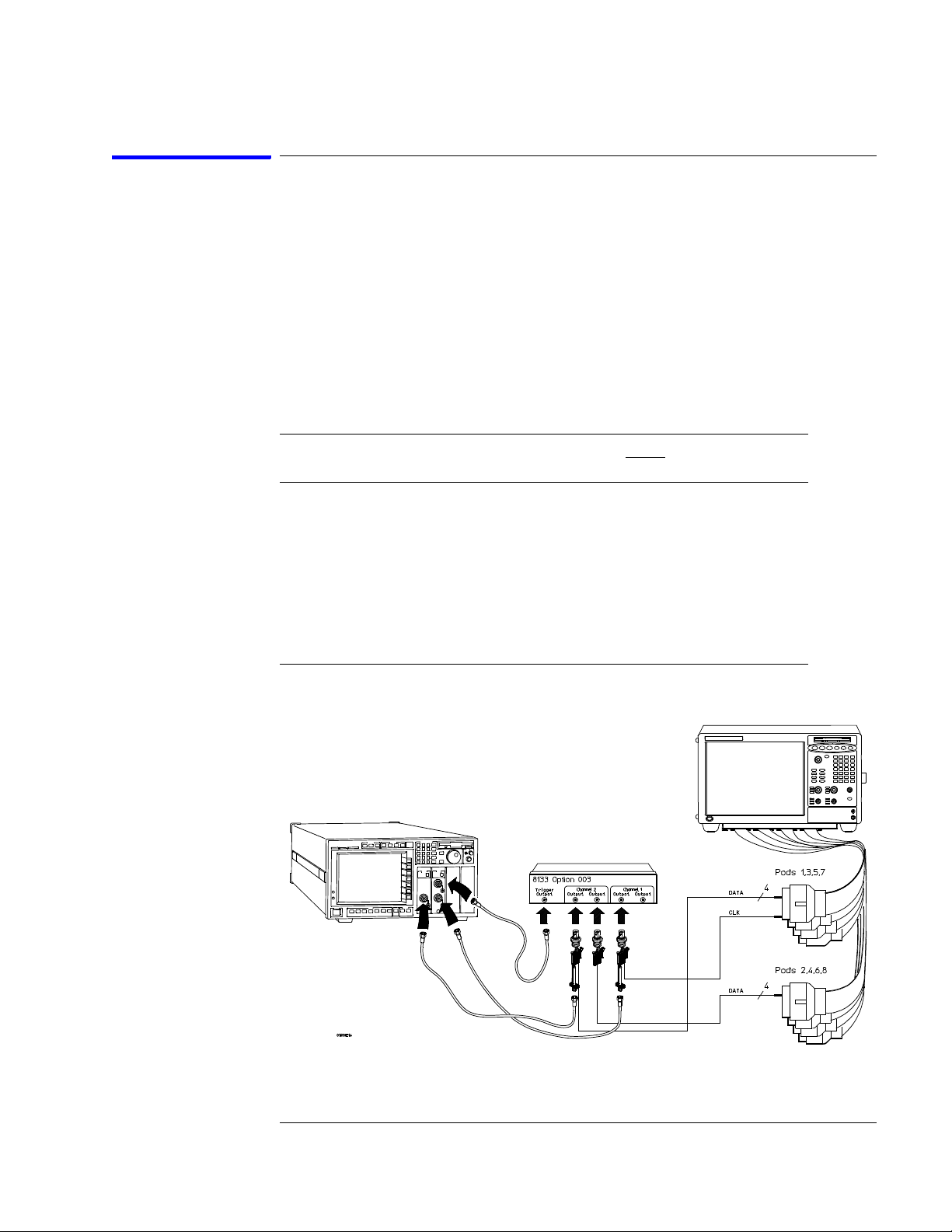
Set up the equipment
If you have not already done so, do the following procedures:
“To set up the test equipment and the logic analyzer” on page 23.
“To set up the logic analyzer for the state mode tests” on page 33.
Connect and configure the logic analyzer
1 Using the 6-by-2 test connectors, connect the first combination of logic
analyzer clock and data channels listed in one of the following tables to the
pulse generator.
If you are testing a 1680/81/90/91A,AD, you will repeat this test for the second
combination.
37
Page 38
Chapter 3: Testing Performance
To test the single-clock, single-edge, state acquisition
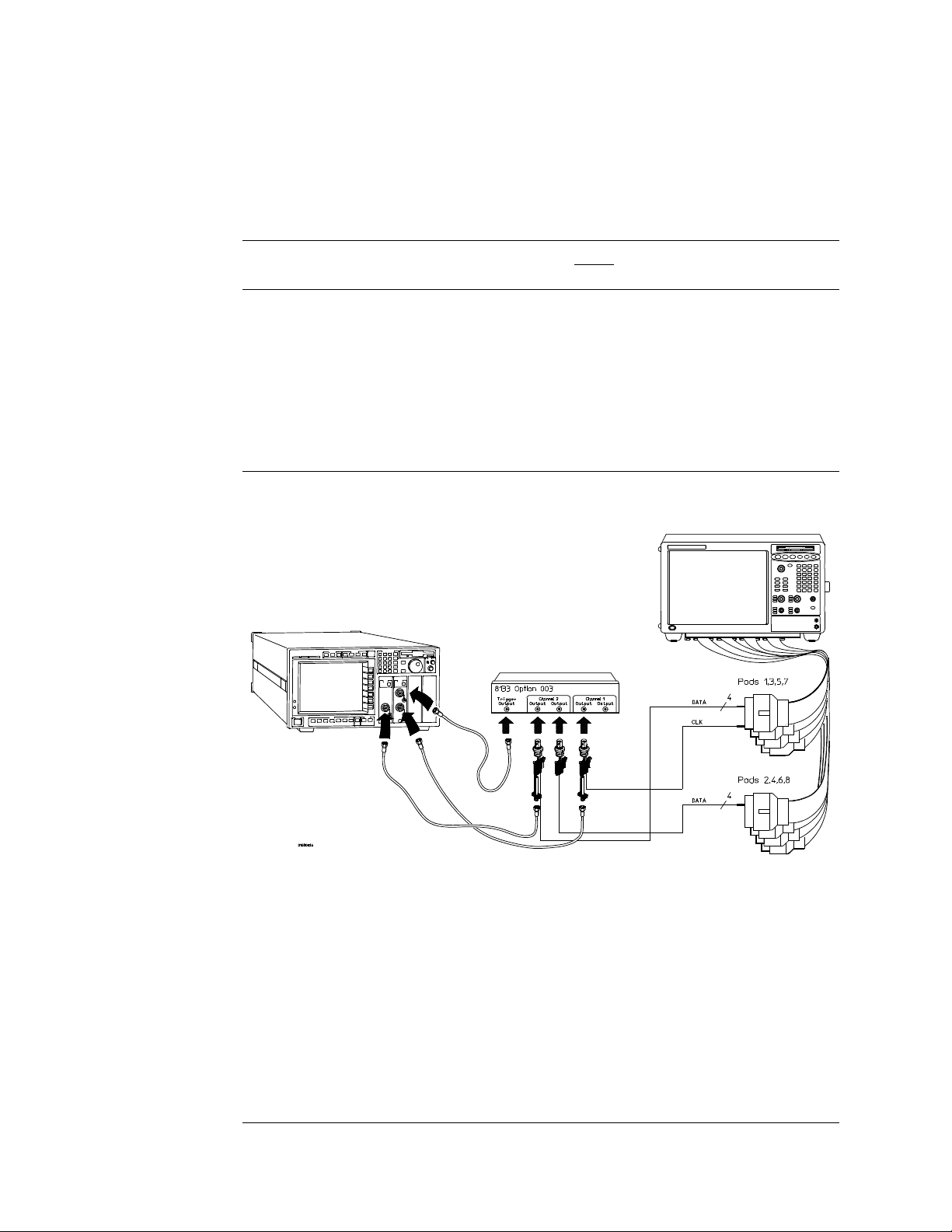
2 Using SMA cables, connect the oscilloscope to the pulse generator channel
1 Output, channel 2 Output, and Trigger Output.
Connect the 1680/81/90/91A,AD Logic Analyzer to the Pulse Generator
Te s t i n g
Combinations
1 Pod 1, channel 3
2 Pod 1, channel 11
*1680A,AD or 1690A,AD only
Connect to 8133A
Channel 2 Output
Pod 3, channel 3
Pod 5, channel 3
Pod 7, channel 3
Pod 3, channel 11
Pod 5, channel 11
Pod 7, channel 11
Connect to 8133A
Channel 2 Output
Pod 2, channel 3
Pod 4, channel 3
Pod 6, channel 3
Pod 8, channel 3 *
Pod 2, channel 11
Pod 4, channel 11
Pod 6, channel 11
Pod 8, channel 11*
Connect to 8133A
Channel 1 Output
Pod 1 clock/data channel (Clk 1)
Pod 1 clock/data channel (Clk 1)
38
Page 39

Chapter 3: Testing Performance
To test the single-clock, single-edge, state acquisition
Connect the 1682/83/92/93A,AD Logic Analyzer to the Pulse Generator
Tes ti ng
Combination
1 Pod 1, channel 3
*1682A,AD or 1692A,AD only.
Connect to 8133A
Channel 2 Output
Pod 2, channel 3
Pod 3, channel 3
Pod 4, channel 3
Connect to 8133A
Channel 2 Output
Pod 1, channel 11
Pod 2, channel 11
Pod 3, channel 11*
Pod 4, channel 11*
Connect to 8133A
Channel 1 Output
Pod 1 clock/data channel (Clk 1)
3 Activate the data channels that are connected according to one of the
previous tables:
a Click on the Bus/Signal Setup icon. The Analyzer Setup dialog opens.
b In the Buses/Signals tab, click Delete All at the bottom of the dialog.
c Using the mouse, activate the data channels being tested. Assign
channels to bus/signal name My Bus 1.
d Click OK to close the Analyzer Setup dialog.
39
Page 40

Chapter 3: Testing Performance
To test the single-clock, single-edge, state acquisition
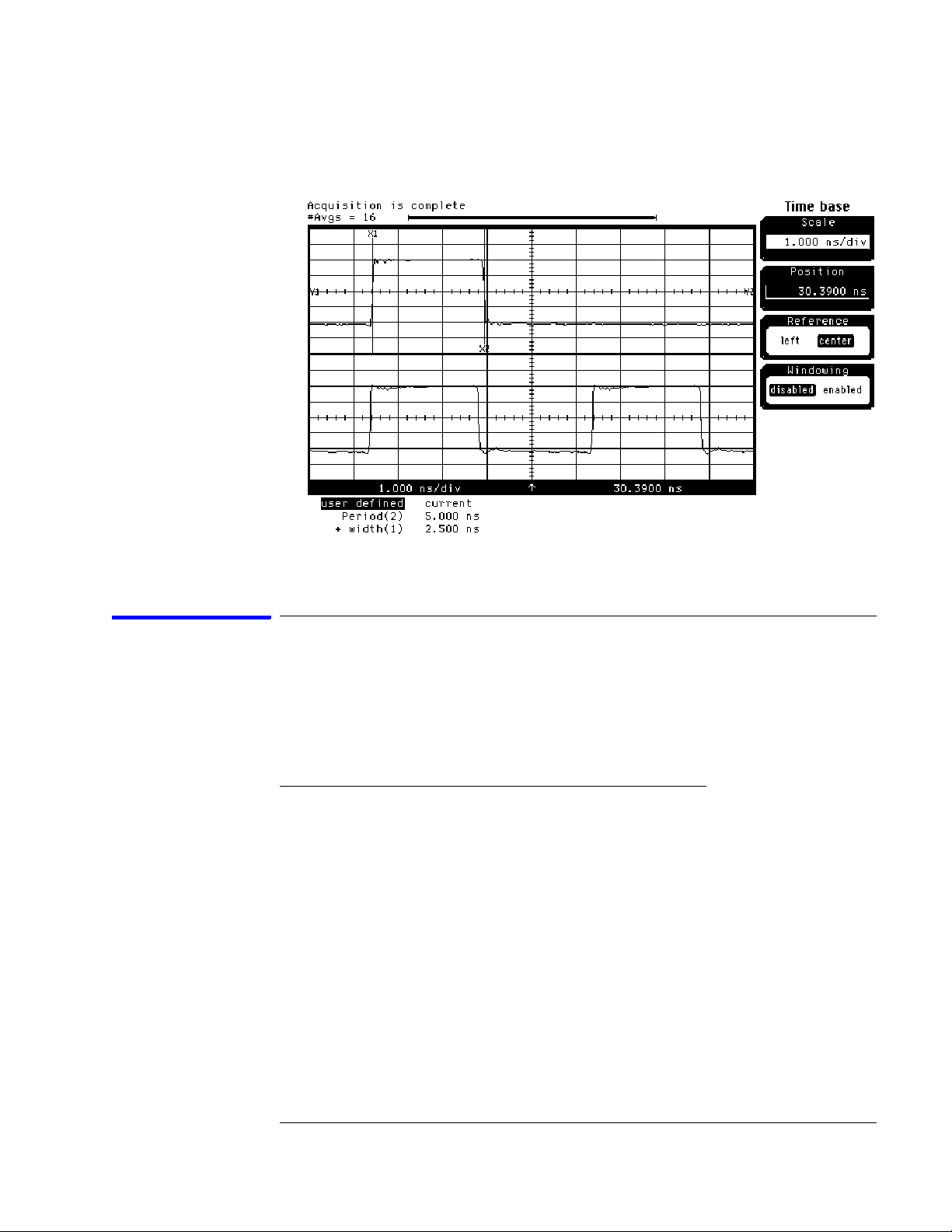
Verify the test signal
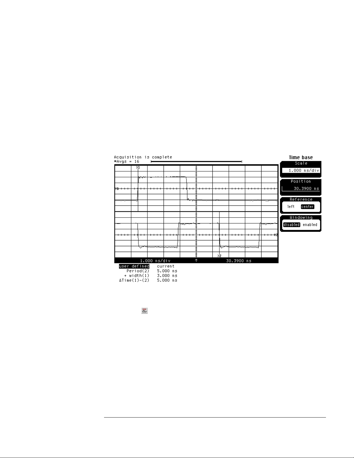
1 Check the clock period. Using the oscilloscope, verify that the master-to-
master clock time is 5.000 ns, +0 ps or −100 ps:
a In the oscilloscope Timebase menu, select Scale: 1.000 ns/div.
b In the oscilloscope Timebase menu, select Position. Using the
oscilloscope knob, position the clock waveform so that a rising edge
appears at the left of the display.
c On the oscilloscope, select [Shift] Period: channel 2, then select [Enter]
to display the clock period (Period(2)). If the period is not less than
5.000 ns, go to step d. If the period is less than 5.000 ns, go to step 2.
d In the oscilloscope Timebase menu, increase Position 5.000 ns. If the
period is not less than 5.000 ns, decrease the pulse generator Period in
until one of the two periods measured is less than 5.000 ns.
2 Check the data pulse width. Using the oscilloscope, verify that the data
pulse width is 2.500 ns, +0 ps or −100 ps.
a In the oscilloscope Timebase menu, select Position. Using the
oscilloscope knob, position the data waveform so that the waveform is
centered on the screen.
b On the oscilloscope, select [Shift] + width: channel 1, then select
[Enter] to display the data signal pulse width (+ width(1)).
40
Page 41
Chapter 3: Testing Performance
To test the single-clock, single-edge, state acquisition
c If the pulse width is outside the limits, adjust the pulse generator
channel 2 width until the pulse width is within limits.
Check the setup/hold combination
The following setup/hold combinations will be tested:
Setup/Hold Combinations
Te s t
Combination
1 4.50/-2.0 ns 2.5 ns -3.25 ns
2 -2.0/4.50 ns 2.5 ns +3.25 ns
1 Disable the pulse generator channel 1 COMP (with the LED off).
2 Using the Delay mode of the pulse generator channel 1, position the pulses
according to the setup time of the setup/hold combination selected,
+0.0 ps or −100 ps as measured on the oscilloscope:
a On the Oscilloscope, select [Define meas] Define ∆ Time - Stop edge:
rising, Edge number 2.
b In the oscilloscope timebase menu, select Position. Using the
oscilloscope knob, position the data waveform so the falling edge is near
the center of the display.
Setup/Hold
Times
Setup/Hold
Window
Sample Position
(in middle of Window)
41
Page 42

Chapter 3: Testing Performance
To test the single-clock, single-edge, state acquisition
c On the oscilloscope, select [Shift] ∆ Time, then select [Enter] to display
the setup time (∆ Time(1)-(2)).
d Adjust the pulse generator channel 1 Delay until the pulses are aligned
according to the setup time of the setup/hold combination selected,
+0.0 ps or –100 ps.
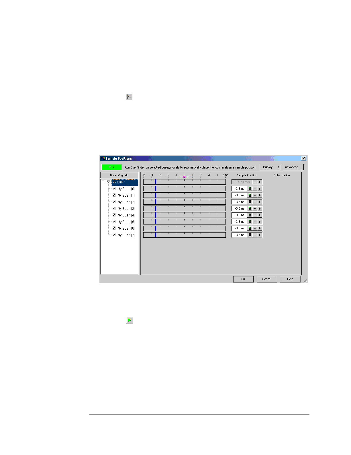
3 Select the logic analyzer sample positions:
a Click the Sampling Setup icon. The Analyzer Setup dialog opens with
the Sampling tab displayed.
b Click Sample Positions....
c In the Sample Positions dialog, drag the blue bar for My Bus 1 to the
sample position of the first setup/hold combination to be tested (or
enter the value in the signal fields).
42
Page 43

Chapter 3: Testing Performance
To test the single-clock, single-edge, state acquisition
d Click OK to close the Sample Positions dialog.
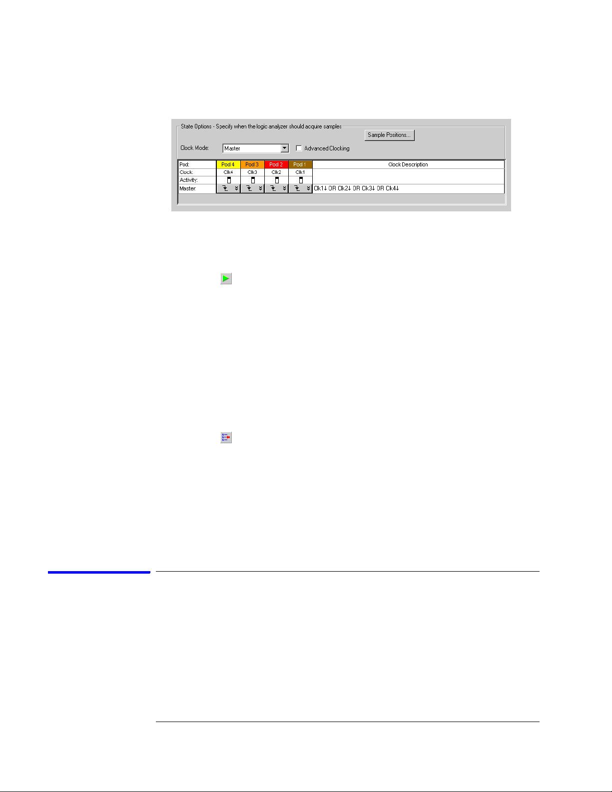
4 Select the clock to be tested:
The following clock configurations will be used in steps 4, 5, and 6.
a In the Analyzer Setup dialog, click on the Sampling tab.
b In the Sampling tab, click the Master button for the first clock to be
tested (Clk 1) and select Rising Edge.
43
Page 44

Chapter 3: Testing Performance
To test the single-clock, single-edge, state acquisition
c Click the Master buttons for the remaining clocks and select Don't Care
to turn off the other clocks.
d Connect the clock to be tested to the pulse generator channel 1 output.
e Click OK to close the Analyzer Setup dialog.
5 Verify the test data:
a Click the Run icon.
b If you have not already done so, do “Set up the Markers:” on page 34.
c If the "can't find 4096 occurence(s)" message does not appear, the test
passes.
The test passes when the logic analyzer finds all occurances of the patterns
programmed into the Markers. If the test passes, record a "Pass" in the
performance test record under single-clock single-edge next to the clock and
edge being tested.
6 Test the next clock:
a Click on the Sampling Setup icon.
b Disconnect the clock just tested from the pulse generator.
c Repeat steps 4, 5, and 6 for the next clock configuration listed in step 4
until all listed clock combinations have been tested.
7 Enable the pulse generator channel 1 COMP (with the LED on).
8 Using the Delay mode of the pulse generator channel 1, position the pulses
according to the setup/hold combination selected, +0.0 ps or –100 ps as
measured on the oscilloscope:
a On the Oscilloscope, select [Define meas] Define ∆ Time - Stop edge:
falling.
b On the oscilloscope, select [Shift] ∆ Time. Select Start src: channel 1,
44
Page 45

Chapter 3: Testing Performance
To test the single-clock, single-edge, state acquisition
then select [Enter] to display the setup time (∆ Time(1)-(2)).
c Adjust the pulse generator channel 1 Delay until the pulses are aligned
according to the setup time of the setup/hold combination selected,
+0.0 ps or –100 ps.
9 Select the clock to be tested:
The following clock configurations will be used in steps 9, 10 and 11.
a In the Analyzer Setup dialog, click the Sampling tab.
b In the Sampling tab, click the Master button for the first clock to be
tested (Clk 1) and select Falling Edge.
45
Page 46

Chapter 3: Testing Performance
To test the single-clock, single-edge, state acquisition
c Click the Master buttons for the remaining clocks and select Don't Care
to turn off the other clocks.
d Connect the clock to be tested to the pulse generator channel 1 output.
e Click OK to close the Analyzer Setup dialog.
10 Verify the test data:
a Click the Run icon.
b If you have not already done so, do “Set up the Markers:” on page 34.
c If the "can't find 4096 occurence(s)" message does not appear, the test
passes.
The test passes when the logic analyzer finds all occurances of the patterns
programmed into the Markers. If the test passes, record a "Pass" in the
performance test record under single-clock single-edge next to the clock and
edge being tested.
11 Test the next clock:
a Click the Sampling Setup icon.
b Disconnect the clock just tested from the pulse generator.
c Repeat steps 9, 10, and 11 for the next clock configuration listed in step
9 until all listed clock combinations have been tested.
12 Test the next setup/hold combination:
a Click the Bus/Signal Setup icon.
b Disconnect the clock just tested from the pulse generator.
c Repeat steps 1 through 12 for the next setup/hold combination listed on
page 41.
46
Page 47

Chapter 3: Testing Performance
To test the single-clock, single-edge, state acquisition
Test the next channels (1680/81A,AD and 1690/91A,AD)
Connect the next combination of data channels and clock channels; then, test
them.
Start with “Connect and configure the logic analyzer” on page 37, connect the
next combination; then, continue through the complete test.
47
Page 48

Chapter 3: Testing Performance
To test the multiple-clock state acquisition
To test the multiple-clock state acquisition
Testing the multiple-clock, state acquisition verifies the performance of the
following specifications:
• Minimum master-to-master clock time.
• Maximum state acquisition speed.
• Setup/Hold time for multiple-clock, state acquisition.
This test checks two combinations of data using multiple clocks at two selected
setup/hold times.
Equipment Required
Equipment Critical Specifications Recommended Model/Part
Pulse Generator 200 MHz 3.0 ns pulse width,
< 600 ps rise time
Digitizing Oscilloscope ≥ 6 GHz bandwidth, < 58 ps rise time 54750A w/ 54751A
Adapter SMA(m)-BNC(f) 1250-1200
SMA Coax Cable (Qty 3) 18 GHz bandwidth 8120-4948
Coupler BNC(m)(m) 1250-0216
BNC Test Connector,
6x2 (Qty 4)
8133A option 003
Set up the equipment
1 If you have not already done so, do the following procedures:
“To set up the test equipment and the logic analyzer” on page 23.
“To set up the logic analyzer for the state mode tests” on page 33.
2 Increase the pulse generator channel 2 width to 3.000 ns.
48
Page 49
Chapter 3: Testing Performance
To test the multiple-clock state acquisition
Connect and configure the logic analyzer
1 Using the 6-by-2 test connectors, connect the first combination of logic
analyzer clock and data channels listed in one of the following tables to the
pulse generator.
If you are testing a 1680/81/90/91A,AD, you will repeat this test for the second
combination.
2 Using SMA cables, connect channel 1, channel 2, and trigger of the
oscilloscope to the pulse generator.
Connect the 1680/81/90/91A,AD Logic Analyzer to the Pulse Generator
Tes ti ng
Combinations
1 Pod 1, channel 3
2 Pod 1, channel 11
*1680A, AD or 1690A, AD only.
Connect to 8133A
Channel 2 Output
Pod 3, channel 3
Pod 5, channel 3
Pod 7, channel 3
Pod 3, channel 11
Pod 5, channel 11
Pod 7, channel 11
Connect to 8133A
Channel 2 Output
Pod 2, channel 3
Pod 4, channel 3
Pod 6, channel 3
Pod 8, channel 3 *
Pod 2, channel 11
Pod 4, channel 11
Pod 6, channel 11
Pod 8, channel 11 *
Connect to 8133A
Channel 1 Output
Clock/data channel for
Pod 1, 2, 3, and 4
(Clk 1, Clk 2, Clk 3,
Clk 4)
Clock/data channel for
Pod 1, 2, 3, and 4
(Clk 1, Clk 2, Clk 3,
Clk 4)
49
Page 50
Chapter 3: Testing Performance
To test the multiple-clock state acquisition
Connect the 1682/83/92/93A,AD Logic Analyzer to the Pulse Generator
Tes ti ng
Combination
1 Pod 1, channel 3
*1682A, AD or 1692A, AD only.
Connect to 8133A
Channel 2 Output
Pod 2, channel 3
Pod 3, channel 3
Pod 4, channel 3
Connect to 8133A
Channel 2 Output
Pod 1, channel 11
Pod 2, channel 11
Pod 3, channel 11 *
Pod 4, channel 11 *
Connect to 8133A
Channel 1 Output
Clock/data channel for Pod 1,
2, 3, and 4 (Clk 1, Clk 2, Clk 3,
Clk 4)
3 Activate the data channels that are connected according to one of the
previous tables:
a Click the Bus/Signal Setup icon. The Analyzer Setup dialog opens.
b Under the Buses/Signals tab, click Delete All at the bottom of the
dialog.
c Using the mouse, activate the data channels being tested. Assign
channels to bus/signal name My Bus 1.
d Click OK to close the Analyzer Setup dialog.
50
Page 51

Chapter 3: Testing Performance
To test the multiple-clock state acquisition
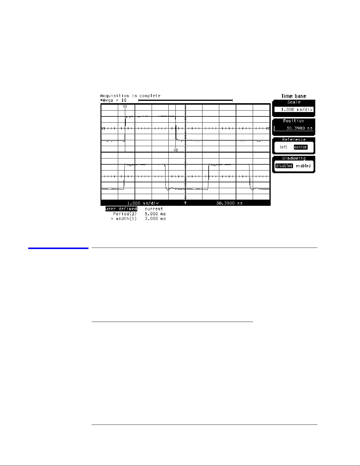
Verify the test signal
1 Check the clock period. Using the oscilloscope, verify that the master-to-
master clock time is 5.000 ns, +0 ps or –100 ps:
a In the oscilloscope Timebase menu, select Scale: 1.000 ns/div.
b In the oscilloscope Timebase menu, select Position. Using the
oscilloscope knob, position the clock waveform so that a rising edge
appears at the left of the display.
c On the oscilloscope, select [Shift] Period: channel 2, then select [Enter]
to display the clock period (Period(2)). If the period is not less than
5.000 ns, go to step d. If the period is less than 5.000 ns, go to step 2.
d In the oscilloscope Timebase menu, increase Position 5.000 ns. If the
period is not less than 5.000 ns, decrease the pulse generator Period in
10 ps increments until one of the two periods measured is less than
5.000 ns.
2 Check the data pulse width. Using the oscilloscope verify that the data
pulse width is 3.000 ns, +0 ps or −100 ps:
a In the oscilloscope Timebase menu, select Position. Using the
oscilloscope knob, position the data waveform so that the waveform is
centered on the screen.
51
Page 52
Chapter 3: Testing Performance
To test the multiple-clock state acquisition
b On the oscilloscope, select [Shift] + width: channel 1, then select
[Enter] to display the data signal pulse width (+ width (1)).
c If the pulse width is outside the limits, adjust the pulse generator
channel 2 width until the pulse width is within limits.
Check the setup/hold with single clock edges, multiple clocks
The following setup/hold combinations will be tested.
Setup/Hold Combinations
Te s t
Combination
1 5.0/-2.0 ns 3.0 ns -3.5 ns
2 -1.5/4.50 ns 3.0 ns +3.0 ns
1 Disable the pulse generator channel 1 COMP (LED off).
2 Using the Delay mode of the pulse generator channel 1, position the pulses
according to the setup time of the setup/hold combination selected,
+0.0 ps or −100 ps as measured on the oscilloscope:
a On the Oscilloscope, select [Define meas] Define ∆ Time - Stop edge:
rising, Edge number 2.
Setup/Hold
Times
Setup/Hold
Window
Sample Position
(in middle of Window)
52
Page 53

Chapter 3: Testing Performance
To test the multiple-clock state acquisition
b In the oscilloscope timebase menu, select Position. Using the
oscilloscope knob, position the data waveform so the falling edge is near
the center of the display.
c On the oscilloscope, select [Shift] ∆ Time, then select [Enter] to display
the setup time (∆ Time(1)-(2)).
d Adjust the pulse generator channel 1 Delay until the pulses are aligned
according to the setup time of the setup/hold combination selected,
+0.0 ps or –100 ps.
3 Select the clocks to be tested:
a Click the Sampling Setup icon. The Analyzer Setup dialog opens.
b In the Sampling tab, click the Master button for one of the clocks and
select Rising Edge.
c Repeat the above steps for each of the remaining clocks until all clocks
have been configured with Rising Edge.
53
Page 54
Chapter 3: Testing Performance
To test the multiple-clock state acquisition
d Connect all clock channels to the pulse generator channel 1 output.
e Click OK to close the Analyzer Setup dialog.
4 Select the logic analyzer sample positions:
a Click the Sampling Setup icon. The Analyzer Setup dialog opens with
the Sampling tab displayed.
b Click Sample Positions....
c In the Sample Positions dialog, drag the blue bar for My Bus 1 to the
sample position of the first setup/hold combination to be tested (or
enter the value in the signal fields).
d Click OK to close the Sample Positions dialog.
5 Verify the test data:
a Click the Run icon.
b If you have not already done so, do “Set up the Markers:” on page 34.
c If the "can't find 4096 occurence(s)" message does not appear, then the
test passes.
The test passes when the logic analyzer finds all occurances of the patterns
programmed into the Markers. If the test passes, record a "Pass" in the
performance test record under single-clock single-edge next to the clock and
edge being tested.
54
Page 55
Chapter 3: Testing Performance
To test the multiple-clock state acquisition
6 Enable the pulse generator channel 1 COMP (with the LED on).
7 Using the Delay mode of the pulse generator channel 1, position the pulses
according to the setup/hold combination selected, +0.0 ps or –100 ps:
a On the Oscilloscope, select [Define meas] Define ∆ Time - Stop edge:
falling.
b On the oscilloscope, select [Shift] ∆ Time. Select Start src: channel 1,
then select [Enter] to display the setup time (∆ Time(1)-(2)).
c Adjust the pulse generator channel 1 Delay until the pulses are aligned
according to the setup time of the setup/hold combination selected,
+0.0 ps or –100 ps.
8 Select the clocks to be tested:
a Click the Sampling Setup icon. The Analyzer Setup dialog opens.
b In the Sampling tab, click the Master button for one of the clocks and
select Falling Edge.
c Repeat the above steps for each of the remaining clocks until all clocks
55
Page 56
Chapter 3: Testing Performance
To test the multiple-clock state acquisition
have been configured with Falling Edge.
d Click OK to close the Analyzer Setup dialog.
9 Verify the test data:
a Click the Run icon.
b If you have not already done so, do “Set up the Markers:” on page 34.
c If the "can't find 4096 occurence(s)" message does not appear, the test
passes.
The test passes when the logic analyzer finds all occurances of the patterns
programmed into the Markers. If the test passes, record a "Pass" in the
performance test record under single-clock single-edge next to the clock and
edge being tested.
10 Test the next setup/hold combination:
a Click the Bus/Signal Setup icon.
b Disconnect the clock just tested from the pulse generator.
c Repeat steps 1 through 10 for the next setup/hold combination listed in
step 1 in page 52.
When aligning the data and clock waveforms using the oscilloscope, align the
waveforms according to the setup time of the setup/hold combination being
tested, +0.0 ps or −100 ps.
Test the next channels (1680/81A, AD and 1690/91A, AD)
Connect the next combination of data channels and clock channels, then repeat
the previous test.
Start with “Connect and configure the logic analyzer” on page 49, connect the
next combination, then continue through the complete test.
56
Page 57

Chapter 3: Testing Performance
To test the single-clock, multiple-edge, state acquisition
To test the single-clock, multiple-edge, state acquisition
Testing the single-clock, multiple-edge, state acquisition verifies the performance
of the following specifications:
• Minimum master-to-master clock time.
• Maximum state acquisition speed.
• Setup/Hold time for single-clock, multiple-edge, state acquisition.
This test checks two combinations of data using a multiple-edge single clock at
two selected setup/hold times.
Equipment Required
Equipment Critical Specifications Recommended Model/Part
Pulse Generator 200 MHz 3.0 ns pulse width, < 600 ps rise time 8133A option 003
Digitizing Oscilloscope ≥ 6 GHz bandwidth, < 58 ps rise time 54750A w/ 54751A
Adapter SMA(m)-BNC(f) 1250-1200
SMA Coax Cable (Qty 3) 18 GHz bandwidth 8120-4948
Coupler BNC(m)(m) 1250-0216
BNC Test Connector,
6x2 (Qty 4)
Set up the equipment
1 If you have not already done so, do the following procedures:
“To set up the test equipment and the logic analyzer” on page 23
“To set up the logic analyzer for the state mode tests” on page 33
2 Modify the following pulse generator settings:
Period: 10.000 ns
Channel 2: Width 3.000 ns
Channel 2: Pulse ÷1
Channel 1: Pulse
Channel 1: Width 5.000 ns
57
Page 58

Chapter 3: Testing Performance
To test the single-clock, multiple-edge, state acquisition
Connect and configure the logic analyzer
1 Using the 6-by-2 test connectors, connect the first combination of logic
analyzer clock and data channels listed in one of the following tables to the
pulse generator.
If you are testing a 1680/81/90/91A,AD, you will repeat this test for the second
combination.
2 Using the SMA cables, connect channel 1, channel 2, and trigger from the
oscilloscope to the pulse generator.
Connect the 1680/81/90/91A,AD Logic Analyzer to the Pulse Generator
Tes ti ng
Combinations
1 Pod 1, channel 3
2 Pod 1, channel 11
*1680A,AD or 1690A,AD only.
Connect to 8133A
Channel 2 Output
Pod 3, channel 3
Pod 5, channel 3
Pod 7, channel 3
Pod 3, channel 11
Pod 5, channel 11
Pod 7, channel 11
Connect to 8133A Channel
2 Output
Pod 2, channel 3
Pod 4, channel 3
Pod 6, channel 3
Pod 8, channel 3 *
Pod 2, channel 11
Pod 4, channel 11
Pod 6, channel 11
Pod 8, channel 11 *
Connect to 8133A
Channel 1 Output
Pod 1 clock/data channel
(Clk1)
Pod 1 clock/data channel
(Clk1)
58
Page 59

Chapter 3: Testing Performance
To test the single-clock, multiple-edge, state acquisition
Connect the 1682/83/92/93A,AD Logic Analyzer to the Pulse Generator
Tes ti ng
Combination
1 Pod 1, channel 3
*1682A,AD or 1692A,AD only.
Connect to 8133A
Channel 2 Output
Pod 2, channel 3
Pod 3, channel 3
Pod 4, channel 3
Connect to 8133A Channel
2 Output
Pod 1, channel 3
Pod 2, channel 3
Pod 3, channel 3 *
Pod 4, channel 3 *
Connect to 8133A
Channel 1 Output
Pod 1 clock/data channel
(Clk1)
3 Activate the data channels that are connected according to one of the
previous tables:
a Click the Bus/Signal Setup icon. The Analyzer Setup dialog opens.
b In the Buses/Signals tab, click Delete All at the bottom of the dialog.
c Using the mouse, activate the data channels being tested. Assign
channels to bus/signal name My Bus 1.
d Click OK to close the Analyzer Setup dialog.
59
Page 60

Chapter 3: Testing Performance
To test the single-clock, multiple-edge, state acquisition
Verify the test signal
1 Check the clock period. Using the oscilloscope, verify that the master-to-
master clock time is 5.000 ns, +0 ps or –100 ps:
a Enable the pulse generator channel 1, channel 2, and trigger outputs
(LED off).
b In the oscilloscope Timebase menu, select Scale: 2.000 ns/div.
c In the oscilloscope Timebase menu, select Position. Using the
oscilloscope knob, position the clock waveform so that a rising edge
appears at the left of the display.
d On the oscilloscope, select [Shift] + width: channel 2, then select
[Enter] to display the master-to-master clock time (+ width(2)). If the
positive-going pulse width is more than 5.000 ns, go to step e. If the
positive-going pulse width is less than or equal to 5.000 ns but greater
than 4.900 ns, go to step 2.
e On the oscilloscope, select [Shift] - width: channel 2, then select [Enter]
(- width(2)). If the negative pulse width is less than or equal to 5.000 ns
but greater than 4.900 ns, go to step 2.
f Adjust the pulse generator Period and Channel 1 width until the
oscilloscope + width (2) or - width (2) reads less than or equal to
5.000 ns, but greater than 4.900 ns.
60
Page 61

Chapter 3: Testing Performance
To test the single-clock, multiple-edge, state acquisition
2 Check the data pulse width. Using the oscilloscope, verify that the data
pulse width is 3.000 ns, +0 ps or −100 ps:
a In the oscilloscope Timebase menu, select Scale: 1.000 ns/div.
b In the oscilloscope Timebase menu, select Position. Using the
oscilloscope knob, position the data waveform so that the waveform is
centered on the screen.
c On the oscilloscope, select [Shift] + width: channel 1, then select
[Enter] to display the data signal pulse width (+ width(1)).
d If the pulse width is outside the limits, adjust the pulse generator
channel 2 width until the pulse width is within limits.
Check the setup/hold with single clock, multiple clock edges
The following setup/hold combinations will be tested.
Setup/Hold Combinations
Te s t
Combination
1 5.0/-2.0 ns 3.0 ns -3.5 ns
2 -1.5/4.50 ns 3.0 ns +3.0 ns
61
Setup/Hold
Times
Setup/Hold
Window
Sample Position
(in middle of Window)
Page 62

Chapter 3: Testing Performance
To test the single-clock, multiple-edge, state acquisition
1 Using the Delay mode of the pulse generator channel 2, position the pulses
according to the setup time of the setup/hold combination selected,
+0.0 ps or –100 ps:
a On the Oscilloscope, select [Define meas] Define ∆ Time - Stop edge:
rising.
b In the oscilloscope timebase menu, select Position. Using the
oscilloscope knob, position the falling edge of the data waveform so that
it is near the center of the display.
c On the oscilloscope, select [Shift] ∆ Time. Select Start src: channel 1,
then select [Enter] to display the setup time (∆ Time(1)-(2)).
d Adjust the pulse generator channel 2 Delay until the pulses are aligned
according to the setup time of the setup/hold combination selected,
+0.0 ps or –100 ps.
2 Select the logic analyzer sample positions:
a Click the Sampling Setup icon. The Analyzer Setup dialog opens with
the Sampling tab displayed.
b Click Sample Positions....
c In the Sample Positions dialog, drag the blue bar for My Bus 1 to the
sample position of the first setup/hold combination to be tested (or
enter the value in the signal fields).
62
Page 63

Chapter 3: Testing Performance
To test the single-clock, multiple-edge, state acquisition
d Click OK to close the Sample Positions dialog.
3 Select the clock to be tested:
The following clock configurations will be used in steps 3, 4, and 5.
a In the Analyzer Setup dialog, click the Sampling tab.
b In the Sampling tab, click the Master button for the first clock to be
tested (Clk 1) and select Both Edges.
c Click the Master buttons for the remaining clocks and select Don't Care
63
Page 64
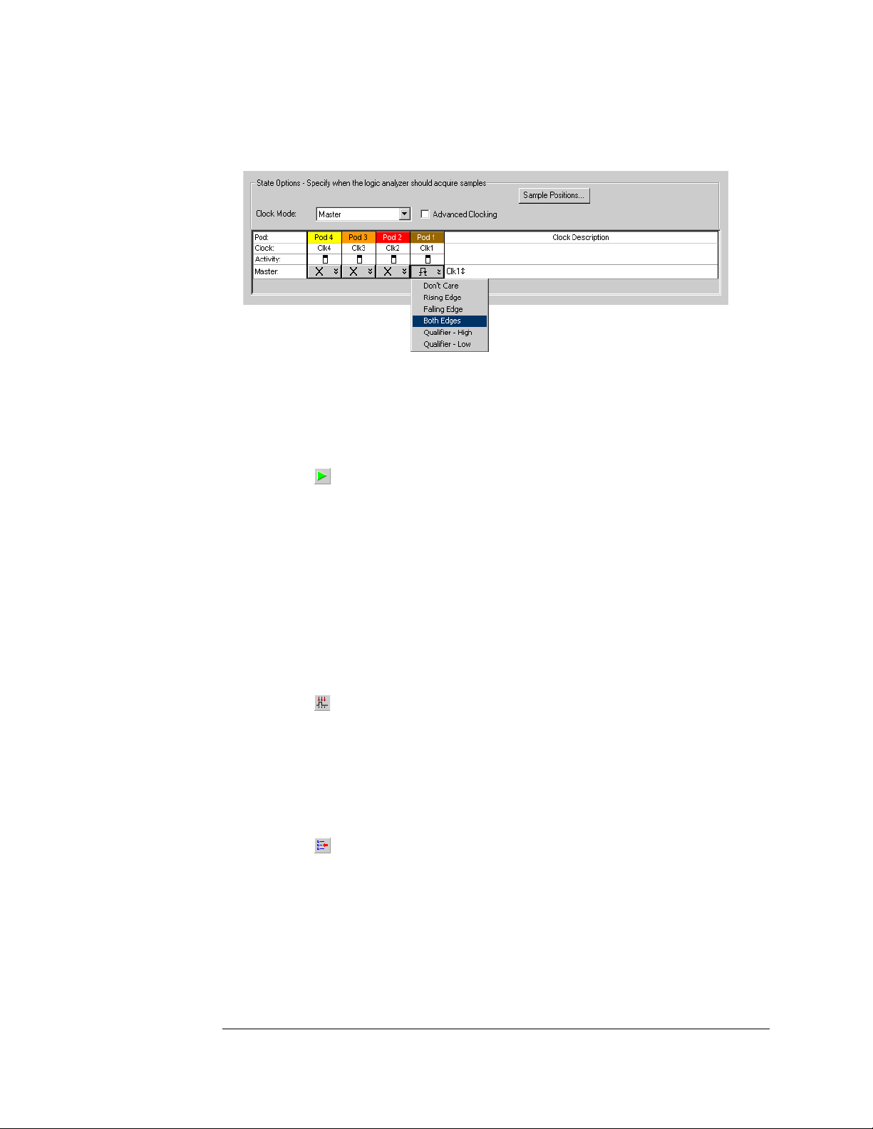
Chapter 3: Testing Performance
To test the single-clock, multiple-edge, state acquisition
to turn off the other clocks.
d Connect the clock to be tested to the pulse generator channel 1 output.
e Click OK to close the Analyzer Setup dialog.
4 Verify the test data:
a Click the Run icon.
b If you have not already done so, do “Set up the Markers:” on page 34.
c If the "can't find 4096 occurence(s)" does not appear, then the test
passes.
The test passes when the logic analyzer finds all occurrences of the patterns
programmed into the Markers. If the test passes, record a "Pass" in the
performance test record under single-clock single-edge next to the clock and
edge being tested.
5 Test the next clock:
a Click the Sampling Setup icon.
b Disconnect the clock just tested from the pulse generator.
c Repeat steps 3, 4, and 5 for the next clock configuration listed in step 4
until all listed clock combinations have been tested.
6 Test the next setup/hold combination:
a Click the Bus/Signal Setup icon.
b Disconnect the clock just tested from the pulse generator.
c Repeat steps 1 through 6 for the next setup/hold combination listed in
step 1 in page 61.
64
Page 65

Chapter 3: Testing Performance
To test the single-clock, multiple-edge, state acquisition
Test the next channels (1680/81A,AD and 1690/91A,AD)
Connect the next combination of data channels and clock channels, then repeat
the previous test.
Start with “Connect and configure the logic analyzer” on page 58, connect the
next combination, then continue through the complete test.
65
Page 66

Chapter 3: Testing Performance
To test the time interval accuracy
To test the time interval accuracy
Testing the time interval accuracy does not check a specification, but does check
the following:
• 125 MHz oscillator
This test verifies that the 125 MHz timing acquisition synchronizing oscillator is
operating within limits.
Equipment Required
Equipment Critical Specifications Recommended Model/Part
Pulse Generator 200 MHz 2.5 ns pulse width, < 600 ps rise time 8133A option 003
Function Generator
SMA Cable 8120-4948
Adapter BNC(m)-SMA(f) 1250-2015
BNC Test Connector, 6x2
Accuracy≤ (5)(10
-6)
x frequency
33250A
Set up the equipment
1 Set up the logic analyzer:
a If you have not already done so, do the procedure “To set up the test
equipment and the logic analyzer” on page 23.
b Exit and restart the Agilent Logic Analyzer applications to reinitialize
the logic analyzer.
2 Set up the pulse generator according to the following table.
Pulse Generator Setup
Timebase Channel 1 Trigger
Mode: Ext Mode: Square Divide: Divide ÷ 1
Delay: 0.000 ns Ampl: 0.50 V
High: -0.90 V Ampl: 0.50 V
Low: -1.70 V Offs: 0.00V
COMP: Disabled (LED off)
66
Page 67
Chapter 3: Testing Performance
To test the time interval accuracy
3 Set up the function generator according to the following table.
Function Generator Setup
Freq: 40.000 MHz
Ampl: 1.00 Vpp
Offset: 0.0 mV
Modulation Off
Connect and configure the logic analyzer
1 Using a 6-by-2 test connector, connect channel 0 of Pod 1 to the pulse
generator channel 1 output.
2 Using the SMA cable and the BNC adapter, connect the External Input of
the pulse generator to the Main Signal of the function generator.
3 Enable the function generator output and the pulse generator Channel 1
output.
4 Configure the Analyzer Setup dialog:
a Click the Sampling Setup icon.
b In the Analyzer Setup dialog, select Timing - Asynchronous Sampling.
c Configure Trigger Position - 100% poststore.
67
Page 68
Chapter 3: Testing Performance
To test the time interval accuracy
d Select an Acquisition Depth of 256K.
5 Configure the logic analyzer channels:
a Click the Buses/Signals tab. In the Buses/Signals tab, click Delete All at
the bottom of the dialog.
b Using the mouse, select Pod 1 channel 0 to activate the channel.
c Click the threshold field for Pod 1. In the Threshold Settings dialog,
select Standard and ECL (–1.30).
d Click OK to close the Threshold Settings dialog.
e Click OK to close the Analyzer Setup dialog.
6 Set up the trigger in the Waveform window:
a Select the Simple Trigger field next to bus/signal name My Bus 1.
68
Page 69
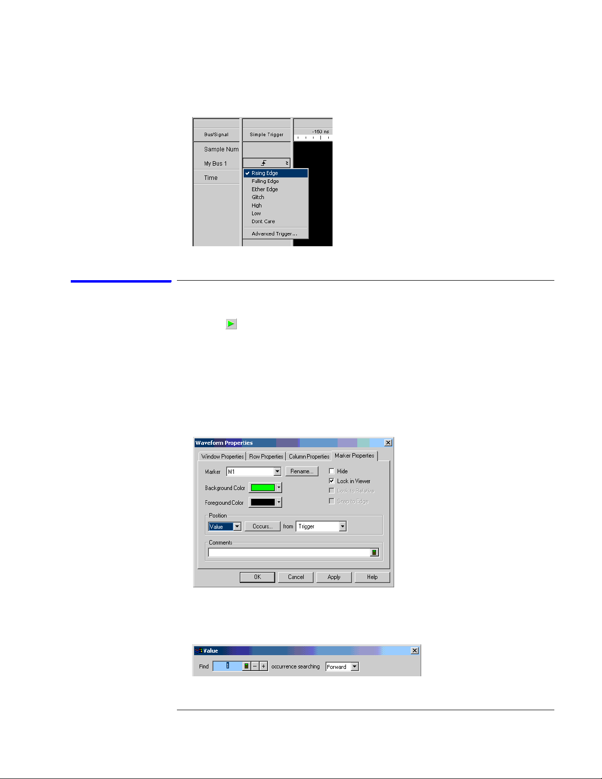
b In the pop-up menu, select Rising Edge.
Acquire and verify the test data
Chapter 3: Testing Performance
To test the time interval accuracy
1 Click the Run icon to fill acquisition memory.
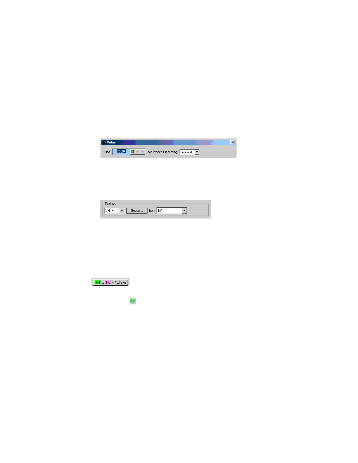
2 Set up the M1 marker for time interval measurement:
a From the main menu, choose Markers>Properties....
b In the Marker Properties tab of the Waveform Properties dialog, select
the M1 marker.
c In the Position box, select Value.
d Click Occurs....
e In the Value dialog, enter “1” in the Find occurrences field.
69
Page 70
Chapter 3: Testing Performance
To test the time interval accuracy
f Click OK to close the Value dialog.
3 Set up the M2 marker for time interval measurement:
a In the Marker Properties tab of the Waveform Properties dialog, select
the M2 marker.
b In the Position box, select Value.
c Click Occurs....
d In the Value dialog, enter “16384” in the Find occurrences field.
e Click OK to close the Value dialog.
f In the Position box, select M1 in the “from” field. The Position should
now read Value Occurs from M1.
g Click Apply; then, click OK to close the Waveform Properties dialog.
4 An Interval Measurement should already be visible in the Markers Toolbar.
If not, choose Markers>New Time Interval Measurement from the main
menu; in the Time Interval dialog, select from M1 to M2, and click OK. An
M1 to M2 time interval field should now be visible in the Markers Toolbar.
5 Click on the Run-Repetitive icon. Allow the logic analyzer to acquire
data for at least 100 runs, as reported at the bottom of the window.
Observe the M1 to M2 time interval field in the Markers Toolbar and
ensure the time interval field is between 40.95571 and 40.96429 µs during
the test.
70
Page 71

Chapter 3: Testing Performance
Performance Test Record
Performance Test Record
Agilent 1680/90-Series Logic Analyzer_______
Serial No.______________________ Work Order No.___________________
Recommended Test Interval - 2 Years/4000 hours Date___________________
Recommended next testing___________________ Temperature___________________
Test Settings Results
Self-Tests
Threshold
Accuracy
Pass/Fail
± (65 mV + 1.5% of threshold setting)
________
Pod 1 ECL, ±84 mV
0 V, ±65 mV
Pod 2 ECL, ±84mV
0 V, ± 65mV
Pod 3 ECL, ±84 mV
0 V, ±65 mV
Pod 4 ECL, ±84 mV
0 V, ±65 mV
Pod 5 ECL, ±84 mV
0 V, ±65 mV
Pod 6 ECL, ±84 mV
0 V, ±65 mV
Pod 7 ECL, ±84 mV
0 V, ±65 mV
Pod 8 ECL, ±84 mV
0 V, ±65 mV
Pass/Fail
Pass/Fail
Pass/Fail
Pass/Fail
Pass/Fail
Pass/Fail
Pass/Fail
Pass/Fail
Pass/Fail
Pass/Fail
Pass/Fail
Pass/Fail
Pass/Fail
Pass/Fail
Pass/Fail
Pass/Fail
________
________
________
________
________
________
________
________
________
________
________
________
________
________
________
________
71
Page 72

Chapter 3: Testing Performance
Performance Test Record
Performance Test Record (continued)
Test Settings Results
Single-Clock, SingleEdge Acquisition
All Pods, Channel 3 Setup/Hold Time 4.5/-2.0 ns Clk 1↑
Clk 2↑
Clk 3↑
Clk 4↑
Setup/Hold Time -2.0/4.5 ns Clk 1↑
Clk 2↑
Clk 3↑
Clk 4↑
All Pods, Channel 11 Setup/Hold Time 4.5/-2.0 ns Clk 1↑
Clk 2↑
Clk 3↑
Clk 4↑
Setup/Hold Time -2.0/4.5 ns Clk 1↑
Clk 2↑
Clk 3↑
Clk 4↑
Multiple-Clock,
Multiple-Edge
Acquisition
Pass/Fail Pass/Fail
________
________
________
________
________
________
________
________
________
________
________
________
________
________
________
________
Clk 1↓
Clk 2↓
Clk 3↓
Clk 4↓
Clk 1↓
Clk 2↓
Clk 3↓
Clk 4↓
Clk 1↓
Clk 2↓
Clk 3↓
Clk 4↓
Clk 1↓
Clk 2↓
Clk 3↓
Clk 4↓
________
________
________
________
________
________
________
________
________
________
________
________
________
________
________
________
All Pods, Channel 3 Setup/Hold Time 5.0/-2.0 ns Clk 1↑ + Clk 2↑ +
Clk 3↑ + Clk 4↑
Setup/Hold Time -1.5/4.5 ns Clk 1↑+ Clk 2↑ +
Clk 3↑ + Clk 4↑
All Pods, Channel 11 Setup/Hold Time 5.0/-2.0 ns Clk 1↑ + Clk 2↑ +
Clk 3↑ + Clk 4↑
Setup/Hold Time -1.5/4.5 ns Clk 1↑ + Clk 2↑ +
Clk 3↑ + Clk 4↑
72
Pass/Fail Pass/Fail
________ Clk 1↓ + Clk 2↓ +
Clk 3↓ + Clk 4↓
________ Clk 1↓ + Clk 2↓ +
Clk 3↓ + Clk 4↓
________ Clk 1↓+ Clk 2↓ +
Clk 3↓ + Clk 4↓
________ Clk 1↓ + Clk 2↓ +
Clk 3↓ + Clk 4↓
________
________
________
________
Page 73

Performance Test Record (continued)
Test Settings Results
Single-Clock,
Multiple-Edge
Acquisition
All Pods, Channel 3 Setup/Hold Time 5.0/-2.0 ns Clk 1 ↑↓
Setup/Hold Time -1.5/4.5 ns Clk 1 ↑↓
All Pods, Channel 11 Setup/Hold Time 5.0/-2.0 ns Clk 1 ↑↓
Setup/Hold Time -1.5/4.5 ns Clk 1 ↑↓
Time Interval
Accuracy
Expected Limits Measured
Disable pulse generator, channel 1 COMP
(LED off)
Clk 2 ↑↓
Clk 3 ↑↓
Clk 4 ↑↓
Clk 2 ↑↓
Clk 3 ↑↓
Clk 4 ↑↓
Clk 2 ↑↓
Clk 3 ↑↓
Clk 4 ↑↓
Clk 2 ↑↓
Clk 3 ↑↓
Clk 4 ↑↓
Chapter 3: Testing Performance
Performance Test Record
Pass/Fail
_______
_______
_______
_______
_______
_______
_______
_______
_______
_______
_______
_______
_______
_______
_______
_______
40.96 µs 40.95571 µs to
40.96429 µs
73
_________
Page 74

Chapter 3: Testing Performance
Performance Test Record
74
Page 75

4
Calibrating and Adjusting
This chapter gives you instructions for calibrating and adjusting the logic
analyzer.
75
Page 76

Chapter 4: Calibrating and Adjusting
Logic analyzer calibration
The logic analyzer circuitry of the Agilent 1680/90-series logic analyzers does not
require an operational accuracy calibration. To test the logic analyzer circuitry
against specifications (full calibration), refer to chapter 3, "Testing Performance."
76
Page 77

5
Troubleshooting
This chapter helps you troubleshoot the logic analyzer to find defective
assemblies.
77
Page 78

Chapter 5: Troubleshooting
The troubleshooting consists of flowcharts, self-test instructions, and tests. This
information is not intended for component-level repair.
If you suspect a problem, start at the top of the first flowchart. During the
troubleshooting instructions, the flowcharts will direct you to perform other
tests.
The service strategy for this instrument is the replacement of defective
assemblies. This instrument can be returned to Agilent Technologies for all
service work, including troubleshooting. Contact your nearest Agilent
Technologies Sales Office for more details.
CAUTION: Electrostatic discharge can damage electronic components. Use grounded wriststraps
and mats when you perform any service to this instrument or to the cards in it.
NOTE: If any peripheral hardware or software programs were installed by the user into an
Agilent 1680A,AD-series logic analyzer, they must be first uninstalled and removed before
doing any troubleshooting. Removing user-installed hardware or software will rule out the
possibility they are causing problems and/or conflicts in the logic analyzer operating
system or application software. Troubleshooting is best done if the instrument is returned
to its hardware and software factory configuration.
To install the fan guard
Installing the fan guard is recommended for any power-on troubleshooting for
either the Agilent 1680A,AD-series or 1690A,AD-series.
NOTE: The fan guard protects repair personnel from potential injury caused by rotating fan
blades.
1 Remove the chassis from the sleeve. Follow the procedure “To remove the
chassis from the sleeve” on page 114 .
2 Install the fan guard onto the chassis.
a Position the chassis so the handle side is up.
b Slide the fan guard onto the chassis over the fans.
On an Agilent 1680A,AD-series, a guide hole in the fan guard will slide over the
standoff post of the bottom left rear foot (adjacent to the acquisition board BNC
connectors).
78
Page 79

c Install the optional screws as shown.
Chapter 5: Troubleshooting
3 After the required power-on troubleshooting and repair is complete,
reverse the above procedure to remove the fan guard and reassemble the
instrument.
To use the flowcharts
Flowcharts are the primary tool used to isolate defective assemblies. The
flowcharts refer to other tests to help isolate the trouble. The circled letters on
the charts indicate connections with the other flowcharts. Start your
troubleshooting at the top of the first flowchart.
79
Page 80
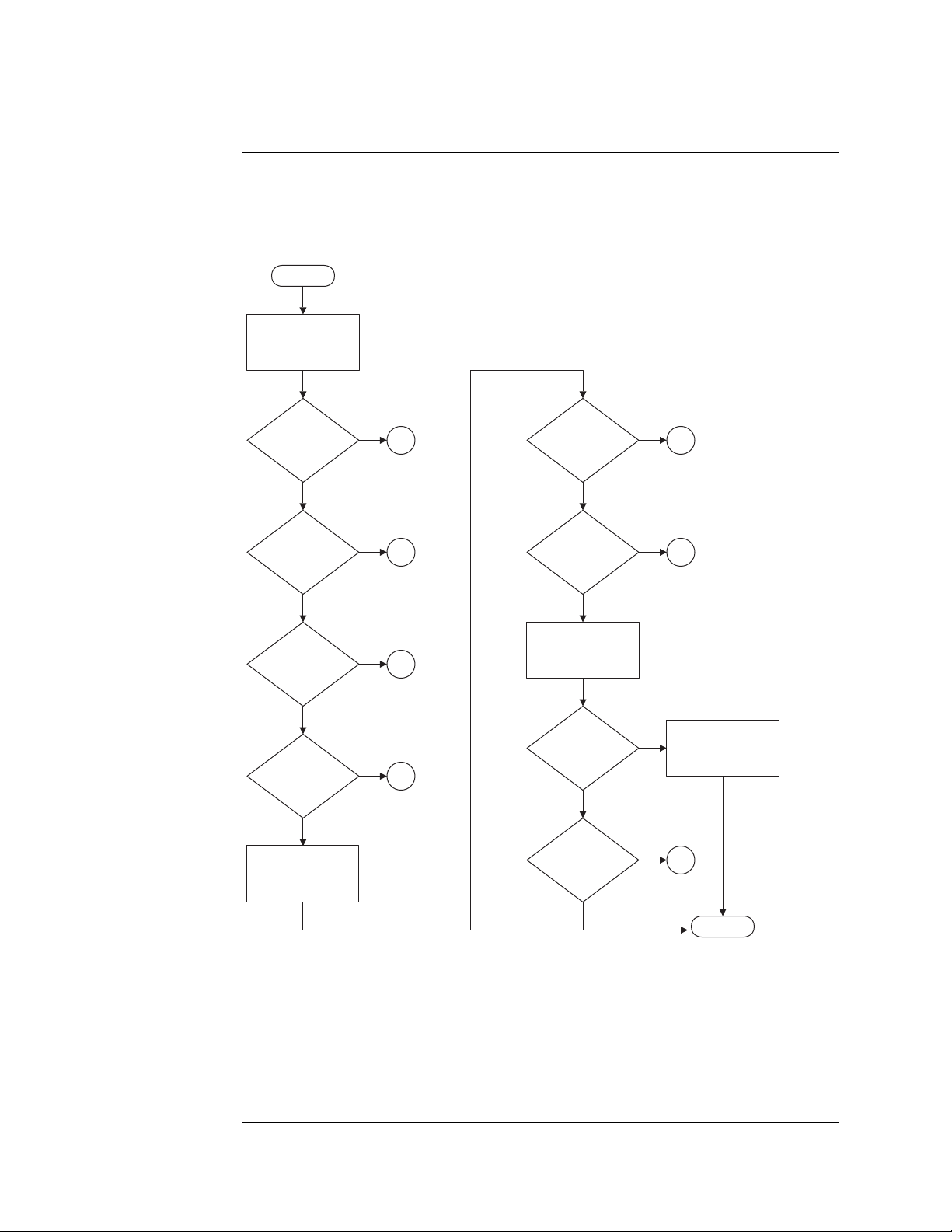
Chapter 5: Troubleshooting
Troubleshooting the Agilent 1680A,AD-series
Troubleshooting the Agilent 1680A,AD-series
START
Apply power. Observe
the instrument
front panel.
Did the front
panel indicators
flash?
Yes
Are all
instrument power
supply fans
running?
Yes
Does the
display light
up?
Yes
Does the
instrument finish
booting?
Yes
Launch the
Agilent Logic Analyzer
application software.
No
No
No
No
Does the
2
3
4
5
application software
launch?
Is the
application
Online?
Do the self test.
Refer to Chapter 5.
Do the self
tests pass?
Is the problem
still present?
Yes
Yes
Yes
No
No
No
No
Yes
6A
6B
Replace the
acquisition
board.
7
DONE
80
Page 81

Chapter 5: Troubleshooting
Troubleshooting the Agilent 1680A,AD-series
2
Are the power
supply fans
running?
Yes
Are the instrument
fans running?
Yes
Remove the cover.
Ensure all front panel
cables are properly
connected.
Are all cables
connected?
No
Reconnect the front
panel cables.
No
No
Yes
Replace the front panel
circuit board.
Ensure the power cord
is properly connected.
Is the power cord
connected?
Yes
Suspect the power
supply. Perform "To
test the power supply
voltages" in Chapter 5.
Do all test points
pass?
Yes
Ensure all instrument
cables are connected
and properly seated.
No
No
Reconnect the
power cord.
Replace the
power supply.
1
81
Page 82
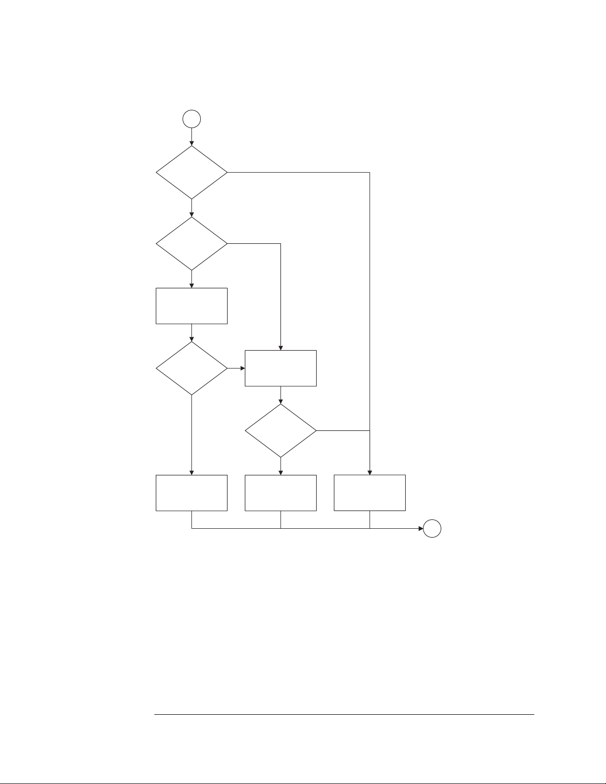
Chapter 5: Troubleshooting
Troubleshooting the Agilent 1680A,AD-series
3
Are the power
supply fans
running?
Yes
Are both instrument
fans stopped?
No
Verify the fan voltage.
Perform "To test the
fan voltage" in Chapter 5.
Are the fan
voltages OK?
Yes
No
Yes
Suspect the power supply.
No
Perform "To test the
power supply voltages"
in Chapter 5.
points pass?
Do all test
No
Yes
Replace the
defective fan.
Replace the
distribution board.
Replace the
power supply.
1
82
Page 83

4
Connect an external
800x600 PC monito to
the instrument.
Chapter 5: Troubleshooting
Troubleshooting the Agilent 1680A,AD-series
Does the external
monitor light up?
Yes
Is the external
monitor readable?
Yes
Possible problem with
LCD display, inverter,
or cables.
No
No
Possible problem with
motherboard or PCI
video board.
Ensure PCI video board
is seated in the
motherboard connector.
Is the PCI video
board seated in the
motherboard?
Yes
Replace PCI video
board with known
good board.
Reconnect an external
800x600 PC monitor to
the instrument.
No
motherboard connector.
Reseat the PCI
video board in the
Are all cables
connected and
seated?
No
Reconnect or reseat
all video cabling.
Yes
Replace the LCD
display and inverter.
Is the external
monitor readable?
Yes
Replace defective
PCI video board.
No
Replace motherboard.
1
83
Page 84
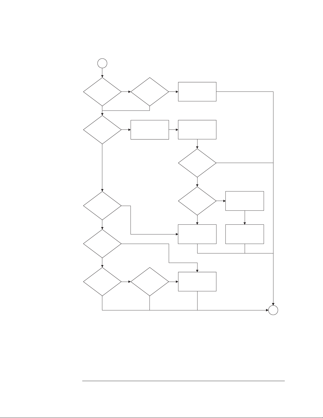
Chapter 5: Troubleshooting
Troubleshooting the Agilent 1680A,AD-series
5
Does the blue
Agilent Logic Analyzer
screen appear?
No Yes
message appear
during POST?
No
* Microsoft Windows XP Technical Resources
will help identify the cause of specific error
messages. The Microsoft Windows XP
http://www.microsoft.com/windowsxp/pro
Does *error
message appear re:
Master Boot
Record?
No
Does
"starting Windows..."
appear?
Yes
YesDoes an *error
Technical Resources are currently at
Yes
No
Does the
instrument boot
any further?
Remove power from
instrument, remove cover,
check that all cables
are properly seated.
No
Replace the CPU
motherboard.
Reapply power,
observe if any error
messages appear.
Does an *error
message appear?
Yes
Does *error
message refer to
hard disk drive?
Yes
Replace the
hard disk drive.
No
No
Address the specific
message as a
hardware failure.
Replace failed
hardware as indicated
in the error message.
Yes
Does operating
system logon screen
appear?
Yes Ye s
Is logon
disabled?
NoNo
Reinstall operating
system. See "To
recover the operating
system".
1
84
Page 85

Chapter 5: Troubleshooting
Troubleshooting the Agilent 1680A,AD-series
6A
Uninstall, then reinstall
the Agilent Logic
Analyzer application.
Does the
application
software launch?
Yes
Do error
messages appear?
No
No
Yes
Perform "To recover
the operating system"
in Chapter 5.
1
6B
Remove power from
instrument, remove
cover, check internal
IEEE 1394 cabling.
Are all cables
connected and
seated?
Yes
Reseat the PCI IEEE
board in ISA slot 1*.
Apply power to the
instrument.
Is the application
Online?
Yes
No
No
Reconnect or reseat
all internal cabling.
* All PCI boards must be installed in
the correct slots. See "To remove
the ISA board" in Chapter 6.
Observe the status LEDs
on the acquisition board.
Refer to Acquisition board
status LEDs.
Are any green
LEDs blinking?
No
Possible problem with PCI
IEEE 1394 board. Replace
the PCI IEEE 1394 board.
Yes
Possible problem with
acquisition board.
Replace acquisition bd.
1
85
Page 86
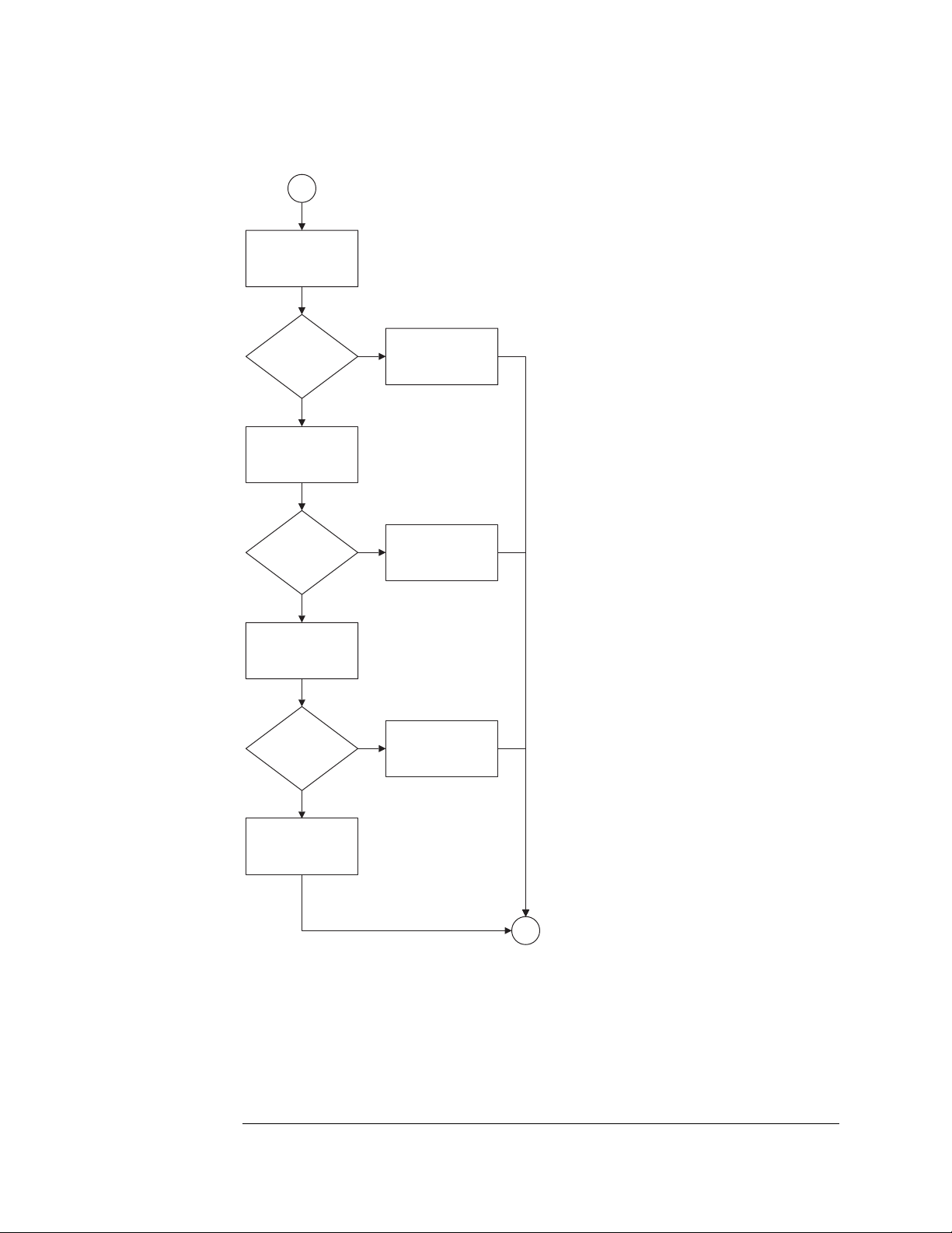
Chapter 5: Troubleshooting
Troubleshooting the Agilent 1680A,AD-series
7
Possible problem with
logic analyzer cables. Do
the cable test in Chapter
5 on suspect pod.
Does cable
test pass?
No
Swap suspect probe
tip assembly with
known good one.
Does cable
test pass?
No
Swap suspect cable
assembly with known
good one.
Does cable
test pass?
Yes
Yes
Yes
The logic analyzer
board if functioning
properly.
Replace defective
probe tip assembly.
Replace
defective cable.
No
Replace logic analyzer
acquisition board.
1
86
Page 87

Chapter 5: Troubleshooting
Troubleshooting the Agilent 1680A,AD-series
To check the power-up tests
The power-up self tests on the 1680A,AD-series logic analyzers is performed by
the Microsoft Windows XP Professional operating system. As part of the Windows
XP Professional power on self test (POST), the presence of all required system
components is verified.
1 Close the Agilent Logic Analyzer application and all other applications
running on the logic analyzer.
2 Shut down the instrument.
a Click on the Start button in the task bar, then select Shut Down.
b In the Shut Down window, select Shut Down from the menu, then
select the OK button.
c After the instrument turns off, press the power button to again apply
power.
Monitor the boot dialogue. When the text "Starting Windows . . ." appears at the
bottom of the screen, this means required system components have been
detected and have passed their power-up self-tests.
To test the power supply voltages
Refer to chapter 6, "Replacing Assemblies," for instructions to remove or replace
covers and assemblies.
This procedure will not expose any problems related to load regulation; however,
it will show most failure modes to over 95% confidence,
WARNING: Hazardous voltages exist on the power supply. This procedure is to be
performed by service-trained personnel aware of the hazards involved, such as
fire and electrical shock.
1 Close the Agilent Logic Analyzer application and all other applications
running on the logic analyzer.
2 Shut down the instrument.
a Click on the Start button in the task bar, then select Shut Down.
b In the Shut Down window, select Shut Down from the menu, then
select the OK button.
87
Page 88

Chapter 5: Troubleshooting
Troubleshooting the Agilent 1680A,AD-series
3 Remove the power supply from the instrument. Refer to “To remove the
power supply” in Chapter 6.
4 After removing the power supply, connect a power cord to the power
supply and plug the power cord into line power.
5 Using DVM, measure the power supply voltages.
Power Supply Voltages
CN1 CN2
Pin Voltage Pin Voltage
1-5 +3.3 V 1-4 -5.2 V
6-7 COM 5 +12 V
8-10 +5 V 6-8 -12 V
11-12 COM 9-12 COM
13-14 +3.3 V 13 +12 V
15-19COM 14-16COM
20-21 +5 V
22-24 COM
6 Note problems with the power supply, then unplug the power supply from
line power. Return to the flow chart.
88
Page 89

Chapter 5: Troubleshooting
Troubleshooting the Agilent 1680A,AD-series
To test the LCD display signals
Before attempting to do this procedure, ensure that the video signal cable
connected to the PCI video board is properly seated. Attempt to reseat the cable
two or three times. If other repairs were done to the instrument, and the video is
now no longer operating, it is very likely that the video cable is not properly
seated.
Refer to chapter 6, "Replacing Assemblies", for instructions to remove or replace
covers and assemblies.
WARNING: Warning Hazardous voltages exist on the power supply and the LCD display,
and the LCD inverter. This procedure is to be performed by service-trained
personnel aware of the hazards involved, such as fire and electric shock.
1 Remove the sleeve. Refer to chapter 6 for more information on how to
remove the sleeve.
2 Connect a power cord to the instrument and apply power.
3 Using an oscilloscope, probe the following pins of J111 for digital signals.
2, 4, 5
9, 10, 11, 13, 14, 15
29, 30, 31, 33, 34, 35, 37
1
41
2
40
01680f01.cdr
89
Page 90

Chapter 5: Troubleshooting
Troubleshooting the Agilent 1680A,AD-series
4 Using an oscilloscope, probe pins 39 and 40 of J111 for +3.3Vdc
If +3.3Vdc is present on J111 of pins 39 and 40, and digital signals are present on
the video data pins indicated above, then the CPU board video circuit is operating
properly.
5 Remove power. Allow time for the capacitors in the power supply to
discharge before disconnecting the power supply, doing the repair, and
reassembling the instrument.
To test disk drive voltages
The following procedure is a guide to help further identify possible problems with
either the flexible disk drive or hard disk drive.
Equipment Required
Equipment Critical Specification Recommended Model/Part
Digitizing Oscilloscope > 100 MHz Bandwidth 54600B
1 Close the Agilent Logic Analyzer application and all other applications
running on the logic analyzer.
2 Shut down the instrument.
a Click on the Start button in the task bar, then select Shut Down.
b In the Shut Down window, select Shut Down from the menu, then
select the OK button.
3 After the instrument turns off, unplug the instrument and remove the
cover.
4 Disconnect the suspect disk drive. Remove the disk drive from the chassis
and reconnect the cable.
5 Troubleshoot a hard disk drive.
a Apply power to the instrument.
90
Page 91

Chapter 5: Troubleshooting
Troubleshooting the Agilent 1680A,AD-series
b As the instrument is booting, probe for digital signals on the hard disk
drive connector according to the following table.
Disk Drive Voltages
Pin No. Signal Voltage Pin No. Signal Voltage Pin No. Signal Voltage
1 RESET 27 IORDY 34 PDIAG
3 - 18 DATA 28 CSEL 35 DA00
20 KEY 29 DMACK 36 DA02
21 DMARQ 31 INTRQ 37 CS0
23 DIOW 32 IOCS16 38 CS1
25 DIOR 33 DA01 39 DASP
Pins 2, 19, 22, 24, 26, 30, 40, are GROUND
Pins 41 and 42 are +5 Vdc
6 Troubleshoot a flexible disk drive.
a Apply power to the instrument.
b After the instrument finished booting, launch the Agilent Logic
Analyzer application.
c Insert a formatted flexible disk in the instrument flexible disk drive.
d Attempt to do a File Save of the Agilent Logic Analyzer default
configuration to the flexible disk drive.
91
Page 92

Chapter 5: Troubleshooting
Troubleshooting the Agilent 1680A,AD-series
e While the instrument is attempting to save the file to flexible disk,
probe for digital signals on the flexible disk drive connector according
to the following table.
Disk Drive Voltages
Pin Signals Pin No. Signal
1+5 V2INDEX
3+5 V4DRIVE SELECT
5 +5 V 6 DISK CHANGE
7 NC 8 READY
9 NC 10 MOTOR ON
11 NC 12 DIRECTION SELECT
13 NC 14 STEP
15 0 V 16 WRITE DATA
17 0 V 18 WRITE GATE
19 0 V 20 TRACK 00
21 O V 22 WR I T E PROT E CT
23 0 V 24 READ DATA
25 0 V 26 SIDE ONE SELECT
7 Repeat steps 1 through 3 above. After the instrument turns off, unplug the
instrument.
8 Replace suspect disk drive if necessary, then reassemble the instrument.
To verify the CD-ROM
The CD-ROM drive itself can be tested using an audio CD. Install CD player-style
headphones in the CD-ROM audio output jack. With the instrument powered on,
insert an audio CD into the CD-ROM drive. If the CD-ROM is operating properly,
it should begin playing the audio CD.
92
Page 93

Chapter 5: Troubleshooting
Troubleshooting the Agilent 1680A,AD-series
To recover the operating system
To reinstall the operating system
Reinstalling the operating system erases the entire hard disk drive and
reinitializes the hard disk drive to its factory configuration. All user data stored
on the hard disk drive will be lost. Reinstalling the operating system is necessary
in case any system level files or other components of the operating system
become corrupted.
The recovery CD-ROM contains an image of the Windows XP Professional
operating system. The CD-ROM contains an install key which recognizes whether
or not the system motherboard is an Agilent logic analyzer motherboard. If the
system motherboard is an Agilent logic analyzer motherboard, then the install key
permits the recovery of the operating system from the CD-ROM to the hard disk
drive.
1 Apply power to the instrument.
2 After applying power, insert the recovery CD-ROM in the instrument CD-
ROM drive.
If the instrument finishes booting, then user files can likely be archived so they
don't become lost.
3 Press the on/off button to turn the instrument off.
4 After a few seconds turn the instrument back on.
5 At the prompt, select "Yes" to reinstall the operating system.
It takes about 1 hour to reinstall the operating system and Agilent Logic Analyzer
application software. At the end of the operating system reinstallation, the logic
analyzer will be in its factory default operating system configuration.
Problems running the Application Software
If there is a problem while running the Agilent Logic Analyzer application
software, then the likely cause would be the application if the error or unusual
behavior appeared while configuring a window or analyzing data.
In the event of a problem of the Agilent Logic Analyzer application software, do
the following steps:
In case the application software becomes unresponsive, do a Ctrl-Alt-Del and follow
the queries to abort the application software. Attempt to restart the application
software and do a measurement.
If there are still problems running the application software, then uninstall and reinstall
93
Page 94

Chapter 5: Troubleshooting
Troubleshooting the Agilent 1680A,AD-series
the application software.
Problems with the Operating System
Operating system applies to the Agilent 1680A,AD-series logic analyzers. The
likely cause would be the operating system if the error or unusual behavior
appeared while doing an operating system task, like printing or configuring the
network.
In the event of a problem with the operating system, do the following steps:
If error messages appear, consult the operating system documentation for information
related to the errors.
In case the whole system becomes unresponsive, turn the instrument off by pressing
the on/off button. If pressing the on/off button does not initiate the power-down
routine, then press and hold the on/off button for 5 seconds until the instrument turns
off.
Turn on the instrument and reattempt the task. If the whole system again becomes
responsive then follow the above procedure To reinstall the operating system.
For a host PC controlling an Agilent 1690A,AD-series hosted logic analyzer,
responsibility of diagnosing errors and problems with utilized system services is
the user's.
94
Page 95

Chapter 5: Troubleshooting
Troubleshooting the Agilent 1690A,AD-series
Troubleshooting the Agilent 1690A,AD-series
START
Apply power.
Are all
instrument and
power supply fans
running?
Yes
Launch the
Agilent Logic Analyzer
application software
on the host PC.
Does the
application software
launch?
Yes
Is the
application
Online?
Yes
Do the self test.
Refer to Chapter 5.
No
No
No
2
3A
3B
Do the self
tests pass?
Yes
Is the problem
still present?
No
No
Yes
Replace the
acquisition
board.
4
DONE
95
Page 96
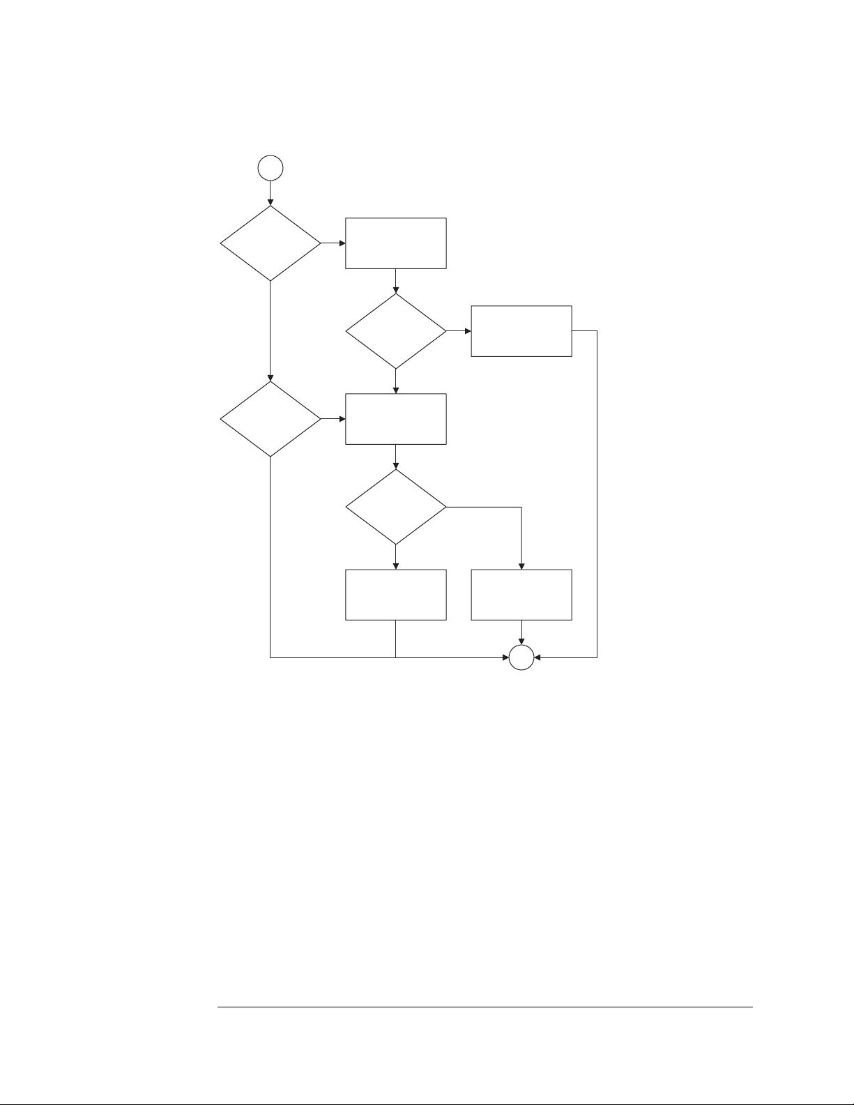
Chapter 5: Troubleshooting
Troubleshooting the Agilent 1690A,AD-series
2
Are the power
supply fans
running?
Yes
Are the instrument
fans running?
Yes
No
Ensure the power cord
is properly connected.
Is the power cord
Suspect the power supply.
No
Perform "To test the
power supply voltages"
in Chapter 5.
points pass?
Ensure all instrument
cables are connected
and properly seated.
connected?
Yes
Do all test
Yes
No
No
Reconnect the
power cord.
Replace the
power supply.
1
96
Page 97

Chapter 5: Troubleshooting
Troubleshooting the Agilent 1690A,AD-series
3A
Uninstall, then reinstall
the Agilent Logic
Analyzer application.
Does the
application
software launch?
Yes
Do error
messages appear?
No
No
Yes
Possible problem with
host operating system.
Consult host PC
documentation.
1
3B
Is the IEEE 1394
cable connected and
seated?
Yes
Perform " To
verify connectivity"
in Chapter 5.
Is connectivity
verified?
Yes
Remove the cover and
observe the status LEDs
on the acquisition board.
No
Uninstall, then reinstall
No
Reconnect or reseat
IEEE 1394 cable.
the Agilent Logic
Analyzer application.
Are any green
LEDs blinking?
No
Possible problem with
PCI IEEE 1394 board on
host PC. Replace
the board.
Yes
Possible problem with
acquisition board.
Replace acquisition bd.
1
97
Page 98

Chapter 5: Troubleshooting
Troubleshooting the Agilent 1690A,AD-series
4
Possible problem with
logic analyzer cables. Do
the cable test in Chapter
5 on suspect pod.
Does cable
test pass?
No
Swap suspect probe
tip assembly with
known good one.
Does cable
test pass?
No
Swap suspect cable
assembly with known
good one.
Does cable
test pass?
Yes
Yes
Yes
The logic analyzer
board if functioning
properly.
Replace defective
probe tip assembly.
Replace
defective cable.
No
Replace logic analyzer
acquisition board.
1
98
Page 99
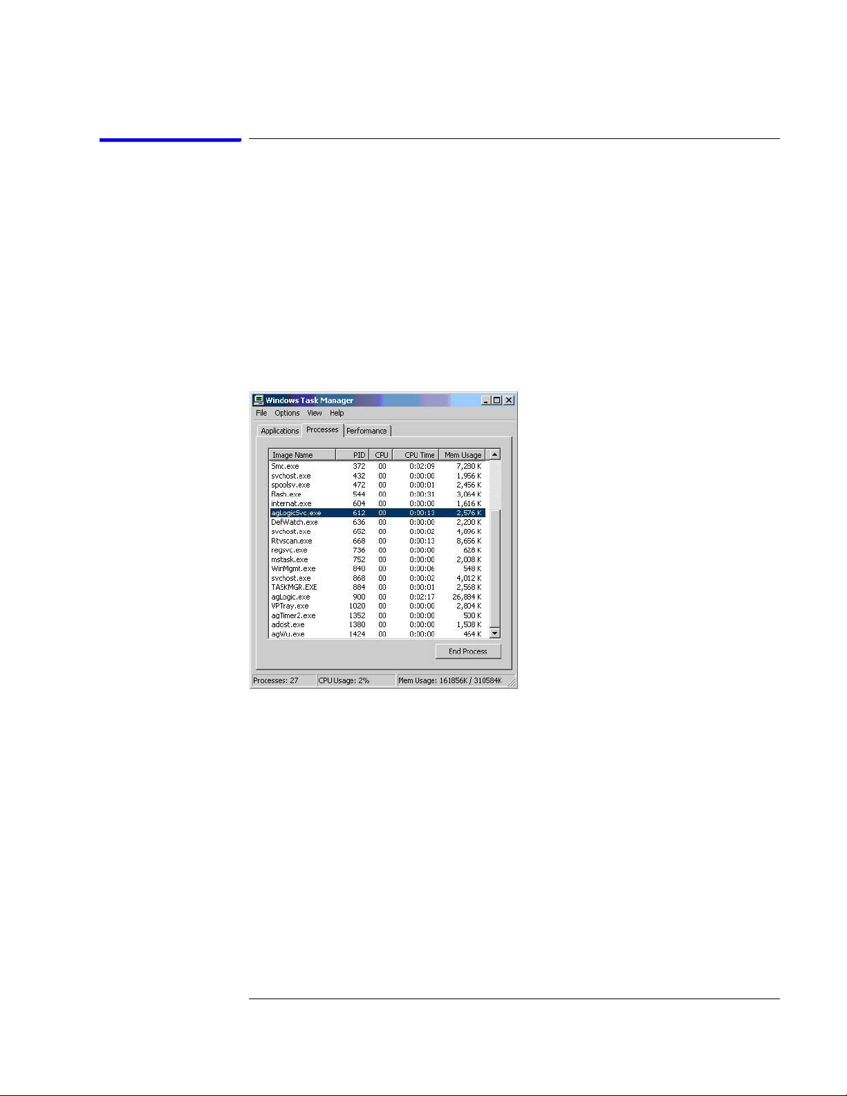
Chapter 5: Troubleshooting
Troubleshooting the Agilent 1690A,AD-series
To verify connectivity
Using Windows Device Manager and Task Manager, you can quickly determine if
the Agilent Logic Analyzer application software is correctly installed on a host
PC.
Task Manager
Use Task Manager to see if the agLogicSvc is running. The agLogicSvc is started
when the PC is booted and establishes connection with the 1690A,AD-series
hosted logic analyzer when the logic analyzer is connected to the PC. If the
agLogicSvc service is not listed, then the host PC will not be able to establish an
interface with the hosted logic analyzer.
If the agLogicSvc service is not listed, then uninstall and reinstall the Agilent
Logic Analyzer application software. If the agLogicSvc service still does not
appear, then there is a problem with your Windows XP Professional operating
system. Consult the documentation for the operating system to further determine
why the service is not being installed and run.
99
Page 100
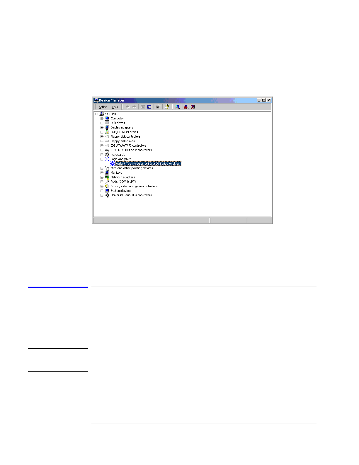
Chapter 5: Troubleshooting
Troubleshooting the Agilent 1690A,AD-series
Device Manager
Use Device Manager to see if the Agilent Logic Analyzer device has been properly
installed. The Device Manager should include an entry "Logic Analyzers" with the
device "Agilent Technologies 1680/1690 Series Analyzer".
If the logic analyzer device is not listed, then uninstall and reinstall the Agilent
Logic Analyzer application software. If the device still does not appear, then there
is a problem with the Windows XP Professional operating system. Consult the
documentation for the operating system to determine why the device is not being
installed and run.
To test the power supply voltages
Refer to chapter 6, "Replacing Assemblies," for instructions to remove or replace
covers and assemblies.
This procedure will not expose any problems related to load regulation; however,
it will show most failure modes to over 95% confidence,
WARNING: Hazardous voltages exist on the power supply. This procedure is to be
performed by service-trained personnel aware of the hazards involved, such as
fire and electrical shock.
1 Close the Agilent Logic Analyzer application and all other applications
running on the logic analyzer.
2 Shut down the instrument.
100
 Loading...