

Page 1

Installation Guide
Publication number 16700-97023
November 2002
For Safety information and Regulatory information, see the pages behind the
index.
© Copyright Agilent Technologies 2000-2002
All Rights Reserved
Agilent Technologies
16700B-Series Logic Analysis
Systems
Page 2
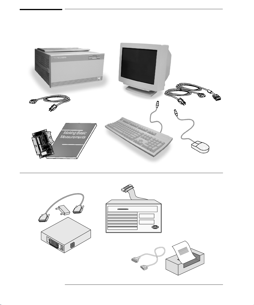
Installation at a Glance
16700B Overview
16700B Mainframe
Power Cable
Training Board & Kit
If ordered:
Monitor
Monitor Cable
Monitor Power Cable
Keyboard
& Mouse
Additional Connections
External Disk Drive & Cable
(Data Drive - Option 008)
(Boot Drive - Option 009)
2
16701A/B
Expander
Frame
Printer &
Cable
Page 3
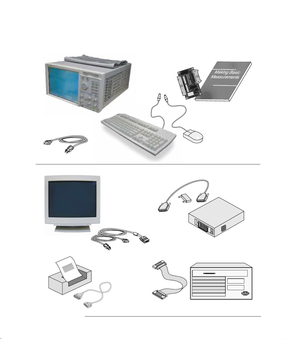
16702B Overview
16702B
Mainframe
Power Cable
Additional Connections
Orderable:
Monitor
Monitor Cable
Monitor Power Cable
Training Board
& Kit
Keyboard
& Mouse
External Disk Drive & Cable
(Data Drive - Option 008)
(Boot Drive - Option 009)
Printer &
Cable
16701A/B Expander Frame
3
Page 4

4
Page 5

Contents
Installation at a Glance
1 General Information 9
To locate information on using the logic analyzer 10
To locate specifications and characteristics 11
To create a backup file of your system settings and license passwords 13
To reload system settings and license passwords 15
2 Connecting and Configuring Hardware 17
To connect the mouse, keyboard, and monitor 18
To configure a monitor for the 16700B 19
To configure an optional monitor for the 16702B 21
To change monitors (16700B or 16702B) 22
To connect to LAN 22
To connect a printer 24
To connect an external data drive (option 008) 26
To disconnect an external data drive (option 008) 30
To connect a removable boot drive (option 009) 31
To disconnect a removable boot drive (option 009) 34
To install software 34
To connect a 16701B expander frame 37
To connect multiple frames 38
To install, remove, or replace measurement modules 42
3 Installing Logic Analyzer
Measurement Modules
45
5
Page 6

Contents
Software Requirements 46
16517/18A Logic Analyzer (2-card module) 47
16517/18A Logic Analyzer (3-card module) 48
16517/18A Logic Analyzer (4-card module) 49
16517/18A Logic Analyzer (5-card module) 50
16557D Logic Analyzer (1-card module) 50
16557D Logic Analyzer (2-card module) 51
16557D Logic Analyzer (3-card module) 52
16557D Logic Analyzer (3-card module) 53
16557D Logic Analyzer (5-card module) 54
16710/11/12A Logic Analyzer (1-card module) 55
16710/11/12A Logic Analyzer (2-card module) 56
16715/16/17A, 16718/19A, 16740/41/42A, 16750/51/52A/B Logic Analyzer (1card module) 57
16715/16/17A, 16718/19A, 16740/41/42A, 16750/51/52A/B Logic Analyzer (2card module) 58
16715/16/17A, 16718/19A, 16740/41/42A, 16750/51/52A/B Logic Analyzer (3card module) 59
16715/16/17A, 16718/19A, 16740/41/42A, 16750/51/52A/B Logic Analyzer (4card module) 60
16715/16/17A, 16718/19A, 16740/41/42A, 16750/51/52A/B Logic Analyzer (5card module) 61
16753/54/55/56A Logic Analyzer (1-card module) 62
16753/54/55/56A Logic Analyzer (2-card module) 63
16753/54/55/56A Logic Analyzer (3-card module) 64
16753/54/55/56A Logic Analyzer (4-card module) 65
16753/54/55/56A Logic Analyzer (5-card module) 66
16760A Logic Analyzer (1-card module) 67
16760A Logic Analyzer (2-card module) 67
16760A Logic Analyzer (3-card module) 68
16760A Logic Analyzer (4-card module) 69
16760A Logic Analyzer (5-card module) 70
4 Installing Oscilloscope
6
Page 7

Contents
Measurement Modules 71
16533/34A Oscilloscope Module (single or multi-card modules) 72
5 Installing Pattern Generator
Measurement Modules
Software Requirements 88
16522A Pattern Generator (1-card module) 88
16522A Pattern Generator (2-card module) 89
16522A Pattern Generator (3-card module) 89
16522A Pattern Generator (4-card module) 90
16522A Pattern Generator (5-card module) 91
16720A Pattern Generator (1-card module) 92
16720A Pattern Generator (2-card module) 92
16720A Pattern Generator (3-card module) 93
16720A Pattern Generator (4-card module) 94
16720A Pattern Generator (5-card module) 95
87
6 Connecting Accessories 97
For More Information
General-purpose probing 99
Isolation adapter (Part number 01650-63203) 101
Direct connection 102
38-pin Low-voltage Probe (E5339A with tip isolation network) 103
38-pin Single-ended Probe (E5346A for analyzers with 40-pin pod
connectors) 104
38-pin Adapter Cable (E5351A no tip network) 105
100-pin Single-ended Probe (E5378A for analyzers with 90-pin pod
connectors) 106
7
Page 8

Contents
100-pin Differential Probe (E5379A for analyzers with 90-pin pod
connectors) 107
38-pin Single-ended Probe (E5380A for analyzers with 90-pin pod
connectors) 108
Half-channel Adapter (E5386A) 109
Single-ended Flying Lead Probe Set (E5382A) 110
Soft Touch Probes (E5387A and E5390A for analyzers with 90-pin pod
connectors) 111
7 Troubleshooting 113
To run self-tests 114
To execute disaster recovery procedures 115
8
Page 9

1
General Information
9
Page 10
Chapter 1: General Information
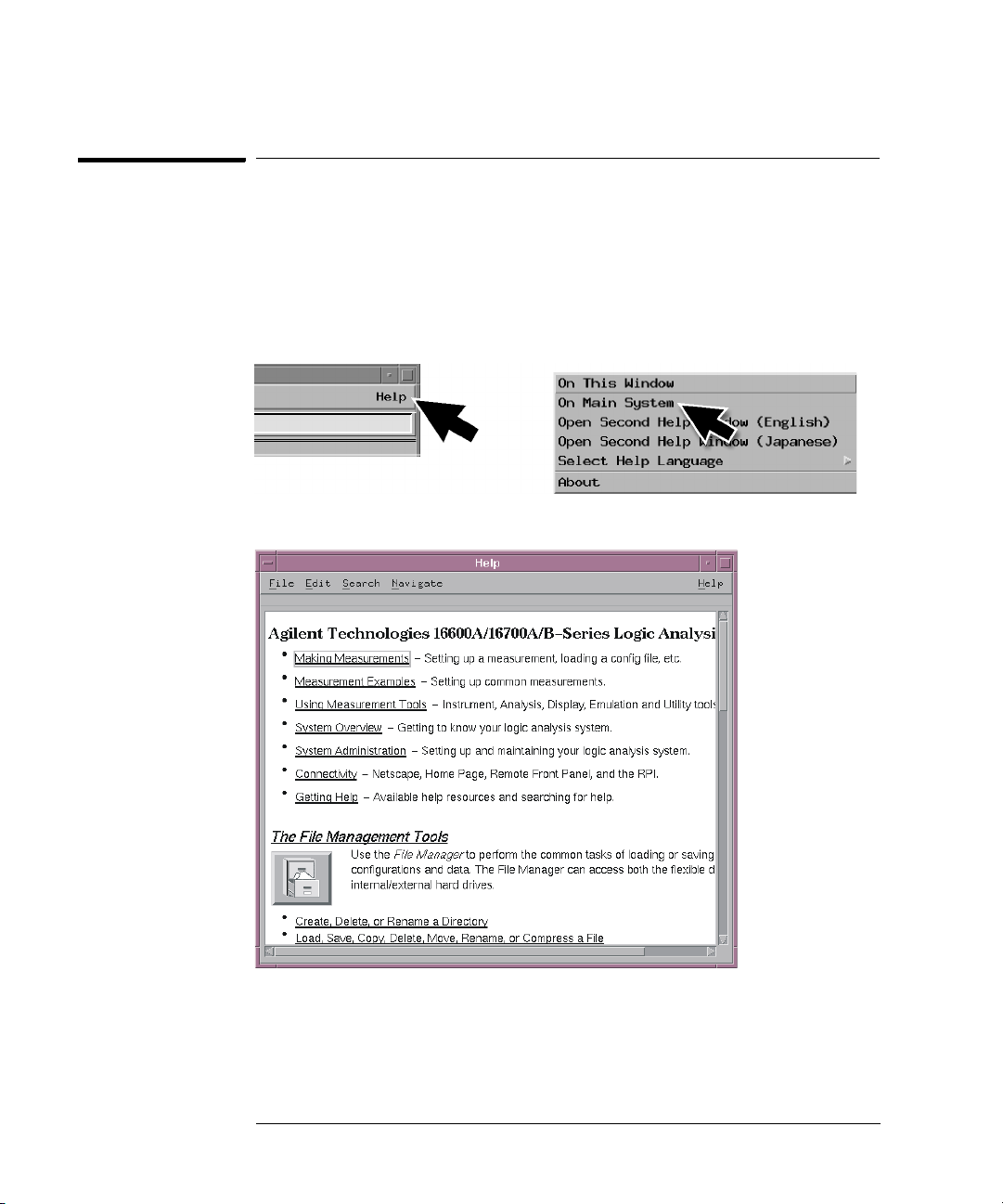
To locate information on using the logic analyzer
To locate information on using the logic analyzer
Go to on-line help for information on using your logic analyzer. A pdf file of the
on-line help is on the CD that came with your system if you want to print it
out.
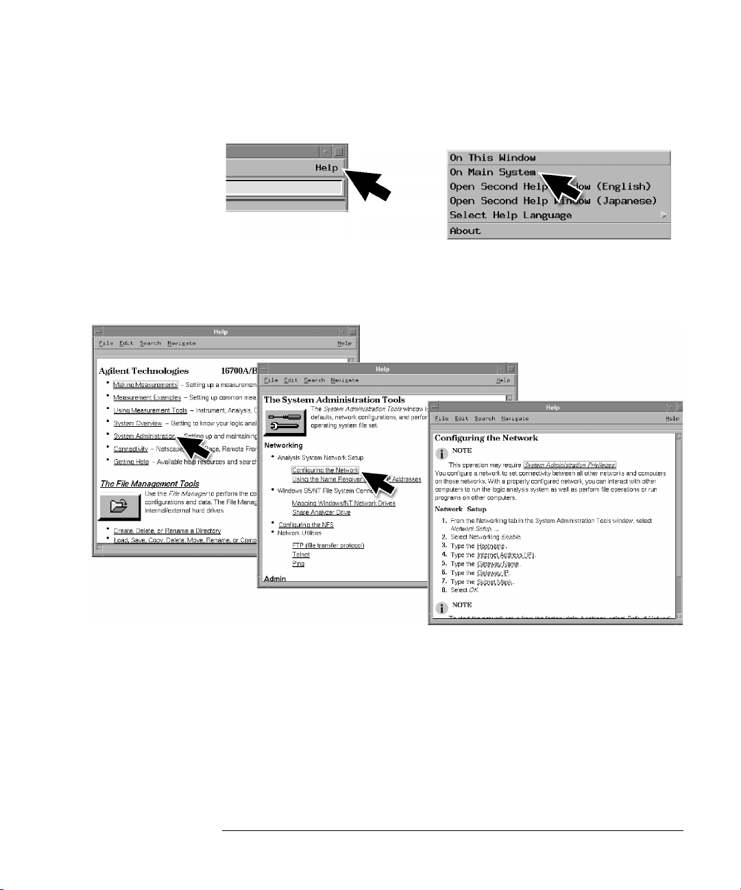
1 Select Help in the upper right corner of the screen and then select On
Main System.
2 Select the task you need information about. .
10
Page 11
Chapter 1: General Information
To locate specifications and characteristics
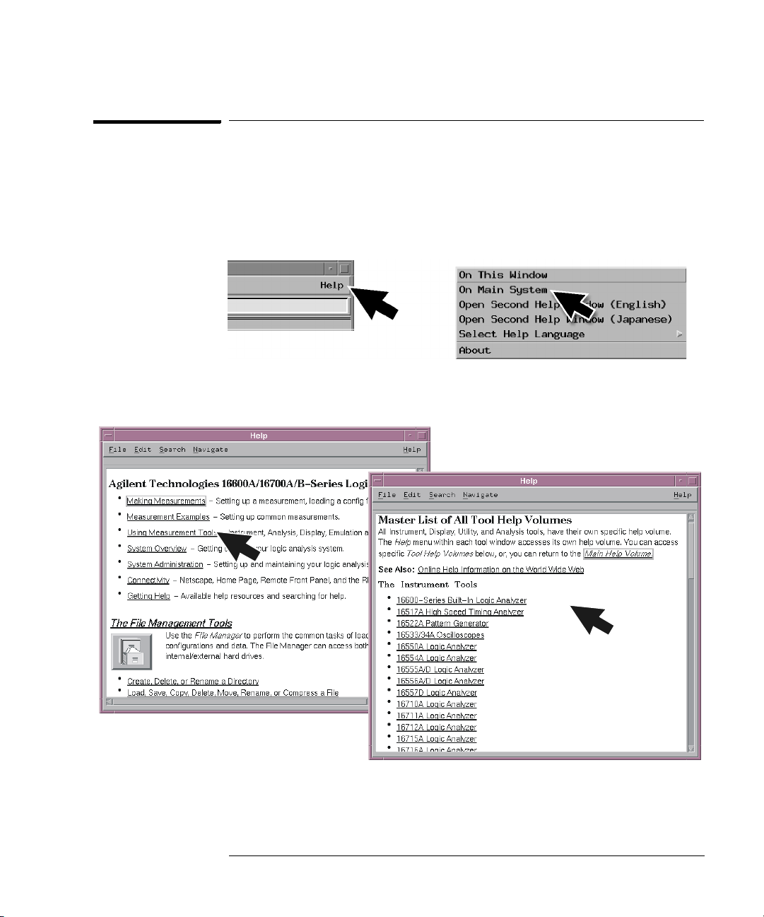
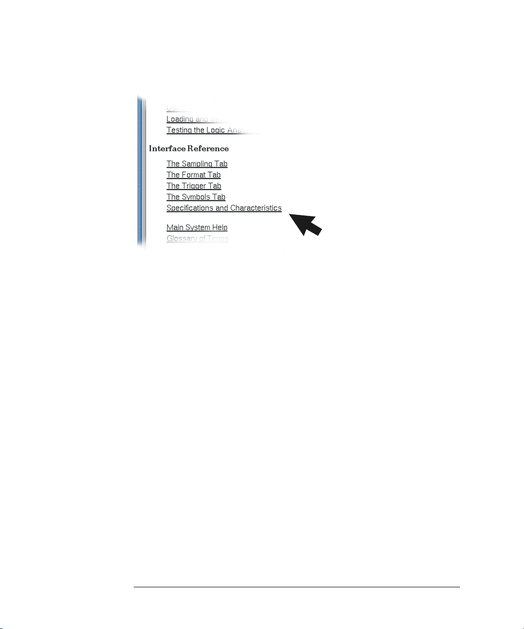
To locate specifications and characteristics
The specifications and characteristics for your instrument and measurement
module are in the on-line Help.
1 Select Help in the upper right corner of the screen and then select On
Main System.
2 Select Using Measurement Tools and then select your instrument or
measurement module from the list.
11
Page 12
Chapter 1: General Information
To locate specifications and characteristics
3 Under Interface Reference, select Specifications and Characteristics.
12
Page 13
Chapter 1: General Information
To create a backup file of your system settings and license passwords
To create a backup file of your system settings and
license passwords
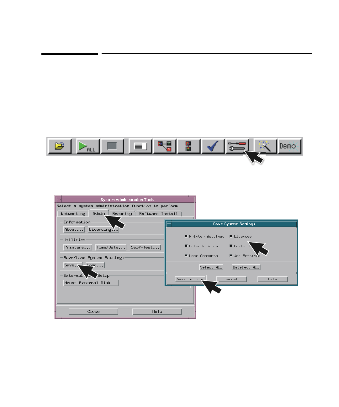
By saving your system settings to a flexible disk or a mounted directory, you
create a backup file that can be used to quickly setup systems or to restore
current system settings in case of problems.
1 Insert a flexible disk or set up a mounted directory.
2 Select the Tools icon from the menu bar.
3 Select the Admin tab and select Save, then select Licenses and Save to
File.
13
Page 14
Chapter 1: General Information
To create a backup file of your system settings and license passwords
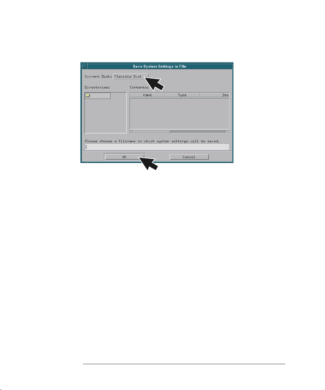
4 Select Flexible Disk or a Mounted Directory and then select OK.
14
Page 15
Chapter 1: General Information
To reload system settings and license passwords
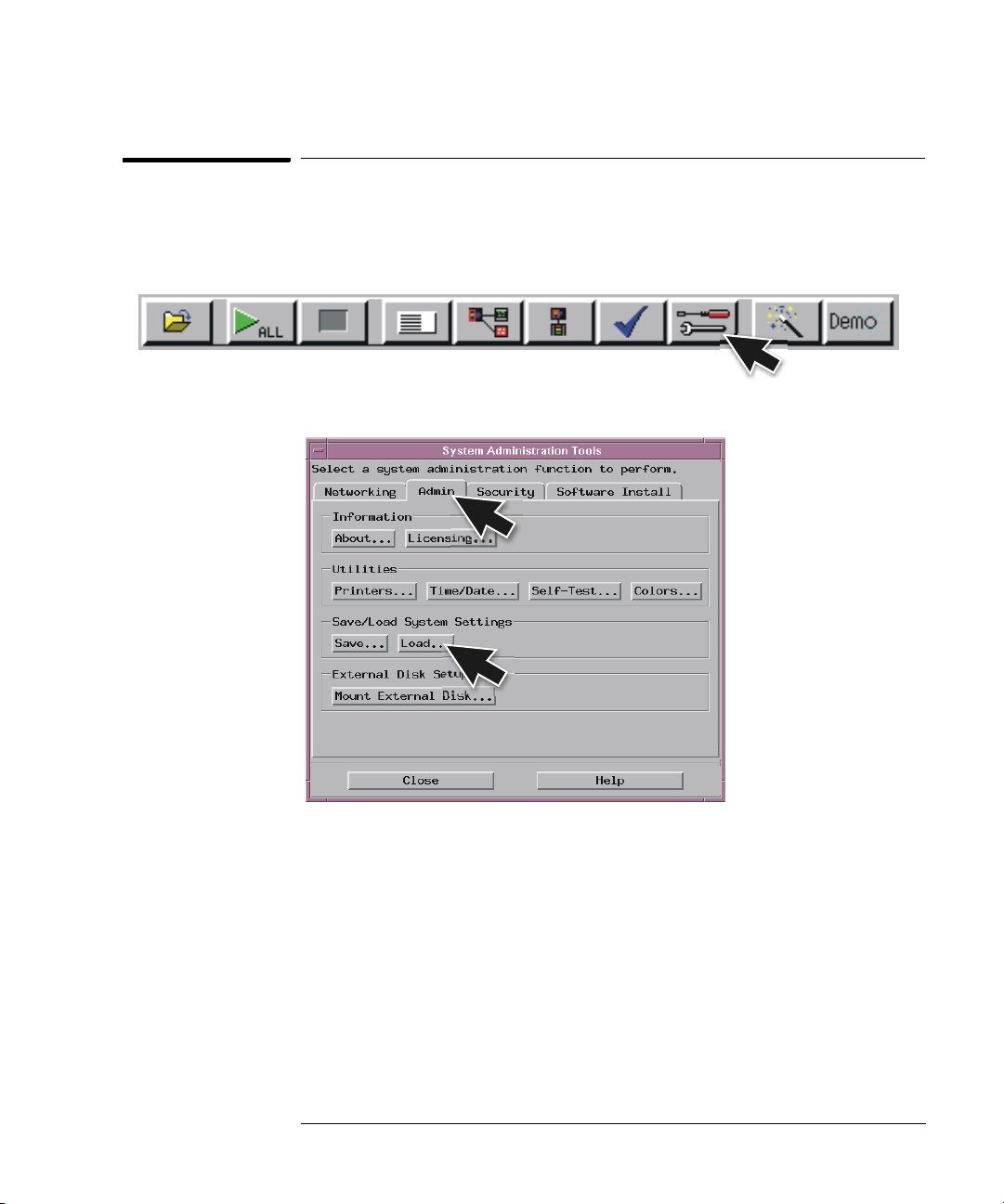
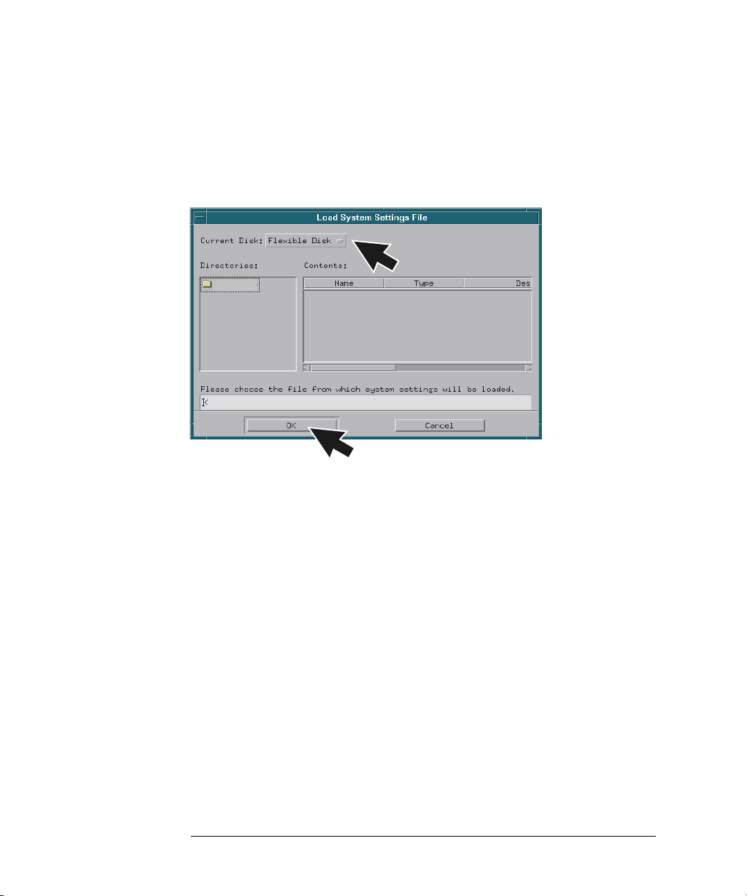
To reload system settings and license passwords
1 Insert the flexible disk or set up a mounted directory.
2 Select the Tools icon from the menu bar.
3 Go to the Admin tab and select Load.
15
Page 16
Chapter 1: General Information
To reload system settings and license passwords
4 Select Flexible Disk or Mounted Directory and select OK.
If an item is not valid, or was not initially saved to the file, the selection will be
grayed out in the interface. Also, if no file extension is added, a ‘.set’ extension
is automatically added for you.
16
Page 17

2
Connecting and Configuring Hardware
17
Page 18
Chapter 2: Connecting and Configuring Hardware
To connect the mouse, keyboard, and monitor
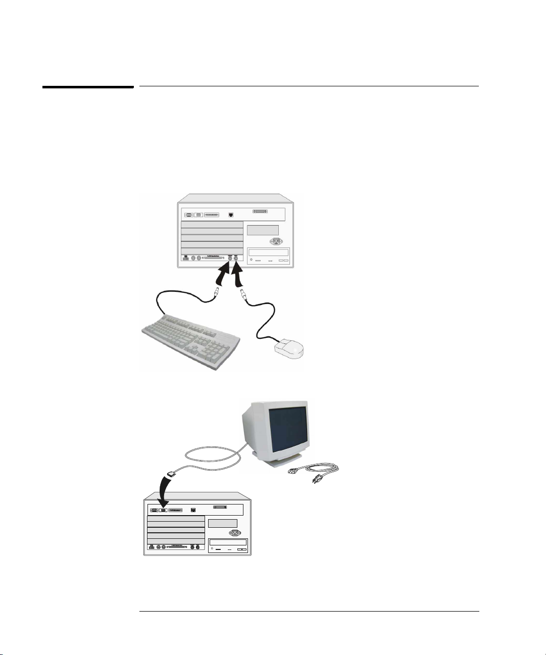
To connect the mouse, keyboard, and monitor
The 16700B must have the system mouse and keyboard connected for the
system to boot up properly. Once enabled on the LAN, the system can be
operated remotely without a keyboard or mouse. Use of a monitor is optional
for the 16700B and 16702B.
1 Connect the mouse and keyboard to the back of the 16700B or 16702B.
2 Connect the optional monitor to the back of the 16700B or 16702B.
3 Connect the monitor power cable. International versions of the power
cables can be found in the accessories box.
18
Page 19
Chapter 2: Connecting and Configuring Hardware
To configure a monitor for the 16700B
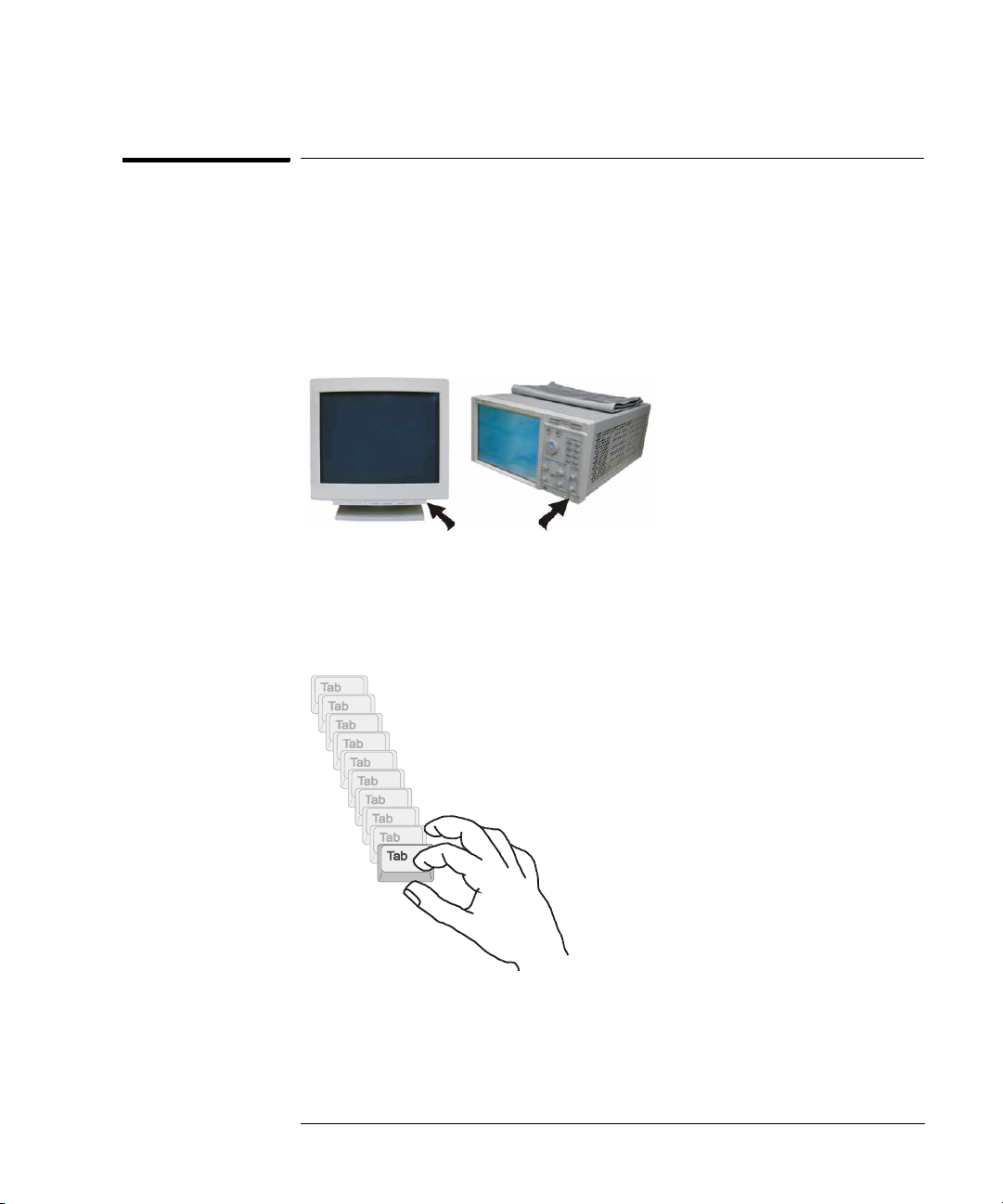
4 Allow a minimum of 5 cm spacing between instruments for proper
cooling.
5cm
16700B
5cm
16702B
5cm
5cm
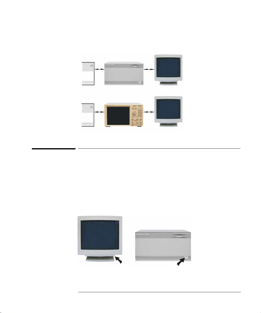
To configure a monitor for the 16700B
If you ordered the optional monitor with your logic analyzer, the monitor
resolution setting is pre-configured for 1280 x 1024 at the factory. Use this
procedure if you wish to configure an external monitor other than the optional
monitor orderable with the 16700B.
1 Connect your monitor to the logic analysis system as shown on page 18.
2 Turn on power to the monitor and then to the logic analysis system.
1
19
2
Page 20
Chapter 2: Connecting and Configuring Hardware
To configure a monitor for the 16700B
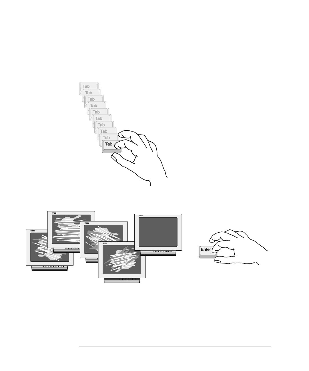
3 Immediately press the TAB key. Press once per second for
approximately 30 seconds.
every few seconds as the system cycles through the monitor resolution
choices.
The monitor display will change on the screen
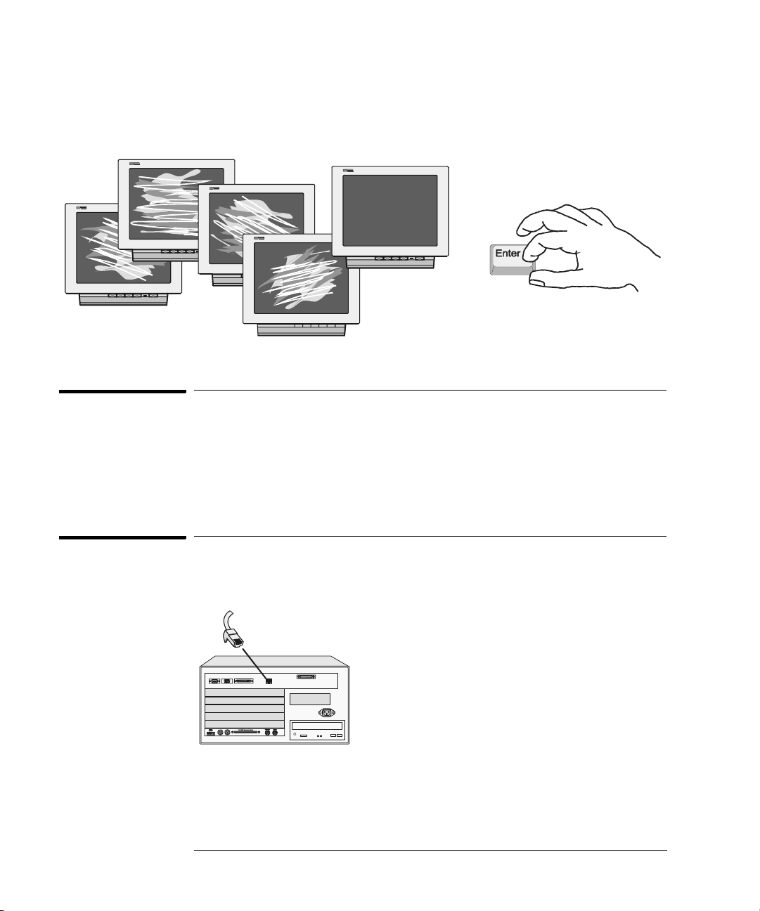
4 Press ENTER when you see a clear image to select your monitor choice
and type ‘Y” to confirm.
Clear
Images
20
Page 21
Chapter 2: Connecting and Configuring Hardware
To configure an optional monitor for the 16702B
To configure an optional monitor for the 16702B
The internal LCD display is pre-configured for 800 x 600 at the factory. Use
this procedure if you wish to configure an external monitor or change the
monitor setting to a different resolution.
1 Connect your monitor to the logic analysis system as shown on page 18.
2 Turn on power to the monitor and then to the logic analysis system.
1
2
3 Immediately press the TAB key. Press once per second for
approximately 30 seconds. The display will change on the screen every
few seconds as the system cycles through the monitor resolution
choices.
21
Page 22
Chapter 2: Connecting and Configuring Hardware
To change monitors (16700B or 16702B)
4 Press ENTER when you see a clear image to select your monitor choice
and type ‘Y” to confirm.
Clear
Images
To change monitors (16700B or 16702B)
Any time you change monitors you will need to re-configure the new monitor.
Follow the instructions beginning with step one on page 19 if you have a
16700B or page 21 if you have a 16702B.
To connect to LAN
1 Connect the LAN cable to the back of the16700B or 16702B.
10Base-T/100Base-TX
22
Page 23
Chapter 2: Connecting and Configuring Hardware
To connect to LAN
2 Go to the Help menu and select On Main System.
3 In the Help window select System Administration and then select
Configuring the Network. Follow the instructions on configuring the
network.
23
Page 24
Chapter 2: Connecting and Configuring Hardware
To connect a printer
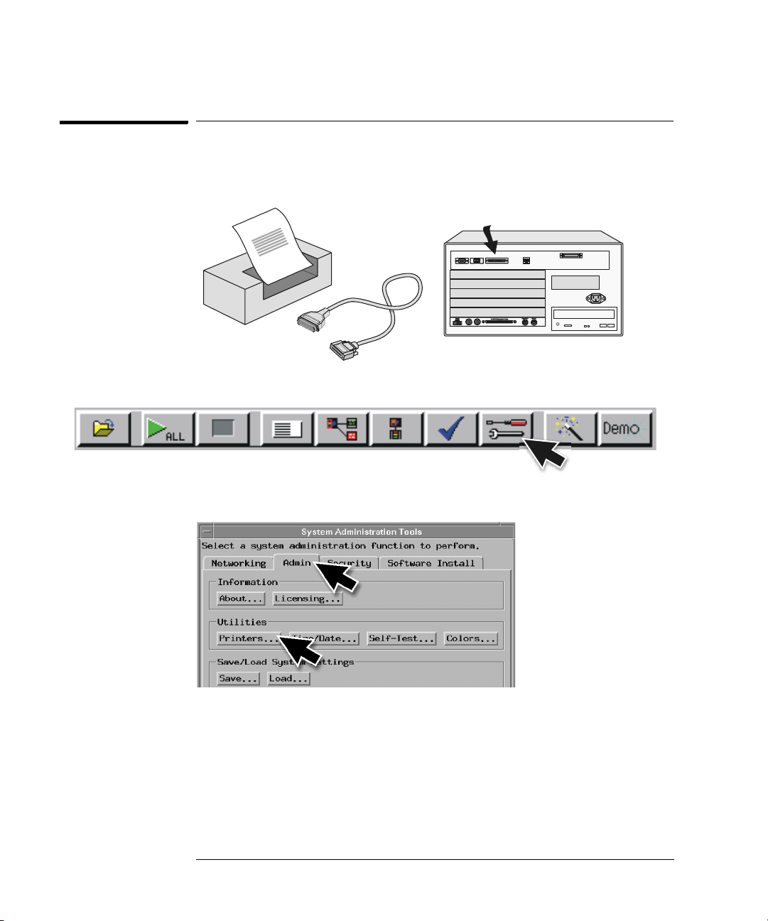
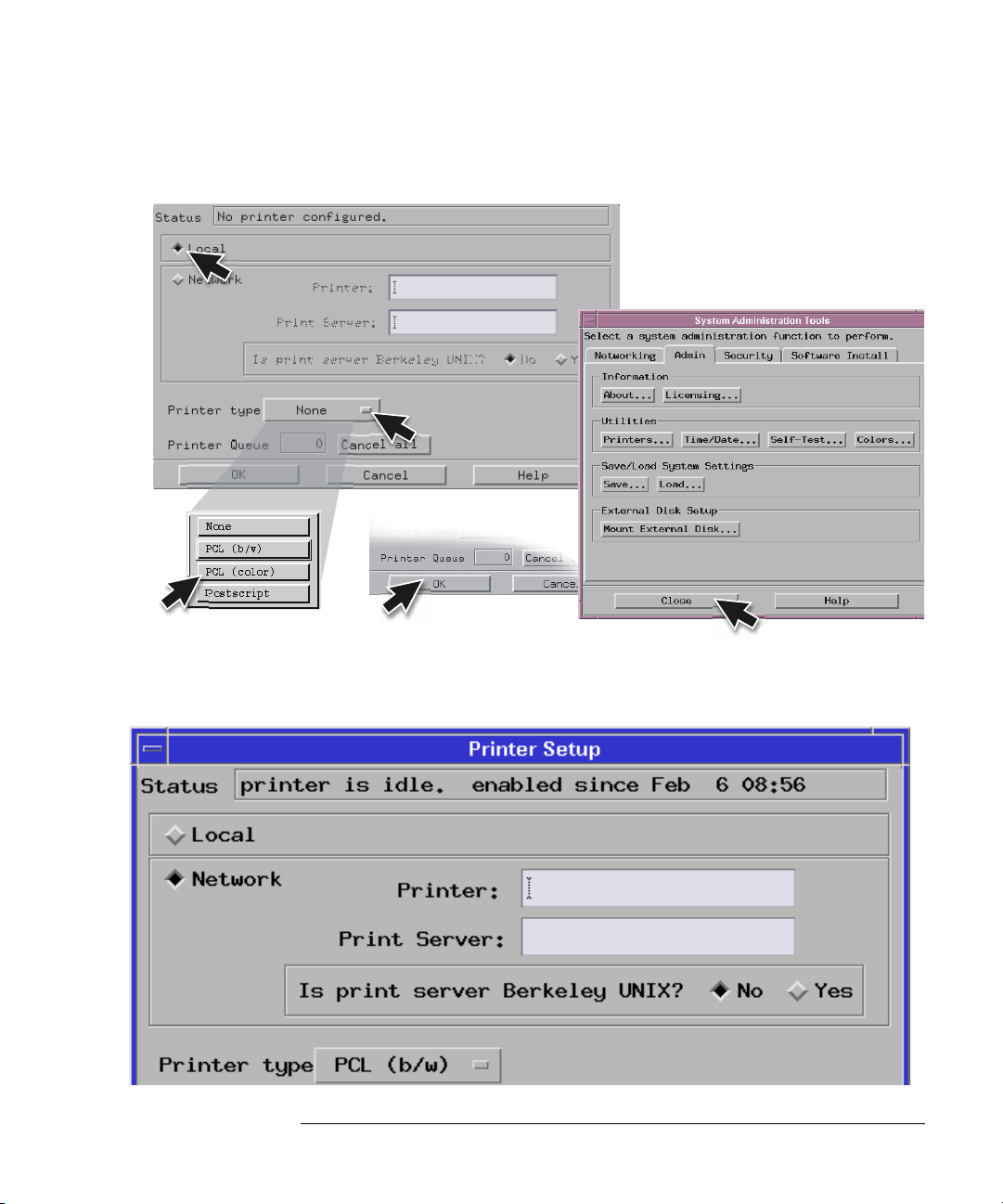
To connect a printer
1 Connect the printer cable to the back of your 16700B or 16702B.
2 Select the Tools icon from the menu bar.
3 Go to the Admin. tab and select Printers.
24
Page 25
(Your
printer)
Chapter 2: Connecting and Configuring Hardware
To connect a printer
4 If you are connecting a local printer, select Local, select your printer
type, select OK, and then Close.
5 If you are connecting a network printer, select Network, enter the
printer name, server address, select type, select OK, and then Close.
25
Page 26
Chapter 2: Connecting and Configuring Hardware
To connect an external data drive (option 008)
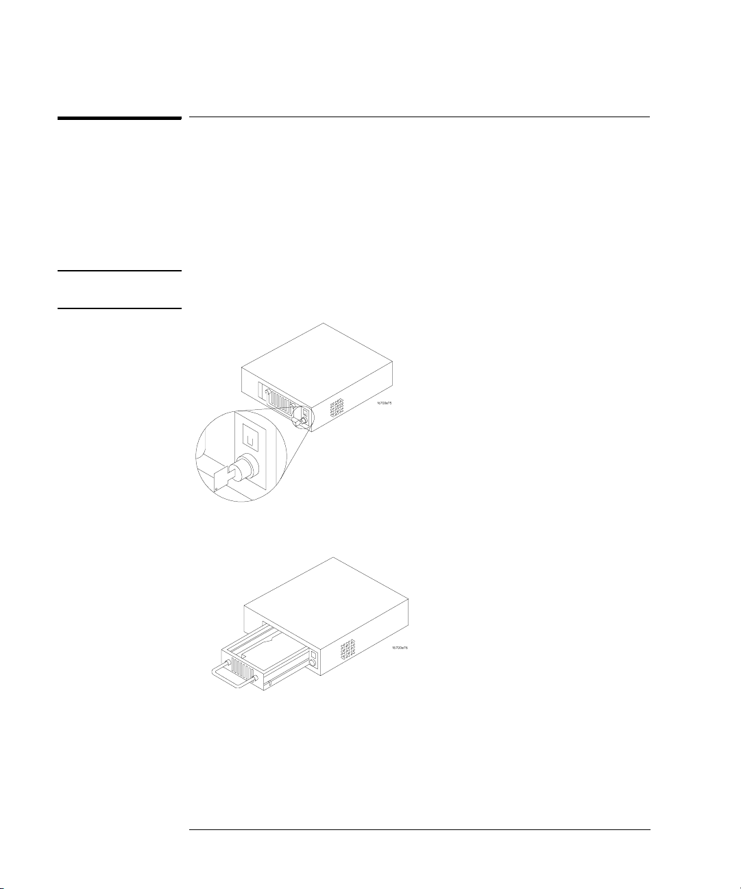
To connect an external data drive (option 008)
1 Power up the data drive.
2 Set the address.
a Unlock the data drive carrier. Wait until the drive stops spinning and
a “u” is displayed as shown.
CAUTION: Damage could result to the data drive if it is removed from the carrier while
the number is flashing.
b Remove the data drive from the carrier.
26
Page 27
Chapter 2: Connecting and Configuring Hardware
To connect an external data drive (option 008)
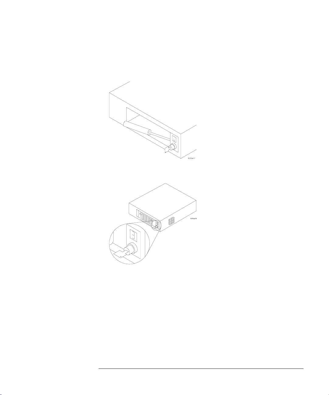
c Set the external data drive address to 3 or 4 using the alignment
tool supplied with the drive. The rotating switch is located inside
the carrier.
d Insert the disk drive into the carrier and lock it into place.
3 Power down the data drive.
27
Page 28
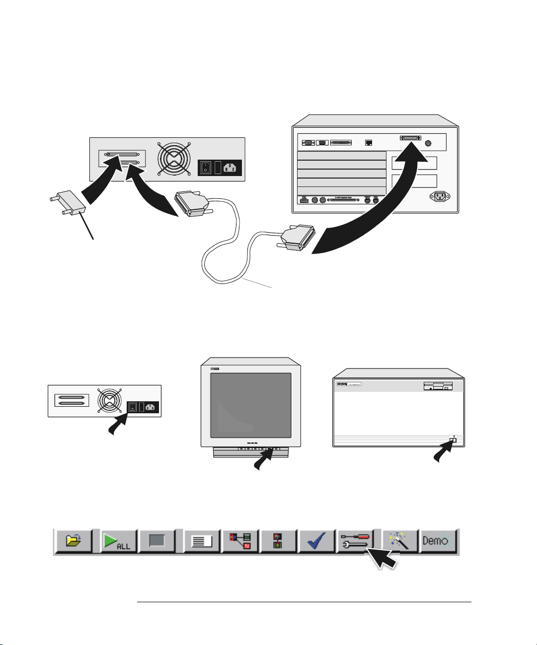
4 Connect the data drive to the SCSI-II port.
Termination Plug
(68 pin)
5 Power up the data drive, then the monitor, and then the system
Chapter 2: Connecting and Configuring Hardware
To connect an external data drive (option 008)
16700B or 16702B
(68 pin)
(50 pin)
External Disk Drive
Cable
(16700B or 16702B).
16700A
16700B or 16702B
6 Mount the disk.
a Select the Tools icon from the menu bar
28
Power
Busy
Page 29
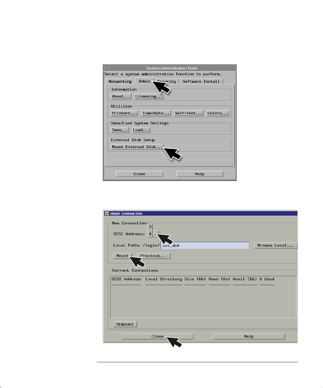
Chapter 2: Connecting and Configuring Hardware
To connect an external data drive (option 008)
b Go to the Admin. tab and select Mount External Disk.
c Select SCSI Address to the same number set in step 2, then Mount,
and Close.
29
Page 30
Chapter 2: Connecting and Configuring Hardware
To disconnect an external data drive (option 008)
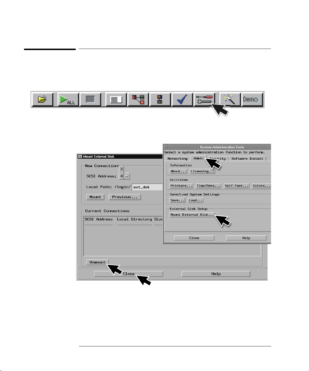
To disconnect an external data drive (option 008)
It is important that you unmount the disk before turning the system off.
1 Select the Tools icon from the menu bar.
2 Select the Admin. tab, select Mount External Disk, select Unmount,
and then Close.
30
Page 31

16700A
16700B or 16702B
Chapter 2: Connecting and Configuring Hardware
To connect a removable boot drive (option 009)
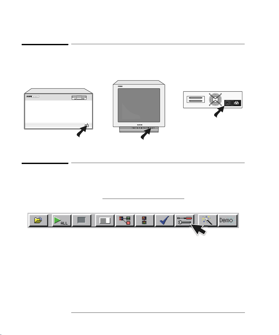
3 Turn the power off on the system, then the monitor, and then the data
drive.
Power
Busy
To connect a removable boot drive (option 009)
1 Power up the boot drive.
2 Set the address.
a Unlock the boot drive carrier. Wait until the drive stops spinning and
a “u” is displayed as shown.
CAUTION: Damage could result to the data drive if it is removed from the carrier while
the number is flashing.
31
Page 32

Chapter 2: Connecting and Configuring Hardware
To connect a removable boot drive (option 009)
b Remove the boot drive from the carrier.
c Set the external boot drive address to 6 using the alignment tool
supplied with the drive. The rotating switch is located inside the
carrier.
d Insert the disk into the carrier drive and lock it into place.
32
Page 33

3 Power down the boot drive.
4 Connect the boot drive to the SCSI-II port.
Termination Plug
(68 pin)
Chapter 2: Connecting and Configuring Hardware
To connect a removable boot drive (option 009)
16700B or 16702B
(68 pin)
(50 pin)
External Disk Drive
Cable
5 Power up the boot drive, then the monitor, and then the system.
16700A
16700B or 16702B
33
Power
Busy
Page 34
16700A
16700B or 16702B
Chapter 2: Connecting and Configuring Hardware
To disconnect a removable boot drive (option 009)
To disconnect a removable boot drive (option 009)
Turn the power off on the system, then the monitor, and then the boot drive.
Power
Busy
To install software
When a system is shipped, the factory installs the current operating system
and ordered processor support packages and tools. The latest software update
is available at www.software.cos.agilent.com/16700
1 Select the Tools icon from the menu bar.
34
.
Page 35

Chapter 2: Connecting and Configuring Hardware
2 Select the Software Install tab and then select Install.
To install software
3 Select the media type and select Apply. The resulting window will
display software that can be loaded.
35
Page 36

Chapter 2: Connecting and Configuring Hardware
To install software
4 To load System Software, highlight it and select Install.
5 To load Additional Tools or Processor Support Software:
a Double click to display the available packages.
b Select one or more desired packages. A second click on a
highlighted item will deselect it.
c Select Install and the system will automatically reboot if it is
required by the newly installed package.
36
Page 37

Chapter 2: Connecting and Configuring Hardware
16701B Expander Frame
To connect a 16701B expander frame
To connect a 16701B expander frame
1 Install your measurement modules in the 16701B expander frame.
Module installation instructions are on page 42. For information on
specific measurement modules go to:
Module Type Page
Logic Analyzer 45
Oscilloscope 71
Pattern Generator 87
2 Connect either a 30 cm (12 inch) or 90 cm (36 inch) interconnect cable
to the expander and system frames.
3 Tighten the connector screws with the screwdriver provided.
4 Connect the power cable to the 16701B.
5 Power up the 16700B or 16702B system.
16700B or 16702B
Screwdriver
16701B
Interconnect
Cable
37
Page 38

Chapter 2: Connecting and Configuring Hardware
To connect multiple frames
To connect multiple frames
As many as eight 16700B’s and/or 16702B’s with expander frames may be
connected together. To connect multiple frames you need to order 16700B
option #012 and/or 16702B option #012.
NOTE: The multiframe module requires software Rev. A.02.00.00 or higher. Agilent
16700B and 16702B logic analysis systems ordered with the multiframe option
installed will have the current operating system software installed.
1 If the multiframe module is already installed, skip to step 11.
2 End your logic analysis session.
a Exit all logic analysis sessions. In the session manager, select
Shutdown.
b At the query, select Powerdown.
c When the “OK to turn off power or reset system” message appears,
turn the instrument off.
d Remove power from the instrument.
3 Disconnect the power cable and all data and peripheral cables from the
rear panel.
4 Move the instrument to a static-safe work area.
5 Lay the instrument on its side so the handle side is up.
6 Using a Torx T10 screwdriver, remove two feet and one screw at the
center rear of the cover that secures the bottom cover to the frame.
38
Page 39

Chapter 2: Connecting and Configuring Hardware
To connect multiple frames
7 Slide the bottom cover toward the rear of the instrument and away..
8 Remove the cover plate.
39
Page 40

Chapter 2: Connecting and Configuring Hardware
To connect multiple frames
9 Insert the Multiframe Module with the cable attached.
16700e24.cdr
40
Page 41

Chapter 2: Connecting and Configuring Hardware
To connect multiple frames
10 Connect the Multiframe Module cable to the connector on the bottom
side of the Interface Board, insert the screws and reassemble the
frame.
16700e25.cdr
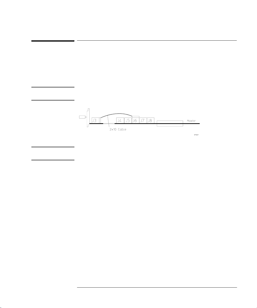
11 Connect mainframe and expander frames together.The frame at the
beginning of the series must have its INPUT port open and the last
frame in the series must have its OUTPUT port open.
Input port open on first frame
Output port open on last frame
41
Page 42

Chapter 2: Connecting and Configuring Hardware
To install, remove, or replace measurement modules
To install, remove, or replace measurement modules
CAUTION: Electrostatic discharge can damage electronic components. Use grounded
wrist straps and mats when performing any service to measurement modules.
NOTE: Measurement modules with different model numbers may not be connected
together in multi-card (Master/Expander) modules unless stated otherwise.
For information on specific measurement modules go to:
Module Type Page
Logic Analyzer 45
Oscilloscope 71
Pattern Generator 87
1 Power down the system and disconnect the power cable before
installing, removing or replacing measurement modules.
Power
Busy
2 Remove filler panels and carefully slide the module into the frame.
3 Gently apply pressure to the center of the module while tightening the
thumb screws.
42
Page 43

Chapter 2: Connecting and Configuring Hardware
Insert
or filler panels.
s
filler panels.)
To install, remove, or replace measurement modules
4 If you are inserting more than one module, the tightening order is
bottom module to top module. A single-module configuration can be
installed in any available slot.
module
Remove filler panels.
(Other or
modules
(Other or
modules
filler panels.)
5 Some modules require calibration if they are moved to a different slot.
For calibration information, refer to the on-line help for the individual
modules.
WARNING: For correct air circulation, filler panels must be installed in all unused card
slots. Correct air circulation keeps the instrument from overheating. Keep
any extra filler panels for future use.
43
Page 44

Chapter 2: Connecting and Configuring Hardware
To install, remove, or replace measurement modules
44
Page 45

3
Installing Logic Analyzer Measurement Modules
45
Page 46

Chapter 3: Installing Logic Analyzer Measurement Modules
Software Requirements
Software Requirements
The following table gives you the software version required in your 16700A/B
or 16702A/B mainframe for use with logic analyzer measurement modules. For
software installation instructions go to page page 34
Model Number Software Version
16517/18A All versions
16557D All versions
16710/11/12A A.01.20.00 or higher
16715/16/17A A.01.40.00 or higher
16718/19A A.01.50.00 or higher
16740/41/42A A.02.50.00 or higher
16750/51/52A A.02.00.00 or higher
16750/51/52B A.02.50.00 or higher
16753/54/55/56A A.02.70.00 or higher
16760A A.02.20.00 or higher
.
46
Page 47

Chapter 3: Installing Logic Analyzer Measurement Modules
16517/18A Logic Analyzer (2-card module)
16517/18A Logic Analyzer (2-card module)
The 16517A is the master card and the 16518A is the expander card. Connect
the cards together in one of the two ways shown below.
NOTE: Turn off the mainframe power before removing, replacing, or installing
modules following the procedures on page 42.
2 Connector
Cable
Expander
Expander (16518A)
Master (16517A)
Master (16517A)
Expander (16518A)
Master
Expander
Master
2 Connector
Cable
47
Page 48

Chapter 3: Installing Logic Analyzer Measurement Modules
16517/18A Logic Analyzer (3-card module)
16517/18A Logic Analyzer (3-card module)
The 16517A is the master card and the 16518A cards are expander cards.
Connect the cards together in one of the three ways shown below.
NOTE: Turn off the mainframe power before removing, replacing, or installing
modules following the procedures on page 42.
3 Connector
Master
Cable
2 Connector
Cable
Master (16517A)
Expander (16518A)
Expander (16518A)
Expander (16518A)
Master (16517A)
Expander (16518A)
Master
Expander
Expander
2 Connector
Cable
Expander
Expander
3 Connector
Cable
Expander (16518A)
Expander (16518A)
Master (16517A)
Expander
Expander
Master
48
Page 49

Chapter 3: Installing Logic Analyzer Measurement Modules
C
3 Connector
16517/18A Logic Analyzer (4-card module)
16517/18A Logic Analyzer (4-card module)
The 16517A is the master card and the 16518A cards are expander cards.
Connect the cards together in one of the two ways shown below.
NOTE: Turn off the mainframe power before removing, replacing, or installing
modules following the procedures on page 42.
2
onnector
Cable
Expander (16518A)
Master (16517A)
Expander (16518A)
Expander (16518A)
Expander
Master
Expander
Expander
3 Connector
Cable
Expander (16518A)
Expander (16518A)
Master (16517A)
Expander (16518A)
Cable
Expander
Expander
Master
Expander
2 Connector
Cable
49
Page 50

Chapter 3: Installing Logic Analyzer Measurement Modules
3 Connector
16517/18A Logic Analyzer (5-card module)
16517/18A Logic Analyzer (5-card module)
The 16517A is the master card and the 16518A cards are expander cards.
Connect the cards together as shown below.
NOTE: Turn off the mainframe power before removing, replacing, or installing
modules following the procedures on page 42.
Cable
Expander (16518A)
Expander (16518A)
Master (16517A)
Expander (16518A)
Expander (16518A)
Expander
Expander
Master
Expander
Expander
3 Connector
Cable
16557D Logic Analyzer (1-card module)
When ordered as a single card, the 16557D is shipped with a 2 x 10 cable
factory configured as a single-card module.
NOTE: Turn off the mainframe power before removing, replacing, or installing
modules following the procedures on page 42.
2x10 Cable
Master
50
Page 51

Chapter 3: Installing Logic Analyzer Measurement Modules
2x10 Cables
16557D Logic Analyzer (2-card module)
16557D Logic Analyzer (2-card module)
Use two 2 x 25 cables and two 2 x 10 cables to connect the cards as shown.
NOTE: Turn off the mainframe power before removing, replacing, or installing
modules following the procedures on page 42.
Expander
Master
2x25 Cables
Expander
Master
(Need 2)
51
Page 52

Chapter 3: Installing Logic Analyzer Measurement Modules
2x25 Cables
2x10 Cables
16557D Logic Analyzer (3-card module)
16557D Logic Analyzer (3-card module)
Use two 2 x 25 cables and three 2 x 10 cables to connect the cards as shown.
NOTE: Turn off the mainframe power before removing, replacing, or installing
modules following the procedures on page 42.
(Need 2)
Expander
Master
Expander
Expander
Master
Expander
52
Page 53

Chapter 3: Installing Logic Analyzer Measurement Modules
2x25 Cables
16557D Logic Analyzer (3-card module)
16557D Logic Analyzer (3-card module)
Use two 2 x 25 cables and four 2 x 10 cables to connect the cards as shown.
NOTE: Turn off the mainframe power before removing, replacing, or installing
modules following the procedures on page 42.
(Need 2)
Expander
Expander
Master
Expander
2x10 Cables
Expander
Expander
Master
Expander
53
Page 54

Chapter 3: Installing Logic Analyzer Measurement Modules
2x25 Cables
16557D Logic Analyzer (5-card module)
16557D Logic Analyzer (5-card module)
Use two 2 x 25 cables and five 2 x 10 cables to connect the cards as shown.
NOTE: Turn off the mainframe power before removing, replacing, or installing
modules following the procedures on page 42.
(Need 2)
Expander
Expander
Master
Expander
Expander
Master
Expander
Expander
Expander
Expander
2x10 Cables
54
Page 55

Chapter 3: Installing Logic Analyzer Measurement Modules
16710/11/12A Logic Analyzer (1-card module)
16710/11/12A Logic Analyzer (1-card module)
A single 16710/11/12A logic analyzer module will have the 2 x 40 cable
connected in the single-card configuration.
NOTE: Turn off the mainframe power before removing, replacing, or installing
modules following the procedures on page 42.
J9
J7
Master
J8
2x40 Cable
NOTE: Measurement modules with different model numbers may not be connected
together in multi-card (Master/Expander) modules.
55
Page 56

Chapter 3: Installing Logic Analyzer Measurement Modules
16710/11/12A Logic Analyzer (2-card module)
16710/11/12A Logic Analyzer (2-card module)
Connect two modules as shown using two 2 x 25 cables and two 2 x 40 cables.
NOTE: Turn off the mainframe power before removing, replacing, or installing
modules following the procedures on page 42.
2x40
Cable
J6
2x25
Cable
J5
Master
J5
Expander
J7
2x25
Cable
J6
J7
2x40
Cable
J9
J8
J9
J8
NOTE: Measurement modules with different model numbers may not be connected
together in multi-card (Master/Expander) modules.
56
Page 57
Chapter 3: Installing Logic Analyzer Measurement Modules
16715/16/17A, 16718/19A, 16740/41/42A, 16750/51/52A/B Logic Analyzer (1-card module)
16715/16/17A, 16718/19A, 16740/41/42A, 16750/51/52A/B
Logic Analyzer (1-card module)
Each card shipped stand-alone has the 2 x 10 cable connected in the singlecard module configuration. A single-card module can be installed in any
available slot.
NOTE: Turn off the mainframe power before removing, replacing, or installing
modules following the procedures on page 42.
NOTE: Measurement modules with different model numbers may not be connected
together in multi-card (Master/Expander) modules.
57
Page 58

Chapter 3: Installing Logic Analyzer Measurement Modules
16715/16/17A, 16718/19A, 16740/41/42A, 16750/51/52A/B Logic Analyzer (2-card module)
16715/16/17A, 16718/19A, 16740/41/42A, 16750/51/52A/B
Logic Analyzer (2-card module)
Use two 2 x 10 cables and two 2 x 40 cables (in the accessory pouch) to
connect the modules.
NOTE: Turn off the mainframe power before removing, replacing, or installing
modules following the procedures on page 42.
NOTE: Measurement modules with different model numbers may not be connected
together in multi-card modules. However, the 16750A works with the 16750B;
the 16751A works with the 16751B; the 16752A works with the 16752B.
58
Page 59

Chapter 3: Installing Logic Analyzer Measurement Modules
16715/16/17A, 16718/19A, 16740/41/42A, 16750/51/52A/B Logic Analyzer (3-card module)
16715/16/17A, 16718/19A, 16740/41/42A, 16750/51/52A/B
Logic Analyzer (3-card module)
Use three 2 x 10 cables and four 2 x 40 cables (in the accessory pouch) to
connect the modules.
NOTE: Turn off the mainframe power before removing, replacing, or installing
modules following the procedures on page 42.
NOTE: Measurement modules with different model numbers may not be connected
together in multi-card modules. However, the 16750A works with the 16750B;
the 16751A works with the 16751B; the 16752A works with the 16752B.
59
Page 60

Chapter 3: Installing Logic Analyzer Measurement Modules
16715/16/17A, 16718/19A, 16740/41/42A, 16750/51/52A/B Logic Analyzer (4-card module)
16715/16/17A, 16718/19A, 16740/41/42A, 16750/51/52A/B
Logic Analyzer (4-card module)
Use four 2 x 10 cables and six 2 x 40 cables (in the accessory pouch) to
connect the modules.
NOTE: Turn off the mainframe power before removing, replacing, or installing
modules following the procedures on page 42
NOTE: Measurement modules with different model numbers may not be connected
together in multi-card modules. However, the 16750A works with the 16750B;
the 16751A works with the 16751B; the 16752A works with the 16752B.
60
Page 61

Chapter 3: Installing Logic Analyzer Measurement Modules
16715/16/17A, 16718/19A, 16740/41/42A, 16750/51/52A/B Logic Analyzer (5-card module)
16715/16/17A, 16718/19A, 16740/41/42A, 16750/51/52A/B
Logic Analyzer (5-card module)
Use five 2 x 10 cables and eight 2 x 40 cables (in the accessory pouch) to
connect the modules
NOTE: Turn off the mainframe power before removing, replacing, or installing
modules following the procedures on page 42.
NOTE: Measurement modules with different model numbers may not be connected
together in multi-card modules. However, the 16750A works with the 16750B;
the 16751A works with the 16751B; the 16752A works with the 16752B.
61
Page 62

Chapter 3: Installing Logic Analyzer Measurement Modules
16753/54/55/56A Logic Analyzer (1-card module)
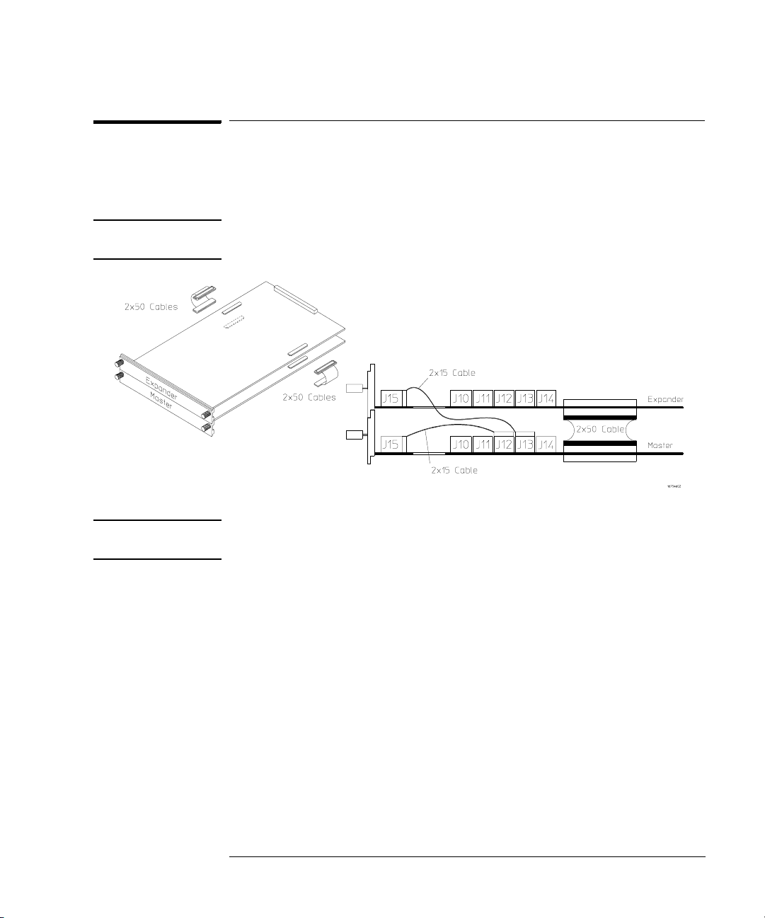
16753/54/55/56A Logic Analyzer (1-card module)
Each card shipped stand-alone has the 2 x 15 cable connected in the singlecard module configuration. The 2 x 50 cables in the accessory pouch are not
used. A single-card module can be installed in any available slot.
NOTE: Turn off the mainframe power before removing, replacing, or installing
modules following the procedures on page 42.
62
Page 63
Chapter 3: Installing Logic Analyzer Measurement Modules
16753/54/55/56A Logic Analyzer (2-card module)
16753/54/55/56A Logic Analyzer (2-card module)
Use two 2 x 15 cables and two 2 x 50 cables (in the accessory pouch) to
connect the modules.
NOTE: Turn off the mainframe power before removing, replacing, or installing
modules following the procedures on page 42.
NOTE: Measurement modules with different model numbers can be mixed in multi-
card modules.
63
Page 64

Chapter 3: Installing Logic Analyzer Measurement Modules
16753/54/55/56A Logic Analyzer (3-card module)
16753/54/55/56A Logic Analyzer (3-card module)
Use three 2 x 15 cables and four 2 x 50 cables (in the accessory pouch) to
connect the modules.
NOTE: Turn off the mainframe power before removing, replacing, or installing
modules following the procedures on page 42.
NOTE: Measurement modules with different model numbers can be mixed in multi-
card modules.
64
Page 65

Chapter 3: Installing Logic Analyzer Measurement Modules
16753/54/55/56A Logic Analyzer (4-card module)
16753/54/55/56A Logic Analyzer (4-card module)
Use four 2 x 15 cables and six 2 x 50 cables (in the accessory pouch) to
connect the modules.
NOTE: Turn off the mainframe power before removing, replacing, or installing
modules following the procedures on page 42
NOTE: Measurement modules with different model numbers can be mixed in multi-
card modules.
65
Page 66

Chapter 3: Installing Logic Analyzer Measurement Modules
16753/54/55/56A Logic Analyzer (5-card module)
16753/54/55/56A Logic Analyzer (5-card module)
Use five 2 x 15 cables and eight 2 x 50 cables (in the accessory pouch) to
connect the modules
NOTE: Turn off the mainframe power before removing, replacing, or installing
modules following the procedures on page 42.
NOTE: Measurement modules with different model numbers can be mixed in multi-
card modules.
66
Page 67

Chapter 3: Installing Logic Analyzer Measurement Modules
16760A Logic Analyzer (1-card module)
16760A Logic Analyzer (1-card module)
A single 16760A logic analyzer module will have the 2 x 10 cable connected in
the single-card configuration.
NOTE: Turn off the mainframe power before removing, replacing, or installing
modules following the procedures on page 42.
16760A Logic Analyzer (2-card module)
Use two 2 x 10 cables and two 2 x 40 cables (in the accessory pouch) to
connect the modules.
NOTE: Turn off the mainframe power before removing, replacing, or installing
modules following the procedures on page 42.
67
Page 68

Chapter 3: Installing Logic Analyzer Measurement Modules
16760A Logic Analyzer (3-card module)
16760A Logic Analyzer (3-card module)
Use three 2 x 10 cables and four 2 x 40 cables (in the accessory pouch) to
connect the modules.
NOTE: Turn off the mainframe power before removing, replacing, or installing
modules following the procedures on page 42.
68
Page 69

Chapter 3: Installing Logic Analyzer Measurement Modules
16760A Logic Analyzer (4-card module)
16760A Logic Analyzer (4-card module)
Use four 2 x 10 cables and six 2 x 40 cables (in the accessory pouch) to
connect the modules.
NOTE: Turn off the mainframe power before removing, replacing, or installing
modules following the procedures on page 42.
69
Page 70

Chapter 3: Installing Logic Analyzer Measurement Modules
16760A Logic Analyzer (5-card module)
16760A Logic Analyzer (5-card module)
Use five 2 x 10 cables and eight 2 x 40 cables (in the accessory pouch) to
connect the modules.
NOTE: Turn off the mainframe power before removing, replacing, or installing
modules following the procedures on page 42.
70
Page 71

4
Installing Oscilloscope Measurement Modules
71
Page 72

Chapter 4: Installing Oscilloscope Measurement Modules
16700A
Power
Busy
16700B or 16702B
16533/34A Oscilloscope Module (single or multi-card modules)
16533/34A Oscilloscope Module (single or multi-card
modules)
The Agilent Technologies 16533A/34A oscilloscope module functions as either
a master card or expander card. It is compatible with all versions of software
in your 16700A/B or 16702A/B mainframe. The circuitry in the module
requires an operational accuracy calibration to optimize measurement
accuracy.
A multicard module should contain either all 16533A or 16534A cards.
NOTE: Each of the individual cards of a multicard 16533A or a multicard 16534A
module must first be calibrated as a single card. After reconfiguring into a
multicard module, the channel skew calibration needs to be done.
Step 1 Prepare a single 16533/34A card for calibration
CAUTION: The effects of ELECTROSTATIC DISCHARGE can damage components. Use
grounded wrist straps and mats when you are performing any kind of service
on this module.
1 Power down your 16700A/B or 16702A/B mainframe.
2 Remove all modules and filler panels from the mainframe and set the
PROTECTED/UNPROTECTED switch to UNPROTECTED.
72
Page 73

Chapter 4: Installing Oscilloscope Measurement Modules
D
16533/34A Oscilloscope Module (single or multi-card modules)
NOTE: If you calibrate a module without unprotecting the memory, the new
calibration settings will not be saved when the system is shut down. The
system will default to the previous settings. The new calibration settings
would be effective for the current active session only.
UNPROTECTE
PROTECTED
3 Reinstall the 16533/34A modules and filler panels into the mainframe.
73
Page 74

Chapter 4: Installing Oscilloscope Measurement Modules
Power
16533/34A Oscilloscope Module (single or multi-card modules)
4 Power up the monitor (if applicable) and then the system.
16700A
16700B or 16702B
Busy
5 For more accurate calibration, allow the system 30 minutes to warm
up.
0
15
30
74
Page 75

Chapter 4: Installing Oscilloscope Measurement Modules
16533/34A Oscilloscope Module (single or multi-card modules)
Step 2 Perform operational accuracy calibration
1 Connect the BNC Tee and the (equal length) 50-ohm BNC cables to the
module.
AC/DC Cal
Channel 1
Channel 2
2 In the Logic Analysis System window, select the module icon for the
16533A/34A to be calibrated, then select Calibration.
$
75
Page 76

Chapter 4: Installing Oscilloscope Measurement Modules
16533/34A Oscilloscope Module (single or multi-card modules)
3 In the Calibration window, select Default Factors. At the confirmation,
select OK to load the default factors.
4 Select the Run icon and the instrument will remind you to connect the
cables to the appropriate locations on the rear panel of the module.
Select OK and wait until the operational accuracy calibration is
complete.
RUN
76
Page 77

Chapter 4: Installing Oscilloscope Measurement Modules
16533/34A Oscilloscope Module (single or multi-card modules)
As operational accuracy calibration runs, messages appear in the message box
on screen.
The Calibration Status window indicates pass or fail as each operational
accuracy calibration routine is completed. The resulting calibration factors are
automatically stored to non-volatile RAM at the conclusion of each calibration
routine.
77
Page 78

Chapter 4: Installing Oscilloscope Measurement Modules
16533/34A Oscilloscope Module (single or multi-card modules)
Step 3 Calibrate a single card for external trigger skew
1 Connect a 9-inch 50-ohm BNC cable to one side of the BNC tee
adapter. On the other side of the BNC tee adapter connect a 9-inch 50ohm BNC and a BNC(f)/SMB(m) adapter.
AC/DC Cal
Channel 1
ECL
External
Tri gge r I n
BNC/SMB
Adapter
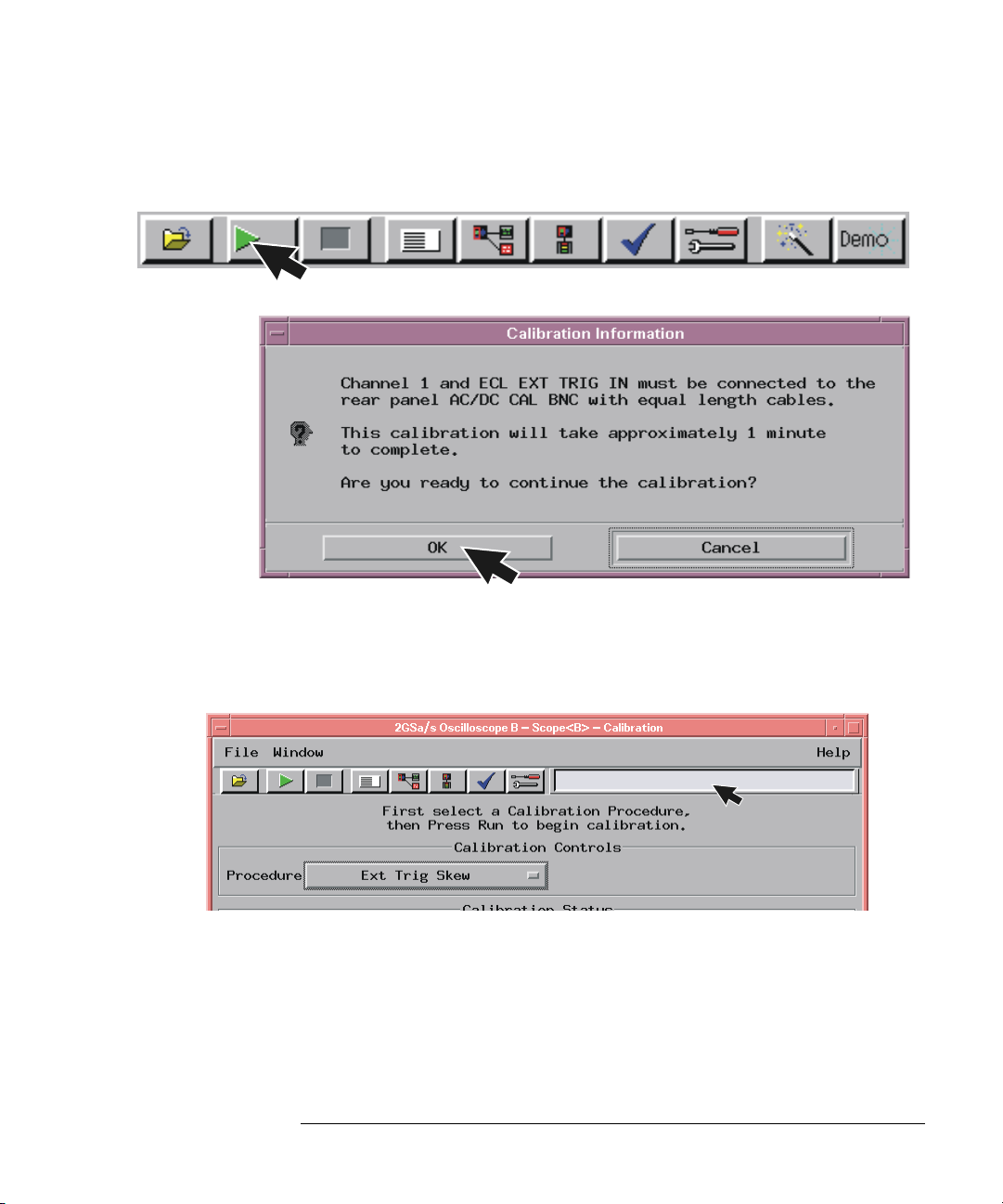
2 Select the Procedure field and then select Ext Trig Skew.
78
Page 79
Chapter 4: Installing Oscilloscope Measurement Modules
16533/34A Oscilloscope Module (single or multi-card modules)
3 Select the Run icon and the instrument will remind you to connect the
cables. Select OK and wait for the trigger skew calibration to complete.
RUN
As trigger skew calibration runs, messages appear in the message box on
screen. When the Ext Trig Skew calibration is complete, the resulting
calibration factors are stored in non-volatile RAM.
4 If a multi-card module is being calibrated, repeat the procedures
beginning with Step 1 on page 72 for each card until all cards have been
calibrated.
5 If all cards have been calibrated, remove the BNC cables from the
instrument.
6 Select Close in the Calibration window.
79
Page 80

Chapter 4: Installing Oscilloscope Measurement Modules
16533/34A Oscilloscope Module (single or multi-card modules)
7 In the Logic Analysis System window select File, then select Exit and
OK to close the session.
8 In the Session Manager window select Shutdown.
9 When the “OK to powerdown” message appears, turn off the power
switch.
80
Page 81

Chapter 4: Installing Oscilloscope Measurement Modules
16533/34A Oscilloscope Module (single or multi-card modules)
10 If you are only calibrating one card set the PROTECTED/
UNPROTECTED switch back to PROTECTED.
If only calibrating one
card set protect.
UNPROTECTED
PROTECTED
11 For multi-card modules, leave the switch set to UNPROTECTED and
continue to Step 4 to perform reconfiguration.
Step 4 Reconfigure multi-card modules
A multicard module should contain either all 16533A or 16534A cards.
1 After calibrating each card individually (following the procedures
beginning on page 72) and before applying power to the mainframe,
connect the module cables.
a Beginning with the top-most card, connect the ECL EXT TRIG OUT
to the ECL EXT TRIG IN of the card immediately below. Use the
master/expander trigger cable included with the accessory kit of
each card.
Master/expander
trigger cables
81
Page 82

Chapter 4: Installing Oscilloscope Measurement Modules
16533/34A Oscilloscope Module (single or multi-card modules)
b Repeat for all cards in the module. Up to 4 cards may be configured
on a single time base and trigger in a 16700A, 16700B, 16702A, or
16702B mainframe
2 Reapply power to the 16700-series mainframe.
3 In the Logic Analysis System window select the icon for the master
card of the multi-card module then select Calibration.
$
4 Perform channel skew calibration on the multi-card module.
a Connect two 9-inch 50-ohm BNC cables and a BNC tee adapter
between channel 1, AC/DC cal, of the first card and channel 1 of the
second card.
Chan. 1
Chan. 1
Chan. 2
Chan. 2
82
Channel 1
Upper Card
AC/CD Cal
Upper Card
Channel 1
Lower Card
Page 83

Chapter 4: Installing Oscilloscope Measurement Modules
16533/34A Oscilloscope Module (single or multi-card modules)
b Select the Procedure field and then select Ext Trig Skew.
c Select Run and the instrument will remind you to connect the
cables. Select OK and the Calibration window opens.
RUN
83
Page 84

Chapter 4: Installing Oscilloscope Measurement Modules
16533/34A Oscilloscope Module (single or multi-card modules)
d Select the Channels field, select two channels to deskew, select
Run, and follow the instructions on the display.
RUN
e Repeat the channel skew procedure until all channel combinations
have been deskewed.
5 Remove the BNC cables from the instrument.
6 Select Close in the Calibration window.
84
Page 85

Chapter 4: Installing Oscilloscope Measurement Modules
D
16533/34A Oscilloscope Module (single or multi-card modules)
7 In the Logic Analysis System window select File, then select Exit and
OK to close the session.
8 In the Session Manager window select Shutdown.
9 When the “OK to powerdown” message appears, turn off the power
switch.
10 Set the PROTECTED/UNPROTECTED switch back to PROTECTED.
UNPROTECTE
PROTECTED
85
Page 86

86
Page 87

5
Installing Pattern Generator Measurement Modules
87
Page 88

Chapter 5: Installing Pattern Generator Measurement Modules
Software Requirements
Software Requirements
The following table gives you the software version required in your 16700A/B
or 16702A/B mainframe for use with pattern generator measurement modules.
For software installation instructions go to page page 34
Model Number Software Version
16522A All versions
16720A A.02.00.00 or higher
.
16522A Pattern Generator (1-card module)
Each 16522A shipped stand-alone has the 2 x 10 cable connected in the
single-card module configuration. A single-card module can be installed in any
available slot.
NOTE: Turn off the mainframe power before removing, replacing, or installing
modules following the procedures on page 42.
2x10 cable
Master
88
Page 89

Chapter 5: Installing Pattern Generator Measurement Modules
16522A Pattern Generator (2-card module)
16522A Pattern Generator (2-card module)
Use two 2 x 10 cables to connect the modules as shown.
NOTE: Turn off the mainframe power before removing, replacing, or installing
modules following the procedures on page 42.
2x10 Cable
Expander
Master
16522A Pattern Generator (3-card module)
Use three 2 x 10 cables to connect the modules.
NOTE: Turn off the mainframe power before removing, replacing, or installing
modules following the procedures on page 42.
2x10 Cable
Expander
Master
Expander
89
Page 90

Chapter 5: Installing Pattern Generator Measurement Modules
16522A Pattern Generator (4-card module)
16522A Pattern Generator (4-card module)
NOTE: Turn off the mainframe power before removing, replacing, or installing
modules following the procedures on page 42.
1 Carefully slide the 4 cards half way into the mainframe slots.
2 Use four 2 x 10 cables to connect the modules. Cable the bottom
Expander Card to the Master Card first. Then cable the upper two
Expander Cards to the Master Card.
2x10 Cable
Expander
Expander
Master
Expander
3 Gently slide the cabled assembly fully into the frame and tighten the
thumb screws.
90
Page 91

Chapter 5: Installing Pattern Generator Measurement Modules
16522A Pattern Generator (5-card module)
16522A Pattern Generator (5-card module)
NOTE: Turn off the mainframe power before removing, replacing, or installing
modules following the procedures on page 42.
1 Carefully slide the 4 cards half way into the mainframe slots.
2 Use five 2 x 10 cables to connect the modules. Cable the bottom
Expander Card to the Master Card first. Then cable the upper two
Expander Cards to the Master Card.
2x10 Cable
Expander
Expander
Master
Expander
Expander
3 Gently slide the cabled assembly fully into the frame and tighten the
thumb screws.
91
Page 92

Chapter 5: Installing Pattern Generator Measurement Modules
16720A Pattern Generator (1-card module)
16720A Pattern Generator (1-card module)
Each card shipped stand-alone has the 2 x 10 cable connected in the singlecard module configuration. A single-card module can be installed in any
available slot.
NOTE: Turn off the mainframe power before removing, replacing, or installing
modules following the procedures on page 42.
2x10 cable
for a single-card
connection
2x10 cable
Master
16720A Pattern Generator (2-card module)
Use two 2 x 10 cables to connect the modules.
NOTE: Turn off the mainframe power before removing, replacing, or installing
modules following the procedures on page 42.
2x10 Cable
Expander
Master
92
Page 93

Chapter 5: Installing Pattern Generator Measurement Modules
16720A Pattern Generator (3-card module)
16720A Pattern Generator (3-card module)
Use three 2 x 10 cables to connect the modules.
NOTE: Turn off the mainframe power before removing, replacing, or installing
modules following the procedures on page 42.
Expander
Master
Expander
2x10 Cable
93
Page 94

Chapter 5: Installing Pattern Generator Measurement Modules
16720A Pattern Generator (4-card module)
16720A Pattern Generator (4-card module)
NOTE: Turn off the mainframe power before removing, replacing, or installing
modules following the procedures on page 42.
1 Carefully slide the 4 cards half way into the mainframe slots.
2 Use four 2 x 10 cables to connect the modules. Cable the bottom
Expander Card to the Master Card first. Then cable the upper two
Expander Cards to the Master Card.
2x10 Cable
Expander
Expander
Master
Expander
3 Gently slide the cabled assembly fully into the frame and tighten the
thumb screws.
94
Page 95

Chapter 5: Installing Pattern Generator Measurement Modules
16720A Pattern Generator (5-card module)
16720A Pattern Generator (5-card module)
NOTE: Turn off the mainframe power before removing, replacing, or installing
modules following the procedures on page 42.
1 Carefully slide the 4 cards half way into the mainframe slots.
2 Use six 2 x 10 cables to connect the modules. Cable the bottom two
Expander Cards to the Master Card first. Then cable the upper two
Expanders to the Master Card.
2x10 Cable
Expander
Expander
Master
Expander
Expander
3 Gently slide the cabled assembly fully into the frame and tighten the
thumb screws.
95
Page 96

96
Page 97

6
Connecting Accessories
97
Page 98

Chapter 6: Connecting Accessories
For More Information
The following sections give you an overview of Agilent Technologies probes
and time correlation fixture.
More information on probing options can be found in a document titled
Probing Solutions for Logic Analysis Systems which you can download from
www.agilent.com
Systems’ and select go. Scroll down to Datasheets, Demonstrations, &
Catalogs to find the document.
Detailed information on specific probes or the time correlation fixture can be
found in the documentation that comes with the product. Product
documentation can also be downloaded from http://www.tm.agilent.com/
classes/ProdSearch. Type in the model number or product name and select go.
Scroll down to Manuals, Guides & Service Notes to find these documents.
. In the search box type ‘Probing Solutions for Logic Analysis
98
Page 99

Chapter 6: Connecting Accessories
Ground Lead
General-purpose probing
General-purpose probing
NOTE: For all Agilent logic analyzers except 16517A, 16518A, 16760A, and
16753/54/55/56A.
General-purpose probing requires connecting probe leads to individual signal
lines. It is generally the most cumbersome method but it is also the most
flexible. There are no active circuits at the outer end of the cable due to the
passive design of the probe.
Probe Tip
Assembly
01650-61608
Probe
Housing
Logic Analyzer
Pod
Probe Lead
Ground Lead
(Short)
Probe Tip
(Long)
The advantages of general-purpose probing are:
• High-input impedance as shown in the equivalent load model below.
• Signal ground at the probe tip for high-speed signals.
• Inexpensive, removable probe tip assemblies.
Equivalent Load
370
Signal
Ground
ohm
7.4pF1.5pF
100k
ohm
Includes logic analyzer
99
Page 100

Chapter 6: Connecting Accessories
General-purpose probing
Connecting probe leads to the target. The signal and ground leads
can be connected directly to the target system. This requires installing 0.63
mm (0.025 inch) square pins, or round pins with a diameter between 0.66 and
0.84 mm (0.026 and 0.033 inch) directly on the board. You can also use an IC
test clip with pins with those dimensions.
You can also connect the leads using through-hole grabbers that have small
enough hooks to fit around adjacent IC pins, or by using surface-mount
grabbers designed for fine surface-mount component leads.
Grounding. Proper grounding will improve the signal quality and is essential
for high speed measurements. Each pod has a pod ground lead, which must be
used. If you use this ground only, signal quality for high speed signals will be
poor.
For better results, ground not only the pod, but every third or fourth lead.
For best results, and when probing signals with rise and fall times of 1 ns or
less, ground each probe lead with no more than a 2-inch ground lead as well as
grounding the pod with the pod ground lead.
Replacing damaged leads. You can replace damaged leads. Disconnect
individual probe leads by pushing on the latch at the lead base with a ballpoint pen.
Connecting grabbers to the leads. Connect grabbers to the leads by
slipping the end of the lead over the recessed pin located in the side of the
grabber.
100
 Loading...