

Page 1

Arcus 1200
Owner's Guide
!
Preface
This chapter gives you general information about Arcus 1200.
!
Chapter 1: Preparing the Scanner
This chapter shows you how to prepare your Arcus 1200 for installation.
!
Chapter 2: Installing the Scanner
This chapter shows you how to set up your Arcus 1200 for the Apple Macintosh and PC.
!
Chapter 3: Placing Originals
This chapter shows you how to place your originals in your Arcus 1200.
!
Appendix A: Troubleshooting
This appendix can be helpful when you come across problems that you are unable to solve.
!
Appendix B: Technical Information
This appendix provides specifications of your Arcus 1200.
!
Appendix C: Arcus 1200 Regulation Compliance
This appendix gives you information on the safety regulations and on electromagnetic
compatibility.
a
ab
aa
b
bb
Page 2

Trademarks
Agfa, the Agfa rhombus and MultiPlate are trademarks of Agfa-Gevaert AG.
Arcus 1200, FotoLook and ColorTune are trademarks of Agfa-Gevaert N.V.
Adaptec and ASPI are trademarks of Adaptec.
Adobe Acrobat and the Acrobat logo are trademarks of Adobe Systems, Incorporated.
Intel is a registered trademark of Intel Corporation.
Power Macintosh, System 8 and Mac OS 9 are trademarks and Apple and Macintosh are
registered trademarks of Apple Computer, Incorporated.
IBM PC is a trademark of the International Business Machines Corporation.
Readiris is a registered trademark of I.R.I.S.
Corel is a registered trademark of the Corel Corporation
Windows, Windows NT and the Windows logo are trademarks or registered trademarks of
Microsoft Corporation.
Other products or company names are trademarks or registered trademarks of their respective
holders.
Copyright (c) September 2000 Agfa-Gevaert N.V.
All rights reserved.
All software and hardware described in this document is subject to change without notice.
Trademarks 2
Page 3

Contents
Preface ............................................................................................................................................... 5
Chapter 1: Preparing the Scanner ..................................................................................................6
Unpacking the Scanner............................................................................................................... 7
Unlocking the Scanner................................................................................................................ 7
Autolock............................................................................................................................... 7
Unlocking the Transparency Unit (TPU) ............................................................................. 7
Taking a Closer Look ..................................................................................................................8
The Different Parts of Your Scanner ................................................................................... 9
Working with Trays and a Flexible Template ....................................................................10
Connecting the Transparency Unit (TPU) ......................................................................... 11
Chapter 2: Installing the Scanner.................................................................................................. 13
Minimum Hardware and Software Requirements ..................................................................... 14
Environmental Requirements.................................................................................................... 15
Precautions ...............................................................................................................................15
Cleaning Your Scanner ............................................................................................................. 16
SCSI Devices ............................................................................................................................ 16
Installation for Mac OS.............................................................................................................. 16
Installation of the Software................................................................................................ 16
Which SCSI Interface Card ...............................................................................................17
Choosing a SCSI ID Number ............................................................................................17
Connecting the Scanner.................................................................................................... 18
Testing the Scanner and the Connection.......................................................................... 23
Installation for Windows ............................................................................................................ 24
Installation of the Software................................................................................................ 24
Which SCSI Interface Card ...............................................................................................24
Choosing a SCSI ID Number ............................................................................................24
Connecting the Scanner.................................................................................................... 25
Testing the Scanner and the Connection.......................................................................... 33
Chapter 3: Placing Originals.......................................................................................................... 35
Changing Removable Trays ..................................................................................................... 36
Placing Reflective Originals ...................................................................................................... 36
Placing Transparent Originals...................................................................................................38
Using the Glass Plate and the Flexible Template ............................................................. 38
Using the Batch Slide Holders........................................................................................... 38
Contents 3
Page 4

Appendix A: Troubleshooting ....................................................................................................... 41
Appendix B: Technical Information ..............................................................................................43
Appendix C: Arcus 1200 Regulation Compliance ....................................................................... 45
Safety Regulations .................................................................................................................... 46
UL Safety Statement .........................................................................................................46
TÜV: Wichtige Sicherheitshinweise .................................................................................. 46
Electromagnetic Compatibility...................................................................................................47
Federal Communications Commission Radio Frequency Interference Statement. .......... 47
Canadian Department of Communications .......................................................................47
Contents 4
Page 5

Preface
Arcus 1200 can scan reflective and transparent originals. Because of its MultiPlate™ system, it is
possible to prepare transparent originals while scanning reflective originals and vice versa. This
means a considerable increase in productivity.
Arcus 1200's image quality makes it perfectly suitable for pre-press graphical applications. It is
based on flatbed CCD (Charge Coupled Device) scanning technology. Arcus 1200 is characterized
by a large input size range. Due to its 10,000 CCD pixels, an impressive output size range can be
achieved. This high-precision instrument features exceptional sharpness and color fidelity.
The flexible template and a batch slide holder frame with two batch slide holders allow you to scan
transparent originals. The batch slide holders allow you to increase the productivity of the scanner.
To facilitate the scanning of thick originals like magazines and books, the TPU adjusts
automatically to the thickness of the original. If necessary, you can remove the TPU of the Arcus
1200 completely.
The originals can be of any type. The FotoLook™ scanning software will optimize the scan result.
ColorTune™ software ensures that colors are matched seamlessly throughout the entire prepress
and printing process. The bit depths can be either 3 x 12 bit for color (packed into 3 x 16 bit or
truncated to 3 x 8 bit), 12 bit for gray scale (packed into 16 bit or truncated to 8 bit) originals, or 1
bit for line-art originals. The scanned data are transferred to the workstation through SCSI-2. The
workstation operating system can be either a Mac OS™ or Windows™.
Preface 5
Page 6

Chapter 1: Preparing the Scanner
This chapter assists you in preparing your Arcus 1200 for installation. You will find instructions for:
!
Unpacking the Scanner
!
Unlocking the Scanner
!
Autolock
!
Unlocking the Transparency Unit (TPU)
!
Taking a Closer Look
!
The Different Parts of Your Scanner
!
Working with Trays and a Flexible Template
!
Connecting the Transparency Unit (TPU)
Chapter 1: Preparing the Scanner 6
Page 7

Unpacking the Scanner
1
Open the packing box and take out all the items carefully.
2
Check each item to make sure that there is no visual defect.
3
Check with your packing list if something is missing.
If something is missing, contact your dealer or Agfa service representative.
4
Remove the plastic wrapping and the packing materials from the scanner.
" Note: Keep the packing materials to protect the scanner for later transport.
Unlocking the Scanner
Autolock
The scanner's optical carriage contains all optical components and rides back and forth during the
scan. An unlocking foot at the bottom of your Arcus 1200 holds the carriage in place during
shipment. The scanner will automatically be unlocked when you place the scanner on a flat
surface.
" Note: When you pull the scanner of the table, the scanner will automatically be locked. This
will protect the scanner's optical assembly from possible damage.
Unlocking the Transparency Unit (TPU)
To scan negatives, transparencies or slides you use the transparency unit (TPU) of your Arcus
1200. The TPU of your scanner is locked. You have to unlock this TPU before you can use it.
1
Open the TPU of the scanner.
You can see the unlocking screw at the inside of the TPU.
2
Take a coin and turn the screw a quarter counterclockwise.
Chapter 1: Preparing the Scanner 7
Page 8
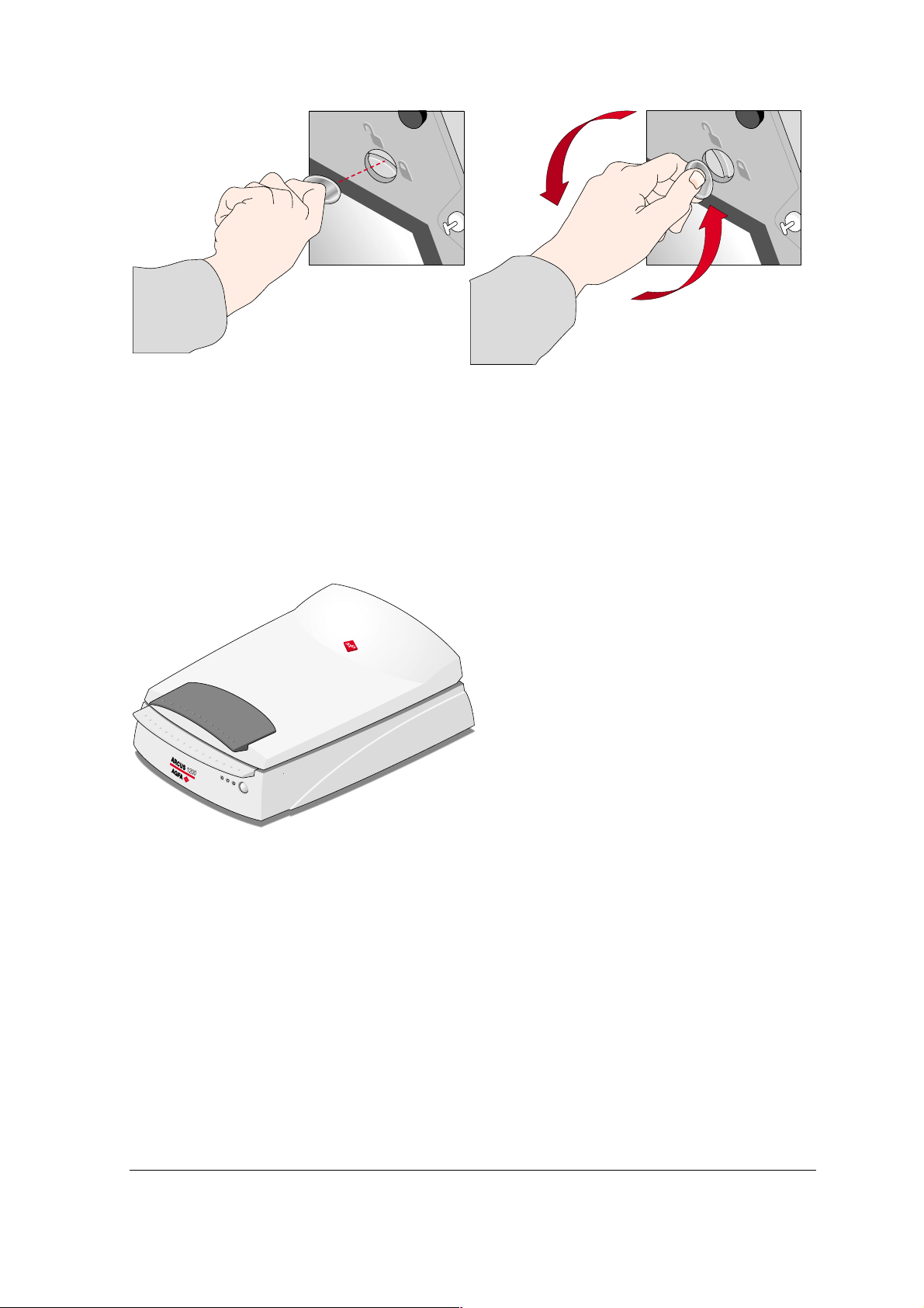
The TPU is unlocked.
Taking a Closer Look
Now that you have taken the scanner out of the box, you can take a closer look, so that you
become familiar with its parts.
Chapter 1: Preparing the Scanner 8
Page 9
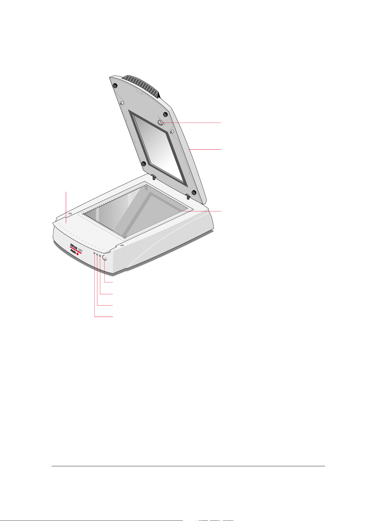
The Different Parts of Your Scanner
The figure illustrates the locations of the different parts of your Arcus 1200.
1
2
4
3
5
6
7
8
1. TPU unlocking screw
2. TPU
3. rulers
4. removable tray (glass plate/batch slide holder frame)
5. stand-by switch
6. power indicator
7. progress indicator
8. indicator for transparency scanning (Tx)
" Note: After 15 minutes of inactivity of the scanner, the scanner switches automatically to
stand-by mode. To switch off your scanner, disconnect the power cord from the wall outlet.
Chapter 1: Preparing the Scanner 9
Page 10
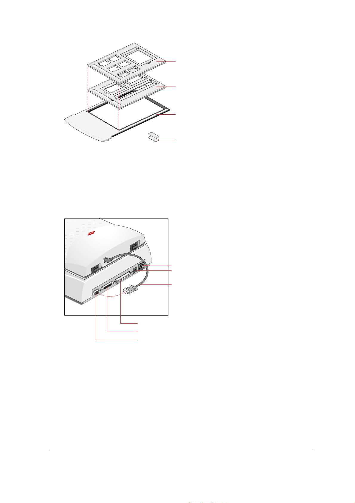
1
2
3
4
1
35 mm framed and 4 x 5 inch batch slide holder
2
35 mm strip and 6 x 9 cm batch slide holder
3
batch slide holder frame
4
small plastic holder to make 6 x 9 cm universal (6 x 7 cm or 6 x 6 cm)
The following figure illustrates the location of the different parts at the rear of your scanner.
1
power input
2
SCSI ID switch
3
TPU-cable
4
50-pin SCSI interface connector
5
25-pin SCSI interface connector
6
TPU connector
1
2
3
4
5
6
Chapter 1: Preparing the Scanner 10
Page 11

Working with Trays and a Flexible Template
Trays
A locking system is installed for safety reasons, to protect the scanner's optical assembly and its
electronic components from possible damage and dust.
Two trays are delivered with your scanner:
1. glass plate
The TPU will automatically be locked, when you remove the glass plate from your scanner.
" Note: When you have inserted the glass plate in the scanner, you can open the TPU again.
When the batch slide holder frame is in the scanner, the TPU will be locked.
2. batch slide holder frame
The TPU is open:
you cannot remove
the glass plate,
because it is locked.
The TPU is closed:
you can remove the
glass plate. The TPU
cannot be opened,
because it is locked.
Flexible Template
To use the flexible template, you have to open the TPU. When the TPU is open, you can position
the flexible template on the glass plate.
" Note: If you have removed the glass plate, the TPU will automatically be locked. Make sure
you have inserted the glass plate in the scanner, before trying to open the TPU.
" Note: The flexible template ensures that your original does not cover the calibration area. If
you do not use the template, make sure to leave a space of 4 cm between the front ruler and
your original.
Chapter 1: Preparing the Scanner 11
Page 12

Connecting the Transparency Unit (TPU)
To scan negatives, transparencies or slides you have to use the TPU on your Arcus 1200:
•
Connect the TPU cable to your scanner as shown in the figure below.
Chapter 1: Preparing the Scanner 12
Page 13

Chapter 2: Installing the Scanner
This chapter shows you how to set up your Arcus 1200 with your Apple Macintosh or Windows PC.
You will find information about:
!
Minimum Hardware and Software Requirements
!
Environmental Requirements
!
Precautions
!
Cleaning Your Scanner
!
SCSI Devices
!
Installation for Mac OS
!
Installation of the Software
!
Which SCSI Interface Card
!
Choosing a SCSI ID Number
!
Connecting the Scanner
!
Testing the Scanner and the Connection
!
Installation for Windows
!
Installation of the Software
!
Which SCSI Interface Card
!
Choosing a SCSI ID Number
!
Connecting the Scanner
!
Testing the Scanner and the Connection
Chapter 2: Installing the Scanner 13
Page 14

Minimum Hardware and Software Requirements
# For the Apple Macintosh:
$
A Power Macintosh™
$
32 MB of RAM if virtual memory is switched on, 64 MB RAM if virtual memory is switched
off
$
A 17 inch color monitor (24 bit color display recommended)
$
System™ 8.1 or Mac OS 9 operating system
$
A CD-ROM drive
$
SCSI interface
$
40 MB of free disk space on the start-up disk
# For the Windows PC:
$
A Pentium processor or higher
$
A 15 inch color monitor
$
A video card for an accurate display of color images (minimum thousands of colors)
$
32 MB of RAM (64 MB of RAM is recommended)
$
FotoLook is compatible with all IBM™ PC's and compatibles capable of running Windows
95, Windows 98, Windows NT 4.0 or Windows 2000 for Intel platforms.
$
An ASPI™ compatible SCSI card. In general, FotoLook supports all fully WINASPI
compatible cards. Some SCSI cards require a special SCSI cable (for example wide
SCSI). Contact your supplier for the proper cable.
" Note: Please read the installation and set-up guidelines in the documentation that is
supplied together with your SCSI interface card. In case of problems, consult the Owner’s
Guide Arcus 1200 on the Agfa Scanners CD-ROM.
$
A CD-ROM drive
$
The amount of disk space available on your PC determines the number and size of the
images you can scan. Make sure you have enough free storage space on your hard disk.
You need about two times the size of the image to scan, edit and save an image. You
need a minimum of 30 MB free hard disk space.
" Note: Check your CD-ROM cover or Read Me file for the latest information on hardware
requirements.
Chapter 2: Installing the Scanner 14
Page 15

Environmental Requirements
# Place the scanner on a horizontal, flat surface.
# To ensure proper ventilation, allow a minimum of 10 cm (4 inches) free space around each
side of the scanner and a minimum of 15 cm (6 inches) at the rear of the scanner.
# Make sure that no vibrations or shocks occur.
# Make sure that the area is free of excessive dust.
# Avoid any contact with water.
# The scanner is designed to operate optimally when the environmental temperature is between
10°C and 35°C (50 °F to 95 °F). Avoid exposure to direct sunlight and heating devices.
# The scanner is designed to operate optimally when the environmental humidity is between
10% and 85%. Avoid environments where humidity fluctuations might occur.
# Check whether the voltage of the power supply corresponds to the voltage of your scanner. If
not, contact your dealer or Agfa service representative.
Precautions
For your own safety and that of your equipment, respect conscientiously the Environmental
Requirements and always take the following precautions:
Caution
guide, do not try to remove any mechanical parts or any electronic devices. If your scanner needs
service, our dealer and service offices are available to help you.
# Handle your Arcus 1200 with care: its glass plate is fragile. There is no warranty on breaking
# Check frequently whether there is no overheating of the power plug and whether the power
# Switch the machine to stand-by mode at the end of your working day or during power failure.
# Disconnect the power plug when you want to clean the reflective glass plate and when the
# Do not open the scanner housing as it contains high-voltage areas and sensitive components.
# Do not leave originals in the scanner for excessive periods of time. The warmth of the scanner
# Make sure to attach transparent originals on the glass plate with the flexible template and with
: For the reason of safety, besides the personal maintenance mentioned in this owner's
the glass plate and your dealer is not liable for the consequential damages.
plug is pushed all the way into the wall outlet.
scanner needs service.
Any curative maintenance should be carried out by your dealer or Agfa service representative.
may cause them to deteriorate.
adhesive tape. Otherwise you might loose them in the scanner.
# To avoid crashes, never use extension cables for SCSI cables.
# For safety reasons, never use extension cables for power cables.
Chapter 2: Installing the Scanner 15
Page 16

Cleaning Your Scanner
# In order to maintain the quality of your scanned images, regularly clean the glass plate.
# Before cleaning, switch off the scanner by unplugging the power cord.
# Use a damp cloth and a mild detergent or alcohol to clean the surface of the glass plate.
# When you use sprays directly onto the glass plate, avoid the seams around the glass, as this
may cause the liquid to penetrate and contaminate the mirrors and lenses inside the scanner.
Do not use detergent on the plastic parts of your scanner.
# Especially the cleaning of the calibration slits in the holders is important. Keep this area dust-
and dirt-free.
SCSI Devices
Arcus 1200 is a Small Computer System Interface (SCSI) device. It communicates with your
computer by using the SCSI-2 standard. The SCSI communication standard allows you to have
several peripheral devices connected to your computer.
Before connecting the SCSI devices you should always make sure that your computer and all SCSI
devices are switched off. If either the computer or any of the devices remains on, you could
damage the computer or the device.
A unique SCSI ID number is assigned to each device in the SCSI chain enabling your computer to
identify the device it wants to communicate with and the priority of each device.
Caution
you may damage your SCSI devices. To avoid crashes, never use extension cables for SCSI
cables.
: If two SCSI devices have the same ID number, your system will not work properly and
Installation for Mac OS
This section shows you how to set up your Arcus 1200 with your Macintosh computer. You must
first install the software after which you have to choose and set a SCSI ID number, then connect
the scanner to your Macintosh, and finally test the scanner and the connection.
Installation of the Software
Please consult the Getting Started manual.
" Note: Before installing the scanner software, you have to install the image editing software
(ReadIris™ and Corel™).
Chapter 2: Installing the Scanner 16
Page 17

Which SCSI Interface Card
Arcus 1200 requires a SCSI interface to work with your Macintosh. If your Macintosh does not have
a SCSI interface card or built-in interface, contact your dealer.
Adaptec™ products are recommended to use together with your Arcus 1200.
" Note: If you use an external SCSI-card, consult the documentation supplied with your interface
card. This will tell you how to install the card.
Choosing a SCSI ID Number
Before you connect your Arcus 1200 to your Macintosh, you have to find out which SCSI ID
numbers are already assigned and which numbers are free. You can find the SCSI ID Checker in
the Utilities folder inside the Agfa FotoLook folder after you have installed the software. You can
use the SCSI ID Checker to verify if your scanner is part of your SCSI chain. Here you can also find
out which SCSI ID numbers are already assigned and which numbers are free.
1
Double-click the SCSI ID Checker icon.
A dialog box appears with a list of the SCSI ID numbers in your Macintosh computer.
Your Macintosh always occupies ID 7, its internal hard disk usually occupies ID 0 or ID 1 and
CD ROM usually occupies ID 3. If your Macintosh is equipped with 2 SCSI-busses, the button
Next Bus allows you to switch busses.
2
Check if SCSI ID number 2 is free.
Your Arcus 1200 is preset to ID 2.
3
If SCSI ID number 2 is free, go to instruction 4.
Chapter 2: Installing the Scanner 17
Page 18

-or-
If SCSI ID number 2 is already assigned, you need to set the scanner to a free SCSI ID
number.
$
Make sure that your scanner is switched off.
$
Decide on an unassigned SCSI ID number.
$
Use the SCSI ID switch at the rear of the scanner to set the desired SCSI ID:
$
Press – to decrease the SCSI ID number.
-or-
Press + to increase the SCSI ID number.
4
Click OK to close the SCSI ID Checker.
Connecting the Scanner
Before you connect the scanner to your Macintosh, make sure that your scanner as well as your
Macintosh and everything connected to it are switched off.
A terminator and a SCSI cable are supplied with your scanner.
Caution
there is no more than one terminator in your SCSI chain and that it is placed at the end of the
chain. Some SCSI devices have built-in terminators and must therefore be placed at the end of
your SCSI chain. Please check the documentation of each of your SCSI devices if you are not sure
whether the device has a built-in terminator or not. Your Arcus 1200 has no built-in terminator.
: For safety reasons, never use extension cables for power cords. Always make sure that
Chapter 2: Installing the Scanner 18
Page 19

If your Arcus 1200 is the only external SCSI device to be connected to your Apple Macintosh:
1
Place the terminator on the 50-pin connector of the scanner.
2
Snap the diamond shaped wire clips into the clip brackets to secure the connection.
3
Connect the 50-pin end of the SCSI cable to the free side of the terminator.
4
Snap the diamond shaped wire clips into the clip brackets to secure the connection.
5
Connect the smaller 25-pin end of the SCSI cable to the connector of your Apple Macintosh.
6
Tighten the connector screws to secure the connection.
Chapter 2: Installing the Scanner 19
Page 20

If your Arcus 1200 will be connected to your Apple Macintosh together with other external SCSI devices:
If you install the scanner at the end of your SCSI chain
1
Remove or switch off the terminator from the last device in the SCSI chain.
2
Connect the 50-pin end of the SCSI cable to the connector that has become available on this
device.
3
Snap the diamond shaped wire clips into the clip brackets to secure the connection.
4
Connect the 25-pin end of the SCSI cable to the 25-pin connector of the scanner.
5
Tighten the connector screws to secure the connection.
6
Place the terminator on the 50-pin connector of the scanner.
Chapter 2: Installing the Scanner 20
Page 21

If your scanner is the first external device of your SCSI chain
1
Connect the 50-pin end of the SCSI cable to the connector of the next device in the SCSI
chain.
2
Snap the diamond shaped wire clips into the clip brackets to secure the connection.
3
Connect the 25-pin end of the SCSI cable to the connector of the scanner.
4
Tighten the connector screws to secure the connection.
5
Make sure that the last device in the SCSI chain is terminated.
Chapter 2: Installing the Scanner 21
Page 22

If you install the scanner between two other external SCSI devices
1
Disconnect the SCSI cable from one of these two SCSI devices.
2
Connect the free end of this SCSI cable to the scanner.
3
Connect the 50-pin end of the SCSI cable (the one supplied with your scanner) to the other
adjacent SCSI device.
4
Snap the diamond shaped wire clips into the clip brackets to secure the connection.
5
Connect the 25-pin end of the SCSI cable (the one supplied with your scanner) to the scanner.
6
Tighten the connector screws to secure the connection.
7
Make sure that the last device in the chain is terminated.
Chapter 2: Installing the Scanner 22
Page 23

Testing the Scanner and the Connection
You are now ready to check if the scanner is operating properly and if the devices are correctly
connected to your Macintosh.
Caution
1
2
3
4
5
6
: Check if the scanner is properly unlocked.
Connect the power cord to the scanner.
" Note: Make sure that you are using the correct power cord for the voltage in your area.
Double-check whether the voltage indicated on the back panel of the scanner
corresponds with the voltage in your area. If not, contact your dealer or Agfa service
representative.
Check if the SCSI cable is properly connected.
Switch on the scanner.
" Note: While starting up the scanner, the power indicator (green) switches on after which
the progress indicator switches on. The scanner performs a self-test for about 25
seconds. At the end of the self-test, the progress indicator will automatically go out if
there are no problems. If a malfunction is detected during the self-test, that is, if the
progress indicator remains blinking, consult Appendix A: Troubleshooting.
Switch on any other SCSI device you may have attached, and wait for it to start up.
Switch on your Macintosh.
As it starts up, your Macintosh performs a series of tests to verify the correct system
configuration.
Open the SCSI ID Checker.
7
Verify whether the Macintosh sees the scanner at its proper SCSI address.
In case of problems, consult Appendix A: Troubleshooting.
8
Close the SCSI ID Checker.
Chapter 2: Installing the Scanner 23
Page 24

Installation for Windows
This section shows you how to set up your Arcus 1200 with your Windows PC. You can find
information on which SCSI interface card to use, instructions for connecting the scanner to your PC
and instructions for testing the scanner and the connection.
Installation of the Software
Please consult the Getting Started manual.
" Note: Before installing the scanner software, you have to install the FotoLook Scanner Driver.
Which SCSI Interface Card
Arcus 1200 requires a SCSI interface card to work with your PC or compatible computer. If your PC
does not have such a card or built-in interface, contact your dealer.
Adaptec products are recommended to use together with your Arcus 1200.
" Note: Please check the following documentation:
$
The Read Me file on the PC scanner driver software disk for up-to-date information.
$
The documentation supplied with your interface card. This will tell you how to install the
card.
Choosing a SCSI ID Number
Before you connect your Arcus 1200 to your PC, you have to find out which SCSI ID numbers are
already assigned and which numbers are free. To do this, you can use a Windows utility that is
usually bundled with your SCSI interface card.
1
Open the SCSI ID utility supplied with your SCSI interface card.
Your PC SCSI card mostly occupies ID 7.
" Note: For more information consult the SCSI interface card documentation.
2
Check if SCSI ID 2 is free.
Your Arcus 1200 is preset to ID 2.
3
If SCSI ID 2 is free, go to instruction 4.
-or-
If SCSI ID number 2 is already assigned, you need to set the scanner to a free SCSI ID
number.
Chapter 2: Installing the Scanner 24
Page 25

$
Make sure that your scanner is switched off and that it is disconnected from your
computer.
$
To decrease the SCSI ID number: push -.
$
To increase the SCSI ID number: push +.
4
Close the SCSI ID utility.
Connecting the Scanner
Before you connect the scanner to your PC, make sure that your scanner as well as your PC and
everything connected to it are switched off.
" Note: Before connecting the scanner to your PC, you have to install the scanner software.
A terminator and a SCSI cable are supplied with your scanner.
Caution
there are no more than two terminators in your SCSI chain, one at the beginning and one at the
end. Some SCSI devices have built-in terminators and must therefore be placed at the beginning or
end of your SCSI chain. Please check the documentation of each of your SCSI devices if you are
not sure whether the device has a built-in terminator. Your Arcus 1200 has no built-in terminator.
Never try to connect the scanner to the serial or parallel port of your PC: you might seriously
damage your equipment if you do.
If your PC has a high density connector:
# You might need to buy a specific SCSI cable from your dealer.
: For safety reasons, never use extension cables for power cords. Always make sure that
Chapter 2: Installing the Scanner 25
Page 26

If your PC has a 25-pin connector and your Arcus 1200 is the only external SCSI device to be connected to your PC:
" Note: If your configuration also consists of internal SCSI devices and if your SCSI controller
does not disable termination automatically, do not forget to disable the termination of the host
adapter. Consult your computer documentation for more information.
1
Set the scanner to an unused SCSI ID number between 0 and 6.
For more information, consult Choosing a SCSI ID Number.
2
Connect the smaller 25-pin end of the SCSI cable to the connector of your PC.
3
Tighten the connector screws to secure the connection.
4
Place the terminator on the 50-pin connector of the scanner.
5
Snap the diamond shaped wire clips into the clip brackets to secure the connection.
6
Connect the larger 50-pin end of the SCSI cable to the free side of the terminator. Use the
SCSI cable supplied with the scanner.
7
Snap the diamond shaped wire clips into the clip brackets to secure the connection.
Chapter 2: Installing the Scanner 26
Page 27

If your PC has a 25-pin connector and your Arcus 1200 will be connected to your PC together with other external SCSI devices:
If you install the scanner at the end of your SCSI chain:
1
Set the scanner to an unused SCSI ID number between 0 and 6.
For more information, consult Choosing a SCSI ID Number.
2
Remove or switch off the terminator from the last device in the SCSI chain.
3
Connect the 50-pin end of the SCSI cable to the connector that has become available on this
device.
4
Snap the diamond shaped wire clips into the clip brackets to secure the connection.
5
Place the terminator on the 50-pin connector of the scanner.
6
Snap the diamond shaped wire clips into the clip brackets to secure the connection.
7
Connect the 25-pin end of the SCSI cable to the connector of the scanner.
8
Tighten the connector screws to secure the connection.
Chapter 2: Installing the Scanner 27
Page 28

If your scanner is the first external device of your SCSI chain
1
Set the scanner to an unused SCSI ID number between 0 and 6.
For more information, consult Choosing a SCSI ID Number.
2
Connect the 50-pin end of the SCSI cable to the connector of the next device in the SCSI
chain.
3
Snap the diamond shaped wire clips into the clip brackets to secure the connection.
4
Connect the 25-pin end of the SCSI cable to the connector of the scanner.
5
Tighten the connector screws to secure the connection.
6
Make sure that the last device in the chain is terminated.
Chapter 2: Installing the Scanner 28
Page 29

If you install the scanner between two other external SCSI devices
1
Set the scanner to an unused SCSI ID number between 0 and 6.
For more information, see Choosing a SCSI ID Number.
2
Disconnect your SCSI cable from one of these two SCSI devices.
3
Connect the free end of this SCSI cable to the scanner.
4
Connect the 50-pin end of the SCSI cable (the one supplied with your scanner) to the other
adjacent SCSI device.
5
Snap the diamond shaped wire clips into the clip brackets to secure the connection.
6
Connect the 25-pin end of the SCSI cable (the one supplied with your scanner) to the scanner.
7
Tighten the connector screws to secure the connection.
8
Make sure that the last device in the chain is terminated.
Chapter 2: Installing the Scanner 29
Page 30

If your PC has a 50-pin connector and your Arcus 1200 is the only external SCSI device to be connected to your PC:
" Note: If your configuration also consists of internal SCSI devices and if your SCSI controller
does not disable termination automatically, do not forget to disable the termination of the host
adapter. Consult your computer documentation for more information.
1
Set the scanner to an unused SCSI ID number between 0 and 6.
For more information, see Choosing a SCSI ID Number.
2
Connect the larger 50-pin end of the SCSI cable to the connector at the rear of your PC. Use
the SCSI cable supplied with the scanner.
3
Snap the diamond shaped wire clips into the clip brackets to secure the connection.
4
Place the terminator on the 50-pin connector of the scanner.
5
Snap the diamond shaped wire clips into the clip brackets to secure the connection.
6
Connect the smaller 25-pin end of the SCSI cable to the connector of the scanner.
7
Tighten the connector screws to secure the connection.
Chapter 2: Installing the Scanner 30
Page 31

If your PC has a 50-pin connector and your Arcus 1200 will be connected to your PC together with other external SCSI devices:
If you install the scanner at the end of your SCSI chain
1
Set the scanner to an unused SCSI ID number between 0 and 6.
For more information, see Choosing a SCSI ID Number.
2
Remove or switch off the terminator from the last device in the SCSI chain.
3
Connect the 50-pin end of the SCSI cable to the connector that has become available on this
device.
4
Snap the diamond shaped wire clips into the clip brackets to secure the connection.
5
Place the terminator on the 50-pin connector of the scanner.
6
Snap the diamond shaped wire clips into the clip brackets to secure the connection.
7
Connect the 25-pin end of the SCSI cable to the connector of the scanner.
8
Tighten the connector screws to secure the connection.
Chapter 2: Installing the Scanner 31
Page 32

If your scanner is the first external device of your SCSI chain
1
Set the scanner to an unused SCSI ID number between 0 and 6.
For more information, see Choosing a SCSI ID Number.
2
Connect the 25-pin end of the SCSI cable to the connector of the next device in the SCSI
chain.
" Note: If you do not have the appropriate cable, contact your dealer for a specific cable.
3
Tighten the connector screws to secure the connection.
4
Connect the 50-pin end of the SCSI cable to the connector of the scanner.
5
Snap the diamond shaped wire clips into the clip brackets to secure the connection.
6
Make sure that the last device in the chain is terminated.
Chapter 2: Installing the Scanner 32
Page 33

If you install the scanner between two other external SCSI devices
1
Set the scanner to an unused SCSI ID number between 0 and 6.
For more information, see Choosing a SCSI ID Number.
2
Disconnect the SCSI cable from one of these two SCSI devices.
3
Connect the free end of this SCSI cable to the scanner.
4
Connect the 50-pin end of the SCSI cable (the one supplied with your scanner) to the other
adjacent SCSI device.
5
Snap the diamond shaped wire clips into the clip brackets to secure the connection.
6
Connect the 25-pin end of the SCSI cable (the one supplied with your scanner) to the scanner.
7
Tighten the connector screws to secure the connection.
8
Make sure that the last device in the chain is terminated.
Caution
In case of problems, consult Appendix A: Troubleshooting.
: In this configuration you are not allowed to put the terminator on the scanner.
Testing the Scanner and the Connection
You are now ready to check if the scanner is operating properly and if the devices are correctly
connected to your PC.
Caution
1
: Check if the scanner is properly unlocked.
Connect the power cord to the scanner.
Chapter 2: Installing the Scanner 33
Page 34

" Note: Make sure that you are using the correct power cord for the voltage in your area.
Double-check whether the voltage indicated on the back panel of the scanner
corresponds with the voltage in your area. If not, contact your dealer or Agfa service
representative.
2
Check if the SCSI cable is properly connected.
3
Switch on the scanner.
" Note: While starting up the scanner, the power indicator (green) switches on after which
the progress indicator switches on. The scanner performs a self-test for about 25
seconds. At the end of the self-test, the progress indicator will automatically go out if
there are no problems. If a malfunction is detected during the self-test, that is, if the
progress indicator remains blinking, consult Appendix A: Troubleshooting.
4
Switch on any other SCSI device you may have attached, and wait for it to start up.
5
Switch on your PC.
6
Windows will detect the scanner.
Chapter 2: Installing the Scanner 34
Page 35

Chapter 3: Placing Originals
This chapter shows you how to scan with your Arcus 1200.
!
Changing Removable Trays
!
Placing Reflective Originals
!
Placing Transparent Originals
!
Using the Glass Plate and the Flexible Template
!
Using the Batch Slide Holders
Chapter 3: Placing Originals 35
Page 36

Changing Removable Trays
Your Arcus 1200 contains a removable glass plate as well as a removable batch slide holder
frame. This paragraph explains how to remove this glass plate.
" Note: The batch slide holder frame, which you can use to scan transparencies, can be
removed in the same way.
1
Close the TPU.
2
Remove the glass plate as shown in the figure below.
Caution
holder frame.
: Make sure the TPU is closed, before you try to remove the glass plate or the batch slide
Placing Reflective Originals
You place a reflective original, such as a photograph, directly on the scanner's glass plate. The
Arcus 1200 has an adjustable TPU: when you scan a thick original (like a book or a magazine) on
the reflective glass plate, the TPU adjusts automatically to the thickness of the original. If
necessary, you can remove the TPU completely.
1
Open the TPU of the scanner.
" Note: Make sure the glass plate is inserted, otherwise the TPU is locked.
2
Place the original face down on the glass plate with the top side against the front ruler.
Chapter 3: Placing Originals 36
Page 37

" Note: Optical performance of a CCD scanner is always best near the middle of the scan
area. However, the specified scan quality is guaranteed for the entire scan area.
3
Close the TPU of the scanner.
" Note: The removable TPU makes it possible to scan from books and magazines. When you
put a thick original on the reflective glass plate, the TPU adjusts automatically to the thickness
of the original.
If necessary, you can remove the TPU completely by lifting it. Before removing the TPU you
have to disconnect the TPU cable. After replacing the TPU, do not forget to reconnect the TPU
cable.
Chapter 3: Placing Originals 37
Page 38

Placing Transparent Originals
When you scan transparent originals, there are two possibilities:
# You can use the glass plate and the flexible template;
# You can use the batch slide holders. The batch slide holders fit into the batch slide holder
frame which you insert in the scanner.
Using the Glass Plate and the Flexible Template
To scan a transparent original, carry out the following instructions:
1
Open the TPU of your scanner.
" Note: Make sure the glass plate is inserted, otherwise the TPU is locked.
2
Place the flexible template on the glass plate.
3
Center the original on the template so that its top side is directed towards the calibration slit.
" Note: Make sure that the calibration slit of the flexible template is at the front side and that it is
clean.
Using the Batch Slide Holders
The batch slide holders are available in order to increase the productivity of the scanner. The
concept of the batch slide holders is developed so that a variety of combinations are possible.
The base is the batch slide holder frame in which different kinds of batch slide holders can be
mounted. The batch slide holders keep the originals perfectly flat between two plastic frames, thus
guaranteeing optimum sharpness.
1
Put your original face down in the appropriate batch slide holder.
Chapter 3: Placing Originals 38
Page 39

2
Put the batch slide holder with the originals in the batch slide holder frame with the Agfa logo
at the top.
3
Insert the batch slide holder frame in the scanner.
" Note: Before you put the batch slide holder frame in your scanner, close the TPU and
remove the glass plate from the scanner.
1.
35 mm framed and 4 x 5 inch batch slide holder
2.
35 mm strip and 6 x 9cm batch slide holder
3.
batch slide holder frame
4.
small plastic holder to make 6 x 9 cm universal (6 x 7 cm or 6 x 6 cm)
35 mm framed (6) and 4 x 5 inch (1) batch slide holder
This holder can hold a maximum of 7 slides at the time. Once loaded it is mounted into the batch
slide holder frame.
1
Put your original face down in the 35 mm framed or 4 x 5 inch batch slide holder.
2
Put the batch slide holder into the batch slide holder frame with the Agfa logo at the top.
3
Put the batch slide holder frame into the scanner.
Chapter 3: Placing Originals 39
Page 40

35 mm strip (1) and 6 x 9 cm (2) batch slide holder
S
R
Q
P
Z
One strip of maximum 6 negatives and 2 slides can be mounted into the holder which is then
mounted into the batch slide holder frame.
1
Put your strip with the originals or your slides face down in the batch slide holder.
P Q R S Z
2
Close the lid and slide it sideways.
Your originals are correctly positioned for scanning.
3
Put the batch slide holder into the batch slide holder frame with the Agfa logo at the top.
4
Put the batch slide holder frame into the scanner.
Chapter 3: Placing Originals 40
Page 41

Appendix A: Troubleshooting
This appendix explains some common problems you may come across when starting up or using
your Arcus 1200.
The power indicator fails to light up.
# Verify the power connection to the scanner.
If you have confirmed that there is power to the scanner it is likely that the scanner fuse needs
to be replaced. Contact your dealer.
The power indicator lights up but nothing happens.
# Contact your dealer or Agfa service representative.
The scanner makes a loud knocking noise and the optical carriage does not move under the glass plate.
The scanner contains an autolock system in the form of a foot at the bottom of your scanner to
protect the scanner’s optical assembly from possible damage and dust.
# The scanner was not properly unlocked. Immediately switch off the scanner and unlock
properly by placing the scanner on a flat surface, or call your service representative.
" Note: The TPU of your scanner is locked when you pull the scanner out of the box. Please
consult the Getting Started Manual for information about unlocking the TPU.
The progress indicator light on the scanner's operating panel remains blinking after the power-up sequence (= about 25 seconds).
A malfunction has been detected by the scanner.
# Check if you have unlocked the scanner. If this cannot be the problem please contact your
dealer or Agfa service representative.
The workstation does not start up. If your workstation is an Apple Macintosh a little floppy disk with a question mark appears on your screen.
Your workstation cannot find its hard disk due to a conflict with the SCSI ID numbers of the devices
you have attached.
# Disconnect all SCSI devices (except the start-up disk) and connect them one by one,
beginning with the scanner, to identify the device that causes the problem (switch off all
devices before breaking or making connections).
Appendix A: Troubleshooting 41
Page 42

The scanner software cannot find the scanner.
After opening the Scan dialog box, a message appears telling that no scanner is connected,
although the scanner is connected.
# Check the Installation procedure, to see if you followed the instructions. Pay special attention
to the setting of the SCSI ID number.
# Maybe you did not wait long enough for all SCSI devices to start up, before you switched on
your workstation. Therefore, try restarting your workstation.
# Disconnect all SCSI devices and connect them one by one, beginning with the scanner, to
identify the device that causes the problem.
# Make sure that your devices have different SCSI numbers. If there are devices with the same
number, assign a different number to each device.
Your original fell into the scanner.
# Contact your dealer or Agfa representative.
An error message appears while you scan transparencies.
# Use the flexible template to make sure that your original does not cover the calibration area. If
you do not use the template, make sure to leave a space of 5 cm between the front ruler and
your original.
The TPU is not working.
# Make sure the TPU cable is properly attached to your scanner:
1 Switch off your scanner by disconnecting the power cord from the wall outlet.
2 Attach the TPU cable to your scanner.
3 Connect the power cord to the wall outlet.
# Check if the TPU indicator starts blinking while starting up your scanner.
The TPU cannot be opened.
The TPU will automatically be locked, when you have removed the glass plate from your scanner
or when the batch slide holder frame is in the scanner. This locking system is installed for safety
reasons to protect the scanner’s optical assembly from possible damage and dust.
# Make sure you have inserted the glass plate, before trying to open the TPU.
The TPU option is not selectable in the software.
# Make sure the TPU cable is properly attached to your scanner, then push the stand-by switch
to make the TPU option available in the software.
.
Appendix A: Troubleshooting 42
Page 43

Appendix B: Technical Information
This appendix provides some technical information about your Arcus 1200. Technical specifications
are subject to change without notice.
Scanner type:
CCD:
Optical resolution
Output resolution
A/D conversion
Output pixel depth:
Density range:
Scanning speed:
:
Flatbed color CCD scanner
10,600 elements, color type
:
:
2,400 ppi vertical x 1,200 ppi horizontal
20 – 4,800 ppi
36 bit (12 bit per color)
1 bit output for line-art (black and white)
8 or 12 bit output for gray
24 or 36 bit output for color
Reflection: 0 to 2 D
Transmission: 0 to 3.2 D
Speed mode:
Reflective: line-art/grayscale/color:
<10 ms/line
Transparent: line-art/grayscale/color:
<10 ms/line
Quality mode:
Reflective: line-art/grayscale/color:
<20 ms/line
Transparent: line-art/grayscale/color:
<20 ms/line
Preview speed A4 color 10 s
Scanning area:
Memory:
Reflection Scanner lamp:
Transparency lamp:
Original sizes:
A4 or Legal
Maximum reflective:
216 x 297 mm (8.5 '' x 11.7 '')
Maximum transparency:
203 x 254 mm (8” x 10 “)
2 MB RAM
Cold cathode
6,000 hr lifetime
Cold cathode
6,000 hr lifetime
Appendix B: Technical Information 43
Page 44

Lamp warm up time:
Approximately 15 seconds
180 seconds to reach final image quality
Power supply:
Power consumption:
100 V to 240 V, 47-63 Hz
<35 W
Dimensions:
- length: 555 mm
- width: 386 mm
- height: 187 mm
- weight: 10 kg
Acoustic noise:
Interface:
Max. 50dB in worst condition
SCSI-2 interface
Maximum throughput 2.5 MB/sec
Environment:
Operating temperature:
10°C to 35°C (50 °F to 95 °F)
Relative humidity:
20% to 85%
Appendix B: Technical Information 44
Page 45

Appendix C: Arcus 1200 Regulation Compliance
!
Safety Regulations
!
Electromagnetic Compatibility
Appendix C: Arcus 1200 Regulation Compliance 45
Page 46

Safety Regulations
Arcus 1200 has been designed to comply with:
# VDE 0805
# IEC 950, EN 60950 (GS approved)
# UL 1950-D3
# CSA c22.2 No. 950-M89
Arcus 1200 also complies with CE regulations and carries the CE mark.
UL Safety Statement
Instructions for power supply cord selection:
Use a UL listed, Type SVT or SJT cord, three conductor, rated 10 A 125 V, not to exceed 15ft in
length.
TÜV: Wichtige Sicherheitshinweise
# Bitte Lesen Sie sich diese Hinweise sorgfältig durch.
# Um eine Beschädigung des Gerätes zu vermeiden sollten Sie nur Zuberhörteile verwenden,
die vom Hersteller zugelassen sind.
# Das Gerät ist vor Feuchtigkeit zu schützen.
# Bei der Aufstellung des Gerätes ist auf sicheren Stand zu achten. Ein Kippen oder Fallen
könnte Verletzungen hervorrufen. Verwenden Sie nur sichere Standorte und beachten Sie die
Aufstellhinweise des Herstellers.
# Die Belüftungsöffnungen dienen zur Luftzirkulation die das Gerät vor Überhitzung schützen.
Sorgen Sie dafür, daß diese Öffnungen nicht abgedeckt werden.
# Die Netzanschlußsteckdose mußaus Gründen der elektrischen Sicherheit einen
Schutzleiterkontakt haben.
# Durch die Lüftungsöffnungen dürfen niemals Gegenstände oder Flüssigkeiten in das Gerät
gelangen. Dies könnte einen Brand bzw. elektrischen Schlag auslösen.
# Öffnen Sie niemals das Gerät. Das Gerät darf aus Gründen der elektrischen Sicherheit nur
von authorisiertem Servicepersonal geöffnet werden.
# Die Steckdose sollte nahe dem Gerät und leicht zugänglich sein.
Appendix C: Arcus 1200 Regulation Compliance 46
Page 47

Electromagnetic Compatibility
Arcus 1200 is designed to comply with:
# Emission: EN55022, Class B
# Immunity: IEC 801-2; IEC801-3; IEC 801-4
# FCC Document 20718, part 15, subpart B, class B
Federal Communications Commission Radio Frequency Interference Statement.
This equipment has been tested and found to comply with the limits for a Class B digital device,
pursuant to Part 15 of the FCC rules. These limits are designed to provide reasonable protection
against harmful interference when the equipment is operated in a residential installation. This
equipment generates, uses, and can radiate radio frequency energy and, if not installed and used
in accordance with the instruction, manual may cause harmful interference to radio
communications. However, there is no guarantee that interference will not occur in a particular
installation. If this equipment does cause harmful interference to radio or television reception, which
can be determined by turning the equipment off and on, the user is encouraged to try to correct the
interference by one or more of the following measures:
# Reorient or relocate the receiving antenna,
# Increase the separation between the equipment and receiver,
# Connect the equipment into an outlet on a circuit different from that to which the receiver is
connected,
# Consult the dealer or an experienced radio/television technician for help.
Canadian Department of Communications
This Class B digital apparatus meets all the requirements of the Canadian Interference Causing
Equipment Regulations.
Cet appareil numérique de la classe B respecte touts les exigences du Règlement sur le matériel
brouilleur du Canada.
Appendix C: Arcus 1200 Regulation Compliance 47
 Loading...