

Page 1
OPERATING MANUAL
(Original operating manual)
Automatic Pallet Loader APL-106
Agfa NV
Septestraat 27
B-2640 Mortsel
Telephone +32 3 444 2111
Internet www.agfagraphics.com
Please keep this manual for future use!
Page 2

Machine / machine line: Automatic Pallet Loader APL 106A / Agfa Expert Loader
Year of construction:
Manufacturer:
2018 following
Krause-Biagosch GmbH, Paul-Schwarze-Str.5, D-33649
Bielefeld
Version 06
Revision: March 2019
Document history
Version Date Reason for Change Editor Status
3 July 2017 First edition Richter released
4
November 2018
Cassette Loader and Extension
Modul added
Richter released
Agfa name change to Agfa NV
Chapter 5, Installation and Setup
changed,maintanance extended
to the cassette loader,
maintenance materials silicon
spray, cleaning agent and
grease
5
February 2019
Pallet and plate data more
detiled.Cassette safety (5,12),
Richter released
extension module and cassette
operation (44,46ff)
6
r1
March 2019
April 2019
Corrected version numbers.
Maintenance instructions for
cassettes, note for safety
stickers added.
Maintenance intervals changed
Ahlemeyer released
© Agfa NV
This operating manual and all illustrations contained herein are protected by copyright. Any
use beyond the constraints of copyright law without the prior written consent of the publisher
is illegal and punishable by law. This particularly applies to copying, translation, transfer to
microfilm, and saving and processing in electronic systems.
Page 3

Table of Contents
1 Introduction ............................................................................................................ 1
1.1 Means of representation .......................................................................................... 2
1.2 Warranty and liability ............................................................................................... 3
1.3 Copyright ................................................................................................................. 4
1.4 Terms of guarantee ................................................................................................. 4
1.5 Service / customer service ....................................................................................... 4
2 Safety ...................................................................................................................... 5
2.1 Intended use ............................................................................................................ 5
2.1.1 Constructional modifications to the machine ............................................................ 6
2.1.2 Foreseeable misuse ................................................................................................ 7
2.2 Personnel requirements ........................................................................................... 8
2.2.1 Obligations of the personnel .................................................................................... 9
2.2.2 Unauthorised persons .............................................................................................. 9
2.2.3 Instruction ................................................................................................................ 9
2.3 General safety information ..................................................................................... 10
2.4 Safety measures for environmental protection ....................................................... 10
2.5 Special hazard warnings ........................................................................................ 11
2.5.1 Symbols used on the machine ............................................................................... 11
2.5.2 Safty sticker on the machine .................................................................................. 12
2.5.3 Hazards due to electrical energy ............................................................................ 13
2.5.4 Hazards due to pneumatic energy ......................................................................... 13
2.6 Personal protective equipment .............................................................................. 14
2.7 Information for emergencies .................................................................................. 15
3 Machine description ............................................................................................ 17
3.1 Machine overview .................................................................................................. 17
3.2 Function and operating elements ........................................................................... 18
3.3 Operating panel ..................................................................................................... 19
3.4 Function description ............................................................................................... 20
3.5 Safety device ......................................................................................................... 22
3.5.1 MAIN SWITCH and EMERGENCY STOP. ............................................................ 22
3.5.2 Contact switches on the doors and hoods ............................................................. 22
3.6 Type plate .............................................................................................................. 23
4 Transport and installation site ............................................................................ 25
4.1 Transport ............................................................................................................... 25
4.1.1 Inspection on handover to the customer ................................................................ 25
4.1.2 Scope of delivery ................................................................................................... 25
4.1.3 Information regarding hazards during transport ..................................................... 26
Permissible auxiliary equipment for transport ......................................................... 27
4.1.4
Automatic Pallet Loader APL /Expert Loader I
Page 4

Table of Contents
4.1.5 Dimensions and weights of the packages .............................................................. 27
4.1.6 Recommended transport equipment ...................................................................... 28
4.1.7 Intermediate storage .............................................................................................. 28
4.1.8 Transport packing .................................................................................................. 28
4.2 Installation site ....................................................................................................... 29
4.2.1 Load-bearing capacity of the installation surface .................................................... 29
4.2.2 Flatness of the installation surface ......................................................................... 29
4.2.3 Safety lighting ........................................................................................................ 29
4.2.4 Air conditioning ...................................................................................................... 29
4.2.5 Regulation of the humidity ..................................................................................... 30
5 Installation and commissioning/first start-up .................................................... 31
6 Operation .............................................................................................................. 33
6.1 Switching on the machine ...................................................................................... 33
6.2 Emptying the paper bin .......................................................................................... 34
6.3 Loading a pallet ..................................................................................................... 37
6.4 Loading a machine with 2nd pallet space............................................................... 44
6.5 Removing a pallet .................................................................................................. 45
6.6 Loading plates to the cassettes (optional) .............................................................. 46
6.7 Removing faulty printing plates .............................................................................. 47
6.8 Switching off the machine ...................................................................................... 48
7 Malfunctions......................................................................................................... 49
7.1 Display of malfunction messages ........................................................................... 49
7.1.1 System error .......................................................................................................... 50
7.1.2 Warnings ............................................................................................................... 50
7.1.3 Sequence error ...................................................................................................... 52
8 Maintenance and cleaning .................................................................................. 53
8.1 Maintenance intervals and maintenance work........................................................ 54
8.2 Cleaning agents and lubricants .............................................................................. 56
9 De-commissioning ............................................................................................... 57
10 Dismantling .......................................................................................................... 59
10.1 Information regarding hazards during dismantling .................................................. 59
10.2 Preparatory measures ........................................................................................... 60
10.3 Dismantling the machine and securing it for transport ............................................ 60
10.3.1 Preparing and securing the machine for transport .................................................. 61
10.3.2 Supply lines ........................................................................................................... 65
10.3.3 Paper bin ............................................................................................................... 66
11 Disposal ................................................................................................................ 67
11.1 Terminology ........................................................................................................... 67
II
Page 5

Table of Contents
11.2
Overview of the assembly groups .......................................................................... 68
12 Appendix .............................................................................................................. 71
12.1 Technical data ....................................................................................................... 71
12.1.1 Dimensions ............................................................................................................ 71
12.1.2 Weights ................................................................................................................. 72
12.1.3 Electrical connected loads/rating ........................................................................... 72
12.1.4 Compressed air connected values/capacity ........................................................... 72
12.1.5 Ambient conditions ................................................................................................ 73
12.1.6 Airborne noise emitted ........................................................................................... 73
12.1.7 Heat emission ........................................................................................................ 73
12.1.8 Printing plate and pallet sizes ................................................................................ 74
12.2 Other applicable documents .................................................................................. 75
12.3 EC Declaration of Conformity ................................................................................ 75
Automatic Pallet Loader APL / Expert Loader III
Page 6

Page 7

1 Introduction
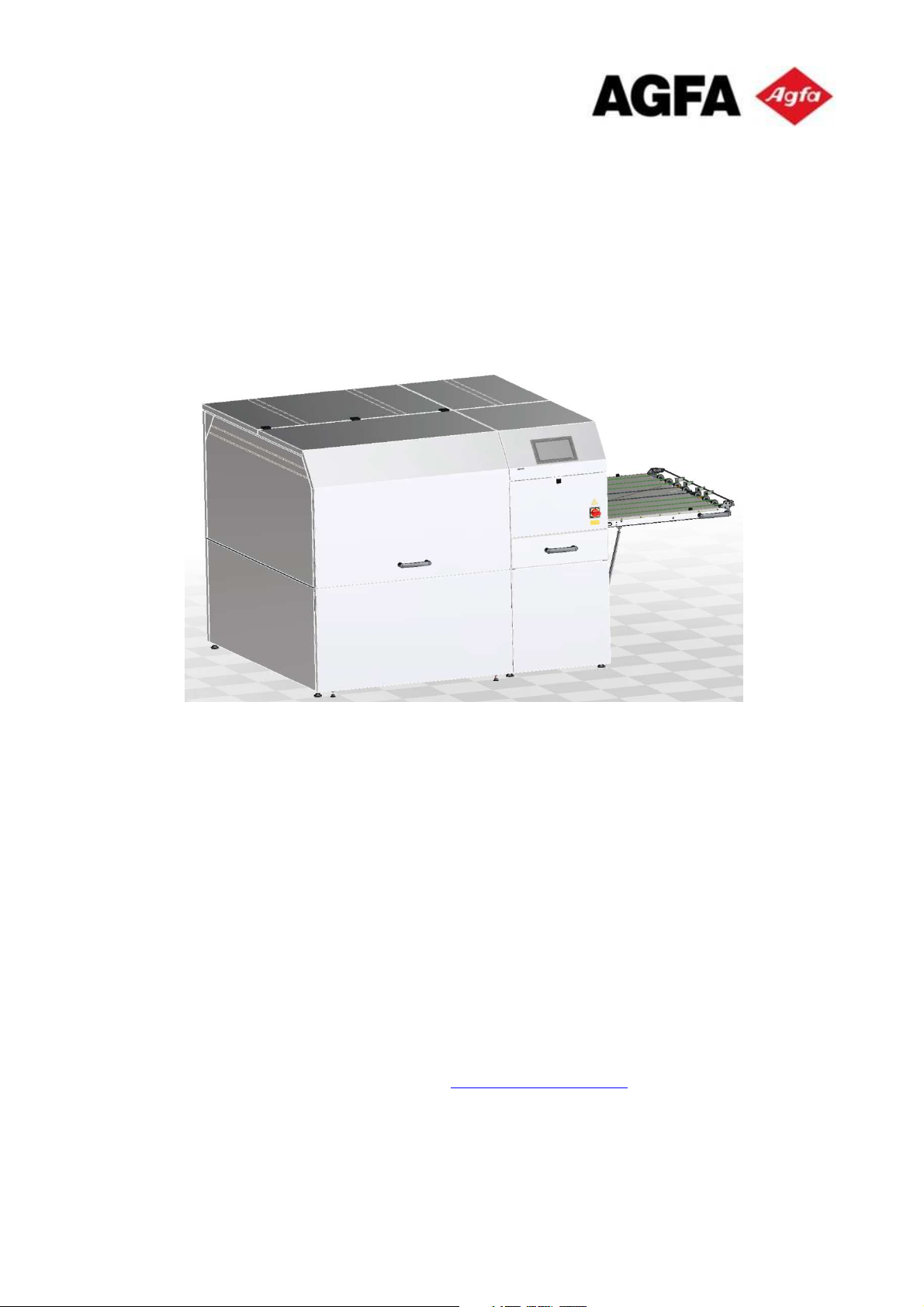
This operating manual provides you with all the information required for problemfree operation of the Automatic Pallet Loader APL-106 /Expert Loader (referred to
as "machine" hereinafter).
The function of the machine is to separate, align and convey printing plates to the
downstream machine line module "Recorder".
This operating manual must be read, understood and applied by all persons
instructed to carry out the
–
transport,
–
installation and assembly,
–
first start-up/commissioning,
–
operation,
–
maintenance and cleaning,
–
malfunction remedy,
–
de-commissioning and dismantling
–
and disposal
of the machine. This applies in particular to the specified safety instructions.
Studying the operating manual will enable you to correctly
–
install,
–
connect,
–
operate,
–
maintain
–
and dispose of the machine.
Observe the regulations generally valid by law and other binding regulations
regarding accident prevention and environmental protection of the country of use
in addition to this operating manual.
Automatic Pallet Loader APL / Expert Loader 1
Page 8

1.1 Means of representation
Statements in this installation manual intended as information on and direct
warning of hazards are identified as follows:
DANGER
This warning describes a hazard with a high degree of risk, which if
WARNING
not avoided, will lead to death or serious injury.
This warning describes a hazard with a medium degree of risk,
which if not avoided, may lead to death or serious injury.
1 Int roduction
CAUTION
This warning describes a hazard with a low degree of risk, which if
not avoided, may lead to minor or moderate injury.
NO TE
This warning describes a hazard with a low degree of risk, which if
Furthermore, the following text features are used:
– Dashes precede list items.
•
Bullets precede instructions describing actions that are to be carried out in
the specified order.
Text in inverted commas refers to other chapters or sections.
" "
Text in square brackets describes touch buttons to be pressed on the
[ ]
operating panel.
not avoided, may lead to damage to assets.
The information symbol marks useful information.
2
Page 9

1.2 Warranty and liability
Danger to life due to electric shock
Warning: suspended load
Symbols used in this manual
Particular hazards are additionally marked in warnings as follows:
This symbol warns of the life-threatening hazard of electrical current.
Contact with live components causes imminent danger to life.
This symbol warns of the hazards of standing/working under
suspended loads.
1.2 Warranty and liability
The obligations agreed to in the delivery contract, the General Terms and
Conditions, as well as the machine delivery terms and the legal regulations valid
at the time of the conclusion of the contract apply.
All the information and instructions in this operating manual were compiled taking
the valid standards and regulations, state of the art and our many years of
experience and expertise into consideration.
Warranty and liability claims on the basis of personal injury and damage to assets
are excluded if they can be traced back to one or several of the following causes:
–
Improper use or use other than that intended of the machine;
–
incorrect installation, assembly, operation, maintenance, cleaning,
disassembly;
–
non-observance of the operating manual and information in the operating
manual regarding installation, assembly, operation, maintenance, cleaning,
disassembly, disposal;
–
use of insufficiently qualified or insufficiently instructed/trained personnel;
–
structural changes to the machine (no conversions or any other changes to
the machine may be performed without the prior written consent of Agfa
NV. Any infringement will result in loss of the machine's EC conformity);
–
incorrectly carried out repairs;
–
use of non-approved spare parts and/or use of spare parts that do not meet
the technical requirements;
–
events of catastrophe caused by foreign objects and force majeure.
We reserve all rights to make technical changes within the framework of
improvement of the performance characteristics and further development.
Automatic Pallet Loader APL / Expert Loader 3
Page 10

1.3 Copyright
This operating manual is protected by copyright and is exclusively intended for
internal purposes.
1 Int roduction
Handing over the operating manual to third parties, making copies of any kind
including excerpts – as well as using and/or disclosing the contents are prohibited
unless expressly consented to in writing by Agfa NV, except for internal
purposes.
Any infringement will result in liability for damages. We reserve the right to assert
further claims.
1.4 Terms of guarantee
The terms of guarantee are contained in the General Business Terms of
Agfa NV.
1.5 Service / customer service
In the event of problems please contact the representative in charge.
–
4
Page 11

Non
-
observance of the fo
llowing safety information may have
ion to the instructions contained in this operating manual, the
user/owner must adhere to the existing national work, operating and
2 Safety
WARNING
serious consequences:
– Danger to persons resulting from electrical, pneumatic or
mechanical influences;
– failure of important machine functions.
Thoroughly read all the safety and warning information in this
section before commencing with the transport, installation,
connection and commissioning/start-up of this machine.
In addition to the instructions contained in this operating manual,
also observe the universally valid safety and accident prevention
regulations.
In addit
safety regulations. Also adhere to the existing internal works
regulations.
2.1 Intended use
The operational safety of the machine is only guaranteed if it is used in
accordance with its intended use.
The machine is exclusively intended for automatically loading printing plates into
the downstream machine line module "Recorder".
The machine is not intended for any use other than that specified here, any other
use is deemed as non-intended use. The following is forbidden in particular:
–
To transport persons with the machine;
–
to convey products other than those specified;
–
to convey products with different weights than those specified.
The intended use also includes:
–
Using energy supplies in accordance with the valid safety regulations;
–
adhering to the specified operating conditions.
–
adhering to the inspection and maintenance intervals;
Automatic Pallet Loader APL / Expert Loader 5
Page 12

–
using consumables and auxiliary substances in accordance with the valid
safety regulations;
–
adhering to the specified operating conditions.
The technical specifications specified in the technical data must be adhered to
without exception.
Only use the machine in accordance with its intended use, otherwise safe
operation will not be guaranteed.
The manufacturer declines any responsibility for injuries and damage to
assets resulting from any use other than that intended. The user/owner of
the machine line alone is fully liable in this respect!
2.1.1 Constructional modifications to the machine
2 Saf ety
The design and manufacturer's acceptance are based on the Product Safety Act
(ProdSG). No modifications, attachments to or conversions of the machine may
be carried out without the prior written permission of
Agfa NV.
Non-compliance will result in loss of the machine's EC conformity. The
manufacturer's warranty will become null and void. This also applies to welding
work on load-bearing parts.
Immediately replace components that are not in perfect condition.
Only use original spare parts/wear parts/accessory parts. These parts are
specifically designed for the machine. If non-original parts/parts procured from
other sources are used, it cannot be guaranteed that they are properly designed
and manufactured with regard to stress and safety.
Parts and special equipment not supplied by Agfa NV are not approved for use
on the machine.
6
Page 13

2.1 Intended use
Any addi
tional use and/or type of use of the machine other than
2.1.2 Foreseeable misuse
WARNING
the intended use can lead to serious injuries!
– Only use the machine in accordance with its intended use.
– Only load the machine with the designated printing plates.
Automatic Pallet Loader APL / Expert Loader 7
Page 14

Risk of injury in the event of insufficient qualifications!
2.2 Personnel requirements
WARNING
Incorrect handling can cause serious injuries to persons and
Ensure that the machine is only transported, installed, set up and operated by
personnel specifically qualified and/or instructed to do so. These persons must
be familiar with the operating manual and act accordingly. The respective duties
and responsibilities of the personnel must be clearly defined.
damage to assets.
– Therefore restrict all work to suitably qualified personnel.
2 Saf ety
The following qualifications are specified in the operating manual for various
areas of activity:
Instructed personnel
Instructed personnel have been instructed by the user/owner or by qualified
personnel regarding the tasks to be performed and the possible hazards caused
by incorrect behaviour.
Qualified personnel
Qualified personnel, due to their specialist training, knowledge and experience,
and knowledge of the pertinent regulations, are able to perform the work they are
commissioned with and independently recognize and avoid potential hazards.
Electricians
Electricians, due to their specialist training, knowledge and experience, as well as
knowledge of the pertinent standards and regulations, are able to carry out work
on the electrical equipment and independently recognise and avoid potential
hazards.
Qualified electricians are trained for the specific operating site at which they work,
and are familiar with the relevant standards and regulations pertaining to this site.
8
Page 15

2.2 Personnel requirements
Danger for unauthorised persons!
If in doubt, speak to the unauthorised persons and show them out
Specialist pneumatic personnel
Specialist pneumatic personnel, due to their specialist training, knowledge and
experience are able to monitor and maintain pneumatic equipment and systems.
They can independently recognise and avoid potential hazards.
Specialist pneumatic personnel are trained for the specific operating site at which
they work, and are familiar with the relevant standards and regulations pertaining
to this site.
2.2.1 Obligations of the personnel
Personnel may only include persons who can be expected to carry out their work
reliably. Do not allow persons whose reactions are negatively affected by drugs,
alcohol, medication or similar to work on the machine.
All persons instructed to work on the machine undertake, prior to commencing
work,
–
to observe the basic directives concerning health and safety at work and
accident prevention,
–
to read the safety instructions and the warnings contained in this operating
manual and confirm this with their signature, acknowledging that they have
understood the information.
2.2.2 Unauthorised persons
WARNING
Unauthorised persons who do not meet the requirements described
here with respect to the qualifications are not familiar with the
hazards in the work area.
– Keep unauthorised persons away from the work area.
–
of the work area.
– Interrupt the work while unauthorised persons are in the work
area.
2.2.3 Instruction
The personnel require regular instruction and training by the owner/user. This
instruction and training must be recorded in writing for monitoring purposes.
Automatic Pallet Loader APL / Expert Loader 9
Page 16

2.3 General safety information
–
The machine may only be transported, installed, set up and
commissioned/started up after the personnel have familiarised themselves
with this operating manual.
–
Only use the machine in accordance with its intended use (see section
"2.1 Intended use").
–
Keep the work area of the machine clean and tidy at all times to avoid
hazards caused by dirt and parts lying around.
–
Keep all safety and hazard information/signs on the machine in legible
condition and replace them when necessary.
–
Restrict all work on the machine to qualified or instructed personnel (see
Section "2.2 Personnel requirements").
2 Saf ety
2.4 Safety measures for environmental protection
Adhere to the regulations for waste avoidance and for correct waste recycling
and disposal.
In particular during installation work as well as during decommissioning,
disassembly and disposal ensure that substances hazardous to groundwater
such as grease, oil, solvent-containing cleaning agents or similar do not
contaminate the ground or enter the sewage system. Collect, transport, store and
dispose of these substances in suitable containers in accordance with the
national regulations.
10
Page 17

2.5 Special h azard war nings
Danger to life due to electric shock
Warning: danger of hand injury / crushing hazard
This symbol warns of the danger of eye damage from laser radiation.
2.5 Special hazard warnings
2.5.1 Symbols used on the machine
This symbol warns of the life-threatening hazard of electrical current.
Contact with live components causes imminent danger to life.
This symbol warns of the danger of hand injuries.
Your hands could be crushed, pulled in or otherwise injured.
Warning: danger of eye damage / laser radiation
Laser radiation entering the eye can lead to irreparable damage to
the eye.
Warnung: Maloperation
This symbol warns of danger due to maloperation for example when
loading the cassettes.
Keep all safety and hazard information/signs on the machine in legible
condition and replace them when necessary.
Automatic Pallet Loader APL / Expert Loader 11
Page 18

2.5.2 Safty sticker on the machine
2 Saf ety
Overview
There are safety stickers on the covers of the machine:
A
B
Fig. 2: Safety sticker on the machine
Position Safety Labels meaning
A
Danger to life due to electric
shock.
B
12
Class 1 laser product. No
dangerous laser radiation outside
the machine when all doors and
hatches are shut.
Page 19

2.5 Special h azard war nings
Contact with live parts causes electric shock.
2.5.3 Hazards due to electrical energy
DANGER
– Always keep electrical components enclosed.
– Only allow an electrician who is specifically trained to carry out
work on electrical equipment and who is able to detect and avoid
the hazards involved to perform work on the electrical equipment.
–
Restrict work on the electrical equipment to a designated qualified
electrician, e.g. company electrician.
–
Have the electrical equipment inspected/tested by an electrician before
installation and set-up of the machine.
–
Any changes made following this inspection must comply with
DIN EN 60204-1.
–
Damaged housings/casings and cables must be immediately repaired or
replaced before installation and set-up of the machine.
2.5.4 Hazards due to pneumatic energy
Air escaping at high pressure can penetrate the skin and cause serious injuries!
–
Only allow expert personnel specially trained and experienced in pneumatic
engineering to work on the pneumatic installations. Ensure that the
machine is switched off and secured against reactivation before
commencing work on the pneumatic installations.
–
Inspect all pneumatic lines, hoses and connections for externally visible
damage prior to installation and set-up of the machine.
–
Always keep pneumatic hoses away from your body.
–
Protect open air connections against the ingress of dirt.
–
Never interchange connections, connectors/plugs or switches. This will
inevitably result in malfunctions.
Automatic Pallet Loader APL / Expert Loader 13
Page 20

Protective clothing
fitting sleeves and without protruding parts.
Safety footwear
Protective gloves
2.6 Personal protective equipment
It is necessary to wear personal protective equipment during work on the
machine to minimise hazards to health.
–
Always wear the personal protective equipment required for each type of
work.
–
Always follow the instructions regarding personal protective equipment
affixed in the work area.
These symbols have the following meaning:
Protective clothing consists of tight-fitting work clothing with low
tensile strength, with tightThis mainly serves as protection against being caught by moving
machine parts.
2 Saf ety
Do not wear any rings, necklaces, chains or other jewellery.
Wear slip resistant safety shoes to protect against heavy falling parts
and to prevent slipping on smooth surfaces.
Wear protective gloves to protect your hands from friction, abrasion
or deeper injuries.
Personal protective equipment is to be provided by the owner/user and must
meet the pertinent requirements.
In addition, observe the national regulations and any internal instructions laid
down by the owner/user.
14
Page 21

2.7 Information for emergencies
2.7 Information for emergencies
Preventive measures
–
Be prepared for accidents at any time.
–
Keep the first-aid equipment (first-aid boxes, blankets etc.) ready to hand.
–
Train personnel so that they are familiar with accident reporting and the
first-aid equipment.
–
Keep accesses clear for emergency vehicles.
Measures in the event of accidents
–
Rescue persons from the hazardous area.
–
Immediately administer first aid in the event of cardiac arrest and/or
breathing arrest.
–
In the event of injury/damage to health immediately notify the first-aid
supervisor and an emergency doctor and the emergency rescue service.
–
Clear the accesses for emergency vehicles. Delegate someone to direct
the emergency personnel to the site of the accident if necessary.
Automatic Pallet Loader APL / Expert Loader 15
Page 22

Page 23

5
3 Machine description
3.1 Machine overview
1 Pallet compartment Printing plate intake
2 Paper bin Paper removal and double sheet detector
3 Operating panel Operation and status display
4 Transfer table Transfer to CTP exposure unit
5 Extension module Printing plate intake
Model right
Model left
Automatic Pallet Loader APL / Expert Loader 17
Page 24

6
3.2 Function and operating elements
3 Machine description
1 Door element Access to the pallet compartment and air servicing unit
2 Door element Acess to the paper bin
3 Operating panel Touch panel for operating the machine
4 Main switch ON/OFF switch
5 Folding table Transfer table, can be folded up
6 Cassette compartment
18
Page 25
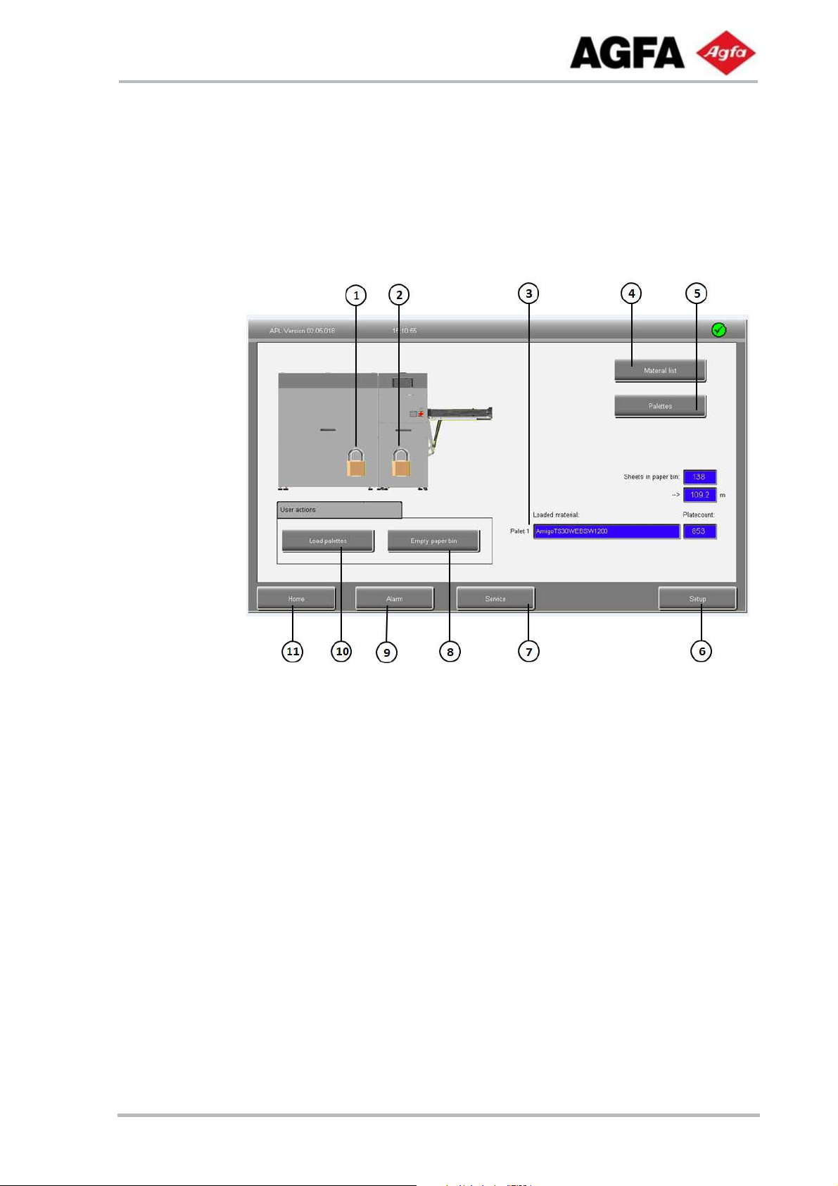
3.3 Operating panel
Display of the alarm list with the malfunctions that
3.3 Operating panel
Main menu
1 Display Locking status (pallet compartment hood)
2 Display Locking status (paper bin door)
3 Display Display of the currently loaded material with the
number of plates remaining
4 [Material list] Display of the material list (material database)
6 [Pallets] Display/change the loaded pallets/materials
6 [Setup] System settings
7 [Service] Settings
8 [Empty paper bin] User prompting for emptying the paper bin
(see section "6.2 Emptying the paper bin")
9 [Alarm]
have occurred
10 [Load pallets] User prompting for loading the pallets
(see section "6.3 Loading a pallet")
11 [Home] Return to main menu
Automatic Pallet Loader APL / Expert Loader 19
Page 26

3.4 Function description
The printing plates are delivered on a pallet which is equipped with a chipboard in
the respective format of the printing plate.
Loading the machine with pallets
One pallet each with printing plates can be placed in the receiving area of the
pallet compartment.
Fixing brackets are fitted to 2 corners of each pallet to prevent the printing plates
from slipping during transport to the receiving area.
A safety belt is supplied for transporting the unpacked printing plates with a lift
truck to prevent sliding of the up to 540 mm high plate stack during the
movement.
Loading the optional cassettes
3 Machine description
The cassettes are an option. The machine can be equipped with one or two
cassettes. Each cassette can carry up to maximum 100 plates of 0,3mm
thickness. The cassettes have movable stoppers adjusted to the required plate
format.
To lode a requested cassette it will be moved downwards by a machine to a
comfortable height before it can be pulled out for loading.
Alignment in the machine
The pallet is deposited with the aid of a lifting device into the receiving area of the
extension module or end module. A marking is located on the floor of the
respective receiving area along which the front edge of the respective pallet must
be aligned.
The position of the printing plate stack (in the transport direction) is indicated with
the aid of a laser marker. The longitudinal edge of the printing plate stack must
be aligned with the laser marking.
Referencing the printing plates
Once the the pallet with the printing plates has been placed in position and
aligned, the respective cover hood is closed.
The feeder – initiated by the downstream machine line module "Recorder"
–
performs a reference run. The position and format of the printing plates are
checked. If they correspond to the set point values, the machine is ready for
operation and the printing plates can be fed to the recorder.
20
Page 27

3.4 Funct ion description
Recorder feeding
The signal for feeding is given by the recorder control system.
The feeder moves over and is lowered onto the respective printing plate stack.
The separating sheet is gripped by the gripping device, pulled back slightly and then
lifted.
The suction device for the printing plate swivels into the suction position and moves
vertically onto the printing plate. The printing plate is lifted with the aid of suction
cups. The support rollers for the transport of the printing plate are extended and the
feeder moves with the printing plate and the gripped separating sheet into the transfer
position.
On reaching the transfer position, the separating sheet is pressed between 2 rubber
rollers with the aid of a pressure roller. The rubber rollers pull in the separating sheet
and convey it into the paper bin. The printing plate is conveyed up to the transfer
position of the loader and taken over by the loader of the recorder.
The loading process is completed. The feeder moves back to the printing plate stack
and picks up the next printing plate.
Automatic Pallet Loader APL / Expert Loader 21
Page 28

3.5 Safety device
The APL-106 is an independent machine. It is switched on using the red and
yellow main switch. The main switch also serves as an EMERGENCY STOP
switch
3.5.1 MAIN SWITCH and EMERGENCY STOP.
Turn the main switch to its horizontal position to disconnect the machine from all
voltage and trigger an EMERGENCY STOP.
To restart the machine, turn the MAIN SWITCH to position 1.
3.5.2 Contact switches on the doors and hoods
3 Machine description
The door to the set-up area of the paper bin in the basic module is equipped with
a door contact switch with guard control.
The cover hoods of the pallet compartment are equipped with contact switches
with guard control.
The door and cover hoods can be released on the operating panel.
1 Contact switch (Cover hood, pallet compartment)
2 Door contact switch (access to paper bin, basic module)
22
Page 29

3.6 T ype plat e
3.6 Type plate
The type plate is located on the rear of the paper bin or on the left-hand side of
the main switch
Automatic Pallet Loader APL / Expert Loader 23
Page 30

Page 31

4 Transport and installation site
4.1 Transport
The machine is delivered to the customer by a transport company authorised by
Agfa NV.
NO TE
It is important that the personnel provided by the owner/user follow
the instructions of the person in charge in order to ensure correct
transport and thus the functional reliability and precision of the
machine.
The persons in charge are named in the order confirmation.
4.1.1 Inspection on handover to the customer
When the component parts of the machine arrive, the customer must inspect
them for visible transport damage and completeness.
–
Document any transport damage before releasing the transport units
(packages).
–
Immediately report any transport damage to Agfa NV.
4.1.2 Scope of delivery
The machine delivery scope comprises the following components:
–
APL 106 with pressure plate transfer module
–
One optional extension module
–
Transfer tables, folded up for transport
–
Paper bin, interior
–
Assembly materials
Automatic Pallet Loader APL / Expert Loader 25
Page 32

Risk of injury due to incorrect handling of the packages!
When transporting the packages, take the following specific hazards
4 Transport and installation site
4.1.3 Information regarding hazards during transport
WARNING
into consideration:
– Protruding edges can cause crushing injuries or cuts.
– Use of load suspension devices other than those specified here
may lead to serious injuries.
NO TE
Handle the packages carefully and take care not to damage the
equipment:
– Lift the packages carefully during transport.
– Do not tilt or twist/distort the packages.
– Ensure that the packages are not subjected to moisture or
extreme temperatures (see section"12.1.5 Ambient conditions").
–
Also read the Chapter "2 Safety".
–
The machine and components may only be unloaded from the freight
forwarder's vehicle by suitably qualified and instructed personnel (forklift
truck operator with certificate of qualification) and in accordance with all
safety regulations.
–
The machine and components may only be transported with a load
suspension device by suitably instructed personnel in accordance with all
safety regulations.
–
Always wear protective clothing, safety footwear and protective gloves
during the work.
–
Ensure that the transport path is secured by an additional person.
–
Ensure that there are no persons on the transport path.
–
Always lift the machine slowly and carefully in order to ensure stability and
safety.
–
Do not remove the transport securing devices (marked red) until the
components have been installed at the installation site.
26
Page 33

4.1 T rans port
Length
4.1.4 Permissible auxiliary equipment for transport
The APL 106 is supplied on a pallet with a crate or in a box (package). These can
be moved using a forklift truck or lift truck.
Ensure that
–
the door widths and load-bearing capacity of the transport paths to the
installation site are sufficient (see section "4.1.5 Dimensions and weights ");
–
the load-bearing capacity of the forklift truck or lift truck is designed for the
weights of the packages (see section "4.1.5 Dimensions and weights ") and
–
the length of the load suspension fork of the forklift truck or lift truck is
sufficiently dimensioned for the packages (see section "4.1.5 Dimensions
and weights “).
The attachment points for secure transport to the installation site are
marked red on the respective packages.
4.1.5 Dimensions and weights of the packages
Package Table of contents
1
APL 106 incl. transfer
table and paper bin
(mm)
2400 2200 2200 685
Width
(mm)
APL 106 with extension
2
modul incl. transfer
3800 2300 2200 910
table and paper bin
* Weight incl. pallet weight (approx. 270 kg)
Interior dimensions of the packaging: 2100 x 2300 x 1900 mm
Height
(mm)
Weight
(kg)
Type
Crate
Crate
Automatic Pallet Loader APL / Expert Loader 27
Page 34

4 Transport and installation site
4.1.6 Recommended transport equipment
Transport equipment
Transport equipment 1
(for unloading the lorry and
lifting the machine off the
pallet)
Transport equipment 2
(for transport of the packages
on the ground)
Transport equipment 3
(for transport of the modules
to the installation site)
4.1.7 Intermediate storage
It the machine is not installed immediately after delivery, the components must be
carefully stored in a protected location. The components must be temporarily
stored such that they are protected from cold temperatures, humidity, dirt and
mechanical influences.
Type
(quantity)
Fork length
(mm)
Perm. loadbearing
capacity (kg)
Forklift truck 2000 3000
2 lift trucks 2000 2000
4 dollies
For the recommended storage conditions for the components please refer to the
section "12.1.5 Ambient conditions".
The manufacturer shall not assume any liability for damage resulting from
incorrect storage.
4.1.8 Transport packing
The machine components are to be unpacked under the supervision of
authorised personnel from Agfa NV.
The packing used for transport and protection of the machine
predominantly consists of recyclable materials.
– Dispose of the packing material in an environmentally friendly manner
in accordance with the applicable country-specific regulations.
28
Page 35

4.2 Installation site
4.2 Installation site
4.2.1 Load-bearing capacity of the installation surface
The load-bearing capacity of the installation surface must be sufficiently
dimensioned such that it can withstand the loads during installation and
production. Also take into consideration short-term point loads during transport by
lift truck and during installation.
Use the weight specifications in the section "4.1.5 Dimensions and weights " as a
basis for calculation.
4.2.2 Flatness of the installation surface
The flatness of the installation surface must meet the following specifications:
Height difference
(mm)
0.5 0.1
4 1
10 4
12 10
4.2.3 Safety lighting
The CTP room should be equipped with safety lighting as defined by the plate
manufacturer.
4.2.4 Air conditioning
over a length of (m)
Agfa NV recommends installing the machine in an air-conditioned room so that
the ambient conditions for the equipment and the materials to be processed can
be kept constant throughout the year
(see section "12.1.5 Ambient conditions").
For the design of the air conditioning system please take into consideration the
thermal output values of the installed devices as defined for the recorder.
Automatic Pallet Loader APL / Expert Loader 29
Page 36

4.2.5 Regulation of the humidity
The relative humidity should remain within defined tolerances. Too high or too
low humidity can have a negative influence on the exposure quality and on the
production stability of the system.
4 Transport and installation site
30
Page 37

The commissioning and first start up is not part of this manual. It shall only
5 Installation and commissioning/first start-up
be done by the quallifed service of Agfa NV.
Please note the restriction to warranty if the installation and setup is not
conducted by the Agfa NV.
Automatic Pallet Loader APL / Expert Loader 31
Page 38

Page 39

Risk of injury in the event of insufficient qualifications!
6 Operation
WARNING
Incorrect operation of the machine can cause serious injuries to
persons and damage to assets.
– Therefore restrict all activities for operating the machine to
suitably qualified personnel.
6.1 Switching on the machine
•
Switch on the higher-ranking machine line module if applicable
(see the "Recorder" operating manual).
•
Switch the machine on at the main
switch (1).
The system controls start up.
Automatic Pallet Loader APL / Expert Loader 33
Page 40

user mask is displayed
The machine carries
6 Ope ration
out a reference run.
The machine is ready
for operation when the
and the green dot at
the top right is visible.
The reference run is started automatically by the Suprasetter. The
APL106 itself starts a reference run after the actions pallet loading and
emptying the paper bin have been completed.
6.2 Emptying the paper bin
•
Touch [Empty paper bin]
(1).
The machine moves into the
safe position (park position).
34
Page 41

6.2 Emptying the paper bin
The door to the set-up area
of the paper bin is unlocked.
•
Open the door to the setup area of the paper bin.
Note: The process can be
aborted by pressing the
button [Cancel].
Display after opening the
door to the set-up area of
the paper bin
Note: If the door is
opened for longer than 10
seconds, the internal
paper counter will be set
to 0.0 m.
• Pull the paper bin (1) out
of the set-up area.
•
Empty the paper bin.
•
Push the paper bin back into the set-up area and close the door. The door is
automatically locked.
The machine has to carry out a reference run.
Automatic Pallet Loader APL / Expert Loader 35
Page 42

the reference run with
Note: If no reference run
seconds, the door will be
The machine carries out a
•
Confirm the start of
6 Ope ration
[OK].
is carried out after 10
unlocked again.
reference run.
•
Confirm the message
with [OK] when the
reference run has
been carried out.
Note: The message
disappears
automatically after 10
seconds.
The machine is then
ready for operation
again.
36
Page 43

6.3 Loading a pallet
6.3 Loading a pallet
A pallet with printing plates can be set up in the set-up area.
Pallet positions
The pallet has to be positioned accurately in the set-up area so that the printing
plate stacks can be detected by the stack detection system. The following figure
shows the area in which the pallet has to be set up.
min:195mm, max:215mm
Ensure that the
spacing between
the pallet stack
and the machine
frame is between
195 and 215 mm.
Left side U- profile
pallet
The laser lines (1)
serve as an
orientation aid for
correct positioning
of the pallet
Automatic Pallet Loader APL / Expert Loader 37
Page 44

6 Ope ration
Loading
The loading of a pallet is described in the following operating steps
•
Touch [Load
pallets] (1).
•
The machine
moves into the
safe position
(home position).
The hoods and the
door are unlocked.
The set-up area of
the machine can
be loaded.
•
Open the hoods.
•
Note: If the hoods are not opened after 30 seconds, they are automatically
locked again and the machine is ready for operation again.
38
Page 45

6.3 Loading a pallet
The pallet is in position
•
Move the pallet with the printing plates into the set-up area with the aid of a lift
truck.
The open and closed
hoods/door are
displayed in the user
mask.
•
Align the pallets such that
–
the front edge of the pallet is flush with the laser marking,
–
the longitudinal edge of the printing plate stack is flush with the second
laser marking.
Result:
The LH securing
brackets (1) remain on
the pallet
Automatic Pallet Loader APL / Expert Loader 39
Page 46

Confirm with [OK] to
6 Ope ration
We recommend that you also empty the paper bin during loading.
The paper bin door is therefore unlocked during loading.
•
Close the hoods and the paper bin door.
For safety reasons it is necessary to acknowledge the locking of the
hoods; the hoods are locked by confirming with [OK].
•
lock the hoods.
The machine has to carry out a reference run and pallet detection.
If no changes to the loading have been made (e.g. if you only
checked the storage compartment) and the set pallet(s)
hasn't(haven't) been moved, pallet detection can be skipped.
40
Page 47

6.3 Loading a pallet
First a reference run is carried
•
If pallets have been
loaded, removed or
moved, start the
detection with [Start
detection] (1).
•
Otherwise detection can
be skipped with [Skip
detection] (2).
out, then it is followed by the
pallet detection if applicable.
Automatic Pallet Loader APL / Expert Loader 41
Page 48

After completion of the
Following the reference
6 Ope ration
run, the stack detection is
active and the position of
the pallets with the printing
plate stacks is detected.
reference run and stack
detection, the allocation
of the pallet(s) in the setup area has to be
checked .
•
Touch [OK] to display
the operating mask
with the printing plate
parameters.
• Check the
allocation and
number of
loaded printing
plates in the
set-up area.
•
If you have
made any
changes, touch
[Apply
changes] after
completion of
the inspection.
42
Page 49

6.3 Loading a pallet
• To complete the
loading process
touch [OK].
Note: The
message
disappears
automatically after
10 seconds.
The machine is
then ready for
operation again.
The machine is ready for production. The machine receives the control
commands from the higher ranking machine line module "Recorder".
Automatic Pallet Loader APL / Expert Loader 43
Page 50

ed in
position another laser line
.
6.4 Loading a machine with 2nd pallet space
•
The machine with 2
pallets spaces (extension
module, EXT) is load
the same way as
described in chapter
Kapitel 6.3.
•
Start from the main
window with “Load pallet”
6 Ope ration
•
For the second pallet
mounted optionally.
•
The machine measures
both positions in any
case and displays the
found pallets and plates.
44
NO TE
The machine is stopped bevor loading and moves to a safe position
The second pallet cannot be loaded during production.
Page 51

6.5 R emoving a pallet
6.5 Removing a pallet
Once the last printing plate has been removed from the feeder, a message
appears on the operating panel Pallet Loader.
•
Start a loading sequence as described in section "6.3 Loading a pallet".
•
First remove the empty pallet and then load a new pallet with printing plates
into the set-up area (see section "6.3 Loading a pallet").
Also unscrew the holder for the
securing bracket (1) from the
empty pallet before disposing of
the pallet!
Also unscrew the rear retaining
brackets from the empty pallet
and fit them to the new pallet!
Automatic Pallet Loader APL / Expert Loader 45
Page 52

Caution
Make sure
is locked !
6.6 Loading plates to the cassettes (optional)
•
If the machine is equipped with
one or two cassettes these are
loaded in a similar procedure as
the pallet loading
•
In the main window press „load
cassettes)
6 Ope ration
•
Follow the instructions on the
screen step by step
•
The cassette moves downwards
to the loading position.
•
Unlock the cassette with the pushbutton at the handle and pull it out
for loading the plates.
•
The maximal loading of one
cassette is 100 plates of 0,3mm
thickness.
•
Make sure the cassette is locked
correctly after loading and
inserting.
that
the cassette
46
Page 53

6.7 R emoving fault y printing plates
6.7 Removing faulty printing plates
Faulty printing plates or printing plates with paper or cardboard are transported to
the transfer table. Then the machine stops with the prompt to remove the plate
from the transfer table.
Afterwards, restart the machine with Start.
Automatic Pallet Loader APL / Expert Loader 47
Page 54

6.8 Switching off the machine
•
6 Ope ration
Switch the machine off at the main
switch (1).
48
Page 55

Danger to life due to electrical voltage!
Risk of injury due to stored p
neumatic energy
Unexpected movements of the machine due to the release of stored
7 Malfunctions
DANGER
Contact with live parts causes electric shock, which can lead to
serious injuries or even death.
– Always turn off the main switch and secure it against being
switched on again prior to accessing the inside of the
machine/reaching into the machine.
CAUTION
energy can lead to moderately severe injuries.
– Always depressurise the machine prior to carrying out any work
on the pneumatics when there is a malfunction in the pneumatic
system.
Always adhere to the local safety regulations when remedying
malfunctions.
This chapter explains how to localise and remedy malfunctions and faults/errors.
Troubleshooting is assisted by the display of error numbers and error
descriptions in the operating mask.
7.1 Display of malfunction messages
If a malfunction message occurs, an alarm message window appears on the
operating panel with the following information regarding the occurred malfunction:
–
Type of malfunction:
–
System error
–
Warning
–
Sequence error
–
Error number
–
Error message
Automatic Pallet Loader APL / Expert Loader 49
Page 56

7.1.1 System error
Error number Error message
8200 No compressed air
8201 Motor 1 (X axis): no communication
8202 Motor 2 (Z axis): No communication
8203 Motor 3 (roller 2):no communication
8204 Motor 4 (roller 4):no communication
8205 Motor 5 (roller rotation):no communication
8206 Suction cup adjustment (Y axis): no pulse
8207 Suction cup adjustment (Y axis): Positioning time-out
8208 Suction cup adjustment (Y axis): Reference time-out
7 Malfunction s
8209 Flaps not closed
8210 Flaps not locked
8211 Flap locking error
8212 Paper bin door not closed
8213 Paper bin door not locked
8214 Motor voltage switched off
7.1.2 Warnings
Error number Error message
8301 Motor 1 (X axis): No reference
8302 Motor 2 (Z axis): No reference
8303 Motor 3 (roller 2): No reference
8304 Motor 4 (roller 4): No reference
8305 Motor 5 (roller rotation): No reference
8306 Suction cup adjustment (Y axis): No reference
8307 Paper bin door open
8308 Segment 1 door open
8309 Paper bin not in position
8310 Stack height cannot be calculated
50
Page 57

7.1 Displ ay of malfunction messages
Error number Error message
8311 No paper before gripping
8312 Paper detected during suction
8313 Motor 1 (X axis): Excessive temperature
8314 Motor 1 (X axis): Overcurrent
8315 Motor 1 (X axis): Undervoltage
8316 Motor 1 (X axis): Overvoltage
8317 Motor 2 (Z axis): Excessive temperature
8318 Motor 2 (Z axis): Overcurrent
8319 Motor 2 (Z axis): Undervoltage
8320 Motor 2 (Z axis): Overvoltage
8321 Motor 3 (roller 2): Excessive temperature
8322 Motor 3 (roller 2): Overcurrent
8323 Motor 3 (roller 2): Undervoltage
8324 Motor 3 (roller 2): Overvoltage
8325 Motor 4 (roller 4): Excessive temperature
8326 Motor 4 (roller 4): Overcurrent
8327 Motor 4 (roller 4): Undervoltage
8328 Motor 4 (roller 4): Overvoltage
8329 Motor 5 (roller rotation): Excessive temperature
8330 Motor 5 (roller rotation): Overcurrent
8331 Motor 5 (roller rotation): Undervoltage
8332 Motor 5 (roller rotation): Overvoltage
Automatic Pallet Loader APL / Expert Loader 51
Page 58

7.1.3 Sequence error
Error number Error message
8230 Double plate or paper detected 3 times
8231 Outfeed: no plate detected
8232 Paper jam in the paper pull-in
8233 Plate in the outfeed during initialisation
8234 Double plate or paper in the outfeed during initialisation
8235 Paper removal failed 3 times
8236 Double plate/paper during transfer
8237 Vacuum fault during plate pick-up
8238 Vacuum lost during plate pick-up
7 Malfunction s
8239 Plate not pulled in by Recorder
8240 Cardboard detected 3 times in a row
8241 Plate on the rollers during initialisation
52
Page 59

Danger to life due to electrical voltage!
Risk of injury due to stored pneumatic energy
tored
Risk of injury due to bursting pneumatic hoses
8 Maintenance and cleaning
DANGER
Contact with live parts causes electric shock, which can lead to
serious injuries or even death.
– Always turn off the main switch and secure it against being
switched on again prior to accessing the inside of the
machine/reaching into the machine.
– Restrict maintenance work on the machine to suitably qualified
personnel.
CAUTION
Unexpected movements of the machine due to the release of s
energy can lead to moderately severe injuries.
– Always depressurise the machine prior to carrying out any
maintenance work on the pneumatics.
CAUTION
Pneumatic hoses with an expired service life may burst and cause
slight or moderately severe injuries.
Proper maintenance and cleaning are crucial for the operational safety and long
service life of the machine. For this reason it is particularly important
– Check the condition of the pneumatic hoses at regular intervals
and replace them if visible wear is detected.
– Do not reuse old pneumatic hoses.
– Only use original spare parts.
–
to precisely adhere to the maintenance intervals;
–
to observe the maintenance chapters of the supplier's documentation.
Complying with the intended use includes adhering to the maintenance intervals
specified in the following.
Automatic Pallet Loader APL / Expert Loader 53
Page 60

8 Maintenance and cleaning
8.1 Maintenance intervals and maintenance work
Duties and
responsibilities
Custom
er
Assembly group
Maintenance
interval
Maintenance work
Service
Entire machine Every 6 months
Guide rails:
Every 6 months
– Feeder
– Extension and
end module
Guide rails:
Every 6 months
– Feeder / support
rollers
Optical sensors on
the feeder (paper
Every 6 months or
as required
detection, plate
edge):
– 4 light barrier
sensors
– Laser sensor
Ultrasonic sensors
at the outfeed slot
Every 6 months or
as required
to the Recorder.
– Clean the work area
– Clean and oil the slide rails.
– Spray the slide rails, in which
the support rollers run, with
silicone spray.
– Clean sensors with a soft lint-
free cloth.
– Clean sensors with a soft lint-
free cloth.
X
X
X
X
X
Feeder drive belts Every 6 months
– Check the drive belts for
X
damage.
Suction cups,
feeder
Every 6 months
– Check the suction cups for
damage (tears and
X
deformation).
Rubber rollers,
basic module
Pneumatic system
of the entire
machine
Every 6 months
Every 6 months
– Check the rubber rollers for
damage.
– Check the pneumatic system
for leaks.
– Check the pneumatic hoses
X
X
for damage.
– Check the condensate level
in the air servicing unit.
54
Page 61

8.1 M aintenan ce interv als and maintenance w ork
Assembly group
Maintenance
interval
Maintenance work
Duties and
responsibilities
Custom
Service
er
Cassette system
Chains
Cassette system,
Guiding rails and
carriages
Every 6 month
Every 12 months
Carefully clean the chain with
an greased tissue. Make sure
that now grease or oil can
sparkle around and damage
the printing plates
The carriages have grease
inside.
Grease the rails carefully
x
X
Automatic Pallet Loader APL / Expert Loader 55
Page 62

8.2 Cleaning agents and lubricants
NO TE
Risk of damage to the machine!
The machine can be damaged by the use of incorrect cleaning
Agfa NV recommends the following cleaning agents and lubricants:
Use Application Product
agents and lubricants.
Only use the recommended cleaning agents and lubricants.
8 Maintenance and cleaning
Cleaning agent Entire machine
Water/soapy water together with a
micro fiber cloth
Lubricant Guide rails Silicone spray
For example Caramba 619902
Silicon spray
Lubricating grease Cassette chain,
x-axis rails
Grease, for example Klüber
CentroPlex 2EP
56
Page 63

Danger to life due to electr
ic shock!
Risk of injury during work on the pneumatic system if it is
9 De-commissioning
DANGER
Danger to life when working on the electrical installation.
– Work on the electrical installation must be restricted to a qualified
electrician.
CAUTION
carried out by insufficiently qualified personnel!
There is a risk of injury during de-commissioning and dismantling
work on the pneumatic system for insufficiently qualified personnel.
– Only allow qualified expert personnel to carry out work on the
pneumatics.
•
Switch off the machine
(see figure in section "3.2 Function and operating elements ").
•
Switch off the downstream machine line module (see operating manual of the
higher ranking machine).
•
Have the supply energies (electricity, compressed air) disconnected by the
respective expert personnel.
•
Disconnect all supply lines from the machine.
Automatic Pallet Loader APL / Expert Loader 57
Page 64

Page 65

When dismantling the machine co
mponent parts, take the
Lifting of the component parts using attachment points not designed
for this purpose can lead to the component parts falling and causing
10 Dismantling
10.1 Information regarding hazards during dismantling
WARNING
following specific hazards into consideration:
injury.
– Only lift the component parts at the specified attachment points
marked red.
NO TE
If the transport securing devices and stabilising elements are not
attached, this can lead to the component parts falling and causing
injury.
– Fit the transport securing devices and stabilising elements before
dismantling the component parts.
Incorrectly dismantled lines/cables can be damaged and cause
smouldering fires and cable fires when reused.
– Restrict all work on the electrical installation to a qualified
electrician.
Incorrectly dismantled pressure lines and connections can be
damaged, causing injuries when reused.
– Restrict all work on the pneumatics to specialist pneumatic
personnel.
As a general rule:
– Wear your personal protective equipment for all work.
Unsuitable dismantling tools can cause damage to the component
parts.
– Use suitable tools only.
– Restrict all work to suitably trained and instructed personnel and
respective expert personnel.
Automatic Pallet Loader APL / Expert Loader 59
Page 66

10.2 Preparatory measures
Prior to dismantling the machine ensure that
–
the machine has been de-commissioned (properly shut down and
disconnected)
(see section "9 De-commissioning");
–
the necessary tools for dismantling are provided;
–
the necessary transport securing devices are provided;
–
the transport equipment is provided
(see section "4.1.6 Recommended transport equipment");
–
additional light sources (hand lamps) are provided for dismantling;
–
the floor area at the site is clean and dust-free to ensure problem-free
transport of the component parts.
10 Di smantling
10.3 Dismantling the machine and securing it for
transport
To prepare the machine for transport, proceed in the following order.
1. Preparing and securing the machine for transport
2. Supply lines
3. Paper bin
4. Package
60
Page 67

10.3 Dismantling the machine and securing it for transport
Moving the machine to its
unit is approximately below the
Movi
ng the transfer table down
10.3.1 Preparing and securing the machine for transport
transport position
• Lifting unit down (1)
• Z axis up to just before the
stop (2)
• x axis right until the extraction
line lasers (3)
• Move the transfer table down
Automatic Pallet Loader APL / Expert Loader 61
Page 68

Moving the transfer table down
Securing the z axis, part 1
10 Di smantling
•
Turn out the screws marked in
green
•
Have two persons hold the
table
•
Turn out the screws marked in
red,
•
Move the table and fasten on
both sides
•
using the screws marked in
green
Moving down and securing the
suction gripping unit
•
Use cable ties to secure the
lifting unit against turning and
moving up on both sides
•
Undo the framework pate on
the z axis (4 screws) (1)
•
Push the framework plate up to
the stop (2)
•
Tighten the screws on the
framework plate (3)
•
The hook of the feeder then
makes contact with the
framework plate (4)
62
Page 69

10.3 Dismantling the machine and securing it for transport
Securing the z axis, part 2
Place a foam plate between the
•
feeder and the cladding (1)
•
In addition, use a belt to
secure the feeder.
Guide the belt through two
openings in the cladding
crossbar (2).
Automatic Pallet Loader APL / Expert Loader 63
Page 70

Securing the z axis cylinder
Securing the x axis
10 Di smantling
•
Prevent the large z cylinder
from extending by securing it
with cable ties.
•
If the cylinder extends during
transport while the
feeder is secured in the top
position, the white timing belt
will come loose and lose its
position.
•
Use a bracket to secure the xz
unit (1).
•
The bracket is screwed to the
cladding and to the
perpendicular aluminium profile
of the x-z unit. The screw on
the cladding is used for this
purpose.
64
Page 71

10.3 Dismantling the machine and securing it for transport
Attaching transport bars
Two transport bars are used for
Cassette securing
•
transport with a lift truck. (1)
and (2)
The cassettes are secured
vertically with a wooden bar
between the cassette and the
paper trolley.
10.3.2 Supply lines
The cables for the voltage supply and the signal cables are routed in cable ducts
and in an energy chain.
•
•
•
Automatic Pallet Loader APL / Expert Loader 65
Disconnect the cables from the connections and pull them out of the cable
ducts.
Remove the energy chain.
Remove the compressed air hoses.
Page 72

Paper bin
Securing the hood
10.3.3 Paper bin
10 Di smantling
•
Open the door to the basic
module and pull the paper bin
out of the basic module.
•
Remove the paper bin
•
and screw it to the plywood
board (1)
(2).
•
Use one flat bar (1) each to
secure the hood on the feet.
66
Securing the paper bin door
•
Once everything is screwed to
the pallet, wrap the machine in
stretch film.
•
This also secures the paper bin
door (1)
.
Page 73

Hazards to health due to incorrect disposal of the machine!
e assembly groups and machine components
11 Disposal
CAUTION
The machine contains pollutants.
– Hand the assembly groups and machine components over to a
– Do not dispose of th
– Adhere to the national regulations.
recognised disposal company.
via the domestic waste system.
Addresses of recognised disposal companies can be obtained from the
environmental agency or responsible authorities.
The information is based on our current knowledge and experience. It
does not release the disposal company from the obligation of adhering to
the national regulations and laws valid at the time of disposal.
11.1 Terminology
Recyclable material
Assembly groups and/or components that contain no pollutants and can be
recycled in an environmentally safe manner.
Pollutants
Assembly groups and/or components that have to be disposed of or recycled
separately.
Automatic Pallet Loader APL / Expert Loader 67
Page 74

11.2 Overview of the assembly groups
The following figure shows the assembly groups and components that contain
recyclable material and pollutants.
11 Di sposal
Recyclable material/pollutants
Pos. Assembly group
Recyclable
material
Metal
Recyclable
material
Plastic
Pollutants
Timing belt,
vacuum suction
cups, pneumatic
hoses, plastic
Electronics and
pneumatics
10 Feeder
Steel and
aluminium
moulded parts
20 Paper removal Metal, steel Rubber rollers Electric motor
Electronic
30
Electrical
installation
Mounting plate
Terminals, cable
ducts
components,
power pack,
PCBs, cables
Air servicing unit,
40 Pneumatics
valves,
pneumatic hoses
50
68
Transport
equipment
Steel - -
Page 75

11.2 Overview of the assembly groups
Recyclable
Pos. Assembly group
material
Metal
60
Plate securing
device
Sheet steel
70 Transfer table Steel
Recyclable
material
Plastic
Belts, 3D printed
components
80 Collision guard Sheet steel
Metal, sheet
90 Cladding
steel, doors
made of
aluminium
100 XZ axle Metal, steel
Timing belt,
electric motor
Screws, nuts, bolts Steel
Dismantling information
Pollutants
Electric motor
Item Assembly group Dismantling information
10 Feeder
Screw-fitted to vertical guide
(relieve before dismantling)
20 Paper removal Screw-fitted
30
Electrical
installation
Mounting plate and operating panel screw-fitted,
cables plug-connected
40 Pneumatics Plug-connected, screw-fitted
50
60
Transport
equipment
Plate securing
device
Screw fitted (removed from the machine after
installation)
Screw-fitted, individual parts
70 Transfer table Screw-fitted
80 Collision guard Screw-fitted
90 Cladding Main elements screw-fitted,
100 XZ axle Screw-fitted
Automatic Pallet Loader APL / Expert Loader 69
Page 76

Page 77

12 Appendix
12.1 Technical data
12.1.1 Dimensions
Hoods and doors closed (in mm)
Module Length Width Height
Overall dimension including
all modules without optional
extensions
2930 1850 1550
Machine 1980 1850 1550
Transfer table 950 1200 840
Open hood 2395
Optional extension modules 1320 1850 1550
Hoods open, paper bin in front of basic module (in mm)
Module Length Width Height
Open hood 2700 2395
Open paper bin door - 1450 .
Automatic Pallet Loader APL / Expert Loader 71
Page 78

12.1.2 Weights
Weights without printing plates with empty paper bin (in kg)
12 Appendix
Module Weight
Machine 750 200
Max. floor load
per foot
12.1.3 Electrical connected loads/rating
Connection Value
Voltage 205-230V 50/60Hz 2~ + PE
Current 3.46 A
Connected load 0.79 kW
Customer-supplied fuse 10 A or 16A
Fuse in the Recorder -
12.1.4 Compressed air connected values/capacity
Max. surface
load
Connection Value
Pressure 7 bar
Quality
Consumption 170 l/min
Connection ½“
Dust-free, oil-free in accordance with air quality
class 2.4.2 as defined in ISO 8573-1
72
Page 79

12.1 Technical data
12.1.5 Ambient conditions
Parameters Value
Temperature
Relative air humidity 40 – 60 %, without condensation
18 – 23 °C (depending on the printing plate
type)
Lighting
Cleanliness No dust, smoke, dirt
Floor vibrations No vibrations
12.1.6 Airborne noise emitted
Emission Value
Noise level < 70 dB
12.1.7 Heat emission
Emission Value
Heat output *) < 300 W
*) 1 W = 3.413 BTU/h
Security light in accordance with the information
given by the plate manufacturers
Automatic Pallet Loader APL / Expert Loader 73
Page 80

12.1.8 Printing plate and pallet sizes
Parameter Value
Maximum plate size 950x 1165 mm x mm
12 Appendix
Smallest plate size
From pallet:: 605x745 mm x mm
From cassette 400x600mm x mm
Plate thicknesses 0,24mm bis 0,4mm
Maxium pallet size 1100 x 1350 mm x mm *)
Smallest pallet size 700 x 900 mm x mm
Orientation of printing plate Coating to the sky, landscape
Max. stack height
420mm
1200 plates at 0,3mm, 1000 plates at 0,4mm
Max. pallet height overall 576 mm from the floor
Curl 10mm maximum over all.
10mm maximum over all
Plate stack position and piling
precision tolerances
In case the pile is slate more than 10mm it is
necessary to reallgn the pallet in the machine or
to re-run the measurement cycle.
Plate stack position on the
pallet
Centered in the long direction,
fixted distance to the pallet edge in the short
direction, 10 to 100mm typically
Pallet orientation Pallet jack goes in to the short side
Max Stackheight: 100 plates at 0,3mm
Max load for the cassettes
Max weight : 80 kg
For each cassette.
*) Without extension module one pallet with the maximum size can be loaded.
Which sizes can be used simultaneously can be checked case by case
74
Page 81

12.2 Other applicable documents
12.2 Other applicable documents
The following documents are attached to this operating manual:
–
Installation manual "Auto Pallet Loader APL“
12.3 EC Declaration of Conformity
The EC Declaration of Conformity for this complete machine is provided on the
following page.
Automatic Pallet Loader APL / Expert Loader 75
Page 82

12 Appendix
76
 Loading...