

Page 1
:
ANAPURNA
ANAPURNA XL
ANAPURNA ANAPURNA
XL²²²²
XLXL
OPERATOR MANUAL
version 1.0
AB]
Page 2

:ANAPURNA XL² OPERATOR MANUAL
TABLE OF CONTENTS
1. Safety Instructions ..................................................................................................................................................................... 3
2. Printer Overview and Features ................................................................................................................................................. 4
2.1 Front view, parts & locations ........................................................................................................................................ 4
2.2 Rear view, parts & locations.......................................................................................................................................... 5
2.3 Head Carriage view, parts .............................................................................................................................................. 7
2.4 Signal tower ..................................................................................................................................................................... 7
3. Head Technology ........................................................................................................................................................................ 8
4. :Anapurna UV Curable Ink......................................................................................................................................................... 9
4.1 General information ........................................................................................................................................................ 9
4.2 Color gamut...................................................................................................................................................................... 9
4.3 Packing.............................................................................................................................................................................. 9
5. Ink Circuit ................................................................................................................................................................................. 10
5.1 Main ink tanks .............................................................................................................................................................. 10
5.2 Auto ink supply............................................................................................................................................................. 10
5.3 Sub Ink Tank.................................................................................................................................................................. 11
5.4 The 2-way valves.......................................................................................................................................................... 12
5.5 Negative Pressure Setting .......................................................................................................................................... 13
5.6 Waste tank..................................................................................................................................................................... 14
6. UV Curing System.................................................................................................................................................................... 15
6.1 General information ..................................................................................................................................................... 15
6.2 Curing setup and sequences ...................................................................................................................................... 15
6.3 Uni- and Bi-directional printing ................................................................................................................................. 16
7. Printing Table ........................................................................................................................................................................... 17
7.1 General information ..................................................................................................................................................... 17
7.2 Belt Tension control..................................................................................................................................................... 18
7.3 Maintenance.................................................................................................................................................................. 18
7.4 Replacement ................................................................................................................................................................. 20
8. Maintenance............................................................................................................................................................................. 21
8.1 General information ..................................................................................................................................................... 21
8.2 Daily Maintenance – Nozzle check/purge .............................................................................................................. 22
8.3 Weekly Maintenance................................................................................................................................................... 25
8.4 Long Stand Still............................................................................................................................................................. 26
8.5 Bleeding air out of the ink filters .............................................................................................................................. 28
9. Media Setup ............................................................................................................................................................................. 29
9.1 Roll to Roll..................................................................................................................................................................... 29
9.1.1 Auto Feed System ............................................................................................................................................ 29
9.1.2 Take-Up control system .................................................................................................................................. 30
9.1.3 Roll Alignment.................................................................................................................................................. 30
9.1.4 Vacuum .............................................................................................................................................................. 30
9.2 Rigid Media.................................................................................................................................................................... 31
9.2.1 Rigid Support tables......................................................................................................................................... 31
9.2.2 Rigid Alignment................................................................................................................................................ 31
9.2.2.1 Media Register Pins......................................................................................................................... 31
9.2.2.2 Top and Left Margin Setup ............................................................................................................. 32
9.2.3 Vacuum .............................................................................................................................................................. 33
9.3 Media Tension Bars...................................................................................................................................................... 33
10. Head Base – Height Control................................................................................................................................................ 34
10.1 Automatic “Head Base Height” Setup.................................................................................................................... 34
11. :Anapurna Control Program ................................................................................................................................................. 36
11.1 Control Program Menu .............................................................................................................................................. 36
11.2 Setup Parameter Menu ............................................................................................................................................. 37
11.3 Test Menu.................................................................................................................................................................... 46
12. Printing an image.................................................................................................................................................................. 48
12.1 Preparing an image.................................................................................................................................................... 48
12.2 Preparing the :Anapurna ........................................................................................................................................... 48
12.3. Printing the image .................................................................................................................................................... 49
12.4. Cancel a print............................................................................................................................................................. 50
12.5. Purge function on the printing ............................................................................................................................... 50
13. Tips & Tricks ........................................................................................................................................................................... 51
AB]]]]]]]]]]]]]]]]]]]]]]]]]]]]]]]]]]]]]]]]]]]]]]]]]]]]]]]]]]]]]]]]]]]]]]]]]]]]]]]]]]]]]]]]]]]]]]]]]]]]]]]]]]]]]]]]]]]]]]]]]]]]]]]]]]]]]]]]]]]]]]]]]]]]]]]]]]]]]]]]]]]]]]]]]]]]]]]]]]]]]]]]]]]]]]]]]]]]]]]]]]]]]]]]]]]]]]]]]]]]]]]]]]]]2]
8/08/2008
]
Page 3
:ANAPURNA XL² OPERATOR MANUAL
1111. Safety Instructions.
. Safety Instructions.
. Safety Instructions.. Safety Instructions.
Be sure to follow all instructions and warnings in this manual when using
Do NOT look directly into the UV light when printing, and don’t expose
your skin directly to the UV light. If you need to look at the direction of the
light, wear protective glasses or look through the front cover glas.
UV ink contains chemicals, when handling the ink, wear protective gloves
to protect your skin, and protective glasses. Should the ink come in
contact with your skin, wash with water immediately.
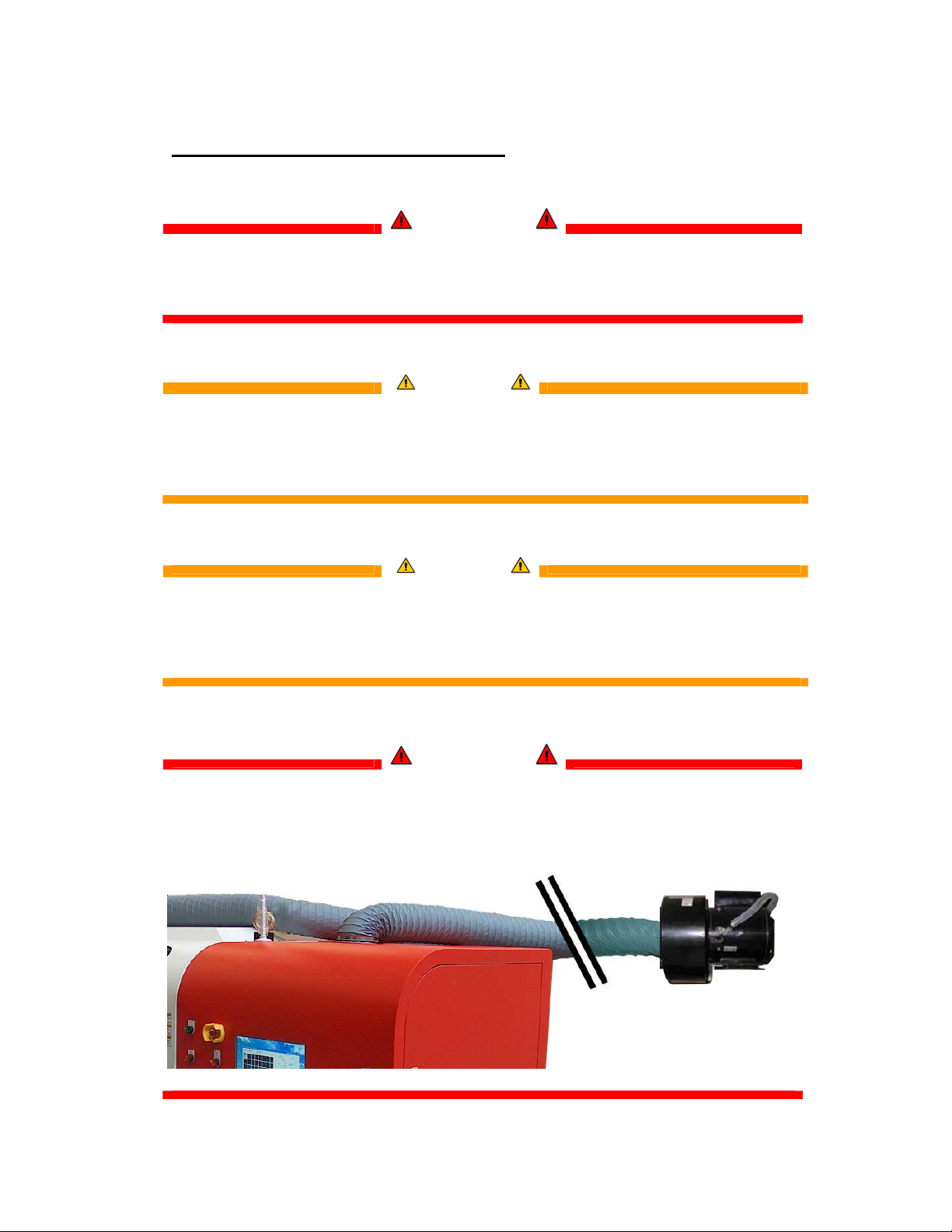
The Anapurna engines are equipped with an exhaust system to extract the
heat and the ozone gas, which is built up by the curing process.
Make sure the exhaust system leads to the outside air.
IMPORTANT
the equipment.
WARNING
WARNING
IMPORTANT
AB]]]]]]]]]]]]]]]]]]]]]]]]]]]]]]]]]]]]]]]]]]]]]]]]]]]]]]]]]]]]]]]]]]]]]]]]]]]]]]]]]]]]]]]]]]]]]]]]]]]]]]]]]]]]]]]]]]]]]]]]]]]]]]]]]]]]]]]]]]]]]]]]]]]]]]]]]]]]]]]]]]]]]]]]]]]]]]]]]]]]]]]]]]]]]]]]]]]]]]]]]]]]]]]]]]]]]]]]]]]]]]]]]]]]3]
8/08/2008
]
Page 4
:ANAPURNA XL² OPERATOR MANUAL
2. Printer Overview and Features.
2. Printer Overview and Features.
2. Printer Overview and Features.2. Printer Overview and Features.
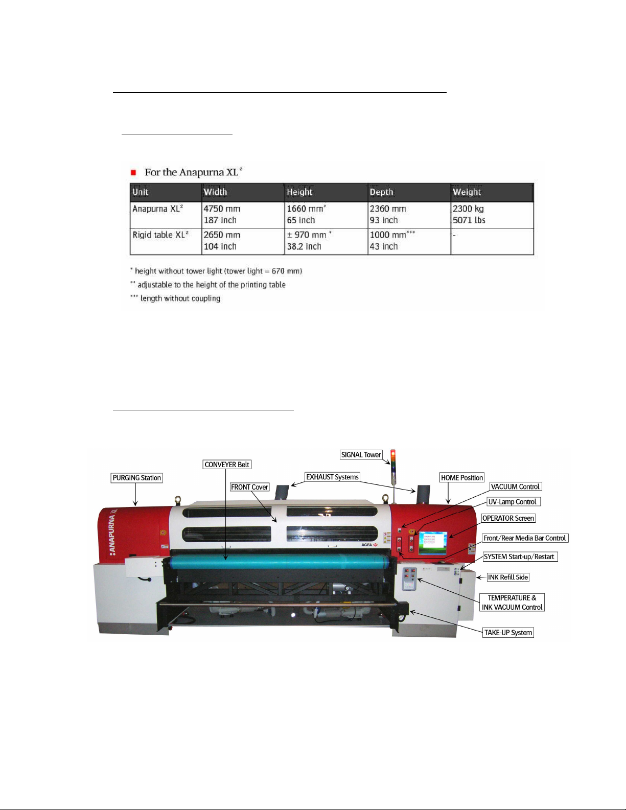
System Dimensions:
System Dimensions:
System Dimensions:System Dimensions:
ANAPURNA XL²
Max. media width: 2.5m (printable width: 2.48m)
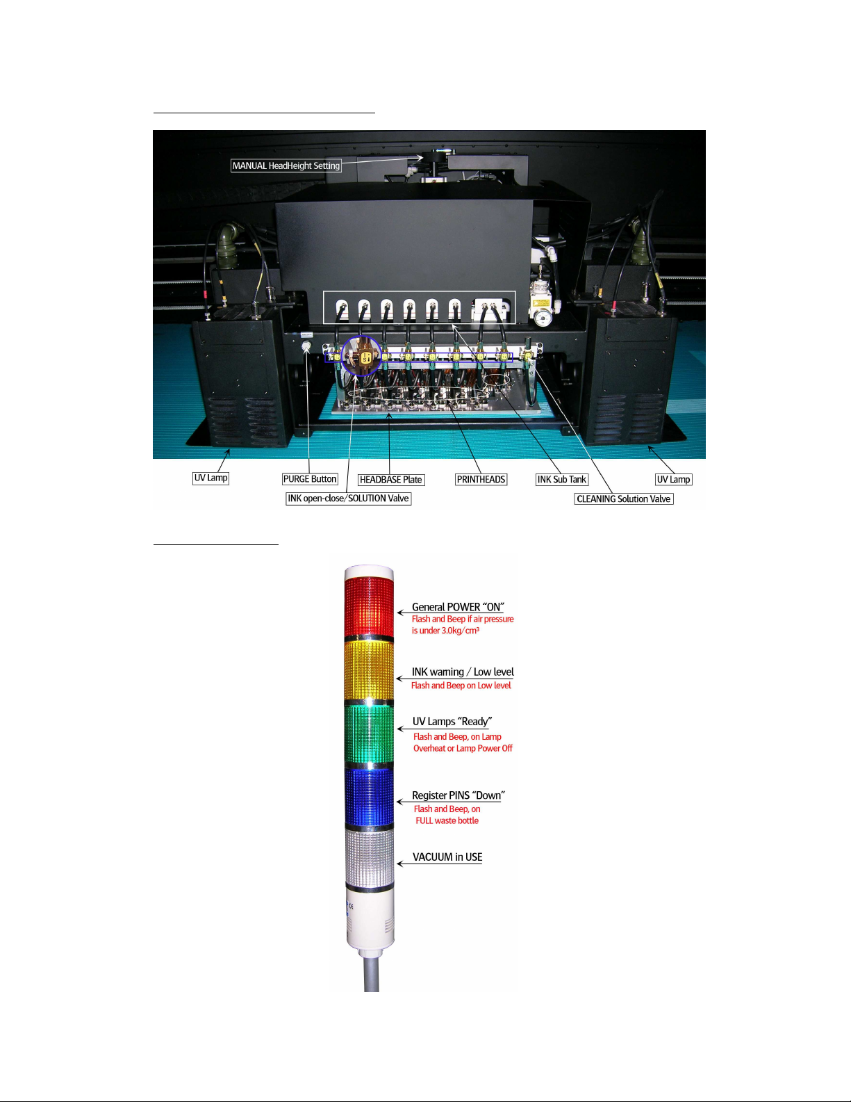
2.1. Front view, parts & locations
AB]]]]]]]]]]]]]]]]]]]]]]]]]]]]]]]]]]]]]]]]]]]]]]]]]]]]]]]]]]]]]]]]]]]]]]]]]]]]]]]]]]]]]]]]]]]]]]]]]]]]]]]]]]]]]]]]]]]]]]]]]]]]]]]]]]]]]]]]]]]]]]]]]]]]]]]]]]]]]]]]]]]]]]]]]]]]]]]]]]]]]]]]]]]]]]]]]]]]]]]]]]]]]]]]]]]]]]]]]]]]]]]]]]]]4]
8/08/2008
]
Page 5
:ANAPURNA XL² OPERATOR MANUAL
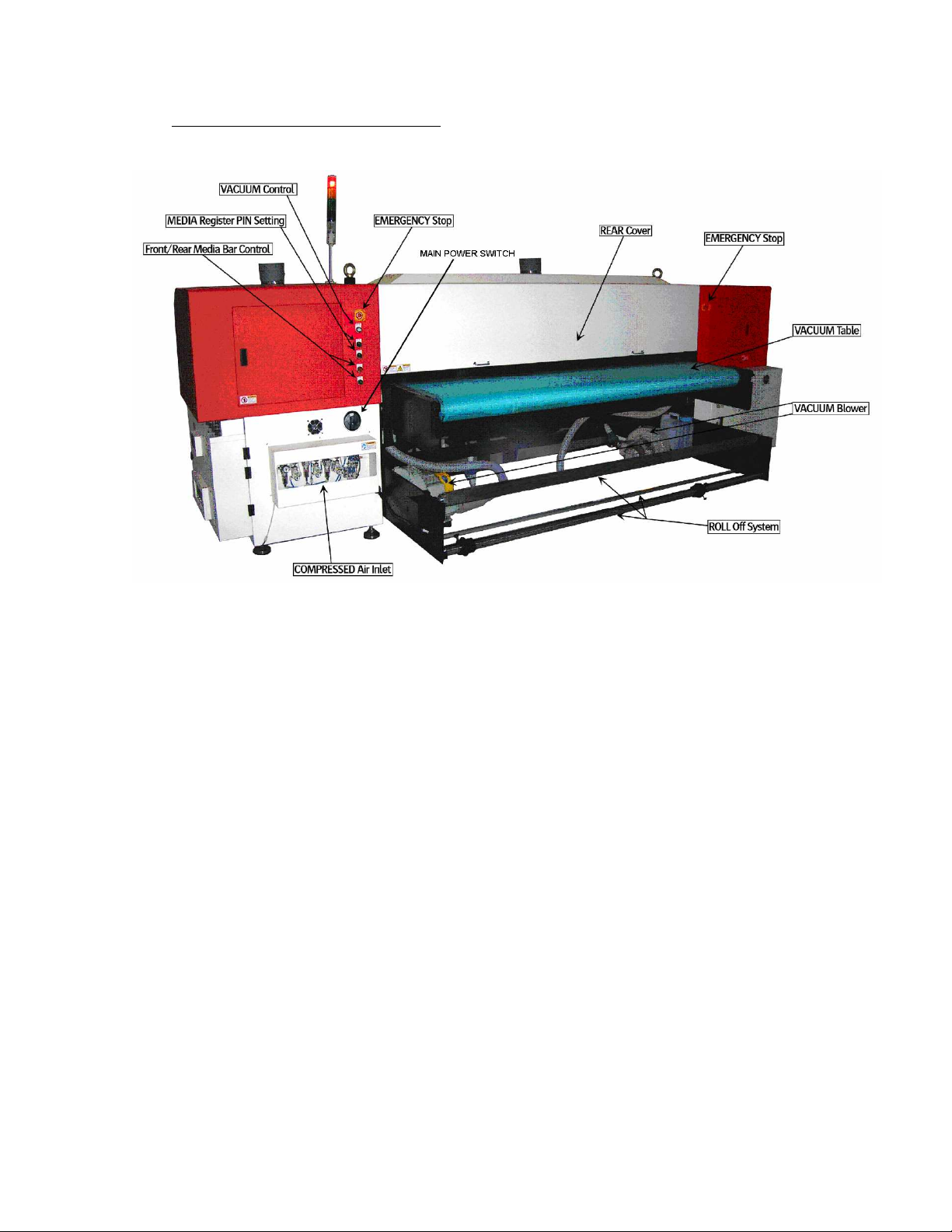
2.2. Rear view, parts & locations
AB]]]]]]]]]]]]]]]]]]]]]]]]]]]]]]]]]]]]]]]]]]]]]]]]]]]]]]]]]]]]]]]]]]]]]]]]]]]]]]]]]]]]]]]]]]]]]]]]]]]]]]]]]]]]]]]]]]]]]]]]]]]]]]]]]]]]]]]]]]]]]]]]]]]]]]]]]]]]]]]]]]]]]]]]]]]]]]]]]]]]]]]]]]]]]]]]]]]]]]]]]]]]]]]]]]]]]]]]]]]]]]]]]]]]5]
8/08/2008
]
Page 6
:ANAPURNA XL² OPERATOR MANUAL
OPENING THE COVER DURING PRINTING, WILL RESULT IN A CANCELLED PRINT !
ONLY
OPEN THE DOOR IN EMERGENCY SITUATION
S !
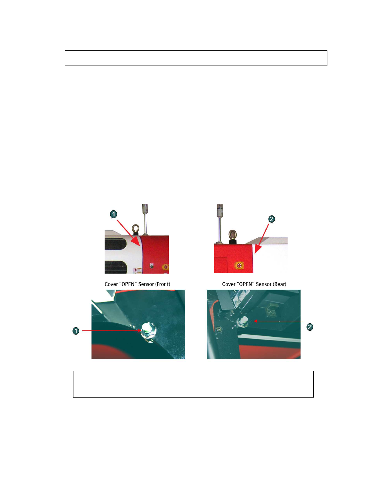
COVER “OPEN” SENSOR
This engine is equipped with a “safety sensor” on the Front and Rear cover.
Carrige movement and printing can only be done with covers closed.
.
1. When carriage is waiting: (Purge or Home)
When a cover is “open”, you will see the “door open error” on the screen, and the carriage
will not move to Home or Purge if requested.
2. During printing:
When you open the cover at this stage, the PRINT will be CANCELLED and the
UV lamp shutter will be closed automatically.
AB]]]]]]]]]]]]]]]]]]]]]]]]]]]]]]]]]]]]]]]]]]]]]]]]]]]]]]]]]]]]]]]]]]]]]]]]]]]]]]]]]]]]]]]]]]]]]]]]]]]]]]]]]]]]]]]]]]]]]]]]]]]]]]]]]]]]]]]]]]]]]]]]]]]]]]]]]]]]]]]]]]]]]]]]]]]]]]]]]]]]]]]]]]]]]]]]]]]]]]]]]]]]]]]]]]]]]]]]]]]]]]]]]]]]6]
8/08/2008
]
Page 7
:ANAPURNA XL² OPERATOR MANUAL
2.3. Head Carriage view, parts
2.4. Signal tower
AB]]]]]]]]]]]]]]]]]]]]]]]]]]]]]]]]]]]]]]]]]]]]]]]]]]]]]]]]]]]]]]]]]]]]]]]]]]]]]]]]]]]]]]]]]]]]]]]]]]]]]]]]]]]]]]]]]]]]]]]]]]]]]]]]]]]]]]]]]]]]]]]]]]]]]]]]]]]]]]]]]]]]]]]]]]]]]]]]]]]]]]]]]]]]]]]]]]]]]]]]]]]]]]]]]]]]]]]]]]]]]]]]]]]]7]
8/08/2008
]
Page 8
:ANAPURNA XL² OPERATOR MANUAL
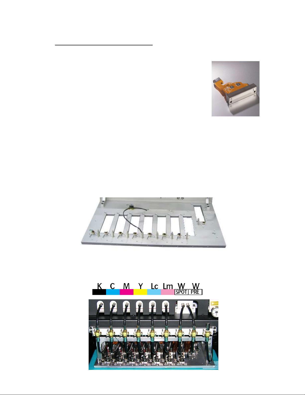
3. Head technology.
3. Head technology.
3. Head technology.3. Head technology.
Color heads:
Color heads:
Color heads:Color heads:
---- Spectra
Spectra Galaxy 256/5
Spectra Spectra
White heads:
White heads:
White heads:White heads:
---- Spectra
Spectra Galaxy 256/8
Spectra Spectra
---- 8 JA mounted in head base plate
8 JA mounted in head base plate
8 JA mounted in head base plate8 JA mounted in head base plate
---- Supported Color mode
Supported Color mode – fixed
Supported Color modeSupported Color mode
Galaxy 256/50 AAA JA (Jetting Assembly)
Galaxy 256/5Galaxy 256/5
Galaxy 256/80 AAA JA (Jetting Assembly)
Galaxy 256/8Galaxy 256/8
- Color Sequence:
0 AAA JA (Jetting Assembly)
0 AAA JA (Jetting Assembly)0 AAA JA (Jetting Assembly)
• Calibrated Drop Size: 50 pl
• 256 addressable jetting nozzles, single line
• Nozzle spacing: 256 microns (0,010”)
• Intrinsic resolution: 100 dpi
0 AAA JA (Jetting Assembly)
0 AAA JA (Jetting Assembly)0 AAA JA (Jetting Assembly)
• Calibrated Drop Size: 75 pl
• 256 addressable jetting nozzles, single line
• Nozzle spacing: 256 microns (0,010”)
• Intrinsic resolution: 100 dpi
• 7 heads in line
• 1 head mounted in front of the other heads, used for “Pre-White”.
AB]]]]]]]]]]]]]]]]]]]]]]]]]]]]]]]]]]]]]]]]]]]]]]]]]]]]]]]]]]]]]]]]]]]]]]]]]]]]]]]]]]]]]]]]]]]]]]]]]]]]]]]]]]]]]]]]]]]]]]]]]]]]]]]]]]]]]]]]]]]]]]]]]]]]]]]]]]]]]]]]]]]]]]]]]]]]]]]]]]]]]]]]]]]]]]]]]]]]]]]]]]]]]]]]]]]]]]]]]]]]]]]]]]]]8]
8/08/2008
]
Page 9
:ANAPURNA XL² OPERATOR MANUAL
4. :Anapurna UV Curable Ink.
4. :Anapurna UV Curable Ink.
4. :Anapurna UV Curable Ink.4. :Anapurna UV Curable Ink.
4.1. General information
- The :Anapurna UV curable ink is specially developed for
best performance on the :Anapurna engine.
- Sharp printing, vibrant colors on a wide range of media
- Ensures dry and instant ready prints with excellent outdoor durability
- Use of light inks
• Enhance apparent output resolution by using Light Cyan and
Light Magenta
• Results in smooth highlights
- Ink usage: ± 10ml/m², all colors together (6)
4.2. Color gamut
- Agfa Inks tuned towards the ISO Standard 12647 (2004)
- Calculated nr of colors (Volume calculated within Monaco CMS)
- ISO Standard 12647: 770.000 colors
- :Anapurna Ink on :Anapurna printing in:
» 6 pass
6 pass : 830.000 colors
6 pass6 pass
» 8 pass
8 pass : 850.000 colors
8 pass8 pass
» 12 pass
12 pass : 1.080.000 colors
12 pass12 pass
» 16 pass
16 pass :
16 pass16 pass
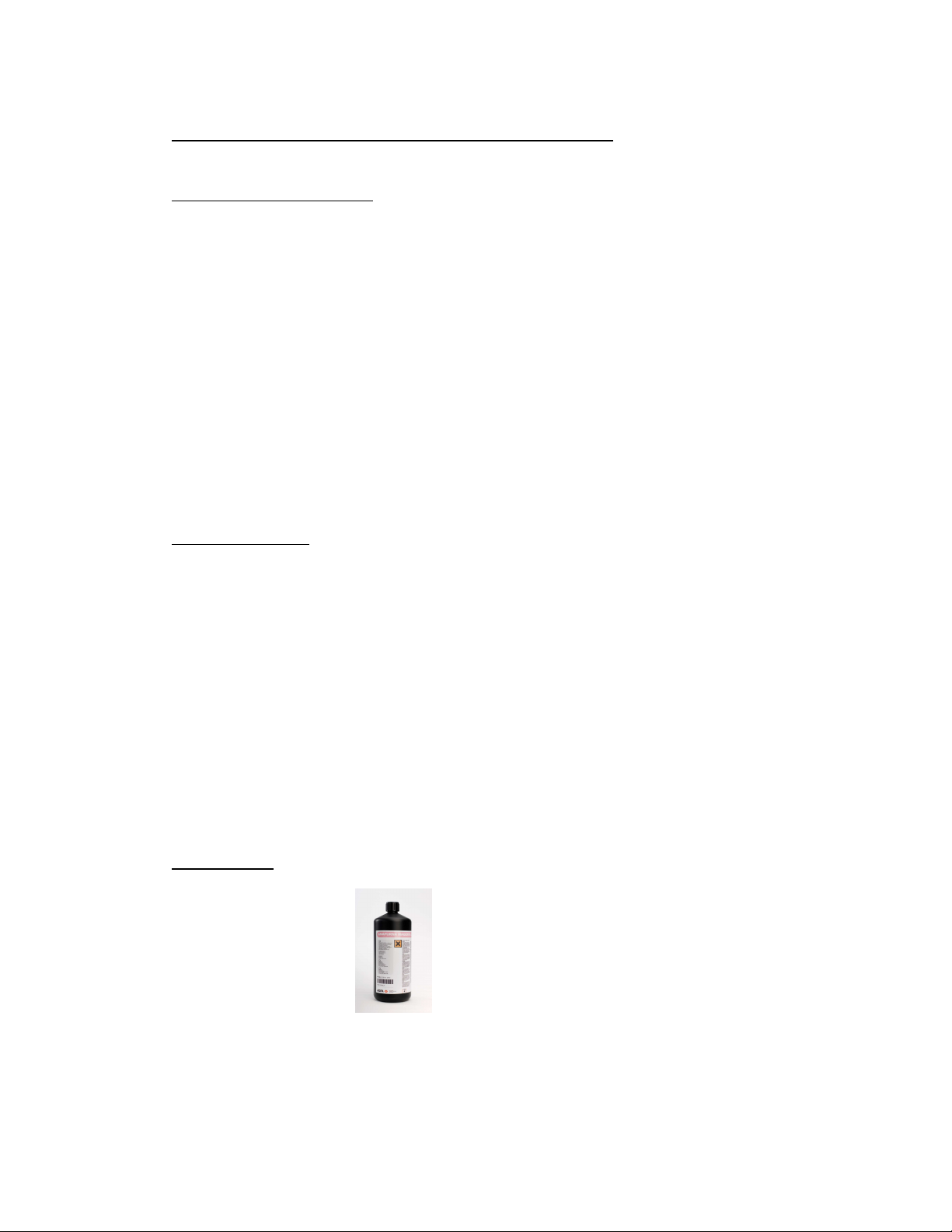
4.3. Packing
- 1L bottle, packed per 4
::::Anapurna Cyan ::::Anapurna Magenta
::::Anapurna Light Cyan ::::Anapurna Light Magenta
::::Anapurna Yellow ::::Anapurna White
::::Anapurna Black ::::Anapurna Cleaning Solution
AB]]]]]]]]]]]]]]]]]]]]]]]]]]]]]]]]]]]]]]]]]]]]]]]]]]]]]]]]]]]]]]]]]]]]]]]]]]]]]]]]]]]]]]]]]]]]]]]]]]]]]]]]]]]]]]]]]]]]]]]]]]]]]]]]]]]]]]]]]]]]]]]]]]]]]]]]]]]]]]]]]]]]]]]]]]]]]]]]]]]]]]]]]]]]]]]]]]]]]]]]]]]]]]]]]]]]]]]]]]]]]]]]]]]]9]
8/08/2008
]
Page 10
:ANAPURNA XL² OPERATOR MANUAL
5555. Ink
. Ink Circuit
. Ink. Ink
Circuit....
Circuit Circuit
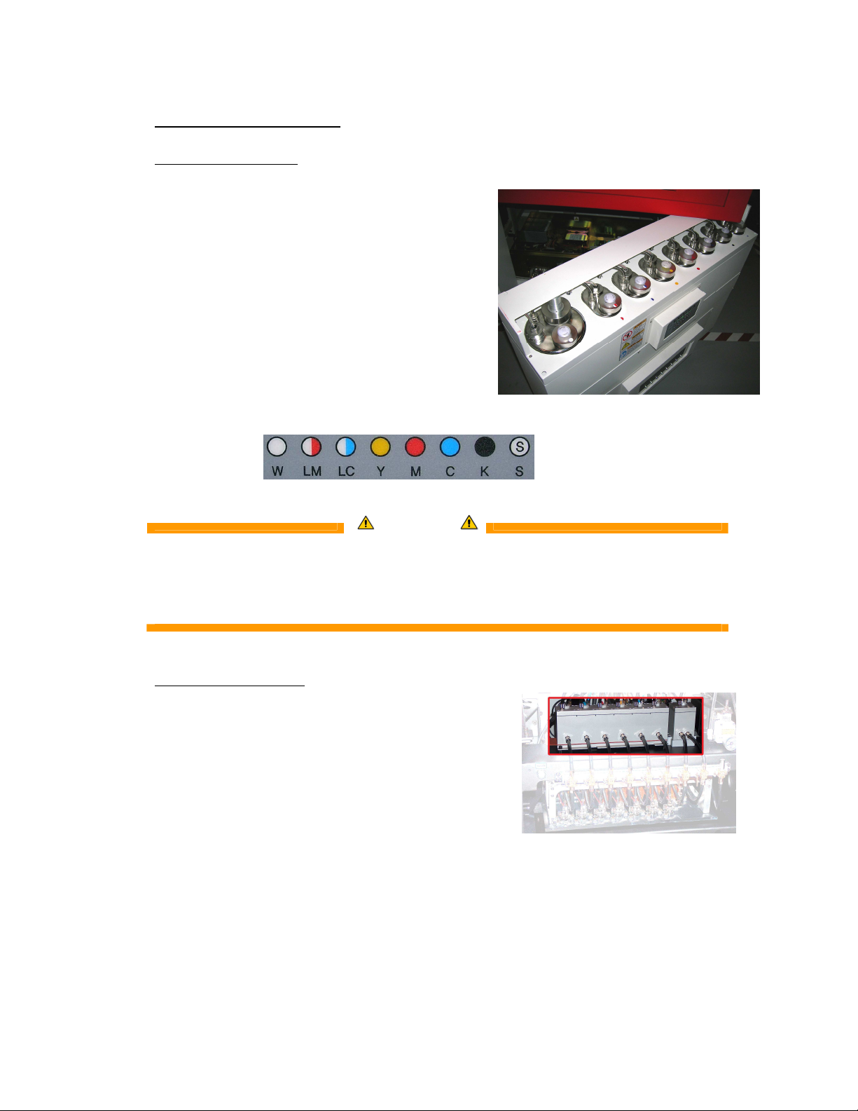
5.1. Main ink tanks
- The main ink tanks are located on the right
side of the engine.
- 1.6 liter per color
- Low level detection at 0.3lm, enough
to finish the currently printing job.
Audible & visual alarm on the Signal tower.
- Ink can be refilled in while printing
- White ink tank has a continuous working
stirring rod inside.
- Tanks:
At that point, you can pour in a complete 1L bottle, and you won’t have any
WARNING
ONLY refill with the 1liter bottle, when the low level alarm goes off.
left over ink remaining in the bottle!!
5.2. Auto ink supply
- From the ink tank, ink is pumped into
the “Sub ink tank”, which is positioned
on the Head Carriage.
- The Sub ink tank is temperature
controlled, and has a content
of 35ml per color
AB]]]]]]]]]]]]]]]]]]]]]]]]]]]]]]]]]]]]]]]]]]]]]]]]]]]]]]]]]]]]]]]]]]]]]]]]]]]]]]]]]]]]]]]]]]]]]]]]]]]]]]]]]]]]]]]]]]]]]]]]]]]]]]]]]]]]]]]]]]]]]]]]]]]]]]]]]]]]]]]]]]]]]]]]]]]]]]]]]]]]]]]]]]]]]]]]]]]]]]]]]]]]]]]]]]]]]]]]]]]]]]]]]]]]10]
8/08/2008
]
Page 11
:ANAPURNA XL² OPERATOR MANUAL
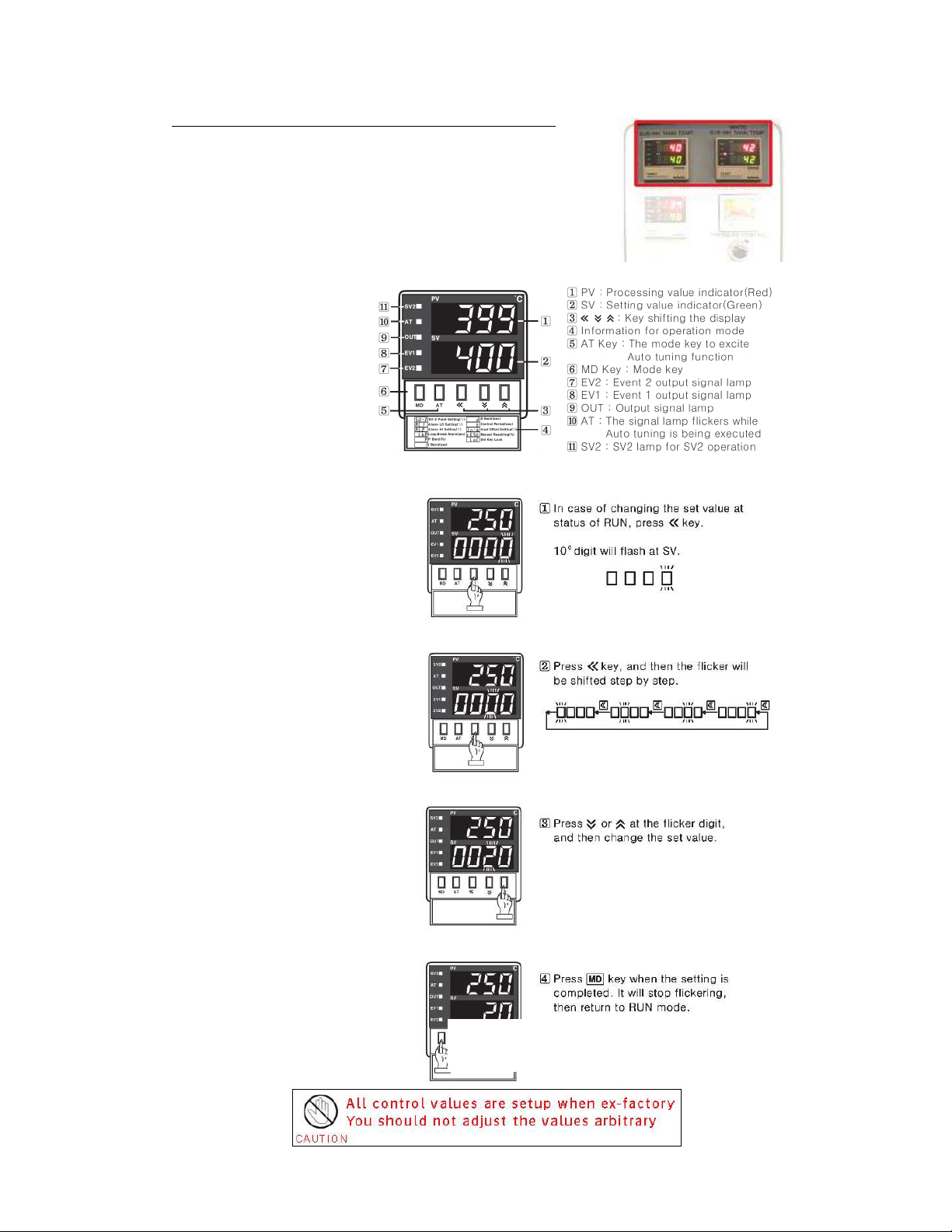
5.3. Sub Ink Tank and head base temperatures
---- Temperature setting “Sub Ink Tank”
Color: 40°C
White Ink: 40°C when in use (up to max 45°C)
25°C when not in use
-
- Temperature setting “Headbase plate” : 40°C
--
- Read out:
- How to make changes:
At this stage, you also need to Press the “AT”
At this stage, you also need to Press the “AT”
At this stage, you also need to Press the “AT” At this stage, you also need to Press the “AT”
button, to close the procedure.
button, to close the procedure.
button, to close the procedure.button, to close the procedure.
AB]]]]]]]]]]]]]]]]]]]]]]]]]]]]]]]]]]]]]]]]]]]]]]]]]]]]]]]]]]]]]]]]]]]]]]]]]]]]]]]]]]]]]]]]]]]]]]]]]]]]]]]]]]]]]]]]]]]]]]]]]]]]]]]]]]]]]]]]]]]]]]]]]]]]]]]]]]]]]]]]]]]]]]]]]]]]]]]]]]]]]]]]]]]]]]]]]]]]]]]]]]]]]]]]]]]]]]]]]]]]]]]]]]]]11]
8/08/2008
]
Page 12
:ANAPURNA XL² OPERATOR MANUAL
THE
THE THE
THE
APPROPRIATE
APPROPRIATEAPPROPRIATE
APPROPRIATE
WAY OF WORKING, FOR PERFORMING A NOZZLE CHECK,
WAY OF WORKING, FOR PERFORMING A NOZZLE CHECK, WAY OF WORKING, FOR PERFORMING A NOZZLE CHECK,
WAY OF WORKING, FOR PERFORMING A NOZZLE CHECK,
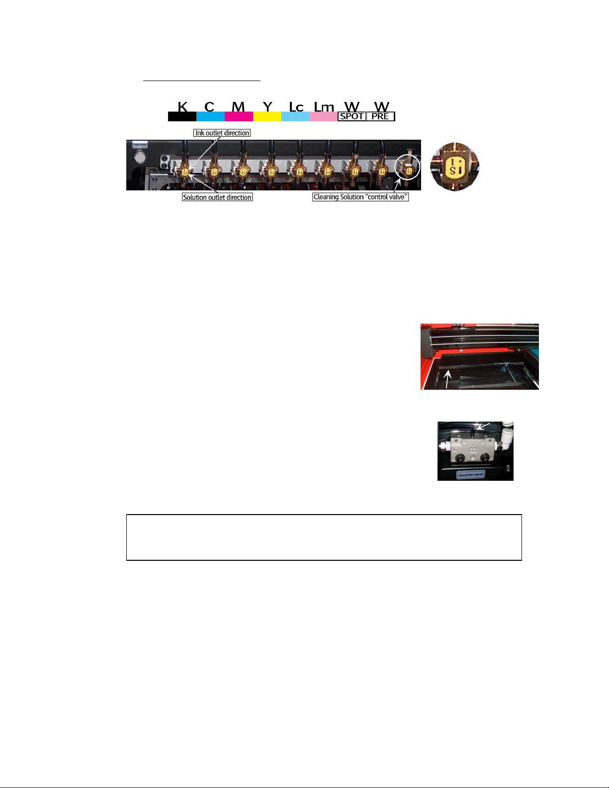
5.4. The 2-Way valves
- Normal printing:
- The color valves are positioned in the “I” direction.
The ink can flow to the head.
- Purging the heads:
- In case of clogged nozzles, or misfiring nozzles;
Push the “Purge” button at very short intervals,
this will cause ink flowing through the heads,
this will un-clog the missing nozzles.
(make sure the Grid is pushed to the back)
- Cleaning the heads with Cleaning solution:
- The color valves must be “closed”, set them to
the “S” direction. Now, the ink flow to the heads is closed.
Open the Cleaning Solution “control valve” on the right.
When you now push the “Solution-Purge” button on
the BACK of the shuttle, Cleaning solution will flow
through your heads to un-clog the missing nozzles.
AND JUDGING MISFIRING NOZZLES,
AND JUDGING MISFIRING NOZZLES,
AND JUDGING MISFIRING NOZZLES, AND JUDGING MISFIRING NOZZLES,
CAN BE FOUND IN THE MAINTENANCE CHAPTER.
CAN BE FOUND IN THE MAINTENANCE CHAPTER.
CAN BE FOUND IN THE MAINTENANCE CHAPTER.CAN BE FOUND IN THE MAINTENANCE CHAPTER.
AB]]]]]]]]]]]]]]]]]]]]]]]]]]]]]]]]]]]]]]]]]]]]]]]]]]]]]]]]]]]]]]]]]]]]]]]]]]]]]]]]]]]]]]]]]]]]]]]]]]]]]]]]]]]]]]]]]]]]]]]]]]]]]]]]]]]]]]]]]]]]]]]]]]]]]]]]]]]]]]]]]]]]]]]]]]]]]]]]]]]]]]]]]]]]]]]]]]]]]]]]]]]]]]]]]]]]]]]]]]]]]]]]]]]]12]
8/08/2008
]
Page 13
:ANAPURNA XL² OPERATOR MANUAL
“Pooling”: ink build up underneath the print head,
causing nozzle failure.
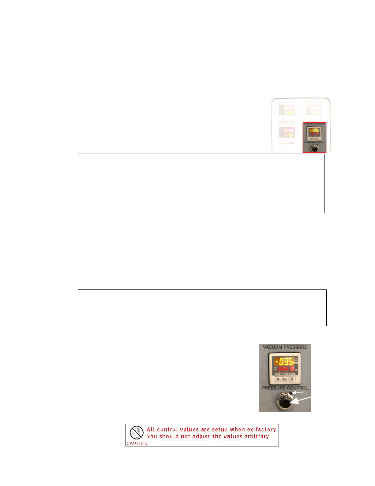
5.5. Negative pressure setting
- Ink supply by means of negative pressure:
By means of negative pressure, the ink is kept in the print heads.
A too high setting will cause missing nozzles, or no ink firing at all.
When the pressure is too low, the ink will leak out of the heads.
The Neg. Pressure should be set to -.0.36
During the day, the negative pressure indication can raise
a little bit when the engine becomes hot. This is a normal
behaviour and as user you don’t have to correct the value
at that moment;
When you have to raise the under pressure to a higher then normal value to avoid
ink dripping out of the heads (pooling), then this can be an indication that some air
got into the ink supply lines; In this case refer to the maintenance section to do a
large purge and get rid of air in the nozzles by leaking the heads with low under
pressure. If this is not sufficient, air can be present in the ink filter because ink
levels went low in the main tank; In that case, you have to bleed the air out of the
ink filters, also explained in the maintenance section.
When using White ink:
It is possible that the Neg. Pressure needs to be tuned towards “-.038”, to
get a stable nozzle behavior for the White heads.
With the white ink, a higher temperature will result in a lower viscosity
(more liquid state), which can lead to ink “Pooling” underneath the print
head.
As the head needs to fire drops, the fired drops are not getting through the pool of
ink underneath the head. An increase of Neg. Pressure, (-.038) will bring the ink
more upwards into the meniscus of the print head, thus preventing the pooling.
- How to make changes:
Un-lock the black knob by pushing
the “A”-switch to the left.
You can now turn the black knob to
make changes in the pressure.
Push the “A” switch back to secure the knob.
AB]]]]]]]]]]]]]]]]]]]]]]]]]]]]]]]]]]]]]]]]]]]]]]]]]]]]]]]]]]]]]]]]]]]]]]]]]]]]]]]]]]]]]]]]]]]]]]]]]]]]]]]]]]]]]]]]]]]]]]]]]]]]]]]]]]]]]]]]]]]]]]]]]]]]]]]]]]]]]]]]]]]]]]]]]]]]]]]]]]]]]]]]]]]]]]]]]]]]]]]]]]]]]]]]]]]]]]]]]]]]]]]]]]]]13]
8/08/2008
]
Page 14

:ANAPURNA XL² OPERATOR MANUAL
5.6. Waste Tank
- When the waste tank is full, the blue lamp
will flash on the Signal tower, together with
a beep-alarm.
- The waste tank is located under the conveyor belt,
on the Purge-side of the engine.
Open the tap underneath to empty the tank.
- Make sure the UV-ink is kept separately from
solvent ink, do not mix them in a waste container.
AB]]]]]]]]]]]]]]]]]]]]]]]]]]]]]]]]]]]]]]]]]]]]]]]]]]]]]]]]]]]]]]]]]]]]]]]]]]]]]]]]]]]]]]]]]]]]]]]]]]]]]]]]]]]]]]]]]]]]]]]]]]]]]]]]]]]]]]]]]]]]]]]]]]]]]]]]]]]]]]]]]]]]]]]]]]]]]]]]]]]]]]]]]]]]]]]]]]]]]]]]]]]]]]]]]]]]]]]]]]]]]]]]]]]]14]
8/08/2008
]
Page 15
:ANAPURNA XL² OPERATOR MANUAL
6666.
. UV
UV Curing System
. .
Curing System....
UVUV
Curing System Curing System
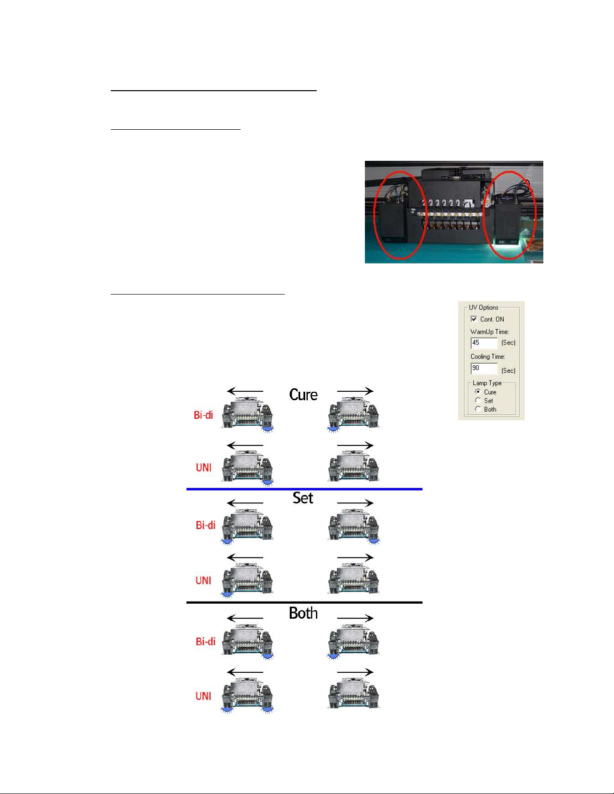
6.1. General information
-
2 UV sources positioned in front of and behind head base plate
- High speed on-the-fly curing
- Curing power: 120 W/cm
- 2 fixed settings: Full and half strength
- Air cooled lamp-house
- Quick and easy replacement of the UV-bulbs
(Always change both the lamps !!)
- Use of an automated shutter system
6.2. Curing setup and sequences
- Settings in software:
- Lamps continous ON
- WarmUp Time
- Cooling Time
- Lamp Type: Cure
(lamp stays “ON” for next print; longest lifetime)
(when turning back on the UV lamps, before ready state)
(after turning off the UV lamps)
(Default),
Set or Both
AB]]]]]]]]]]]]]]]]]]]]]]]]]]]]]]]]]]]]]]]]]]]]]]]]]]]]]]]]]]]]]]]]]]]]]]]]]]]]]]]]]]]]]]]]]]]]]]]]]]]]]]]]]]]]]]]]]]]]]]]]]]]]]]]]]]]]]]]]]]]]]]]]]]]]]]]]]]]]]]]]]]]]]]]]]]]]]]]]]]]]]]]]]]]]]]]]]]]]]]]]]]]]]]]]]]]]]]]]]]]]]]]]]]]]15]
8/08/2008
]
Page 16
:ANAPURNA XL² OPERATOR MANUAL
When switching ON the UV
When switching ON the UVWhen switching ON the UV
When switching ON the UV
----
lamps,
lamps, lamps,
lamps,
don’t switch
don’t switch don’t switch
don’t switch
them from “Off” to “Full”
them from “Off” to “Full”them from “Off” to “Full”
them from “Off” to “Full”
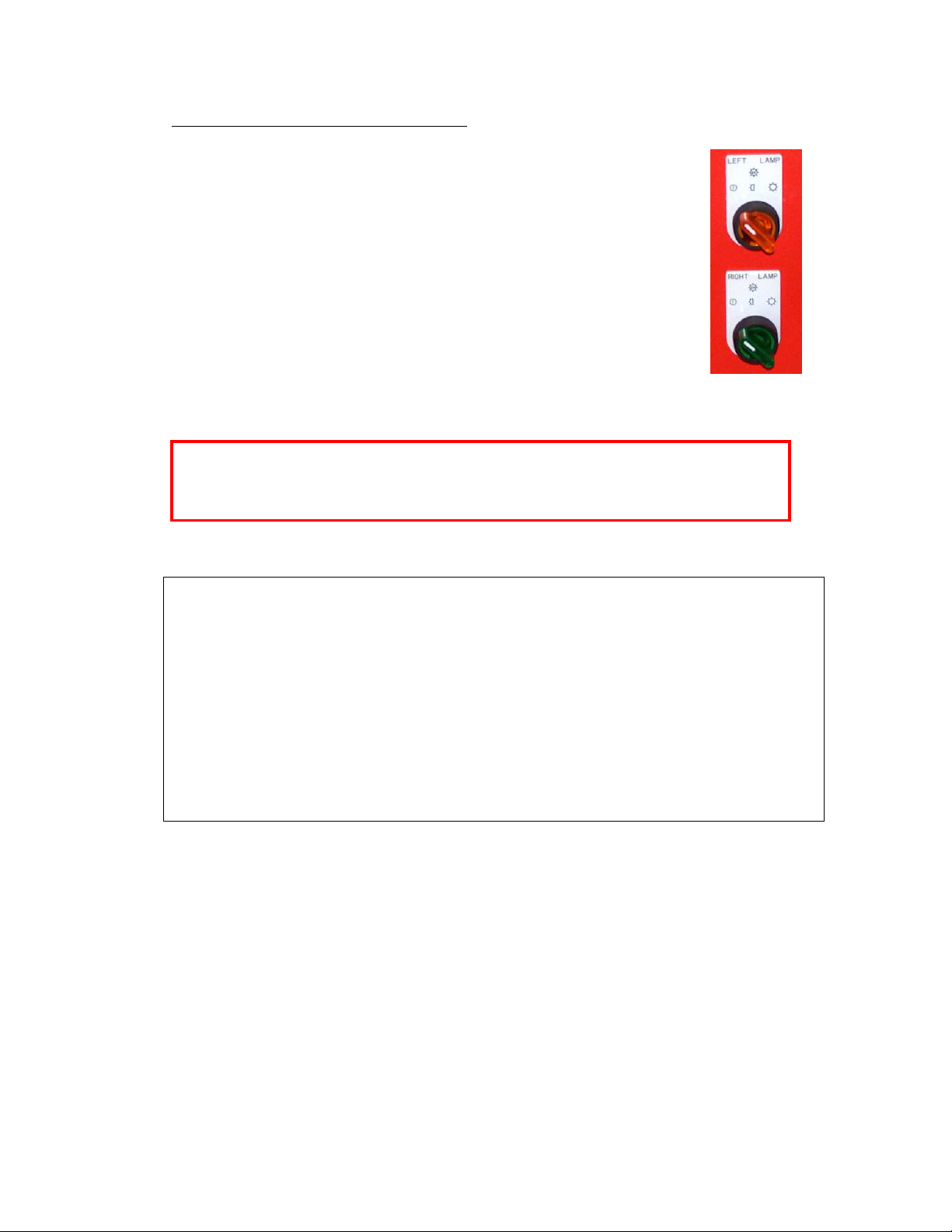
6.3. Uni- and Bi-directional printing
- For Bi-directional printing, both UV lamps need to be used.
(curing is done on the fly in both printing directions)
- For Uni-directional printing, only the right UV lamp will be used.
(curing is only done when the shuttle is moving from right to left)
Depending on the heat-resistance/thickness of your media,
you can set the UV lamp power to “Half” or “Full” power.
By default, “Full” power should be used whenever possible.
By default, “Full” power should be used whenever possible.
By default, “Full” power should be used whenever possible.By default, “Full” power should be used whenever possible.
power at once. Wait 2 seconds at “Half” power before switching them to
power at once. Wait 2 seconds at “Half” power before switching them to
power at once. Wait 2 seconds at “Half” power before switching them to power at once. Wait 2 seconds at “Half” power before switching them to
“Full“ power. Use the same procedure when going from Full power to Off.
“Full“ power. Use the same procedure when going from Full power to Off.
“Full“ power. Use the same procedure when going from Full power to Off.“Full“ power. Use the same procedure when going from Full power to Off.
Note about UV-lamp life time:
The lamp life time is not only depending on the numbers of hours that a lamp generated
light; Especially gas-discharged bulbs, the type that is used in general on all UV-curing
systems, have a life time that is strongly influenced by the number of times that the bulb
is switched ON and OFF. As a general rule, one can state that switching a bulb ON and
OFF counts for about 40 minutes of head life time.
To maximize the useful life time of a bulb, one should not turn the lamps OFF after having
made a print if a next job will be printed in the coming 20 to 30 minutes; For that,
‘continuous ON’ should be checked in the UV options of the setup menu, and a user only
has to switch the lamps off if the machine will not be used for at least an half hour.
Due to the physics of the lamp discharge lamps, a UV-bulb can also not ignite when it is
hot; For that, the UV-bulb is first cooled down for the set period after a user switched it
off, before the bulb will ignite again if the user turns back on the UV-switch.
AB]]]]]]]]]]]]]]]]]]]]]]]]]]]]]]]]]]]]]]]]]]]]]]]]]]]]]]]]]]]]]]]]]]]]]]]]]]]]]]]]]]]]]]]]]]]]]]]]]]]]]]]]]]]]]]]]]]]]]]]]]]]]]]]]]]]]]]]]]]]]]]]]]]]]]]]]]]]]]]]]]]]]]]]]]]]]]]]]]]]]]]]]]]]]]]]]]]]]]]]]]]]]]]]]]]]]]]]]]]]]]]]]]]]]16]
8/08/2008
]
Page 17
:ANAPURNA XL² OPERATOR MANUAL
7777.
. Printing Table
Printing Table....
. .
Printing TablePrinting Table
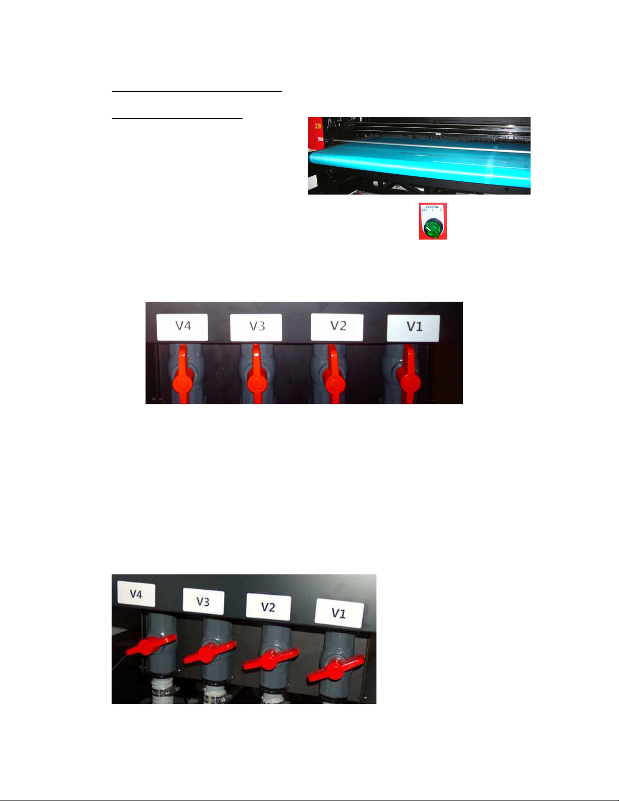
7.1. General information
- Woven Conveyor belt
- Transport is done by a step-motor
- On the table are 4 vacuum-zones with a variable strength.
The table is evenly divided in 4 compartments. The 2 most
right compartments are driven by ring blower number 1;
The 2 most left compartments are driven by ring blower number 2.
The ring blower switch can be switched on in that order.
- The vacuum of each compartment can be lowered by closing the manual air valves
located at the rear right side.
- The valve numbers V1 till V4 are numbered from home position (V1) till purge
position (V4). The border of each compartment is indicated with a yellow sticker
on the box beam.
It is very important to set the air valves depending on the media width and media
type that you are using;
As a general rule, one has to close the corresponding air valve to the 30 degrees
angle position (so close the valve for 2/3 of its range) if the corresponding table
compartment is completely covered by the media. The valve of a partly covered
compartment has to stay completely open (upright position as shown in the picture
above).
Fail to do that will have as result that flexible media can get crunched up at the rear
side of the vacuum table due to a too high vacuum and can cause a head crash if the
ripples are coming under the heads.
Air Valve position if all 4 compartments are fully covered (full width media).
More details for specific roll-to-roll media are given at the end of this manual.
AB]]]]]]]]]]]]]]]]]]]]]]]]]]]]]]]]]]]]]]]]]]]]]]]]]]]]]]]]]]]]]]]]]]]]]]]]]]]]]]]]]]]]]]]]]]]]]]]]]]]]]]]]]]]]]]]]]]]]]]]]]]]]]]]]]]]]]]]]]]]]]]]]]]]]]]]]]]]]]]]]]]]]]]]]]]]]]]]]]]]]]]]]]]]]]]]]]]]]]]]]]]]]]]]]]]]]]]]]]]]]]]]]]]]]17]
8/08/2008
]
Page 18

:ANAPURNA XL² OPERATOR MANUAL
7.2. Belt Tension control
The belt tension is of key importance to get a reliable media transport; After some
usage, the belt loose its tension, and the user has to correct the tension to bring it
again to the initial tension. At least once a month, the user has to check and correct
the tension. Guideline is that the belt is put under such high tension that a user can
shuffle his hand for not more than 50-to-80% of the finger length in between the belt
and the vacuum table (at front side).
If he can put the hand further under the belt, the belt needs re-tension:
- remove the metal covers on the backside (both left and right),
- rotate the screw at the REAR stand to CW (clock wise) to put the tension higher
Do this correction with the same numbers of turns left and right.
Unequal tension:
- if the tension left and right is different, the belt can shift to one end of the roll. This
can be seen when looking to the hourglass shaped side rolls underneath the vacuum
table: if the belt touches the guider and curls up, the belt has to be re-aligned.
The way to do that is explained in the next paragraph.
AB]]]]]]]]]]]]]]]]]]]]]]]]]]]]]]]]]]]]]]]]]]]]]]]]]]]]]]]]]]]]]]]]]]]]]]]]]]]]]]]]]]]]]]]]]]]]]]]]]]]]]]]]]]]]]]]]]]]]]]]]]]]]]]]]]]]]]]]]]]]]]]]]]]]]]]]]]]]]]]]]]]]]]]]]]]]]]]]]]]]]]]]]]]]]]]]]]]]]]]]]]]]]]]]]]]]]]]]]]]]]]]]]]]]]18]
8/08/2008
]
Page 19

:ANAPURNA XL² OPERATOR MANUAL
7.3. Maintenance
- Always make sure, when printing “borderless”, that the belt is masked,
so printing on the belt is reduced to a minimum. When you have printed onto the
Conveyor belt and the ink is cured, it can not be removed anymore, and ink can be
build up under the conveyor belt and result in a loss of vacuum.
- re-align the belt (tensioning the belt : see previous paragraph):
AB]]]]]]]]]]]]]]]]]]]]]]]]]]]]]]]]]]]]]]]]]]]]]]]]]]]]]]]]]]]]]]]]]]]]]]]]]]]]]]]]]]]]]]]]]]]]]]]]]]]]]]]]]]]]]]]]]]]]]]]]]]]]]]]]]]]]]]]]]]]]]]]]]]]]]]]]]]]]]]]]]]]]]]]]]]]]]]]]]]]]]]]]]]]]]]]]]]]]]]]]]]]]]]]]]]]]]]]]]]]]]]]]]]]]19]
8/08/2008
]
Page 20

:ANAPURNA XL² OPERATOR MANUAL
7.4. Replacement of Conveyor belt
- Vacuum can become insufficient when the belt is completely printed.
The Conveyor belt therefore is a Spare Part, and can be ordered as such.
AB]]]]]]]]]]]]]]]]]]]]]]]]]]]]]]]]]]]]]]]]]]]]]]]]]]]]]]]]]]]]]]]]]]]]]]]]]]]]]]]]]]]]]]]]]]]]]]]]]]]]]]]]]]]]]]]]]]]]]]]]]]]]]]]]]]]]]]]]]]]]]]]]]]]]]]]]]]]]]]]]]]]]]]]]]]]]]]]]]]]]]]]]]]]]]]]]]]]]]]]]]]]]]]]]]]]]]]]]]]]]]]]]]]]]20]
8/08/2008
]
Page 21

:ANAPURNA XL² OPERATOR MANUAL
8888.
. Maintenance
Maintenance....
. .
MaintenanceMaintenance
8.1. General information
- At the end of the day, and when you stop
printing, the shuttle needs to be placed in the
“Purge position”. For overnight or longer
standstill times, an absorbing cloth or paper has
to be placed onto the “Grid” underneath the
shuttle and this grid must be pulled to the front.
This will take care to catch the ink drops that are
jetted continuously to weep the heads, and
avoids that the ink drops will contaminate the
whole area around the shuttle.
- Dispose that paper in the morning, when you want to start printing again with the
printer.
- A default “Weeping” time is set in the engine
software to keep the heads open, this small amount of ink is collected in
the underneath waste box, which leads to a waste tank underneath the engine.
(See chapter 5.6, on how to empty)
- Place some towels in front of the Purge grid, this will help to
keep the area clean, it’s advisable to replace them weekly.
- During a print job, the “Purge Grid” must be placed forward when you start to print.
This prevents the UV light reflection onto the ink heads and so prevents to cure the
ink into the head nozzles when the UV-lamps pass over the much lower purge tray.
It also prevents the ink in the underneath waste box from getting cured by the UV
lamps during the printing stage.
AB]]]]]]]]]]]]]]]]]]]]]]]]]]]]]]]]]]]]]]]]]]]]]]]]]]]]]]]]]]]]]]]]]]]]]]]]]]]]]]]]]]]]]]]]]]]]]]]]]]]]]]]]]]]]]]]]]]]]]]]]]]]]]]]]]]]]]]]]]]]]]]]]]]]]]]]]]]]]]]]]]]]]]]]]]]]]]]]]]]]]]]]]]]]]]]]]]]]]]]]]]]]]]]]]]]]]]]]]]]]]]]]]]]]]21]
8/08/2008
]
Page 22

:ANAPURNA XL² OPERATOR MANUAL
8.2. Daily Maintenance – Nozzle check/purge
- Check the state of the “Purge” and “Home” station Grid that no cured ink is build up
that can get in contact with the heads.
- Perform a nozzle check and make sure all nozzles are firing.
- In the Control program, push “Test”, and select “Jet Test”.
- Place a white copy (A4-size) paper on the printing table, if no media is present.
- Move the head to the HOME position
The left margin is given by the number that is displayed in the textbox in the
test menu. The default number (500) refers to the position indicated by the
white dots on the beam box.
The “red” area shows the placement of the Spot- and Pré-white if it’s turned
on (use a black or colored paper to see the white).
- Switch on the vacuum.
- select ‘Test’ to start the print.
- Evaluate the nozzle check for missing nozzles.
The Jet Test must be carried out at a correct head height. Place the A4 paper onto
your media, or print it directly on a flexible media that is loaded and for which the
head height is adjusted.
- In case of nozzle failure:
Move carriage to PURGE position
Push the underneath GRID backwards
AB]]]]]]]]]]]]]]]]]]]]]]]]]]]]]]]]]]]]]]]]]]]]]]]]]]]]]]]]]]]]]]]]]]]]]]]]]]]]]]]]]]]]]]]]]]]]]]]]]]]]]]]]]]]]]]]]]]]]]]]]]]]]]]]]]]]]]]]]]]]]]]]]]]]]]]]]]]]]]]]]]]]]]]]]]]]]]]]]]]]]]]]]]]]]]]]]]]]]]]]]]]]]]]]]]]]]]]]]]]]]]]]]]]]]22]
8/08/2008
]
Page 23

:ANAPURNA XL² OPERATOR MANUAL
(*)
Clean the heads with a fiber
-
free cloth,
(**)
Hold
a white A4
-
paper underneath t
he base plate to check the nozzles.
Little purge:
Little purge:
Little purge:Little purge:
- Close all heads that are OK (switch them to the “S” position)
- Push the “Purge” button frequently, at very short intervals.
- Open all heads again (switch them back to the “I” position)
- Clean the heads with a fiber-free cloth. (*)
- Check on “weeping” (**)
by wiping from back to front on each head separately.
(Use backside of cloth, or a new cloth for every next head)
The intention is to capture the ink when the heads are weeping. (± 10sec)
You will see vertical lines appearing on the sheet, check them on interruption.
LLLLarge
arge purge:
purge:
argearge
purge: purge:
- With all the heads open….. (switch them all to the “I” position)
- Push and hold the “Purge” button for a longer time (2 sec.), end the procedure by
pushing the “Purge” button again, but now frequent, at very short intervals.
- Clean the heads with a fiber-free cloth. (*)
- Check on “weeping” (**)
IF NOZZLE FAILLURE STILL PERSISTS…. Proceed with following steps:
- Set the Neg. Pressure to “0”, leave the system for 1-2 minutes
(Ink will now start dripping out the heads)
- Restore the Neg. Pressure back to “-.036”
- Clean the heads with a fiber-free cloth.
- Check on “weeping” (**)
AB]]]]]]]]]]]]]]]]]]]]]]]]]]]]]]]]]]]]]]]]]]]]]]]]]]]]]]]]]]]]]]]]]]]]]]]]]]]]]]]]]]]]]]]]]]]]]]]]]]]]]]]]]]]]]]]]]]]]]]]]]]]]]]]]]]]]]]]]]]]]]]]]]]]]]]]]]]]]]]]]]]]]]]]]]]]]]]]]]]]]]]]]]]]]]]]]]]]]]]]]]]]]]]]]]]]]]]]]]]]]]]]]]]]]23]
8/08/2008
]
Page 24

:ANAPURNA XL² OPERATOR MANUAL
When purging with “Cle
aning
-
Soluti
on”, always work
in three
steps.
Solution Valve
Solution Valve Solution Valve
Solution Valve
SSSS
olution
olutionolution
olution
----
Curtain
CurtainCurtain
Curtain
CLEANING
CLEANING failing heads
CLEANINGCLEANING
failing heads::::
failing heads failing heads
- Set the valves of the failing heads to the “S” position.
- Set the Solution valve to “S”.
- Push the “Solution-Purge” button on the back of the carriage.
(Keep pushing in a sequence of 2 seconds push and 4 seconds
release until you see a CLEAR “Solution-Curtain”
under the heads, then stop pushing)
- Leave the heads leaking in this condition for at least 5 minutes.
- Set all the valves back to “I”.
- Give a little purge.
- Set the Neg. Pressure to “0”, leave the system for 1 minute
(Ink will now start dripping out the heads)
- Restore the Neg. Pressure back to “-.036”
- Clean the heads with a fiber-free cloth.
- Check on “weeping” (**)
To clean all 8 heads, first purge the 4 right heads (Lc, Lm, W1, W2), close them,
and in the second stage, purge the remaining 4 left heads (K, C, M, Y).
Finally, open the 4 right heads again, and purge all 8 heads together now.
By doing so, you’ll have the most optimal cleaning pressure.
AB]]]]]]]]]]]]]]]]]]]]]]]]]]]]]]]]]]]]]]]]]]]]]]]]]]]]]]]]]]]]]]]]]]]]]]]]]]]]]]]]]]]]]]]]]]]]]]]]]]]]]]]]]]]]]]]]]]]]]]]]]]]]]]]]]]]]]]]]]]]]]]]]]]]]]]]]]]]]]]]]]]]]]]]]]]]]]]]]]]]]]]]]]]]]]]]]]]]]]]]]]]]]]]]]]]]]]]]]]]]]]]]]]]]]24]
8/08/2008
]
Page 25

:ANAPURNA XL² OPERATOR MANUAL
ENCODER STRIP
ENCODER STRIPENCODER STRIP
ENCODER STRIP
SUB
SUBSUB
SUB
----
AIRTANK
AIRTANKAIRTANK
AIRTANK
8.3. Weekly Maintenance
The weekly maintenance combines different small handlings, and a storage procedure:
- Check the state of the “Purge” and “Home” station Grid, and remove eventually
cured ink off the grid and out of the underneath tray. The grid itself can be taken out
of the tray to have easy access to the tray. The tray at home position does not have a
drain pipe, so liquid ink in the tray has to be removed with an absorbing paper or
cloth. Use a filling-knife or a wide screwdriver, to cut off the cured ink that’s on the
ribs.
- Check the waste ink tank underneath the printing
table; dispose the ink according to local government
regulations. (Also see chapter 5.6.)
- Clean the “encoder” strip with alcohol or aceton.
(Situated upfront on the main beam)
ENGINE STORAGE AT THE END OF THE WEEK:
- Move the carriage to the Purge position.
- Flush cleaning solution through the heads:
- First flush the 4 right heads (Lc, Lm, W1, W2) and close them,
and in the second stage, flush the remaining 4 left heads (K, C, M, Y).
- Finally, open the 4 right heads again, and flush all 8 heads together now.
By doing so, you’ll have the most optimal cleaning pressure.
- Switch all heads and the Solution valve back to “I”.
- Set the Neg. Vacuum Pressure to “0”, leave the system for 1 minute
(Ink will now start dripping out the heads)
- Empty the sub-airtank by opening the tap (use a tube into a PE-bottle)
(Sub-airtank is located at back of carriage)
- Restore the Neg. Pressure back to “-.036”
- Perform a Large Purge
- Clean the Head Base Plate with a cloth
- Clean the heads with a fiber-free cloth.
- Check the nozzle’s on “weeping” or with a Jet Test.
- If all nozzles are present, the engine can be left in the Purge Position,
with the Grid pulled forwards and an absorbing paper or cloth onto the grid.
- Replace the towels in front of the Purge grid, and check/clean the whole Purge
station environment, the front of the UV-lamps might need some cleaning too.
- Clean the Quartz plate of both UV-lamp houses with alcohol. (underside of lamps)
AB]]]]]]]]]]]]]]]]]]]]]]]]]]]]]]]]]]]]]]]]]]]]]]]]]]]]]]]]]]]]]]]]]]]]]]]]]]]]]]]]]]]]]]]]]]]]]]]]]]]]]]]]]]]]]]]]]]]]]]]]]]]]]]]]]]]]]]]]]]]]]]]]]]]]]]]]]]]]]]]]]]]]]]]]]]]]]]]]]]]]]]]]]]]]]]]]]]]]]]]]]]]]]]]]]]]]]]]]]]]]]]]]]]]]25]
8/08/2008
]
Page 26

:ANAPURNA XL² OPERATOR MANUAL
8.4. Long Stand Still
This procedure must be carried out:
- If the engine’s “Stand Still Time” is 1 week or longer…
- If the vacuum pressure is going to be closed down…
SHUTDOWN -- preparing the engine:
- Move the carriage to the Purge position.
- Flush cleaning solution through the heads:
- First flush the 4 right heads (Lc, Lm, W1, W2) and close them,
and in the second stage, flush the remaining 4 left heads (K, C, M, Y).
- Finally, open the 4 right heads again, and flush all 8 heads together now.
By doing so, you’ll have the most optimal cleaning pressure.
- Leave all ink valves in the “S” position, set the Solution valve to “I”.
- On the Engine’s Control Panel, perform a “Head Lift-Up”;
The carriage will go to the highest position.
- Clean the Head Base Plate with a cloth
- Set the Vacuum Pressure to “0”. (Negative Pressure)
- Mount the “Capping Plate” underneath the Head Base Plate.
- use a plastic foil to wrap around the capping plate (new foil every time)
- place a support between the capping plate and the grid.
- bring down the carriage by turning manually, until it’s fixed.
(use some packing material as support)
- Push the emergency stop, and leave it pushed in! (restart-safety)
- Shut down the engine’s PC.
AB]]]]]]]]]]]]]]]]]]]]]]]]]]]]]]]]]]]]]]]]]]]]]]]]]]]]]]]]]]]]]]]]]]]]]]]]]]]]]]]]]]]]]]]]]]]]]]]]]]]]]]]]]]]]]]]]]]]]]]]]]]]]]]]]]]]]]]]]]]]]]]]]]]]]]]]]]]]]]]]]]]]]]]]]]]]]]]]]]]]]]]]]]]]]]]]]]]]]]]]]]]]]]]]]]]]]]]]]]]]]]]]]]]]]26]
8/08/2008
]
Page 27

:ANAPURNA XL² OPERATOR MANUAL
- Switch OFF the main power, by using the main-switch
(big round turn switch at the rear of the engine).
- Turn off the compressed air.
---- THE ENGINE IS NOW READY FOR A LONG STAND STILL
THE ENGINE IS NOW READY FOR A LONG STAND STILL ----
THE ENGINE IS NOW READY FOR A LONG STAND STILLTHE ENGINE IS NOW READY FOR A LONG STAND STILL
STARTUP -- preparing the engine to print again:
- Remove the capping plate. Verify that the headbase plate is turned higher than
anything that is laying down onto the conveyor belt.
- Turn the compressed air back on. (still at “0” on display)
- Turn ON the main power switch at the rear side of the engine.
- Turn and pull the emergency stop back outwards.
- Startup the engine and switch the engine’s PC back on.
(ATTN.: carriage will move slowly to the Home position)
- Move the carriage back to the Purge position.
- Switch all ink valves back to “I”
- Perform a long purge, until you see ink appearing out of the heads.
- Let the ink drip for 1 minute
- Set the vacuum pressure back to “-.036”. (Negative Pressure)
- Clean the heads and base plate.
- Perform a nozzle check and purge again if necessary.
---- THE ENGINE IS NOW READY
THE ENGINE IS NOW READY TO PRINT AGAIN
THE ENGINE IS NOW READY THE ENGINE IS NOW READY
TO PRINT AGAIN ----
TO PRINT AGAIN TO PRINT AGAIN
AB]]]]]]]]]]]]]]]]]]]]]]]]]]]]]]]]]]]]]]]]]]]]]]]]]]]]]]]]]]]]]]]]]]]]]]]]]]]]]]]]]]]]]]]]]]]]]]]]]]]]]]]]]]]]]]]]]]]]]]]]]]]]]]]]]]]]]]]]]]]]]]]]]]]]]]]]]]]]]]]]]]]]]]]]]]]]]]]]]]]]]]]]]]]]]]]]]]]]]]]]]]]]]]]]]]]]]]]]]]]]]]]]]]]]27]
8/08/2008
]
Page 28

:ANAPURNA XL² OPERATOR MANUAL
8.5. Bleeding air out of the ink filters
When suddenly an increase of the under pressure is needed to hold the ink properly in the
nozzles without pooling, there is a big chance that an air-bubble is sitting into the ink
tank; This can be caused by a previous low ink level in the main ink tank, by having
poured ink into the main tank that contained a lot of air or just an accumulation over time
of small air bubbles in the ink.
At that time, the user has to bleed the air out of the ink filters. Only then, an accurate ink
supply can occur.
AB]]]]]]]]]]]]]]]]]]]]]]]]]]]]]]]]]]]]]]]]]]]]]]]]]]]]]]]]]]]]]]]]]]]]]]]]]]]]]]]]]]]]]]]]]]]]]]]]]]]]]]]]]]]]]]]]]]]]]]]]]]]]]]]]]]]]]]]]]]]]]]]]]]]]]]]]]]]]]]]]]]]]]]]]]]]]]]]]]]]]]]]]]]]]]]]]]]]]]]]]]]]]]]]]]]]]]]]]]]]]]]]]]]]]28]
8/08/2008
]
Page 29
:ANAPURNA XL² OPERATOR MANUAL
9999.
. Media Setup
Media Setup....
. .
Media SetupMedia Setup
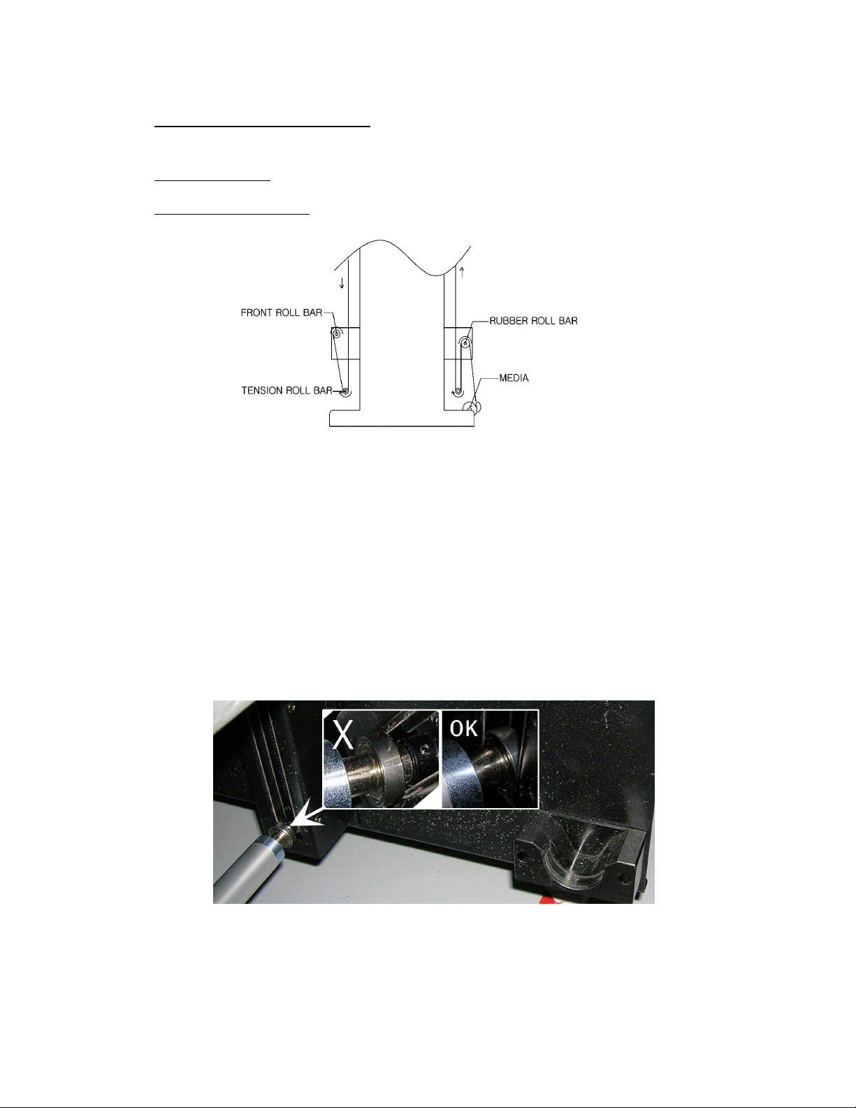
9.1. Roll to Roll
9.1.1. Auto Feed System
The Auto feed system has two tension bars, holding a constant tension.
Those tension bars prevent distortion and waves on the media.
The Rear roll bar will unwind the media, with a constant tension and height
controlling. These are acquired from the “signal sensors”.
The Front roll bar will wind the printed media, holding a constant tension to reduce
distortion. Wind direction can be reversed.
Make sure you always insert the “Tension Roll Bar” at a correct way.
The ball bearing must be inside the guide.
When inserting, make sure both side’s are positioned as high as possible into
the left and right unit, then gently lower both sides, the bar must stay completely
horizontal for best use.
AB]]]]]]]]]]]]]]]]]]]]]]]]]]]]]]]]]]]]]]]]]]]]]]]]]]]]]]]]]]]]]]]]]]]]]]]]]]]]]]]]]]]]]]]]]]]]]]]]]]]]]]]]]]]]]]]]]]]]]]]]]]]]]]]]]]]]]]]]]]]]]]]]]]]]]]]]]]]]]]]]]]]]]]]]]]]]]]]]]]]]]]]]]]]]]]]]]]]]]]]]]]]]]]]]]]]]]]]]]]]]]]]]]]]]29]
8/08/2008
]
Page 30

:ANAPURNA XL² OPERATOR MANUAL
Take-Up Motor
Box
9.1.2. Take-up control system
(1) In Manual Mode, motor rotates CW
(2) In Manual Mode, motor rotates CCW
(1)+(2) You can RESET by pushing buttons for 1 sec
(3) - In Auto Mode: select motor direction (CW or CCW)
- In Manual Mode: select motor (Back or Front)
(4) Select Mode (Manual or Auto)
9.1.3. Roll Alignment
When the roll media is loaded, measure the distance from the right
side (A) to the point where you want to start printing.
Enter this value on the engine’s Control Program, as a Left Margin.
Make sure that the distance between
Make sure that the distance between edge of the vacuum table and edge of the
Make sure that the distance between Make sure that the distance between
media is identical the same front and rear; A difference of 1mm is already too much
media is identical the same front and rear; A difference of 1mm is already too much
media is identical the same front and rear; A difference of 1mm is already too much media is identical the same front and rear; A difference of 1mm is already too much
and will to make sure that the media will not run straight and starts to shift to one
and will to make sure that the media will not run straight and starts to shift to one
and will to make sure that the media will not run straight and starts to shift to one and will to make sure that the media will not run straight and starts to shift to one
end.
end.
end.end.
edge of the vacuum table and edge of the
edge of the vacuum table and edge of the edge of the vacuum table and edge of the
9.1.4. Vacuum
see chapter 7.1 for details regarding the use of the vacuum valves. A detailed
explanation of how to put the media in an optimal way, is explained at the end of this
document under ‘Tips and Tricks’
AB]]]]]]]]]]]]]]]]]]]]]]]]]]]]]]]]]]]]]]]]]]]]]]]]]]]]]]]]]]]]]]]]]]]]]]]]]]]]]]]]]]]]]]]]]]]]]]]]]]]]]]]]]]]]]]]]]]]]]]]]]]]]]]]]]]]]]]]]]]]]]]]]]]]]]]]]]]]]]]]]]]]]]]]]]]]]]]]]]]]]]]]]]]]]]]]]]]]]]]]]]]]]]]]]]]]]]]]]]]]]]]]]]]]]30]
8/08/2008
]
Page 31

:ANAPURNA XL² OPERATOR MANUAL
9.2. Rigid Media
9.2.1. Rigid Support tables
- One table for use on the front, and one table for use on the back are delivered
with the machine. (Standard table; full engine width, and 1.20m long)
9.2.2. Rigid Alignment
9.2.2.1. Media Register Pins and side guiders:
When turning the upper “Media Set” button to position 1, the left side pin –
indicated as ‘1’ in the below picture, goes down. This is the side alignment pin of
your first rigid (rigid A). This rigid can be small or even have full engine width.
When you turn the upper “Media Set” button to position 2, also side alignment pin
nr.2 in the below picture will come down, allowing you to load two rigid media.
AB]]]]]]]]]]]]]]]]]]]]]]]]]]]]]]]]]]]]]]]]]]]]]]]]]]]]]]]]]]]]]]]]]]]]]]]]]]]]]]]]]]]]]]]]]]]]]]]]]]]]]]]]]]]]]]]]]]]]]]]]]]]]]]]]]]]]]]]]]]]]]]]]]]]]]]]]]]]]]]]]]]]]]]]]]]]]]]]]]]]]]]]]]]]]]]]]]]]]]]]]]]]]]]]]]]]]]]]]]]]]]]]]]]]]31]
8/08/2008
]
Page 32

:ANAPURNA XL² OPERATOR MANUAL
With the lower “Media Set” button, you drop all the 6 top alignment pins (pins
indicated under number 3 in the above picture). These are the front pins to which
you put the front edge of your media.
After placement of the media onto the belt, you have to switch the vacuum on,
and move all the pins back upwards.
While Media Set pins are lowered, the blue light will lighten up on the tower, and
neither carriage movement nor printing is possible.
For longer media, the side guiders with rolls can be used located on the guider at
the rear of the vacuum table.
9.2.2.2. Top and Left Margin Setup:
The “A” and “B” positions, the “origin-point” at the corner of your media, are
known distances. The “A” point has as approximately position: Top margin = 300
mm and Left Margin = 50 mm. Depending on the position onto the media where
the image has to be printed, you have to add the image offset to these numbers.
These numbers can be entered in the Control program.
Image placement for printing on two rigid media, must be done on Rip level.
Important
When printing on heat sensitive media, always make sure the right
UV lamp is going passed the media, on the point of returning.
(otherwise there will be more heat at the left side of the media,
which can cause media cockling or produce a yellowish shine on some media)
This can be arranged on the Rip level by entering a blanco space at the
right of the pictures.
AB]]]]]]]]]]]]]]]]]]]]]]]]]]]]]]]]]]]]]]]]]]]]]]]]]]]]]]]]]]]]]]]]]]]]]]]]]]]]]]]]]]]]]]]]]]]]]]]]]]]]]]]]]]]]]]]]]]]]]]]]]]]]]]]]]]]]]]]]]]]]]]]]]]]]]]]]]]]]]]]]]]]]]]]]]]]]]]]]]]]]]]]]]]]]]]]]]]]]]]]]]]]]]]]]]]]]]]]]]]]]]]]]]]]]32]
8/08/2008
]
Page 33

:ANAPURNA XL² OPERATOR MANUAL
Remark: The engine has also a parameter ‘Mark Center Offset’ for this which
is default set on value ‘5000’ means 2.5 cm besides the image edge.
This value can be changed by the technician, but if this value is made higher,
the bidirectional alignment value has to be changed accordingly, and you will
be restricted in total image width if you want to print at another time at full
width of the engine onto your media (the extra displacement counts off of your
maximum image width). For that we advise to add the blanco space in
Wasatch and leave the engine setting unchanged.
9.2.3. Vacuum
With rigid media, the vacuum settings must be chosen according the covered area on
the conveyor belt. When printing on two rigid media, activate both the vacuum tables
(1&2). (more info: see chapter 7.1)
9.3. Media Tension Bars
The engine has got one roller bar at the front, and one at the back.
They are located underneath the front- and back-covers. These bars will help to keep
the media flat while it’s been transported on the conveyor belt.
It can be used on Roll media, as well as on rigid media.
You can lower the bars, by switching the “FRONT” or “REAR” buttons.
When you’ve taken out a bar, and want to re-insert it:
Make sure both side’s are positioned as high as possible into the left
and right unit, then gently lower both sides, the bar must stay completely
horizontal for best use.
AB]]]]]]]]]]]]]]]]]]]]]]]]]]]]]]]]]]]]]]]]]]]]]]]]]]]]]]]]]]]]]]]]]]]]]]]]]]]]]]]]]]]]]]]]]]]]]]]]]]]]]]]]]]]]]]]]]]]]]]]]]]]]]]]]]]]]]]]]]]]]]]]]]]]]]]]]]]]]]]]]]]]]]]]]]]]]]]]]]]]]]]]]]]]]]]]]]]]]]]]]]]]]]]]]]]]]]]]]]]]]]]]]]]]]33]
8/08/2008
]
Page 34

:ANAPURNA XL² OPERATOR MANUAL
10
10.
. Head Base
1010
10.1. Automatic “Head Base Height” Setup
Head Base –––– Height Control
. .
Head Base Head Base
This is done in the “Head Gap Control”, which can be found in the Setup Parameter
window.
Height Control....
Height Control Height Control
Check or change the following Parameters to set the Head Base Height:
Gap:
Enter the value that you want the “Head Base” to be above the media surface.
(Recommended value: 1.5mm; For heat sensitive media, you can go higher to
avoid that too much heat is accepted by the media, and as a result the media
is extended and can touch the head or is printed with bad quality.
Change of this value requires however other values as ‘offset’ and ‘bialignment offset parameters.
Don’t forget to save the Setup parameter list to keep the change.
AB]]]]]]]]]]]]]]]]]]]]]]]]]]]]]]]]]]]]]]]]]]]]]]]]]]]]]]]]]]]]]]]]]]]]]]]]]]]]]]]]]]]]]]]]]]]]]]]]]]]]]]]]]]]]]]]]]]]]]]]]]]]]]]]]]]]]]]]]]]]]]]]]]]]]]]]]]]]]]]]]]]]]]]]]]]]]]]]]]]]]]]]]]]]]]]]]]]]]]]]]]]]]]]]]]]]]]]]]]]]]]]]]]]]]34]
8/08/2008
]
Page 35

:ANAPURNA XL² OPERATOR MANUAL
Check Distance:
This parameter indicates the measure position offset where you have your
media onto the belt and where the “Set Gap” must be executed. If your media
is not completely flat, this must be the HIGHEST point on your media.
Remark:
Since the gap sensor is however located in the middle of the shuttle, the value
that has to be put in the textbox is the measured offset onto the table +
400mm (400 = half a shuttle width). So if the media has to be measured at
1m offset, you have to fill in ‘1400’ .
Reference:
This is the height at the point where the “Head Base” will wait for an onscreen confirmation, before going down to set the desired “Gap”. This value is
a mechanical parameter that is unique for each engine, and may not be
changed by the user.
When all parameters are Ok, load the media onto the table, click on the “Set Gap”
Procedure : When you’ve entered a “1.5mm Gap” & “Check Distance: 1200mm”
- The Head Base will stay in the Home position and go up to the highest
limit position (> 50mm).
- After this movement, you have to confirm on-screen that the carriage is
clear to move, to the “Check Distance” position.
- Shuttle will move to the left until the measure spoon is around 800mm
from the start of the vacuum table and will come down to set the Gap.
- A sensor plate (called spoon) will become visible underneath the Head
Base, to make
contact with the media surface.
- The Head Base will lower to his “Reference” point, and you’ll have
to confirm on-screen (Ready to Set Gap) to make the last fine-tuning. This
is lowering from the Reference point, to the desired Head Base Height (1.5
mm Gap)
- When this is done, you’ll get following message: “Check Gap and
Ready to Go to Home Position”. At this point, you can verify
the correct Gap setting with a measuring device.
Click on OK, and the Set Gap is completed.
AB]]]]]]]]]]]]]]]]]]]]]]]]]]]]]]]]]]]]]]]]]]]]]]]]]]]]]]]]]]]]]]]]]]]]]]]]]]]]]]]]]]]]]]]]]]]]]]]]]]]]]]]]]]]]]]]]]]]]]]]]]]]]]]]]]]]]]]]]]]]]]]]]]]]]]]]]]]]]]]]]]]]]]]]]]]]]]]]]]]]]]]]]]]]]]]]]]]]]]]]]]]]]]]]]]]]]]]]]]]]]]]]]]]]]35]
8/08/2008
]
Page 36

:ANAPURNA XL² OPERATOR MANUAL
11
11.
. :Anapurna Control Pr
1111
11.1. Control Program Menu
:Anapurna Control Program
. .
:Anapurna Control Pr:Anapurna Control Pr
The :Anapurna Control program on the engine’s PC:
ogram....
ogramogram
1 : IMAGE display window
2 : IMAGE SIZE display window
3 : Move Carriage to “Purge” position
4 : Move Carriage to ‘Home” position
5 : Move loaded media (jog) Fwd/Back(***)
6 : STATUS Message display window
7 : Display Printing Progress
8 : Set Top (forward) and Left Margin
(*) When you open an image file (.rtl), which is sent from the Rip station, you’ll get
an on-screen preview and it will also show the image size and nr. of passes the
image is ripped for. (if an image is ripped for 6 pass, and you print it at 8 pass, it
will result in an un-proportionally scaled printout)
(**) Regardless the image file, you can always choose between printing
Uni- or Bi-directional.
AB]]]]]]]]]]]]]]]]]]]]]]]]]]]]]]]]]]]]]]]]]]]]]]]]]]]]]]]]]]]]]]]]]]]]]]]]]]]]]]]]]]]]]]]]]]]]]]]]]]]]]]]]]]]]]]]]]]]]]]]]]]]]]]]]]]]]]]]]]]]]]]]]]]]]]]]]]]]]]]]]]]]]]]]]]]]]]]]]]]]]]]]]]]]]]]]]]]]]]]]]]]]]]]]]]]]]]]]]]]]]]]]]]]]]36]
9 : Setup Menu, to Change Parameters
10 : Press to Open the TEST menu
11 : Select PASS mode
12 : Push to start Printing
13 : Open image file(.rtl) to be printed (*)
14 : Lift head to highest position (>50mm)
15 : Select to Uni-Directional printing (**)
16 : Single Media Feed steps
8/08/2008
]
Page 37

:ANAPURNA XL² OPERATOR MANUAL
(***) The ‘JOG’ function allows to fill in a number of mm that the media has to move
in forward direction (positive number) or backwards direction (negative number).
The button below: ‘CUT’ will move the media (typically used for roll-to-sheet) to
the front where the user can cut off the already made print with a knife or pair of
scissors; After this he has to press onto the same button which then has the text
‘Return’ to feed the media back to the position were it was laying down before
after finishing the previous print.
11.2. Setup Parameter Menu
A “.dat”-file contains all engine parameters, such as the UV-settings, Carriage speed,
Bi-Dir alignment, Step size, etc.
Multiple ‘.dat’ files can be made, but it is wise to limit the amount to an absolute
minimum. The ‘.dat’ files need to be stored onto the same directory on hard disk
(usually under \Anapurna\ folder). Failing to do so, can result in using a wrong ‘.dat’
file by the system.
AB]]]]]]]]]]]]]]]]]]]]]]]]]]]]]]]]]]]]]]]]]]]]]]]]]]]]]]]]]]]]]]]]]]]]]]]]]]]]]]]]]]]]]]]]]]]]]]]]]]]]]]]]]]]]]]]]]]]]]]]]]]]]]]]]]]]]]]]]]]]]]]]]]]]]]]]]]]]]]]]]]]]]]]]]]]]]]]]]]]]]]]]]]]]]]]]]]]]]]]]]]]]]]]]]]]]]]]]]]]]]]]]]]]]]37]
8/08/2008
]
Page 38

:ANAPURNA XL² OPERATOR MANUAL
Only a few values can be changed by the user and will be discussed here;
Most parameters are protected because they are only intented to be set by the
technician during installation.
After changing a value: use the “Save as” or “Save” button and create a new .dat-
file, or overwrite the old.
Changes on Parameters, marked with an “ ” like ‘speed’ and ‘weep mode’,
require a “Parameter Download” in the TEST menu before they become active.
AB]]]]]]]]]]]]]]]]]]]]]]]]]]]]]]]]]]]]]]]]]]]]]]]]]]]]]]]]]]]]]]]]]]]]]]]]]]]]]]]]]]]]]]]]]]]]]]]]]]]]]]]]]]]]]]]]]]]]]]]]]]]]]]]]]]]]]]]]]]]]]]]]]]]]]]]]]]]]]]]]]]]]]]]]]]]]]]]]]]]]]]]]]]]]]]]]]]]]]]]]]]]]]]]]]]]]]]]]]]]]]]]]]]]]38]
8/08/2008
]
Page 39

:ANAPURNA XL² OPERATOR MANUAL
11.2.1. Bi-Dir Alignment:
Due to the fact that the shuttle is firing ink drops while it is moving, the ink drops
don’t fall down in a straight vertical line to the media. We want however that a
drop that is placed in the computer image file near each other, also comes on
paper near each other when these drops are printed within a different moving
direction (different pass). A straight line has to stay straight.
For that, a correction in start to jet time is needed to make sure that drops are
jetted in front of the real landing place, so that the drop lands on the correct place
onto the media.
AB]]]]]]]]]]]]]]]]]]]]]]]]]]]]]]]]]]]]]]]]]]]]]]]]]]]]]]]]]]]]]]]]]]]]]]]]]]]]]]]]]]]]]]]]]]]]]]]]]]]]]]]]]]]]]]]]]]]]]]]]]]]]]]]]]]]]]]]]]]]]]]]]]]]]]]]]]]]]]]]]]]]]]]]]]]]]]]]]]]]]]]]]]]]]]]]]]]]]]]]]]]]]]]]]]]]]]]]]]]]]]]]]]]]]39]
8/08/2008
]
Page 40

:ANAPURNA XL² OPERATOR MANUAL
A deviated Bi-Dir alignment will show as un-sharp text and blurry images.
This correction only applies to Bi-directional printing, and takes place by 2
parameter fields:
General value (black ink = reference)
Fine-tuning for other colors
The first parameter field is general value that counts for all colors; This value has
to be fine tuned so that a black ink drop will fall onto the same place, irrespective
if it is fired when the shuttle was moving to the left or to the right.
Due to small differences in the behaviour of different color inks, a fine tune can be
done for the other colors in the second input field.
AB]]]]]]]]]]]]]]]]]]]]]]]]]]]]]]]]]]]]]]]]]]]]]]]]]]]]]]]]]]]]]]]]]]]]]]]]]]]]]]]]]]]]]]]]]]]]]]]]]]]]]]]]]]]]]]]]]]]]]]]]]]]]]]]]]]]]]]]]]]]]]]]]]]]]]]]]]]]]]]]]]]]]]]]]]]]]]]]]]]]]]]]]]]]]]]]]]]]]]]]]]]]]]]]]]]]]]]]]]]]]]]]]]]]]40]
8/08/2008
]
Page 41

:ANAPURNA XL² OPERATOR MANUAL
One has to take into account that the units of both fields is not the same !
Making a change of one unit in the general field, counts for a shift of around 8 µm.
Making a change of one unit in the color fine tuning fields, count for a shift of 80
µm. It is very unlikely to have figures in this color fine tuning field bigger then 2.
How to check the Bi-Dir Alignment:
Use a small image( 15cmx15cm), with text and a smooth background.
Evaluate the text sharpness and image smoothness.
As an indication, you can stop the print when it’s over half way.
By doing this, you’ll have a print with unfinished passes at the end, helping
you to evaluate the alignment.
The Bi-Dir can be out of focus, left or right:
Look at the end of the interrupted print:
(A) Too much left (B) GOOD (C) Too much right
Change the Bi-Dir Value Change the Bi-Dir Value
from e.g.: -4115 to -4130 from e.g.: -4125 to -4110
After the changing, use “Save” to store the new value in the ‘.dat’ file.
The new value will become immediately active as soon as it is saved.
AB]]]]]]]]]]]]]]]]]]]]]]]]]]]]]]]]]]]]]]]]]]]]]]]]]]]]]]]]]]]]]]]]]]]]]]]]]]]]]]]]]]]]]]]]]]]]]]]]]]]]]]]]]]]]]]]]]]]]]]]]]]]]]]]]]]]]]]]]]]]]]]]]]]]]]]]]]]]]]]]]]]]]]]]]]]]]]]]]]]]]]]]]]]]]]]]]]]]]]]]]]]]]]]]]]]]]]]]]]]]]]]]]]]]]41]
8/08/2008
]
Page 42

:ANAPURNA XL² OPERATOR MANUAL
11.2.2. Step Size:
The Step Size is also known as “Media Feed”.
You can visually see on a printed image if you have to adjust the Step Size.
(A) Dark lines in the print, as a result of overlapping passes.
Increase the Step Size value from:
e.g.: 11770 to 11800
(B) White lines in the print, as a result of a gap between the passes.
Decrease the Step Size value from:
e.g.: 11770 to 11755
After the changing, use “Save” to store the new value in the ‘.dat’ file.
The new value will become immediately active as soon as it is saved
AB]]]]]]]]]]]]]]]]]]]]]]]]]]]]]]]]]]]]]]]]]]]]]]]]]]]]]]]]]]]]]]]]]]]]]]]]]]]]]]]]]]]]]]]]]]]]]]]]]]]]]]]]]]]]]]]]]]]]]]]]]]]]]]]]]]]]]]]]]]]]]]]]]]]]]]]]]]]]]]]]]]]]]]]]]]]]]]]]]]]]]]]]]]]]]]]]]]]]]]]]]]]]]]]]]]]]]]]]]]]]]]]]]]]]42]
8/08/2008
]
Page 43

:ANAPURNA XL² OPERATOR MANUAL
11.2.3. Carriage Speed:
The engine has got 3 pre-defined Carriage speeds: 750, 1111135
135 and 1625.
135135
Intermediate speeds are not possible; These speeds were selected on the physical
characteristics of the inkjet heads. We consider 1111135
color printing
color printing and 750 as the default speed for white ink printing
color printingcolor printing
750 as the default speed for white ink printing (remember: the
750 as the default speed for white ink printing750 as the default speed for white ink printing
135 as the
as the default
135135
as theas the
default speed
default default
speed for
speed speed
for
for for
white ink is jetted with another kind of head with other characteristics).
The higher speed 1625 is only there to make color prints (without white) in
circumstances where quality is of less importance then speed; Printing white in
this mode is totally impossible.
This speed can be a way out if you have a heat sensitive media and have to limit
the time that the media will get the warmth of the UV-lamps over it.
Printing white at the higher speed of 1135 instead of 725 will result in a too high
spray of white ink and nozzle drop-out.
A Uni-directional print is faster than twice the time of the same image printed
bidirectional. This because the return speed (movement from purge to home)
occurs not onto the selected speed (725 or 1135 or 1625) but on a higher fixed
speed of 1700.
As a result, you don’t loose half your Bi-dir speed when printing Uni-directional.
When you’ve selected another speed, you have to do a ‘Save
Save’ to store the new
SaveSave
parameter into the list, BUT YOU ALSO have open the ‘Test’ menu and execute a
‘Parameter download’
Parameter download’. Without doing that, the new selected speed will not be
Parameter download’Parameter download’
taken in account in the next prints.
11.2.4. Feed Speed:
This is the speed of the forward moving of the conveyor belt in-between the print
passes.
A Feed Speed of “250” is considered as the default to give you the most accurate
feeding. Higher values up to 500 are possible and will only in bidirectional print
mode result in a small increase in productivity (no effect on unidirectional mode),
but with a higher possibility to have inaccurate steps (banding) due to slip of the
media.
This parameter is fixed by the technician and not accessible to the user.
AB]]]]]]]]]]]]]]]]]]]]]]]]]]]]]]]]]]]]]]]]]]]]]]]]]]]]]]]]]]]]]]]]]]]]]]]]]]]]]]]]]]]]]]]]]]]]]]]]]]]]]]]]]]]]]]]]]]]]]]]]]]]]]]]]]]]]]]]]]]]]]]]]]]]]]]]]]]]]]]]]]]]]]]]]]]]]]]]]]]]]]]]]]]]]]]]]]]]]]]]]]]]]]]]]]]]]]]]]]]]]]]]]]]]]43]
8/08/2008
]
Page 44

:ANAPURNA XL² OPERATOR MANUAL
11.2.5. UV Options:
See chapter “6.2. Curing setup and sequences”, for detailed info.
11.2.6. Head Gap Control:
See chapter “10.1. Automatic “Head Base Height” Setup”, for detailed info.
11.2.7. Units:
With this setting you change the units between mm and inches.
11.2.8. Weep:
This option allows the user to disable the weeping of (color) ink when the shuttle
is set in purge position. Agfa’s advise is to leave the option permanently ON
Agfa’s advise is to leave the option permanently ON; The
Agfa’s advise is to leave the option permanently ONAgfa’s advise is to leave the option permanently ON
used Spectra Galaxy heads require weeping of ink to keep the nozzles open during
a stand-still of the carriage.
If the choice is changed, a parameter download is necessary to activate the
change;
AB]]]]]]]]]]]]]]]]]]]]]]]]]]]]]]]]]]]]]]]]]]]]]]]]]]]]]]]]]]]]]]]]]]]]]]]]]]]]]]]]]]]]]]]]]]]]]]]]]]]]]]]]]]]]]]]]]]]]]]]]]]]]]]]]]]]]]]]]]]]]]]]]]]]]]]]]]]]]]]]]]]]]]]]]]]]]]]]]]]]]]]]]]]]]]]]]]]]]]]]]]]]]]]]]]]]]]]]]]]]]]]]]]]]]44]
8/08/2008
]
Page 45

:ANAPURNA XL² OPERATOR MANUAL
11.2.9. White weep:
This option allows the user to disable the weeping of white ink when the shuttle is
set in purge position. Agfa’s advise is to leave the option permanently ON
only application of this choice is to disable the weeping when white ink is not
only application of this choice is to disable the weeping when white ink is not
only application of this choice is to disable the weeping when white ink is not only application of this choice is to disable the weeping when white ink is not
loaded into both white ink heads, but both white heads are filled with cleaning
loaded into both white ink heads, but both white heads are filled with cleaning
loaded into both white ink heads, but both white heads are filled with cleaning loaded into both white ink heads, but both white heads are filled with cleaning
solut
solution. Nevertheless, the customer has to purge a few times a day a little
ion. Nevertheless, the customer has to purge a few times a day a little
solutsolut
ion. Nevertheless, the customer has to purge a few times a day a little ion. Nevertheless, the customer has to purge a few times a day a little
cleaning thru the heads to renew the cleaning into the heads (cleaning will go out
cleaning thru the heads to renew the cleaning into the heads (cleaning will go out
cleaning thru the heads to renew the cleaning into the heads (cleaning will go out cleaning thru the heads to renew the cleaning into the heads (cleaning will go out
the heads because the cleaning does not gets the underpressure to stay into the
the heads because the cleaning does not gets the underpressure to stay into the
the heads because the cleaning does not gets the underpressure to stay into the the heads because the cleaning does not gets the underpressure to stay into the
heads.
heads.
heads. heads.
Agfa’s advise is to leave the option permanently ON; The
Agfa’s advise is to leave the option permanently ONAgfa’s advise is to leave the option permanently ON
11.2.10. White head location:
This choice is fixed by the construction of the engine (a pre-white head), and
should never be changed.
11.2.11. Options to be changed behind password:
This button will ask for the service password to change parameters at install time.
It can only be used by an Agfa trained technician.
11.2.12. Head Offset:
The
The The
These are the Head alignment settings for each head, in reference to
the Black head. This alignment is done in advance by an engineer,
do NOT change these values!
AB]]]]]]]]]]]]]]]]]]]]]]]]]]]]]]]]]]]]]]]]]]]]]]]]]]]]]]]]]]]]]]]]]]]]]]]]]]]]]]]]]]]]]]]]]]]]]]]]]]]]]]]]]]]]]]]]]]]]]]]]]]]]]]]]]]]]]]]]]]]]]]]]]]]]]]]]]]]]]]]]]]]]]]]]]]]]]]]]]]]]]]]]]]]]]]]]]]]]]]]]]]]]]]]]]]]]]]]]]]]]]]]]]]]]45]
8/08/2008
]
Page 46
:ANAPURNA XL² OPERATOR MANUAL
11.3. Test Menu
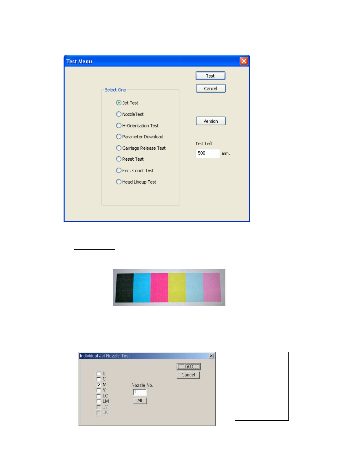
11.3.1. Jet Test:
See chapter “8.2. Daily Maintenance – Nozzle check/purge”
11.3.2. Nozzle Test:
This allows you to test 1 nozzle of a particular head.
The requested nozzle is printed in a straight line.
AB]]]]]]]]]]]]]]]]]]]]]]]]]]]]]]]]]]]]]]]]]]]]]]]]]]]]]]]]]]]]]]]]]]]]]]]]]]]]]]]]]]]]]]]]]]]]]]]]]]]]]]]]]]]]]]]]]]]]]]]]]]]]]]]]]]]]]]]]]]]]]]]]]]]]]]]]]]]]]]]]]]]]]]]]]]]]]]]]]]]]]]]]]]]]]]]]]]]]]]]]]]]]]]]]]]]]]]]]]]]]]]]]]]]]46]
8/08/2008
]
Page 47

:ANAPURNA XL² OPERATOR MANUAL
Do
NOT to push
or pull
on the UV
-
lamps.
11.3.3. H-Orientation Test:
This test is used to align all the heads, in reference to the Black head, both
horizontal and perpendicular.
When the engine is installed, or a print head has been exchanged, this test is
carried out by a technician.
11.3.4. Parameter Download:
After you’ve changed a parameter in the Setup file, which was marked with an
“ ”, use this feature to validate those new values.
11.3.5. Carriage Release Test:
This feature is mainly intended for a Service engineer, it allows the release of the
Carriage motor, which is normally anchored on both side’s.
After executing, it’s possible to move the Carriage by hand from right to left.
ONLY push on the back of the carriage!
IMPORTANT: To end this test, select “Reset Test” in the same menu, the
Carriage will move slowly back to the Home position.
11.3.6. Reset Test:
This will Reset the printer.
11.3.7. Enc. Count Test:
This test will measure the Encoder pulse.
AB]]]]]]]]]]]]]]]]]]]]]]]]]]]]]]]]]]]]]]]]]]]]]]]]]]]]]]]]]]]]]]]]]]]]]]]]]]]]]]]]]]]]]]]]]]]]]]]]]]]]]]]]]]]]]]]]]]]]]]]]]]]]]]]]]]]]]]]]]]]]]]]]]]]]]]]]]]]]]]]]]]]]]]]]]]]]]]]]]]]]]]]]]]]]]]]]]]]]]]]]]]]]]]]]]]]]]]]]]]]]]]]]]]]]47]
8/08/2008
]
Page 48

:ANAPURNA XL² OPERATOR MANUAL
11.3.8. Head LineUp test:
This test is used to align the slant of the heads, and should not be used by a user.
When the engine is installed, or a print head has been exchanged, this test is
carried out by a technician.
12
12.
. Print
1212
Printing an image
. .
PrintPrint
ing an image....
ing an imageing an image
12.1. Preparing an image
First you need to install and configure the Wasatch RIP.
(Read the Wasatch Manual on how to)
Configure the “output” folder in Wasatch to “c:\rtl” on the Anapurna PC.
Now you need to prepare the image file in the Wasatch RIP.
(Read the Wasatch Manual on how to)
At the RIP level, you’ll already need to determine, the # of passes (speed) you
want the image to be printed out at, later on the Anapurna.
If you should RIP an image for a 6 pass output, and on the Anapurna, you print it
at 8 pass, it will result in an un-proportionally scaled printout.
12.2. Preparing the :Anapurna
1) The carriage must be moved to the home position first.
Always make sure there is NO media or obstructions on the conveyor belt
when you move the carriage to the home position.
2) Place/load the media (rigid/flexible) onto the front side of the belt,
turn on the vacuum. (white lamp on tower => vacuum is on)
3) Check that you are using the correct setup file (textbox in lower left corner
of the ‘Setup’ menu shows you the loaded setup file; If a new setup file is
loaded, don’t forget to do a ‘parameter download’ to activate the loaded
parameters into the machine.
4) Perform a Set Gap. (See chapter 10); Make sure that the sensor senses on top
of your media.
5) Perform a Jet Test:
Place an A4 size paper, onto your media, or if you’ve loaded a flexible media,
you can immediately do it on that surface. (See chapter 8.1)
6) Position your rigid media, by means of the register pins on the backside.
(blue light on tower => register pins are down)
If you have loaded a flexible media, it’s still present from step 2.
7) The :Anapurna is now ready for printing.
AB]]]]]]]]]]]]]]]]]]]]]]]]]]]]]]]]]]]]]]]]]]]]]]]]]]]]]]]]]]]]]]]]]]]]]]]]]]]]]]]]]]]]]]]]]]]]]]]]]]]]]]]]]]]]]]]]]]]]]]]]]]]]]]]]]]]]]]]]]]]]]]]]]]]]]]]]]]]]]]]]]]]]]]]]]]]]]]]]]]]]]]]]]]]]]]]]]]]]]]]]]]]]]]]]]]]]]]]]]]]]]]]]]]]]48]
8/08/2008
]
Page 49

:ANAPURNA XL² OPERATOR MANUAL
12.3. Printing the image
1) In the :Anapurna Control Program, OPEN the image file (.rtl) that is sent over
from the RIP.
2) Check the Image Size, and set the Print Mode to the correct # passes.
(check Status Message: e.g.: 8 pass Ready)
3) Set the Top- and Left- Margin according your desired placement.
(See chapter 9.1.3 and 9.2.2.2)
4) Choose between Uni- or Bi-directional printing.
5) Switch on the UV lamps. (See chapter 6.)
6) As soon as the “green” lamp comes up on the tower, you can press
the PRINT button. (green lamp on tower => UV lamps are ready)
AB]]]]]]]]]]]]]]]]]]]]]]]]]]]]]]]]]]]]]]]]]]]]]]]]]]]]]]]]]]]]]]]]]]]]]]]]]]]]]]]]]]]]]]]]]]]]]]]]]]]]]]]]]]]]]]]]]]]]]]]]]]]]]]]]]]]]]]]]]]]]]]]]]]]]]]]]]]]]]]]]]]]]]]]]]]]]]]]]]]]]]]]]]]]]]]]]]]]]]]]]]]]]]]]]]]]]]]]]]]]]]]]]]]]]49]
8/08/2008
]
Page 50

:ANAPURNA XL² OPERATOR MANUAL
12.4. Cancel a print
While printing, press “S” and “Y”, the print is then cancelled.
12.5. Purge function on the printing
While printing, press “S” and “N”, at ‘Purge Request?’ select “Y”, the carriage will
move to the Purge position. After the Purge intervention, press the “OK” button to
continue printing.
AB]]]]]]]]]]]]]]]]]]]]]]]]]]]]]]]]]]]]]]]]]]]]]]]]]]]]]]]]]]]]]]]]]]]]]]]]]]]]]]]]]]]]]]]]]]]]]]]]]]]]]]]]]]]]]]]]]]]]]]]]]]]]]]]]]]]]]]]]]]]]]]]]]]]]]]]]]]]]]]]]]]]]]]]]]]]]]]]]]]]]]]]]]]]]]]]]]]]]]]]]]]]]]]]]]]]]]]]]]]]]]]]]]]]]50]
8/08/2008
]
Page 51

:ANAPURNA XL² OPERATOR MANUAL
13
13.
. Tips & Tricks
1313
Tips & Tricks....
. .
Tips & TricksTips & Tricks
13.1. Printing on heat sensitive media:
When printing on heat sensitive media, media can come upwards (head strikes)
but also expands in width when it is heated up by passing UV-lamps.
This can not only cause head strikes, but due to the expansion during print, the
different print passes will not align properly with earlier printed passes. This will
mostly be visible as lighter zones (spots) at the edges of your media (in both
directions).
In these cases you need to minimize the amount of heat that reaches your media,
by following guidelines:
- Print Uni-directional. This works on different aspects together and is most
likely the best solution:
o The left UV-lamp can be turned off (50% less heat)
o After each pass, the media can cool down again during the return pass
o No bidirectional printing means also less susceptible to visible
artefacts due to media expansion.
o Print Quality improvement
- Use only half power on the UV-lamps, if the ink is still enough cured.
- Make sure the carriage moves over the left media edge, on point of return (use
a white trailer in Wasatch at the right side of your image).
- for rigid media: put a rigid of the same height in front and behind the media;
That way you avoid that open air holes at the start and the end of the plate
will make the vacuum lower and allow the media to move during expansion by
heat.
If this is not sufficient or not wanted, following actions can be done:
- Rip and print your image in a lower number of passes; This will reduce the
number of times that a lamp passes the media.
- Select a higher shuttle speed; It will not always be possible, and influences
certainly the print quality.
- Set a head height of 2 to 2.5mm. (Adjust the Bi-dir alignment if printed
bidirectional); Print quality will get lower.
- For smaller media : place the media at the 2nd register pins (left side), so
you’ll allow the surface to cool down more in between the longer print pass.
- On very small media: mask the conveyor belt area around the media, ensuring
a stronger local vacuum. (Use sheets of paper) .
- Use a leading white border of 15 cm in Wasatch in front of the real image
data. This will take you a few extra printing passes but this will take care that
the border of your media is already heated up steadily per moving pass and
conditioned (extended) against the time that the first drops are jetted onto it.
AB]]]]]]]]]]]]]]]]]]]]]]]]]]]]]]]]]]]]]]]]]]]]]]]]]]]]]]]]]]]]]]]]]]]]]]]]]]]]]]]]]]]]]]]]]]]]]]]]]]]]]]]]]]]]]]]]]]]]]]]]]]]]]]]]]]]]]]]]]]]]]]]]]]]]]]]]]]]]]]]]]]]]]]]]]]]]]]]]]]]]]]]]]]]]]]]]]]]]]]]]]]]]]]]]]]]]]]]]]]]]]]]]]]]]51]
8/08/2008
]
Page 52

:ANAPURNA XL² OPERATOR MANUAL
13.2. Media corners lift a bit up (rigid media):
- Place another piece of rigid media (same height or lower) in front of the loaded
rigid. This will ensure a stronger vacuum on the front corners.
- Move the substrate to another left margin position so that you will cover with
the media plate as little as possible air-compartments of your vacuum table;
The not-used vacuum compartments can then be fully closed with the
corresponding valve, leaving more vacuum for the used compartments.
- Avoid that a media edge is laying down on the separation line between 2
neighboring vacuum compartments; In this zone of about 8 cm, you have less
vacuum available.
13.3. Image size/border: (Wasatch Rip)
By default, when you install the Wasatch Rip, there is an EPS-border active.
This will put a border of 2.54cm around every new opened image.
This will make borderless image printing very difficult, in terms of placement.
In Wasatch RIP; select OPTIONS, Set EPS Border….and set the value to “0”.
13.4. Positioning of media and use of the vacuum valves
The vacuum table is divided in 4 inner compartments; The table width is 254 cm, so
each compartment is about 63.5 cm. The borders of these compartments are marked
with a yellow bullet onto the beam bar, and the compartments are numbered from
home to purge in sequence V1 until V4.
When positioning the media, it is important to lay down the media symmetrical to the
compartments, and completely cover as much compartments as possible.
Try to avoid that the media edge is laying down in the separation line between 2
compartments (less vacuum on that place).
Only that way, a reliable transport is possible.
Also the valves at the rear of the engine have to be set accordingly:
- set the valve of a completely covered compartment to 20°
- set the valve of a partly covered compartment to 90° (=full power)
- set the valve of a not used compartment to 0° (=closed)
- if 2 neighbor compartments are closed: leave that ring blower OFF
Without doing this, the vacuum in a fully covered area is much higher than on the half
covered area, with as result that the media will show ‘a smiley’ onto the rear end of
the vacuum table, and this can lead to head crashes and not straight media transport.
AB]]]]]]]]]]]]]]]]]]]]]]]]]]]]]]]]]]]]]]]]]]]]]]]]]]]]]]]]]]]]]]]]]]]]]]]]]]]]]]]]]]]]]]]]]]]]]]]]]]]]]]]]]]]]]]]]]]]]]]]]]]]]]]]]]]]]]]]]]]]]]]]]]]]]]]]]]]]]]]]]]]]]]]]]]]]]]]]]]]]]]]]]]]]]]]]]]]]]]]]]]]]]]]]]]]]]]]]]]]]]]]]]]]]]52]
8/08/2008
]
Page 53

:ANAPURNA XL² OPERATOR MANUAL
V4 V3 V2 V1
Table
Front roller
MEDIA
V4 V3 V2 V1
Table
MEDIA
Some examples:
Media width = 152 cm (cover 2 compartments completely since 152 > 63.5+63.5)
Rear roller
Front roller
Valve Position:
V4=90° V3=20° V2=20° V1=90°
Media width = 90 cm (covers only 1 compartment completely)
Rear roller
Valve Position:
V4=0° V3=90° V2=20° V1=90°
AB]]]]]]]]]]]]]]]]]]]]]]]]]]]]]]]]]]]]]]]]]]]]]]]]]]]]]]]]]]]]]]]]]]]]]]]]]]]]]]]]]]]]]]]]]]]]]]]]]]]]]]]]]]]]]]]]]]]]]]]]]]]]]]]]]]]]]]]]]]]]]]]]]]]]]]]]]]]]]]]]]]]]]]]]]]]]]]]]]]]]]]]]]]]]]]]]]]]]]]]]]]]]]]]]]]]]]]]]]]]]]]]]]]]]53]
8/08/2008
]
Page 54

:ANAPURNA XL² OPERATOR MANUAL
Table
Rear roller
MEDIA
V4 V3 V2 V1
Table
Front roller
MEDIA
V4 V3 V2 V1
Table
Front roller
Media width = 50 cm (covers no compartment completely)
Rear roller
Valve Position:
V4=off V3=off V2=0° V1=90°
Media width = 230 cm (covers 2 compartment completely)
Rear roller
Valve Position:
V4=90° V3=20° V2=20° V1=90°
Media width = 250 cm (covers 4 compartment completely)
V4 V3 V2 V1
Front roller
Valve Position:
V4=30° V3=30° V2=30° V1=30°
AB]]]]]]]]]]]]]]]]]]]]]]]]]]]]]]]]]]]]]]]]]]]]]]]]]]]]]]]]]]]]]]]]]]]]]]]]]]]]]]]]]]]]]]]]]]]]]]]]]]]]]]]]]]]]]]]]]]]]]]]]]]]]]]]]]]]]]]]]]]]]]]]]]]]]]]]]]]]]]]]]]]]]]]]]]]]]]]]]]]]]]]]]]]]]]]]]]]]]]]]]]]]]]]]]]]]]]]]]]]]]]]]]]]]]54]
8/08/2008
]
 Loading...