

Page 1
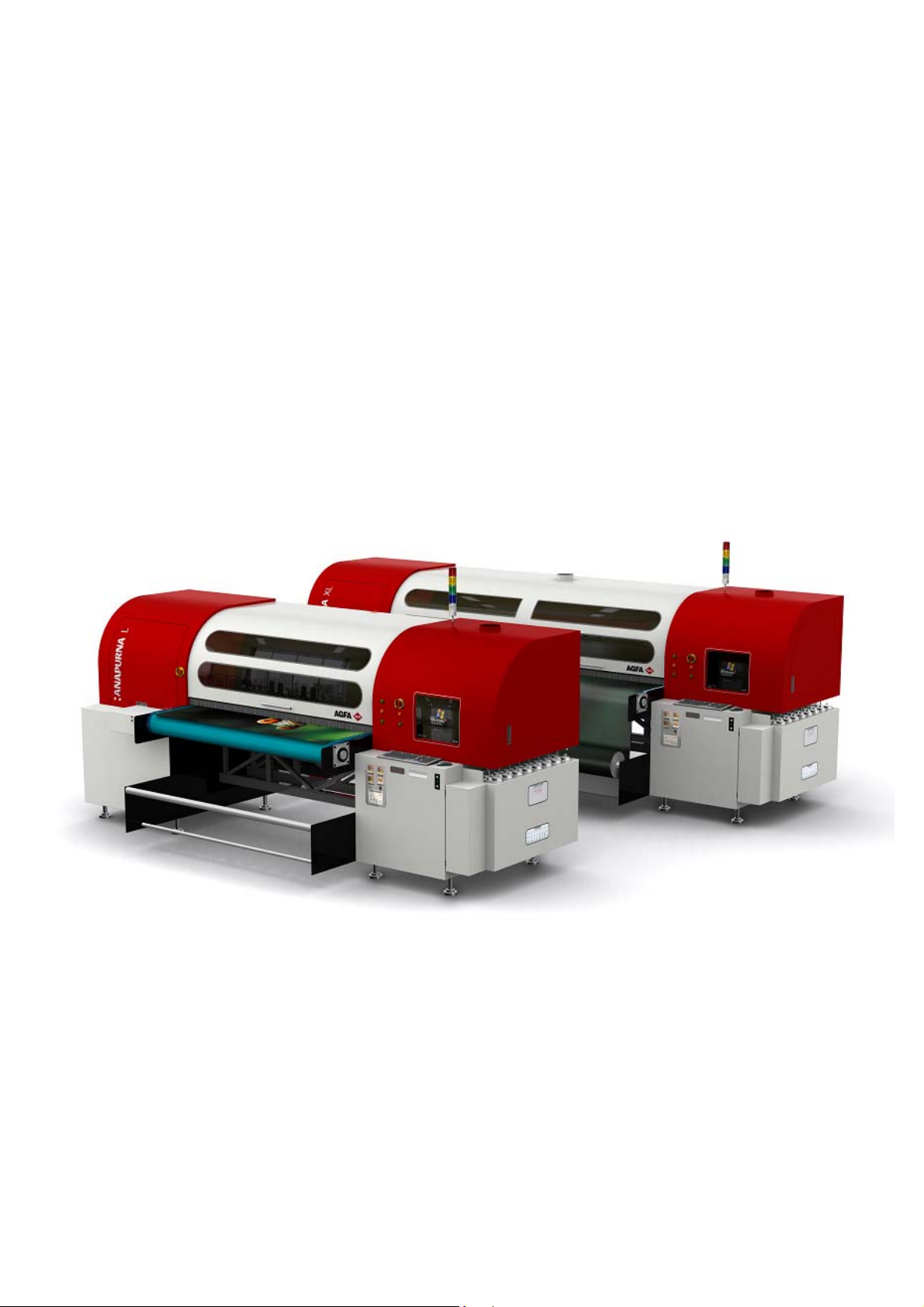
:ANAPURNA L/XL
OPERATOR MANUAL
Version 1.0
AB]
Page 2

:ANAPURNA L/XL OPERATOR MANUAL
TABLE OF CONTENTS
1. Safety Instructions ..................................................................................................................................................................... 3
2. Printer Overview and Features................................................................................................................................................. 4
2.1 Front view, parts & locations ........................................................................................................................................ 5
2.2 Rear view, parts & locations.......................................................................................................................................... 5
2.3 Head Carriage view, parts.............................................................................................................................................. 7
2.4 Signal tower ..................................................................................................................................................................... 7
3. Head Technology ........................................................................................................................................................................ 8
4. :Anapurna UV Curable Ink......................................................................................................................................................... 9
4.1 General information ........................................................................................................................................................ 9
4.2 Color gamut...................................................................................................................................................................... 9
4.3 Packing.............................................................................................................................................................................. 9
5. Ink Circuit ................................................................................................................................................................................. 10
5.1 Main ink tanks .............................................................................................................................................................. 10
5.2 Auto ink supply............................................................................................................................................................. 10
5.3 Sub Ink Tank.................................................................................................................................................................. 10
5.4 The 2-way valves.......................................................................................................................................................... 12
5.5 Printing heads............................................................................................................................................................... 13
5.6. Ink Refill System ......................................................................................................................................................... 15
5.7 Waste tank..................................................................................................................................................................... 15
6. UV Curing System.................................................................................................................................................................... 16
6.1 General information ..................................................................................................................................................... 16
6.2 Curing setup and sequences ...................................................................................................................................... 16
6.3 Uni- and Bi-directional printing................................................................................................................................. 17
7. Printing Table........................................................................................................................................................................... 18
7.1 General information ..................................................................................................................................................... 18
7.2 Belt Tension control..................................................................................................................................................... 18
7.3 Maintenance.................................................................................................................................................................. 19
7.4 Replacement ................................................................................................................................................................. 19
8. Maintenance............................................................................................................................................................................. 20
8.1 General information ..................................................................................................................................................... 20
8.2 Daily Maintenance – Nozzle check/purge.............................................................................................................. 20
8.3 Weekly Maintenance................................................................................................................................................... 23
8.4 Long Stand Still............................................................................................................................................................. 24
9. Media Setup ............................................................................................................................................................................. 26
9.1 Roll to Roll..................................................................................................................................................................... 26
9.2 Rigid Media.................................................................................................................................................................... 28
9.3 Media Roller Bars ......................................................................................................................................................... 29
10. Head Base – Height Control................................................................................................................................................ 30
10.1 Automatic “Head Base Height” Setup.................................................................................................................... 30
11. :Anapurna Control Program................................................................................................................................................. 32
11.1 Control Program Menu.............................................................................................................................................. 32
11.2 Setup Parameter Menu ............................................................................................................................................. 33
11.3 Test Menu.................................................................................................................................................................... 37
12. Printing an image.................................................................................................................................................................. 39
12.1 Preparing an image.................................................................................................................................................... 39
12.2 Preparing the :Anapurna........................................................................................................................................... 39
12.3. Printing the image .................................................................................................................................................... 40
12.4. Cancel a print............................................................................................................................................................. 41
12.5. Purge function on the printing ............................................................................................................................... 41
13. Tips & Tricks........................................................................................................................................................................... 42
AB]]]]]]]]]]]]]]]]]]]]]]]]]]]]]]]]]]]]]]]]]]]]]]]]]]]]]]]]]]]]]]]]]]]]]]]]]]]]]]]]]]]]]]]]]]]]]]]]]]]]]]]]]]]]]]]]]]]]]]]]]]]]]]]]]]]]]]]]]]]]]]]]]]]]]]]]]]]]]]]]]]]]]]]]]]]]]]]]]]]]]]]]]]]]]]]]]]]]]]]]]]]]]]]]]]]]]]]]]]]]]]]]]]]]2] 8/09/2006]
Page 3

:ANAPURNA L/XL OPERATOR MANUAL
1. Safety Instructions.
Be sure to follow all instructions and warnings in this manual when using
Do NOT look directly into the UV light when printing, and don’t expose
your skin directly to the UV light. If you need to look at the direction of the
light, wear protective glasses or look through the front cover glas.
UV ink contains chemicals, when handling the ink, wear protective gloves
to protect your skin, and protective glasses. Should the ink come in
contact with your skin, wash with water immediately.
The Anapurna engines are equipped with an exhaust system to extract the
heat and the ozone gas, which is built up by the curing process.
Make sure the exhaust system leads to the outside air.
IMPORTANT
the equipment.
WARNING
WARNING
IMPORTANT
AB]]]]]]]]]]]]]]]]]]]]]]]]]]]]]]]]]]]]]]]]]]]]]]]]]]]]]]]]]]]]]]]]]]]]]]]]]]]]]]]]]]]]]]]]]]]]]]]]]]]]]]]]]]]]]]]]]]]]]]]]]]]]]]]]]]]]]]]]]]]]]]]]]]]]]]]]]]]]]]]]]]]]]]]]]]]]]]]]]]]]]]]]]]]]]]]]]]]]]]]]]]]]]]]]]]]]]]]]]]]]]]]]]]]]3] 8/09/2006]
Page 4
:ANAPURNA L/XL OPERATOR MANUAL
2. Printer Overview and Features.
System Dimensions:
ANAPURNA XL
ANAPURNA L
AB]]]]]]]]]]]]]]]]]]]]]]]]]]]]]]]]]]]]]]]]]]]]]]]]]]]]]]]]]]]]]]]]]]]]]]]]]]]]]]]]]]]]]]]]]]]]]]]]]]]]]]]]]]]]]]]]]]]]]]]]]]]]]]]]]]]]]]]]]]]]]]]]]]]]]]]]]]]]]]]]]]]]]]]]]]]]]]]]]]]]]]]]]]]]]]]]]]]]]]]]]]]]]]]]]]]]]]]]]]]]]]]]]]]]4] 8/09/2006]
Max. media width: 2.5m (printable width: 2.48m)
Max. media width: 1.6m (printable width: 1.58m)
Page 5

:ANAPURNA L/XL OPERATOR MANUAL
2.1. Front view, parts & locations
2.2. Rear view, parts & locations
AB]]]]]]]]]]]]]]]]]]]]]]]]]]]]]]]]]]]]]]]]]]]]]]]]]]]]]]]]]]]]]]]]]]]]]]]]]]]]]]]]]]]]]]]]]]]]]]]]]]]]]]]]]]]]]]]]]]]]]]]]]]]]]]]]]]]]]]]]]]]]]]]]]]]]]]]]]]]]]]]]]]]]]]]]]]]]]]]]]]]]]]]]]]]]]]]]]]]]]]]]]]]]]]]]]]]]]]]]]]]]]]]]]]]]5] 8/09/2006]
Page 6

:ANAPURNA L/XL OPERATOR MANUAL
COVER “OPEN” SENSOR
This engine is equipped with a “safety sensor” on the Front and Rear cover.
Carrige movement and printing can only be done with covers closed.
.
1. When carriage is waiting:
When a cover is “open”, you will see the “door open error” on the screen, and the carriage
will not move to Home or Purge if requested.
2. During printing:
When you open the cover at this stage, the PRINT will be CANCELLED and the
UV lamp shutter will be closed automatically.
(Purge or Home)
OPENING THE COVER DURING PRINTING, WILL RESULT IN A CANCELLED PRINT !
ONLY OPEN THE DOOR IN EMERGENCY SITUATIONS !
AB]]]]]]]]]]]]]]]]]]]]]]]]]]]]]]]]]]]]]]]]]]]]]]]]]]]]]]]]]]]]]]]]]]]]]]]]]]]]]]]]]]]]]]]]]]]]]]]]]]]]]]]]]]]]]]]]]]]]]]]]]]]]]]]]]]]]]]]]]]]]]]]]]]]]]]]]]]]]]]]]]]]]]]]]]]]]]]]]]]]]]]]]]]]]]]]]]]]]]]]]]]]]]]]]]]]]]]]]]]]]]]]]]]]]6] 8/09/2006]
Page 7

:ANAPURNA L/XL OPERATOR MANUAL
2.3. Head Carriage view, parts
2.4. Signal tower
AB]]]]]]]]]]]]]]]]]]]]]]]]]]]]]]]]]]]]]]]]]]]]]]]]]]]]]]]]]]]]]]]]]]]]]]]]]]]]]]]]]]]]]]]]]]]]]]]]]]]]]]]]]]]]]]]]]]]]]]]]]]]]]]]]]]]]]]]]]]]]]]]]]]]]]]]]]]]]]]]]]]]]]]]]]]]]]]]]]]]]]]]]]]]]]]]]]]]]]]]]]]]]]]]]]]]]]]]]]]]]]]]]]]]]7] 8/09/2006]
Page 8

:ANAPURNA L/XL OPERATOR MANUAL
3. Head technology.
- Spectra Nova 256/80 AAA JA (Jetting Assembly)
• Calibrated Drop Size: 75 pl
• 256 addressable jetting nozzles, single line
• Nozzle spacing: 279 microns (0,011”)
• Intrinsic resolution: 91 dpi
- 8 JA mounted in head base plate
• 7 heads in line
• 1 head mounted in front of the other heads, used for “Pre-White”.
- Supported Color mode – fixed
- Color Sequence:
AB]]]]]]]]]]]]]]]]]]]]]]]]]]]]]]]]]]]]]]]]]]]]]]]]]]]]]]]]]]]]]]]]]]]]]]]]]]]]]]]]]]]]]]]]]]]]]]]]]]]]]]]]]]]]]]]]]]]]]]]]]]]]]]]]]]]]]]]]]]]]]]]]]]]]]]]]]]]]]]]]]]]]]]]]]]]]]]]]]]]]]]]]]]]]]]]]]]]]]]]]]]]]]]]]]]]]]]]]]]]]]]]]]]]]8] 8/09/2006]
Page 9

:ANAPURNA L/XL OPERATOR MANUAL
4. :Anapurna UV Curable Ink.
4.1. General information
- The :Anapurna UV curable ink is specially developed for
best performance on the :Anapurna engine.
- Sharp printing, vibrant colors on a wide range of media
- Ensures dry and instant ready prints with excellent outdoor durability
- Use of light inks
• Enhance apparent output resolution by using Light Cyan and
Light Magenta
• Results in smooth highlights
- Ink usage: ± 10ml/m², all colors together (6)
4.2. Color gamut
- Agfa Inks tuned towards the ISO Standard 12647 (2004)
- Calculated nr of colors (Volume calculated within Monaco CMS)
4.3. Packing
:Anapurna Cyan :Anapurna Magenta
:Anapurna Light Cyan :Anapurna Light Magenta
:Anapurna Yellow :Anapurna White
:Anapurna Black :Anapurna Cleaning Solution
AB]]]]]]]]]]]]]]]]]]]]]]]]]]]]]]]]]]]]]]]]]]]]]]]]]]]]]]]]]]]]]]]]]]]]]]]]]]]]]]]]]]]]]]]]]]]]]]]]]]]]]]]]]]]]]]]]]]]]]]]]]]]]]]]]]]]]]]]]]]]]]]]]]]]]]]]]]]]]]]]]]]]]]]]]]]]]]]]]]]]]]]]]]]]]]]]]]]]]]]]]]]]]]]]]]]]]]]]]]]]]]]]]]]]]9] 8/09/2006]
- ISO Standard 12647: 770.000 colors
- :Anapurna Ink on :Anapurna printing in:
» 6 pass : 830.000 colors
» 8 pass : 850.000 colors
» 12 pass : 1.080.000 colors
» 16 pass :
- 1L bottle, packed per 2
Page 10

:ANAPURNA L/XL OPERATOR MANUAL
5. Ink Circuit.
5.1. Main ink tanks
- The main ink tanks are located on the right
side of the engine.
- 1.6 liter per color
- Low level detection at 0.3l. (± 4h to print)
Audible & visual alarm on the Signal tower.
- Ink can be refilled in while printing
- White ink tank has a continuous working
stirring rod inside.
- Tanks:
At that point, you can pour in a complete 1L bottle, and you won’t have any
5.2. Auto ink supply
5.3. Sub Ink Tank
Color: 38°C
White Ink: 40°C when in use (up to max 45°C)
35°C when not in use
WARNING
ONLY refill with the 1liter bottle, when the low level alarm goes off.
left over ink remaining in the bottle!!
- From the ink tank, ink is pumped into
the “Sub ink tank”, which is positioned
on the Head Carriage.
- The Sub ink tank is temperature
controlled, and has a content
of 35ml per color
- Temperature setting “Sub Ink Tank”
AB]]]]]]]]]]]]]]]]]]]]]]]]]]]]]]]]]]]]]]]]]]]]]]]]]]]]]]]]]]]]]]]]]]]]]]]]]]]]]]]]]]]]]]]]]]]]]]]]]]]]]]]]]]]]]]]]]]]]]]]]]]]]]]]]]]]]]]]]]]]]]]]]]]]]]]]]]]]]]]]]]]]]]]]]]]]]]]]]]]]]]]]]]]]]]]]]]]]]]]]]]]]]]]]]]]]]]]]]]]]]]]]]]]]]10] 8/09/2006]
Page 11

:ANAPURNA L/XL OPERATOR MANUAL
- Read out:
- How to make changes:
At this stage, you also need to Press the “AT”
button, to close the procedure.
AB]]]]]]]]]]]]]]]]]]]]]]]]]]]]]]]]]]]]]]]]]]]]]]]]]]]]]]]]]]]]]]]]]]]]]]]]]]]]]]]]]]]]]]]]]]]]]]]]]]]]]]]]]]]]]]]]]]]]]]]]]]]]]]]]]]]]]]]]]]]]]]]]]]]]]]]]]]]]]]]]]]]]]]]]]]]]]]]]]]]]]]]]]]]]]]]]]]]]]]]]]]]]]]]]]]]]]]]]]]]]]]]]]]]]11] 8/09/2006]
Page 12
:ANAPURNA L/XL OPERATOR MANUAL
5.4. The 2-Way valves
- Normal printing:
- The color valves are positioned in the “I” direction.
The ink can flow to the head.
- Purging the heads:
- In case of clogged nozzles, or misfiring nozzles;
Push the “Purge” button at very short intervals,
this will cause ink flowing through the heads,
this will un-clog the missing nozzles.
(make sure the Grid is pushed to the back)
- Cleaning the heads with Cleaning solution:
- The color valves must be “closed”, set them to
the “S” direction. Now, the ink flow to the heads is closed.
Open the Cleaning Solution “control valve” on the right.
When you now push the “Solution-Purge” button on
the BACK of the shuttle, Cleaning solution will flow
through your heads to un-clog the missing nozzles.
THE APPROPRIATE WAY OF WORKING, FOR PERFORMING A NOZZLE CHECK,
CAN BE FOUND IN THE MAINTENANCE CHAPTER.
AND JUDGING MISFIRING NOZZLES,
AB]]]]]]]]]]]]]]]]]]]]]]]]]]]]]]]]]]]]]]]]]]]]]]]]]]]]]]]]]]]]]]]]]]]]]]]]]]]]]]]]]]]]]]]]]]]]]]]]]]]]]]]]]]]]]]]]]]]]]]]]]]]]]]]]]]]]]]]]]]]]]]]]]]]]]]]]]]]]]]]]]]]]]]]]]]]]]]]]]]]]]]]]]]]]]]]]]]]]]]]]]]]]]]]]]]]]]]]]]]]]]]]]]]]]12] 8/09/2006]
Page 13
:ANAPURNA L/XL OPERATOR MANUAL
5.5. Printing heads
- Ink supply by means of negative pressure:
By means of negative pressure, the ink is kept in the print heads.
A too high setting will cause missing nozzles, or no ink firing at all.
When the pressure is too low, the ink will leak out of the heads.
The Neg. Pressure should be set to -.0.34
The system will adjust the setting, when the
temperature on the Head Base plate is getting too high.
This is an automatic function, the customer will never
see a change on the display.
When using White ink:
It is possible that the Neg. Pressure needs to be tuned towards “-.036”, to
get a stable nozzle behavior for the White heads.
With the white ink, a higher temperature will result in a lower viscosity
(more liquid state), which can lead to ink “Pooling” underneath the print
head.
“Pooling”: ink build up underneath the print head, causing nozzle failure.
As the head needs to fire drops, the fired drops are not getting through the pool of
ink underneath the head. An increase of Neg. Pressure, (-.036) will bring the ink
more upwards into the meniscus of the print head, thus preventing the pooling.
- How to make changes:
Un-lock the black knob by pushing
the “A”-switch to the left.
You can now turn the black knob to
make changes in the pressure.
Push the “A” switch back to secure the knob.
AB]]]]]]]]]]]]]]]]]]]]]]]]]]]]]]]]]]]]]]]]]]]]]]]]]]]]]]]]]]]]]]]]]]]]]]]]]]]]]]]]]]]]]]]]]]]]]]]]]]]]]]]]]]]]]]]]]]]]]]]]]]]]]]]]]]]]]]]]]]]]]]]]]]]]]]]]]]]]]]]]]]]]]]]]]]]]]]]]]]]]]]]]]]]]]]]]]]]]]]]]]]]]]]]]]]]]]]]]]]]]]]]]]]]]13] 8/09/2006]
Page 14

:ANAPURNA L/XL OPERATOR MANUAL
- Head base temperature control:
Read-out on display:
- The upper value on the display, is the actual
temperature, the lower value is only an indication.
The actual temperature will not change if you
change that lower value.(***)
- The actual temperature needs to be 32°C when engine is not in use.
(cold engine)
- When printing, the temperature indication should not exceed 38°C.
- Make sure you print with closed engine doors all the time,
especially when room temperatures are 25°C and above.
This will give you the best cooling inside the engine.
In case the Head Base temperature reaches 40°C when printing:
At the end of your job, switch of the UV-lamps and run the “Encoder Test” for 5 minutes.
The carriage will now move continuously, allowing the Base Plate to cool down.
(The “Encoder Test” can be found in the TEST menu.)
(***) The temperature of the head base can only be tuned by changing the
“Head PCB Voltage” on the carriage. (1.55 Volt can be seen as guidance)
Changing the voltage is only allowed by a Service Engineer!
AB]]]]]]]]]]]]]]]]]]]]]]]]]]]]]]]]]]]]]]]]]]]]]]]]]]]]]]]]]]]]]]]]]]]]]]]]]]]]]]]]]]]]]]]]]]]]]]]]]]]]]]]]]]]]]]]]]]]]]]]]]]]]]]]]]]]]]]]]]]]]]]]]]]]]]]]]]]]]]]]]]]]]]]]]]]]]]]]]]]]]]]]]]]]]]]]]]]]]]]]]]]]]]]]]]]]]]]]]]]]]]]]]]]]]14] 8/09/2006]
Page 15

:ANAPURNA L/XL OPERATOR MANUAL
5.6. Ink Refill System
- Wrong ink in Main ink tank:
– what can go wrong…
Observed during ink-fill:
-
- Press emergency stop.
- Drain main tank, taps are situated behind a plate, under the Ink Tank Indicator.
- Rinse the main tank with cleaning solution, by using a squeeze bottle.
- Fill the ink tank again, and bleed the ink-filter
- The Ink filters are situated behind the Refill System panel
Loosen top cap (2) of filter
Push “Manual feeding” button
till ink drips out of top cap
Close top cap, tighten by hand
Observed during printing:
-
- The customer needs to call the Service Engineer
- “Empty” and “Feeding” led stay lighted ON:
Operator:
-
- Check the ink level in the tank visually
- Push the Manual Feed button
If the problem persists….
- Push emergency stop and restart the system
If the problem persists….
- Call the Service Engineer
5.7. Waste Tank
- When the waste tank is full, the blue lamp
will flash on the Signal tower, together with
a beep-alarm.
- The waste tank is located under the conveyor belt,
on the Purge-side of the engine.
Open the tap underneath to empty the tank.
- Make sure the UV-ink is kept separately from
solvent ink, do not mix them in a waste container.
AB]]]]]]]]]]]]]]]]]]]]]]]]]]]]]]]]]]]]]]]]]]]]]]]]]]]]]]]]]]]]]]]]]]]]]]]]]]]]]]]]]]]]]]]]]]]]]]]]]]]]]]]]]]]]]]]]]]]]]]]]]]]]]]]]]]]]]]]]]]]]]]]]]]]]]]]]]]]]]]]]]]]]]]]]]]]]]]]]]]]]]]]]]]]]]]]]]]]]]]]]]]]]]]]]]]]]]]]]]]]]]]]]]]]]15] 8/09/2006]
Page 16

:ANAPURNA L/XL OPERATOR MANUAL
6. UV Curing System.
6.1. General information
2 UV sources positioned in front of and behind head base plate
-
- High speed on-the-fly curing
- Curing power: 120 W/cm
- 2 fixed settings: Full and half strength
- Air cooled lamp-house
- Quick and easy replacement of the UV-bulbs
(Always change both the lamps !!)
- Expected lifetime ± 1000 hours
- Use of an automated shutter system
6.2. Curing setup and sequences
- Settings in software:
- Lamps continous ON (lamp stays “ON” for next print; longest lifetime)
- WarmUp Time (when turning back on the UV lamps, before ready state)
- Cooling Time (after turning off the UV lamps)
- Lamp Type: Cure (Default), Set or Both
AB]]]]]]]]]]]]]]]]]]]]]]]]]]]]]]]]]]]]]]]]]]]]]]]]]]]]]]]]]]]]]]]]]]]]]]]]]]]]]]]]]]]]]]]]]]]]]]]]]]]]]]]]]]]]]]]]]]]]]]]]]]]]]]]]]]]]]]]]]]]]]]]]]]]]]]]]]]]]]]]]]]]]]]]]]]]]]]]]]]]]]]]]]]]]]]]]]]]]]]]]]]]]]]]]]]]]]]]]]]]]]]]]]]]]16] 8/09/2006]
Page 17

:ANAPURNA L/XL OPERATOR MANUAL
6.3. Uni- and Bi-directional printing
- For Bi-directional printing, both UV lamps need to be used.
(curing is done on the fly in both printing directions)
- For Uni-directional printing, only the right UV lamp will be used.
(curing is only done when the shuttle is moving from right to left)
Depending on the heat-resistance/thickness of your media,
you can set the UV lamp power to “Half” or “Full” power.
By default, “Full” power should be used whenever possible.
When switching ON the UV-lamps, don’t switch them from “Off” to “Full”
power at once. Wait 2 seconds at “Half” power before switching them to
“Full“ power. Use the same procedure when going from Full power to Off.
AB]]]]]]]]]]]]]]]]]]]]]]]]]]]]]]]]]]]]]]]]]]]]]]]]]]]]]]]]]]]]]]]]]]]]]]]]]]]]]]]]]]]]]]]]]]]]]]]]]]]]]]]]]]]]]]]]]]]]]]]]]]]]]]]]]]]]]]]]]]]]]]]]]]]]]]]]]]]]]]]]]]]]]]]]]]]]]]]]]]]]]]]]]]]]]]]]]]]]]]]]]]]]]]]]]]]]]]]]]]]]]]]]]]]]17] 8/09/2006]
Page 18

:ANAPURNA L/XL OPERATOR MANUAL
7. Printing Table.
7.1. General information
- Woven Conveyor belt
- Transport is done by a step-motor
- On the table are 2 vacuum-zones with a fixed strength.
The table is evenly divided in a right (1) and a left (2) side,
which can be switched on in that order.
- When printing on a banner/paper type of roll media, only the right (1) vacuum
side should be used. (Even when the media width is almost the engine width)
- When printing on two rigid media, both vacuum tables must be used.
7.2. Belt Tension control
- 1) if the belt is touching the left or right guide, on the underside of the table.
- 2) remove the metal covers on the backside (both left and right), rotate the screw
at the REAR stand to CW or CCW to control the tension.
AB]]]]]]]]]]]]]]]]]]]]]]]]]]]]]]]]]]]]]]]]]]]]]]]]]]]]]]]]]]]]]]]]]]]]]]]]]]]]]]]]]]]]]]]]]]]]]]]]]]]]]]]]]]]]]]]]]]]]]]]]]]]]]]]]]]]]]]]]]]]]]]]]]]]]]]]]]]]]]]]]]]]]]]]]]]]]]]]]]]]]]]]]]]]]]]]]]]]]]]]]]]]]]]]]]]]]]]]]]]]]]]]]]]]]18] 8/09/2006]
Page 19

:ANAPURNA L/XL OPERATOR MANUAL
7.3. Maintenance
- Always make sure, when printing “borderless”, that the belt is masked,
so printing on the belt is reduced to a minimum.
- When you have printed onto the Conveyor belt, try to remove the ink with a
cleaning solution.
7.4. Replacement of Conveyor belt
- Vacuum can become insufficient when the belt is completely printed.
The Conveyor belt therefore is a Spare Part, and can be ordered as such.
AB]]]]]]]]]]]]]]]]]]]]]]]]]]]]]]]]]]]]]]]]]]]]]]]]]]]]]]]]]]]]]]]]]]]]]]]]]]]]]]]]]]]]]]]]]]]]]]]]]]]]]]]]]]]]]]]]]]]]]]]]]]]]]]]]]]]]]]]]]]]]]]]]]]]]]]]]]]]]]]]]]]]]]]]]]]]]]]]]]]]]]]]]]]]]]]]]]]]]]]]]]]]]]]]]]]]]]]]]]]]]]]]]]]]]19] 8/09/2006]
Page 20

:ANAPURNA L/XL OPERATOR MANUAL
8. Maintenance.
8.1. General information
- At the end of the day, and when you stop printing,
the shuttle needs to be placed in the
“Purge position”. For overnight or longer
standstill times, the “Grid” underneath the
shuttle must be pushed to the back.
- A default “Weeping” time is set in the engine
software to keep the heads open, this small amount of ink is collected in
the underneath waste box, which leads to a waste tank underneath the engine.
(See chapter 5.6, on how to empty)
- Place some towels in front of the Purge grid, this will help to
keep the area clean, it’s advisable to replace them weekly.
- The “Purge Grid” must be placed forward again when you start to print.
It prevents the ink in the underneath waste box from getting cured by the UV
lamps during the printing stage. It also prevents the UV lamps from curing the
ink onto the heads.
8.2. Daily Maintenance – Nozzle check/purge
- Check the state of the “Purge” and “Home” station Grid.
(Normally, only weekly cleaning is necessary)
- Perform a nozzle check and make sure all nozzles are firing.
- Move the head to the HOME position
- Place a white copy (A4-size) paper on
the printing table, if no media is present.
- Switch on the vacuum.
- In the Control program, push “Test”,
and select “Jet Test”.
- The Nozzle check will be printed
in-between the 4 white dots. (See picture)
The “red” area shows the placement of the
Spot- and Pré-white if it’s turned on.
(use a black or colored paper to see the white)
- Evaluate the nozzle check for missing nozzles.
The Jet Test must be carried out at a correct head height. Place the A4 paper
onto your media, or print it directly on a flexible media that is loaded and for
which the head height is adjusted.
AB]]]]]]]]]]]]]]]]]]]]]]]]]]]]]]]]]]]]]]]]]]]]]]]]]]]]]]]]]]]]]]]]]]]]]]]]]]]]]]]]]]]]]]]]]]]]]]]]]]]]]]]]]]]]]]]]]]]]]]]]]]]]]]]]]]]]]]]]]]]]]]]]]]]]]]]]]]]]]]]]]]]]]]]]]]]]]]]]]]]]]]]]]]]]]]]]]]]]]]]]]]]]]]]]]]]]]]]]]]]]]]]]]]]]20] 8/09/2006]
Page 21

:ANAPURNA L/XL OPERATOR MANUAL
- In case of nozzle failure:
Move carriage to PURGE position
Push the underneath GRID backwards
Little purge:
- Close all heads that are OK (switch them to the “S” position)
- Push the “Purge” button frequent, at very short intervals.
- Open all heads again (switch them back to the “I” position)
- Clean the heads with a fiber-free cloth. (*)
- Check on “weeping” (**)
by wiping from back to front on each head separately.
(Use backside of cloth, or a new cloth for every next head)
(*)Clean the heads with a fiber-free cloth,
(**) Hold a white A4-paper underneath the base plate to check the nozzles.
The intention is to capture the ink when the heads are weeping. (± 10sec)
You will see vertical lines appearing on the sheet, check them on interruption.
Large purge:
- With all the heads open….. (switch them all to the “I” position)
- Push and hold the “Purge” button for a longer time (2 sec.), end the procedure by
pushing the “Purge” button again, but now frequent, at very short intervals.
- Clean the heads with a fiber-free cloth. (*)
- Check on “weeping” (**)
IF NOZZLE FAILLURE STILL PERSISTS…. Proceed with following steps:
- Set the Neg. Pressure to “0”, leave the system for 1-2 minutes
(Ink will now start dripping out the heads)
- Restore the Neg. Pressure back to “-.034”
- Clean the heads with a fiber-free cloth.
- Check on “weeping” (**)
AB]]]]]]]]]]]]]]]]]]]]]]]]]]]]]]]]]]]]]]]]]]]]]]]]]]]]]]]]]]]]]]]]]]]]]]]]]]]]]]]]]]]]]]]]]]]]]]]]]]]]]]]]]]]]]]]]]]]]]]]]]]]]]]]]]]]]]]]]]]]]]]]]]]]]]]]]]]]]]]]]]]]]]]]]]]]]]]]]]]]]]]]]]]]]]]]]]]]]]]]]]]]]]]]]]]]]]]]]]]]]]]]]]]]]21] 8/09/2006]
Page 22

:ANAPURNA L/XL OPERATOR MANUAL
CLEANING the failing heads:
- Set the valves of the failing heads to the “S” position.
- Set the Solution valve to “S”.
- Push the “Solution-Purge” button on the back of the carriage.
(Keep pushing until you see a CLEAR “Solution-Curtain”
under the heads, then stop pushing)
Solution Valve
- Leave the heads in this condition for at least 5 minutes.
- Set the valves back to “I”.
- Set the Neg. Pressure to “0”, leave the system for 1 minute
(Ink will now start dripping out the heads)
- Restore the Neg. Pressure back to “-.034”
- Clean the heads with a fiber-free cloth.
- Check on “weeping” (**)
Solution-Curtain
When purging with “Cleaning-Solution”, always work the in three steps.
To clean all 8 heads, first purge the 4 right heads (Lc, Lm, W1, W2), close them,
and in the second stage, purge the remaining 4 left heads (K, C, M, Y).
Finally, open the 4 right heads again, and purge all 8 heads together now.
By doing so, you’ll have the most optimal cleaning pressure.
AB]]]]]]]]]]]]]]]]]]]]]]]]]]]]]]]]]]]]]]]]]]]]]]]]]]]]]]]]]]]]]]]]]]]]]]]]]]]]]]]]]]]]]]]]]]]]]]]]]]]]]]]]]]]]]]]]]]]]]]]]]]]]]]]]]]]]]]]]]]]]]]]]]]]]]]]]]]]]]]]]]]]]]]]]]]]]]]]]]]]]]]]]]]]]]]]]]]]]]]]]]]]]]]]]]]]]]]]]]]]]]]]]]]]]22] 8/09/2006]
Page 23

:ANAPURNA L/XL OPERATOR MANUAL
8.3. Weekly Maintenance
The weekly maintenance combines different small handlings, and a storage procedure:
- Clean the “Purge” and “Home” station Grid.
Use a filling-knife or a wide screwdriver, to cut off
the cured ink that’s on the ribs.
(the “Home” grid can be taken out to remove the particles)
- Check the Purge station waste box and clean it, if hardened ink is present.
- Check the waste ink tank underneath the printing
table; dispose the ink according to local government
regulations. (Also see chapter 5.6.)
- Clean the “encoder” strip with alcohol.
(Situated upfront on the main beam)
ENGINE STORAGE AT THE END OF THE WEEK:
- Move the carriage to the Purge position.
- Flush cleaning solution through the heads:
- First purge the 4 right heads (Lc, Lm, W1, W2), close them,
and in the second stage, purge the remaining 4 left heads (K, C, M, Y).
- Finally, open the 4 right heads again, and purge all 8 heads together now.
By doing so, you’ll have the most optimal cleaning pressure.
- Switch all heads, and the Solution valve back to “I”.
- Set the Neg. Vacuum Pressure to “0”, leave the system for 1 minute
(Ink will now start dripping out the heads)
- Empty the sub-airtank by opening the tap (use a tube into a PE-bottle)
(Sub-airtank is located at back of carriage)
- Restore the Neg. Pressure back to “-.034”
- Perform a Large Purge
- Clean the Head Base Plate with a cloth
- Clean the heads with a fiber-free cloth.
- Check the nozzle’s on “weeping” or with a Jet Test.
- If all nozzles are present, the engine can be left in the Purge Position,
with the Grid pushed backwards.
- Replace the towels in front of the Purge grid, and check/clean the whole Purge
station environment, the front of the UV-lamps might need some cleaning too.
- Clean the Quartz plate of both UV-lamp houses with alcohol. (underside of lamps)
ENCODER STRIP
SUB-AIRTANK
AB]]]]]]]]]]]]]]]]]]]]]]]]]]]]]]]]]]]]]]]]]]]]]]]]]]]]]]]]]]]]]]]]]]]]]]]]]]]]]]]]]]]]]]]]]]]]]]]]]]]]]]]]]]]]]]]]]]]]]]]]]]]]]]]]]]]]]]]]]]]]]]]]]]]]]]]]]]]]]]]]]]]]]]]]]]]]]]]]]]]]]]]]]]]]]]]]]]]]]]]]]]]]]]]]]]]]]]]]]]]]]]]]]]]]23] 8/09/2006]
Page 24

:ANAPURNA L/XL OPERATOR MANUAL
8.4. Long Stand Still
This procedure must be carried out:
- If the engine’s “Stand Still Time” is 1 week or longer…
- If the vacuum pressure is going to be closed down…
SHUTDOWN -- preparing the engine:
- Move the carriage to the Purge position.
- Flush cleaning solution through the heads:
- First purge the 4 right heads (Lc, Lm, W1, W2), close them,
and in the second stage, purge the remaining 4 left heads (K, C, M, Y).
- Finally, open the 4 right heads again, and purge all 8 heads together now.
By doing so, you’ll have the most optimal cleaning pressure.
- Leave all ink valves in the “S” position, set the Solution valve to “I”.
- On the Engine’s Control Panel, perform a “Head Lift-Up”.
(the carriage will go to the highest position)
- Clean the Head Base Plate with a cloth
- Set the Vacuum Pressure to “0”. (Negative Pressure)
- Mount the “Capping Plate” underneath the Head Base Plate.
- use a plastic foil to wrap around the capping plate (new foil every time)
- place a support between the capping plate and the grid.
- bring down the carriage by turning manually, until it’s fixed.
(use some packing material as support)
- Push the emergency stop, and leave it pushed in! (restart-safety)
Shut down the engine’s PC.
- Switch OFF the main power, by using the main-switch
in the engine’s fuse box.
- Turn off the compressed air.
- THE ENGINE IS NOW READY FOR A LONG STAND STILL -
MAIN SWITCH
AB]]]]]]]]]]]]]]]]]]]]]]]]]]]]]]]]]]]]]]]]]]]]]]]]]]]]]]]]]]]]]]]]]]]]]]]]]]]]]]]]]]]]]]]]]]]]]]]]]]]]]]]]]]]]]]]]]]]]]]]]]]]]]]]]]]]]]]]]]]]]]]]]]]]]]]]]]]]]]]]]]]]]]]]]]]]]]]]]]]]]]]]]]]]]]]]]]]]]]]]]]]]]]]]]]]]]]]]]]]]]]]]]]]]]24] 8/09/2006]
Page 25

:ANAPURNA L/XL OPERATOR MANUAL
STARTUP -- preparing the engine to print again:
- Remove the capping plate.
- Turn the compressed air back on. (still at “0” on display)
- Switch ON the main power switch in the engine’s fuse box.
- Pull the emergency stop back outwards.
- Startup the engine and switch the engine’s PC back on.
(ATTN.: carriage will move slowly to the Home position)
- Move the carriage back to the Purge position.
- Switch all ink valves back to “I”
- Perform a long purge, until you see ink appearing out of the heads.
- Let the ink drip for 1 minute
- Set the vacuum pressure back to “-.034”. (Negative Pressure)
- Clean the heads and base plate.
- Perform a nozzle check and purge again if necessary.
- THE ENGINE IS NOW READY TO PRINT AGAIN -
AB]]]]]]]]]]]]]]]]]]]]]]]]]]]]]]]]]]]]]]]]]]]]]]]]]]]]]]]]]]]]]]]]]]]]]]]]]]]]]]]]]]]]]]]]]]]]]]]]]]]]]]]]]]]]]]]]]]]]]]]]]]]]]]]]]]]]]]]]]]]]]]]]]]]]]]]]]]]]]]]]]]]]]]]]]]]]]]]]]]]]]]]]]]]]]]]]]]]]]]]]]]]]]]]]]]]]]]]]]]]]]]]]]]]]25] 8/09/2006]
Page 26

:ANAPURNA L/XL OPERATOR MANUAL
9. Media Setup.
9.1. Roll to Roll
9.1.1. Auto Feed System
The Auto feed system has two tension bars, holding a constant tension.
Those tension bars prevent distortion and waves on the media.
The Rear roll bar will unwind the media, with a constant tension and height
controlling. These are acquired from the “signal sensors”.
The Front roll bar will wind the printed media, holding a constant tension to reduce
distortion. Wind direction can be reversed.
Make sure you always insert the “Tension Roll Bar” at a correct way.
The ball bearing must be inside the guide.
When inserting, make sure both side’s are positioned as high as possible into
the left and right unit, then gently lower both sides, the bar must stay completely
horizontal for best use.
AB]]]]]]]]]]]]]]]]]]]]]]]]]]]]]]]]]]]]]]]]]]]]]]]]]]]]]]]]]]]]]]]]]]]]]]]]]]]]]]]]]]]]]]]]]]]]]]]]]]]]]]]]]]]]]]]]]]]]]]]]]]]]]]]]]]]]]]]]]]]]]]]]]]]]]]]]]]]]]]]]]]]]]]]]]]]]]]]]]]]]]]]]]]]]]]]]]]]]]]]]]]]]]]]]]]]]]]]]]]]]]]]]]]]]26] 8/09/2006]
Page 27

:ANAPURNA L/XL OPERATOR MANUAL
9.1.2. Take-up control system
(1) In Manual Mode, motor rotates CW
(2) In Manual Mode, motor rotates CCW
(1)+(2) You can RESET by pushing buttons for 1 sec
(3) - In Auto Mode: select motor direction (CW or CCW)
- In Manual Mode: select motor (Back or Front)
(4) Select Mode (Manual or Auto)
Take-Up Motor Box
9.1.3. Roll Alignment
When the roll media is loaded, measure the distance from the right
side (A) to the point where you want to start printing.
Enter this value on the engine’s Control Program, as a Left Margin.
9.1.4. Vacuum
For roll media, even at full engine width, you should only use vacuum table 1.
(for more info: see chapter 7.1)
AB]]]]]]]]]]]]]]]]]]]]]]]]]]]]]]]]]]]]]]]]]]]]]]]]]]]]]]]]]]]]]]]]]]]]]]]]]]]]]]]]]]]]]]]]]]]]]]]]]]]]]]]]]]]]]]]]]]]]]]]]]]]]]]]]]]]]]]]]]]]]]]]]]]]]]]]]]]]]]]]]]]]]]]]]]]]]]]]]]]]]]]]]]]]]]]]]]]]]]]]]]]]]]]]]]]]]]]]]]]]]]]]]]]]]27] 8/09/2006]
Page 28

:ANAPURNA L/XL OPERATOR MANUAL
9.2. Rigid Media
9.2.1. Rigid Support tables
- One table for use on the front, and one table for use on the back are delivered
with the machine. (Standard table; full engine width, and 1m long)
9.2.2. Rigid Alignment
9.2.2.1. Media Register Pins:
When turning the “Media Set” button once, all nr.1 pins will come down, allowing
you to load one rigid. This rigid can be small or at full engine width.
When you turn the button once more, the nr.2 pin will also come down, allowing
you to load two rigid media.
While performing those actions, the blue light will lighten up on the tower.
9.2.2.2. Top and Left Margin Setup:
The “A” and “B” positions, the “o-point”
at the corner of your media, are known distances.
The “A” point has a Top margin of 300 mm and 50 mm
as a Left Margin. These can be entered in the Control program.
Image placement for printing on two rigid media, must be done on Rip level.
AB]]]]]]]]]]]]]]]]]]]]]]]]]]]]]]]]]]]]]]]]]]]]]]]]]]]]]]]]]]]]]]]]]]]]]]]]]]]]]]]]]]]]]]]]]]]]]]]]]]]]]]]]]]]]]]]]]]]]]]]]]]]]]]]]]]]]]]]]]]]]]]]]]]]]]]]]]]]]]]]]]]]]]]]]]]]]]]]]]]]]]]]]]]]]]]]]]]]]]]]]]]]]]]]]]]]]]]]]]]]]]]]]]]]]28] 8/09/2006]
Page 29

:ANAPURNA L/XL OPERATOR MANUAL
Important
When printing on heat sensitive media, always make sure the right
UV lamp is going passed the media, on the point of returning.
(otherwise there will be more heat at the left side of the media,
which can cause media cockling or produce a yellowish shine on some media)
This can be arranged on the Rip level by entering a white space, and/or on
the engine, by changing the Left Margin distance.
9.2.3. Vacuum
With rigid media, the vacuum settings must be chosen according the covered area on
the conveyor belt. When printing on two rigid media, activate both the vacuum tables
(1&2). (more info: see chapter 7.1)
9.3. Media Roller Bars
The engine has got one roller bar on the front, and one on the back.
They are located underneath the front- and back-covers. These bars will help to keep
the media flat while it’s been transported on the conveyor belt.
It can be used on Roll media, as well as on rigid media.
You can lower the bars, by switching the “FRONT” or “REAR” buttons.
When you’ve taken out a bar, and want to re-insert it:
Make sure both side’s are positioned as high as possible into the left
and right unit, then gently lower both sides, the bar must stay completely
horizontal for best use.
AB]]]]]]]]]]]]]]]]]]]]]]]]]]]]]]]]]]]]]]]]]]]]]]]]]]]]]]]]]]]]]]]]]]]]]]]]]]]]]]]]]]]]]]]]]]]]]]]]]]]]]]]]]]]]]]]]]]]]]]]]]]]]]]]]]]]]]]]]]]]]]]]]]]]]]]]]]]]]]]]]]]]]]]]]]]]]]]]]]]]]]]]]]]]]]]]]]]]]]]]]]]]]]]]]]]]]]]]]]]]]]]]]]]]]29] 8/09/2006]
Page 30

:ANAPURNA L/XL OPERATOR MANUAL
10. Head Base – Height Control.
10.1. Automatic “Head Base Height” Setup
This is done in the “Head Gap Control”, which can be found in the Setup Parameter
window.
Check or change the following Parameters to set the Head Base Height:
Gap:
Enter the value that you want the “Head Base” to be above the
media surface. (Recommended values: 1.5mm for Rigid media,
and 2mm for Roll media)
Check Distance
Enter the Distance, from the Home position, where the “Set Gap” must
be executed. (This must be the HIGHEST point on your media)
Reference
This is the point where the “Head Base” will wait for an on-screen
confirmation, before going down to set the desired “Gap”.
Always make sure the SHUTTLE is positioned in the HOME position,
when you perform the “Set Gap” procedure.
:
:
Important
AB]]]]]]]]]]]]]]]]]]]]]]]]]]]]]]]]]]]]]]]]]]]]]]]]]]]]]]]]]]]]]]]]]]]]]]]]]]]]]]]]]]]]]]]]]]]]]]]]]]]]]]]]]]]]]]]]]]]]]]]]]]]]]]]]]]]]]]]]]]]]]]]]]]]]]]]]]]]]]]]]]]]]]]]]]]]]]]]]]]]]]]]]]]]]]]]]]]]]]]]]]]]]]]]]]]]]]]]]]]]]]]]]]]]]30] 8/09/2006]
Page 31

:ANAPURNA L/XL OPERATOR MANUAL
When all parameters are Ok, load the media onto the table, click on the “Set Gap”
Procedure : When you’ve entered a “2mm Gap” & “Check Distance: 800mm”
- The Head Base will stay in the Home position and go up to the highest
limit position (> 50mm).
- After this movement, you have to confirm on-screen that the carriage is
clear to move, to the “Check Distance” position.
- Shuttle will move 800mm to the left and come down to set the Gap.
- A sensor plate will become visible underneath the Head Base, to make
contact with the media surface.
- The Head Base will lower to his “Reference” point, and you’ll have
to confirm on-screen (Ready to Set Gap) to make the last fine-tuning. This
is lowering from the Reference point, to the desired Head Base Height (2
mm Gap)
- When this is done, you’ll get following message: “Check Gap and
Ready to Go to Home Position”. At this point, you can verify
the correct Gap setting with a measuring device.
Click on OK, and the Set Gap is completed.
AB]]]]]]]]]]]]]]]]]]]]]]]]]]]]]]]]]]]]]]]]]]]]]]]]]]]]]]]]]]]]]]]]]]]]]]]]]]]]]]]]]]]]]]]]]]]]]]]]]]]]]]]]]]]]]]]]]]]]]]]]]]]]]]]]]]]]]]]]]]]]]]]]]]]]]]]]]]]]]]]]]]]]]]]]]]]]]]]]]]]]]]]]]]]]]]]]]]]]]]]]]]]]]]]]]]]]]]]]]]]]]]]]]]]]31] 8/09/2006]
Page 32

:ANAPURNA L/XL OPERATOR MANUAL
11. :Anapurna Control Program.
11.1. Control Program Menu
The :Anapurna Control program on the engine’s PC:
1 : IMAGE display window
2 : IMAGE SIZE display window
3 : Move Carriage to “Purge” position
4 : Move Carriage to ‘Home” position
5 : Move loaded media Fwd/Back
6 : STATUS Message display window
7 : Display Printing Progress
8 : Set Top (forward) and Left Margin
(*) When you open an image file (.rtl), which is sent from the Rip station, you’ll get
an on-screen preview and it will also show the image size and nr. of passes the
image is ripped for. (if an image is ripped for 6 pass, and you print it at 8 pass, it
will result in an un-proportionally scaled printout)
(**) Regardless the image file, you can always choose between printing
Uni- or Bi-directional.
9 : Setup Menu, to Change Parameters
10 : Press to Open TEST menu
11 : Select PASS mode
12 : Push to start Printing
13 : Open image file(.rtl) to be printed (*)
14 : Lift head to highest position (>50mm)
15 : Select to Uni-Directional printing (**)
AB]]]]]]]]]]]]]]]]]]]]]]]]]]]]]]]]]]]]]]]]]]]]]]]]]]]]]]]]]]]]]]]]]]]]]]]]]]]]]]]]]]]]]]]]]]]]]]]]]]]]]]]]]]]]]]]]]]]]]]]]]]]]]]]]]]]]]]]]]]]]]]]]]]]]]]]]]]]]]]]]]]]]]]]]]]]]]]]]]]]]]]]]]]]]]]]]]]]]]]]]]]]]]]]]]]]]]]]]]]]]]]]]]]]]32] 8/09/2006]
Page 33

:ANAPURNA L/XL OPERATOR MANUAL
11.2. Setup Parameter Menu
General info: At first, you always have to OPEN a specific “.dat”-file, in which
all engine parameters are defined, such as the UV-settings,
Carriage speed, Bi-Dir alignment, Step size, etc.
The .dat-files are best named after the Carriage Speed and
head height. (e.g.: s-1250_2mm_flex.dat)
It’s best to make a new .dat –file for every different head height, also
make a different for flexible and rigid media.
11.2.1. Bi-Dir Alignment:
This only applies to Bi-directional printing!
You can change the value when you see that the drops are deviated from their
correct position. When printing Bi-di, the dots must be aligned and need to be
jetted to the same position, printing from right-to-left, and when printing from
left-to-right. A deviated Bi-Dir alignment will show as un-sharp text and blurry
images.
After changing a value: use the “Save as” button and create a
new .dat-file, or overwrite the old.
Changes on Parameters, marked with an “ ”,
require a “Parameter Download” in the TEST menu.
AB]]]]]]]]]]]]]]]]]]]]]]]]]]]]]]]]]]]]]]]]]]]]]]]]]]]]]]]]]]]]]]]]]]]]]]]]]]]]]]]]]]]]]]]]]]]]]]]]]]]]]]]]]]]]]]]]]]]]]]]]]]]]]]]]]]]]]]]]]]]]]]]]]]]]]]]]]]]]]]]]]]]]]]]]]]]]]]]]]]]]]]]]]]]]]]]]]]]]]]]]]]]]]]]]]]]]]]]]]]]]]]]]]]]]33] 8/09/2006]
Page 34

:ANAPURNA L/XL OPERATOR MANUAL
How to check the Bi-Dir Alignment:
Use a small image( 15cmx15cm), with text and a smooth background.
Evaluate the text sharpness and image smoothness.
As an indication, you can stop the print when it’s over half way.
By doing this, you’ll have a print with unfinished passes at the end, helping
you to evaluate the alignment.
The Bi-Dir can be out of focus, left or right:
Look at the end of the interrupted print:
(A) Too much left (B) GOOD (C) Too much right
Change the Bi-Dir Value Change the Bi-Dir Value
from e.g.: -4965 to -4980 from e.g.: -4965 to -4950
After changing, use “Save as”, and make a new .dat-file. (e.g.: s-1250_2mm_flex.dat)
In the TEST menu, select “Parameter Download”, the new value will be active.
AB]]]]]]]]]]]]]]]]]]]]]]]]]]]]]]]]]]]]]]]]]]]]]]]]]]]]]]]]]]]]]]]]]]]]]]]]]]]]]]]]]]]]]]]]]]]]]]]]]]]]]]]]]]]]]]]]]]]]]]]]]]]]]]]]]]]]]]]]]]]]]]]]]]]]]]]]]]]]]]]]]]]]]]]]]]]]]]]]]]]]]]]]]]]]]]]]]]]]]]]]]]]]]]]]]]]]]]]]]]]]]]]]]]]]34] 8/09/2006]
Page 35

:ANAPURNA L/XL OPERATOR MANUAL
11.2.2. Step Size:
The Step Size is also known as “Media Feed”.
You can visually see on a printed image if you have to adjust the Step Size.
(A) Dark lines in the print, as a result of overlapping passes.
Increase the Step Size value from:
e.g.: 51660 to 51680
(B) White lines in the print, as a result of a gap between the passes.
Decrease the Step Size value from:
e.g.: 51660 to 51640
After changing the value, use “Save as”, and overwrite the existing .dat-file.
In the TEST menu, select “Parameter Download”, click on TEST.
Now, the new value will be active.
11.2.3. Carriage Speed:
The engine has got 3 pre-defined Carriage speeds: 900, 1250 and 1525.
These
speeds are continuously variable. We consider 1250 as the default speed.
When printing Uni-directional with 1250, the printing speed is 1250, and the
returning speed (to home) is, by default set to 2000.
As a result, you don’t loose half your Bi-dir speed when printing Uni.
AB]]]]]]]]]]]]]]]]]]]]]]]]]]]]]]]]]]]]]]]]]]]]]]]]]]]]]]]]]]]]]]]]]]]]]]]]]]]]]]]]]]]]]]]]]]]]]]]]]]]]]]]]]]]]]]]]]]]]]]]]]]]]]]]]]]]]]]]]]]]]]]]]]]]]]]]]]]]]]]]]]]]]]]]]]]]]]]]]]]]]]]]]]]]]]]]]]]]]]]]]]]]]]]]]]]]]]]]]]]]]]]]]]]]]35] 8/09/2006]
Page 36

:ANAPURNA L/XL OPERATOR MANUAL
11.2.4. Feed Speed:
This is the forward speed of the conveyor belt between the print passes.
A Feed Speed of “500” is considered the default.
No changes have to be made, unless you print at a high speed/low pass,
and the conveyor belt is STILL feeding forward when the carriage already
started to print the next pass.
11.2.5. UV Options:
See chapter “6.2. Curing setup and sequences”, for detailed info.
11.2.6. Head Gap Control:
See chapter “10.1. Automatic “Head Base Height” Setup”, for detailed info.
11.2.7. Factory Set:
This button is password protected.
It can only be used by an Agfa trained technician.
11.2.8. Head Offset:
These are the Head alignment settings for each head, in reference to
the Black head. This alignment is done in advance by an engineer,
do NOT change these values!
AB]]]]]]]]]]]]]]]]]]]]]]]]]]]]]]]]]]]]]]]]]]]]]]]]]]]]]]]]]]]]]]]]]]]]]]]]]]]]]]]]]]]]]]]]]]]]]]]]]]]]]]]]]]]]]]]]]]]]]]]]]]]]]]]]]]]]]]]]]]]]]]]]]]]]]]]]]]]]]]]]]]]]]]]]]]]]]]]]]]]]]]]]]]]]]]]]]]]]]]]]]]]]]]]]]]]]]]]]]]]]]]]]]]]]36] 8/09/2006]
Page 37

:ANAPURNA L/XL OPERATOR MANUAL
11.3. Test Menu
11.3.1. Jet Test:
See chapter “8.2. Daily Maintenance – Nozzle check/purge”
11.3.2. Feed Step Test:
11.3.3. Nozzle Test:
This allows you to test 1 nozzle of a particular head.
The requested nozzle is printed in a straight line.
AB]]]]]]]]]]]]]]]]]]]]]]]]]]]]]]]]]]]]]]]]]]]]]]]]]]]]]]]]]]]]]]]]]]]]]]]]]]]]]]]]]]]]]]]]]]]]]]]]]]]]]]]]]]]]]]]]]]]]]]]]]]]]]]]]]]]]]]]]]]]]]]]]]]]]]]]]]]]]]]]]]]]]]]]]]]]]]]]]]]]]]]]]]]]]]]]]]]]]]]]]]]]]]]]]]]]]]]]]]]]]]]]]]]]]37] 8/09/2006]
Page 38

:ANAPURNA L/XL OPERATOR MANUAL
11.3.4. H-Orientation Test:
This test is used to align all the heads, in reference to the Black head, both
horizontal and perpendicular.
When the engine is installed, or a print head has been exchanged, this test is
carried out by a technician.
11.3.5. Parameter Download:
After you’ve changed a parameter in the Setup file, which was marked with an
“ ”, use this feature to validate those new values.
11.3.6. Carriage Release Test:
This feature is mainly intended for a Service engineer, it allows the release of the
Carriage motor, which is normally anchored on both side’s.
After executing, it’s possible to move the Carriage by hand from right to left.
Do NOT to push or pull on the UV-lamps.
ONLY push on the back of the carriage!
IMPORTANT: To end this test, select “Reset Test” in the same menu, the
Carriage will move slowly back to the Home position.
11.3.7. Reset Test:
This will Reset the printer.
11.3.8. Enc. Count Test:
This test will measure the Encoder pulse.
AB]]]]]]]]]]]]]]]]]]]]]]]]]]]]]]]]]]]]]]]]]]]]]]]]]]]]]]]]]]]]]]]]]]]]]]]]]]]]]]]]]]]]]]]]]]]]]]]]]]]]]]]]]]]]]]]]]]]]]]]]]]]]]]]]]]]]]]]]]]]]]]]]]]]]]]]]]]]]]]]]]]]]]]]]]]]]]]]]]]]]]]]]]]]]]]]]]]]]]]]]]]]]]]]]]]]]]]]]]]]]]]]]]]]]38] 8/09/2006]
Page 39

:ANAPURNA L/XL OPERATOR MANUAL
12. Printing an image.
12.1. Preparing an image
First you need to install and configure the Wasatch RIP.
(Read the Wasatch Manual on how to)
Configure the “output” folder in Wasatch to “c:\rtl” on the Anapurna PC.
Now you need to prepare the image file in the Wasatch RIP.
(Read the Wasatch Manual on how to)
At the RIP level, you’ll already need to determine, the # of passes (speed) you
want the image to be printed out at, later on the Anapurna.
If you should RIP an image for a 6 pass output, and on the Anapurna, you print it
at 8 pass, it will result in an un-proportionally scaled printout.
12.2. Preparing the :Anapurna
1) The carriage must be moved to the home position first.
Always make sure there is NO media or obstructions on the conveyor belt
when you move the carriage to the home position.
2) Place/load the media (rigid/flexible) onto the front side of the belt,
turn on the vacuum. (white lamp on tower => vacuum is on)
3) Load the correct setup file (e.g.: s-1250_2mm_flex.dat)
4) Perform a Set Gap. (See chapter 10)
5) Perform a Jet Test:
Place an A4 size paper, onto your media, or if you’ve loaded a flexible media,
you can immediately do it on that surface. (See chapter 8.1)
6) Position your rigid media, by means of the register pins on the backside.
(blue light on tower => register pins are down)
If you have loaded a flexible media, it’s still present from step 2.
7) The :Anapurna is now ready for printing.
AB]]]]]]]]]]]]]]]]]]]]]]]]]]]]]]]]]]]]]]]]]]]]]]]]]]]]]]]]]]]]]]]]]]]]]]]]]]]]]]]]]]]]]]]]]]]]]]]]]]]]]]]]]]]]]]]]]]]]]]]]]]]]]]]]]]]]]]]]]]]]]]]]]]]]]]]]]]]]]]]]]]]]]]]]]]]]]]]]]]]]]]]]]]]]]]]]]]]]]]]]]]]]]]]]]]]]]]]]]]]]]]]]]]]]39] 8/09/2006]
Page 40

:ANAPURNA L/XL OPERATOR MANUAL
12.3. Printing the image
1) In the :Anapurna Control Program, OPEN the image file (.rtl) that is sent over
from the RIP.
2) Check the Image Size, and set the Print Mode to the correct # passes.
(check Status Message: e.g.: 8 pass Ready)
3) Set the Top- and Left- Margin according your desired placement.
(See chapter 9.1.3 and 9.2.2.2)
4) Choose between Uni- or Bi-directional printing.
5) Switch on the UV lamps. (See chapter 6.)
6) As soon as the “green” lamp comes up on the tower, you can press
the PRINT button. (green lamp on tower => UV lamps are ready)
AB]]]]]]]]]]]]]]]]]]]]]]]]]]]]]]]]]]]]]]]]]]]]]]]]]]]]]]]]]]]]]]]]]]]]]]]]]]]]]]]]]]]]]]]]]]]]]]]]]]]]]]]]]]]]]]]]]]]]]]]]]]]]]]]]]]]]]]]]]]]]]]]]]]]]]]]]]]]]]]]]]]]]]]]]]]]]]]]]]]]]]]]]]]]]]]]]]]]]]]]]]]]]]]]]]]]]]]]]]]]]]]]]]]]]40] 8/09/2006]
Page 41

:ANAPURNA L/XL OPERATOR MANUAL
12.4. Cancel a print
While printing, press “S” and “Y”, the print is then cancelled.
12.5. Purge function on the printing
While printing, press “S” and “N”, at ‘Purge Request?’ select “Y”, the carriage will
move to the Purge position. After the Purge intervention, press the “OK” button to
continue printing.
AB]]]]]]]]]]]]]]]]]]]]]]]]]]]]]]]]]]]]]]]]]]]]]]]]]]]]]]]]]]]]]]]]]]]]]]]]]]]]]]]]]]]]]]]]]]]]]]]]]]]]]]]]]]]]]]]]]]]]]]]]]]]]]]]]]]]]]]]]]]]]]]]]]]]]]]]]]]]]]]]]]]]]]]]]]]]]]]]]]]]]]]]]]]]]]]]]]]]]]]]]]]]]]]]]]]]]]]]]]]]]]]]]]]]]41] 8/09/2006]
Page 42

:ANAPURNA L/XL OPERATOR MANUAL
13. Tips & Tricks.
13.1. Printing on heat sensitive media:
When printing on heat sensitive media, it’s sometimes difficult to ensure that the
media stays flat on the conveyor belt, to avoid head strikes.
If the head strikes the media, try to adapt by using following guidelines:
- Set a head height of 2 or 2.5mm. (Adjust the Bi-dir alignment if necessary)
- Use only half power on the UV-lamps.
- Make sure the carriage moves over the left media edge, on point of return.
- Print Uni-directional. (Also reduces 1/2 of your UV lamp heat)
- Place the media at the 2nd register pins (left side), so you’ll allow more
surface cooling down time.
- On very small media: mask the conveyor belt area around the media,
ensuring a stronger local vacuum. (Use sheets of paper)
13.2. Media corners lift a bit up (rigid media):
Place another piece of rigid media in front of the loaded rigid.
This will ensure a stronger vacuum on the front corners.
13.3. Image size/border: (Wasatch Rip)
By default, when you install the Wasatch Rip, there is an EPS-border active.
This will put a border of 2.54cm around every new opened image.
This will make borderless image printing very difficult, in terms of placement.
In Wasatch RIP; select OPTIONS, Set EPS Border….and set the value to “0”.
AB]]]]]]]]]]]]]]]]]]]]]]]]]]]]]]]]]]]]]]]]]]]]]]]]]]]]]]]]]]]]]]]]]]]]]]]]]]]]]]]]]]]]]]]]]]]]]]]]]]]]]]]]]]]]]]]]]]]]]]]]]]]]]]]]]]]]]]]]]]]]]]]]]]]]]]]]]]]]]]]]]]]]]]]]]]]]]]]]]]]]]]]]]]]]]]]]]]]]]]]]]]]]]]]]]]]]]]]]]]]]]]]]]]]]42] 8/09/2006]
 Loading...