

AEG-Electrolux EXCELLIOZ5140, EXD25DN3W, EXD15DN3W User Manual
Instructions
for the use and installation
of gas cookers
Notice d’emploi
pour l’installation et l’utilisation
des cuisinieres à gaz
GB
F

ATTENTION
This owner’s manual is valid for the Country mentioned
on the appliance.
Keep this manual close to hand and preserve it for any
further consultation.
The packing components (plastic bags, foamed polystyrene,
nails, etc...) are a source of potential risk; never leave them
within the reach of children.
If you use the grill keep the oven door half-open and the
grill deflector assembled as shown in the instructions booklet.
The glass cover (only on some models), before lighting the
over burners of the top and until their turning off, shall be
in open position; it is important to avoid any contact with
cookware during the cooking in order to save from a
dangerous overheating.
MODELS SPECIFICATIONS
2
a
1
a
100
C
1
C
2
B
2
a
1
a
100
Fig. 1
B
Important
After the cooker use it is recommended to:
1) always check that the knobs are in the “ ” position.
2) close the cock of the gas cylinder (if you use liquefied
gas) or the supply cock (in case of natural gas).
3) periodically check the wear of the hosepipe and replace
it if necessary. Do not repair it.
IMPORTANT:
The appliance must be installed only by qualified and
competent technicians in compliance with the national
provisions in force. Any modification that should be
necessary to the domestic system in order to install
the appliance shall be carried out by qualified technicians
only. The manufacturer declines all responsibility for
any damage caused by the non-observance of the rules
in force or due to an improper installation.
For any intervention please apply to an authorised aftersales
servicing centre and ask for original spare parts.
REMARK: during and after the use, the glass of the
oven door and accessible parts can be very hot; it is
therefore necessary to keep children away from the
appliance.
- Make sure that there is a regular air circulation around the
gas appliance. A poor ventilation reduces the oxygen.
In case of doubts consult the installer.
- The forming of fat or other food can start a fire. Carefully
mind the cooking with oils and fats.
- This appliance has been designed exclusively for the
cooking of food. Any other use (e.g. environment hating)
is considered improper and dangerous.
- Do not install the cooker near flammable material (e.g.
curtains, tea towels, etc...)
- Never clog the holes on the bottom of the oven. Do not
cover with aluminium sheets the oven walls, especially the
lower side.
- Always close the cock of gas supply before any cleaning
and maintenance operations.
- The oven parts in contact with food are made with materials
in compliance with the provisions of Directive EEC 89/109
dated 21/12/88.
- The cooker complies with the European Directives as to
gas EEC 90/395, EEC 93/88 and provisions EN 30-11 and
EN 2-1.
- Before operating on the unit remove the plastic films.
C
1
C
2
COOKER DIMENSIONS 80x50 80x50 90x60 90x60
AND CHARACTERISTICS with cylinder with cylinder
Height of top a1 85 ± 2 cm 85 ± 2 cm 85 ± 2 cm 85 ± 2 cm
Depth c1 51 cm 51 cm 60 cm 60 cm
Width B 80 cm 80 cm 90 cm 90 cm
Height of topof open lid a2 129 ± 2 cm 132 ± 2 cm 141 ± 2 cm 141 ± 2 cm
Depth with oven door open c2 88 cm 90 cm 98 cm 104 cm
Working capacity 44 dm
Class 1 1 2 subclass 1 2 subclass 1
Burners Burners adaptable for operation with LPG - natural gas
Operating voltage 220 Volt - 60 Hz
compartment compartment
3
74 dm
3
58 dm
3
135 dm
INSTRUCTION FOR USE
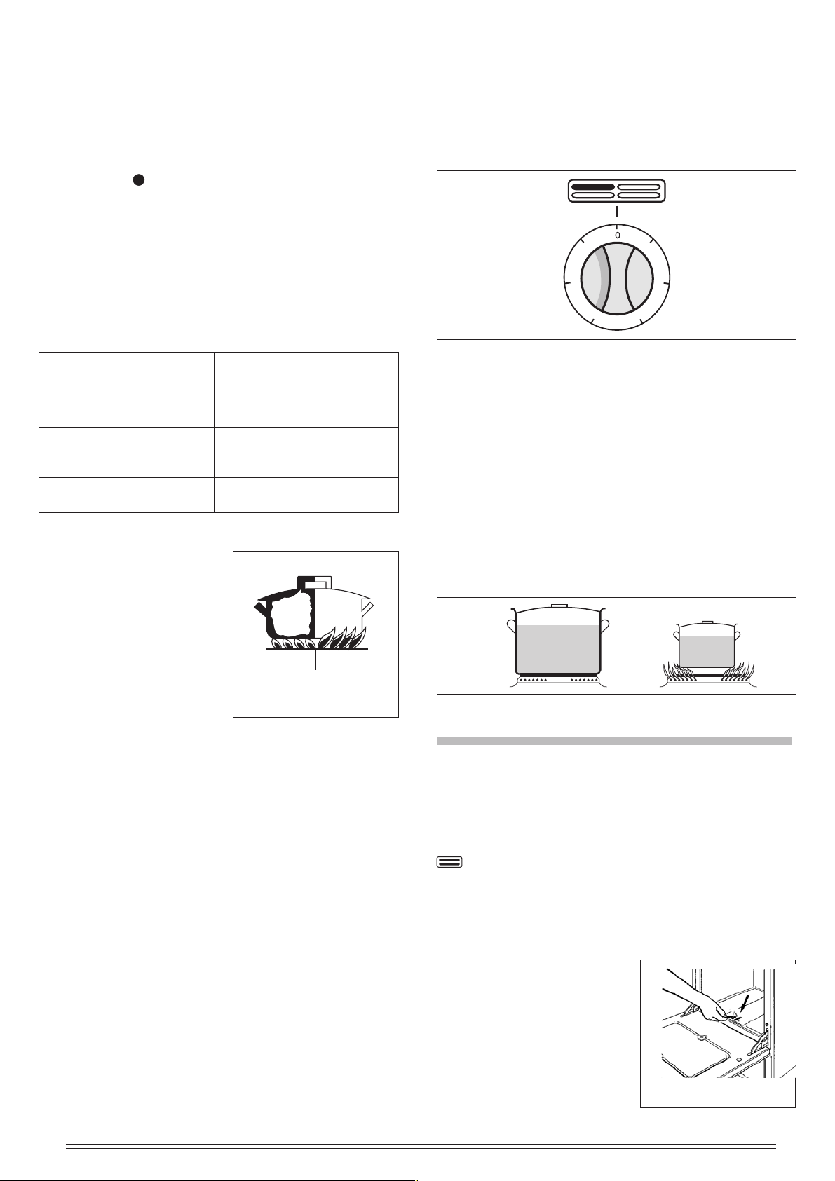
COOK-TOP
gas supply closed
maximum
gas position
Fig. 2
BURNERS USE
MANUAL LIGHTING OF THE COOK-TOP BURNERS
Put a lighted match to the burner, hold down and press the
proper knob to the left up to the max .
Turn the knob to the minimum position in order to reduce
the flame (small flame).
On the control panel next to each knob is drawn a flame
schema where it is indicated the burner position to which
the knob refers to. (fig. 2).
★
minimum
gas position
3
2 GB
LIGHTING THE BURNERS OF THE COOK-TOP
EQUIPPED WITH SAFETY THERMOCOUPLE
(automatic stop of gas supply in case of accidental flame
putting out).
In case of lack of electricity light the burner with a match,
following the instructions given in the previous paragraph.
After lighting keep hold down the knob for about 10 seconds.
The gas supply can be cut off by turning the knob clockwise
on the position (gas supply closed).
Standard plate: Ø 110 P = 800 ÷ 700 W
Ø 145 P = 1000 W Rapid P = 1500W
Ø 180 P = 1500 W Rapid P = 2000W
Every plate is controlled by a 7 positions selector (6 working
position + 0). The highest position corresponds to the max
power, while the position 1 is the minimum.
The right quantity of heat for cooking can be obtained by
selecting intermediate positions.
ADVICE FOR SAVING ENERGY
Avoid using cookware of diameter too small as to the burner
used, so that the flame does not flow out of the container.
When it starts boiling low the flame to the minimum turning
the knob to the left (fig. 3).
The use of burners depending on the cookware type shall
be as follows:
Rapid burner R1 Cookware diameter 24/26 cm
Rapid burner R
Semi-rapid burner B Cookware diameter 16/18 cm
Auxiliary burner A Cookware diameter 12/14 cm
Extra-rapid burner Ø 130 Cookware diameter 24/26 cm
Fish Kettle burner P Cookware diameter 26 oval
Triple crown burner Cookware diameter 24/26 cm
Kwali BK
REMARKS
The gas cooker during its
operating produces heat and
humidity in the room where it
is installed.
Therefore the local needs a
good airing; keep unclogged
the opening of the natural
ventilation and activate the
airing mechanical device
(extractor hood or electric fan).
In case of an intensive or long use of the appliance it is
necessary additional airing, e.g. open a window or more
effective ventilation increasing the power of the mechanical
aspiration (if any).
If the appliance is equipped with cover in tempered glass,
this can burst if overheated.
Turn off any burner before closing the cover.
The cooker with enamelled support grids are supplied with
a small reduction grid which shall be used for heating
cookware of small diameter, exclusively on the auxiliary
burner.
In case of convex pots (wook-type) it is necessary to use
on the Kwali triple-crown burner grid, the special reduction
grid, while if you use normal cookware with flat bottom it is
necessary to put on the grid a ring in order improve the
burner functioning.
USING ELECTRIC PLATES
The electric heating plates can be put on by turning the
proper knob on the control panel (fig. 4). A yellow light
indicates its functioning. The cooker is equipped with the
following plates:
2 Cookware diameter 20/22 cm
35x13 cm
RIGHT WRONG
Fig. 3
6
5
Fig. 4
1
2
3
4
PRACTICAL ADVICE
During the first plate insertion and in order to eliminate any
trace of residual humidity in the insulator, arrange for its
drying by switching on the plate for 30 minutes in position
1 without cookware.
It is possible to save energy consumption by using cookware
with flat and thick bottom (fig. 5). Never use cookware with
diameter lower than the plate.
Do not forget the plates on without cookware or with
empty vessels and make sure that the bottom of the
cookware is perfectly dry.
For a good preservation, after the use the plate shall be
lightly greased with a cloth soaked with oil so that the surface
appears clean and shining.
YES NO
Fig. 5
OVEN AND GRILL
USING THE GAS OVEN
Manual lighting of the oven
Open the oven door. Put a flame to the proper holes present
on the bottom of the oven (fig. 6), hold down and turn to the
left the proper knob on the control panel marked by the
symbol up to the maximum position (big flame).
Once it is on, keep pressed the knob for about 10 seconds
and make sure that the burner is lighted observing it by the
hole (fig. 6). The flame can be reduced turning the knob up
to the minimum position (small flame) and acting on the
temperature selected.
Before introducing food it is
recommended to heat the oven
for 15 minutes at the maximum
position. For the lighting of the
oven burner equipped with
thermostat, follow the above
mentioned instructions, keeping
in mind that the indicator of the
control knob shall be turned to
the max. position (fig. 7).
Fig. 6
GB 3
 Loading...