

Page 1

Istruzioni e consigli
per l’uso l’installazione
e la manutenzione
delle cucine
libera installazione
gas, miste ed elettriche
Instructions and suggestions
for use, installation
and maintenance
of gas and electric ranges,
combined gas
and electricity cookers
Instructions et conseils
pour l’utilisation, l’installation
et l’entretien des cuisinière
installation libre
gaz, mixtes et électriques
IT
GB
FR
Page 2
WARNING
- Read these instructions carefully before installing and
putting the appliance into use.
- The manufacturer reserves the right to change some characteristics of products whenever he may consider it necessary and useful, provided that the safety and the functionality features are warranted.
- The manufacturer declines all responsibility for any damages caused to persons, animals and things, should the
appliance not be installed or employed properly.
- This appliance complies with the following European Directives:
EN 60335-1 and further amendments
EN 60335-2-6 and further amendments
EN 30-1-1
EN 30-2-1
- This equipment is also in compliance with the essential
requirements and other provisions of the following European Directives:
- 73/23 and 93/68 EEC (Safety Standards) and 89/336 and
92/31 EEC (Electromagnetic Compatibility).
- The oven accessories which may be in contact with food
are made from materials which comply with the essential
requirements and other national provisions in force.
- The conformity of this appliance to the above mentioned
Directives is proved by the symbol stated in the rating
plate placed on the appliance rear wall.
- This appliance was designed for domestic use only and
not for professional custom.
- These instructions should be applied in the Countries
where the appliance will be sold and whose identification
symbol appears in the front page of the operator’s handbook and on the appliance, only.
IMPORTANT NOTES
- Installation and maintenance should be carried out by
skilled technicians, only (according to national provisions
in force).
- This appliance should be employed to cook foods only,
any other different application will be considered incorrect.
- The electric safety of this appliance is guaranteed provided that it is properly and efficiently grounded as required
by the General Standards on this subject.
- Do not touch the appliance if your feet and/or hands are
damp.
- Do not use the appliance barefoot.
- Do not pull the supply cable to disconnect the plug from
the outlet.
- After you finish to use the appliance you should always
check if knobs are turned to the “•” or “0” position and if
the main gas feed cock is OFF.
- Every now and then check the rubber gas feed cable state of preservation as well as its expiry date.
- The appliance should be placed in a properly ventilated
room.
- Clean the appliance to avoid the formation and the deposit of grease and food which may cause fires.
- Do not place the appliance next to inflammable materials.
- Feed the appliance with gas types and pressures stated
in the rating plate placed on the appliance rear wall.
- Do not leave the appliance exposed to atmospheric
agents (rain, sunshine and the like).
- Do not let children or incapable persons use the appliance.
- When you switch on the oven for the first time, there may
be an emission of odours and smokes due to the thermal
insulating elements and working oils. It is advisable to
leave it switched on, empty, for about an hour, with the
thermostat turned to the highest temperature value. The
room window should be left open.
- Should you not be able to make the knobs rotate easily,
we suggest you not to become alarmed about it but to call
the nearest Service Centre for maintenance.
- Attention: the glass tops may go into pieces when heated;
therefore, switch off the burners before you close the top.
- Do not absolutely sit down or rest heavy objects on the
oven door when it is open.
- Always open the door before you switch on the oven burner.
- When you use grill the oven door may be very hot, therefore you should not allow children to stand next to the appliance.
- The use of a gas range generally causes the formation of
heat and dampness in the room where the appliance is
placed. It is advisable to provide for a proper ventilation
of the room by: keeping the natural aeration openings
open or installing a mechanical ventilation system (mechanical cooker hood).
- A constant and prolonged use of the appliance may require a supplementary ventilation such as the opening of
the window or the increasing of power of the existing mechanical ventilation unit.
- When the appliance finally wears out dispose of it in compliance with local environmental protecting regulations in
force; call your nearest authorised Service Centre.
- Do not use steam jets to clean the appliance.
- Should the appliance be placed on a pedestal you must arrange the necessary precautions to prevent it from falling.
- As the appliance becomes hot when it is being used, never touch the heating elements inside the oven.
- If you live with children, we recommend you to install the
additional safety device (code 2.12AQ2002COM - available at our Assistance Service Points) on the door.
- Clean liquids overflowed on the top before you open it
and wait for the cooling of the heating surface before closing top again.
- If the surface of the glass-ceramic cooktop is cracked,
turn off the appliance to avoid possible shocks.
PLEASE NOTE: before turning on always clear away
the films from the equipment.
DESCRIPTION OF THE APPLIANCE
GB
11
INDEX
pag.
Description of the appliance.......................................11
Installation ..................................................................12
Adaptability to different gas types..............................13
Surface working gas burners -
functioning and instructions for use ...........................13
Work surface electric heating elements -
functioning and instructions for use ...........................14
Gas oven - functioning and instructions for use .......14
Gas grill - functioning and instructions for use ...........15
Electric oven functioning and instructions for use......15
Electric grill - functioning and instructions for use......16
Use of accessories.....................................................16
Cleaning .....................................................................17
Maintenance...............................................................17
Table of tecnical data .................................................18
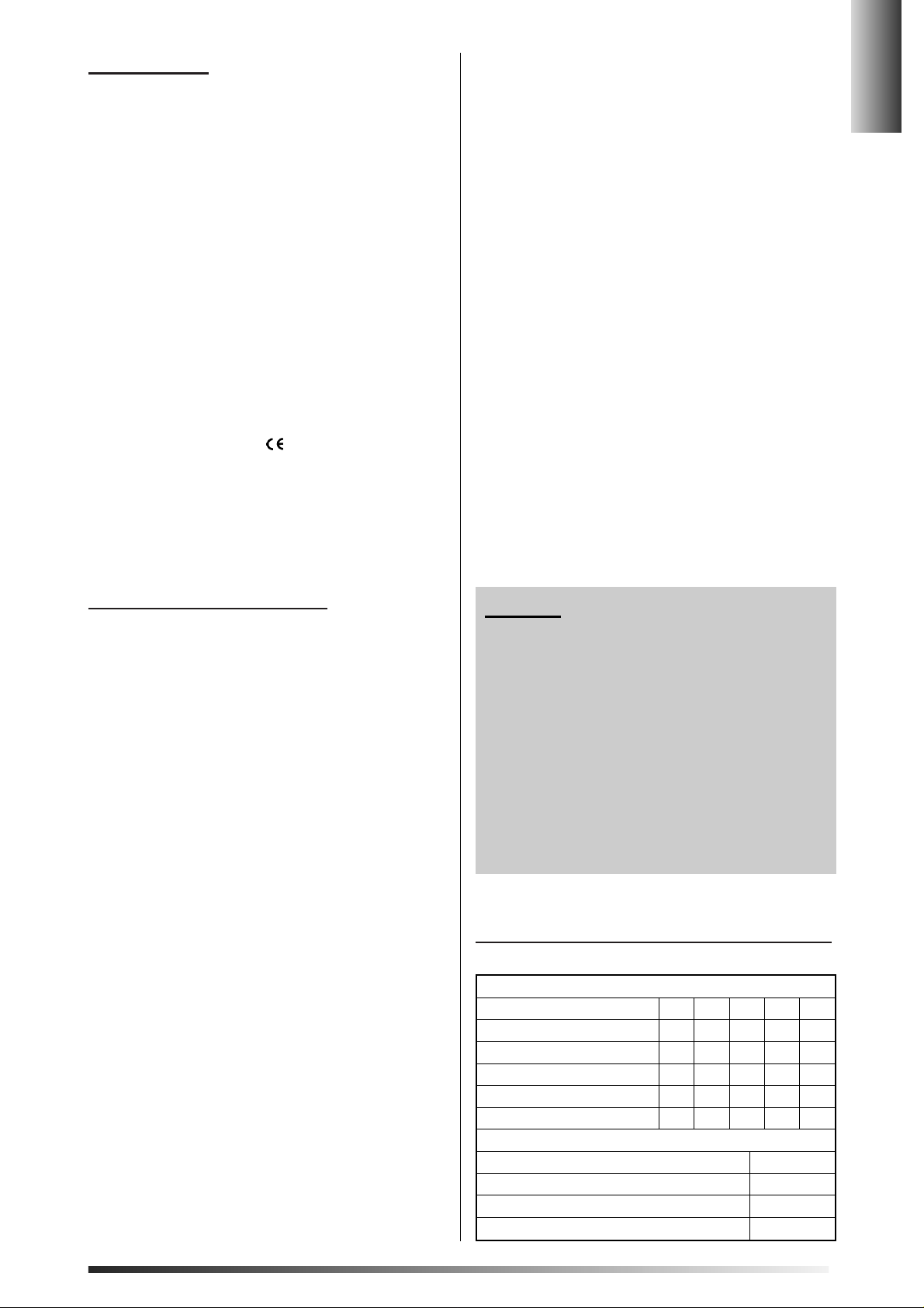
APPLIANCE EXTERNAL DIMENSIONS (mm)
Type (see data place)
C66.. C56.. C55.. C65..C50..
Height with cover plate closed
850 850 850 850 850
Height with cover plate is open
1430 1450 1400 1350 1350
Widht
600 500 550 600 500
Depth with close door
600 600 550 500 500
Depth with open door
1050 1050 960 950 950
OVEN CAPACITY expressed in litres (dm3)
Gas oven 52
Convention oven 56
Forced convention oven 54
Multifunction oven 54
Page 3
WORK SURFACE
The appliance work surface may be fitted with:
- Gas burners.
- Cast iron electric hot plates.
- Radiant elements for pyroceram cooking surface.
OVEN
The appliance may be supplied with the following types of
ovens:
- Gas oven
Heat is produced by a gas burner placed onto the bottom
of the oven.
- Electric convention oven
Heat is produced by an upper as well as a lower element
of the oven.
- Electric forced convention oven
Heat is produced by a circular element placed on the oven
back side and circulates evenly around foods by means of
a fan.
- Electric multifunctional oven
Heat can be produced either by the convention or the forced convention systems.
INSTALLATION
Installation, regulations, maintenance stated in this section should be carried out by skilled technicians only.
APPLIANCE UNPACKING
After having removed the external and internal packages relative to mobile components, check the integrity of the appliance.
In case of any doubt please do not put the appliance into
use and contact your nearest Service Centre immediately.
Please note that some elements are mounted on the appliance protected by a plastic covering that you should remove before you start using the appliance.
Never lift the cooker by means of handle.
Leave packages (cardboard boxes, plastic bags, foam
polystyrene, wrapping paper and the like) out of the
reach of children as they could be dangerous.
ROOM VENTILATION
ATTENTION:
- This appliance can be placed inside permanently
ventilated rooms, only according to the national provisions in force.
- The manufacturer declines all responsibility for any
damages should this rule not be observed.
To allow the correct functioning of the appliance you should
place it in a permanently ventilated room. The natural air
inlet should be through a passage free section of 100 cm2
at least, to be made on one of the room walls.
Mind that this opening cannot be obstructed in some
way.We suggest you to arrange it next to the floor and opposite to the area where the exhaustion of the products of
combustion takes place.
The ventilation coming from an adjacent room is also allowed, provided that the requirements of national provisions
in force are fully complied with.
ATTENTION
Should the work surface burners be free of any safety
devices, the ventilation opening size should be of 200
cm2 at least.
EXHAUSTION OF THE PRODUCTS OF COMBUSTION
Gas ranges should always exhaust the products of combustion through cooker hoods connected to smoke outlets
or directly to the outside of the building. In case there is not
a cooker hood the application of an electric ventilation unit,
either installed on a window or on a wall facing the outside, is allowed provided that the requirements of national
provisions in force are fully complied with.
APPLIANCE BACK SPACERS
For C66.. model only
To place the appliance at the right depth, install the two
screwfitted spacers into the special seats placed on the
back side of the work surface. Y ou can find the two spacers
in the accessories package inside oven.
Please note you are compelled to install the spacers.
ASSEMBLY AND LEVELLING FEET ADJUSTMENT
The appliance should stand level. It is supplied with four levelling feet to enable adjustments for uneven floor. Levelling feet should be screwed into the special seats placed
under the appliance, at its four angles.
INSTALLATION OF THE APPLIANCE
Once the installer has checked that:
- the environment is appropriate for the appliance installation,
- the supply gas corresponds to the appliance predisposition
(on the contrary arrange immediately for a new regulation)
- the gas piping is enough to feed the appliance
- the close gas cock and the socket are in a well visible and
accessible position even with the appliance installed.
- The rear spacers and levelling feet are mounted.
C66, C65 and C55 Models (fig. 1/a)
The appliance can be lean against the walls (class 2 under class
1) or at a minimum distance of 20 mm (class 1).The distance from
the suspended wall unit overhanging the working top could not be
less than 700 mm. The distance of the possible side wall, whose
height exceeds the working top, could not be less than 150 mm.
C50 and C56 Models (fig. 1/b)
The appliance could be lean against one wall only (right or left) at
a minimum distance of 20 mm (class 1). The distance of the suspended wall unit overhanging the working surface could not be
less than 700 mm.The distance of the possible side wall, that is
higher than the working top, could not be less than 150 mm.
GAS PIPELINE CONNECTION
The connection between the appliance and the gas pipeline must be in compliance with national provisions in force.To connect the appliances belonging to class 2 under
class 1 (see fig. 1/a) to the gas pipe network, you should
employ metallic flexible pipes only (according to national
provisions in force). To connect the appliances belonging
to class 1 (see fig. 1/b) to the gas pipe network, you are allowed to employ either metallic flexible pipes (according to
national provisions in force) or rubber flexible pipes (according to national provisions in force). This appliance was
set and tested with the gas type stated in the rating plate
placed at the rear of the appliance. Check the correspondence between that type of gas and the supplied gas before you connect the appliance. Install a gas cock downstream the appliance in a well visible and accessible position and check if the gas pipeline flow is enough to feed the
appliance and if the supplied gas pressure corresponds to
that of the gas type stated in the rating plate. Gas and electricity data are stated in the rating plate placed at the rear
of the appliance.The connection to the gas pipe network
can be effected as follows:
- By means of a stainless steel flexible pipe with continuos
wall in compliance with national provisions in force with a
maximum extension of 2 metres; seals must be in compliance with national provisions in force
- By means of a rubber flexible pipe not longer than 1,5
metre in compliance with national provisions in force; it
must neither be under tensile and/or torsional stress nor
have throttling; it must be properly visible all along its path
and be set not to be in contact with cutting objects and/or
sharp corners; at no points its temperature must be higher than 50°C.
GB
12
Page 4
GB
13
- For gas in cylinder belonging to the III group (LPG) you
must employ a 8 mm internal diameter pipe and hose-end
while for gas belonging to the II group (methan) you must
employ a 13 mm internal diameter pipe and hose-end. At
the ends of the pipe the rubber seal should be assured by
safety hose clamps in compliance with national provisions in force.
- Should gas in cylinder belonging to the III group be used,
employ pressure regulators in compliance with national
provisions in force, only. After the connection make sure
that there is no lack of gas by means of special instruments or soapy water.
Never use free flames.
ATTENTION:
- Never let the rubber flexible pipe go from one side to
the other of the appliance.
- When you change the hose-end you should always
substitute seals, too.
ELECTRIC CONNECTION
The connection to the mains supply has to be made according to current standards and regulations.
Before you effect the connection you should check if:
- The voltage stated in the rating plate (at the rear of the
appliance) corresponds to the voltage of your electricity
supply.
- Both the outlet and the electric system are grounded.
- Do not use reducing sockets, plug adaptors or shunts as
they may cause false contacts with consequent dangerous overheating.
N.B. Feed cable must never be in contact with appliance hot elements.
Connection to supply mains through outlets
If not present, apply a standardized plug to the supply cable suitable for the voltage stated in the rating plate.
Connect the cable wires according to following instructions:
L = (Phase) Red or brown wire
N = (Neutral) Blue wire
=( Ground) Yellow-green wire
See pict. 2 at the end of this handbook
Once installation is completed both plug and outlet
must be easily reachable.
Direct connection to supply mains
Install an omnipolar switch between the appliance and the
supply mains adapted to the appliance voltage with 3 mm
minimum opening between contacts.
Note: the ground wire must not be interrupted by the switch.
Alternatively, the connection could also be protected with a
high sensitivity residual current operated circuit-breaker.
ADAPTABILITY TO DIFFERENT
GAS TYPES
Attention
Nozzles, pipe connectors and the relative setting tags
for the regulation to different supply gas types are
available at our authorized Service Centres.
After having adjusted the appliance to gas types, remove
the original setting tag placed at the rear of the appliance
and replace it with a new label, supplied with nozzles, corresponding to the new gas type.
After the new adjustment is completed, you should seal
every by-pass again by means of sealing wax or other fireretardant materials.
WORK SURFACE GAS BURNERS REGULATION
Always disconnect appliance from the electricity
supply and close the gas cock downstream the appliance before starting any operation.
Injector replacement
To effect this operation you should proceed as follows:
- Remove the work surface grate, the flame-baffles and the
burners heads from their original position.
- Take from the injectors tag those relative to the type of
burner and gas for which the adjustment is required.
- Remove injectors by means of a 7 mm socket spanner
and set the new injectors by means of the same socket
spanner.
- Replace the burners heads, the flame-baffles and the
grates into their original positions.
Air regulation
The work surface gas burners do not need any air regulation.
Low point control
Remove knob and control the gas cock by-pass screw
through the facia-panel by means of a small screwdriver ;
it may be placed on the right of the small rod or inside it.
By unscrewing counterclockwise you will increase the gas
flow while by unscrewing clockwise you will decrease it.
For the setting of gas flow belonging to III group (LPG), you
must screw the by-pass to stop. When you have completed these operations, switch on the burner, turn the knob
from the highest to the lowest position quickly for three times: burner has not to switch off. Repeat this operation for
every burner present on the work surface. For gas cocks
fitted with flame safety devices, once the flame low point is
regulated it is advisable to leave burner on for a few minutes to make sure that the safety device does not lock.
GAS OVEN BURNER REGULATION
Injector replacement
To effect this operation you should proceed as follows:
- Unscrew the burner front screw and remove it from its
seat, be careful not to damage the ignition spark plug (if
any) and/or the thermocouple.
- Remove injector by means of a 7 mm socket spanner.
- Replace burner into its original seat.
- Lock burner with the front screw by pushing it towards the
back side of the appliance.
- The oven burner does not need any air regulation.
Low point control
Remove the corresponding knob and control the oven valve/thermostat by-pass screw through the facia-panel by
means of a small screwdriver: it may be placed on the right
of the small rod or inside it. By unscrewing counterclockwise
you will increase the gas flow while by unscrewing clockwise
you will decrease it. For the setting of gas flow belonging to
the III group (LPG), you must screw the by-pass to stop.
When you have completed these operations, switch on the
burner, turn the knob from the highest to the lowest position quickly for three times: burner has not to switch off.
GAS GRILL BURNER REGULATION
Injector replacement
To effect this operation you should proceed as follows
- Unscrew the burner front screw and remove it from its
seat, be careful not to damage the ignition spark plug (if
any) and/or the thermocouple.
- Remove injector by means of a 7 mm socket spanner.
- Replace burner into its original seat
- Lock burner with the front screw by pushing it towards the
back side of the appliance.
- Grill burner needs neither air regulation nor low point control.
SURF
ACE WORKING
GAS BURNERS - FUNCTIONING
AND INSTRUCTIONS FOR USE
Manual ignition
Do not put any pot on the burner. Light a match and bring
it near to the burner; then, push and rotate the knob coun-
Page 5

terclockwise as far as the pointer coincides with the high
flame symbol . If you wish to reduce flame you should
go on rotating the knob counterclockwise as far as it gets
the small flame symbol .
In the facia-panel you can find a scheme, in respect of
each and every knob, showing the corresponding burner
position.
Electric ignition (if any)
Do not put any pot on the burner. Push the desired burner knob
and rotate it counterclockwise as far as it gets the high flame
symbol , at the same time push the ignition button .
The sparks produced by the ignition spark plug will cause
the burner ignition.
Integrated ignition (if any)
Do not put any pot on the burner, rotate the selected burner
knob counterclockwise until the high flame and push the
knob, in this way automatically switches on the burner.
Flame safety device (if any)
This device is able to stop gas output immediately in case of
flame out.T o restart burner repeat the instructions stated above according to your appliance model then, keep knob pressed for 10 seconds to start the safety device. Should burner
switch off you should repeat the sequence stated above.
Use flat bottom pots only.
WORK SURFACE
ELECTRIC HEATING
ELEMENTS - FUNCTIONING
AND INSTRUCTIONS FOR USE
General information and precautionary measures
To obtain the highest performance with the lowest electrical input we suggest you to proceed as follows:
- Turn on the power only after having put the pot on the hot
plates or cooking unit.
- Do not use pots with a diameter lower than that of the hot
plates or cooking unit.
- Use flat bottom and high thickness pots. Use lid-fitted
pots.
- Dry the pot bottom before resting it on the hot plates or
cooking unit.
- If cooking times are longer than 40 minutes turn off the
power of the hot plates or cooking unit 5-10 minutes before the end of the cooking time to exploit the residual
heat.
- Do not use the pyroceram cooking surface as a bearing
surface and also be careful not to hit it with hard and
sharp objects.
- Do not stare at the halogen heating elements of the pyroceram cooking surface.
- Avoid cooking empty pots.
- Do not creep the pyroceram cooking surface with pots or
other objects.
- Avoid pouring liquids.
- Remove poured out liquids from the cooking unit by
means of the scraper purposely studied for pyroceram
cooking surfaces.
- Should the range be fitted with crystal top this might explode if heated, therefore mind to turn off hot plates or
heating elements before closing the top.
- As soon as you note a crack of the pyroceram cooking
surface disconnect the appliance from the electric supply
immediately.
Work surface includes pilot lights that switch on when the
cooking units temperature is higher than 60°C and switch
off when temperature drops below that value.
Cast iron plates
Cookers may be fitted with the following two different electric hot plates:
- normal speed
- high-speed (red mark)
Both plates are controlled by selector switches. The main advantage of the high-speed plate is a quicker cooking time. By rotating
the knob clockwise you will read the following symbols:
0 = Hot plate or heating elements OFF
from 1 to 6 = MIN and MAX power positions
On first ignition or if hot plate has not been used for a long
time, it is necessary to turn the selector switch to the 1 position and leave it there for 30 minutes in order to dry the
humidity absorbed by the insulating element.
Normal heating element for pyroceram cooking surface
Normal heating elements are controlled by selector switches.
Cooking units are identified with circles on the work surface.
Hi-light and halogen heating element for pyroceram
cooking surface
Heating elements are controlled by energy regulators.
Double-circuit Hi-light heating element for pyroceram
cooking surface
The double-circuit heating element is controlled by an energy regulator with a regulation schematic field which goes from 0 to 5.
By rotating the knob clockwise you will read the following
symbols: l
To switch on a single heating element rotate the knob
clockwise from zero “0” to the desired position.To switch on
the second heating element rotate the knob clockwise as
far as it gets the symbol, then release the knob and set the
desired position.
GAS OVEN - FUNCTIONING
AND INSTRUCTIONS FOR USE
General information and precautionary measures
On first ignition we suggest you to heat oven at the highest
temperature for about an hour keeping the door closed.
This has to be done to remove the odours caused by the
glass wool insulation and working oils. The room windows
should always be open when starting gas oven.
While using the oven the top should always be open to make the exhaustion of combustion waste easier.
- Always grasp the central part of the handle to open the
oven door.
- At the end of cooking, on the opening of the oven door you
should always be careful to the boiling fumes emission.
- Always use insulating gloves to put in and to take out pots
from the oven.
- The oven temperature range goes from a minimum of
160 °C to a maximum of 260-270°C
Manual ignition
Open the oven door, light a match and bring it near the
oven burner ignition tube through the slot (between the two
small holes) placed onto the oven hearth front side; push
and rotate the oven knob counterclockwise up to the maximum position. Once the oven is switched on, keep the
knob pressed for about 5-10 seconds and make sure that
burner stays on by looking at the flames through the two
small holes in the oven hearth front side (see pict. 3 at the
end of this handbook).
Electric ignition (if any)
Always open the oven door, rotate the knob counterclockwise up to the highest position, press the button marked
with the following symbol on the facia-panel; as far
as appliances fitted with integrated ignition (marked with a
star icon) are concerned, ignition will be effected automatically by keeping knob pressed.
Flame safety device
This device (always present) is able to stop gas output automatically in case of flame out. Repeat the instructions
stated in the previous paragraphs to ignite oven again.
GB
14
Burner Pot diameter
TC (triple burner) from 220 to 260 mm
R (large) from 220 to 260 mm
SR (medium) from 160 to 240 mm
A (small) from 120 to 140 mm
Page 6

GB
15
The flame safety device should not work for more than 15
seconds. If, after that time, burner has not switched on yet,
you should interrupt the device, open the compartment
door and/or wait for 1 minute at least before trying to ignite burner again.
N.B: To warm cold or already cooked food we suggest you
to use the oven at its lowest temperature.
GAS GRILL - FUNCTIONING
AND INSTRUCTIONS FOR USE
General information and precautionary measures
While using grill the top should always be open to make the
exhaustion of combustion waste easier.
- Always grasp the central part of the handle to open the
oven door.
- During or at the end of cooking, on the opening of the
oven door you should always be careful to the boiling fumes emission.
- Always use insulating gloves to put in and to take out pots
from the oven.
- Use pots resistant to the temperatures stated in the thermostat knob.
- After you finished to use the appliance make sure that all
controls are turned to the OFF/CLOSED position.
The gas grill burner always work at its highest power.
To cook with gas grill, place grill onto the highest guide and
the dripping pan onto the underneath guide.
Manual ignition
Open the door, install the knobs heat buffer (supplied
with the appliance), light a match and bring it near the
burner, then push and rotate the knob clockwise up to the
grill position identified by the symbol: .
Once the oven is switched on, keep the knob pressed for
about 5-10 seconds and make sure that burner stays on.
Now bring the oven door near the heat buffer. The knobs
heat buffer can be manually operated by means of the two
bushes placed under the facia-panel.
The manufacturer declines all responsibility for all damages should the gas grill be employed with the door
closed or half-closed or without the knobs heat buffer.
Electric ignition (if any)
Always keep the oven door open, rotate the oven knob clockwise up to the grill position identified with symbol .
Push the button with the symbol placed in the faciapanel; as far as appliances fitted with integrated ignition
(marked with a star symbol) are concerned, ignition will be
effected automatically by keeping knob pressed.
Flame safety devices
This safety device (always present) is able to stop gas output automatically in case of flame out. Repeat the instructions stated in the previous paragraphs to ignite oven again.
ELECTRIC OVEN – FUNCTIONING
AND INSTRUCTIONS FOR USE
General information and precautionary measures
- Always grasp the central part of the handle to open the
oven door.
- During or at the end of cooking, on the opening of the
oven door you should always be careful to the boiling fumes emission.
- Always use insulating gloves to put in and to take out pots
from the oven.
- Use pots resistant to the temperatures stated in the thermostat knob.
- After you finished to use the appliance make sure that all
controls are turned to the OFF/CLOSED position.
In the electric oven facia-panel you will find two knobs as follows:
- Thermostat knob: it allows to regulate cooking temperature.
- Oven functions selection knob: it allows to select cooking
functions.
Oven lamp
The symbols you will find on the oven selection knob depend on the model you bought; in any case, for all models
the first symbol corresponds to the lamp switching-on function identified with the above icon. The lamp stays on even
when you select other functions.
The spit-roaster
General information and precautions for use After cooking
the spit and its seat are very hot: always wear thermal protective gloves. Accessible parts of the cooker may be hot during the use of the spit. Keep the children away. For ovens
equipped with a gas grill the use of the spit shall be made
with half-open door, with a protective heat-shield and under
a careful surveillance. Spit, marked with symbol is available with few models only. Such icon may also be next to
other functions symbols as follows: this means
that by selecting the simple grill function, split will start too.
N.B. For C50E and C56E models the maximum temperature of use as to electric grill with spit is 200° C.
Cooking advice
How to bake sweets
- Before you put sweets to bake in the oven you should always preheat oven for 15 minutes at least.
- Do not use the glazed oven tray supplied with the appliance to bake sweets.
How to grill food
- Apply dripping and spices on foods before you start to
grill them.
- You should always use the dripping pan to collect sauce
from meats and place it underneath the grill or lay it down
on the oven bottom.
- You should always pour some water into the oven tray to
prevent greases from producing fumes and nasty smell.
- Add water during cooking to avoid its complete evaporation.
- Turn food at half cooking point.
- When you cook fat poultry you should always make a hole into the skin to allow grease to come out.
Cooking functions
Simple Grill
By selecting this function you activate the upper central
grill resistance that radiates heat directly on foods. Set the
desired temperature by means of the thermostat.Keep the
oven door closed.
Double grill
By selecting this function you activate the two upper resistances that radiate heat directly on foods. Set the desired temperature by means of the thermostat. Keep the oven door closed.
Convention oven
Traditional convention baking. By selecting this function
you activate the two upper and lower resistances to bake
food evenly. To select this function you should turn the
thermostat knob to the desired temperature. It is suitable
for baking every type of food (meat, fish, bread and pizza).
Forced convention oven
By selecting this function you activate the back circular resistance; a system of forced air using a powered fan makes
the heat circulate evenly around the food allowing to cook it
quickly even if placed on more shelves. To select this function you should turn the thermostat knob to the desired temperature. It is suitable for baking sweets, meat, fish, bread
and pizza in quicker times and/or on one or more shelves.
Forced double grill
By selecting this function you activate the two upper resistances; a system of forced air using a powered fan makes
the heat circulate evenly around the food. To select this
function you should turn the thermostat knob to 200 °C
temperature. This function is suitable for obtaining even
and crackling golden-brown foods.
Page 7

GB
16
Traditional cooking with powered fan
By selecting this function you start the two upper and lower
resistances and heat circulates evenly around the food by
means of a powered fan. To select this function you should
turn the thermostat knob to the desired temperature.
This function is suitable for cooking on a single shelf.
Light oven
By selecting this function you start the lower resistance.
To select it you should turn the thermostat knob to the desired temperature. You can choose this type of cooking
when you need to cook better the bottom of your food.
ELECTRIC GRILL - FUNCTIONING
AND INSTRUCTIONS FOR USE
- T o open the oven door always grasp the handle in the centre.
- During or at the cooking ending pay attention to possible
emission of superheated steams when you open the door.
- Always use thermal gloves to put pans in or out the oven.
- After appliance use make sure that all controls are in
off/closed position.
For appliances equipped with electric oven the electric grill
function may be used with closed door.For appliances
equipped with gas oven the electric grill shall be used with
half-open door and handgrip heat-shield mounted; as the
grill is an element used for final touch-ups it is advisable to
use it for max 20 minutes.
USE OF ACCESSORIES
Timer
Your range can be fitted with this accessory that you can
wind by rotating the corresponding knob clockwise by one
complete turn and set the pointer to the desired cooking time (expressed in minutes) by rotating the knob counterclockwise. The set time running out will be signaled by a bell.
Electric timer
Your range can be fitted with this accessory acting both as
a clock and as a timer as well. To set hour push and rotate the small knob counterclockwise. To set minutes rotate
the small knob counter clockwise without pushing it.
Timer with cooking end function
Your range can be fitted with this double functional accessory: it can show the cooking time that has already passed
and automatically turn off the oven. You can set the desired cooking time by rotating the timer knob clockwise;
when this time has passed the acoustic warning signal
switches on and contemporaneously the automatic cooking end device starts.
As far as the oven connection modes are concerned please refer to the handbook specific paragraphs.
If you desire to use the oven without the timer function you
should turn the knob to the symbol (manuel).
N.B. When the knob pointer is set to “0” position, oven
cannot work.
Electric clock supplied with cooking end device
Range can be fitted with this double functional accessory:
it consists of a clock able to turn off oven automatically
when the set cooking time has run out.
To set hour push and rotate the small knob counterclockwise.
To set minutes rotate the small knob counterclockwise without pushing it.
When the set time has run out the acoustic warning signal
starts to inform that oven is off.
Turn the knob to the symbol to stop it.
If you desire to use oven without setting a cooking time you
should rotate the knob pointer counterclockwise to the
symbol (manuel).
N.B. When the knob pointer is set to “0” position and
to symbol , oven cannot work.
Electronic programmer
Your range can be fitted with this accessory whose main
functions are:
- Clock (to be set with push buttons 2 and 3).
- Timer (to be set with push button 1).
- Cooking time (to be set with push button 2).
- Cooking end time (to be set with push button 3).
- Manual working (to be set with push button 4).
- Regulation of times “backward” (to be set with push button 5).
- Regulation of times “forward” (to be set with push button 6).
The digital display “D” (see pict. 4 at the end of this handbook) shows the hour, the cooking time and the cooking
end time.
Time setting
After the electric connection or a lack of current, on the
display the “AUTO” e “0.00” signals will flash at the same
time. Push and release contemporaneously push buttons 2
and 3 and start setting the current hour by pushing either
button 4 or 5 within 4 seconds. Once the setting is over no
symbol will be on.
Timer
Push button 1 and select your cooking time by means of either button 4 or 5.
The symbol will lit up.
When the set time has run out, the acoustic warning signal
starts and the symbol will flash. After the bell disconnection that symbol will disappear.
Half-automatic working mode (cooking time)
By pushing button 2 and setting the cooking time by means
of button 5, both the “AUTO” and the symbol will lit up.
When the set time has run out, the symbol will switch
off while the “AUTO” symbol flashes and the acoustic warning signal starts.
Half-automatic working mode (end of cooking time)
By pushing button 3 and setting the end of cooking time by
means of button 5, both the “AUTO” and the symbols
will lit up.
When the set time has run out, the symbol will switch
off while the “AUTO” symbol flashes and the acoustic warning signal starts.
Automatic working mode (postponed cooking start time)
First you should set your cooking time (both the “AUTO” and
the symbols will lit up) and then the cooking end time,
the symbol will switch off as previously stated.
The symbol will lit up again when the oven starts baking.
When cooking time has run out, the symbol will switch
off while the ”AUTO” symbols flashes and the acoustic warning signal starts.
Manual working
Manual working is possible only after having cleared the
automatic program by pushing button 3. The “AUTO”
symbol disappears and no other symbols lit up.
Acoustic warning signal
The acoustic warning signal starts at the end of a program
and lasts about two minutes. To interrupt it you should
push one of the function buttons.
Program start and check
Program starts after about 4 seconds from the setting. It is
possible to check the set program at any time by pushing
the corresponding button.
Correction and cancellation of program
It is possible to correct the set program at any time by first
pushing the relative programming button and then buttons
4 or 5. It is possible to cancel a program by changing the
set time to “0.00”. By cancelling the working time you will
automatically cancel the working end time and vice versa.
Oven automatically switches off while the “AUTO” symbol
flashes. Push button 3 to set the programmer to manual
working mode. Time cannot be corrected when the automatic working program is on.
Page 8

GB
17
Oven lamp
The oven lamp is controlled by a switch placed in the faciapanel of the models supplied.
Spit
Spit is controlled by a switch placed in the facia-panel of
the models supplied.
Warning pilot lights
Red pilot light. When it is switched on it indicates that a
heating element is on.
Orange pilot light. When it is switched on it indicates that
the oven thermostat is on.
CLEANING
General information and precautionary measures
Always disconnect appliance from the electricity
supply before you start cleaning.
Close the gas feed cock.
Never throw water directly on still warm components.
CRYSTAL SURFACES
To clean crystal surfaces (cooker top and oven door) use a
sponge with a small quantity of liquid detergent, then with
a sponge soaked with warm water and at the end with a
dry cloth.
GLAZED, PAINTED AND STAINLESS
STEEL SURFACES
Clean the range glazed and painted parts in the same way
as per crystal surfaces (see above). Clean when elements
are cold, only.
Use neither metallic and/or plastic, sponges nor abrasive powders nor corrosive sprays.
Neither sprinkle nor wash the resistances and the thermostat bulb with acid-based products.
The manufacturer declines all responsibility for any
damages caused to persons, animals and things
should the appliance not be cleaned properly.
MAINTENANCE
General information and precautionary measures
Always disconnect appliance from electricity supply
before you start maintenance operations and make sure that the gas feed cock is closed.
Rubber gas feed pipe replacement
We suggest you to check the rubber gas feed pipe state of
preservation every now and then and to replace it every five years.
Should it present any fissure, cut, abrasion or burning replace it immediately with a new pipe in compliance with
provisions in force.
Feed cable replacement
We suggest you to check the feed cable state of preservation every now and then.
Should it present any fissure, cut, abrasion or burning replace it immediately with a new cable corresponding to the
“Feed cables types and sections” table.
To replace cable you should proceed as follows:
- Disconnect appliance from the electricity supply
- Open the terminal strip cover.
- Remove the three screws fixing the cable terminals and
the screw fixing the cable press.
- Connect the new feed cable to the cooker terminal strip
keeping the ground wire length longer than that of the
phase and neutral wires.
- Close the terminal strip cover.
N.B. Mind that at no point the feed cable should reach
a temperature higher than 75K.
Electric ovens power
Convention oven 2,00 kW
Forced convention oven 1,80 kW
Grill 2,10 kW
Voltage 230 V~
FEED CABLES TYPES TYPE OF INPUT INPUT INPUT INPUT
AND SECTION CABLE 230 V~ 230 V~ 3 400 V~ 2N 400 V~ 3N
TOTAL GAS H05 RR-F 3x0,75 mm
2
///
MIXED UP TO 1000 W H05 RR-F 3x0,75 mm
2
///
MIXED UP TO 200 W H05 RR-F 3x1 mm
2
///
MIXED UP TO 3400 W H05 RR-F 3x1,5 mm
2
4x1,5 mm
2
4x1,5 mm
2
5x1,5 mm
2
MIXED UP TO 3900 W H05 RR-F 3x2,5 mm
2
4x2,5 mm
2
4x2,5 mm
2
5x1,5 mm
2
* ELETTRIC UP TO 8400 W H05 RR-F 3x2,5 mm
2
4x2,5 mm
2
4x2,5 mm
2
5x1,5 mm
2
* ELETTRIC UP TO 9400 W H05 RR-F 3x4 mm
2
4x2,5 mm
2
4x2,5 mm
2
5x2,5mm
2
* The contemporaneity factor was taken into account
Page 9

GB
18
BURNERS TYPE C66..
Max power 1,0 kW - 73 g/h (G30) - 71 g/h (G31)
Min power 0,45 kW
Gas G20 G30/31
A
Pressure (mbar) 20 28-30/37
Injector (1/100 mm) 72 x 50
by-pass (1/100 mm) Regulated 32
Max power 1,75 kW - 127 g/h (G30) - 125 g/h (G31)
Min power 0,5 kW
Gas G20 G30/31
SR
Pressure (mbar) 20 28-30/37
Injector (1/100 mm) 97 Z 65
by-pass (1/100 mm) Regulated 34
Max power 3,0 kW - 218 g/h (G30) - 214 g/h (G31)
Min power 0,8 kW
Gas G20 G30/31
R
Pressure (mbar) 20 28-30/37
Injector (1/100 mm) 115 Y 85
by-pass (1/100 mm) Regulated 42
Max power 3,3 kW - 240 g/h (G30) - 236 g/h (G31)
Min power 1,35 kW
Gas G20 G30/31
TC
Pressure (mbar) 20 28-30/37
Injector (1/100 mm) 125 T 91
by-pass (1/100 mm) Regulated 57
Max power 2,0 kW - 145 g/h (G30) - 143 g/h (G31)
Min power -
Gas G20 G30/31
Pressure (mbar) 20 28-30/37
Injector (1/100 mm) 102 Z 70
by-pass (1/100 mm) - Max power 3,1 kW - 225 g/h (G30) - 221 g/h (G31)
Min power 0,95 kW
Gas G20 G30/31
Pressure (mbar) 20 28-30/37
Injector (1/100 mm) 115 Y 85
by-pass (1/100 mm) Regulated 48
OVEN GRILL
BUNERS TYPE C50.. C55.. C65.. C56..
Max power 1,0 kW - 73 g/h (G30) - 71 g/h (G31)
Min power 0,45 kW
Gas G20 G30/31
A
Pressure (mbar) 20 28-30/37
Injector (1/100 mm) 77 50
by-pass (1/100 mm) Regulated 32
Max power 1,75 kW - 127 g/h (G30) - 125 g/h (G31)
Min power 0,5 kW
Gas G20 G30/31
SR
Pressure (mbar) 20 28-30/37
Injector (1/100 mm) 101 665
by-pass (1/100 mm) Regulated 34
Max power 3,0 kW - 218 g/h (G30) - 214 g/h (G31)
Min power 0,8 kW
Gas G20 G30/31
R
Pressure (mbar) 20 28-30/37
Injector (1/100 mm) 129 87
by-pass (1/100 mm) Regulated 42
Max power 2,0 kW - 145 g/h (G30) - 143 g/h (G31)
Min power -
Gas G20 G30/31
Pressure (mbar) 20 28-30/37
Injector (1/100 mm) 102 Z 70
by-pass (1/100 mm) - Max power 3,1 kW - 225 g/h (G30) - 221 g/h (G31)
Min power 0,95 kW
Gas G20 G30/31
Pressure (mbar) 20 28-30/37
Injector (1/100 mm) 115 Y 85
by-pass (1/100 mm) Regulated 48
OVEN GRILL
Verify the burners type and identify the respective injectors before any change of gas regulation.
Check the symbol under the burner caps:
Burners SABAF Burners DEFENDI
These values refer to the cooking effected on a single shelf. If you use more than
one shelf (2° and 3° guides) you shall increase the cooking times of 5-10 minutes.
BURNERS TYPE C50..
Max power 2,0 kW - 145 g/h (G30) - 143 g/h (G31)
Min power -
Gas G20 G30/31
Pressure (mbar) 20 28-30/37
Injector (1/100 mm) 102 Z 70
by-pass (1/100 mm) - Max power 2,3 kW - 167 g/h (G30) - 164 g/h (G31)
Min power 0,95 kW
Gas G20 G30/31
Pressure (mbar) 20 28-30/37
Injector (1/100 mm) 100 Y 72
by-pass (1/100 mm) Regulated 48
TAP GRILL
GAS OVEN COOKING TIME TABLE
Oven guide Cooking
Foods
Weight position Temperature times
(kg) from (°C) expressed
the bottom in minutes
Meats
Roast veal 1 2 180 100-110
Roast beef 1 2-3 180 50-60
Roast pork 1 3 190 90-100
Roast lamb 1 2-3 190 110-120
Filet of beef 1 2-3 170 90
Sausage 1 2-3 170 60
Game
Roast hare 1 2-3 180 90
Roast pheasant 1 2-3 200 90
Roast partridge 1 2-3 190 50-60
Poultry
Roast chicken 1 2-3 180 90
Roast turkey 1 2 220 100-120
Roast duck 1 2 220 90-100
Rabbit 1 2-3 180 100
Cut of turkey 1 2-3 180 80
Guinea fowl 1 2-3 180 80
Duck 1 2-3 180 100
Roast fish 12180 50-60
Pasta pie
Lasagne 1 2-3 200 50-60
Cannelloni 1 2-3 200 50-60
Pizza 13200 30
Bread 12210 30-40
Sweet
Biscuits 1 3 180 30
Sponge cake 1 2-3 180 50
Ring cake 1 3 180 40-50
Cakes
Apple cake 1 3 180 50
Tart 1 3 180 50
Meringue 1 3 150 40-50
Profiteroles 1 3 180 30-40
Soufflè 1 3 180 40-50
Baked fruit
Apple 1 3 180 60
Pears 1 3 180 60
These values (temperatures and cooking times) may vary according to the food
quality and thickness.
GAS GRILL COOKING TIME TABLE
Oven guide Cooking
Foods
Weight position Temperature times in
(kg) from the (°C) minutes
bottom 1° and 2° site
Meats
Sirloin steak 1 3 MAX 8-8
Steak - 3 MAX 5-5
Cut chicken 1 3 MAX 18-18
Fish
Trout - 2 MAX 9-9
Sole - 2 MAX 7-7
Bread
Toast - 3 MAX 3-3
Chicken 13MAX 45-50
Page 10

GB
19
Indicative table for electric grill cooking
Static and fan electric oven cooking chart
Food
Meats
Entrecote 0,50 3 MAX 8 8
Steack 0,15 3 MAX 5 5
Chicken (cutted) 1 3 MAX 18 18
Fish
Trout 0,42 2 MAX 9 9
Sole 0,20 2 MAX 7 7
Bread
Toast - 3 MAX 3 3
Chicken 1,3 3 MAX 45-50
The values shown (temperatures and cooking times) are approximate and may vary depending on the type of meat and its thickness.
Weight
Position of oven shelf on Cooking times
kg
the runner frame,
starting from the bottom
Temperature
°C
st
side 2stside
1
in minutes
Static Fan
Weight °C Minutes °C Minutes
Meats
Roast veal 1 200 120 180 100
Roast beef 1 210 45 190 35
Roast pork 1 200 120 180 90
Roast lamb 1 200 120 190 100
Filet beef 1 210 45 190 35
Sausage 1 200 40 190 30
Game
Roast hare 1 200 100 190 90
Roast pheasant 1 200 100 190 90
Roast cartridge 200 100 190 90
Poultry
Roast chicken 1 200 70 190 60
Roast turkey 1 200 70 190 60
Roast duck 1 210 70 200 60
Rabbit 1 200 70 190 60
Tu r key rump 1 200 70 190 60
Guinea-fowl 1 210 70 200 60
Duck 1 210 70 200 60
Fish
Roast fish 1 190 60 180 50
Oven pasta
Lasagne 1 180 40 170 30
Cannelloni 1 180 40 170 30
Pizza 1 200 30 180 25
Bread 1 210 40 200 35
Pastres
Biscuits 1 180 30 170 25
Sponge cake 1 180 40 170 30
Doughnut 1 180 40 170 30
Cakes
Apple-pie 1 180 40 170 30
Jam tart 1 180 40 170 30
Meringue 1 120 30 120 25
Cream puff 1 180 30 170 25
Soufflè 1 180 30 170 25
Baked fruit
Apples 1 180 30 170 25
Pears 1 180 30 170 25
The shelves position is: 2-3 guides from the bottom. The esteemed weight is 1 kg.
Page 11

Page 12

ED. 4/11/2003 2.12VAR025004
spazio
per targa dati
GB
FR
IT
 Loading...