

Page 1
7509 D
Einbau-Flachschirm-Dunstabzugshaube
Built-In- Flat-Screen Fume Extractor Hood
Montage- und Gebrauchsanweisung
Installation and Operating Instructions
Page 2
Summary
Safety warnings Page
For the electrical installer 30
For the kitchen furniture installer 30/31
Before installation
General information 32
Appliance description 32
Technical data: 33
- Dimensions 33
- Electrical connection data 33
- Air outlet 34
- Accessories/installation material 35
Installation
Preparation of the cabinet 36
Installation of the cooker hood 37-40
Recycling installation 41/42
Evacuation installation 43/44
Electrical connection 45/46
Safety warnings
for the user 47
Appliance description/controls
- Controls 48/49
Maintenance
- Metal filters (cleaning) 50
- Charcoal filters (only in recycling version) 51
- Fluorescent strip light/Starter 52-54
- General cleaning instructions 54
Special accessories 55
After Sales Service 55
28
SYSTEM
OKO
MADE IN GERMANY
Printed on recycled paper.
AEG - putting words into action.
29
Page 3
Safety warnings
For the
electrical
installer
For the
kitchen
furniture
installer
30 31
The installation of a socket immediately above the cooker hood
or the cabinet has two advantages:
1. The socket is out of sight
2. If necessary, the cooker hood can be disconnected by
removing the plug.
Should it be necessary to connect the hood permanently, this
should be carried out only by a qualified electrician or a
competent person. Connect the hood to the mains supply via
a double pole switch which has 3mm minimum clearance
between the contacts.
Suitable double pole switch breakers are e.g. switches,
fuses (screw-in fuses must be taken out from their holder),
safety switches and protection switches having more than
3mm clearance between the contacts.
Electric connection
230 V through cable with plug
240 V through cable (England)
The permanent electrical connection should be carried out only
by a qualified electrician or a competent person.
CE This appliance complies with the requirements of the fol-
lowing CEE directives:
72/23/EWG of 19.02.1973, low tension directive (including
modification directive 93/68/EWG).
89/336/EWG of 03.05.1989 (including modification directive
92/31/EWG - EMV directive).
When used in the evacuation mode the cooker hood must
not be connected to a central heating flue, radiator or a
water heater.
If the room where the cooker hood is to be used contains
other non-electric appliances (such as gas appliances) do
not connect the appliance to the room ventilation ducting.
If the cooker hood is connected to chimneys no longer in
use, it is advisable to seek the consent to the competent
chimney-sweeper.
If the cooker hood is installed in the evacuation mode, the
requirements of the concerned authorities have to be
observed.
An adequate air inlet having the same size as the air outlet
is to be ensured.
If the room where the cooker hood is to be used contains
other non-electric appliances (such as gas or coke appliances), their use is subject to some restrictions.
When the cooker hood and appliances supplied with energy
other than electricity are simultaneously in operation, the
negative pressure in the room must not exceed 0,04 mbar
in order to avoid a return of the gas emissions.
The air inlet must have a 500-600 cm
2
surface.
Should you have any problem, it is advisable to seek the
advice and consent of the competent area chimney-sweeper
or the local building authorities.
Since in rooms without non-electric appliances the rule is
the following: “Air inlet must be as large as the air outlet,
the good working of the cooker hood could be reduced if
the air outlet is bigger than 500-600 cm
2
.
The functionning of the cooker hood in the recirculation
mode, in the same conditions, does not present any danger.
The following instructions should be observed to avoid
any risk in the use of the cooker hood in the evacuation
mode:
- short and straight ducting
- as few bends as possible
- no 90
° bends, but flat angles
- as large as possible duct diameters (basically 120mm Ø
minimum for two motors cooker hoods).
Should these instructions not be observed, a sensible loss
of performance can take place.
The following distances between the upper edge of the
cooktop and the lower edge of the cooker hood are to be
observed:
electric cooktops 465mm
gas cooker hoods 650mm
For the
kitchen
furniture
installer
Page 4
General
information
This cooker hood features a through flow retractable visor which
offers a large collection area for contaminated air once it is
extended into its working position.
The functions are selected through the sliders; the opening of
the visor can be used to switch the appliance on when the
controls have been pre-set.
The cooker hood can be used either in recirculation or
evacuation mode.
The installation work should be undertaken by a qualified and
competent person
Dimensions:
Height Width Depth (in mm)
420 900 260
Weight:
Net: 16 Kg
Technical
data
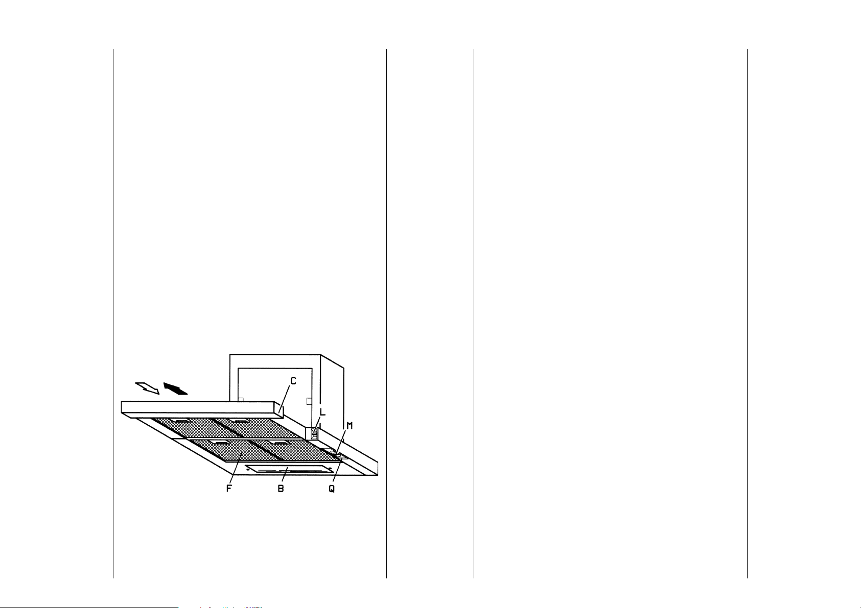
Appliance
description
C = Visor
Q = Controls
M = Motor switch
L = Lighting switch
B = Lighting
F = Metal filter
Electrical connection:
Total absorbed power: 270 W
Motor: 2x126 W
Lighting: 1x18 W
Evacuation ducting 120/125/150 mm Ø.
32
33
Page 5
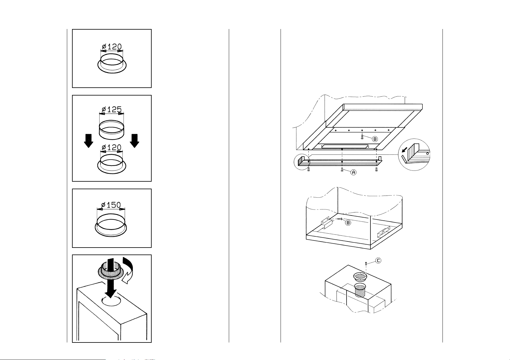
Accessories/installation material
Air outlet
Air outlet 120 mm Ø
Air outlet 125 mm Ø
1 ducting spigot Ø 120mm
1 ring Ø 120-125mm
1 ducting spigot Ø 150mm
1 break-off wall infill spacer to be applied on the lower part of
the cooker hood to cover the hollow space up to the wall
1 venting grille Ø 120mm
2 brackets to fix the cooker hood
3 screws (A)
9 screws (B)
2 screws (C)
34
Air outlet 150 mm Ø
ATTENTION: The installer should ensure that the material
for the connection of the cooker hood to the evacuation
duct or to the upper part of the cabinet is available.
The venting grille can be fitted only on 120 mm Ø ducts.
35
Page 6
Installation
Preparing
the
cabinet
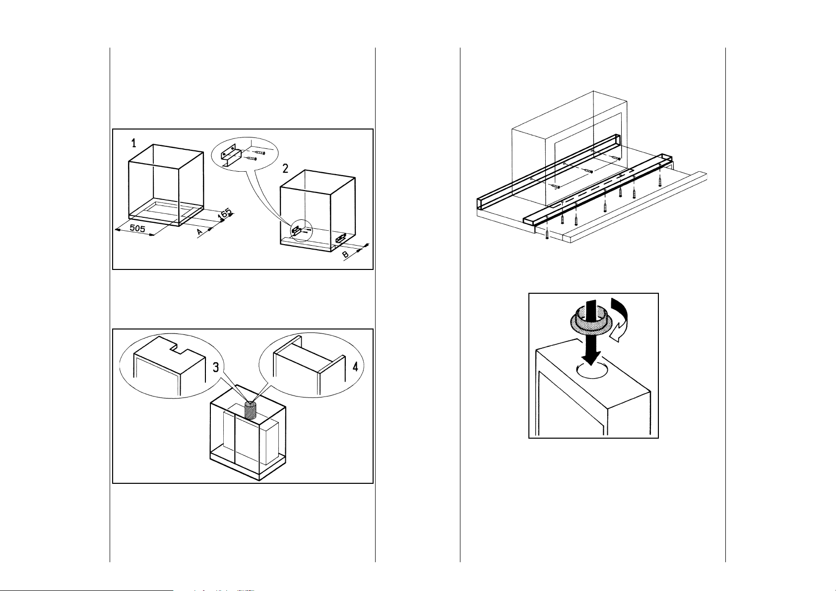
Make a 505 x 165mm hole on the bottom of the cabinet 1).
The measure A must be calculated by the installer according
to the requested alignment between the lower visible part of
the cooker hood and the cabinet. If the cabinet is without bottom
2), fix the two brackets at a distance B of minimum 30mm and
maximum 60mm.
Make a hole on the lower part of the cabinet for the duct outlet
or leave the cabinet open 4).
InstallationBefore carrying out the installation, the wooden transportation
protections screwed on the visor and on the canopy body must
be removed.
Fit the ducting spigot on the upper opening.
Remove the metal filters and ensure that the butterfly quick
fixing clamps are completely open.
If not, rotate the adjustment screws 2 completely.
36 37
Page 7

Installation
Fit the cooker hood in the cabinet until it is well fixed to the
butterfly quick fixing system placed on the lower part of the
cabinet or on the two brackets.
Connection to the evacuation duct may be realised through a
round or flat duct.
Partially tighten the adjustment screws 2 of the butterly quick
fixing system.
The lower visible part of the cooker hood can be adjusted
(max 20mm) for the horizontal alignment with the cabinet.
Partially loosen the four screws fixing the lower part of the
cooker hood to the upper part 1), adjust the lower part of the
cooker hood 2) in the desired position and tighten the screws
definitively.
Definitely fix the cooker hood to the cabinet by tightening the
adjusting screws 2.
Installation
38
Fix the lower part to the cabinet using five supplied screws.
39
Page 8

Front strip
If you wish to replace the factory fitted front strip with a wooden
one or with a front strip made with the same material as the
kitchen, remove the five screws. Remove the front strip.
Fix the new front strip with the central screw before and, later,
fasten the other four screws definitely.
If the cooker hood is to be installed in recirculation mode then
charcoal filters (on request) must be provided.
Fit the charcoal filters ensuring that they click into position correctly.
Recirculation
fitting
The cooker hood can be installed in two different ways:
RECIRCULATION FITTING:
using two charcoal filters to catch the odours and to recirculate
the air back into the kitchen.
EVACUATION FITTING:
(without charcoal filters) to pass contaminated air out through
ducting to the atmosphere.
40 41
Page 9

Recirculation
fitting
Connect a suitable length of ducting to the air outlet on the top
of the cooker hood inside the cabinet. The ducting should be
long enough to project through the hole in the top of the cabinet.
Fit the venting grille over the ducting and screw the grille to the
top using the screws provided. Ensure that the blades in the
grille are angled forwards.
Recycling installation is now completed.
If you wish to install the appliance in evacuation mode, the
charcoal filters are not required.
Ducting
fitting
To remove the charcoal filters, press in the two charcoal filters
catches.
4342
Page 10

Electrical connection
fitting
Replace the metal filters.Evacuation
It is now possible to install the ducting. Attention should be
taken when installing the ducting to choose the shortest possible
run with the minimum number of bends. The use of bends may
cause a loss of air capacity and should be avoided where
possible.
The internal diameter of the ducting should be the same as the
external diameter of the ducting spigot.
Now ducting installation is completed.
Your appliance must be connected to fixed wiring via the use
of a double pole switched fused spur outlet with or without pilot
lamp.
We strongly recommend the appliance is connected by a
qualified electrician who is a member of the NICEIC who will
comply with the IEE and any local regulations.
44
NOTE: The terminology "DOUBLE POLE" means that both the
live and neutral supplies are switched and disconnected at the
same time.
45
Page 11

Safety warnings
The terminations laballed SUPPLY are for connection for the
internal house wiring and the terminations labelled LOAD are
for the appliance.
IMPORTANT - The wires of the mains load supplied with this
appliance are coloured in accordance with the following code:
Blue - Neutral
Brown - Live
As the colours of the flexible cord of this appliance may not
correspond with the coloured markings identifying the terminals
in your plug, poceed as follows:
The wire which is coloured brown must be connected to the
terminal which is marked with the letter L or coloured red.
The wire which is coloured blue must be connected to the
terminal which is marked with the letter N or coloured black.
Never leave the burners of the hob uncovered while the
hood is in use: an excessive heat could damage the
appliance. Open-fire cooktops, such as oil-, gas- and coalfired cooktops, must be avoided.
Never leave frying pans unattended during use as
overheated fat and oils may catch fire.
Polluted oils increase fire hazard.
The overheating can cause fire hazard.
Never do flambé cooking under the cooker hood.
Before carrying out any kind of cleaning or maintenance,
even the replacement of the fluorescent strip light,
disconnect the appliance unplugging the cooker hood or
acting on the mains supply.
The metal filters or the charcoal filters should be cleaned
or replaced as recommended by the manufacturer.
There could be a possible fire hazard in the case of grease
accumulation on the filters.
For the
user
46 47
Page 12

Appliance description/controls
To switch on the cooker hood slide the switch marked M selecting the required fan speed.
The symbols and numbers have the following meaning:
Motor Lighting
M = Motor switch L = Lighting switch
0 = The motor is off 0 = Lighting is off
1 = Low speed 1 = Lighting is on
2 = Medium speed
3 = Top speed
The movement of the visor can be used to switch the appliance
on and off.
ControlsControls
To switch on the worktop lighting slide the switch L to position 1.
48 49
Page 13

Cleaning and maintenance
Metal filters
Before carrying out any kind of maintenance, disconnect the
hood form the mains supply or unplug the appliance.
The metal filters retain grease particles and are used both in
evacuation and recirculation mode.
The metal filters should be cleaned every 4 weeks in the
dishwasher or by hand.
The charcoal filter is to be used only in recirculation mode.
You should use only AEG original filters (see Special Accessories).
The charcoal filter cannot be cleaned or regenerated.
It should be replaced every 8 months if the hood is used normally.
To replace the charcoal filters push the metal retaining clips
inwardly.
To order the spare filters, you should state the reference, the
model and the product number of the cooker hood.
These data are shown on the rating plate inside the hood.
The charcoal filters can be ordered at AEG After Sales Service.
Charcoal
filters
Washing by
hand
Washing in the
dishwasher
50
Leave the metal filter in warm water with mild detergent for one
hour and then rinse with warm water. The operation should be
repeated if necessary. The filter can be refitted after having
ensured it is completely dry.
Put the filters in the dishwasher. Choose the strongest washing
programme, 65° at least. The operation should be repeated if
necessary. Refit the filter after having ensured it is completely
dry.
Use only warm detergent to clean the internal part of the cooker
hood (do not use abrasive cleaners, brushes or scouring
agents).
51
Page 14

Strip light
replacement
(Starter)
A 18W fluorescent strip light ensures the lighting of the worktop.Fluorescent
To replace the fluorescent strip light operate as follows:
Disconnect the hood from the mains supply.
Unplug the hood.
Remove the screw on the plastic terminal near the lighting
diffuser.
Move the glass strip until the opposite end is free.
Pull the glass strip slightly downward.
Move the strip glass toward one side and remove.
Replace the fluorescent strip light.
Fluorescent
strip light
replacement
(Starter)
To replace the starter, remove the inside cover of the lighting
area operating as follows:
Remove the metal filter.
Remove the two screws and turn the inside cover upward.
52 53
Page 15

Special accessories
strip light
(Starter)
General
warnings for
the cleaning
Turn the Starter as illustrated and replace.Fluorescent
Attention: To clean the cooker hood disconnect the appliance from the mains supply.
Do not insert any sharp object in the motor protection
grille.
Clean the outside parts of the cooker hood with mild detergent. Do not use abrasive cleaners, brushes or scouring
agents.
Control panel should be cleaned only with a damp cloth
and mild detergent.
Charcoal filter E. Nr. 610 899 435
KF 7509
Wall box E. Nr. 610 899 004
MKZ
Outside dimensions for the 250x220
hole on the wall 185x210
Evacuation duct E. Nr. 610 899 007
120 mm Ø Aluminium
Evacuation duct E. Nr. 610 899 008
125 mm Ø Aluminium
After Sales Service
There could be a possible fire hazard if the grease filters
are not cleaned or replaced when necessary and according
to these instructions.
54
In case of any enquiries or faults, please call our After Sales
Service (see list of After Sales Centres).
When you call, please state what follows:
1. The model reference
2. The appliance number (E. Nr.)
3. The production number (F. Nr.)
These data are shown on the rating plate inside the hood.
The rating plate is visible once the metal filters have been
removed.
In the interest of technical progress, the manufacturer reserves
the right to make design and colour alterations without prior
notice.
55
Page 16

56
57
Page 17

58
59
Page 18

616063
Page 19

62
Page 20

Bitte geben Sie unserem Kundendienst folgende Angaben bei einer
Störung an:
If your appliance has a fault, please contact our service engineer and
state the following numbers:
E-Nr. 610
F-Nr.
AEG Hausgeräte GmbH
Postfach 1036
D-90327 Nürnberg
© Copyright by AEG
H 259 214 700 - 1294/02 -
4324241 02- 020301
 Loading...