

Page 1

T3SU 300
T3 Service Unit
USER MANUAL
1200217L1 T3SU 300
1200217L2 T3SU 300 with Internal Modem
1200218L1 HSSI DTE Interface Card
1200219L1 V.35 DTE Interface Card
61200217L1-1B
December 1998
Page 2

Trademark Information:
OpenView is a trademark of Hewlett-Packard Company.
Spectrum is a registered trademark of Cabletron.
Netview is a registered trademark of IBM.
901 Explorer Boulevard
P.O. Box 140000
Huntsville, AL 35814-4000
Phone: (256) 963-8000
© 1998 ADTRAN, Inc.
All rights reserved.
Printed in USA.
Page 3

ABOUT THIS MANUAL
This manual is arranged so you can quickly and easily find the informa tion
you need. The following is an overview of the contents of this manual:
• Chapter 1, Introduction, familiarizes you with T3 networks and T3SU 300
highlights and gives a brief explanation of options that may be purchased
for use with the T3SU 300.
• Chapter 2, Installation and Operation , describes the T3SU 300 connectors
(pin assignments are given in Appendix A), provides ins tallation instructions, and explains how to operate your T3SU 300 using the terminal
interface.
• Chapter 3, Configuration, explains how to access the T3SU 300 Configuration menu, describes selections made in the Configuration menus, and
provides a menu tree of all of the a v ailable Configuration options.
• Chapter 4, Status, describes each field of the Status menu.
• Chapter 5, Statistics , expl ains h ow to access statistical information for the
T3SU 300 and describes each field.
• Chapter 6, Diagnostics, explains how to diagnose problems using loopback and BERT tests.
• Chapter 7, Applications, provides examples of some common T3SU 300
applications. This chapter includes network diagrams as well as configuration tables for each example.
• Appendix A provides pinouts for the T3SU 300 connectors.
• Appendix B contains product specifications.
• Appendix C is a list of acronyms and abbreviations used in this document.
• Appendix D is a glossary.
iii
Page 4

Notes provide additional useful information.
Cautions signify informat ion that could prevent service interruption.
Warnings provide information that could prevent damage to the
equipment or endangerment to hum a n life.
IMPORTANT SAFETY INSTRUCTIONS
SAVE THESE INSTRUCTIONS
When using your telephone equipment, please f ollow these basic safety precautions
to reduce the risk of fire, electrical shock, or personal injury:
1. Do not use this product near water, such as near a bath tub, wash bowl, kitchen
sink, laundry tub, in a wet basement, or near a swimm ing pool.
2. Avoid using a telephone (other than a cordless-type) during an electrical storm.
There is a remote risk of shock from lightning.
3. Do not use the telephone to report a gas leak in the vicinity of the leak.
4. Use only the power cord, power supply, and/o r batteries indicated in the manual.
Do not dispose of batteries in a fire. They may explode. Check with local codes
for special disposal instructions.
iv
Page 5

FCC regulations require that the following information be provided in this ma nual:
1. This equipment complies with Part 68 of FCC rules. On the bottom of the equip-
ment housing is a label showing the FCC registrat ion number and ringer equivalence number (REN) for this equipment. If requested, provide this information to
the telephone company.
2. If this equipment causes harm to the telephone network, the telephone company
may temporarily discontinue service. If possible, adva nce notification is given;
otherwise, notification is given as soon as possible. The telephone company will
advise the customer of the right to file a complaint with the FCC.
3. The telephone compan y may make changes in its facilities, equipment, opera-
tions, or procedures that could affect the proper operation of this equipment.
Advance notification and the opportunity to maintain uninterrupted service are
given.
4. If experiencing difficulty with this equipment, please contact ADTRAN for r e pair
and warranty information. The telephone company may require this equipment
to be disconnected from the network until the problem is corrected or it is certain
the equipment is not malfunctioning.
5. This unit contains no user-serviceable parts.
6. An FCC compliant telephone cord with a modular plug is provided with this
equipment. This equipment is designed to be connected to the telephone netw ork
or premises wiring using an FCC compatible modular jack, which is Part 68 compliant.
7. The following information may be required when applying to the local telephone
company for a dial-up line for the V.34 modem:
Service Type REN FIC USOC
Loop Start (V.34) 0.8B/0.4A 02LS2 RJ-11C
8. The REN is useful in determining the quantity of devices you may connect to
your telephone line and still have all of those devices ring when your number is
called. In most areas, the sum of the RENs of all devices should not exceed five.
To be certain of the number of devices you may connect to your line as determined by the REN, call your telephone company to determine the maximum REN
for your calling area.
9. This equipment may not be used on coin service provided by the telephone com-
pany. Connection to party lines is subject to state tariffs. Contact your state public utility commission or corporation commission for informatio n.
v
Page 6

YEAR 2000 COMPLIANCE
All ADTRAN transmission hardware and software products have been tested and
found to be fully compliant with the YEA R 2 00 0 requirements. This is true for all
models and revisions regardless of the date of manufacture or delivery.
Users who wish to independently verify that specific products are in compliance may
contact ADTRAN Technical Support at 1-888-423-8726.
vi
Page 7

FEDERAL COMMUNICATIONS COMMISSION
RADIO FREQUENCY INTERFERENCE STATEMENT
This equipment has been tested and found to comply with the limits for a Class A digital device, pursuant to Part 15 of the FCC Rules. These limits ar e designed to provide
reasonable protection against ha rmful interference w hen the equipment is operated in
a commercial environment. This equipment generates, uses, and can radiate radio frequency energy and, if not installed and used in accordance with the instruction manual, may cause harmful interference to radio frequencies. Operation of this equipment
in a residential area is likely to cause harmful interference in which case the user will
be required to correct the interference at his own expense.
Shielded cables must be used with this unit to ensure compliance with Class A FCC limits.
Changes or modifications to this unit not expressly approved by the party responsible for compliance could void the user's authority to operate
the equipment.
CANADIAN EMISSIONS REQUIREMENTS
This digital apparatus does not exceed the Class A limits for radio noise emissions
from digital apparatus as set out in the interference-causing equipment standard entitled “Digital Apparatus,” ICES-003 of the Department of Communications.
Cet appareil nuerique respecte les limites de bruits radioelectriques applicables aux
appareils numeriques de Class A prescrites dans la norme sur le materiel brouilleur:
“Appareils Numeriques,” NMB-003 edictee par le ministre des Communications.
vii
Page 8

CANADIAN EQUIPMENT LIMITATIONS
Notice: The Canadian Industry and Science Canada label identifies certified equipment. This certification means that the equipment meets certain telecommunications
network protective, operational, and safety requi rements. The Department does not
guarantee the equipment will operate to the user’s satisfaction.
Before installing this equipment, users should ensure that it is permissible to be con nected to the facilities of the local telecommunications company. The equipment must
also be installed using an acceptable methods of connection. In some cases, the company’s inside wiring associated with a single line individual service may be extended
by means of a certified connector assembly (telephone extension cord). The customer
should be aware that compliance with the above limitations may not prevent degradation of service in some situations.
Repairs to certified equipment should be made by an authorized Canadian maintenance facility designated by the supplier. Any repairs or alterations made by the user
to this equipment, or equipment malfunctions , may give the telecommunications
company cause to request the user to disconnect the equipment.
Users should ensure for their own protection that the electrical ground connections of
the power utility, telephone lines and internal metallic water pipe system, if present,
are connected together. This precaution may be particularly important in rural areas.
Users should no t a ttempt to make suc h co nne ction s th emse lve s, bu t sho uld
contract the appropriate electric inspection authority, or an electrician, as
appropriate.
The Load Number (LN) assigned to each terminal device denotes the percentage of
the total load to be connected to a telephone loop which is used by the device, t o prevent overloading. The termination on a loop may consist of any combination of
devices subject only to the requirement that the total of the Load Numbers of all
devices does not exceed 100.
viii
Page 9

Table of Contents
Chapter 1. Introduction.....................................................................................................1-1
Product Overview ...............................................................................................................1-1
T3 Overview ......................................................................................................................... 1-2
SNMP .................................................................................................................................... 1-2
TELNET ................................................................................................................................ 1-3
Interface Option Cards ....................................................................................................... 1-4
HSSI Card............................................................ ..... ..................................................... 1-4
V.35 Card....................................................................................................................... 1-4
Warranty and Customer Service .......................................................................................1-5
Chapter 2. Installation and Operation...........................................................................2-1
Unpack, Inspect, Power Up ...............................................................................................2-1
Receiving Inspection.......................................... ..... ...... ............................................... 2-1
Installing the Unit ................................................................................................................ 2-2
Rackmount Installation............................................................................................... 2-2
Desktop Installation..................................................................................................... 2-3
Rear Panel ............................................................................................................................. 2-3
DTE Port Interface Card Slots.................................................................................... 2-4
Alarm Connector.......................................................................................................... 2-4
DTE Port 1 (HSSI Interface)........................................................................................ 2-5
Auxiliary Port............................................................................................................... 2-5
LAN Port....................................................................................................................... 2-6
DS3 Interface............................................................ ...... ............................................... 2-6
Front Panel ........................................................................................................................... 2-6
Control Port .................................................................................................................. 2-6
LED Descriptions......................................................................................................... 2-9
Chapter 3. Configuration..................................................................................................3-1
DS3 Network ................................................. ....................................................................... 3-2
DS3 Framing........................................... ...... ................................................................ 3-3
61200217L1-1 T3SU 300 User Manual ix
Page 10

Table of Contents
Line Length ................................................................................................................... 3-3
DS3 Timing.......................................... ...... ..... ............................................................... 3-3
DS3 Scrambler............................................................................................................... 3-4
Data Link....................................................................................................................... 3-4
Remote Auto-Configuration....................................................................................... 3-4
DTE Ports ..............................................................................................................................3-4
Port Selections 1-4 ........................................................................................................ 3-5
Timed Profiles............................................................................................................. 3-10
System Management .........................................................................................................3-11
Local IP Address ........................................................................................................ 3-12
Subnet Mask................................................................................................................ 3-12
Gateway IP Address.................................................................................................. 3-13
Remote IP Address..................................................................................................... 3-13
IP Security ................................................................................................................... 3-13
IP Hosts........................................................................................................................ 3-13
Management Port....................................................................................................... 3-13
Auxiliary Port Mode.................................................................................................. 3-13
Modem Mode ............................................................................................................. 3-14
Auxiliary Port Baud Rate.......................................................................................... 3-14
Read Community Name ........................................................................................... 3-14
Write Community Name .......................................................................................... 3-15
Trap IP Addresses...................................................................................................... 3-15
Trap Generation ......................................................................................................... 3-15
Password ..................................................................................................................... 3-18
Unit ID ......................................................................................................................... 3-19
Terminal Timeout....................................................................................................... 3-19
Date/Time................................................................................................................... 3-19
Alarm Relay ................................................................................................................ 3-19
Dialup Options......................................... ..... ...... ....................................................... 3-19
Utilities ................................................................................................................................ 3-22
Save Configuration ............................................................................................................3-24
Chapter 4. Status................................................................................................................. 4-1
Network Port ........................................................................................................................4-2
DS3 Framing ....................................... ...... ..... ............................................................... 4-2
Network State............................................................................................................... 4-2
Alarm State.................................................................................................................... 4-2
Data Link State.............................................................................................................. 4-3
Remote State.................................................................................................................. 4-3
DTE Ports ..............................................................................................................................4-5
Interface Type..................................... ...... ..... ............................................................... 4-5
x T3SU 300 User Manual 61200217L1-1
Page 11

Table of Contents
Port Status..................................................................................................................... 4-5
Bandwidth..................................................................................................................... 4-6
DTE Leads..................................................................................................................... 4-6
Chapter 5. Statistics............................................................................................................5-1
Viewing Statistical information ............................................... ..... ...... ............................... 5-1
Alarm History............................................................................................................... 5-2
Performance Parameters.............................................. ...... ......................................... 5-4
Chapter 6. Diagnostics ......................................................................................................6-1
DS3 ................................................................................................................................. 6-2
DTE Ports 1-4................................................................................................................ 6-5
BERT Configuration .................................................................................................... 6-9
Chapter 7. Applications .................................................................................................... 7-1
Single Port Full T3 Bandwidth ..........................................................................................7-1
Point-to-Point Multiport Application .............................................................................. 7-3
Fractional T3 Carrier Application ..................................................................................... 7-5
Remote SNMP Management Application .......................................................................7-7
Appendix A. Pinouts ........................................................................................................A-1
Appendix B. Specifications Summary...........................................................................B-1
Appendix C. Acronyms/Abbreviations.........................................................................C-1
Appendix D. Glossary......................................................................................................D-1
61200217L1-1 T3SU 300 User Manual xi
Page 12

Table of Contents
xii T3SU 300 User Manual 61200217L1-1
Page 13

List of Figures
Figure 2-1. T3SU 300 Rear View.......................................................................................2-4
Figure 2-2. T3SU 300 Front Panel......................................................................................2-6
Figure 2-3. Terminal Main Menu......................................................................................2-7
Figure 3-1. Configuration Main Menu............................................................................3-2
Figure 3-2. DS3 Network Configuration Menu .............................................................. 3-3
Figure 3-3. DTE Ports Menu ......................................................... ...... ............................... 3-5
Figure 3-4. Port Configuration Menu (with V.35 interface card installed)..................3-6
Figure 3-5. Timed Profiles Screen.................................................................................... 3-10
Figure 3-6. Example of a Profile C onfiguration Menu..................................................3-11
Figure 3-7. System Management Configuration Menu (1 of 2) ..................................3-12
Figure 3-8. Trap Generation Menu.................................................................................. 3-15
Figure 3-9. System Management Configuration Menu (2 of 2) ..................................3-18
Figure 3-10. Dialup Options Menu........................ .........................................................3-20
Figure 3-11. System Utilities Menu................................................................................. 3-23
Figure 3-12. T3SU 300 Configuration Menu Tree ......................................................... 3-25
Figure 4-1. Status Menu......................................................................................................4-1
Figure 5-1. Main Local Statistics Menu Screen................................................................5-2
Figure 5-2. Current Alarm Count Screen ......................................................................... 5-3
Figure 5-3. 24-Hour Alarm History Screen......................................................................5-3
Figure 5-4. Network Statistics Menu for Current 15-Mi n ute Interval.........................5-5
Figure 5-5. Network Port Statistics 24-Hour History Screen........................................ 5-6
Figure 5-6. Network Port Statistics Menu (24-Hour Totals).......................................... 5-7
Figure 6-1. Diagnostics Main Menu..................................................................................6-2
Figure 6-2. DS3 Diagnostics Menu....................................................................................6-3
Figure 6-3. DS3 Payload Loopback Test........................................................................... 6-4
61200217L1-1 T3SU 300 User Manual xiii
Page 14

List of Figures
Figure 6-4. Line Loopback Test..........................................................................................6-4
Figure 6-5. DTE Port Diagnostics Menu...........................................................................6-5
Figure 6-6. Payload Loopback Test ...................................................................................6-6
Figure 6-7. Payload BERT Test...........................................................................................6-7
Figure 6-8. DTE Loopback Test..........................................................................................6-7
Figure 6-9. Payload and DTE Loopback Test...................................................................6-8
Figure 6-10. BERT Pattern Menu.....................................................................................6-10
Figure 7-1. Single Port Application...................................................................................7-2
Figure 7-2. Multiport Application.....................................................................................7-3
Figure 7-3. Fractional Application ....................................................................................7-5
Figure 7-4. Remote Management Application................................................................7-7
xiv T3SU 300 User Manual 61200217L1-1
Page 15

List of Tables
Table 3-1. Near End Alarm Trap Descriptions ................................................. ...... ...... 3-16
Table 3-2. Far End Alarm Trap Descriptions .............................................................. 3-16
Table 3-3. MIB II Standard Trap Descriptions .............................................................. 3-17
Table 3-4. Network Test Trap Descriptions............................................................. ..... .3-17
Table 3-5. DTE Port Trap Description............................................................................ 3-18
Table 4-1. LA and LB Leads...............................................................................................4-7
Table 7-1. Configuration Example for Single Port Full T3 Bandwidth Application . 7-2
Table 7-2. Configuration Example for Multiport Application...................................... 7-4
Table 7-3. Configuration Example for Fractional T3 Application................................7-6
Table 7-4. Configuration Example for Remote Management Applicati on ................. 7-8
Table A-1. Control and Auxiliary Port Pin Assignments.............................................A-1
Table A-2. HSSI Interface Pin Assignments ...................................................... ............. A-2
Table A-3. V.35 Interface Card Pin Assignments .......................................................... A-3
Table A-4. LAN Port Pin Assignments...........................................................................A-4
61200217L1-1 T3SU 300 User Manual xv
Page 16

List of Tables
xvi T3SU 300 User Manual 61200217L1-1
Page 17

Chapter 1 Introduction
PRODUCT OVERVIEW
The T3SU 300 is a multiport DSU/CSU (data servi ce unit/channel
service unit) that provides access to T3 services. The unit pr ovides a
cost-effective, versatile approach for migrating T1 services to T3.
The TDM (time division multiplexer) multiport design allows you
to share the cost of a T3 line between multiple applications. This
unit maximizes the use of T3 services, providing up to four data
ports capable of transmitting and receiving high-capacity, real time
data.
A HSSI (high speed serial interface) port is built in along with three
slots which accept additional HSSI or V.35 interface cards. The HSSI
interfaces support rates between 75 kbps and 44.2 Mbps in 75 kbps
increments. The high speed V.35 interface option supports rates up
to 10 Mbps in increments of 75 kbps .
Embedded SNMP (simple network management protocol) and
TELNET are available through either a SLIP/PPP or a 10baseT
ethernet port. Through the Management Information Base II(MIB
II), RFC 1407 standards, and an ADTRAN enterprise MIB, the
T3SU 300 can be configured, monitored, and diagnosed using
standard SNMP network management programs such as Hewlett
Packard’s HP OpenView™, IBM’s Netview™, and Cabletron’s
Spectrum™.
Complete configuration, diagnostics, and performance monitoring
are available through SNMP, TELNET, or a VT 100 terminal
interface. This connection can be made via ethernet, a local EIA-232
61200217L1-1 T3SU 300 User Manual 1-1
Page 18

Chapter 1. Introduction
link, or through the built-in V.34 modem (1200217L2 only).
Advanced dial-out on trap capabilities through the built-in modem
allow the T3SU 300 t o co ntact r emo te ho sts and al ert them to DS X-3
network conditions (without dedicated management connections).
The T3SU 300 is designed for either desktop use or installation in a
19-inch rack.
The major features or the T3SU 300 are as follows:
• Full feature multiport T3 DSU/CSU
• Maximum of four user data ports (HSSI or high speed V.35)
available
• Automatic or manual remote configuration
• Embedded SNMP and TELNET management through 10baseT
ethernet or SLIP/PPP
• Detailed performance monitoring for local and remote unit s
• Simplified configuration through detailed VT 100 terminal
menu structure
• Optional integrated V.34 modem for dial-up and dial-out
access (product version 1200212L2 only)
• Standard 5-year warranty
T3 OVERVIEW
T3 provides the same bandwidth as 28 T1s and is used to
interconnect high-speed bridges, routers, fr ont-end pr ocessors, a nd
data terminal equipment (DTE). T3 service plays a major role in
Internet backbones and public organizations needing broad
bandwidth for WAN (wide area network) connectivity.
SNMP
The T3SU 300's embedded SNMP feature allows the unit to be
accessed and controlled by a network manager through either the
auxiliary (AUX) control port or the 10baseT local area network
1-2 T3SU 300 User Manual 61200217L1-1
Page 19

Chapter 1. Introduction
(LAN) port. The T3SU 300 supports th e M IB-II stan dard, RFC 1213,
and the ADTRAN Enterprise Specific MIB.
MIB files are available from ADTRAN in the support section of the
ADTRAN Web page at www.adtran.com.
The term SNMP broadly refers to the message protocols used to
exchange information between the network m anagement system
(NMS) and the managed devices, as well as to the structure of
device management databases. SNMP has three basic components:
Network Manager
Control programs that collect, contr ol, and present data pertinent to
the operation of the network devices. These program s reside on a
network management station.
Agent
Control program that resides in every network device. This
program responds to queries and commands from the network
manager, returns requested information or invokes configuration
changes initiated by the manager, and sends unsolicited traps to the
manager.
MIB
Industry standard presentation of all status and configuration
parameters supported by a network device.
TELNET
TELNET provides a password-protected, remote login facility to
the T3SU 300 that allows a remote user to control the T3SU 300
through the terminal menus. Only one TELNET session may be
active at a time.
61200217L1-1 T3SU 300 User Manual 1-3
Page 20

Chapter 1. Introduction
INTERFACE OPTION CARDS
Optional interface cards may be purchas ed to equip the T3SU 300
with up to three additional ports. Both HSSI and V.35 interface
cards are available.
HSSI Card
The optional HSSI card plugs into one of the three card slots on the
rear of the T3SU 300. With optional HSSI cards instal led, the total
44.2 Mbps bandwidth of the T3 can be divi ded among the total
number of ports to provide multiple data channels over the T3. The
total bandwidth of the T3 can be divided among the available ports
in any fashion, as long as the divisions are on 75 kbps boundaries.
The HSSI card can be hot inserted or swapped. When it is inserted
in a slot on the rear panel and its faceplate is secured to the rear
panel of the T3SU 300 with the integral thumb screws, a PCMCIA
type connector on the card mates with a compatible connector on
the main board of the T3SU 300. A standard 50-pin HSSI connector
is then available for DTE connections. See the section DTE Port
Interface Card Slots on page 2-4 for more information on installing
option cards.
V.35 Card
The optional V.35 card plugs into the card slots on the rear of the
T3SU 300 to provide a V.35-type DTE interface. Operation of the
V.35 card is similar to that of the HSSI card except that the
maximum bandwidth of the V.35 card is limited to 10 Mbps.
Like the HSSI card, the V.35 card can be hot inserted or s wapped,
and it installs just as the HSSI card does. Instead of the standard
HSSI connector, this card contains a standar d 34- pin V.35 connector
for DTE connections. See the section DTE Port Interface Card Slots on
page 2-4 for more information on installing option cards.
1-4 T3SU 300 User Manual 61200217L1-1
Page 21

WARRANTY AND CUSTOMER SERVICE
ADTRAN will replace or repair this product within five years from
the date of shipment if it does not meet its published specification s
or fails while in service. For detailed warranty, repair, and return
information refer to the ADTRAN Equipment Warranty and Repair
and Return Policy Procedure.
Return Material Authorization (RMA) is requir ed prior to returning
equipment to ADTRAN.
For service, RMA requests, or further information, contact one of
the numbers listed on the inside back cover of this manual.
Chapter 1. Introduction
61200217L1-1 T3SU 300 User Manual 1-5
Page 22

Chapter 1. Introduction
1-6 T3SU 300 User Manual 61200217L1-1
Page 23

Chapter 2 Installation and Operation
UNPACK, INSPECT, POWER UP
Receiving Inspection
Carefully inspect the T3SU 300 for any damage that may have
occurred in shipment. If damage is suspected, file a claim
immediately with the carrier and contact ADTRAN Technical
Support (see the back cover of this manual). Keep the original
shipping container to use for future shipment or verification of
damage during shipment.
ADTRAN Shipments Include
The following items are included in ADTRAN shipments of the
T3SU 300:
• T3SU 300 unit
• User manual
• An 8-position modular to 8-position modular cable (two of
these cables are included in the 1200217L1 version)
• An 8-position modular to DB-25 female connector
• An 8-position modular to DB-25 male connector (1200217L1
version only)
• A 4-position modular to 4-position modular cable (1200217L2
version only)
• Mounting ears for 19-inch rack insta llation
• Rubber feet for stand-alone use
61200217L1-1 T3SU 300 User Manual 2-1
Page 24

Chapter 2. Installation and Operation
The ADTRAN T3SU 300 MIB is available in the support section of the
ADTRAN Web page at www.adtran.com.
Customer Provides
The customer provides an interface cable for each port used. Each
cable should be either HSSI or V.35.
Power Up
Each T3SU 300 unit is provided with a captive eight-foot power
cord, terminated by a three-prong plug which connects to a
grounded 115 VAC power receptacle.
Power to the T3SU 300 must be provided from a grounded 115 VAC,
60 Hz receptacle.
INSTALLING THE UNIT
The T3SU 300 can be used as a desktop stand-alone device or
mounted into a standard 19-inch equipment rack. See the section
Establishing Terminal Connection on page 2-6 for information on
terminal configuration.
Rackmount Installation
Follow these steps to mount your unit into a rack:
1. Install the 19-inch rackmount flanges on each side of the
T3SU 300 enclosure at one of the three avai lab le positions.
Be sure to install the flanges with the screws provided.
2-2 T3SU 300 User Manual 61200217L1-1
Page 25

2. After the flanges have been installed, position the T3SU 300 at
the correct location within the rack and secure the mounting
flanges to the mounting rails of the rack.
3. Make all network, DTE, and power connections to the rear of
the unit.
4. Using the 8-position modular to DB-25 female connector and
the 8-position modular to 8-position modular cable, connect a
VT 100 terminal device to the CONTROL interface jack on the
front panel of the unit.
Desktop Installation
Follow these steps when using your T3SU 300 as a desktop unit:
1. Affix the four adhesi ve-backed rubber feet to the bottom of the
unit, one in each of the four corners. The feet should be placed
approximately one inch from the front or back and one inch
from the sides of the unit
2. Make all network, DTE, and power connections to the rear of
the unit.
3. Using the 8-position modular to DB-25 female connector and
the 8-position modular to 8-position modular cable, connect a
VT 100 terminal device to the CONTROL interface jack on the
front panel of the unit.
Chapter 2. Installation and Operation
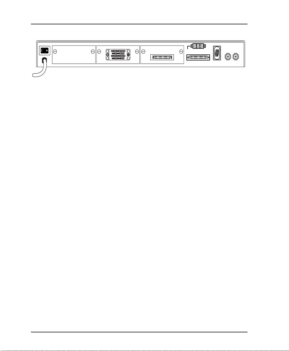
REAR PANEL
The T3SU 300 is equipped with three option card slots, a built-in
HSSI interface, an alarm output terminal block, an auxiliary (AUX)
port, a LAN port, and a DS3 interface. Pin assignments for
connectors are given in the appendix Pinouts on page A-1. The
T3SU 300 rear panel is shown in Figure 2-1.
61200217L1-1 T3SU 300 User Manual 2-3
Page 26
Chapter 2. Installation and Operation
BFLRVZDDJJNN
T
X
DJN
LL
FF
BB
AEK
PUY
CC
HH
MM
S
C
H
M
W
AAEEKK
DTE PORT 4
V.35 INTERF A CE
DTE PORT 3
Item Function
On/Off Switch
115 VAC Connection
DTE Ports 2-4
Alarm
DTE Port 1
Aux
LAN
DS3 Interface
DTE Port Interface Card Slots
The T3SU 300 rear panel has three card slots for the installation of
optional interface cards. To ins ert cards, perform the following
procedure:
NC COM NO
ALARM
HSSI INTERFACE
DTE PORT 2 DTE PORT 1
AUX
LAN
DS3 INTERFACE
RX IN TX OUT
On/off control
Power connection
Interface option card slots
NC/NO relay contacts
Integral HSSI interface
Function depends on product
version (see page 2-5)
10baseT LAN connection
T3 service connection
Figure 2-1. T3SU 300 Rear View
1. Remove blank slot cover from the rear of the T3SU 300.
2. Slide the card into the corresponding rear slot until the card
panel is flush with the T3SU 300 chassis.
3. Push in thumbscrews and turn clockwise to secure the card and
ensure proper connection to the main board of the T3SU 300.
Alarm Connector
The alarm connector is a three-posi tion, screw-type terminal block
that is connected to the three contacts of a Form C-type relay on the
main board of the T3SU 300. This relay is activated any time the
T3SU 300 detects an alarm condition on the T3 network interface.
2-4 T3SU 300 User Manual 61200217L1-1
Page 27

The alarm function can be disabled through the
C
selection of the
ONFIGURATION
DTE Port 1 (HSSI Interface)
DTE port 1 is a built-in HSSI port that resides on the main board of
the T3SU 300. The bandwidth of this port is configurable from 75
kbps to 44.2 Mbps in 75 kbps increments. When a single application
requires the full 44.2 Mbps of bandwidth, the T3SU 300 does not
have to be equipped with additional port cards.
Auxiliary Port
The auxiliary (AUX) port is an 8-pin modular jack located on the
rear panel of the T3SU 300. The function of this port differs,
depending on which version of the T3SU 300 you have (1200217L1
or 1200217L2).
For the 1200217L1 product, this port provides a DTE-type, EIA-232
asynchronous serial port. This port can be connected to a VT 100
terminal or to a device running SLIP or async PPP. This port can
also connect to an external modem to provide dialup VT 100, SLIP,
or PPP. This port’s mode and baud rate are selected in the
M
ANAGEMENT
portion of the
Chapter 2. Installation and Operation
menu.
C
ONFIGURATION
A
menu.
LARM RELAY
S
YSTEM
For the 1200217L2 product, the AUX port pr ovides a telephone line
(POTS) connection for the internal V.34 modem.
For both versions of the product, the T3SU 300 can be configur ed as
a dial-in host and also as a dial-out-on-TRAP device (meaning that
the unit dials out to a specified host to report error conditions).
Configuration for both the external (L1) and internal (L2) modem
D
parameters is done in the
M
ANAGEMENT
C
ONFIGURATION
(
61200217L1-1 T3SU 300 User Manual 2-5
portion of the
S
->
IALUP OPTIONS
C
ONFIGURATION
YSTEM MANAGEMENT
menu under the
menu
D
IALUP OPTIONS
->
S
YSTEM
).
Page 28
Chapter 2. Installation and Operation
LAN Port
The LAN port is an 8-pin modular connector that provides a
10baseT ethernet LAN interface. This LAN interface is used for
SNMP and TELNET control.
DS3 Interface
The DS3 network interface is a full-duplex circuit provided by two
BNC coaxial cable connections. The receive data from the network
is connected to the RX (In) connector while the transmit data from
the T3SU 300 is connected to the TX (Out) connector.
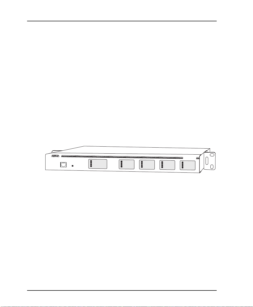
FRONT PANEL
The T3SU 300 faceplate is shown in Figure 2-2. Descriptions of each
part of the front panel follow.
CONTROL
REMOTE
ACTIVE
IN SERVICE
IN TEST
ALARM
LOS
NETWORK
IN SERVICE
IN TEST
ALARM
LOS
DTE PORT 1
IN SERVICE
IN TEST
ALARM
LOS
DTE PORT 2
IN SERVICE
IN TEST
ALARM
LOS
DTE PORT 3
T3SU 300
IN SERVICE
IN TEST
ALARM
LOS
DTE PORT 4
Figure 2-2. T3SU 300 Front Panel
Control Port
The T3SU 300 has an 8-pin modular jack labeled CONTROL. The
control port prov ides connection to a VT 100 EIA-232 compatible
interface.
Establishing Terminal Connection
To control the T3SU 300 using a VT 100 terminal, follow this
procedure:
1. Configure the VT 100 terminal for 9600 baud, 8-bit characters,
no parity, and one stop bit (9600, 8N1).
2-6 T3SU 300 User Manual 61200217L1-1
Page 29

Chapter 2. Installation and Operation
2. Using the ADTRAN-provided terminal interface cable adapter ,
connect the DTE port of a terminal to the 8-pin modular jack
labeled
Control
on the front panel of the T3SU 300.
3. Initialize the terminal session.
4. Press Enter repeatedly until the password prompt appears.
5. Enter the password. The factory default password is adtran.
M
AIN
The
menu appears. See Figure 2-3.
6. Make selections by entering the number corresponding to the
chosen parameter. Press ESC to return to the previous screen.
End a terminal session by selecting
L
OGOUT
from the
M
AIN
menu or by pressing Ctl-C at any time.
Figure 2-3. Terminal Main Menu
Navigating Within the Menus
Navigate within the T3SU 300 termina l menus using the following
procedures:
61200217L1-1 T3SU 300 User Manual 2-7
Page 30

Chapter 2. Installation and Operation
If you want to... Press...
select an item the number corresponding to your
choice, and then press the
key.
Enter
scroll between screens
within the same selection
return to the previous
menu
end the terminal session
refresh the display
The T3SU 300
M
AIN
menu consists of the following sections:
the up and down arrow keys. Additional screens are available when
<up> or <down> is displayed in the
right-hand side of the menu.
the
Ctl-C
Ctl-R
ESC
.
.
key.
Status
This selection provides status information on the Network and
DTE ports. See the chapter Status on page 4-1 for more information.
Statistics
This selection provides statistical information for the Network port.
See the chapter Statistics on page 5-1 for more information.
Configuration
C
ONFIGURATION
The
menu is used to set network, DTE, and system
management parameters. See the chapter Configuration on page 3-1
for more detailed information.
Diagnostics
D
IAGNOSTICS
The
menu is used to perform loopback and BERT
tests. See the chapter Diagnostics on page 6-1 for more detailed
information.
Remote Login
R
EMOTE LOGIN
The
selection allows you to conf igure the remote
T3SU 300. The remote unit’s password is required at login. The
D
ATALINK
option (in the
DS3 N
ETWORK CONFIGURATION
menu)
must be enabled in order to perform remote configuration.
2-8 T3SU 300 User Manual 61200217L1-1
Page 31

Logout
L
OGOUT
The
system. Password entry is required before a new session can begin.
LED Descriptions
The T3SU 300 has LED status indicators for remote access, the
network port, and for each individual DTE port. These LEDs are
identified as follows:
Remote Active
This LED is solid when a remote configuration session is taking
place through a TELNET session or from the remote end T3SU 300.
It flashes when the unit is being accessed locally through the front
Control
panel
Network LEDs
In Service
This LED is active when a valid signal is being received on the DS3
interface.
Chapter 2. Installation and Operation
selection ends the terminal session and logs out of the
port.
In Test
This LED is active when the network interface has been put in
loopback by the service provider.
Alarm
This LED is active when the DS3 receive signal contains framing
errors, the yellow alarm is received from the far end unit, or other
alarm messages are received from the network.
LOS
This LED is active when no receive signal from the network is
detected on the Rx (in) circuit.
DTE Port LEDs
Status
This LED indicates the following conditions:
61200217L1-1 T3SU 300 User Manual 2-9
Page 32

Chapter 2. Installation and Operation
LED Condition
Off No option card is installed.
Flashing green Interface is available but not configured.
On green Interface is available and configured.
On red DTE fault condition (for HSSI interface, no clock
On yellow For HSSI interface, terminal available (TA) sig-
In Test
This LED is active when the DTE interface is in a loopback
condition or is performing a BERT test.
TD
This LED is active when the T3SU 300 DTE port is transmitting
data.
RD
This LED is active when the T3SU 300 DTE port is receiving data.
from DTE).
nal inactive.
2-10 T3SU 300 User Manual 61200217L1-1
Page 33

Chapter 3 Configuration
The T3SU 300 can be configured locally and remotely. Local
configuration is accomplished through a 10baseT ethernet
connection, a SLIP/PPP port, or a VT 100 terminal. Remote
configuration can take place through the T3 datalink using a local
T3SU 300.
C
ONFIGURATION
The
relating to specific interfaces or functions:
DS3 N
ETWORK
DTE P
ORTS
S
YSTEM MANAGEMENT
U
TILITIES
S
AVE CONFIGURATION
The Main configuration terminal menu is shown in Figure 3-1. The
complete configuration menu tree is given at the end of this chapter
in Figure 3-12. Detailed descriptions of each individual menu
parameter are given in the following sections. These sections are
divided by the five submenus:
P
ORTS
(page 3-4),
(page 3-22), and
menu consists of the following submenus
S
YSTEM MANAGEMENT
S
AVE CONFIGURATION
DS3 N
ETWORK
(page 3-2),
(page 3-11),
(page 3-24).
U
TILITIES
DTE
61200217L1-1 T3SU 300 User Manual 3-1
Page 34

Chapter 3. Configuration
DS3 NETWORK
Figure 3-1. Configuration Main Menu
Select
1 DS3 N
ETWORK
to access the network configuration
parameters. Configure the T3SU 300 network settings to match the
T3 signal received from the service provider. During remote
DS3 N
configuration, this menu is read-only. The
C
ONFIGURATION
DS3 N
ETWORK
3-2 T3SU 300 User Manual 61200217L1-1
menu is shown in Figure 3-2. Descriptions of the
fields follow the figure.
ETWORK
Page 35

DS3 Framing
Chapter 3. Configuration
Figure 3-2. DS3 Network Configuration Menu
Set the framing format to match the format of the receive signal at
the network interface. C-bit parity and M13 framing formats are
supported.
Line Length
Set the line length to reflect the physical length of the DS3 network
line. Set to
L
ONG
if the cabling distance exceeds 50 feet; set to
S
HORT
if the distance is less than 50 feet.
DS3 Timing
L
Set the timing to
network; set to
for the circuit. In most cases, the unit should be configured for
L
OOP
timing.
61200217L1-1 T3SU 300 User Manual 3-3
OOP
if the T3SU 300 is to derive timing from the
L
OCAL
if the unit is to be the master timing source
Page 36

Chapter 3. Configuration
DS3 Scrambler
Enable this option to scramble the DS3 payload data. This prevents
certain transport equipment from falsely reporting alarms.
Data Link
E
Set to
NABLE
to allow for remote configuration. When enabled, the
T3SU 300 provides a chan nel between th e local and the r emote DSU
for point-to-point remote configuration.
Remote Auto-Configuration
This feature allows one T3SU 300 (set to
relay its DTE port bandwidth configuration to a seco nd unit (set to
S
LAVE
). If desired, the feature can be disabled by either unit.
DTE PORTS
M
ASTER
) to automatically
ORTS
ETWORK
menu allows you to select a port to configure. If
is set to
R
EMOTE AUTO CONFIGURATION
->
T
IMED PROFILES
, is available. See Figure 3-3. This
M
ASTER
C
ONFIGURATION
(
M
ASTER
->
),
DTE P
The
R
EMOTE ACCESS CONFIGURATION
DS3 N
->
then a fifth option,
option allows you to set up timed profiles specifying bandwidth
allocation for all four ports.
Configuration selections for the individual ports are described in
T
the following section. A more in-depth description of
P
ROFILES
3-4 T3SU 300 User Manual 61200217L1-1
is on page 3-10.
IMED
Page 37

Chapter 3. Configuration
Figure 3-3. DTE Ports Menu
Port Selections 1-4
DTE P
Select
configuration parameters. Configure each DTE port to be
compatible with the DTE equipment attached to it. A
C
ONFIGURATION
of the individual fields follow the illustration.
61200217L1-1 T3SU 300 User Manual 3-5
1, 2, 3
ORT
menu example is shown in Figure 3-4. Descriptions
, or 4 to access the following port
P
ORT
Page 38

Chapter 3. Configuration
Figure 3-4. Port Configuration Menu (with V.35 interface card installed)
Interface Type
This read-only status field shows the interface type of the selected
port (HSSI or V.35).
Port Status
This read-only status field displays one of the following messages
to show the port status of the selected port:
Inactive
P
The port is installed, but idle. Activate a port through the
S
TATE
field of this menu.
ORT
Active
The port has been configured and is passing data.
3-6 T3SU 300 User Manual 61200217L1-1
Page 39

Port State
Nx75k Blocks
Chapter 3. Configuration
Waiting
The port has been configured and is waiting for the DTE to issue
the appropriate handshaking signals. For the HSSI interface, the
terminal equipment available (TA) signal must be asserted by the
DTE. For V.35, DTR is required if the TR field in this menu is set to
I
DLE WHEN OFF
; otherwise, DTR is ignored.
Error
An error condition such as loss of transmit clock has occurred.
Not Installed
An interface card is not installed in the selected port. If a port is not
installed, the remainder of the
P
ORT CONFIGURATION
menu does not
appear.
D
If a port is installed but not currently in use, set to
E
NABLED
to activate an installed port.
ISABLED
. Set to
This field determines the amount of bandwidth allocated to the
selected port. For a HSSI interface, the selections are from 1-588
(yielding a bandwidth of 75.2 kbps to 44.2 Mbps). For a V.35
interface, the selections are from 1-140 (yielding a bandwidth of
75.2 kbps to 10.5 Mbps). Changes to this field do not take effect
A
until
PPLY SETTINGS
is selected.
Port Bandwidth
This read-only status field shows the amount of bandwidth that
N
will be available if the selection made in the
X75K BLOCKS
field is
applied.
Unallocated 75k blocks
This read-only status field shows the number of 75k blocks of
bandwidth not already allocated to the four ports.
Apply Settings
Select this field after making all configuration changes for the
selected port. The changes are then applied to the unit immediately.
61200217L1-1 T3SU 300 User Manual 3-7
Page 40

Chapter 3. Configuration
CS
TR
Applying the settings briefly affects all ports of the T3 SU 300. You
P
may cancel changes made to the current
ORT CONFIGURATION
menu by pressing the ESC key.
Selects the control mode for the clear to send (CS) lead. This field
only appears if a V.35 interface card is installed in the selected port.
Forced On
The CS lead remains on and request to send (RS) is ignored as long
as the unit is synchronized and able to pass data.
Follow RS
The CS state matches the RS state.
Selects the T3SU 300’s response to the data terminal ready (TR)
lead. This field only appears if a V.35 interface option card is
installed in the selected port.
Ignored
The T3SU 300 ignores the state of the TR lead.
Idle When Off
The T3SU 300 suspends traffic on the selected port if the TR lead is
off.
SR
Selects the control mode for the data set ready (SR) lead. This field
only appears if a V.35 interface card is installed in the selected port.
Forced On
The SR control lead rema ins on regardless of the state of the
network.
Off When OOS/OOF
The SR control lead remains on unless the T3SU 300 receives an out
of service/out of f rame (OOS/OOF) condition from the network.
Off When Test
The SR lead remains on except when the T3SU 300 is executing a
test.
3-8 T3SU 300 User Manual 61200217L1-1
Page 41

CD
Transmit Clock
Chapter 3. Configuration
Off When OOS/OOF or Test
The SR lead remains on except when the unit receives an OOS/
OOF condition from the network or when th e unit is executing a
test.
Selects the control mode for the carrier detect (CD) lead. This field
only appears if a V.35 interface card is installed in the selected port.
Forced On
The CD lead remains active at all times.
Off When OOS/OOF
The CD control lead remains on unless the T3SU 300 receives an
OOS/OOF condition from the network.
Selects the source of the clock used to transfer data fr om the D TE to
the T3SU 300. This selection is only available if a V.35 interface card
is installed in the selected port. Use the following chart to
determine your selection:
Select... If...
Normal you want the transmit clock to be derived
from the T3SU 300.
Invert your DTE device cannot provide a trans-
mit clock signal and data errors are
present between your DTE and the T3SU
300.
External you are transmitting at high rates. This se-
lection eliminates data errors caused by
excessive delays in the DTE transmit clock
receiver, transmit data driver, and cable
length.
61200217L1-1 T3SU 300 User Manual 3-9
Page 42

Chapter 3. Configuration
Selecting Normal or Invert clocking options depends on your DTE, cable
length, and cable characteristics. To verify error free operation, perform a
DTE loopback test and a BERT test from the DTE. See the chapter Diagnostics on page 6-1 for information on performing these tests.
Timed Profiles
Using this option, you can allocate bandwidth based on the time of
day. For example, you can assign more bandwidth to the corporate
LAN during business hours and more bandwidth to a backup
machine in the evenings. The T3SU 300 can store two separate user
profiles which have bandwidth selections for each of the four ports.
See Figure 3-5 and Figure 3-6.
Figure 3-5. Timed Profiles Screen
Profiles 1 and 2
P
ROFILE CONFIGURATION
The
S
TATE
and
N
X75K BLOCKS
screens allow you to change the
options for all four ports. See page 3-7
P
ORT
for descriptions of these options. The settings are then assigned to
3-10 T3SU 300 User Manual 61200217L1-1
Page 43

the selected profile (1 or 2) and apply w henever that profile is
active. See Figure 3-6.
Profile Time (1 and 2)
Enter the time that you want the profile to become active. Enter the
time in military time (i.e., 00:00:00 = 12 AM). The profile remains
active until one of the following occurs: (1) the other profile’s
activation time comes about, or (2) the profile is disabled manually
through the
Active Profile
Use this field to either manually force a profile to become active
(regardless of the time of day) or to disable the profiles completely.
A
CTIVE PROFILE
Chapter 3. Configuration
selection.
Figure 3-6. Example of a Profile Configuration Menu
SYSTEM MANAGEMENT
S
YSTEM MANAGEMENT
The
300 for management throug h SNMP, TELNET, or a VT 100
interface. Embedded SNMP and TELNET are available through
61200217L1-1 T3SU 300 User Manual 3-11
menu allows you to configure the T3SU
Page 44

Chapter 3. Configuration
either a SLIP/PPP or a 10baseT ethernet port. The
M
ANAGEMENT CONFIGURATION
menus are shown in Figure 3-7 and
S
YSTEM
Figure 3-9. Scroll between the two menus using the up and down
arrows on your keyboard.
Figure 3-7. System Management Configuration Menu (1 of 2)
Local IP Address
Enter the T3SU 300 IP addres s. This IP address applies to the
ethernet or auxiliary port (when configured for PPP or SLIP). This
address is available from the network administrator.
Subnet Mask
Enter the subnet mask of the T3SU 300. This address is available
from the network administrator.
3-12 T3SU 300 User Manual 61200217L1-1
Page 45

Gateway IP Address
Enter the gateway IP address of the T3SU 300. This address is
necessary only if the T3SU 300 and the network manager are
connected through a gateway node. If an IP packet is to be sent to a
different network, the unit sends it to the gateway.
Remote IP Address
Enter the remote T3SU 300’s IP address to provide network
management access through the local T3SU 3 00. See the section
Remote SNMP Management Appl ication on page 7-7 for more
information.
IP Security
Enable or disable the IP Security option. If enabled, the unit accepts
management commands and TELNET sessions from the IP
addresses entered into the
IP H
OSTS
Chapter 3. Configuration
fields.
IP Hosts
Enter up to 16 IP addresses of management stations from which the
unit should accept management commands. These addresses are
IP S
only applicable if
ECURITY
is enabled.
Management Port
Assign the management port to be either LAN, FDL (facility
datalink), or the AUX Port.
Auxiliary Port Mode
This selection applies to version 1200217 L 1 only. Select the AUX
port’s function for your application. The AUX port, located on the
rear panel of the T3SU 300, can communicate through a VT 100
compatible terminal, or a device running SLIP or PPP protocol
(either through a direct connection or dialup through an external
61200217L1-1 T3SU 300 User Manual 3-13
Page 46

Chapter 3. Configuration
modem). When set to PPP, SLIP, Dialup PPP, or Dialup SLIP, the
ethernet port is disabled. If you select any of the dialup options, an
additional menu item (
S
YSTEM MANAGEMENT CONFIGURATION
D
IALUP OPTIONS
Selections for
options for VT 100, PPP, and SLIP. If
3-13) is set to
Modem Mode
D
IALUP OPTIONS
are described on page 3-19.
A
UXILIARY PORT MODE
A
UX PORT
D
IALUP OPTIONS
, the
) appears on the second
screen. See Figure 3-10. The
include local and dialup
M
ANAGEMENT PORT
(see page
are available.
This selection applies to version 1200217 L 2 only. Select the
port function for your application. The
rear panel of the T3SU 300, provides a telephone line (POTS) for
connecting to the internal V.34 modem. The modem interface can
be configured for dial-in service in VT 100, SLIP, and PPP modes.
In addition, the T3SU 300 is capable of dial-out operation to report
error conditions. All modem options can be configured in the
D
IALUP OPTIONS
C
ONFIGURATION
menu located on the second
screen. See Figure 3-9. The
described on page 3-19.
M
Selections for the
PPP, and SLIP. If the
A
set to
UX PORT
ODEM MODE
M
PPP
, the
Auxiliary Port Baud Rate
Set the operating speed of the
device. The selections are 1200, 2400, 4800, 9600, 19200, and
38400 bps.
Read Community Name
Enter the authentication strings used for SNMP management.
Match the T3SU 300 to the SNMP manager for read privileges.
include dialup options for VT 100,
ANAGEMENT PORT
SLIP
and
options are available.
AUX
port to match the connected
AUX
AUX
port, located on the
S
YSTEM MANAGEMENT
D
IALUP OPTIONS
option (see page 3-13) is
are
3-14 T3SU 300 User Manual 61200217L1-1
Page 47

Write Community Name
Enter the authentication strings used for SNMP management.
Match the T3SU 300 to the SNMP manager for write privileges.
Trap IP Addresses
Enter up to five IP addresses of SNMP managers to which the T3SU
300 sends traps.
Trap Generation
This selection determines which trap types (if any) are generated by
the unit. Use this menu to enable or disable
E
ND ALARM
types. See Tabl e 3 -1 on page 3-16 through Tabl e 3-5 on page 3-18
(following Figure 3-8) for trap descriptions.
MIB II S
,
TANDARD
N
ETWORK TEST
,
Chapter 3. Configuration
N
EAR END ALARM
DTE P
, and
ORT
F
AR
,
trap
Figure 3-8. Trap Generation Menu
61200217L1-1 T3SU 300 User Manual 3-15
Page 48

Chapter 3. Configuration
Table 3-1. Near End Alarm Trap Descriptions
Trap Type If ENABLED, this trap is sent...
Red Alarm
when the unit detects a loss of signal.
(LOS)
Out of Frame
when the unit detects an out of frame condition.
(OOF)
Yellow Alarm
when the unit detects an incoming RAI signal.
(RAI)
Blue Alarm
when the unit detects an incoming AIS signal.
(AIS)
Idle Signal when the unit detects an incoming idle signal
(1100) over the entire DS3 bandwidth.
Table 3-2. Far End Alarm Trap Descriptions
Trap Type If ENABLED, this trap is sent...
Red Alarm
(LOS)
when the unit receives indication from the far
end unit through the FEAC channel that the far
end unit has lost its receive signal.
Out of Frame
(OOF)
when the unit receives indication from the far
end unit through the FEAC channel that the far
end unit has lost frame synchronization with the
network.
Yellow Alarm
(RAI)
when the unit receives indication from the far
end unit through the FEAC channel that the far
end unit is receiving an RAI indication from the
network.
Blue Alarm
(AIS)
when the unit receives indication from the far
end unit through the FEAC channel that the far
end unit is receiving an AIS indication from the
network.
3-16 T3SU 300 User Manual 61200217L1-1
Page 49

Chapter 3. Configuration
Trap Type If ENABLED, this trap is sent...
Idle Signal when the unit receives indication from the far
end unit through the FEAC channel that the far
end unit is receiving an idle signal (1100) over
the entire DS3 payload.
Eqpt. Fail
NSA
when the unit receives indication from the network through the FEAC channel of a non-service-affecting failure in the network equipment.
Eqpt. Fail SA when the unit receives indication from the net-
work through the FEAC channel of a service-affecting failure in the network equipment.
Com. Eqpt.
Fail NSA
when the unit receives indication from the network through the FEAC channel of a non-service-affecting failure in the network common
equipment.
Table 3-3. MIB II Standard Trap Descriptions
Trap Type If ENABLED, this trap is sent...
Cold Start when the unit is first powered on.
Link Up when the network recovers from a Link Down con-
dition and data transmission is restored.
Link Down when a network condition prevents data transmis-
sion. This could be either an alarm or a network
test.
Auth. Failure when an SNMP request is made with the wrong
read or write community names.
Table 3-4. Network Test Trap Descriptions
Trap Type If ENABLED, this trap is sent...
Network Test In when the unit goes into a DS3 network test, either
commanded locally or remotely.
Network Test
Out
61200217L1-1 T3SU 300 User Manual 3-17
when the unit is in a DS3 network test and the test
is terminated.
Page 50

Chapter 3. Configuration
Table 3-5. DTE Port Trap Description
Trap Type If ENABLED, this trap is sent...
Port Status
Change
when the unit detects a change in any of the four
DTE ports. These traps may be generated when a
DTE interface card is plugged in, a cord is removed, a port is reconfigured, a port goes into an
error condition due to cabling problems, or a port
goes into a test mode.
Toggle All Traps
When activated, this entry al lows you to toggle ALL alarms
(previously described) between their disabled and enabled states.
Figure 3-9. System Management Configuration Menu (2 of 2)
Password
Set the password r equired at login (up to 3 2 characters). The default
password is adtran.
3-18 T3SU 300 User Manual 61200217L1-1
Page 51

Unit ID
Enter a name to identify the unit for management purposes.
Terminal Timeout
Set the amount of time the terminal or TELNET session can remain
inactive before requiring re-entry of the password for access. This
option can be disabled or set for 1 minute, 5 minutes, 15 minutes, 60
minutes, or one day.
Date/Time
Enter date and time information. Enter the time in military time
(separated by colons). Enter the month, date, an d year (separated
by forward slashes). View this information in the
menus.
Alarm Relay
Chapter 3. Configuration
S
TATISTICS
Enable if the alarm terminal block (located on the rear of the unit) is
connected to an audible alarm. If enabled, the alarm circuit is
activated when a network alarm occurs.
Dialup Options
Configure the dialup capabilities of the T3SU 300. For product
version 1200217L1, this option is only available if a dialup selection
A
was made for the
For product version 1200217L2, this option is always available. See
Figure 3-10. Descripti ons of the individual fields of this menu
follow the figure.
61200217L1-1 T3SU 300 User Manual 3-19
UXILIARY PORT MODE
(described on page 3-13).
Page 52

Chapter 3. Configuration
Figure 3-10. Dialup Options Menu
Primary and Secondary Phone Numbers
When the T3SU 300 dials out to send a trap, it first dials the
P
RIMARY PHONE NUMBER
S
ECONDARY PHONE NUMBER
. If the call is unsuccessful, it tries the
. Attempts between the two numbers
continue until a call is established and the trap is reported (or until
each number’s maximum for redial attempts is reached).
Initializing String
The AT command entered in this field is used to initialize the
modem. Normally, this field should be left at the default setting
(ATZ).
Dial String
The AT command entered in this field causes the modem to dial
out. Normally, this field should be left at the default setting
(ATDT).
3-20 T3SU 300 User Manual 61200217L1-1
Page 53

Maximum Redial Attempts
The T3SU 300 attempts to establish a call the number of times
entered in this field. If a successful call is not established after the
final attempt, the T3SU 300 discards the trap m e ssages.
Idle Timeout
Once a call is established and the trap messages are sent, the
T3SU 300 remains onli ne for the amount of seco nds entered in t h is
field. If the field is set to 0, the unit hangs up as soon as the trap is
sent.
Connection Timeout
The T3SU 300 waits for a connection the amount of seconds enter ed
in this field. Timing begins as soon as the dial command is issued.
Pause Between Calls
The T3SU 300 waits the number of seconds entered in this field
between redial attempts.
Dialout On Trap
Chapter 3. Configuration
Enable or disable the T3SU 300’s ability to dial out to report traps.
A
When the
M
ODEM MODE
VT 100
UXILIARY PORT MODE
(product version 1200217L2) is configur ed for
(product version 1200217L1) or
D
IALUP
, the unit reports error conditions in plain ASCII with the
following informati on:
• The Unit ID value programmed in the Unit ID field of the
S
second
YSTEM MANAGEMENT
screen (see Figure 3-9)
• A trap code indicating the error condition (selected from the
T
RAP GENERATION
screen under
S
YSTEM MANAGEMENT
)
• The date and time when the error was logged
When the
IALUP
PPP
D
A
UXILIARY PORT MODE
or
D
IALUP
SLIP
, the unit logs in to the PPP/SLIP host
or
M
ODEM MODE
is configured for
and reports the error conditions to the hosts designated under the
T
IP A
RAP
61200217L1-1 T3SU 300 User Manual 3-21
DDRESSES
(also found under
S
YSTEM MANAGEMENT
).
Page 54

Chapter 3. Configuration
Answer on Ring
Enable or disable the T3SU 300’s ability to accept an inco ming call.
If enabled, incoming calls are automatically answered by the
T3SU 300, all owing you to remotely perform management
functions.
Hangup
Selecting this option forces the T3SU 300 to end an established call.
Last Modem Response
This status field displays the last modem response to the T3SU 300.
Possible responses include:
OK
C
ONNECT
B
USY
E
RROR
NO D
IALTONE
NO C
ARRIER
UTILITIES
U
TILITIES
The
information (including self test results), revert to default
configuration settings, or flash load a new version of software. The
U
PDATE FLASH SOFTWARE
configuring the unit locally. The
in Figure 3-11. Possible results for the self test are listed in the
following table
3-22 T3SU 300 User Manual 61200217L1-1
menu allows you to view T3SU 300 system
selection is only applicable when
S
YSTEM UTILITIES
menu is shown
Page 55

Chapter 3. Configuration
:
If the self test results are...
Then...
PASS the self test was successful and
the unit is ready to use.
BAD RAM DATA
BAD RAM ADDRESS
BAD CHECKSUM
BAD BOOT SECTOR
contact ADTRAN Technical
Support. See the inside back
cover of this manual for more
information.
DS3F LOOPBACK FAILURE
ARTE TERMINAL LOOPBACK FAILURE
or
ARTE INTERNAL LOOPBACK FAILURE
S
CONFIGURATION CORRUPT select
from the main
AVE CONFIGURATION
C
ONFIGURATION
menu. If condition persists,
contact ADTRAN Technical
Support.
Figure 3-11. System Utilities Menu
61200217L1-1 T3SU 300 User Manual 3-23
Page 56

Chapter 3. Configuration
SAVE CONFIGURATION
S
AVE CONFIGURATION
The
configuration changes to nonvolatile memory. If this option is not
selected after making changes to the configuration, the unit reverts
to its previous configuration when powered dow n.
selection commits the current
3-24 T3SU 300 User Manual 61200217L1-1
Page 57

Chapter 4 Status
Vi ew port status information by selecting
1 S
TATUS
from the
menu. Information for the network port and the DTE ports is
S
provided. The
TATUS
menu is shown in Figure 4-1.
Figure 4-1. Status Menu
M
AIN
61200217L1-1 T3SU 300 User Manual 4-1
Page 58

Chapter 4. Status
NETWORK PORT
DS3 Framing
The DS3 framing type is shown in this field.
Network State
This field displays the current condition of the network. Possible
conditions are listed in the following table:
Condition Description
Normal The T3SU 300 is ready to pass data.
Alarm The unit is currently receiving an alarm indication.
R
See the
ECEIVE ALARM
termine the alarm type.
field in this menu to de-
In Test The unit is currently in test mode. The
TICS
menu provides information on test type.
D
IAGNOS
-
Alarm State
This field displays the current alarm condition of the T3SU 300.
Possible conditions are given in the following table:
:
Condition Description
Normal No alarms are currently being received.
Yellow The unit is transmitting a yellow alarm from the
network. This alarm is a signal sent back toward
the source of a failed transmit circuit. The X-bits
(X1 and X2) are set to zero.
LOS (Red
Alarm)
4-2 T3SU 300 User Manual 61200217L1-1
The unit has lost the Rx signal.
Page 59

Condition Description
Blue (AIS) The unit is receiving a blue alarm condition from
OOF The unit detects an out of frame condition from the
Idle The unit detects an idle sequence from the net-
Data Link State
This field displays the current state of the data link between the
local and the remote T3SU 300s. Possible states are listed in the
following table:
Chapter 4. Status
the network. A blue alarm occurs when consecutive 1010s are received in the information bits.
This indicates that there is a transmission fault located either at or upstream from the transmitting
terminal.
network.
work. Service is immediately available for use.
Condition Description
Normal The local unit’s data link is in sync with the remote
unit.
Disabled The
C
ONFIGURATION
D
ATA LINK
option in the
menu is set to
DS3 N
D
ISABLED
ETWORK
.
Down The local and remote units are not in sync.
Remote State
This field displays the current state of the remote link. Possible
states are listed in the following table:
61200217L1-1 T3SU 300 User Manual 4-3
Page 60

Chapter 4. Status
Condition Description
Normal No alarms are currently being received.
RAI (Yellow
Alarm)
The unit is transmitting a yellow alarm from the
network. This alarm is a signal sent back toward
the source of a failed transmit circuit. The X-bits
(X1 and X2) are set to zero.
LOS (Red
The unit has lost the Rx signal.
Alarm)
AIS (Blue
Alarm)
The unit is receiving a blue alarm condition from
the network. A blue alarm occurs when consecutive 1010s are received in the information bits.
This indicates that there is a transmission fault located either at or upstream from the transmitting
terminal.
OOF The unit detects an out of frame condition from the
network.
Idle The unit detects an idle sequence from the net-
work. Service is immediately available for use.
Eqpt Fail (SA) The network has signaled a service affecting
equipment failure condition.
Eqpt Fail
(NSA)
The network has signaled a non-service affecting
equipment failure condition.
Com Eqpt Fail
(NSA)
The network has signaled a non-service affecting
common equipment failure condition.
Unknown The T3SU 300 is unable to determine the state of
the network or the remote unit.
4-4 T3SU 300 User Manual 61200217L1-1
Page 61

DTE PORTS
The following status information is available for DTE Ports 1-4.
Interface Type
The interface type of the port is shown in this field (HSSI or V.35).
Port Status
This field displays the current port status. Possible states are listed
in the following table:
Condition Description
Inactive The port is installed, but idle. Activate a port
Active The port has been configured and is passing
through the
C
ONFIGURATION
data.
P
ORT STATE
menu.
field of the
Chapter 4. Status
DTE P
ORT
Error An error condition such as loss of transmit clock
has occurred.
In Test The unit is currently in test mode.
Waiting for
DTE
The port has been configured and is waiting for
the DTE to issue the appropriate handshaking signals. For the HSSI interface, the terminal equipment available (TA) signal must be asserted by
the DTE. For V.35, DTR is required if the TR field
I
is set to
nored. The TR field is found in the
C
ONFIGURATION
61200217L1-1 T3SU 300 User Manual 4-5
DLE WHEN OFF
menu.
; otherwise, DTR is ig-
DTE P
ORT
Page 62

Chapter 4. Status
Bandwidth
DTE Leads
Displays the amount of bandwidth currently being used by the
port.
If a lead is active on the port, it is displayed in this field. The leads
differ according to the interfa ce type. Lead descriptions for both the
HSSI and the V.35 interfaces follow.
:
HSSI Interface
Leads
Condition
TA (terminal available) Asserted by the DTE to indicate readi-
ness to transmit data.
CA (communications
equipment available)
Asserted by the T3SU 300 to indicate
readiness to transmit data.
LA (loopback circuit A) The condition reflected by this lead is
dependent upon the LB lead. See Table
4-1 on page 4-7.
LB (loopback circuit B) The condition reflected by this lead is
dependent upon the LA lead. See Table
4-1 on page 4-7.
LC (loopback circuit C) Asserted by the unit to request a loop-
back from the DTE.
TM (test mode) Asserted by the T3SU 300 when either
the network or the port is being tested.
Both TA and CA must be on before data will flow.
4-6 T3SU 300 User Manual 61200217L1-1
Page 63

Chapter 4. Status
Table 4-1. LA and LB Leads
LA LB Condition
Off Off No test (normal)
On Off Local line loopback
Off On Remote line loopback
On On Local DTE loopback
V.35 Interface Leads
RS: Request to send
CS: Clear to send
CD: Carrier detect
TR: Data terminal ready
SR: Data set ready
LL: Local DTE port loopback
RL: Remote port payload loopback
TM: Test mode. Asserted by the T3SU 300 when either the
network or the port is being tested.
61200217L1-1 T3SU 300 User Manual 4-7
Page 64

Chapter 4. Status
4-8 T3SU 300 User Manual 61200217L1-1
Page 65

Chapter 5 Statistics
VIEWING STATISTICAL INFORMATION
Select
2 S
TATISTICS
from the
M
AIN
menu to access
S
TATISTICS
menus. Alarm information and performance parameters are
available for both the near and far ends of the network. Statistical
information is given in screens based on the following time
periods: the current 15-minute interval, a 24-hour history (divided
into 96 15-minute intervals), and the totals for the previous 24
hours. Also, a cumulative alarm count is given. This count
continues indefinitely until reset by the user. See Figure 5-1 for the
main
L
OCAL STATISTICS
screen.
If the Datalink option is disabled, remote statistics are not available
C
ONFIGURATION
(
->
DS3 N
ETWORK
->
D
ATA
L
INK
).
61200217L1-1 T3SU 300 User Manual 5-1
Page 66

Chapter 5. Statistics
Alarm History
Figure 5-1. Main Local Statistics Menu Screen
The T3SU 300 keeps track of yellow, blue, and red alarms for the
near end. View alarm history information in one of the three time
period selections, or view a cumulative alarm count. Information in
these fields is for the given time period (if any) since the last reset.
C
The cumulative alarm count continues indefinitely until
L
OCAL STATISTICS
is selected. See Figure 5-2 and Figure 5-3 for
LEAR ALL
examples of alarm history screens.
The count given reflects the number of times the alarm has occurred (rather than the number of seconds the alarm was active).
5-2 T3SU 300 User Manual 61200217L1-1
Page 67

Chapter 5. Statistics
Figure 5-2. Current Alarm Count Screen
Figure 5-3. 24-Hour Alarm History Screen
61200217L1-1 T3SU 300 User Manual 5-3
Page 68

Chapter 5. Statistics
Performance Parameters
View performance parameter information in one of the three time
period selections. Information in these fields is for the given time
period since the last reset. When viewing the 24-hour history
statistics screen, use the left and right arrow keys to scroll through
all 96 15-minute intervals. See Figure 5-4 through Figure 5-6 for
examples of the performance parameter screens.
Descriptions of each field of these screens follow:
Interval starting at:
T ime that the 15-minute interval began. This field is only displayed
in the 24-hour history screen which gives information for the
previous 24 hours divided into 15-minute intervals (shown in
Figure 5-3).
Unavailable Seconds (UAS)
Ti me in seconds that the network port is unavailable for data
delivery. This means that the T3 link is down or in test, or that the
signaling state is down.
Severely Errored Framing Seconds (SEFS)
Number of seconds with one or more out of frame defects or a
detected incoming AIS.
Line Coding Violations (LCV)
Number of BPVs (bipolar violations) and EXZs (excessive zeros )
that have occurred.
Line Errored Seconds (LES)
Number of seconds in which one or more CVs or one or more LOS
(loss of signal) defects occurred.
5-4 T3SU 300 User Manual 61200217L1-1
Page 69

Chapter 5. Statistics
Figure 5-4. Network Statistics Menu for Current 15-Minute Interval
P-Bit Errored Seconds (PES)
Number of seconds with one or more PCVs (P-bit coding
violations), one or more out of frame defects, or a detected
incoming AIS (alarm indication si gnal). This count is not
incremented when UASs (unavailable seconds) are counted.
P-Bit Severely Errored Seconds (PSES)
Number of seconds with 44 or more PCVs, one or more out of
frame defects, or a detected incoming AIS. This count is not
incremented when UASs are counted.
P-Bit Coding Violations (PCV)
Number of coding violation (CV) error events that ha ve occurred.
C-Bit Coding Violations (CCV)
In C-bit parity mode, this is a count of coding violations reported
via the C-bits or the number of C-bit parity errors that have
occurred.
61200217L1-1 T3SU 300 User Manual 5-5
Page 70

Chapter 5. Statistics
Figure 5-5. Network Port Statistics 24-Hour History Screen
C-Bit Errored Seconds (CES)
Number of seconds with one or more CCVs, one or more out of
frame defects, or a detected incoming AIS. This count is not
incremented when UASs are counted.
C-Bit Severely Errored Seconds (CSES)
Number of seconds with 44 or more CCVs, one or more out of
frame defects, or a detected incoming AIS. This count is not
incremented when UASs are counted.
F-Bit Errors (FBE)
Number of times an F-bit framing error has occurred.
M-Bit Errors (MBE)
Number of times an M-bit framing error ha s occurred.
5-6 T3SU 300 User Manual 61200217L1-1
Page 71

Chapter 5. Statistics
Figure 5-6. Network Port Statistics Menu (24-Hour Totals)
Clear All Local Statistics/Refresh All Remote Statistics
Clears or refreshes all current information. These selections affect
all statistical informatio n (not just the displayed screen).
61200217L1-1 T3SU 300 User Manual 5-7
Page 72

Chapter 5. Statistics
5-8 T3SU 300 User Manual 61200217L1-1
Page 73

Chapter 6 Diagnostics
D
IAGNOSTICS
The
tests from the T3SU 300. Figure 6-1 shows the main
menu. Tests can be performed for the entire DS3 or for an
individual DTE port. To choose a port from the left column of the
menu, se lect the port’s corresponding number and press Enter .
The individual port menus provide loopback and BERT selections.
BERT configuration options and results are given in the right
column of the main
described in the following sections.
You can only perform a BERT test on one port at a time. If a BERT test is
already in progress and a second BERT test is selected for another port,
the first test is discontinued.
Loopback tests may be performed simultaneously on all ports.
menu allows you to initiate loopback and BERT
D
IAGNOSTICS
D
IAGNOSTICS
menu. Diagnostic selections are
61200217L1-1 T3SU 300 User Manual 6-1
Page 74

Chapter 6. Diagnostics
Figure 6-1. Diagnostics Main Menu
DS3
Access the DS3’s diagnostic options by selecting 1 from the main
D
IAGNOSTICS
6-2 T3SU 300 User Manual 61200217L1-1
menu. The menu in Figure 6-2 appears.
Page 75

Data Mode
Chapter 6. Diagnostics
Figure 6-2. DS3 Diagnostics Menu
Ends a test already in progress for this port.
DS3 Payload Loopback
During this test, all payload information is re-framed and looped
back towards the network. See Figure 6-3 for a block diagram
illustrating the loopback point an d the signal paths for this test.
This test does not interru pt data flow from the network to the DTE, but
it does block all DTE-to-network data.
61200217L1-1 T3SU 300 User Manual 6-3
Page 76

Chapter 6. Diagnostics
DTE
Line Loopback
T3SU 300
Figure 6-3. DS3 Payload Loopback Test
This test allows the loop interface (LINE) section o f the local
T3SU 300 to be tested from the remote T3SU 300 over the actual T3
circuit. Testing from the remote end of the circuit is performed by
using a 511 test pattern or DTE data generated by the remote host.
With this tes t, the T3SU 300 transceiver receives data from the
network and loops it back toward the network through its
transmitter. The transmitted data is identical to the receive data
(including framing errors) and can ther efor e be accurately tested by
the carrier for errors. See Figure 6-4.
The Line Loopback test is only available in loop timed mode
(
C
ONFIGURATION
->
DS3 N
ETWORK
->
DS3 T
IMING
->
L
OOP
).
T3SU 300
DTE
Figure 6-4. Line Loopback Test
6-4 T3SU 300 User Manual 61200217L1-1
Page 77

BERT
Select BERT to perform a bit error rate test over the entire payload
bandwidth. Only one BERT test may be performed at a time.
Remote DS3 Loopback
This selection initiates a DS3 Loopback test for the remote unit. DS3
Loopback tests are described previously on page 6-3.
Remote Loopback with BERT
This selection initiates a DS3 Loopback test for the remote unit and
sends/checks the BERT pattern over the entire DS3 payload
bandwidth.
DTE Ports 1-4
Access the DTE port diagnostic options by selecting the number
corresponding with the desired port (2 through 5) from the main
D
IAGNOSTICS
menu. The menu in Figure 6-5 appears.
Chapter 6. Diagnostics
Figure 6-5. DTE Port Diagnostics Menu
61200217L1-1 T3SU 300 User Manual 6-5
Page 78

Chapter 6. Diagnostics
Data Mode
Ends a test already in progress.
Payload Loopback
This selection initiates a Payload Loopback test for all data on the
selected port rather than for the entire DS3. During this test, the
data is looped back in the network direction. Perform this test to
verify the integrity of the portion of the DS3 link connecting the
selected port of the T3SU 300 and the remote DTE. This test is nonintrusive to the three other ports. See Figure 6-6.
This test does not interrupt data flow from the network to the DTE, but it
does block all DTE-to-network data for the selected port.
T3SU 300
MUX
DTE
Figure 6-6. Payload Loopback Test
Payload BERT
This selection performs a bit error rate test on the selected port.
This test in non-intrusive to the other three ports. Only one BERT
test may be performed at a time. This test is normally performed
from the remote and local ends simultaneously to determine
whether the errors are coming from the transmit or the receive
direction. See Figure 6-7.
6-6 T3SU 300 User Manual 61200217L1-1
Page 79

T3SU 300
Chapter 6. Diagnostics
DTE Loopback
MUX
BERT OUT
DTE
BERT IN
Figure 6-7. Payload BERT Test
This test is used to verify proper operation of the link between the
T3SU 300 and the terminal equipment. During this test, all data
sent by the terminal equipment is looped back to the terminal
equipment. A block diagram illustrating the loopback point and the
signal path is shown in Figure 6-8.
While in DTE Loopback, data from the host is transmitted into the
network.
T3SU 300
MUX
DTE
Figure 6-8. DTE Loopback Test
61200217L1-1 T3SU 300 User Manual 6-7
Page 80

Chapter 6. Diagnostics
Payload and DTE Loopback
Select this test to perform payload and DTE loopbacks
simultaneously. The individual tests are described previously on
page 6-3 and page 6-7. See Figure 6-9 for a block diagram
illustrating this test.
DTE
Figure 6-9. Payload and DTE Loopback Test
Remote Port Payload Loopback
This selection initiates a Payload Loopback on the remote T3SU 300
for all data on the selected port. Perform this test to verify the
integrity of the portion of the DS3 link connecting the local DTE
and the selected port of the remote T3SU 300. All other ports on
both the local and remote units are unaffected.
T3SU 300
MUX
Remote Payload Loopback with BERT
Perform this test to verify the integrity of the link between the
selected port of the local T3SU 300 and the corresponding remote
T3SU 300 port. During this test, the remote unit loops back al l data
for the selected port, while the local unit sends and checks the
selected BERT pattern. The loopback point and the signal paths for
the remote T3SU 300 are the same as the Payload Loopback test for
the local T3SU 300 (shown in Figure 6-6).
6-8 T3SU 300 User Manual 61200217L1-1
Page 81

BERT Configuration
The following options apply to any of the tests involving BERT
testing.
Pattern
Select the desired test pattern for the BERT test (see Figure 6-10).
The internal test pattern generator can be configured fo r the
following types of test patterns:
• All Zeros
• All ones
•2^15-1
•2^23-1
The test pattern is used to independently test the operation of the
framing circuitry and the network interface of the T3SU 300.
Instead of using data from the host, this test uses data generated by
the T3SU 300’s internal test pattern generator and detector.
Chapter 6. Diagnostics
61200217L1-1 T3SU 300 User Manual 6-9
Page 82

Chapter 6. Diagnostics
Invert Pattern
Figure 6-10. BERT Pattern Menu
E
If set to
NABLE
, the T3SU 300 inverts the transmitted and receiv ed
BERT test pattern. This allows the unit to be compatible with test
equipment which generates inverted BERT patterns.
BERT Information Fields
The following five fields provide information about the most
recently issued BERT test. These fields appear in the main
D
IAGNOSTICS
menu (shown in Figure 6-1).
Port
Displays which port is transmi tting and receiving the BERT
pattern.
Direction
Displays the direction in which the BERT pattern is being sent.
State
Displays either
S
YNC
or
N
O SYNC
to indicate whether or not the
unit is in sync with the BERT pattern.
6-10 T3SU 300 User Manual 61200217L1-1
Page 83

Insert Error
Clear Errors
Reset All Tests
Chapter 6. Diagnostics
Errors
Displays the number of BER T err ors r eceived by the T3SU 300 since
the last reset.
Current Err/Sec
Displays the number of BERT errors received by the unit in the last
second.
Inserts one error into the data stream.
Clears the error counts given in the BERT information fields of this
menu.
Discontinues all active tests and clears the counts displayed in the
BERT information fields.
61200217L1-1 T3SU 300 User Manual 6-11
Page 84

Chapter 6. Diagnostics
6-12 T3SU 300 User Manual 61200217L1-1
Page 85

Chapter 7 Applications
This chapter provides examples of some common T3 applications.
The examples include a single port DSU/CSU full T3 bandwidth
application, a point-to-poin t multiport application (page 7-3), a
fractional T3 application (page 7-5), and a remote SNMP
management application (page 7-7). The configuration selections
given in these examples may need modification based on your
network configuration.
SINGLE PORT FULL T3 BANDWIDTH
In applications requiring full T3 bandwidth, the T3SU 300 operates
with other vendor products that support 44.2 Mbps data over
unchannelized T3 circuits.
In the application shown in Figure 7-1, the T3SU 300 provides
network connectivity for a router r unn ing at 44 .2 Mbps. The da ta is
frame relay and the unit is SNMP-managed via the local ethernet.
See Table 7 -1 for an example configuration.
61200217L1-1 T3SU 300 User Manual 7-1
Page 86

Chapter 7. Applications
Router
HSSI
44.2 Mbps
CONTROL
IN SERVICE
REMOTE
IN SERVICE
ACTIVE
IN SERVICE
IN TEST
IN TEST
IN TEST
ALARM
ALARM
ALARM
LOS
NETWORK
LOS
DTE PORT 1
LOS
T3SU 300
IN SERVICE
IN SERVICE
IN TEST
IN TEST
ALARM
ALARM
LOS
DTE PORT 2
LOS
DTE PORT 3
DTE PORT 4
T3SU 300
T3
Dedicated
or Packet
Network
Figure 7-1. Single Port Application
Table 7-1. Configuration Example for Single Port Full T3
Bandwidth Application
Local T3SU 300
Network
DS3 Framing - C-bit Parity
Line Length - Short
DS3 Timing - Loop
Datalink - Enabled
DTE 1
Port State - Enabled
Nx75k blocks - 588
DTE 2
DTE 3
DTE 4
System
Management
Port State - Disabled
Port State - Disabled
Port State - Disabled
Local IP Address - 10.4.10.2
Subnet Mask -
255.255.255.0
Gateway IP Address -
10.4.10.1
IP Security - Disabled
Trap IP Address - 10.4.10.10
Management Port - LAN
7-2 T3SU 300 User Manual 61200217L1-1
Page 87

Chapter 7. Applications
POINT-TO-POINT MULTIPORT APPLICATION
When networking requirements call for sharing the bandwidth of a
point-to-point T3 circuit, additional data ports can be installed into
the T3SU 300 for multiport operation. The T3SU 300 supports up to
three port option cards (either high-speed V.35 or HSSI). These
option cards are hot swappable and can be field installed. See the
section DTE Port Interface Card Slots on page 2-4 for more
information on card installation.
This application (shown in Figure 7-2) supports two subnet
connections via two different routers, a video conferencing
connection, and a main frame data connection. The T3SU 300
supports the high speed data connection requirements of the
routers (using the HSSI ports), as well as the V.35 data connection
requirements of the video conferencing unit and the main frame.
The bandwidth is split by the T3SU 300 to provide 18 Mbps for each
router, 1.5 Mbps for the video conference units, and 6 Mbps for the
main frames. See Tab le 7-2 for an example configuration of this
application.
Main
Frame
IN SERVICE
IN SERVICE
IN SERVICE
IN TEST
IN TEST
IN TEST
ALARM
ALARM
ALARM
LOS
LOS
DTE PORT 2
LOS
DTE PORT 3
T3SU 300
V.35
6 Mbps
T3SU 300
DTE PORT 4
Dedicated
Network
T3T3
CONTROL
Video
Conferencing
V.35
Router Router
HSSI
18 Mbps
Router Router
CONTROL
REMOTE
ACTIVE
1.5 Mbps
IN SERVICE
IN TEST
ALARM
LOS
NETWORK
HSSI
18 Mbps
IN SERVICE
IN TEST
ALARM
LOS
DTE PORT 1
Main
Frame
Video
DTE PORT 3
V.35
1.5 Mbps
T3SU 300
IN SERVICE
IN TEST
ALARM
LOS
DTE PORT 4
Conferencing
HSSI
18 Mbps
V.35
6 Mbps
IN SERVICE
REMOTE
IN SERVICE
ACTIVE
IN SERVICE
IN TEST
ALARM
LOS
NETWORK
IN SERVICE
IN TEST
IN TEST
IN TEST
ALARM
ALARM
ALARM
LOS
DTE PORT 1
LOS
LOS
DTE PORT 2
T3SU 300
HSSI
18 Mbps
Figure 7-2. Multiport Application
61200217L1-1 T3SU 300 User Manual 7-3
Page 88

Chapter 7. Applications
Network
DTE 1 (HSSI)
DTE 2 (HSSI)
Table 7-2. Configuration Example for Multiport
Application
Local T3SU 300 Remote T3SU 300
DS3 Framing - C-bit Parity DS3 Framing - C-bit Parity
Line Length - Short Line Length - Short
DS3 Timing - Loop DS3 Timing - Loop
Datalink - Enabled Datalink - Enabled
Port State - Enabled Port State - Enabled
Nx75k blocks - 240 Nx75k blocks - 240
Port State - Enabled Port State - Enabled
Nx75k blocks - 240 Nx75k blocks - 240
DTE 3 (V.35)
DTE 4 (V.35)
System
Management
Port State - Enabled Port State - Enabled
Nx75k blocks - 80 Nx75k blocks - 80
Port State - Enabled Port State - Enabled
Nx75k blocks - 20 Nx75k blocks - 20
Local IP Address - 10.4.10.2
Subnet Mask -
255.255.255.0
Gateway IP Address -
10.4.10.1
Nothing required. Remote unit
can be managed using the local T3SU 300.
IP Security - Disabled
Trap IP Address - 10.4.10.10
Management Port - LAN
7-4 T3SU 300 User Manual 61200217L1-1
Page 89

FRACTIONAL T3 CARRIER APPLICATION
When network providers want to provide service at rates less than
full T3, T3SU 300 units can be used in pairs for deploying sub-T3
rate services.
In this application example (shown in Figure 7-3), a carrier provides
fractional T3 access at 8 Mbps for internet connectivity. The data
connection can be either V.35 or HSSI at either location. This
network uses a HSSI port at the carrier’s internet POP (point of
presence) and a high-speed V.35 connection at the customer’s
router. The carrier manages both the local and remote T3SU 300s
via SNMP. Ta ble 7 -3 gives an example configuration for this
application.
While in DTE Loopback, data from the host is transmitted into the network.
Chapter 7. Applications
Router
Router
Carrier
Internet
Access
HSSI
8 Mbps
CONTROL
IN SERVICE
REMOTE
IN SERVICE
ACTIVE
IN SERVICE
IN TEST
IN TEST
IN TEST
ALARM
ALARM
ALARM
LOS
NETWORK
LOS
DTE PORT 1
LOS
T3SU 300
IN SERVICE
IN SERVICE
IN TEST
IN TEST
ALARM
ALARM
LOS
DTE PORT 2
LOS
DTE PORT 3
DTE PORT 4
T3SU 300
Dedicated
Network
T3T3
CONTROL
IN SERVICE
REMOTE
ACTIVE
IN TEST
ALARM
LOS
NETWORK
V.35
8 Mbps
IN SERVICE
IN SERVICE
IN TEST
IN TEST
ALARM
ALARM
LOS
DTE PORT 1
LOS
DTE PORT 2
T3SU 300
T3SU 300
IN SERVICE
IN SERVICE
IN TEST
IN TEST
ALARM
ALARM
LOS
LOS
DTE PORT 3
DTE PORT 4
Figure 7-3. Fractional Application
61200217L1-1 T3SU 300 User Manual 7-5
Page 90

Chapter 7. Applications
Network
DTE 1
DTE 2
HSSI (Local)
V.35 (Remote)
DTE 3
DTE 4
System
Management
Table 7-3. Configuration Example for Fractional T3
Application
Local T3SU 300 Remote T3SU 300
DS3 Framing - C-bit Parity DS3 Framing - C-bit Parity
Line Length - Short Line Length - Short
DS3 Timing - Loop DS3 Timing - Loop
Datalink - Enabled Datalink - Enabled
Port State - Disabled Port State - Disabled
Port State - Enabled Port State - Enabled
Nx75k blocks-107 Nx75k blocks-107
Port State - Disabled Port State - Disabled
Port State - Disabled Port State - Disabled
Local IP Address - 12.6.12.2
Subnet Mask -
255.255.255.0
Gateway IP Address -
12.6.12.1
Nothing required. Remote unit
can be managed using the local T3SU 300.
IP Security - Disabled
Trap IP Address - 12.6.12.10
Management Port - LAN
7-6 T3SU 300 User Manual 61200217L1-1
Page 91

Chapter 7. Applications
REMOTE SNMP MANAGEMENT APPLICATION
A remote T3SU 300 can be managed by a local management station
if the remote unit is assigned its own IP addr ess. Th is address must
be assigned at both the near and far ends. Also, the
option must be enabled on both units.
In this application example (shown in Figure 7-4) a local T3SU 300,
connected to the same LAN as the management station, provides
management access to a remote T3SU 300. The lo cal unit has the
remote unit’s IP address in its
R
IP address is entered into the remote unit’s
EMOTE
IP A
DDRESS
L
OCAL
field. Tab le 7- 4 gives an example configuration for this application.
D
field. That same
IP A
ATALINK
DDRESS
IP = 10.4.10.2
IN SERVICE
CONTROL
REMOTE
IN TEST
ACTIVE
ALARM
LOS
IN SERVICE
IN SERVICE
IN TEST
IN TEST
ALARM
ALARM
LOS
LOS
NETWORK
DTE PORT 1
T3SU 300
T3SU 300
IN SERVICE
IN SERVICE
IN TEST
IN TEST
ALARM
ALARM
LOS
LOS
DTE PORT 2
DTE PORT 3
DTE PORT 4
T3
IP = 10.4.10.3
IN SERVICE
CONTROL
REMOTE
IN TEST
ACTIVE
ALARM
LOS
NETWORK
T3SU 300
IN SERVICE
IN TEST
ALARM
LOS
DTE PORT 1
T3SU 300
IN SERVICE
IN SERVICE
IN SERVICE
IN TEST
IN TEST
IN TEST
ALARM
ALARM
ALARM
LOS
LOS
LOS
DTE PORT 2
DTE PORT 3
DTE PORT 4
IP = 10.4.10.3
Figure 7-4. Remote Management Application
61200217L1-1 T3SU 300 User Manual 7-7
Page 92

Chapter 7. Applications
Network
System
Management
Table 7-4. Configuration Example for Remote
Management Application
Local T3SU 300 Remote T3SU 300
Datalink = Enabled Datalink = Enabled
Local IP Address= 10.4.10.2 Local IP Address= 10.4.10.3
Subnet
Mask= 255.255.255.0
Gateway IP Address=
Subnet
Mask= 255.255.255.0
Gateway IP Address= 0.0.0.0
10.4.10.1
Remote IP Address= 10.4.10.3 Remote IP Address= 0.0.0.0
Management Port= LAN Management Port= FDL
7-8 T3SU 300 User Manual 61200217L1-1
Page 93

Appendix A Pinouts
The following tables give the pin assignm ents for the connectors
located on the T3SU 300 and for the V.35 interface card. For more
information on these connectors, see the chapter Installation and
Operation on page 2-1.
Table A-1. Control and Auxiliary Port Pin Assignments
RJ Pin# Function Direction
1GND
2 RTS I
3TD I
4DSRO
5RDO
6CTS*O
7 DTR I
8DCDO
*Used for hardware flow control.
61200217L1-1 T3SU 300 User Manual A-1
Page 94

Appendix A. Pinouts
Table A-2. HSSI Interface Pin Assignments
Pin # Pin # Direction Description
(+ side) (- side)
1 26 Signal Ground (SG)
2 27 O Receive Timing (RT)
3 28 O DCE Available (CA)
4 29 O Receive Data (RD)
5 30 O Loopback Circuit C (LC)
6 31 O Send Timing (ST)
7 32 Signal Ground (SG)
8 33 I DTE Available (TA)
9 34 I Terminal Timing (TT)
10 35 I Loopback Circuit A (LA)
11 36 I Send Data (SD)
12 37 I Loopback Circuit B (LB)
13 38 Signal Ground (SG)
14-18 39-43 I Five Ancillary to DCE
19 44 Signal Ground (SG)
20-23 45-48 O Five Ancillary from DCE
24 49 O Test Mode (TM)
25 50 Signal Ground (SG)
A-2 T3SU 300 User Manual 61200217L1-1
Page 95

Appendix A. Pinouts
Table A-3. V.35 Interface Card Pin Assignments
Pin CCITT Description
A 101 Protective Ground (PG)
B 102 Signal Ground (SG)
C 105 Request to Send (RTS)
D 106 Clear to Send (CTS)
E 107 Data Set Ready
F 109 Received Line Signal Detector (CD)
H - Data Terminal Ready (DTR)
J -not used
L - Local Loopback (LL)
N - Remote Loopback (RL)
R 104 Received Data (RD-A)
T 104 Received Data (RD-B)
V 115 Receiver Signal Element Timing (SCR-A)
X 115 Receiver Signal Element Timing (SCR-B)
P 103 Transmitted Data (SD-A)
S 103 Transmitted Data (SD-B)
Y 114 Transmitter Signal Element Timing (SCT-A)
AA 114 Transmitter Signal Element Timing (SCT-B)
U 113 External TX Signal Element (SCX-A)
W 113 External TX Signal Element (SCX-B)
NN - Test Indicator (TI)
61200217L1-1 T3SU 300 User Manual A-3
Page 96

Appendix A. Pinouts
Table A-4. LAN Port Pin Assignments
Pin Name Description
1 TD+ The positive signal for the TD differential
pair. This signal contains the serial output
data stream transmitted onto the network.
2 TD- The negative signal for the TD differential
pair (pins 1 and 2).
3 RD+ The positive signal for the RD differential
pair. This signal contains the serial input
data stream received from the network.
4, 5 N/A not used
6 RD- The negative signal for the RD differential
pair (pins 3 and 6).
7, 8 N/A not used
A-4 T3SU 300 User Manual 61200217L1-1
Page 97

Appendix B Specifications Summary
SPECIFICATIONS AND FEATURES
This section describes the standard specifications and features
incorporated in the T3SU 300.
Network Interface
Clear channel, non-channelized DS3.
Line buildout: short (less than 50 feet) and long (greater than 50’).
Framing format: M13 and C-bit parity.
Line rate: 44.736 Mbps.
Line interface: 75-ohm BNC coax female connectors.
DTE Interface(s)
Integrated HSSI port.
Three (3) option slots accept any combination of interface cards.
HSSI ports are SCSI-II 50-pin female.
V.35 ports are high-speed, M34 female.
All option cards are hot swappable.
DTE Rates Supported
HSSI port(s) support 75 kbps to 44.2 Mbps.
V.35 port(s ) support 75 kbps to 10 Mbps.
Bandwidth is selectable in 75 kbps increments.
Clocking
Loop (slaved to network receive clock)
Local (private network master)
61200217L1-1 T3SU 300 User Manual B-1
Page 98

Appendix B. Specifications Summary
VT 100 Terminal Interface
RJ-48, EIA -232 compatible, female DB-25 adapter provided.
Accessible through front or rear panel.
Remote configuration and statistics access available inband.
SNMP/Telnet
Integrated 10baseT ethernet and SLIP/PPP (async) port.
MIB II, RFC 1213 and 1407 compliant.
ADTRAN Enterprise MIB for extended monitoring and control/
configuration.
Agency Approvals
FCC Part 15, Class A, UL and CUL
Environment
Operating: 0 to 50 °C (32 to 122 °F)
Storage: -20 to 70 °C (-4 to 158 °F)
Relative Humidity: Up to 95%, non-condensing
Physical
Dimensions: 11.625“D x 17.0“W x 1.7“H (for 1U high
19” rack space)
Weight: 7 lbs.
Power: 120 VAC, 9 W
B-2 T3SU 300 User Manual 61200217L1-1
Page 99

Appendix C Acronyms/Abbreviations
AIS..................... alarm indication signal
AMI................... alternate mark inversion
ANSI................. American National Standards Institute
async ................. asynchronous
BERT ................. bit error rate test
bps..................... bits per second
BPV ................... bipolar violation
CA...................... communications equipment available
CCITT............... Consultive Committee for International Telephony and Telegraphy
CCV................... C-bit coding violation
CD ..................... carrier detect
CES.................... C-bit errored seconds
CO ..................... central office
CPE.................... customer premise equipment
CRC................... cyclic redundancy check
CS ...................... clear to send
CSES ................. C-bit severely errored s econds
CSU................... channel service unit
CTS.................... clear to send
dB....................... decibel
DBU................... dial backup
DCD.................. data carrier detect
DCE................... data communications equipment
61200217L1-1 T3SU 300 User Manual C-1
Page 100

Appendix C. Acronyms/Abbreviations
DDS................... digital data service
DLCI.................. data link connection identifier
DS1.................... digital signal level one
DS3.................... digital signal level three
DSR................... data set ready
DSU................... data service unit
DTE ................... data terminal equipment
DTR................... data terminal ready
ES....................... errored seconds
EXZ.................... excessive zeros
FBE..................... F-bit errors
FCC.................... Federal Communications Commission
FDL.................... facility datalink
FEBE.................. far end block error
HSSI.................. high-speed serial interface
IP........................ internet protocol
KA...................... keep alive
LAN................... local area network
LCV ................... line coding violation
LED.................... light emitting diode
LES..................... line err ored seconds
LL....................... local loopback
LOS.................... loss of signal
MBE................... M-bit errors
Mbps................. megabits per second
MIB.................... management information base
ms....................... millisecond
NC...................... normally closed
NI....................... network interface
NMS.................. network management system
NO..................... normally open
NRZ................... non-return to zero
OCU................... office channel un it
C-2 T3SU 300 User Manual 61200217L1-1
 Loading...