

Page 1

T3 Module
USER MANUAL
Part Number 1200223L1 / 1200225L1
61200223L1-1A
July 1998
Page 2

901 Explorer Boulevard
P.O. Box 140000
Huntsville, AL 35814-4000
(256) 963-8000
© 1998 ADTRAN, Inc.
All Rights Reserved.
Printed in U.S.A.
Page 3

FEDERAL COMMUNICATIONS COMMISSION
RADIO FREQUENCY INTERFERENCE STATEMENT:
This equipment has been tested and found to comply with the limits for a Class A digital device, pursuant to Part
15 of the FCC Rules. These limits are designed to provide reasonable protection against harmful interference
when the equipment is operated in a commercial environment. This equipment generates, uses, and can radiate
radio frequency energy and, if not installed and used in accordance with the instruction manual, may cause
harmful interference to radio frequencies. Operation of this equipment in a residential area is likely to cause
harmful interference in which case the user will be required to correct the interference at his own expense.
Shielded cables must be used with this unit to ensure compliance with Class A FCC limits.
Change or modifications to this unit not expressly approved by the pa rty responsible for
compliance could void the user’s authority to operate the equipment.
61200223L1-1 T3 Module User Manual iii
Page 4

iv T3 Module User Manual 61200223L1-1
Page 5

Table of Contents
Chapter 1. Introduction.................................................................................................................................. 1-1
T3 Module Overview ..........................................................................................................................................1-1
Functional Description ........................................................................................................................................1-2
Features........................................................................................................................................................ 1-2
T3 Module Specifications............................................................................................................................ 1-3
Physical Description ...........................................................................................................................................1-3
Chapter 2. Installation.................................................................................................................................... 2-1
Unpack and Inspect .............................................................................................................................................2-1
Contents of ADTRAN Shipment................................................................................................................. 2-1
Installing the T3 Module .....................................................................................................................................2-1
Wiring ................................................................................................................................................................. 2-2
Power Up and Initialization ................................................................................................................................ 2-2
Warranty and Customer Service .........................................................................................................................2-2
Chapter 3. Operation...................................................................................................................................... 3-1
Overview .............................................................................................................................................................3-1
Terminal Menu Structure ....................................................................................................................................3-1
Menu Access .......................................................................................................................................................3-2
T3 Module Menu Descriptions ...........................................................................................................................3-2
T3 Module Modules Submenus ..........................................................................................................................3-4
ATLAS 800 Features used with T3-1 or T3-2 Modules ...................................................................................3-16
Factory Restore.......................................................................................................................................... 3-16
Run Self-Test........................................... ...... ..... ........................................ ............................................... 3-16
Mapping..................................................................................................................................................... 3-16
Appendix A. Dial Plan Interface Configuration.................................................................................... A-1
61200223L1-1 T3 Module User Manual v
Page 6

Table of Contents
vi T3 Module User Manual 61200223L1-1
Page 7

List of Figures
Figure 1-1. T1 Bandwidth Management Application................................................................................ 1-2
Figure 1-2. T3 Module.................................................................................................................................... 1-3
Figure 2-1. Installing the T3 Module............................................................................................................ 2-1
Figure 3-1. Modules Menu ............................................................................................................................ 3-2
Figure 3-2. T3-2 Menus Screen......................................................................................................................3-4
Figure 3-3. T3 Info Screen.............................................................................................................................. 3-4
Figure 3-4. MUX Configuration Screen....................................................................................................... 3-5
Figure 3-5. T3 Alarm Status Screen..............................................................................................................3-6
Figure 3-6. T3 Performance (Current) Screen.............................................................................................3-7
Figure 3-7. T3 Configuration Screen............................................................................................................3-8
Figure 3-8. T3 Test Screen..............................................................................................................................3-9
Figure 3-9. T1 Alarm Status Screen............................................................................................................3-10
Figure 3-10. T1 DS0 Status Screen ................................................................................................................ 3-11
Figure 3-11. T1 Signal Status......................................................................................................................... 3-12
Figure 3-12. T1 Performance (Current) Screen........................................................................................... 3-12
Figure 3-13. T1 Configuration Screen.......................................................................................................... 3-13
Figure 3-14. T1 Test Screen............................................................................................................................ 3-14
Figure 3-15. Network Loopback Test........................................................................................................... 3-15
Figure A-1. Dial Plan Menus.........................................................................................................................A-1
61200223L1-1 T3 Module User Manual vii
Page 8

List of Figures
viii T3 Module User Manual 61200223L1-1
Page 9

List of Tables
Table 2-1. Network Connection .................................................................................................................. 2-2
Table 3-1. Management Approaches ......................................................................................................... 3-1
Table 3-2. Status Messages .......................................................................................................................... 3-3
61200223L1-1 T3 Module User Manual ix
Page 10

List of Tables
x T3 Module User Manual 61200223L1-1
Page 11

Chapter 1 Introduction
T3 MODULE OVERVIEW
The T3 Module and the T3 D/I (Drop and Insert) Module are members of the
ATLAS family of integrated access products providing one or two channelized T3
interfaces. The T3 Module combines with the ATLAS Base Unit and other ATLAS
modules to support requirements calling for delivery of multiple T1 circuits. The
modules terminate all 28 T1s of a channelized T3 into the ATLAS TDM Backplane
for use in dedicated or switched services. The T3 module has a DSX-3 level physical interface and the T3 D/I module has two T3 interfaces. The T3 D/I module
may terminate between 2 and 28 T1s as the T3 into the ATLAS and pass through
the remaining bandwidth out of the secondary T3 port. The secondary T3 port
may not be used to terminate bandwidth on the ATLAS, but passes the T1s back
out the primary T3 interface. Timing for the ATLAS may be sourced from the T3
module. The timing sources available from within the T3 module are any of its
odd numbered T1s (1-27), the internal 44.736 MHz oscillator (STRATUM 4), or the
T3 receive clock. The T3 module supports dedicated T1 links as well as robbed-bit
switched terminations.
Typical applications calling for ATLAS and the T3 Module include the following:
• Digital Access Cross Connect System (3/1/0 DACS). Any DS0 on any T1 circuit delivered on the T3 can be switched to any other DS0 on any other circuit.
• T3 Bandwidth Management. A T3 circuit carrying voice, data, video, and other
traffic can have its payload groomed and directed to the appropriate interface
inside the ATLAS system.
Figure 1-1 on page 1-2 shows the T3 bandwidth management application.
61200223L1-1 T3 Module User Manual 1-1
Page 12
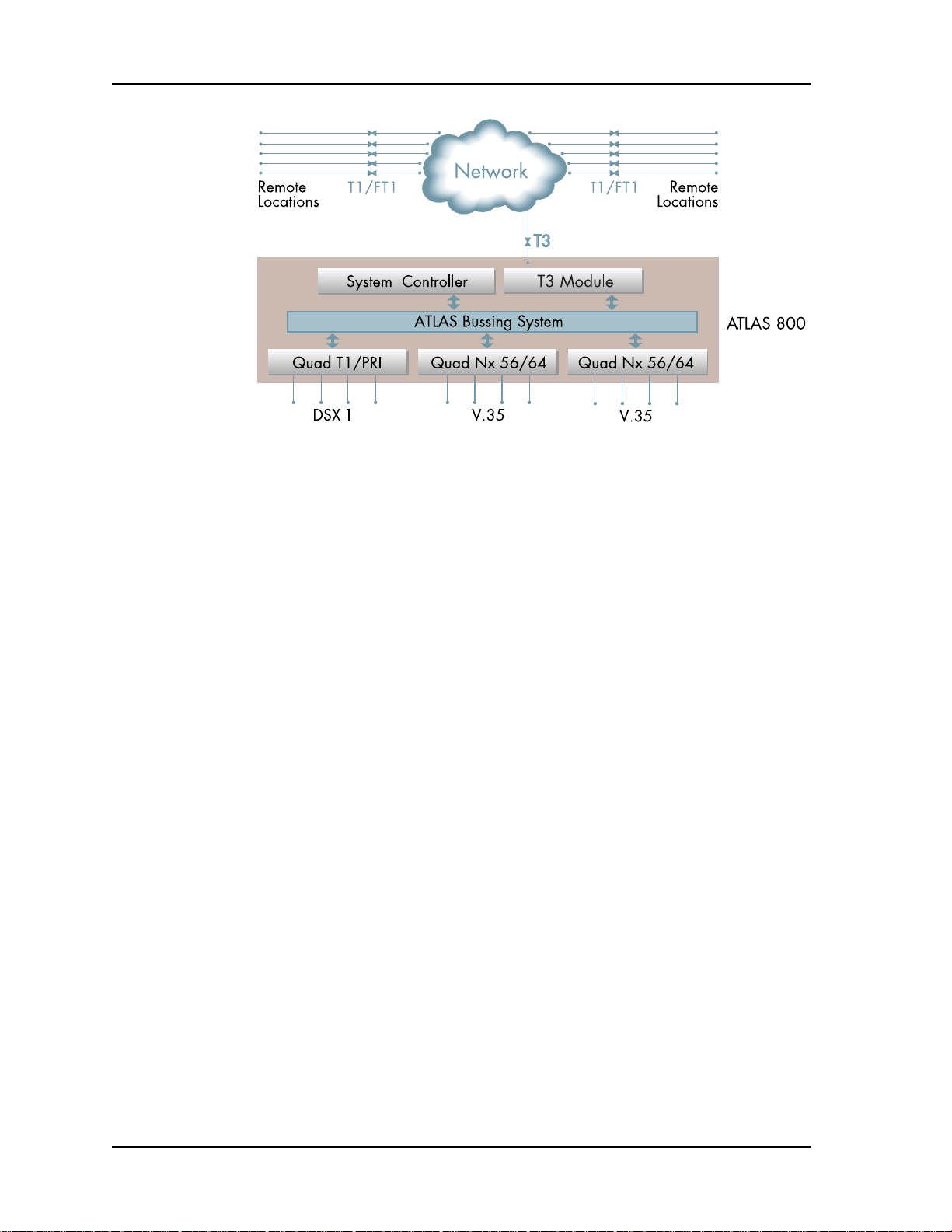
Chapter 1. Introduction
Figure 1-1. T1 Bandwidth Management Application
FUNCTIONAL DESCRIPTION
Features
The T3 Module can be installed in any available option slot in the ATLAS chassis.
The status of the module itself, as well as the circuits to which it interfaces, can be
viewed from the ATLAS front panel. Additional status information is available
via the terminal menu (accessible through either a VT-100 terminal connected to
the ATLAS 800 Base Unit’s control port or through a Telnet session established
through the Base Unit’s Ethernet port). The T3 Module can be configured and
application software can be downloaded using the terminal menu.
• Channelized T3 network interface
• Optional second T3 interface for drop and insert applications
• Cross-connect, drop and insert to the DS0 level (3/1/0 DCAS)
• Extensive performance monitoring of the DS3 or individual T1 circuits
• Software configurable line build-out
• T3 maintenance data link support
• Hot swappable
• 5-year warranty
1-2 T3 Module User Manual 61200223L1-1
Page 13

T3 Module Specifications
Each port of the T3 Module conforms to the following specifications:
Chapter 1. Introduction
Line rate
Capacity
Line Codes
Framing
Te s t s
Connectors
Terminating
Impedance
PHYSICAL DESCRIPTION
The T3 Module plugs into any available option slot in the rear of the ATLAS 800
(see Figure 1-2).
44.736 Mbps, + 895 bps
T3: 28 T1s; 672 DS0s
B3ZS
M13 or C-bit parity
Power-up self test, line loopback, port loopback
BNC female-1 receive, 1 transmit (two additional for D/I)
75 ohms + 5%, unbalanced
Figure 1-2. T3 Module
The T3 Module has a label over each pair of BNC connectors referring to the port
on the card. Each port has a pair of BNC connectors for the T3 circuit interface.
The ports are marked to indicate input and output for the T3 receive and transmit
cables.
61200223L1-1 T3 Module User Manual 1-3
Page 14

Chapter 1. Introduction
1-4 T3 Module User Manual 61200223L1-1
Page 15

Chapter 2 Installation
UNPACK AND INSPECT
Carefully inspect the T3 Module for any shipping damages. If damage is suspected, file a claim immediately with the carrier and then contact ADTRAN Technical Support (see the last page of this manual for pertinent information). If
possible, keep the original shipping container for returning the T3 Module for
repair or for verification of damage during shipment.
Contents of ADTRAN Shipment
The following items are included in the ADTRAN shipment:
• T3 Module
• T3 Module User Manual (to be inserted into the ATLAS 800 User Manual)
• Two six-foot long BNC-BNC (male) cables
INSTALLING THE T3 MODULE
Figure 2-1 represents the action required for proper placement of the T3 Module,
as described here:
1. Remove the option slot cover plate from the ATLAS 800
2. Slide the T3 Module into the option slot until the module is firmly positioned
against the front of the chassis.
3. Fasten the thumbscrews at both edges of the T3 Module.
Figure 2-1. Installing the T3 Module
61200223L1-1 T3 Module User Manual 2-1
rear panel.
Page 16

Chapter 2. Installation
WIRING
Each port of the T3 Module provides a pair of BNC connectors for connecting to
the T3 circuit. Table 2-1 describes the network connection.
Table 2-1. Network Connection
Name Description
RX IN Receive data from the network
TX OUT Transmit data towards the network
POWER UP AND INITIALIZATION
The T3 Module automatically executes a self-test when it powers up. Any previously configured setting for the T3 Module is automatically restored upon power
up. If the T3 Module fails one or more of the self-tests executed during power up,
an error message is displayed on the LCD.
WARRANTY AND CUSTOMER SERVICE
ADTRAN will replace or repair this product within five years from the date of
shipment if the product does not meet its published specification, or if it fails
while in service. For detailed warranty, repair, and return information, refer to the
ADTRAN Equipment Warranty and Repair and Return Policy Procedure (see the
last page of this manual for pertinent information).
A return material authorization (RMA) is required prior to returning equipment
to ADTRAN.
For service, RMA requests, or more information, see the last page of this manual
for the toll-free contact number.
2-2 T3 Module User Manual 61200223L1-1
Page 17

Chapter 3 Operation
OVERVIEW
The ATLAS System Controller automatically detects the presence of the T3 Module when it is installed in the system. You can configure and control the T3 Module from several sources. Table 3-1 shows the various sources, their purpose, and
their access. The ATLAS 800 User Manual provides detailed instructions on oper-
ating each of these supported management approaches. The remainder of this
chapter describes the menu items available for managing the T3 Module using the
terminal menu.
Table 3-1. Management Approaches
Source Purpose Access
ATLAS Front Panel For minimal configuration and
status support
Terminal Menu For detailed configuration,
status, and diagnostics
Simple Network
Management
Protocol (SNMP)
For reporting alarm conditions
and system status
ATLAS 800 Base Unit chassis
VT-100 terminal
ATLAS 800 Base Unit control port
Telnet session
ATLAS 800 Base Unit Ethernet port
T-Watch Pro
You must have the appropriate password level to edit items using the terminal menu. (See the section Access Passwords in the ATLAS User Manual
for detailed information on working with passwords.)
Security level 0 users can view and edit every available field. Security level
5 users can view any field, but they cannot edit.
TERMINAL MENU STRUCTURE
The ATLAS 800 uses hierarchical menus to access all of its features. The top-most
menu level leads to submenus which are grouped by functionality. All menu
items display in the terminal window. You can use the Modules terminal menu to
configure and control the T3 Module (see Figure 3-1 on page 3-2).
61200223L1-1 T3 Module User Manual 3-1
Page 18

Chapter 3. Operation
MENU ACCESS
Figure 3-1. Modules Menu
To access the Modules menu and submenus, use the keyboard arrow keys to
scroll to the appropriate row and column; then press ENTER on the keyboard.
For example, to view the Menu submenus for T3-2 (as shown in Figure 3-1), use
the keyboard arrow keys to scroll down to Modules, right to T3-2, and right again
to the Menu column; then press ENTER.
Refer to the Atlas 800 User Manual for detailed instruction on navigating
through the terminal menu.
T3 MODULE MENU DESCRIPTIONS
The following paragraphs (Slt (slot), Type, Menu, Alarm, Test, State, Status, and
Rev (revision)) describe the Modules menus and submenus. Unless a write security-level is given, all menus and submenus are read-only.
Slt (slot)
Read security: 5
Displays the number of available option slots in the ATLAS 800 chassis. Slot 0
refers to the ATLAS 800 Base Unit.
Type
Write security: 3; Read security: 5
Displays the type of module currently installed in the slot or the module type you
plan to install in the slot. For instance, if a T3 Module is installed, the Ty pe field
automatically defaults to T3-1 or T3-2. You can use this field to preconfigure a system before installing modules; simply specify the module that you want to install
into each slot.
If a module is installed, Type automatically displays the name of the installed module, and it cannot be set to any other option.
3-2 T3 Module User Manual 61200223L1-1
Page 19

Chapter 3. Operation
Menu
Displays additional status and configuration menus for the selected module. (See
“T3 Module Modules Submenus” on page 3-4 for detailed information on each
submenu.)
Alarm
Read security: 5
Displays whether there is an alarm condition on the T3 Module.
Test
Read security: 5
Displays whether the T3 Module is executing a test.
State
Write security: 3; Read security: 5
Displays whether the module is online or offline. Even though a module is physically installed, it must be marked Online for it to be considered an available
resource. This field allows an installed module to be marked Offline, which may
be useful in system troubleshooting. If you choose Offline, the module will not be
in alarm condition, but will display Offline.
A module must be in the Online state in order for ATLAS to use the module
for any data bandwidth.
Status
Read security: 5
Displays status information on the T3 Module. Table 3-2 on page 3-3 describes status messages that may display.
Rev (Hardware Revision)
Read security: 5
Displays the hardware revision of the T3 Module.
Table 3-2. Status Messages
Message Meaning
Online The module is enabled and is responding to the system controller’s status
polls. This is the normal response of the system.
No
Response
Empty The system controller has not detected the presence of a module in the slot,
Offline The module is installed, but has been taken Offline by a user. The module is
The module is enabled, but is not responding to the system controller’s
status polls. This response indicates either a problem in the system or that
the module is not installed.
nor has a module been manually enabled for this option slot.
still responding to controller polls.
Offline/
No
Response
61200223L1-1 T3 Module User Manual 3-3
The module is installed, but has been taken Offline by a user. The module is
not responding to controller polls.
Page 20

Chapter 3. Operation
T3 MODULE MODULES SUBMENUS
Figure 3-2 shows the Menu submenu options for the T3-1 and T3-2 Modules. The
following sections describe these options.
Figure 3-2. T3-2 Menus Screen
T3-2 Menus
Read security: 5
Displays module configuration and status information.
T3 Info
Read security: 5
Indicates the status of the module (see Figure 3-3).
Figure 3-3. T3 Info Screen
3-4 T3 Module User Manual 61200223L1-1
Page 21

Chapter 3. Operation
Part Num Displays the part number of the module (read only).
Serial Number Displays the serial number of the module (read only).
Board Rev Displays the PCB revision (read only).
T1s Dropped
(T3-2 Module only)
MUX Configuration
Displays the number of the T1s incoming on the primary T3
interface that are terminated or dropped in this unit.
(T3-2 Module only)
Write security: 3; Read security: 5
Allows users to define which T1s should be dropped or passed on. T1s are
dropped in pairs. (See Figure 3-4.)
Figure 3-4. MUX Configuration Screen
T1 Disposition This field has 28 letters which, from left to right, represent
T1s 1 through 28 being delivered to the ATLAS 800
through the primary T3 interface.
D Dropped (available to be terminated in the ATLAS 800)
P Pass through (passed out through the secondary T3
interface)
T1s Dropped This field shows the number of T1s from the T3-2 module
available to terminate in the ATLAS 800.
T1s Passed Thru This field shows the number of T1s from the T3 module that
are passed out the secondary T3 interface to other
equipment.
T1 Pair 1-2
through
T1Pair 27-28
These fields indicate which pairs of T1s of the T3
bandwidth are selected to be dropped or passed through.
61200223L1-1 T3 Module User Manual 3-5
Page 22

Chapter 3. Operation
T3 Alarm Status
Read security: 5
Indicates the current alarm status of the T3 interface (see Figure 3-5).
Figure 3-5. T3 Alarm Status Screen
Prt
Indicates the port number.
Alarms
Lists the following alarms:
FE Alarms
LOS (Loss of Signal) Detects no signal at T3 port interface.
RED (Loss of Frame or
BLUE (Alarm Indication Signal
IDLE (Idle) Receiving idle signal in T3 payload from
YELLOW (Remote Alarm Indication
CBIT (C-bit) Indicates reception of C-bit parity framing.
(Far End Alarms)
RED Alarm)
or BLUE Alarm)
or Yellow Alarm)
Received T3 cannot be framesynchronized. Out of frame for 2.5
seconds.
Receiving alarm indication signal in T3
payload from far end equipment.
far-end equipment.
Receiving RAI signal. Far-end equipment is
in RED alarm.
Displays received alarms over the FEAC channel for C-bit parity applications.
T3 Performance - Current, 15min, 24Hr
Read security: 5
Accumulates various types of T3 performance statistics for current, 15-minute
interval, and 24-hour interval categories. Performance measures comply with
ANSI T1.231-1993 for DS3 interfaces (see Figure 3-6).
3-6 T3 Module User Manual 61200223L1-1
Page 23

Figure 3-6. T3 Performance (Current) Screen
PRT
Indicates port number.
Chapter 3. Operation
CLR[+]
Write security: 3
Clears all of the counts to 0 for the selected port when you scroll to this field
and press RETURN.
ES_L
(Errored Seconds - Line)
SES_L
(Severely Errored Seconds Line)
LOSS_L
(Loss of Signal Second-Line)
CV_P
(Code Violation - Path
ES_P
(Errored Second - Path)
SAS_P
(SEF/AIS Second)
Count of seconds containing excessive zeros,
LOS, or BPVS, not due to line code substitutions.
Count of seconds containing excessive zeros,
LOS, or BPVS, not due to line code substitutions
above a predetermined threshold.
Count of seconds of LOS condition.
For the M13 application, an accumulation of
P-bit parity errors. For the C-bit parity
application, an accumulation of CP-bit parity
errors.
An accumulation of seconds during which any
one of the following conditions exist: parity
errors, severely errored frame, or AIS signal
received.
An accumulation of seconds during which
severely errored frames or AIS signal is
received.
SES_P
(Severely Errored Seconds Path)
UAS_P
(Unavailable Seconds - Path)
61200223L1-1 T3 Module User Manual 3-7
An accumulation of seconds during which parity
errors, severely errored frames, or AIS signal is
received.
An accumulation of one-second intervals during
which the DS3 path is unavailable; i.e., 10
contiguous SES_Ps.
Page 24

Chapter 3. Operation
T3 Configuration
Write security: 3; Read security: 5
Includes all of the configurable parameters pertaining to the T3 interface in
this menu chain (see Figure 3-7).
Figure 3-7. T3 Configuration Screen
Prt Port number of the T3 module.
Port
Name
Frame The selected T3 framing format: M13 or C-bit.
Tx Clock Selects source of T3 transmit clock.
LBO Line build-out setting for T3 transmitter.
Name assigned to the associated T3 port.
Recovered - derives transmit T3 timing from the receive T3.
Internal - derives transmit T3 timing from the internal +
crystal source.
Short - 0 to 100 feet of cable.
Long - 100 to 450 feet of cable.
20 PPM
3-8 T3 Module User Manual 61200223L1-1
Page 25

T3 Test
Write security: 3; Read security: 5
Executes loops and indicates test status (see Figure 3-8).
Figure 3-8. T3 Test Screen
Chapter 3. Operation
Prt
Loopback
Remote
LB
Remote
Status
Indicates the T3 module port under test.
This field indicates the present loopback selected.
None - No loopback in effect
Line - T3 line loopback active
Indicates if loopbacks initiated from remote sources are in effect and
may be used to execute remote loopbacks on the far-end T3.
None - No remote loopbacks are activated.
DS3 Line - Remote DS3 line loopback is activated.
DS1 #1... DS1 #28 - Remote individual T1 line loopback is acti-
vated.
DS1 All - Remote T1 line loopbacks for all 28 T1s is activated.
Indicates progress of remote loopbacks.
Line Loopback Active - Remote line loopback is active.
No Loops Active - Remote line loopbacks are inactive.
61200223L1-1 T3 Module User Manual 3-9
Page 26

Chapter 3. Operation
T1 Alarm Status
Read security: 5
Indicates T1 alarm status (see Figure 3-9).
Figure 3-9. T1 Alarm Status Screen
Prt Specifies port number.
Alarms:
Red Not able to frame data on the port; also, referred to as
OOF.
Yellow Port receiving remote alarm indication (RAI).
Blue Receiving unframed 1s from the port; also called AIS.
D-Chan D channel alarm is only meaningful if T1 is defined as a
PRI. (Requires using an HDLC controller on another
card.)
3-10 T3 Module User Manual 61200223L1-1
Page 27

Chapter 3. Operation
T1 DS0 Status
Read security: 5
Indicates usage on a DS0 basis for each port (see Figure 3-10).
Figure 3-10. T1 DS0 Status Screen
- Unallocated DS0
Inactive DS0
•
+ Signalling mismatch DS0
A Active call on this DS0
D Active D channel DS0
M Maintenance DS0
N Dedicated DS0
O Off hook detected
R Ringing detected
W Waiting for dial tone
T1 Sig Status
Read security: 5
Indicates signaling of all 24 DS0s. The A/B bits for Rx (receive) and Tx (transmit) DS0s are shown for each port. Dashes display for those DS0s where
robbed-bit signaling is not being transferred by the ATLAS 800 (see Figure 3-
11).
61200223L1-1 T3 Module User Manual 3-11
Page 28

Chapter 3. Operation
Figure 3-11. T1 Signal Status
T1 Performance: Current, 15min, 24Hr
Write security: 4; Read security: 5
Provides status on key performance measures as specified in ANSI T1.403
and AT&T TR54016 for each of the T1 ports for each performance field (either
current, 15-minute total, or 24-hour total). Excepting CLR, these fields are all
read-only (see Figure 3-12).
Figure 3-12. T1 Performance (Current) Screen
3-12 T3 Module User Manual 61200223L1-1
Page 29

Chapter 3. Operation
Prt
CLR
ES Errored Seconds. An ES is a second with one or more error events
BES
SES
SEFS
LOFC
CSS
UAS
Displays the port number.
Clears performance information for the selected port.
OR one or more Out Of Frame events OR one or more Controlled
Slips.
Bursty Errored Seconds. A BES is a second with more than one, but
less than 320 error events.
Severely Errored Seconds. An SES is a second with 320 or more
error events OR one or more Out Of Frame events.
Severely Errored Frame Seconds.
Loss of Frame Count.
Controlled Slip Seconds.
Unavailable Seconds.
T1 Configuration
Various security levels apply for these configurable parameters (see also Figure 3-13).
Figure 3-13. T1 Configuration Screen
61200223L1-1 T3 Module User Manual 3-13
Page 30

Chapter 3. Operation
Prt
Port Name
Frame
Tx Yellow
(Auto Tx
Ye ll ow Al a rm )
Tx PRMs
(Transmit PRMs)
LB Accept
(Loopback
Accept)
Read security: 5
Displays the port number.
Write security: 3; Read security: 5
Allows users to identify each port on the T3 Module with a
unique alpha-numeric name. Names can be up to 16
characters long.
Write security: 2; Read security: 5
Set this field to match the frame format of the circuit to which
it is connected, available from the network supplier. Choose
either D4 or ESF.
Write security: 3; Read security: 5
Controls the transmitting of yellow alarms. Choose either On
or Off.
Write security: 3; Read security: 5
Controls the sending of performance report messaging
(PRM) data on the facility data link (FDL). The PRM data
continues to be collected even if XMIT PRM is turned off
(possible only with ESF format). Choose either On or Off.
Write security: 3; Read security: 5
Sets unit to accept or reject the in-band loop up and loop
down codes as defined in ANSI T1.403. This is a line
loopback. Choose either Accept or Ignore.
T1 Test
Write security: 4; Read security: 5
These options initiate different types of tests and display test results (see Figure 3-14).
Figure 3-14. T1 Test Screen
These test commands temporarily disrupt service.
3-14 T3 Module User Manual 61200223L1-1
Page 31

Chapter 3. Operation
Prt
Loc LB
(Local Loopback)
Remote LB
(Remote
Loopback)
Pattern
QRSS/RLB
Results
(Test Pattern
Results)
Read security: 5
Displays the port number.
Write security: 4; Read security: 5
Causes loopback on near-end port. Includes the following
options:
Line — Loopback without regenerating framing
Payld — Payload loopback - framing and clocking are
regenerated. (See Figure 3-15 on page 3-15.)
Write security: 4; Read security: 5
Sends loopback code to remote CSU. Includes the
following options:
ANSI FDL Line (Requires ESF mode)
•
•ANSI FDL Pyld (Requires ESF mode)
•AT&T Inband line
Write security: 4; Read security: 5
Test pattern to be transmitted out the port. Includes the
following options:
All ones — framed ones
All zeros — framed zeros
QRSS — pseudorandom pattern with suppression of
excess zeros.
Write security: 4; Read security: 5
Indicates sync and errors of received data pattern.
Clr
(Clear Test Pattern
Results)
Inj
(Inject Test Pattern
Error)
T1 Payload Loopback
T1 Framer #1
.
.
.
.
.
.
.
.
.
.
T1 Framer
#28
Figure 3-15. Network Loopback Test
Write security: 4; Read security: 5
Clears error counters on test pattern results menu.
Write security: 4; Read security: 5
Injects errors into transmitted test pattern.
T3 Module
T1 Line
Loopback
.
.
M13
Mux
T3 Line
Loopback
T3
Front
End
T3 Line
61200223L1-1 T3 Module User Manual 3-15
Page 32

Chapter 3. Operation
ATLAS 800 FEATURES USED WITH T3-1 OR T3-2 MODULES
In addition to the T3 Module menu items, two other ATLAS 800 menu items may
be operated in conjunction with the T3 Modules. These items are Factory Restore
and Run Self-Test.
Factory Restore
Factory Restore, a submenu of the ATLAS 800 front panel main menu item Utilities (UTIL), restores the factory-installed default setting for all T3 Module parameters. When Factory Restore displays, place the cursor on it and press ENTER.
The unit is restored to preset factory defaults and returns to the main ATLAS 800
menu.
Run Self-Test
Run Self-Test, a submenu of the ATLAS 800 main menu item Test, executes both
the T3 Module internal test and the ATLAS 800 internal test. For additional information on Self-Test see the ATLAS 800 User Manual. When Run Self-Test displays,
place the cursor on it and press ENTER to execute the test. The results of the selftest are displayed in the LCD.
Mapping
DS0s are used as defined in the Dedicated Map or in the Dial Plan for switched
applications. (See the ATLAS 800 User Manual for a description.)
3-16 T3 Module User Manual 61200223L1-1
Page 33

Appendix A Dial Plan Interface Configuration
INTERFACE CONFIGURATION
The interface configuration option for the Dial Plan menu sets configuration
parameters for the end point. These parameters vary by the type of port selected.
The following section describes the configuration options available for the T3-1
and T3-2 Modules. The Dial Plan menus are only accessible when using terminal
mode. To access these options, select Dial Plan from the top level menu (see Figure A-1).
The Write security level for all Dial Plan options is 3.
Figure A-1. Dial Plan Menus
T3 MODULE INTERFACE CONFIGURATION
This section describes the network termination and user termination configuration settings for the T3-1 and T3-2 Modules when using the Dial Plan menus.
These menus represent the T3 Module as having 28 T1 ports to configure.
61200223L1-1 T3 Module User Manual A-1
Page 34

Appendix A. Dial Plan Interface Configuration
T3 Module (Network Termination/RBS)
When you are working in the Network Termination section of the Dial Plan menu,
Slot is defined as a T3-1 or T3-2 Module, and Sig is set to RBS, the following inter-
face configuration options are available:
First DS0
Write security: 2; Read security: 5
Defines to the ATLAS 800 the DS0s used for this end point. These are the DS0s
which the ATLAS 800 uses to send and receive calls to and from the network
(PSTN). The outgoing calls which are allowed or restricted over these DS0s
are set by the Outgoing Call Accept and Reject Numbers discussed earlier.
Number of DS0s
Write security: 3; Read security: 5
Specifies the number of DS0s already defined for this end point. This field is
read-only.
DS0s Available
Read security: 5
Indicates which DS0s of the T1 have been defined in this switched end point
(indicated by "!"), in another switched end point (indicated by "s"), or in a
Dedicated Map (indicated by "n"). The following symbols may display in this
field:
digits
0-9
*
!
s
S
n
N
This DS0 is available. The digit that displays in this field represents
the last digit of the DS0 number.
This port is requesting this DS0 for this connection, but the DS0 is
not yet activated.
This DS0 is used by this end point.
This DS0 is used elsewhere in the switched dial plan.
This DS0 is in the switched dial plan and conflicts with this end
point.
This DS0 is used in one or more dedicated maps.
This DS0 is in one or more dedicated maps and conflicts with this
end point.
Trunk Type (Voice/SW56)
Write security:3; Read security:5
Use this field if the incoming service on this trunk is Switched 56 digital
instead of standard voice.
Signaling Method
Write security: 3; Read security: 5
Defines to the ATLAS 800 the type of signaling to be used across this trunk.
The signaling selected needs to match the signaling being provided by the
network (PSTN). The following choices are available:
• E&M Immediate
•E&M Wink
•Loop Start
• Ground Start
A-2 T3 Module User Manual 61200223L1-1
Page 35

Appendix A. Dial Plan Interface Configuration
Direct Inward Dialing (DID)
Write security: 3; Read security: 5
Defines to the ATLAS 800 whether DID is being used by the network. If DID
is Enabled, then you must define the following information:
DID Digits Transferred
Write security: 3; Read security: 5
Defines the number of digits sent to the ATLAS 800 from the network if
DID is used.
DID Prefix
Write security: 3; Read security: 5
Defines to the ATLAS 800 the prefix digits which are not received as a
part of the DID number. ATLAS uses the combination of prefix and DID
number to determine the user end point that should receive the incoming
call.
This option displays only if direct inward dialing (DID) is set to Enabled.
If DID is Disabled, then you must define the trunk number.
Trunk Number
Write security: 3; Read security: 5
When the network connection does not provide DID digits, the ATLAS 800
must be given a number to use to determine which user end point should
receive the incoming call. This option displays only when direct inward dialing is set to Disabled.
The trunk number must be specific (i.e., no “wild cards”).
For example, if an incoming DS0 (trunk) is meant to connect to an end point
with the Accept number of 963-8615, the trunk number would be set to 963-
8615.
T3 Module (User Termination/RBS)
When you are working in the user termination section of the Dial Plan menu,
when the Slot is defined as a T3-1 or T3-2 module, and when Sig is set to RBS, the
following configuration options are available:
First DS0/Number of DS0s
Write security: 3; Read security: 5
Defines to the ATLAS 800 the DS0s which will be used for this end point. The
ATLAS 800 uses these DS0s to send and receive calls to and from user equipment (PBX). The incoming calls which will be accepted and the outgoing calls
which will be restricted over these DS0s are set by the Incoming Call Accept
and Outgoing Call Reject Numbers discussed earlier.
61200223L1-1 T3 Module User Manual A-3
Page 36

Appendix A. Dial Plan Interface Configuration
DS0s Available
Read security: 5
Indicates which DS0s of the T1 have been defined in this switched end point
(indicated by “! “), in another switched end point (indicated by “s”), or in a
dedicated map (indicated by “n”).
digits
0-9
*
!
s
S
n
N
This DS0 is available. The digit that displays in this field represents
the last digit of the DS0 number.
This port is requesting this DS0 for this connection, but the DS0 is
not yet activated.
This DS0 is used by this end point.
This DS0 is used elsewhere in the switched dial plan.
This DS0 is in the switched dial plan and conflicts with this end
point.
This DS0 is used in one or more dedicated maps.
This DS0 is in one or more dedicated maps and conflicts with this
end point.
Signaling Method
Write security: 3; Read security: 5
Defines to ATLAS the type of signaling to be used across this trunk. The
selected signaling must match that being used by the user equipment (PBX).
The choices include the following:
• E&M Immediate
•E&M Wink
•Loop Start
• Ground Start
ATLAS converts signaling types between network and user terminations.
Direct Inward Dialing (DID)
Defines to the ATLAS 800 whether DID is used by the user equipment. If DID
is Enabled, then the following information must be defined:
DID Digits Transferred
Defines the number of digits the ATLAS 800 sends on to the user equipment. This field only displays if direct inward dialing is set to Enabled.
A-4 T3 Module User Manual 61200223L1-1
Page 37

Appendix A. Dial Plan Interface Configuration
Caller ID Number
Defines the number the ATLAS 800 uses to provide caller ID to the network for outgoing calls sent through this end point. This option only displays if direct inward dialing is set to Disabled. This item is optional.
The Caller ID number must be specific (i.e., no “wild cards”).
61200223L1-1 T3 Module User Manual A-5
Page 38

Appendix A. Dial Plan Interface Configuration
A-6 T3 Module User Manual 61200223L1-1
Page 39

Index
A
alarm
BLUE 3-6
CBIT 3-6
IDLE 3-6
LOS 3-6
RED 3-6
YELLOW 3-6
yellow auto TX 3-14
alarms 3-3
applications
typical 1-1
ATLAS 800 1-1
ATLAS 800 features 3-16
auto TX yellow alarm 3-14
B
bandwidth management application 1-1, 1-2
C
capacity 1-3
clock source tests 1-3
configuration 3-13
end point A-1
Quad T1/PRI interface A-1
connectors 1-3
customer service 2-2
D
default settings 3-16
description
functional 1-2
physical 1-3
disrupted service 3-14
DS0s, number of A-2
E
end point configuration A-1
F
factory restore 3-16
far end alarms 3-6
FE alarms
BLUE 3-6
CBIT 3-6
IDLE 3-6
LOS 3-6
RED 3-6
YELLOW 3-6
features 1-2
ATLAS 800 3-16
first DS0 number A-3
framing options 1-3
functional description 1-2
H
hardware revision 3-3
I
initialization 2-2
Installation 2-1
Installing 2-1
installing the module 2-1
interface
configuration
Quad T1/PRI A-1
introduction 1-1
L
line codes 1-3
line rate 1-3
local loopback 3-15
loopback
61200223L1 T3 Module User Manual Index-1
Page 40

Index
local 3-15
loopback accept 3-14
LOS 3-6
loss of signal 3-6
M
mapping DS0s 3-16
menu
description 3-2
modules 3-2
modules menu 3-2
MUX configuration 3-5
T1 disposition 3-5
T1 pair 1-2 through T1pair 27-28 3-5
T1s dropped 3-5
T1s passed thru 3-5
N
N A-2
n A-2
network termination
configuration settings A-1
O
operation 3-1
Overview 3-1
overview 1-1
P
performance current 3-12
physical description 1-3
port
T3 alarm status 3-6
power up 2-2
Q
Quad T1/PRI
interface configuration A-1
R
restore factory settings 3-16
RMA 5
RMA requests 2-2
run self-test 3-16
S
S A-2
s A-2
self-test 3-16
service 2-2
service, disrupted 3-14
shipping contents 2-1
slot 3-2
specifications 1-3
state 3-3
status 3-3
alarm, T3 3-6
DSO 3-11
sig(naling) 3-11
submenus 3-4
MUX configuration 3-5
T1 disposition 3-5
T1 pair 1-2 through T1pair 27-28 3-5
T1s dropped 3-5
T1s passed thru 3-5
T1 alarm status 3-10
alarms 3-10
blue
3-10
red
3-10
yellow
PRT 3-10
T1 configuration 3-13
frame 3-14
LB accept 3-14
port name 3-14
Prt 3-14
Tx PRMs 3-14
Tx yellow 3-14
T1 DSO status 3-11
T1 performance
current, 15min, 24Hr 3-12
BES
3-13
CLR
3-13
CSS
3-13
ES
3-13
LOFC
Prt
SEFS
SES
UAS
T1 sig(naling) status 3-11
T1 test 3-14
Clr (clear) 3-15
inj 3-15
local loopback 3-15
Prt 3-15
QRSS/RLB results 3-15
remote LB 3-15
remote loopback 3-15
T3 alarm status 3-6
alarms 3-6
LOS
FE alarms 3-6
3-13
3-13
3-13
3-13
3-13
3-6
3-10
Index-2 T3 Module User Manual 61200223L1
Page 41

Index
BLUE
CBIT
IDLE
LOS
RED
3-6
3-6
3-6
3-6
3-6
YELLOW
port 3-6
T3 configuration 3-8
frame 3-8
LBO 3-8
long
3-8
short
3-8
port name 3-8
PRT 3-8
Tx clock 3-8
T3 performance
current, 15min, 24Hr 3-6
PRT
3-7
T3 test 3-9
loopback 3-9
none
3-9
PRT 3-9
remote LB 3-9
DS1 #1... DS1 #28
DS1 all
DS3 line
none
3-9
remote status 3-9
line loopback active
no loops active
T3-2 menus 3-4
board revision 3-5
part num 3-5
serial number 3-5
T1s dropped 3-5
T3 info 3-4
T
T1 alarm status 3-10
alarms 3-10
blue 3-10
red 3-10
yellow 3-10
PRT 3-10
T1 configuration 3-13
frame 3-14
LB accept 3-14
port name 3-14
Prt 3-14
Tx PRMs 3-14
Tx yellow 3-14
3-9
3-9
3-6
3-9
3-9
3-9
T1 DSO status 3-11
T1 performance
current, 15min, 24Hr 3-12
BES 3-13
CLR 3-13
CSS 3-13
ES 3-13
LOFC 3-13
Prt 3-13
SEFS 3-13
SES 3-13
UAS 3-13
T1 sig(naling) status 3-11
T1 test 3-14
clear test pattern 3-15
Clr (clear) 3-15
inj 3-15
inject errors 3-15
local loopback 3-15
Prt 3-15
QRSS/RLB results 3-15
remote LB 3-15
remote loopback 3-15
T3 alarm status 3-6
alarms 3-6
FE alarms
BLUE 3-6
CBI 3-6
IDLE 3-6
LOS 3-6
RED 3-6
YELLOW 3-6
port 3-6
T3 configuration 3-8
frame 3-8
LBO 3-8
long 3-8
short 3-8
port name 3-8
PRT 3-8
Tx clock 3-8
T3 Module
direct inward dialing A-3
DS0, first A-2
network termination/RBS A-2
DID A-3
digits transferred
prefix
A-3
DS0s available A-2
first DS0 A-2
number of DS0s A-2
signaling method A-2
trunk type A-2
A-3
61200223L1 T3 Module User Manual Index-3
Page 42

Index
trunk type A-2
user termination/RBS A-3
DID A-4
caller ID number
DID digits transferred
DS0s available A-4
first DS0 number A-3
number of DS0s A-3
signaling method A-4
T3 performance
current, 15min, 24Hr 3-6
PRT 3-7
T3 test 3-9
loopback 3-9
none 3-9
PRT 3-9
remote LB 3-9
DS1 #1... DS1 #28 3-9
DS1 all 3-9
DS3 line 3-9
none 3-9
remote status 3-9
line loopback active 3-9
A-5
A-4
no loops active 3-9
terminating impedance 1-3
test 3-3, 3-14
test pattern 3-15
error inject 3-15
transmit PRMs 3-14
trunk
number A-3
trunk type A-2
type 3-2
U
user
termination configuration settings A-1
W
warranty 2-2
wiring 2-2
Y
yellow alarm
auto TX 3-14
Index-4 T3 Module User Manual 61200223L1
Page 43

Product Support Information
Presales Inquiries and Applications Support
Please contact your local distributor, ADTRAN Applications Engineering, or ADTRAN Sales:
Applications Engineering (800) 615-1176
Sales (800) 827-0807
Post-Sale Support
Please contact your local distributor first. If your local distributor cannot help, please contact
ADTRAN Technical Support and have the unit serial number available.
Technical Support (888) 4ADTRAN
Repair and Return
If ADTRAN Technical Support determines that a repair is needed, Technical Support will
coordinate with the Customer and Product Service (CAPS) department to issue an RMA
number. For information regarding equipment currently in house or possible fees associated
with repair, contact CAPS directly at the following number:
CAPS Department (256) 963-8722
Identify the RMA number clearly on the package (below address), and return to the following
address:
ADTRAN Customer and Product Service
6767 Old Madison Pike
Progress Center
Building #6 Suite 690
Huntsville, Alabama 35807
RMA # _____________
Page 44

 Loading...