

Page 1
High Capacity T200/T400 Cabinet
Installation and Maintenance
CONTENTS
1. GENERAL ..................................................................... 1
2. INSTALLATION............................................................ 4
3. TESTING ..................................................................... 15
4. MAINTENANCE......................................................... 18
5. WARRANTY AND CUSTOMER SERVICE .............. 20
FIGURES
Figure 1. High-Capacity T200/T400 Cabinet
(Pad Mount Model) ........................................... 1
Figure 2. Cabinet Assembly, Rear View............................ 3
Figure 3. Top View Cutaway With Installation
Measurements.................................................... 3
Figure 4. Pad Mount Dimensions ...................................... 5
Figure 5. Lifting Detail Assembly..................................... 5
Figure 6. Pad Mounting Bracket Installation .................... 6
Figure 7. Pole Mount Dimensions..................................... 6
Figure 8. Mounting Bracket Assembly.............................. 7
Figure 9. Bottom Support Bracket Assembly.................... 8
Figure 10. Guide for Pole Mounting .................................. 8
Figure 11. Sealing Grommet Assembly .............................. 9
Figure 12. Shield Connector Assembly............................ 10
Figure 13. Primary & Secondary Fan Boards .................. 15
Figure 14. Surge Arrestor Board....................................... 18
Figure 15. Surge Arrestor Gas Tube Replacement .......... 18
Figure 16. Door Switch .................................................... 20
TABLES
Table 1. T200/T400 Cabinet Basic Features ..................... 2
Table 2. Pad Mounting Hardware ..................................... 5
Table 3. Pole Mount Hardware ......................................... 7
Table 4. Seal Grommet Kit................................................ 9
Table 5A.Splice Module 1 ................................................ 12
Table 5B.Splice Module 2 ................................................ 12
Table 6A.Circuit Technology Configuration
Chart (Part 1) ..................................................... 13
Table 6B.Circuit Technology Configuration
Chart (Part 2) ..................................................... 14
Table 7. Replacement Item Part Numbers....................... 18
Table 8. Customer & Circuit Information ....................... 21
1. GENERAL
This practice provides installation and maintenance
procedures for the ADTRAN High-Capacity
Section 61150090L1-5
Issue 1, April 1999
List 1: CLEI CODE # T1MJ4U0MRA
List 2: CLEI CODE # T1MJ5U0MRA
List 3: CLEI CODE # T1MJ4V0MRA
List 4: CLEI CODE # T1MJ5V0MRA
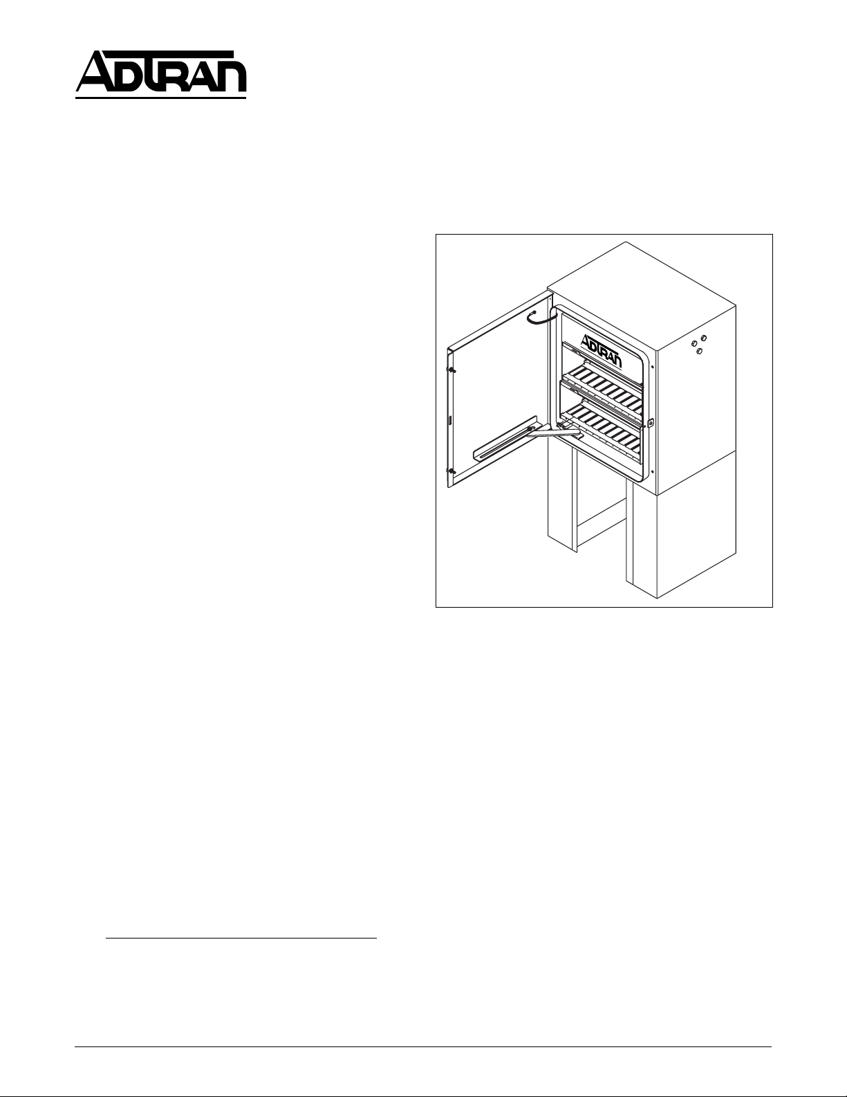
Figure 1. High-Capacity T200/T400 Cabinet
(Pad Mount Model)
T200/T400 Cabinet. Figure 1 is an illustration of the
unit. Four models are available.
The part numbers and basic features of each cabinet
model are provided in Table 1. The cabinet is a highcapacity T200/T400 enclosure which supports the
demand for numerous circuits spread over small areas.
Revision History
This is the first issue of this document. Future
revisions will be described in this paragraph.
Practice Review
This Practice contains important pre-installation
information. Craft personnel should review Sections 1
and 2 of this Practice as part of installation planning.
Description
The ADTRAN T200/T400 High Capacity Cabinet is
an outdoor, above-ground enclosure. Up to 24
61150090L1-5A Section 61150090L1-5A, Issue 1 1
Trademarks: Any brand names and product names included in this document are
trademarks, registered trademarks, or trade names of their respective holders.
Page 2

ADTRAN Line Powered T200 or T400 Circuit Packs
can be installed per cabinet. The cabinet system is prewired with surge arrestor boards to reduce installation
and turn-up time. Wiring consists of either pre-wired
cable stubs or pre-wired internal splice module
connections depending on the model.
The cabinet body is constructed of aluminum with a
powder coated gray finish. Earth ground connects to
the ground lug on the bottom of the cabinet. The nonvented enclosure protects the internal electronic
circuitry from the surrounding environmental
conditions.
For the pad mount model, the cabinet sits on two
bolt-on mounting brackets. The brackets are in-turn
bolted to the craft designated pad. The front and back
security access panels are then bolted to the brackets
to provide a secure enclosure for the wire runs exiting
the bottom of the cabinet.
All models incorporate tamper resistant access with
lockable front and rear cabinet doors, replaceable
surge arrestor gas tubes, and replaceable fan modules.
Features
The T200/T400 High Capacity Cabinet includes the
following features and components:
• Two 19 inch T200/T400 chassis with 24 slots
(2x12) for line powered T400 or T200 Circuit
Packs.
• Line powered internal cooling fans.
• Pre-wired 50 foot cable stubs, or internal splice
module connections, depending on the model.
• Pre-installed splicing modules on cable stub
ends or wiring harness for fast, simple
connections at the customer’s site or splice case.
• Surge arrestors are provided for each slot with
replaceable gas tubes.
• Gas tube extraction pliers.
• Moisture absorbing desiccant.
• Spare cable hole entrance with removable seal.
• Mounting template for craft planning.
Cabinet Access
The front and rear cabinet doors and support bracket
access panels include tamper resistant security
fasteners. The cabinet doors allow for a customer
supplied lock for added security. The front door
provides access to insert and remove the circuit packs
and desiccant bags. The rear door provides access to
the chassis backplane, cable and wire connections, fan
boards, and surge arrestor boards. All cable
penetrations are through the bottom panel.
When opened, the front and rear door switches
provide intrusion detection at the Central Office FPU
(Fan Power Unit). The door switch can then be
manually positioned to disable intrusion detection.
The door switch automatically resets when the door
closes. Retainers hold the door open until they are
manually released. Front and rear door features are
identical. Refer to Figure 2 for cabinet details, rear
view.
Mounting
The Cabinet is pad or pole mountable depending on
the model. The cabinet is for above ground use only.
The pad mounted model includes two interchangeable
boxlike brackets that raise the cabinet 18 inches above
the pad to allow easier access, provide additional
clearance for manipulating cables, and protection from
a high water condition. Pole mounting is
recommended where water conditions could reach a
pad mounted cabinet.
Mounting Template
The pad mounting footprint dimensions are provided
as a full size template on the unit’s packaging, and
complete installation measurements are shown in
Figure 3.
Table 1. T200/T400 Cabinet Basic Features
rebmuNtPIELCserutaeF
1L0900511ARM0U4JM1T
2L0900511ARM0U5JM1T
3L0900511ARM0V4JM1T
4L0900511ARM0V5JM1T
2 Section 61150090L1-5A, Issue 1 61150090L1-5A
.elbacdeilppusremotsucotnoitcennocrofseludom
.elbacdeilppusremotsucotnoitcennocrofseludom
.sbutselbaclanretxehtiwdetnuomdaP.skcaptiucric004T/002Tderewopenil42sesuoH
ecilpslanretnihtiwdetnuomdaP.skcaptiucric004T/002Tderewopenil42sesuoH
ecilpslanretnihtiwdetnuomeloP.skcaptiucric004T/002Tderewopenil42sesuoH
.sbutselbaclanretxehtiwdetnuomeloP.skcaptiucric004T/002Tderewopenil42sesuoH
Page 3
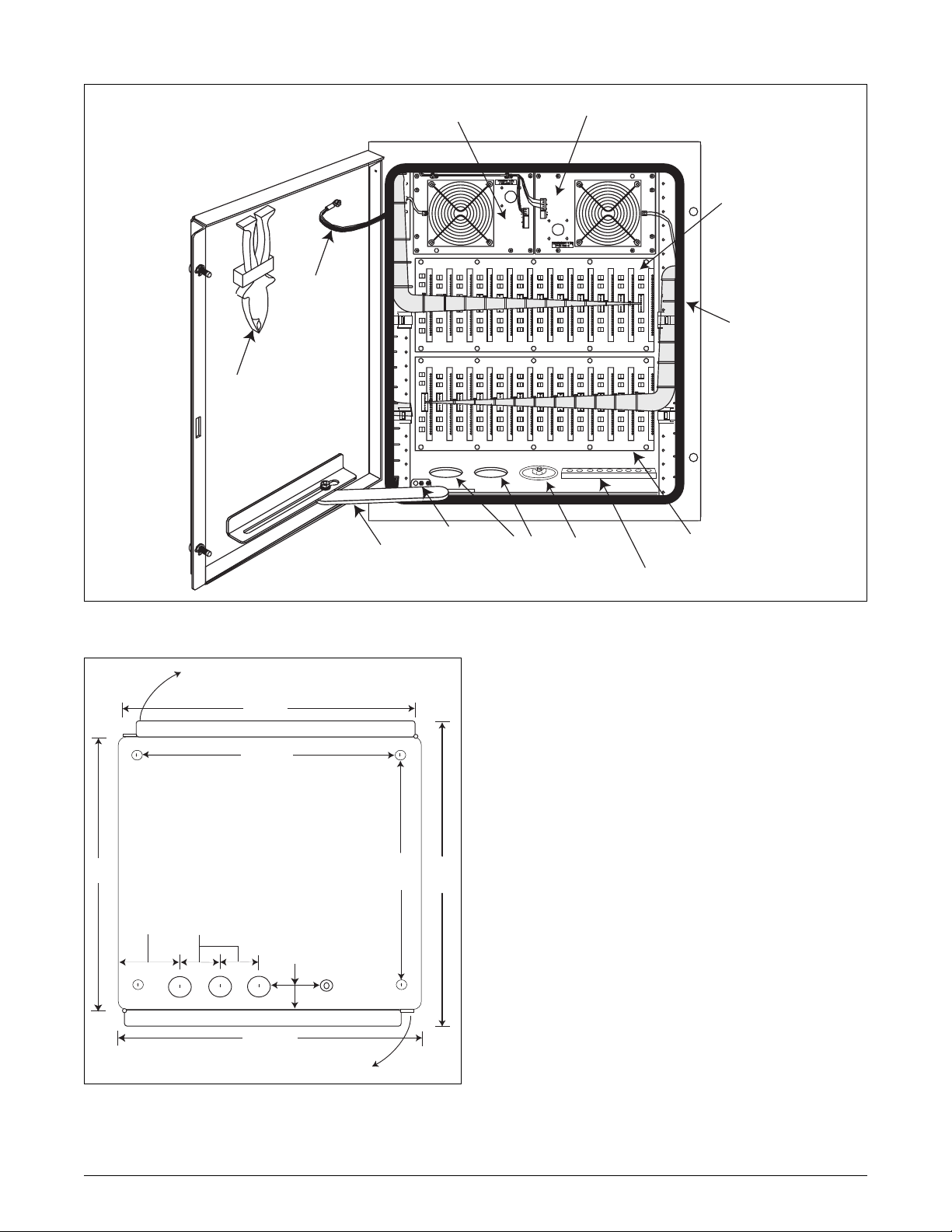
Gas T ube
Extractor
Pliers
Door
Ground
Braid
Pimary
Fan Board
to Cable A
Secondary
Fan Board
to Cable A
Surge Arrestor
Board for top Shelf
Door Gasket
Rear Door
Rear Door
Retainer
Switch
Figure 2. Cabinet Assembly, Rear View
OPEN
23"
Front door
20 7/16"
View is looking down with top cut away.
Mounting bolt hole center lines are 1 5/8" in from each edge.
Ground stud is 1 5/8" from rear edge.
Measurements shown are center to center (C/C).
Door width includes locking flange.
Cable penetrations are 1 7/8" in diameter.
Cabinet is 27" high not including cable stubs.
Pad mount brackets are 18" high.
17"
Dimensions are tape rule derived and measured from
outside the cabinet.
5 3/4"
3 1/4"
C/C
cable dimensions +/- 1/8"
13 3/4"
C/C
20"
overall
2 1/2" C/L
Ground
spare
B
A
Rear door
23 5/8"
overall
Lug
OPEN
Figure 3. Top View Cutaway With Installation
Measurements
A, B, and Spare
Cable Penetrations
Surge Arrestor Board
for bottom Shelf
Ground
Connecting lug on
()
Buss
cabinet bottom
Fan Operation and Indication
Two thermostatically controlled line powered cooling
fans limit heat buildup. The primary fan energizes at
about 110° F. The secondary fan energizes at about
150° F.
Primary and secondary fan board operation is
monitored by the FPU. The following conditions
cause an alarm at the FPU:
• Any fan or fan board not receiving power.
• Secondary fan turning On.
• Open cabinet door.
The single FPU at the CO has a separate power supply
for each fan board. The FPU fits into one slot of the
E220 HTU-C shelf (for HDSL applications).
The FPU is purchased separately. Information on fan
board operation and testing is in Section 3. For
additional details on the FPU refer to I&M Practice:
61150091L1-5. The FPU Practice should be on-hand
at the CO for reference during cabinet testing.
61150090L1-5A Section 61150090L1-5A, Issue 1 3
Page 4

NOTE
Because heat dissipates across the cabinet
surfaces, the cabinet should not be installed
within another enclosure or hut unless such
enclosure has positive ventilation.
Status Indicator LEDs
Each fan board has two status indicator LEDs:
• DOOR LED (Red), verifies that FPU power is
present on the associated fan board.
• FAN LED (Green), verifies the open or closed
position of the fan’s associated thermostat.
The LEDs give positive indication that power is
present to operate the fans and thermostats.
DOOR (Power) LED
Power is present at the corresponding fan board if the
red Door LED turns On when the door is opened as
explained here:
• When the front door is opened, the secondary
fan board red Door LED turns On until the front
door switch is manually disabled or the front
door is closed.
• When the rear door is opened, the primary fan
board red Door LED turns On until the rear door
switch is manually disabled or the rear door is
closed.
2. INSTALLATION
C A U T I O N !
SUBJECT TO ELECTROSTATIC DAMAGE
OR DECREASE IN RELIABILITY.
HANDLING PRECAUTIONS REQUIRED.
The cabinet assembly weighs about 200 pounds. This
Practice assumes that proper lifting devices are on
hand for maneuvering and holding the cabinet in
position until securely mounted.
After unpacking the T200/T400 High Capacity
Cabinet inspect it for damage. If damage is noted file
a claim with the carrier, then contact ADTRAN
Customer Service (refer to Section 5).
WARNING
Never install telephone wiring during a
lightning storm.
If equipment is to be stored for any period of time,
ADTRAN recommends that the equipment be kept in
the original shipping container until arriving at the
installation site.
CAUTION
Although sealed from the elements the cabinet
is not designed to be waterproof and must not
be located where any type of immersion could
occur.
NOTE
The door switch also controls intrusion
detection on the FPU at the CO.
Cabinet location should be selected with the following
in mind:
• Personnel and equipment safety
FAN (Thermostat) LED
The green LEDs indicate that power is present at the
thermostat by being On when the fans are Off.
When the thermostat is Open, the green FAN LED
should be On and the fan should be Off. When the
thermostat is Closed, the FAN LED should be Off and
the fan should be On. FAN LED operation is
independent of door switch status.
• Personnel access
• For cable stubbed versions, the proposed cable
routes should not exceed the 50-foot cable stub
lengths.
• Clearances between the cabinet and adjacent
structures must be adequate for access during
maintenance (refer to pad and pole mount
subsections).
Pad Mount Installation
Pad configuration is designated by the installing
activity. The cabinet shipping box has a printed
template for support bracket bolt hole location. Craft
planning will ensure the pad four bolt pattern matches
4 Section 61150090L1-5A, Issue 1 61150090L1-5A
Page 5
the bracket pattern. Refer to Figure 4 for pad mount
tP.tiKerawdraHtnuoMdaP
#
8-0900512
noitpircseDytitnauQ
sliatedgnitfiL*2
tekcarbgnitnuomdaP2
revoctekcarbgnitnuomdaP2
stloB"1x61-8/34
rehsawtalF8/34
rehsawtilpS8/34
rehsawgnilaeS8/34
swercsytiruceS8
deppihserasliatedgnitfilhcattaotdesusrenetsaF*
.snoitacoltenibacdetangisedriehtotnidetresni-erp
access dimensions.
1. At the installation site remove all packaging
material enclosing the cabinet.
2. Remove and set aside the mounting hardware
kit. Verify contents per Table 2.
3. The cabinet is bolted to two boards running
across the box frame. Remove the screws
securing the two boards to the wood box frame.
4. Attach lifting details. Screwed into each side of
the cabinet is a group of three bolts and washers.
Remove these for reuse.
5. Following the illustration in Figure 5, attach the
lifting details to each side of the cabinet using
the bolt and washer groups. Ensure the sealing
washers are placed between the cabinet and the
lifting details. Tighten bolts to 110-130 in-lbs.
WARNING
When lifting the cabinet out of the shipping
package and during installation, be sure to
exercise caution and observe all safety
measures.
Table 2. Pad Mounting Hardware
CAUTION
Do not reuse shipping hardware. It is not
designed for cabinet mounting.
6. Using appropriately sized and tested hoisting
gear, attach a hoist cable between the two lifting
details. Hoist the cabinet from the package and
lower the cabinet onto its side.
7. Remove all hardware securing the wood
shipping frame to the bottom of the cabinet.
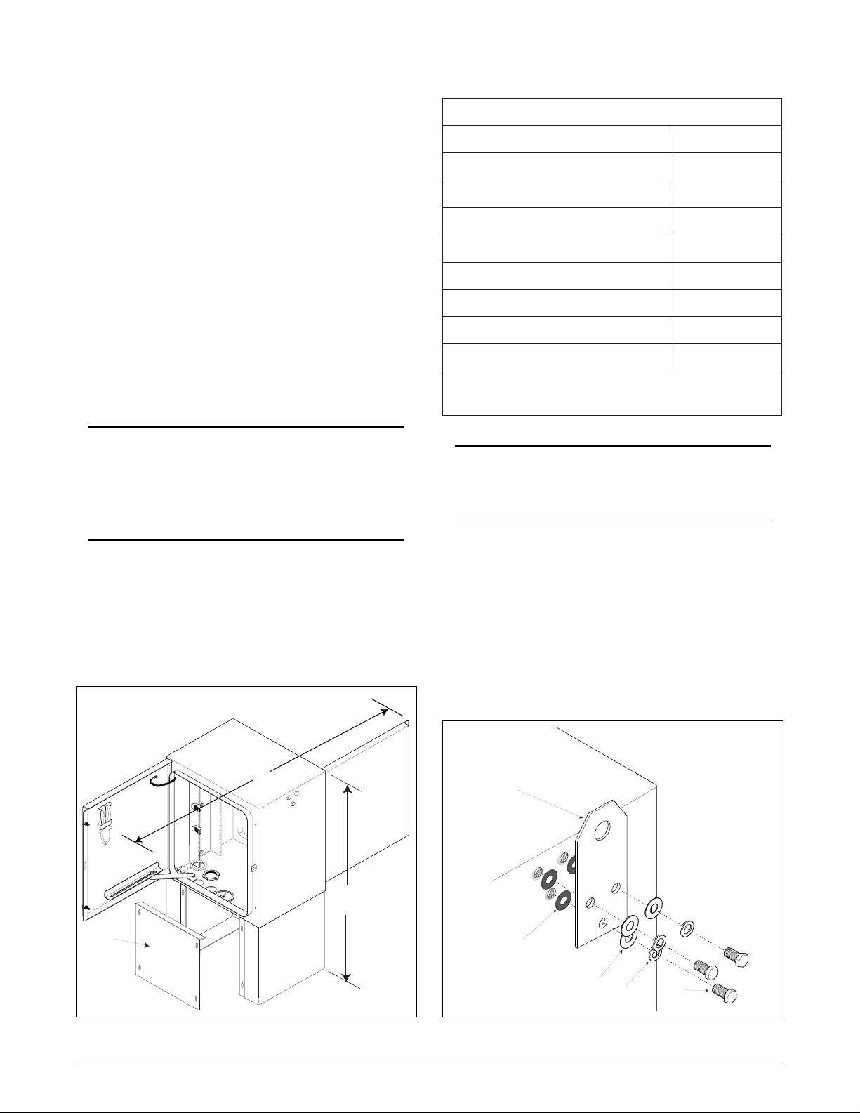
63"
overall with
doors open
45"
total
Security
Access
Cover
8. Following the illustration in Figure 6 and using
the parts supplied in the pad mounting kit, fasten
the two pad mounting brackets to both sides of
the bottom of the cabinet. Ensure the sealing
washers are placed between the cabinet and the
pad mounting brackets. Tighten to
100-110 in-lbs.
One side shown, other
side identical.
lifting detail
Bolt torque:
110-130 in-lbs
sealing washer
flat washer
split washer
bolt
Figure 4. Pad Mount Dimensions
Figure 5. Lifting Detail Assembly
61150090L1-5A Section 61150090L1-5A, Issue 1 5
Page 6
sealing washer
on the pad mounting brackets using the included
fasteners. Tighten to 10-15 in-lbs. Install with
the access cover lip facing in and against the
cabinet’s bottom panel. See Figure 4.
13.If lifting details are to be removed, replace the
fasteners removed in step 4 ensuring the sealing
washers are installed next to the cabinet side
panels.
nut*
split
washer*
flat
washer*
Mounting
Bracket
*Customer supplied
Pad arrangement is representative
Pad mounted stud*
(4 places)
bolt torque:
100-110 in-lbs
5/8" dia
Figure 6. Pad Mounting Bracket Installation
9. Hoist the cabinet to an upright position and
center it over the pad.
CAUTION
The minimum internal bend radius for cable
stubs is nine inches.
10.At this time, on the cable stub model, the cable
stubs should be fed through their designated
conduit or other route per craft plan.
11.Lower the cabinet with attached brackets onto
the pad ensuring the four bottom bracket
5/8 inch bolt holes align with the pad fastener
arrangement. Secure with customer supplied
fasteners. Continue feeding the cable stubs as the
cabinet is lowered.
12.On the ground lug on the cabinet bottom next to
the spare cable penetration attach an
appropriately sized (6 AWG) ground cable to the
most direct path to ground. Ground cable and
connectors are customer supplied.
Pole Mount Installation
Pole mounting has two configurations:
• Mounted to a single pole on either the left or
right side panel.
• H-frame where the cabinet is supported by a
frame arrangement at either the left or right side
panel.
The pole-mount or H-frame support structure must
bear the weight of a fully equipped cabinet (200 Lbs).
The weight and the distance the cabinet will be
installed above the ground determines the type of pole
configuration to be selected. Refer to Figure 7 for
pole mount access clearances.
1. At the installation site remove all packaging
material enclosing the cabinet.
2. Remove and set aside the Mounting Hardware
Kit. Verify kit contents per Table 3.
3. The cabinet is bolted to two boards running
across the wood box frame. Remove the screws
securing the two boards to the wood box frame.
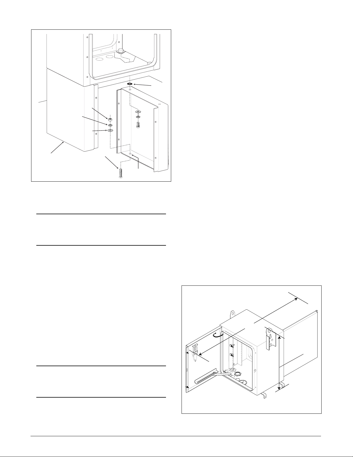
63"
overall with
doors open
33"
top to bottom
brackets included
CAUTION
Without positive ground surge protection is
lost.
13.After the cabinet is secured to the pad the front
and back security access covers can be installed
6 Section 61150090L1-5A, Issue 1 61150090L1-5A
Figure 7. Pole Mount Dimensions
Page 7
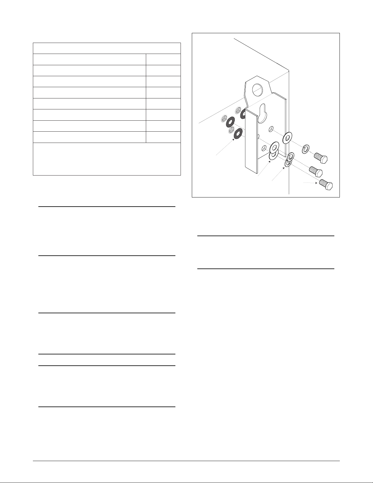
Table 3. Pole Mount Hardware
9-0900512#tPtiktnuomeloP
noitpircseDytitnauQ
liatedgnitfiL*1
)liatedgnitfil(tekcarbtnuomeloP**1
tekcarbtroppusgnitnuomeloP2
stloB"1x61-8/34
rehsawtalF8/36
Mounting Bracket shown,
Lifting Detail similar.
rehsawtilpS8/34
rehsawgnilaeS8/34
deppihserasliatedgnitfilhcattaotdesusrenetsaF*
.snoitacoltenibacdetangisedriehtotnidetresni-erp
gnitfilasasevrestekcarbgnitnuomelopehT**
.noitallatsnignirudliated
4. Attach lifting details. Screwed into each side of
the cabinet is a group of three bolts and washers.
Remove these for reuse.
NOTE
Observe that one of the lifting details is also
the mounting bracket. Ensure the mounting
bracket is attached to the side of the cabinet
designated to be against the pole.
5. Following the illustration in Figure 8, attach the
lifting details to each side of the cabinet using
the bolt and washer groups. Ensure the sealing
washers are placed between the cabinet and the
lifting details. Tighten bolts to 110-130 in-lbs.
WARNING
Exercise caution and observe all safety
measures when lifting the cabinet out of the
shipping package and during installation.
WARNING
Do not disconnect lifting cable until the cabinet
is fully secured and all mounting bracket and
support fasteners are tightened.
6. Using appropriately sized and tested hoisting
gear, attach a hoist cable between the lifting
details. Hoist the cabinet from the package and
lower the cabinet onto its side.
Bolt torque:
110-130 in-lbs
sealing washer
flat washer
split washer
bolt
Figure 8. Mounting Bracket Assembly
7. Remove hardware securing the wooden boards
to the bottom of the cabinet.
CAUTION
Do not reuse shipping hardware. It is not
designed for cabinet mounting.
8. Identify which side of the cabinet will be
mounted to the pole and on that side attach
(finger tight) the slotted end of the two bottom
support brackets. Ensure the short end will point
down after the cabinet is upright and that the
sealing washers are against the bottom of the
cabinet. Refer to Figure 9. Ensure a flat washer
is on both sides of the support bracket.
9. After determining the appropriate upper
mounting height of the cabinet, drill a 5/8” hole
through the pole for the top pole mounting
bracket. The 1/2 inch diameter through-bolt, nut,
and washers are customer supplied. Install the
bolt through the pole and tighten to leave the
bolt head approximately 1 3/4 inches from the
pole to allow the upper pole mounting bracket to
slide over and down, catching the bolt head.
Refer to Figure 10.
10.Maneuver the cabinet so as to fit the through bolt
head through the slot key opening on the
mounting bracket. When the cabinet is hanging
61150090L1-5A Section 61150090L1-5A, Issue 1 7
Page 8

sealing washer
flat washer
split washer
Bolt torque: 100-110 in-lbs
Insert all unused fasteners
bolt
*1/2" Thru-bolt
*3/8" x 2-1/2" Lag Screws (2)
*Customer furnished hardware
Figure 10. Guide for Pole Mounting
*1/2" Nut
*1/2" Washer
Pole Mount
Bracket
Pole Support
Brackets (2)
Figure 9. Bottom Support Bracket Assembly
on the through bolt, the nut on the other end can
be tightened to snug the bolt head to the
mounting bracket. Do not torque at this time.
11.Ensuring the cabinet is secure to the pole, relieve
tension on the hoist device but do not remove.
This allows positioning of the cabinet.
12.At the bottom of the cabinet insert a temporary
spacer between the cabinet and the pole so the
cabinet hangs plumb. The space between the
pole and the cabinet should be the same from top
to bottom.
13.At the bottom of the cabinet, position and angle
the support brackets so the short ends are flush
against the pole. Using a level, ensure the
cabinet is plumb then tighten the bolts (100-110
in-lbs) securing the brackets to the cabinet.
14.Using two 3/8 inch x 2 1/2 inch lag screws
attach the bottom support brackets to the pole.
CAUTION
If bottom bracket adjustment is required,
loosen the bottom support bracket bolts before
adjusting cabinet. Failure to loosen bolts will
cause damage to the sealing washers.
15 Tighten all fasteners to the proper torque.
Remove the lifting gear from the cabinet.
16.If the unused lifting detail is to be removed,
replace the fasteners removed in step 4 ensuring
the sealing washer is installed next to the
cabinet.
NOTE
All unused threaded openings in the cabinet
must have their designated fasteners inserted
and tightened to ensure a proper seal.
H-Frame Mount
For mounting the cabinet to an H-Frame, follow the
same procedure as for Pole Mounting except
substitute acceptable 3/8 inch bolts, nuts, and washers
(customer supplied) instead of lag screws for attaching
the bottom pole mount support brackets to the
H-frame. ADTRAN recommends the use of steel cross
bars between the two poles to ensure adequate
strength. The H-frame facility must be able to bear the
weight of a fully-equipped cabinet (200 Lbs).
Splice Wires (Pre-Stubbed Version or Internal
Splice Module Version)
A T200/T400 Test Access Card (part number
1244065L1, purchased separately) can be inserted into
a slot to assist in circuit or continuity tests. Refer to
ADTRAN Test Access Card Practice, Section
61244065L1-5, for more information.
8 Section 61150090L1-5A, Issue 1 61150090L1-5A
Page 9

CAUTION
Ensure all grounds are securely connected to
the cabinet ground buss and the ground lug
connected to the most direct path to ground.
The following procedures describe wiring connections
for both the stubbed and module connection models:
1. Unscrew the security screws on the front and
rear doors using a 7/16 inch nut driver or
equivalent tool. While loosening the security
screws, alternate between the top and bottom
screws to allow even pressure release.
2. Open the door and allow the door retainer to
engage. The door retainer can be disengaged by
pulling up slightly on the door retainer arm.
3. Manually disable both door alarm switches by
centering the rod and pulling outward.
4. For pre-stubbed cabinets, the top T200/T400
shelf, top surge arrestor board, and the primary
and secondary fan boards are on cable A. The
bottom T200/T400 shelf and bottom surge
arrestor board are on cable B.
diameter range from 0.86 to 1.26 inches. Use care to
ensure correct sequence of assembly.
b. Insert the O-ring evenly in the groove
provided on the sealing grommet.
c. Insert the sealing grommet up through the
designated cable opening until the O-ring is
flush with the bottom of the cabinet.
d. Screw the 1 1/2 inch hex nut onto the sealing
grommet until the O-ring is snug to the bottom
of the cabinet.
e. Using a wrench to hold the sealing grommet
steady, use a second wrench to tighten down
on the hex nut.
f. Screw the compression nut onto the
compression skirt threads, leave the nut loose.
g. Place the shrink-wrap over the cable, let it
slide down out of the way.
h. Insert the cable up through the sealing
grommet providing the correct length of cable
on the inside of the cabinet for splicing.
NOTE
For non-stubbed cables, complete the
following three assembly procedures prior to
completing Step 5.
I. CABLE STUB ENTRY
a. Verify contents of the Cable Stub Entry Kit
per Table 4. The kit is located inside the
mounting kit.
The cable sealing grommet assembly is installed in the
cable opening as shown in Figure 11. The sealing
grommet can accommodate cables with an outside
Table 4. Seal Grommet Kit
51-0900512#tPtiKyrtnEbutSelbaC
noitpircseDytitnauQ
tunnoisserpmoc/wtemmorggnilaeS2
Cabinet
Bottom
Compression
Nut
1 1/2" NPT Hex Nut
O-Ring
Cable
Sealing
Grommet
Compression
Skirt
Cable A or B
(0.86" to 1.26" OD)
Shrink
Wrap 6"
gnir-OtemmorG2
tunxehTPN"2/112
denil-evisehda,knirhs-taeHae"6@2
61150090L1-5A Section 61150090L1-5A, Issue 1 9
Figure 11. Sealing Grommet Assembly
Page 10

NOTE
Refer to Splice Module installation
instructions for the length required inside the
cabinet. Ensure sufficient sheathed cable
exists at the top of the sealing grommet to
install shield connectors.
first nut and tighten until the connector securely
grips the shield and insulator. See view D.
f. Install the ground braid over the stud followed
by the second nut and tighten securely. See view
E. Repeat this process for the remaining cable.
g. Ensure the trailing end of the ground braid is
securely connected to the ground buss.
i. Using a wrench to hold the sealing grommet
steady, use a second wrench to tighten the
compression nut until the compression skirt
creates a weathertight seal around the cable.
II. SHIELDING
On non-stubbed cabinet installations the shield and
braid must be connected to the ground buss as
described in this procedure. Refer to Figure 12 for
views of the connector components, cable, and
assembly sequence. Entry cables have an outer
insulator, a shield sheath, and a core wrap protecting
the inner wire bundle, see View A. The shield sheath
must connect to ground with the supplied connectors
and ground braid.
The connectors and ground braid are temporarily
attached at the factory for cabinet shipment, remove
the connectors from the braid for this procedure.
CAUTION
Ensure wire insulation is not damaged during
shield connection.
Connector
Bottom
A
B
Wire
Bundle
Core
Wrap
Connector Top
Securing Nuts (2)
Shield
Insulator
Shield &
Insulator
C
a. From where the wire bundle exits the cable,
remove about 3/4 inch of insulation and shield
but leaving the protective core wrap intact. See
view B for steps a and b.
b. On the side opposite from where the shield
connector will be placed, make a one inch slice
D
through the insulator and the shield but not the
core wrap. This eases the insertion of the
connector.
c. Opposite the slice, insert the connector bottom
into the cable between the shield and the core
wrap until it reaches the small stop tabs. See
view C for steps c and d.
d. Tap the cable in the area of the leading edge of
the connector to set the contact teeth into the
E
shield
e. Slide the connector top over the stud so it
sandwiches the shield and insulator. Install the
1 0 Section 61150090L1-5A, Issue 1 61150090L1-5A
Figure 12. Shield Connector Assembly
Page 11

III. SHRINK-WRAP
After all other connections are completed, or correct
wire lengths verified, complete the shrink-wrap
process as follows:
a. Position the shrink-wrap up against the bottom
of the cabinet enclosing the entire sealing
grommet assembly.
b. Heat treat the shrink-wrap until properly
constricted around the assembly.
NOTE
On pole mounts, secure the cable exiting the
cabinet to the pole using standard practices
and customer-supplied hardware.
Proceed with Step 5 of the Splice Wires sub section.
5. Insert the circuit pack into the desired slot. The
card’s edge connector is offset and must be
properly aligned to ensure connectivity.
CAUTION
Without positive ground the cabinet does not
provide surge protection.
9. Inspect and clean the door gasket and gasket
sealing area prior to closing the front or rear
doors. If there is visible damage, replace the
door gasket.
10.Tighten the tamper resistant security screws on
the front and rear doors using a 7/16 inch nut
driver or an equivalent tool. While loosening or
tightening the security screws, alternate between
the top and bottom screws to allow even
pressure. Tighten to 10-15 in-lbs. maximum.
CAUTION
The FPU at the CO must be online for fan
operation. For the best cooling results, fully
load the top shelf with circuit cards before
loading the bottom shelf.
6. Connect the wiring in cable stubs based on the
appropriate matching slot used.
7. Refer to Table 5A and 5B for splice module
connections and Table 6A and 6B for Circuit
Technology Configuration charts. Table 5 also
provides circuit and pair identification to
configure the cards listed in the table.
NOTE
2
Refer to the 3M MS
™ Modular Splicing
System Instructions Booklet for splicing and
connecting to 4005-DPM Super Mate
Pluggable Modules.
8. Connect the ground lug on the bottom of the
cabinet to an appropriate 6 AWG ground cable
and earth ground.
61150090L1-5A Section 61150090L1-5A, Issue 1 11
Page 12

Table 5A. Splice Module 1 Table 5B. Splice Module 2
Splice Module #1
X
X
X
X
X
X
X
X
X
X
X
X
X
X
X
X
X
X
X
X
X
X
X
X
X
X
X
X
X
X
X
X
X
X
X
X
X
X
X
X
X
X
X
X
X
X
X
X
X
X
Blue Binder
Group
piTgniR
etihW
eulB
etihW
egnarO
etihW
neerG
etihW
nworB
etihW
etalS
deR
eulB
deR
egnarO
deR
neerG
deR
nworB
deR
etalS
kcalB
eulB
kcalB
egnarO
kcalB
neerG
kcalB
nworB
kcalB
etalS
wolleY
eulB
wolleY
egnarO
wolleY
neerG
wolleY
nworB
wolleY
etalS
teloiV
eulB
teloiV
egnarO
teloiV
neerG
teloiV
nworB
teloiV
etalS
Surge Arrestor
Header Connection
1.1P
1.2P
1.3P
1.4P
1.5P
1.6P
1.7P
1.8P
1.9P
1.01P
1.11P
1.21P
3.1P
3.2P
3.3P
3.4P
3.5P
3.6P
3.7P
3.8P
3.9P
3.01P
3.11P
3.21P
1.1PJ
Ckt Bd Slot
5-1PC
2.1P
5-2PC
2.2P
5-3PC
2.3P
5-4PC
2.4P
5-5PC
2.5P
5-6PC
2.6P
5-7PC
2.7P
5-8PC
2.8P
5-9PC
2.9P
2.01P
2.11P
2.21P
7-1PC
4.1P
7-2PC
4.2P
7-3PC
4.3P
7-4PC
4.4P
7-5PC
4.5P
7-6PC
4.6P
7-7PC
4.7P
7-8PC
4.8P
7-9PC
4.9P
4.01P
4.11P
4.21P
3.1PJ
Connections
51-1PC
51-2PC
51-3PC
51-4PC
51-5PC
51-6PC
51-7PC
51-8PC
51-9PC
5-01PC
51-01PC
5-11PC
51-11PC
5-21PC
51-21PC
31-1PC
31-2PC
31-3PC
31-4PC
31-5PC
31-6PC
31-7PC
31-8PC
31-9PC
7-01PC
31-01PC
7-11PC
31-11PC
7-21PC
31-21PC
+NAFIRP
Used on Cable A only
–NAFIRP
Splice Module #2
X
X
X
X
X
X
X
X
X
X
X
X
X
X
X
X
X
X
X
X
X
X
X
X
X
X
X
X
X
X
X
X
X
X
X
X
X
X
X
X
X
X
X
X
X
X
X
X
X
X
Orange Binder
Group
piTgniR
etihW
eulB
etihW
egnarO
etihW
neerG
etihW
nworB
etihW
etalS
deR
eulB
deR
egnarO
deR
neerG
deR
nworB
deR
etalS
kcalB
eulB
kcalB
egnarO
kcalB
neerG
kcalB
nworB
kcalB
etalS
wolleY
eulB
wolleY
egnarO
wolleY
neerG
wolleY
nworB
wolleY
etalS
teloiV
eulB
teloiV
egnarO
teloiV
neerG
teloiV
nworB
teloiV
etalS
Surge Arrestor
Header Connection
5.1P
5.2P
5.3P
5.4P
5.5P
5.6P
5.7P
5.8P
5.9P
5.01P
5.11P
5.21P
7.1P
7.2P
7.3P
7.4P
7.5P
7.6P
7.7P
7.8P
7.9P
7.01P
7.11P
7.21P
1.4PJ
Ckt Bd Slot
6.1P
6.2P
6.3P
6.4P
6.5P
6.6P
6.7P
6.8P
6.9P
6.01P
6.11P
6.21P
8.1P
8.2P
8.3P
8.4P
8.5P
8.6P
8.7P
8.8P
8.9P
8.01P
8.11P
8.21P
5.4PJ
Connections
14-1PC
74-1PC
14-2PC
74-2PC
14-3PC
74-3PC
14-4PC
74-4PC
14-5PC
74-5PC
14-6PC
74-6PC
14-7PC
74-7PC
14-8PC
74-8PC
14-9PC
74-9PC
14-01PC
74-01PC
14-11PC
74-11PC
14-21PC
74-21PC
55-1PC
94-1PC
55-2PC
94-2PC
55-3PC
94-3PC
55-4PC
94-4PC
55-5PC
94-5PC
55-6PC
94-6PC
55-7PC
94-7PC
55-8PC
94-8PC
55-9PC
94-9PC
55-01PC
94-01PC
55-11PC
94-11PC
55-21PC
94-21PC
+NAFCES
Used on Cable A only
–NAFCES
1 2 Section 61150090L1-5A, Issue 1 61150090L1-5A
Page 13

tkC
#kcaP#kcaP
#kcaP
#kcaP#kcaP
#niP&#niP&
#niP&
#niP&#niP&
daeLelbaC
redniBredniB
redniB
redniBredniB
roloCroloC
roloC
roloCroloC
riaP
##
#
##
piT
eriWeriW
eriW
eriWeriW
roloCroloC
roloC
roloCroloC
gniR
eriWeriW
eriW
eriWeriW
roloCroloC
roloC
roloCroloC
LSDH
ERHERH
ERH
ERHERH
LSDH
R-UTHR-UTH
R-UTH
R-UTHR-UTH
NDSI
R-RTR-RT
R-RT
R-RTR-RT
SDD
R-SDDRTR-SDDRT
R-SDDRT
R-SDDRTR-SDDRT
NDSI
R-eldirBR-eldirB
R-eldirB
R-eldirBR-eldirB
LSDH
DINFDINF
DINF
DINFDINF
51-5,1PC
31-7
74-14
94-55
1R-1T
1R-1T
R-T
R-T
eulB
eulB
egnarO
egnarO
1311
31
etihW
kcalB
etihW
kcalB
eulB
neerG
eulB
neerG
1pooL,tsuC
1pooL,kwtN
2pooL,kwtN
2pooL,tsuC
tsuCoT
1pooL,kwtN
2pooL,kwtN
tsuCmF
CN
CN
kwtN
1TN-tsuC
)XR(tsuCoT
CN
kwtNmF/oT
)XT(tsuCmF
tsuC
1pooL,kwtN
2pooL,kwtN
CN
tsuCoT
kwtN
CN
tsuCmF
51-5,2PC
31-7
74-14
94-55
1R-1T
1R-1T
R-T
R-T
eulB
eulB
egnarO
egnarO
2412
41
etihW
kcalB
etihW
kcalB
egnarO
nworB
egnarO
nworB
1pooL,tsuC
1pooL,kwtN
2pooL,kwtN
2pooL,tsuC
tsuCoT
1pooL,kwtN
2pooL,kwtN
tsuCmF
CN
CN
kwtN
1TN-tsuC
)XR(tsuCoT
CN
kwtNmF/oT
)XT(tsuCmF
tsuC
1pooL,kwtN
2pooL,kwtN
CN
tsuCoT
kwtN
CN
tsuCmF
51-5,3PC
31-7
74-14
94-55
1R-1T
1R-1T
R-T
R-T
eulB
eulB
egnarO
egnarO
3513
51
etihW
kcalB
etihW
kcalB
neerG
etalS
neerG
etalS
1pooL,tsuC
1pooL,kwtN
2pooL,kwtN
2pooL,tsuC
tsuCoT
1pooL,kwtN
2pooL,kwtN
tsuCmF
CN
CN
kwtN
1TN-tsuC
)XR(tsuCoT
CN
kwtNmF/oT
)XT(tsuCmF
tsuC
1pooL,kwtN
2pooL,kwtN
CN
tsuCoT
kwtN
CN
tsuCmF
51-5,4PC
31-7
74-14
94-55
1R-1T
1R-1T
R-T
R-T
eulB
eulB
egnarO
egnarO
4614
61
etihW
wolleY
etihW
wolleY
nworB
eulB
nworB
eulB
1pooL,tsuC
1pooL,kwtN
2pooL,kwtN
2pooL,tsuC
tsuCoT
1pooL,kwtN
2pooL,kwtN
tsuCmF
CN
CN
kwtN
1TN-tsuC
)XR(tsuCoT
CN
kwtNmF/oT
)XT(tsuCmF
tsuC
1pooL,kwtN
2pooL,kwtN
CN
tsuCoT
kwtN
CN
tsuCmF
51-5,5PC
31-7
74-14
94-55
1R-1T
1R-1T
R-T
R-T
eulB
eulB
egnarO
egnarO
5715
71
etihW
wolleY
etihW
wolleY
etalS
egnarO
etalS
egnarO
1pooL,tsuC
1pooL,kwtN
2pooL,kwtN
2pooL,tsuC
tsuCoT
1pooL,kwtN
2pooL,kwtN
tsuCmF
CN
CN
kwtN
1TN-tsuC
)XR(tsuCoT
CN
kwtNmF/oT
)XT(tsuCmF
tsuC
1pooL,kwtN
2pooL,kwtN
CN
tsuCoT
kwtN
CN
tsuCmF
51-5,6PC
31-7
74-14
94-55
1R-1T
1R-1T
R-T
R-T
eulB
eulB
egnarO
egnarO
6816
81
deR
wolleY
deR
wolleY
eulB
neerG
eulB
neerG
1pooL,tsuC
1pooL,kwtN
2pooL,kwtN
2pooL,tsuC
tsuCoT
1pooL,kwtN
2pooL,kwtN
tsuCmF
CN
CN
kwtN
1TN-tsuC
)XR(tsuCoT
CN
kwtNmF/oT
)XT(tsuCmF
tsuC
1pooL,kwtN
2pooL,kwtN
CN
tsuCoT
kwtN
CN
tsuCmF
51-5,7PC
31-7
74-14
94-55
1R-1T
1R-1T
R-T
R-T
eulB
eulB
egnarO
egnarO
7917
91
deR
wolleY
deR
wolleY
egnarO
nworB
egnarO
nworB
1pooL,tsuC
1pooL,kwtN
2pooL,kwtN
2pooL,tsuC
tsuCoT
1pooL,kwtN
2pooL,kwtN
tsuCmF
CN
CN
kwtN
1TN-tsuC
)XR(tsuCoT
CN
kwtNmF/oT
)XT(tsuCmF
tsuC
1pooL,kwtN
2pooL,kwtN
CN
tsuCoT
kwtN
CN
tsuCmF
Table 6A. Circuit Technology Configuration Chart (Part 1)
61150090L1-5A Section 61150090L1-5A, Issue 1 13
Page 14

#kcaP
#niPdna#niPdna
#niPdna
#niPdna#niPdna
daeLelbaC
redniBredniB
redniB
redniBredniB
roloCroloC
roloC
roloCroloC
riaP
##
#
##
piT
eriWeriW
eriW
eriWeriW
roloCroloC
roloC
roloCroloC
gniR
eriWeriW
eriW
eriWeriW
roloCroloC
roloC
roloCroloC
LSDH
ERHERH
ERH
ERHERH
LSDH
R-UTHR-UTH
R-UTH
R-UTHR-UTH
NDSI
R-RTR-RT
R-RT
R-RTR-RT
SDD
R-SDDRTR-SDDRT
R-SDDRT
R-SDDRTR-SDDRT
NDSI
R-eldirBR-eldirB
R-eldirB
R-eldirBR-eldirB
LSDH
DINFDINF
DINF
DINFDINF
51-5,8PC
31-7
74-14
94-55
1R-1T
1R-1T
R-T
R-T
eulB
eulB
egnarO
egnarO
8028
02
deR
wolleY
deR
wolleY
neerG
etalS
neerG
etalS
1pooL,tsuC
1pooL,kwtN
2pooL,kwtN
2pooL,tsuC
tsuCoT
1pooL,kwtN
2pooL,kwtN
tsuCmF
CN
CN
kwtN
1TN-tsuC
)XR(tsuCoT
CN
kwtNmF/oT
)XT(tsuCmF
tsuC
1pooL,kwtN
2pooL,kwtN
CN
tsuCoT
kwtN
CN
tsuCmF
51-5,9PC
31-7
74-14
94-55
1R-1T
1R-1T
R-T
R-T
eulB
eulB
egnarO
egnarO
9129
12
deR
teloiV
deR
teloiV
nworB
eulB
nworB
eulB
1pooL,tsuC
1pooL,kwtN
2pooL,kwtN
2pooL,tsuC
tsuCoT
1pooL,kwtN
2pooL,kwtN
tsuCmF
CN
CN
kwtN
1TN-tsuC
)XR(tsuCoT
CN
kwtNmF/oT
)XT(tsuCmF
tsuC
1pooL,kwtN
2pooL,kwtN
CN
tsuCoT
kwtN
CN
tsuCmF
51-5,01PC
31-7
74-14
94-55
1R-1T
1R-1T
R-T
R-T
eulB
eulB
egnarO
egnarO
012201
22
deR
teloiV
deR
teloiV
etalS
egnarO
etalS
egnarO
1pooL,tsuC
1pooL,kwtN
2pooL,kwtN
2pooL,tsuC
tsuCoT
1pooL,kwtN
2pooL,kwtN
tsuCmF
CN
CN
kwtN
1TN-tsuC
)XR(tsuCoT
CN
kwtNmF/oT
)XT(tsuCmF
tsuC
1pooL,kwtN
2pooL,kwtN
CN
tsuCoT
kwtN
CN
tsuCmF
51-5,11PC
31-7
74-14
94-55
1R-1T
1R-1T
R-T
R-T
eulB
eulB
egnarO
egnarO
113211
32
kcalB
teloiV
kcalB
teloiV
eulB
neerg
eulB
neerG
1pooL,tsuC
1pooL,kwtN
2pooL,kwtN
2pooL,tsuC
tsuCoT
1pooL,kwtN
2pooL,kwtN
tsuCmF
CN
CN
kwtN
1TN-tsuC
)XR(tsuCoT
CN
kwtNmF/oT
)XT(tsuCmF
tsuC
1pooL,kwtN
2pooL,kwtN
CN
tsuCoT
kwtN
CN
tsuCmF
51-5,21PC
31-7
74-14
94-55
1R-1T
1R-1T
R-T
R-T
eulB
eulB
egnarO
egnarO
214221
42
kcalB
teloiV
kcalB
teloiV
egnarO
nworB
egnarO
nworB
1pooL,tsuC
1pooL,kwtN
2pooL,kwtN
2pooL,tsuC
tsuCoT
1pooL,kwtN
2pooL,kwtN
tsuCmF
CN
CN
kwtN
1TN-tsuC
)XR(tsuCoT
CN
kwtNmF/oT
)XT(tsuCmF
tsuC
1pooL,kwtN
2pooL,kwtN
CN
tsuCoT
kwtN
CN
tsuCmF
noitcnuFdaeL
elbaC
redniBredniB
redniB
redniBredniB
roloCroloC
roloC
roloCroloC
riaP
##
#
##
piT
eriWeriW
eriW
eriWeriW
roloCroloC
roloC
roloCroloC
gniR
eriWeriW
eriW
eriWeriW
roloCroloC
roloC
roloCroloC
:SETON
.flehsehtedisnirebmunkcaptiucricehtsi#PC.1
.detcennoCtoN=CN.2
.dnuorGsirotcennocegdedrachcaefo11niP.3
.pudliubtaehtneverpotlanoitcnufebtsumsnaF.4
.metsysgniloocnafrotinomdnarewopotderiuqersiUPFdellatsniOCehT.5
.yletarapesdesahcrupsitinUgnirewoPnaFehT.6
.sdraobnafhtobdnaflehs004Tpotehtotstcennoc"A"elbaC.7
.flehs004Tmottobehtotstcennoc"B"elbaC.8
.hcaestols21evahsevlehs004TowtehT.9
.draobrotserraegrusnwostisahflehshcaE.01
.noitamrofniremotsucdrocerottnemucodsihtfodneehtta8elbaTesU.11
naFyramirP
/soP
geN
eulB52teloiVetalS
"A"elbaC
ylnO
yradnoceS
naF
/soP
geN
egnarO52teloiVetalS
"A"elbaC
ylnO
sriaPerapS
eulB
eulB
egnarO
egnarO
1#PS
2#PS
1#PS
2#PS
etihW
etihW
etihW
etihW
deR
kcalB
deR
kcalB
1 4 Section 61150090L1-5A, Issue 1 61150090L1-5A
Table 6B. Circuit Technology Configuration Chart (Part 2)
Page 15

3. TESTING General
Each test identifies a particular malfunction. For that
reason associated components used to isolate a
malfunction are assumed to be functioning correctly.
Certain troubleshooting requires personnel at both the
Central Office to monitor the FPU, and field personnel
at the cabinet to determine if a fault condition exists.
Refer to Figure 13 to identify fan board component
locations.
Fan Board Indication
Each fan board has two status indicator lights:
• DOOR (Red) LED (Power and Door Alarm
indication)
• FAN (Green) LED (Thermostat position)
Door Switch
Front and rear door switches are identical. The
following description applies to both. The door switch
responds to three conditions:
• Door closed
• Door open
• Manual override
When the door is closed the switch contacts are closed
allowing power to the fan.
When the door is opened the switch contacts open
securing power to the fan. Board circuitry recognizes
the condition and sends a door open “intrusion
notification” alarm to the FPU at the CO, and also
turns the door LED On at the corresponding fan
board.
Manual override is electrically identical to the door
closed condition.
During cabinet maintenance the manual override (or
closing the door) resets the alarm at the FPU.
Indication that the alarm has reset is by the
corresponding door LED turning Off.
Verify Power at the Fan Boards
Power is present at the corresponding fan board if the
red Door LED comes On when the door is opened.
Verify that the primary fan board is receiving power:
1. Push-in and release the rear door switch.
2. If the primary fan board Door LED goes On, the
primary fan board has power. At the CO the
FPU Door Alarm LED will turn red.
3. Disable the rear door switch by centering the rod
and pulling outward. The primary fan board
Door LED should go Off and the Door Alarm
LED at the FPU will turn green.
Verify that the secondary fan board is receiving
power:
1. Push-in and release the front door switch.
2. If the secondary fan board Door LED turns On,
the secondary fan board has power. At the CO
the FPU Door Alarm LED will turn red.
To Rear
Door Switch
JP2
Pimary
Fan Board
to Cable A
Rear
Door LED
Fan LED
(thermostat)
Thermostat
JP4
JP1
Thermostat
Secondary
Fan Board
to Cable A
Fan LED
(thermostat)
Front
Door LED
JP2
To Front
Door Switch
Figure 13. Primary & Secondary Fan Boards
61150090L1-5A Section 61150090L1-5A, Issue 1 15
Page 16

3. Disable the front door switch by centering the
rod and pulling outward. The secondary fan
board Door LED should go Off and the Door
Alarm LED at the FPU will turn green.
Fan Operation
When the cabinet is initially installed without heat
generating circuit packs, the primary and secondary
fans will not automatically turn On. Fan board
thermostats control the On/Off fan cycle when the
interior temperature reaches the thermostat’s set
points.
• The primary thermostat Closes at about 110° F
increasing and Opens at about 80° F decreasing.
• The secondary thermostat Closes at about 150° F
increasing and Opens at about 120° F
decreasing.
• Thermostat set points may vary slightly from
stated temperatures.
When the primary and secondary fan boards are
initially wired and connected to the Central Office
FPU, both the primary and secondary fan board
thermostat (Green) LEDs should be On and the fans
should be Off. This indicates that both of the fan
board thermostats are Open.
If the thermostat was Closed, the thermostat LED
would be Off and the fans would be On (if the
temperature was within the thermostat’s Closed
operating range). The thermostat LED’s operation is
independent of the door switch status.
Verify Proper Connections
Test to ensure that changes to the primary fan board
will cause changes to the associated LEDs at the
Central Office FPU:
NOTE
This test specifies the rear door/primary fan
board. Test the front door/secondary fan
board by conducting a similar process.
1. Disable the rear door switch by centering the rod
and pulling outward. The primary fan board
Door LED should go Off.
WARNING
High voltages are present on exposed pins.
DO NOT contact exposed surfaces.
2. On the primary fan board, disconnect the JP1
connector by pulling the connector out of the
header. DO NOT PULL ON WIRES.
- At the Central Office FPU, the PRI FAN LED
will turn red (alarm condition). This verifies
the primary fan board connections are correct.
- If the PRI FAN LED at the FPU does not turn
red, the connections are incorrect.
- If the secondary FPU SEC FAN LED turns on
red, the circuits are crossed between the
cabinet and the FPU.
3. Align and reconnect the JP1 connector.
NOTE
If the primary and secondary fan powering
cable pairs are reversed at either the Central
Office or at the cabinet, the primary fan will
still go On at 110
° F but the Central Office
FPU will indicate that the SEC FAN is
running. This is an ALARM condition at the
FPU.
Abnormal Condition Turning the Secondary
Fan On
Any condition that causes the secondary fan to turn
On is considered abnormal. The following conditions
will allow heat buildup causing the secondary fan
thermostat to eventually Close:
• The primary fan cannot keep up with heat load.
• The primary fan or fan board is not functioning.
• The circuitry between the FPU and the primary
fan board has opened, shorted, or otherwise
malfunctioned.
• The FPU at the CO is not providing power to the
primary fan board.
• Additionally, the secondary fan thermostat may
not be operating properly.
Fan Board Troubleshooting
If troubleshooting a fan board malfunction, fan board
operation should be examined during the hottest time
of the day before the outside temperature drops.
The cabinet internal temperature may stabilize slowly
or quickly depending on the outside air temperature,
wind conditions, exposure to the sun, shading during a
particular time of day, and also the number of circuits
installed inside the cabinet.
1 6 Section 61150090L1-5A, Issue 1 61150090L1-5A
Page 17

If the cabinet has been opened during the day allowing
the heat to escape before proper troubleshooting tests
could be conducted, close the cabinet doors and allow
the cabinet internal temperature to restabilize.
Recheck during the hottest time of the following day
before the outside temperature has a chance to drop.
PRIMARY FAN BOARD
If the primary fan board is believed to be damaged,
check the following in the listed order immediately
upon opening the rear door:
• Power is present at the fan board. (Door LED
turns On as soon as the rear door is opened.) If
the door LED does not turn On, troubleshoot for
lack of power.
• Manually disable the rear door switch and check
the fan LED status:
- If the primary fan LED is Off, the primary fan
should be On.
- If the primary fan LED is On, the primary fan
should be Off.
• If either condition does not exist the primary fan
board is suspect and should be replaced.
SECONDARY FAN BOARD
If the secondary fan board is believed to be damaged,
check the following in the listed order immediately
upon opening the rear door:
• Power is present at the fan board. (Door LED
turns On as soon as the front door is opened.) If
the door LED does not turn On, troubleshoot for
lack of power.
• Manually disable the front door switch and
check the fan LED status:
- If the secondary fan LED is Off, the secondary
fan should be On.
- If the secondary fan LED is On, the secondary
fan should be Off.
• If either condition does not exist the secondary
fan board is suspect and should be replaced.
Open Loop/No Continuity
The primary or secondary Door LEDs will remain Off
when the rear or front door is opened if the respective
primary or secondary power loop has no continuity
(Open) between the cabinet and the FPU.
1. Verify the Central Office FPU is online.
2. Check the LED indication on the FPU.
3. If the FPU is sending power but the cabinet is
not receiving it, check the wiring connections at
both the cabinet and the FPU.
Shorted Loop
The primary or secondary Door LEDs will remain Off
when the rear or front doors are opened if the
respective primary or secondary fan powering loop
has a short across the tip/ring cable pair between the
cabinet and the Central Office FPU.
1. Verify the Central Office FPU is online.
2. Check the LED indication on the FPU.
3. If the FPU is sending power but the cabinet is
not receiving it, check the wiring connections at
both the cabinet and the FPU.
Door Switch Troubleshooting
Door switches can fail in either the Closed or Open
position. The next two procedures will identify the
particular failure. The procedure applies to both front
and rear door switches.
WARNING
High Voltages are present on exposed pins.
Do not contact exposed surfaces.
Door Switch Failure-Closed
1. Verify with the CO that the FPU is online.
2. Push in and release the door switch.
3. If the Door LED is On, the door switch is not
defective.
4. If the Door LED stays Off, regardless of the
door switch position, proceed with Step 5.
5. Disconnect the JP2 door switch connector on the
fan board by carefully pulling the connector off
the header. DO NOT PULL ON WIRES.
6 If the Door LED turns On, the corresponding
door switch is defective.
7. Follow the door switch replacement instructions
to replace the defective door switch.
Door Switch Failure-Open
1. Verify with the CO that the FPU is online.
2. Push in and release the door switch. The Door
LED should go On.
3. Manually disable the door switch by centering
the rod and pulling outward.
4. The Door LED should go Off.
5. If the Door LED stays On regardless of switch
position, proceed with Step 6.
61150090L1-5A Section 61150090L1-5A, Issue 1 17
Page 18

6. Disconnect the door switch JP2 connector on the
Typical removal
or replacement
shown.
fan board by carefully pulling the connector off
the header. DO NOT PULL ON WIRES.
7. Take an insulated ball-clip or alligator-clip and
short across the two exposed door switch JP2
connector pins at the fan board.
8. If the Door LED goes Off, the door switch is
defective.
9. Follow the door switch replacement Instructions
to replace the defective door switch.
NOTE
Refer to the Fan Powering Unit I&M Practice:
61150091L1-5, for additional details on the
FPU.
4. MAINTENANCE
Maintenance consists of replacement of surge arrester
gas tubes, door gaskets, or other replaceable items.
Fan board repairs should not be attempted in the field.
Repair services are obtained by returning the defective
unit to ADTRAN Customer Service.
Surge Arrester Replacement
Each slot in the T200/T400 shelf has four associated
surge arrestor gas tubes (Figure 14) for surge
protection. Surge protection is provided by
replaceable gas surge arrestor tubes. Perform the
following procedure to replace gas tubes:
WARNING
Prevent electrical shock during maintenance
by removing the appropriate slot powering
modules and tagging out to prevent
inadvertent insertion.
1. At the CO, remove the appropriate power
module to deenergize the associated slot at the
cabinet.
2. Grasp one gas tube and remove it using the gas
tube pliers supplied with the cabinet, see
Figure 15.
3. Insert a replacement gas tube in the same
position.
Refer to Table 7 for a list of replacement item part
numbers.
Table 7. Replacement Item Part Numbers
noitpircseDrebmuNtraP
gaB.zO8,tnacciseD1008613
sebuTsaG1006813
looTtcartxE/tresnIebuTsaG2409623
draoBnaFyramirP5-0900512
draoBnaFyradnoceS6-0900512
tiKtnuoMdaP8-0900512
tiKtnuoMeloP9-0900512
)"62.1-68.0(tiKtnuoMbutSelbaC51-0900512
tiKriapeRteksaGrooD61-0900512
tiKriapeRhctiwSrooD71-0900512
Desiccant Renewal
Each cabinet is shipped with two moisture absorbing
desiccant bags inside the cabinet. To ensure continued
moisture absorption the desiccant must be renewed
periodically, depending on the environment.
P12
P11
Slot 12,
Gas T ubes
Slot 12,
Connection
to Cable
P10
P9
P7
P8
P6
Slot 1,
Connection
to Cable
P5
P4
Figure 14. Surge Arrestor Board
Figure 15. Surge Arrestor Gas Tube
Replacement
P3
P2
P1
Slot 1,
Gas T ubes
1 8 Section 61150090L1-5A, Issue 1 61150090L1-5A
Page 19

4. Replace the remaining gas tubes in the same
manner. Each slot has four gas tubes.
5. Untag and reinsert the associated slot power
module at the CO.
6. Perform circuit tests to verify proper circuit
operation.
WARNING
Provide adequate ventilation when using
sealant. Do not inhale vapors. Avoid contact
with the skin. Follow all sealant
manufacturers instructions.
NOTE
If lightning is the suspected cause of circuit
pack failure, ADTRAN recommends
replacing all the surge arrestor gas tubes.
Door Gasket Replacement
The door gasket provides a weathertight seal. Routine
preventive maintenance includes cleaning the seal and
seal area when the cabinet door is opened. A
deteriorated or damaged gasket should be replaced
using the following procedure:
WARNING
Follow all manufacturers safety precautions,
directions, and other label warnings or
information when using gasket sealing
compound. Follow all application directions
to ensure a proper seal.
1. Remove damaged door gasket.
2. Thoroughly clean the gasket sealing area on the
door and the gasket flange using a soap solution.
Rinse and dry. Do not use solvents or chemical
agents that could damage the surface finish.
3. Install the replacement gasket to the gasket
flange with the joining ends at the bottom center
of the flange. Note that the replacement gasket
has vent holes. Install the gasket such that the
vent holes are on the cabinet interior side of the
gasket mounting flange.
4. Totally install the gasket to determine proper
circumference fit. If a small gap appears at the
joining ends the gasket can be slightly stretched
starting at the top and working towards the
bottom. Reverse this process if an overlap exists.
Continue this manipulation until the gasket ends
fit flush.
5. Where the gasket joins, on each side pull about 6
inches of gasket away from the flange.
6. An insert gasket “rope” provides a bonding
medium, gasket support, and end alignment.
CAUTION
The alignment rope is sized to fit equally
between the two ends of the gasket without
blocking the vent holes. During assembly keep
the rope equally positioned between the two
gasket ends.
Apply a small amount of sealant around one end
of the rope and slide it halfway into the gasket
core (either end).
CAUTION
Excessive sealant will decrease adhesion and
cause longer cure time. Inadequate sealant
will cause gaps allowing moisture penetration.
7. Apply a thin bead of sealant on the gasket
mating end. A proper seal requires a complete
sealant bead without breaks.
8. Carefully mate the two ends allowing the
alignment rope to slide into the gasket core on
the adjoining end until the two gasket ends meet
as seamless as possible. A small amount of
sealant should extrude around the mating edges.
9. Immediately install the gasket onto the flange to
maintain alignment and positive end contact.
Hold the gasket in this position for 2 minutes (or
manufacturer’s directions).
10.Inspect the gasket joint. If any sealant gaps are
visible a thin coat of sealant can be applied to fill
the gap.
11.Follow the sealant manufacture’s directions for
cure time (about 6 to 8 hours or until surface is
not tacky).
12.Do not close the door until the joint is totally
cured. This prevents the door from sticking to
the gasket on the next opening.
To ensure cabinet integrity it is important that the
joined surface that contacts the door when it is shut be
free of irregularities.
61150090L1-5A Section 61150090L1-5A, Issue 1 19
Page 20

Door Switch Replacement
The door switch can be replaced in the field if it is
damaged or becomes defective.
WARNING
High Voltages are present on exposed pins.
Do not contact exposed surfaces.
The following procedure applies to either the front or
rear door switch (Figure 16):
1. On the affected switch trace the wires to the fan
board JP2 connector. Disconnect by pulling the
connector out of the header. DO NOT PULL ON
WIRES.
2. Remove the two slide-on terminal connectors on
the switch by grasping the heat-shrink insulation
and sliding away from the switch. DO NOT
PULL ON WIRES.
3. Remove the two Phillips head screws that secure
the switch to the cabinet flange and remove the
switch.
4. On the replacement switch, identify the COM
(common) and NO (normally open) terminals.
5. Position and correctly orient the replacement
switch then insert and tighten the two Phillips
head screws.
6. Note that one slide-on connector has notched
insulation. Slide that connector onto the COM
terminal such that the notched side is against the
switch.
Phillips head screws
COM
7. Slide the remaining connector onto the NO
terminal.
8. At the other end insert the connector into the fan
board JP2 header.
9. Conduct a functional test to verify proper door
switch operation.
Customer Identification
To easily identify the customer and record circuit
information, Table 8 is provided for placement in the
plastic holder inside the front door of the cabinet. The
Table can be updated when circuits are connected or
changed.
5. WARRANTY AND CUSTOMER SERVICE
ADTRAN will replace or repair this product within
five years from the date of shipment if it does not
meet its published specifications or fails while in
service (see: ADTRAN Carrier Network Equipment
Warranty, Repair, and Return Policy and Procedure,
document: 60000087-10A).
Contact Customer And Product Service (CAPS) prior
to returning equipment to ADTRAN.
For service, CAPS requests, or further information,
contact one of the following numbers:
ADTRAN Technical Support
(800) 726-8663
Standard hours: Monday-Friday, 7 a.m.-7 p.m. CST
Emergency hours: 7 days/week, 24 hours/day
ADTRAN Sales
(800) 827-0807
ADTRAN Repair/CAPS
(256) 963-8722
Repair and Return Address
ADTRAN, Inc.
CAPS Department
901 Explorer Boulevard
Huntsville, Alabama 35806-2807.
NO
View from inside cabinet
Figure 16. Door Switch
2 0 Section 61150090L1-5A, Issue 1 61150090L1-5A
Page 21

Table 8. Customer & Circuit Information
flehSpoT
#tolS#tolS
#tolS#tolS
#tolS
emaNremotsuC.D.ItiucriCetuoRmetsyS#metsySepyTtiucriC
1
2
3
4
5
6
7
8
9
01
11
21
flehSmottoB
#tolS#tolS
#tolS#tolS
#tolS
emaNremotsuC.D.ItiucriCetuoRmetsyS#metsySepyTtiucriC
1
2
3
4
5
6
7
8
9
01
11
21
:SETON
61150090L1-5A Section 61150090L1-5A, Issue 1 21
 Loading...