

Page 1

QS2 Series
Low-voltage Servo Drive
Page 2
2
QS2 Series Low-voltage Servo Drive
Basic Information
This Manual is written by Adtech (Shenzhen) Technology Co., Ltd.
This Manual is mainly written by: Zeng Jinbo
This Manual was first released on September 8, 2012, with version No. C00 and item number QS208020M.
Copyright Notice
The property rights of all the parts of the manual belong to Adtech (Shenzhen) Technology Co., Ltd. (Adtech for
short), and any form of imitation, copying, transcription or translation by any company or individual without the
permission is prohibited. This manual does not include any form of assurance, standpoint expression, or other
intimations. Adtech and the stuffs have no responsibility for any direct or indirect disclosure of the information,
benefit loss or business termination of this manual of the quoted product information. In addition, the product
and the information mentioned in this manual are for reference only, and the content is subject to change without
notice.
ALL RIGHTS RESERVED!
Adtech (Shenzhen) Technology Co., Ltd.
Page 3
3
QS2 Series Low-voltage Servo Drive
Precautions
※ Transport and storage
Do not stack product package more than six layers;
Do not climb, stand on or place heavy stuff on the product package;
Do not pull the cable still connecting with machine to move product.
Forbid impact and scratch on the panel and display;
Prevent the product package from humidity, sun exposure, and rain.
※ Open-box inspection
Open the package to confirm the product to be purchased by you.
Check damages situation after transportation;
Confirm the integrity of parts comparing with the parts list or damages situation;
Contact our company promptly for discrepant models, shortage accessories, or transport
damages.
※ Wiring
Ensure the persons involved into wiring and inspecting are specialized staff;
Guarantee the product is grounded with less than 4Ω grounding resistance. Do not use neutral
line (N) to substitute earth wire.
Ensure grounding to be correct and solid, in order to avoid product failures or unexpected
consequences;
Connect the surge absorption diodes to the product in the required direction, otherwise, the
product will be damaged;
Ensure the power switch is OFF before inserting or removing plug, or disassembling chassis.
※ Overhauling
Ensure the power is OFF before overhauling or components replacement;
Page 4
4
QS2 Series Low-voltage Servo Drive
Make sure to check failures after short circuit or overloading, and then restart the machine
after troubleshooting
Do not allow to frequently connect and disconnect the power, and at least one minute interval
between power-on and power-off.
※ Miscellaneous
Do not open housing without permission;
Keep power OFF if not in use for a long time;
Pay close attention to keep dust and ferrous powder away from control;
Fix freewheel diode on relay coil in parallel if non-solid state relay is used as output relay.
Check whether power supply meets the requirement to ensure not burning the control.
Install cooling fan if processing field is in high temperature, due to close relationship between
service life of the control and environmental temperature. Keep proper operative temperature
range for the control: 0℃ ~ 60℃.
Avoid using the product in the overheating, humid, dusty, or corrosive environments;
Add rubber rails as cushion on the place with strong vibration.
※ Maintenance
Please implement routine inspection and regular check upon the following items, under the
general usage conditions (i.e. environmental condition: daily average 30℃, load rate: 80%,
and operating rate: 12 hours/ day)
Routine Inspection
Routine
● Confirm environmental temperature, humidity,
dust, or foreign objects.
● Confirm abnormal vibration and noise;
● Check whether vents are blocked by yarn etc.
Regular Check
One year
● Check whether solid components are loose
● Confirm whether terminal block is damaged
Page 5
5
QS2 Series Low-voltage Servo Drive
Contents
Chapter 1 Product Inspection and Information .......................................................... 7
1.1 Product Inspection ............................................................................................ 7
1.2 Naming Convention of Servo Motor and Drive ............................................... 8
1.2.1 Nomination for Servo Drive
......................................................................... 8
1.3 Reference Table of Servo Motor and Servo Drive ........................................... 8
1.4 Features of QS2 Series Servo Drive ................................................................. 9
1.5 Technical Specification of Servo Drive ............................................................ 9
Chapter 2 Installation ................................................................................................. 11
2.1 Installation of Servo Drive ............................................................................. 11
2.1.1
Installing Environmental Conditions
...................................................... 11
2.1.2
Installation Method and Dimensions ....................................................... 12
2.2 Installation of Servo Motor ............................................................................ 13
2.2.1
Installing Environmental Conditions
...................................................... 13
2.2.2
Definition of Motor Rotation Direction
.................................................. 14
Chapter 3 Wiring ...................................................................................................... 15
3.1 Overall Wiring Diagram ................................................................................. 15
3.2 Name and Function of Terminals ................................................................... 17
3.2.1. Introduction of Interface ......................................................................... 17
3.2.2. Details on Interface ................................................................................. 18
3.3 Principle of Input and Output Interface .......................................................... 22
3.3.1
Switch
EN-, MODE-, CW-, CCW-, ALRS- Input Interface
........................... 22
3.3.2 Switch ALM, COIN Output Interface .................................................. 23
3.3.3 Pulsing
Signal Inlet Interface .................................................................. 23
3.3.4
Analog Quantity Input Interface ............................................................... 25
Chapter 4 LED Alarm Indicator and Dial Switch ..................................................... 26
4.1 LED Indicator Light ........................................................................................ 26
4.1.1
Red Indicator Light ................................................................................... 26
4.1.2
Green Indicator Light ............................................................................... 26
4.2 Dial Switch ...................................................................................................... 27
Page 6

6
QS2 Series Low-voltage Servo Drive
Chapter 5 Drive and Computer Communication ................................................ 28
5.1 Installation of USB-RS485/RS232 Drive ....................................................... 28
5.2 Parameter Setting of Drive Software .............................................................. 33
5.3 Parameter Setting ............................................................................................ 33
5.4 Custom Setting of Baud Rate .......................................................................... 35
Chapter 6 Parameter Adjustment of Low-voltage Servo Drive ......................... 39
6.1 Parameter List ................................................................................................. 39
6.2 Explanation of Parameter in Detail ................................................................. 42
6.3 Adjustment of PID Parameter ......................................................................... 53
6.4 Adjustment of Other Parameters ..................................................................... 54
Chapter 7 Operation ................................................................................................ 55
7.1 Position Control ............................................................................................... 55
7.2 Speed Control .................................................................................................. 56
7.3 Torque Control ................................................................................................ 56
7.4 Internal 4-stage Speed Control ........................................................................ 57
7.5 Internal 4-stage Position Control .................................................................... 57
Chapter 8 Common Problems ................................................................................. 58
Chapter 9 Delivery Note ............................................................................................. 60
Page 7
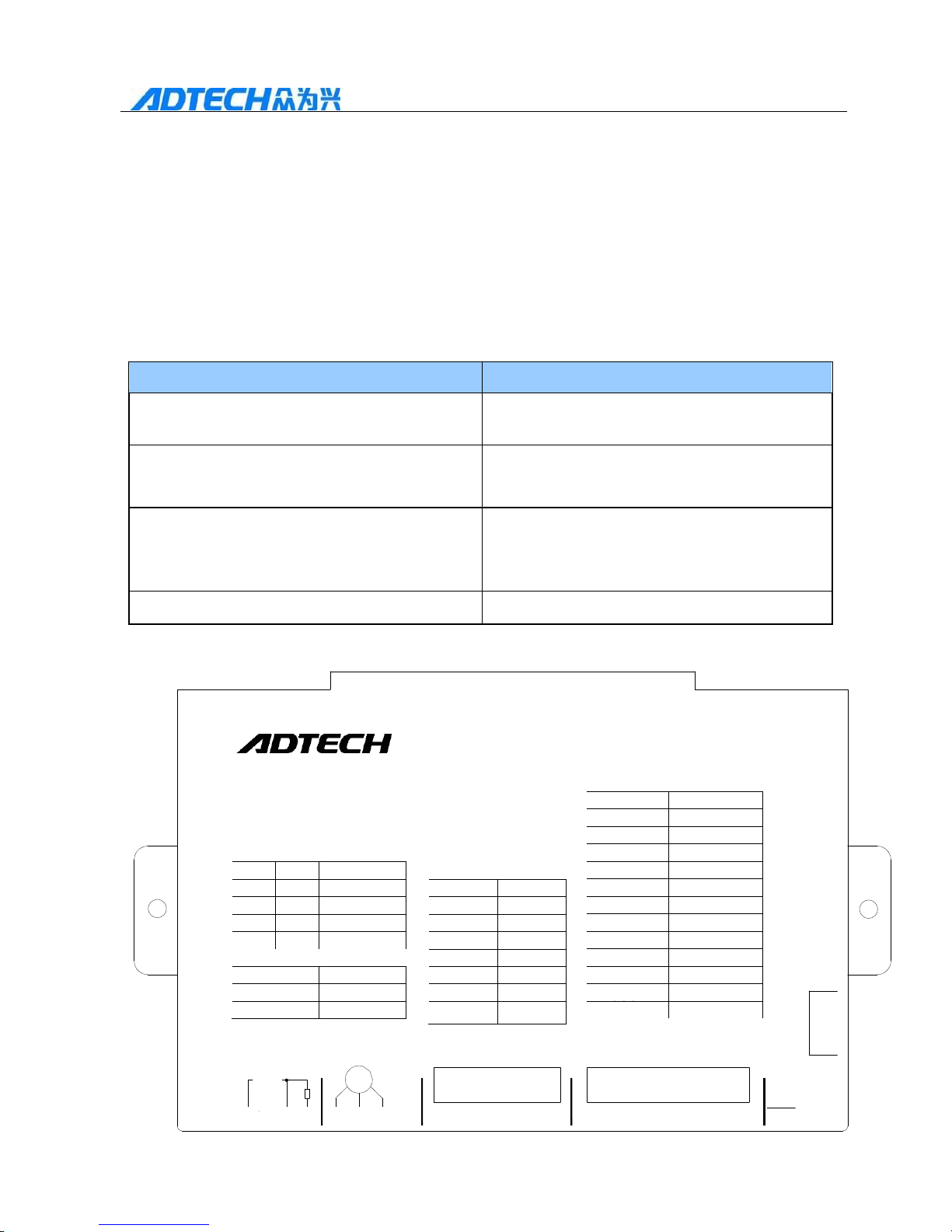
7
QS2 Series Low-voltage Servo Drive
1 PLUS-
14 CW
2 PLUS+
15 INCOM+
3 +5V DC
16 OUTCOM-
4 EN-
17 OB-
5 EN+
18 OB+
6 MODE
19 VIN-
7 ALRS
20 VIN+
8 OZ-
21 TIN+
9 OZ+
22 TIN-
10 SIGN+
23 ALM+
11 SIGN-
24 COIN+
12
25 OA-
13 CCW
26 OA+
SW1
SW2
OFF
OFF
P+D(100k)
OFF
ON
CC+CW
ON
OFF
A+B
ON
ON
P+D(500k)
1 A+
9 V+
2 B+
10 V-
3 GND
11 A-
4 W+
12 B-
5 U+
13 VCC
6 PE
14 W-
7 Z+
15 U-
8 Z-
SW3
SW4
OFF RS232
OFF 9600 bps
ON RS485
ON config
5
Chapter 1 Product Inspection and Information
1.1 Product Inspection
The product has passed functional and stability tests before delivery to
prevent any product malfunction due to negligence in delivery. Please check the
items below after opening.
Items
Reference Methods
Whether the model of the product is the same
as the ordered one?
Please check through the nameplate of the
servo motor and servo drive
Whether the rotation axis of servo motor
works well?
Rotate it by hands. But those with “brake
inside” cannot be rotated.
Whether there is something wrong with the
appearance and parts of the servo drive and
servo motor?
Please refer to the product standard
configuration; check if surface
damaged due to transport
Whether any screws loose?
Check them by screwdriver
If any malfunction is discovered in above items, please contact us or the
local distributor immediately. The nameplate is as shown as below:
AC servo drive
QS208020M
I/O:
COM1
Model select:
Encode:
COM2
24~80
VDC
M
10
1
9
6
18
SW4
SW3
SW2
SW1
1
10
15 11
26
19
Err
GND VCC BR
W v u
Run
I/O
PE
Encode
Page 8
8
QS2 Series Low-voltage Servo Drive
Input voltage
Drive capacity
Control method
80--DC 80V
020--20A
M—Positon,
speed and torque
control
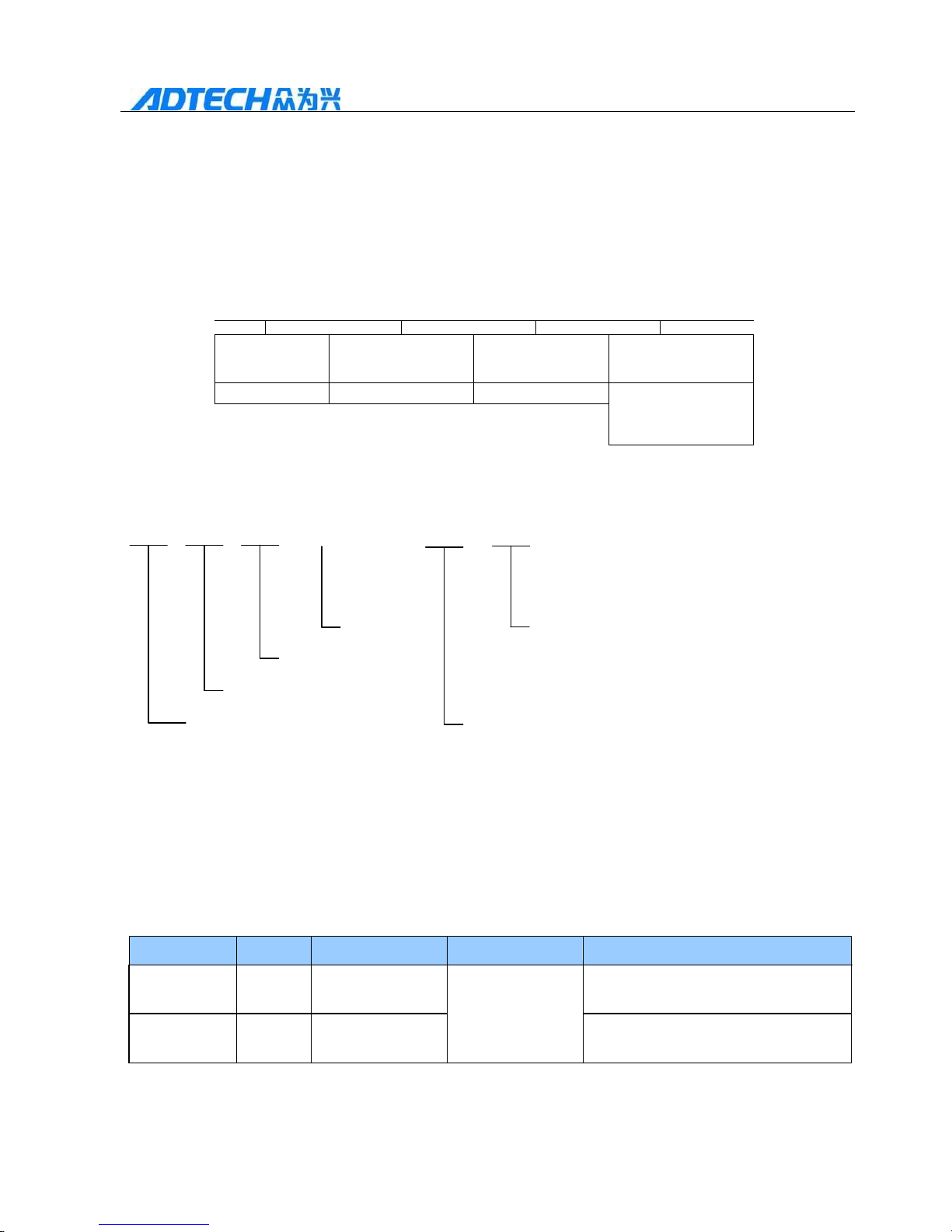
1.2 Naming Convention of Servo Motor and Drive
1.2.1 Naming convention of servo drive
QS2 08 020 M
1.2.2 Naming convention of servo motor
ACL 06 020 A —— 1 A
A: 11 Axis diameters
36V A=36 B: 14 Axis diameters
200W B=60
60 Flanges
1: 1000 wire encoder
Low voltage AC Servo 2: 2500 wire encoder
For example, ACL06020B-2B represents 60 flange, 200W, 60V, 2500 wire
encoder and 14mm axis diameter.
1.3 Reference Table for Servo Motor and Servo Drive
Configuration
Output power
Series
Servo motor
Servo drive
Motor rated torque and current
200W
ACL
ACL-06020B
QS208020M
60V voltage, 0.63NM,3000RPM
400W
ACL
ACL-06040B
60V voltage, 1.27NM,3000RPM
Page 9
9
QS2 Series Low-voltage Servo Drive
1.4 Features of QS2 Series Servo Drive
Power supply voltage from 24V to 80V with output current 6Arms;
Apply the advanced SVPWM algorithm;
Multiple pulse mode selection: pulse plus direction, pulse plus pulse and phase
A pulse plus phase B pulse;
Support RS-232 and RS485 communication;
High reliability: overvoltage protection, low voltage alarm, over current
protection and encoder alarm;
Special online debugging software;
Multiple selection of control method;
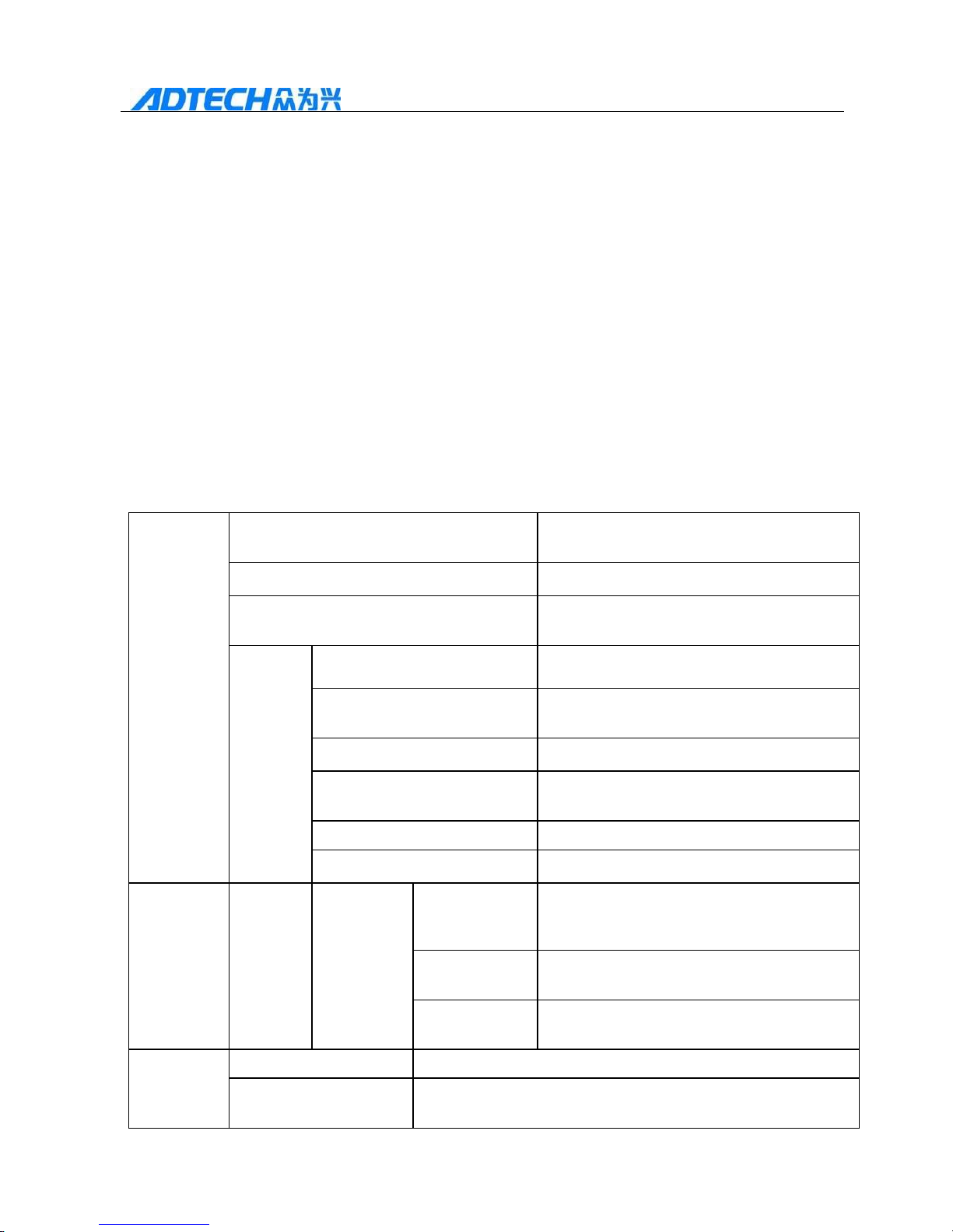
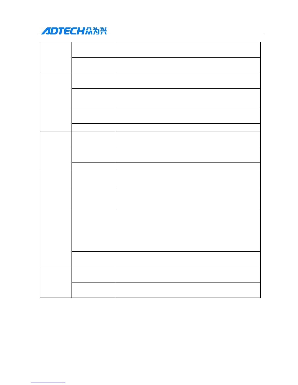
1.5 Technical Specifications of Servo Drive
Basic
specification
s
Control technology
Advanced FOC algorithm technology,
SCPWM space vector control
Input power supply
DC24V-80V
Feedback
Incremental 2500 wire photoelectric
revolving encoder
Conditions
of Use
Operating / storage
temperature
45℃/-20℃~55℃
Operating / storage humidity
40%~80%/0%~90% (no condensation)
Degree of protection
IP10
Resistance to vibration /
shock
4.9m/s2/19.6 m/s2
Altitude
<1000m, derate if above 1000m
Atmospheric pressure
86~106kpa
Position
Mode
Input
signal
Instruction
pulse
Pulse species
1. Pulse + direction
2. Pulse + pulse
3. A + B 90 ° quadrature pulse
Pulse shape
1. Differential drive
2. Open collector
Pulse frequency
1. Differential drive: 500K
2. Open collector: 200K
Speed
mode
Analog instruction input
-10V~10V, input impedance 10kΩ
Instruction acceleration
and deceleration
Parameter setting
Page 10
10
QS2 Series Low-voltage Servo Drive
Instruction
percentage
Parameter setting
Instruction source
External analog quantity, internal speed instruction
Torque
mode
Analog instruction
input
-10V~10V, input impedance 10kΩ
Instruction
acceleration and
deceleration
Parameter setting
Instruction
percentage
Parameter setting
Instruction source
External analog quantity, internal torque instruction
Input/outpu
t signal
Pulse output
signal
Differential output of A, B and Z phases of encoder
Input signal
Servo enable, alarm clearance, forward limit, reverse limit,
control method
Output signal
Position completion, servo alarm
Built-in
functions
Protection
function
Over current, overvoltage, under voltage, overload, encoder
exception and other alarms
Monitoring
functions
Rotation speed, current position, current pulse frequency,
position deviation, motor current, analog input value, etc.
Communication
functions
Achieve communication with PC via RS232 or RS485, and
achieve parameter modification and servo system running
status monitoring (RS232 and RS485 can’t be used
simultaneously. You can use DIP switch to select the
desired communication. For details see the Chapter 4.)
Indication
functions
Red (alarm), green (working) indicator
Other
features
Speed regulating
ratio
1:5000
Speed
fluctuation rate
<±0.03% (within rated load)
Page 11
11
QS2 Series Low-voltage Servo Drive
Chapter 2 Installation
2.1 Installation of stepper drive
2.1.1 Installation environment conditions
The environment for stepper drive installation has a direct impact on the normal
operation and life of the drive, so the drive installation environment must meet the
following requirements:
Operating environment: temperature: 0~45℃; humidity: 40%~80% (no
condensation);
Storage environment: temperature: -40~55℃; humidity: < 90% (no
condensation);
Vibration: < 0.5G;
Prevent raining and humid environment;
Avoid direct sunlight;
Prevent oil mist and salt erosion;
Keep away from corrosive liquid and gas;
Prevent dust, cotton, and small metal filings;
Keep away from radioactive and flammable objects;
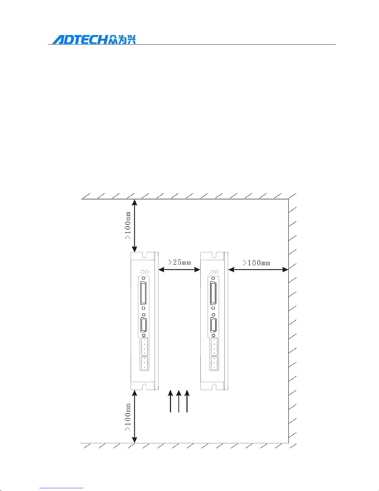
When several drives are installed in the control cabinet, retain sufficient space
to help the flow of air; to help cooling, please install a fan to reduce the
temperature around the drive; to ensure long-term safety, the operating
temperature should be 45℃;
If there is unavoidable vibration source nearby, use vibration absorber or install
anti-vibration pad to avoid transmitting the vibration to the servo drive;
When interference is mixed in power supply circuit of input signal, it is easy to
cause drive malfunction. If interference may be mixed, take appropriate
measures, such as adding a noise filter and a variety of other anti-jamming
measures, to ensure the normal operation of the drive. (Note that the leakage
current will increase if noise filter is added. In order to avoid this situation, you
can use an isolation transformer. The control signal lines of the drive are
susceptible to interference, and reasonable alignment and shielding are
required.)
Page 12
12
QS2 Series Low-voltage Servo Drive
2.1.2 Installation method and size
Mounting direction: Normal mounting direction of the stepper drive is vertical
or horizontal;
Mounting and fixing: Use two vertical mounting holes, four horizontal
mounting holes and tighten with screws;
Ventilation: use natural cooling; cooling fan must be installed in the
electrical control cabinet.
Installation sizes for multi-drive machine are as shown in the figure below:
unit (mm)
Ventilation direction
Page 13
13
QS2 Series Low-voltage Servo Drive
1 PLUS+
14 CW
2 PLUS-
15 INCOM+
3 +5V DC
16 OUTCOM-
4 EN-
17 OB-
5 EN+
18 OB+
6 MODE
19 VIN-
7 ALRS
20 VIN+
8 OZ-
21 TIN+
9 OZ+
22 TIN-
10 SIGN+
23 ALM+
11 SIGN-
24 COIN+
12 PLCCOM+
25 OA-
13 CCW 26 OA+
SW1 SW2
OFF
OFF
P+D(100k)
OFF ON
CC+CW
ON
OFF
A+B
ON ON
P+D(500k)
1 A+ 9 V+
2 B+
10 V-
3 GND
11 A-
4 W+
12 B-
5 U+
13 VCC
6 PE
14 W-
7 Z+
15 U-
8 Z- SW3 SW4
OFF RS232
OFF 9600 bps
ON RS485
ON config
5
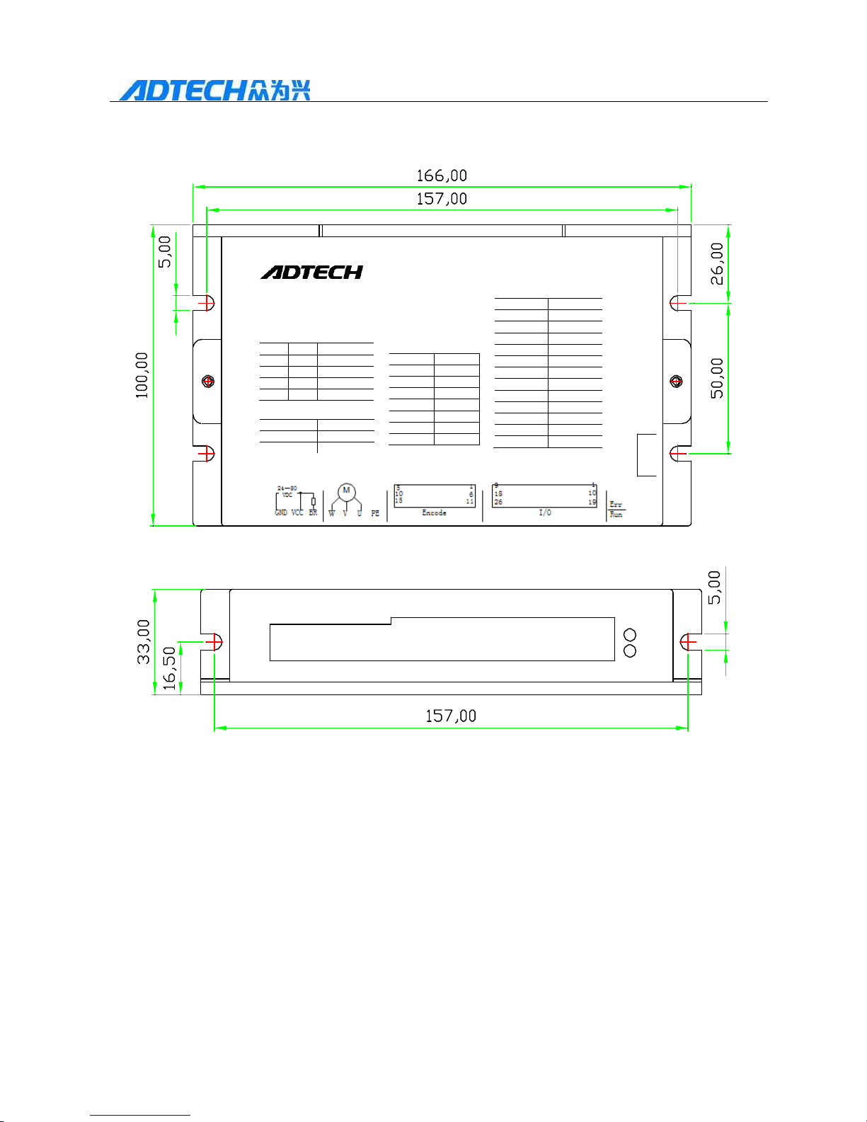
Drive size: unit (mm)
AC servo drive
QS208020M
I/O:
COM1
Modle select:
Encode:
COM2
SW4
SW3
SW2
SW1
24~80
VDC
M
10
1
9
15
11
26
GND VCC BR
Encode
2.2 Installation of servo motor
2.2.1 Environmental conditions of installation
Operating environment: temperature: 0~45℃; humidity: 40%~80% (no
condensation);
Storage environment: temperature: -40~55℃; humidity: < 80% (no
condensation);
Vibration: < 0.5G,
Prevent raining, humid and oil fouling environment;
Avoid direct sunlight;
Prevent dust, cotton, and small metal filings.
Page 14
14
QS2 Series Low-voltage Servo Drive
Notes for installation:
Do not knock on motor or motor axis when disassemble chain wheels, to
prevent the encoder being damaged. Screw type pressing and pulling tools shall
be used for disassembly;
The motor cannot tolerate large axial radial load. It is recommended to be
loaded with flexible coupling;
Motor shall be secured with nut-lock washer to prevent motor loosening;
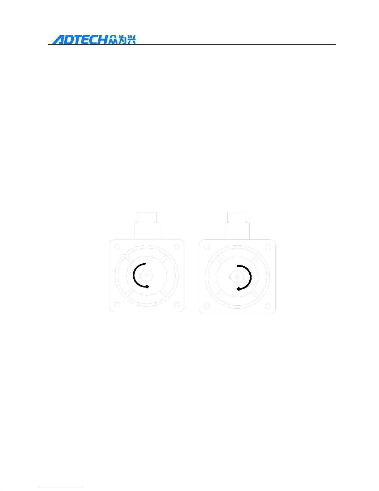
2.2.2 Definition of Motor Rotation Direction
Facing to the motor shaft extension, forward is to rotate counterclockwise
direction, and reverse is to rotate in clockwise direction. The direction of the
motor in the drive can change internal parameters P16 of the drive and change
direction according to the actual situation.
Forward rotation Reverse
Counter-clockwise (CCW) Clockwise (CW)
Page 15
15
QS2 Series Low-voltage Servo Drive
Chapter 3 Wiring
3.1 Overall Wiring Diagram
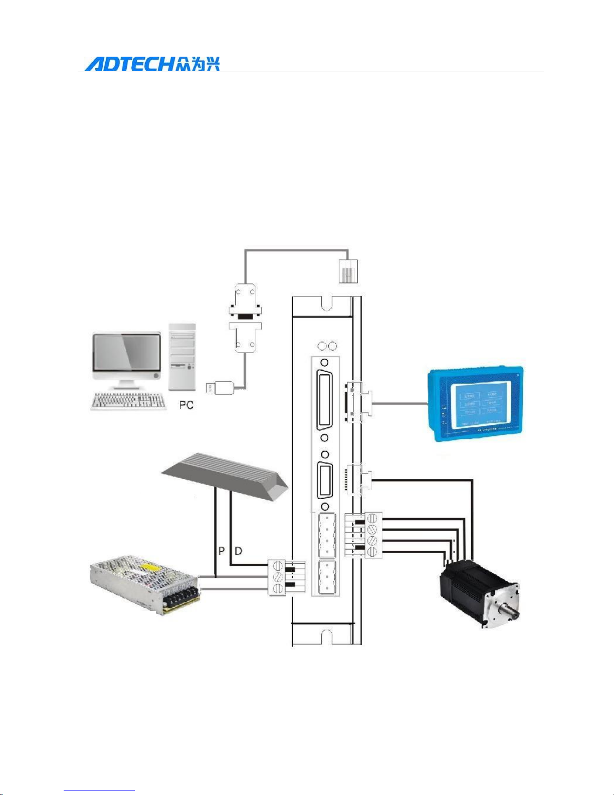
1. Overall wiring diagram of QS2 Series is as shown in the figure
below:
Communication
wire
Control
wire
Brake
resistance
Switching mode
Power supply
Page 16
16
QS2 Series Low Voltage Servo Drive
2. Explanation of wire specification
Motor model
Requirement on wire diameter
Main power
Motor power cable
Encoder and control signal wire
200W
1.25mm
2
1.25mm
2
0.14mm
2
Page 17
17
QS2 Series Low Voltage Servo Drive
400W
1.25mm
2
1.25mm
2
0.14mm
2
3. Wiring requirement
The wiring material shall be in accordance with the wiring specification;
As for cable length, the instruction cable shall be less than 3m and the encoder
cable shall be within 10m;
Check if the wiring between the drive and power is correct. Do not connect
with the power more than DC 80V;
U, V, W terminals of motor must be matched correspondingly. The wrong
wiring may cause no rotation or motorcycling;
The wiring must be reliable with single-point grounding;
Please position the power cable (strong electricity circuit such as power wire,
motor wire) over 30cm away from the signal wire. Do not put the two wires in
the same conduits;
Please install the non-fusion circuit breaker so that the external power supply
can be cut off when the drive fails.
3.2 Port name and function
3.2.1. Introduction of interface
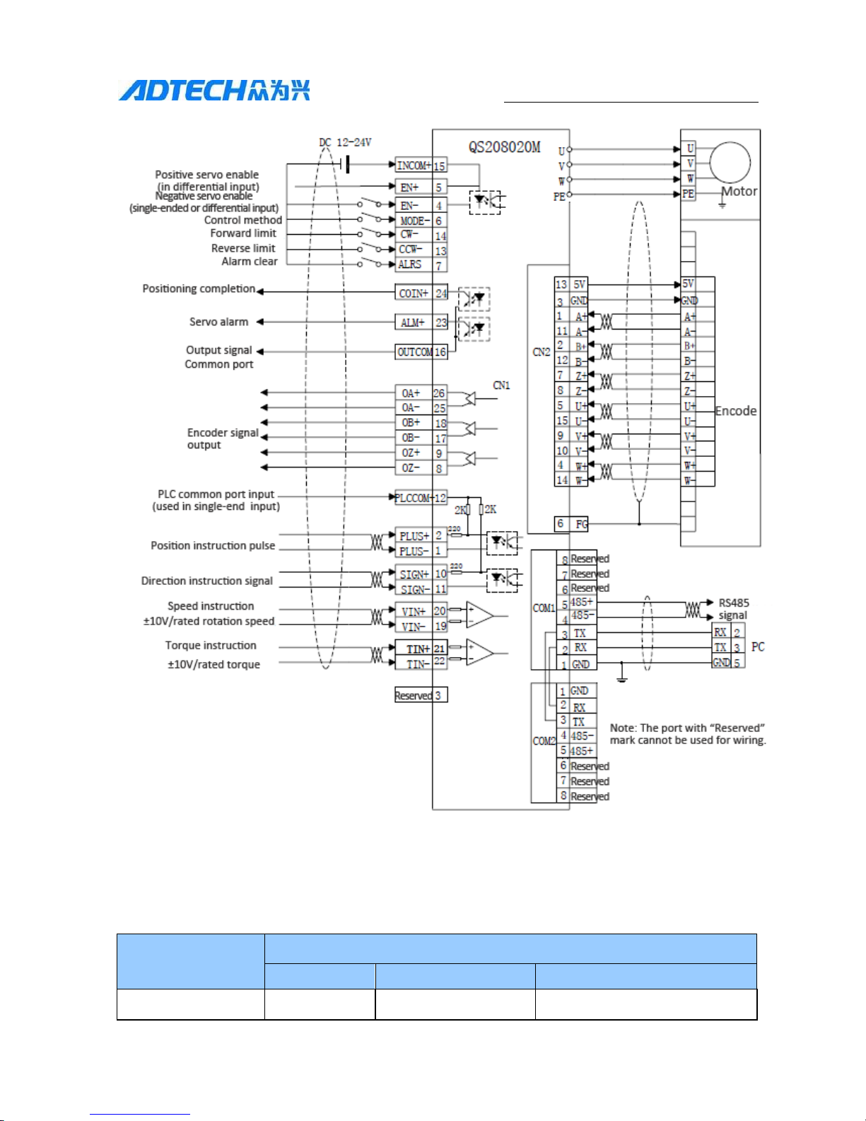
QS2 series low voltage servo drive. The external wiring terminals are mainly as
follows:
Terminal Code
Terminal name
Description
GND, VDC,
BR
Main power input
Main power input for drive
U, V, W, PE
Motor power cable
Supply current with the motor
CN1
Controller signal wire
terminal
Used to connect upper computer (controller, PLC)
CN2
Encoder terminal
Feedback signal of encoder
COM1, COM2
Communication
terminal
Used to communicate with PC
Page 18
18
QS2 Series Low Voltage Servo Drive
3.2.2. Details on Interface
(1)Power terminal
No.
Code
Signal function
1
GND
Power grounding
2
VDC
Main power input 24~80VDC
3
BR
Connecting pin for brake resistance (the brake
resistance is connected between VDC and BR)
(2)Terminal of motor power cable
No.
Code
Color
Signal function
1
W
Black
Motor UVW
2
V
Green
3
U
Red
4
PE
Yellow
Connected with motor housing
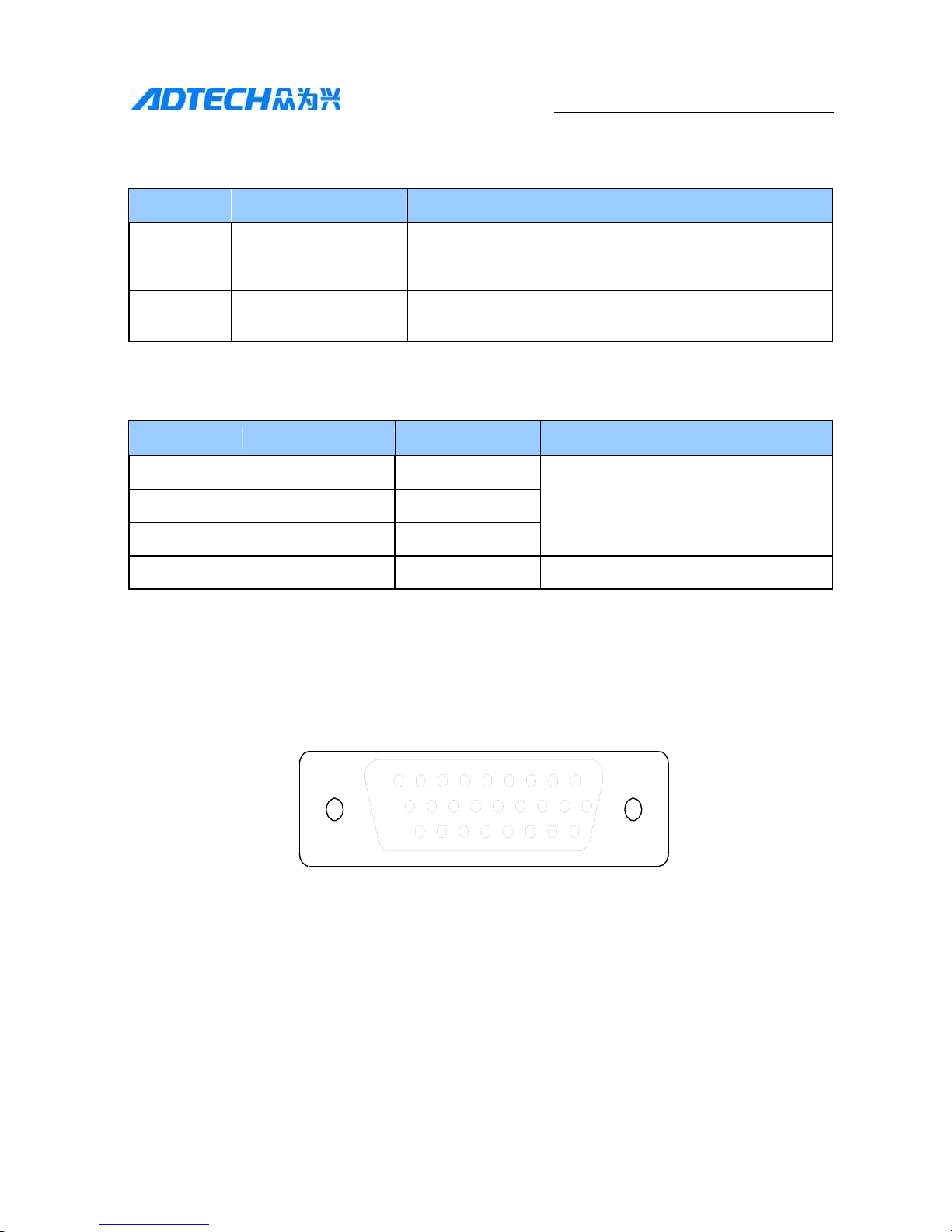
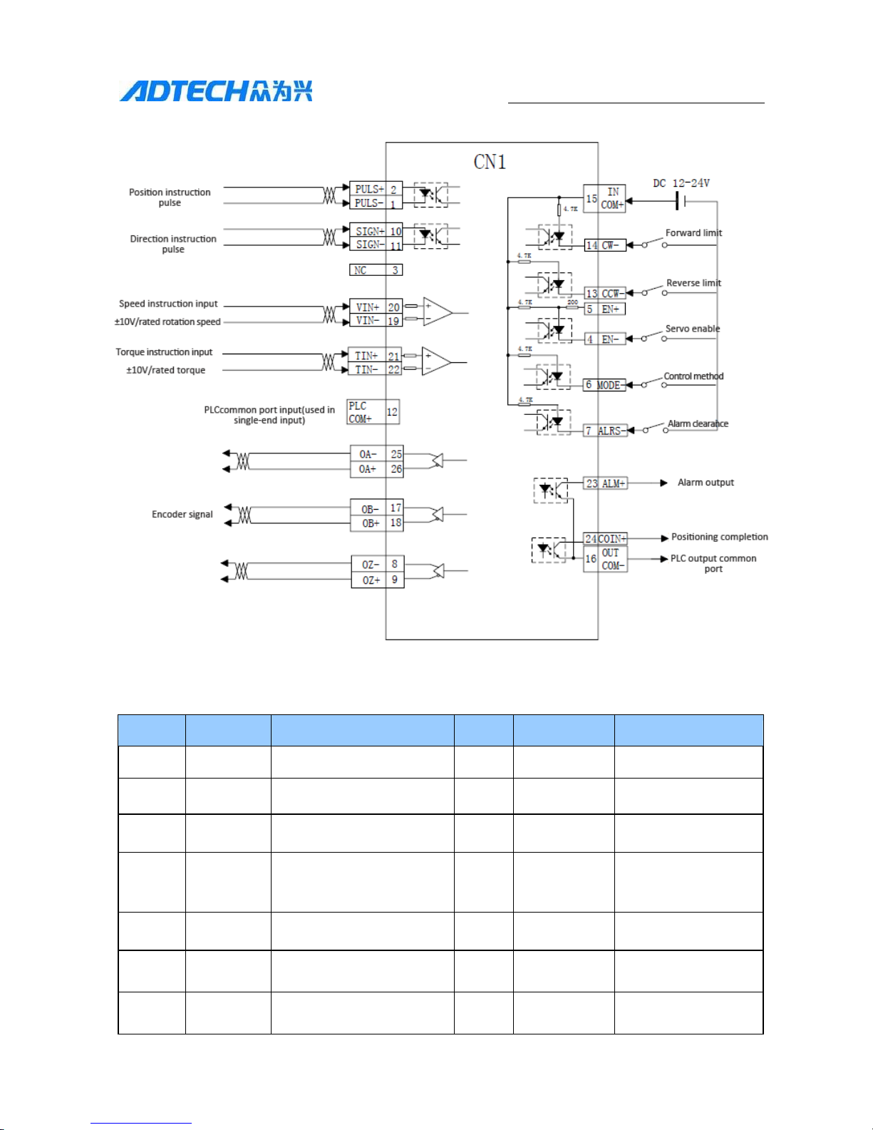
(3)Terminal of CN1 controller signal wire: the board terminal CN1 is the socket
component for DB26 on the receptacle.
QS2 series low voltage servo drive controller signal wire terminals are as
follows:
9
1
18
10
26
19
Note: From the side of bonding wire
Page 19
19
QS2 Series Low Voltage Servo Drive
CN1 internal structure drawing
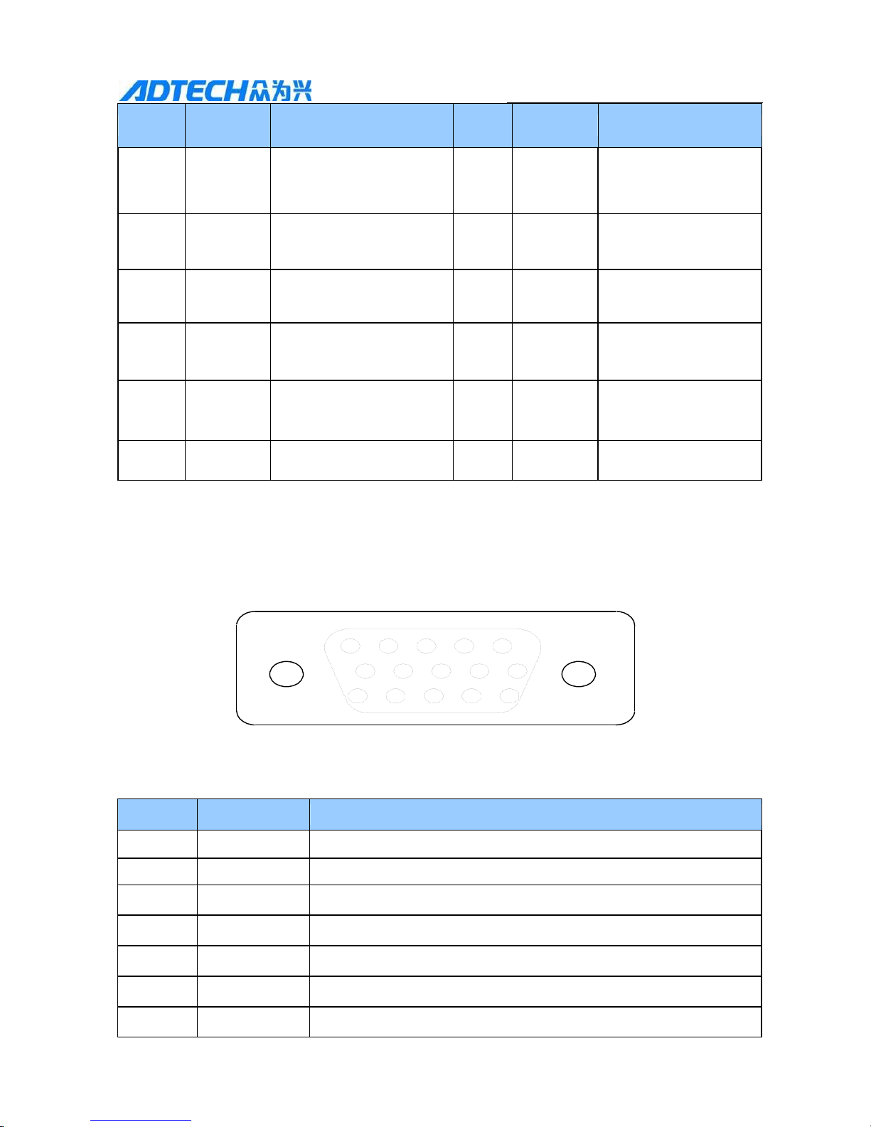
Details on CN1 terminal:
Pin No.
Code
Description
Pin No.
Code
Description
1
PLUS-
Negative pulse signal
14
CW
forward limit
2
PLUS+
Positive pulse signal
15
INCOM+
Power positive
3
NC
NC, reserved
16
OUTCOM-
Common port of
output signal
4
EN-
Negative input of enable
(single-end/differential
input)
17
OB-
Encoder B-
Positive input of enable
(differential input)
18
OB+
Encoder B+
6
MODE
Control method or mode
selection
19
VIN-
Speed analog input
negative
7
ALRS
Alarm clearance
20
VIN+
Speed analog input
positive
Page 20
20
QS2 Series Low Voltage Servo Drive
Pin No.
Code
Description
Pin No.
Code
Description
8
OZ-
Negative signal of
encoder Z
21
TIN+
Positive torque analog
input
9
OZ+
Negative signal of
encoder Z
22
TIN-
Negative torque
analog input
10
SIGN+
Positive direction signal
23
ALM+
Servo alarm+
11
SIGN-
Negative direction signal
24
COIN+
Positioning
completion+
12
PLCCO
M+
PLC 24V input(used in
single-end input)
25
OA-
Encoder A-
13
CCW
Reverse limit
26
OA+
Encoder A+
(4) Encoder feedback signal terminal: The board terminal CN2 is the socket
component for DB15 on the receptacle.
QS2 series low-voltage servo drive encoder feedback signal wire terminals are
as follows:
5 1
10
6
15
11
Note: Seen from the side of bonding wire
Pin No.
Code
Signal function
1
A+
Positive signal input of motor encoder A
2
B+
Positive signal input of motor encoder B
3
GND
Input power supply GND
4
W+
W+ signal input
5
U+
U+ signal input
6
FG
Shielding grounding
7
Z+
Encoder Z+ signal input
Page 21
21
QS2 Series Low Voltage Servo Drive
Pin No.
Code
Signal function
8
Z-
Encoder Z- signal input
9
V+
V+ signal input
1
V-
V- signal input
11
A-
Encoder A- signal input
12
B-
Encoder B- signal input
13
VCC
5V
14
W-
W- signal input
15
U-
U- signal input
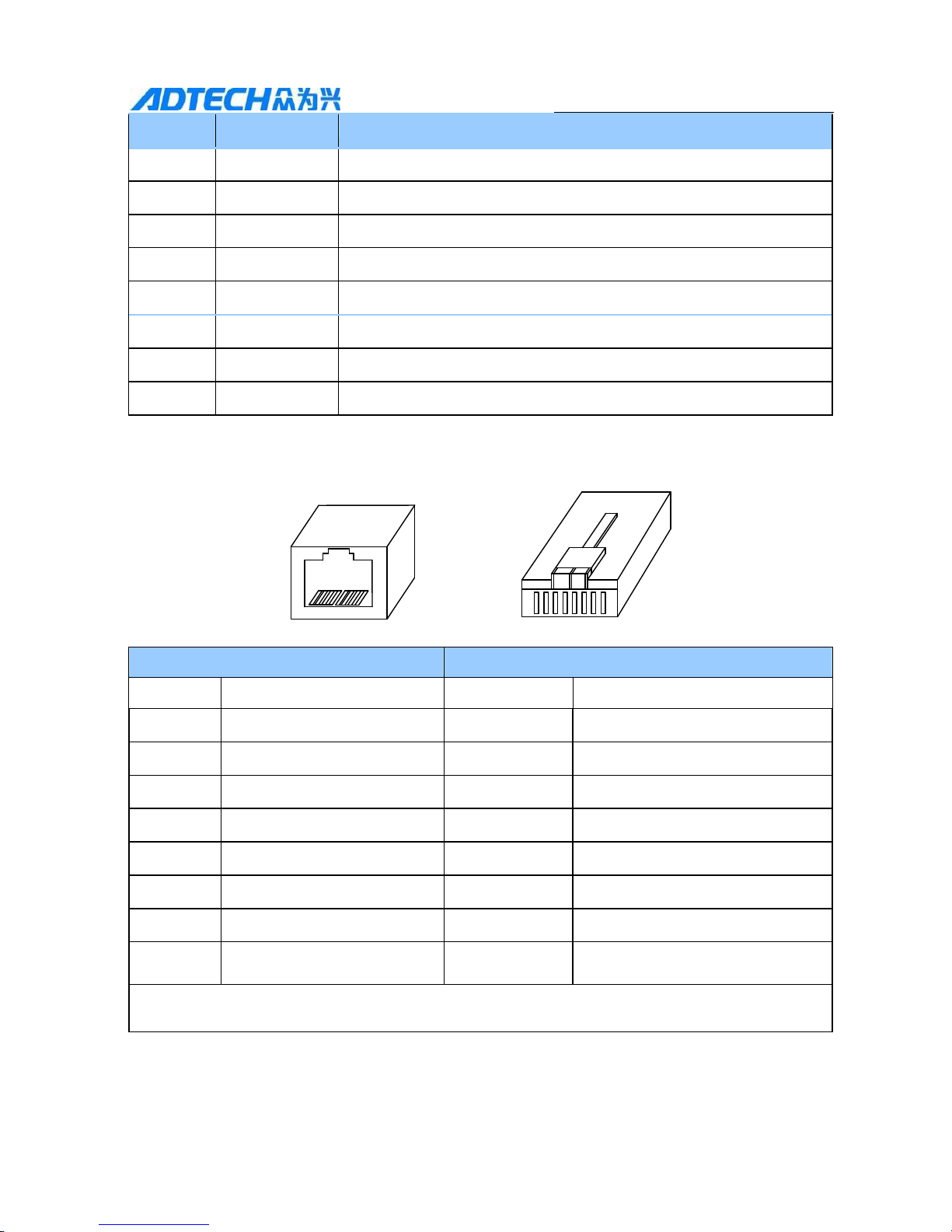
(5) Communication interface COM1, COM2
Port base
Connector
COM1
COM2
Pin No.
Signal name
Pin No.
Signal name
1
GND
1
GND
2
RXD
2
RXD
3
TXD
3
TXD
4
RS485-
4
RS485-
5
RS485+
5
RS485+
6
VCC
6
VCC
7
Reserved
7
Reserved
8
For manufacturer’s special
purpose
8
For manufacturer’s special
purpose
Not: Conduction of COM1 and COM2 would meet the RS485 multi-point communication
under the multiple axial conditions.
1 3
Page 22
22
QS2 Series Low Voltage Servo Drive
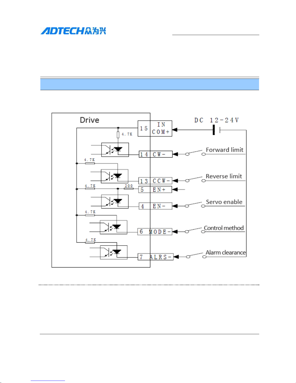
3.3 Principle of Input and Output Interface
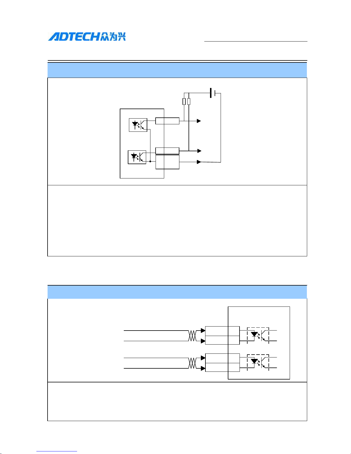
3.3.1 Switch EN-, MODE-, CW-, CCW-, ALRS-input interface
Switch EN-, MODE-, CW-, CCW-, ALRS-input interface
1. DC 12V-24V
2. Current is less than 20mA
3. Polarity reverse of power supply will cause servo drive damage.
4. Inductive load must be connected with fly-wheel diode at its two loaded ends in a paralleling
way.
Page 23
23
QS2 Series Low Voltage Servo Drive
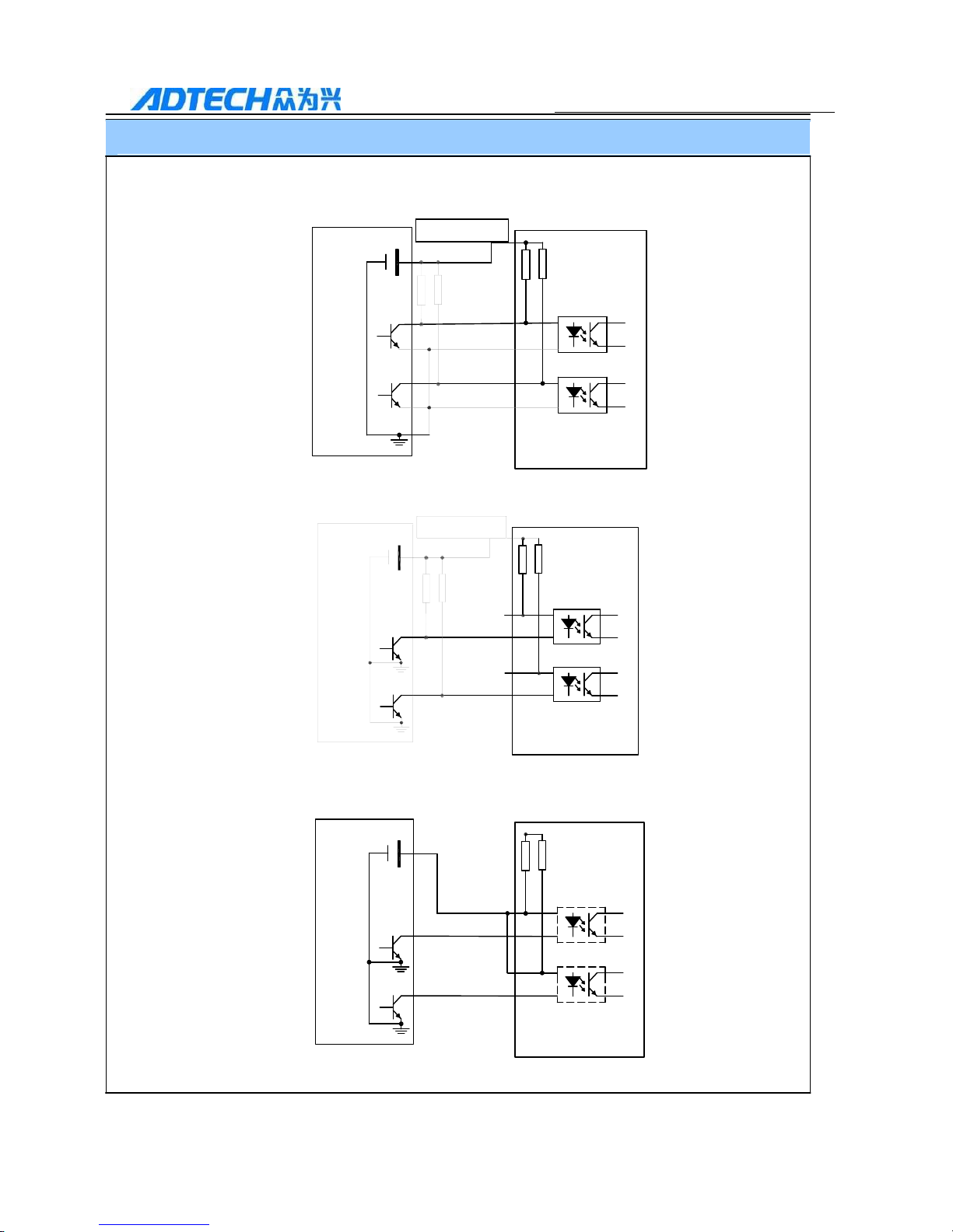
3.3.2 Switching value ALM, COIN output interface
Switch ALM, COIN output interface
Pull-up
Resistor drive
23 ALM+ Alarm output
24
COIN+ Positioning completion
16
OUT
PLC output common port
COM-
1. Power supplied by user is 12V~24VDC. The maximum signal output current is 20mA.
2. The output is in a form of open collector. The pull-up resistor shall be selected according to
the user’s system. The empiric value:
VCC=12V, R=1K, 1/4W is recommended
VCC=24V, R=2K, 1/4W is recommended
3. Inverse connection of power supply would damage the servo drive.
3.3.3 Pulse signal input interface
Differential input of pulse signal
Drive
Position instruction pulse PULS +2
PULS -1
Direction instruction pulse
SIGN +10
SIGN - 11
1. Pulse frequency≤500KHz, duty ratio is 1:1, and the actually required is 0.4us。
2. It is recommended to use differential drive mode
3. Apply AM26LS31, MC3487 or the similar RS422 wire drive
Page 24
24
QS2 Series Low Voltage Servo Drive
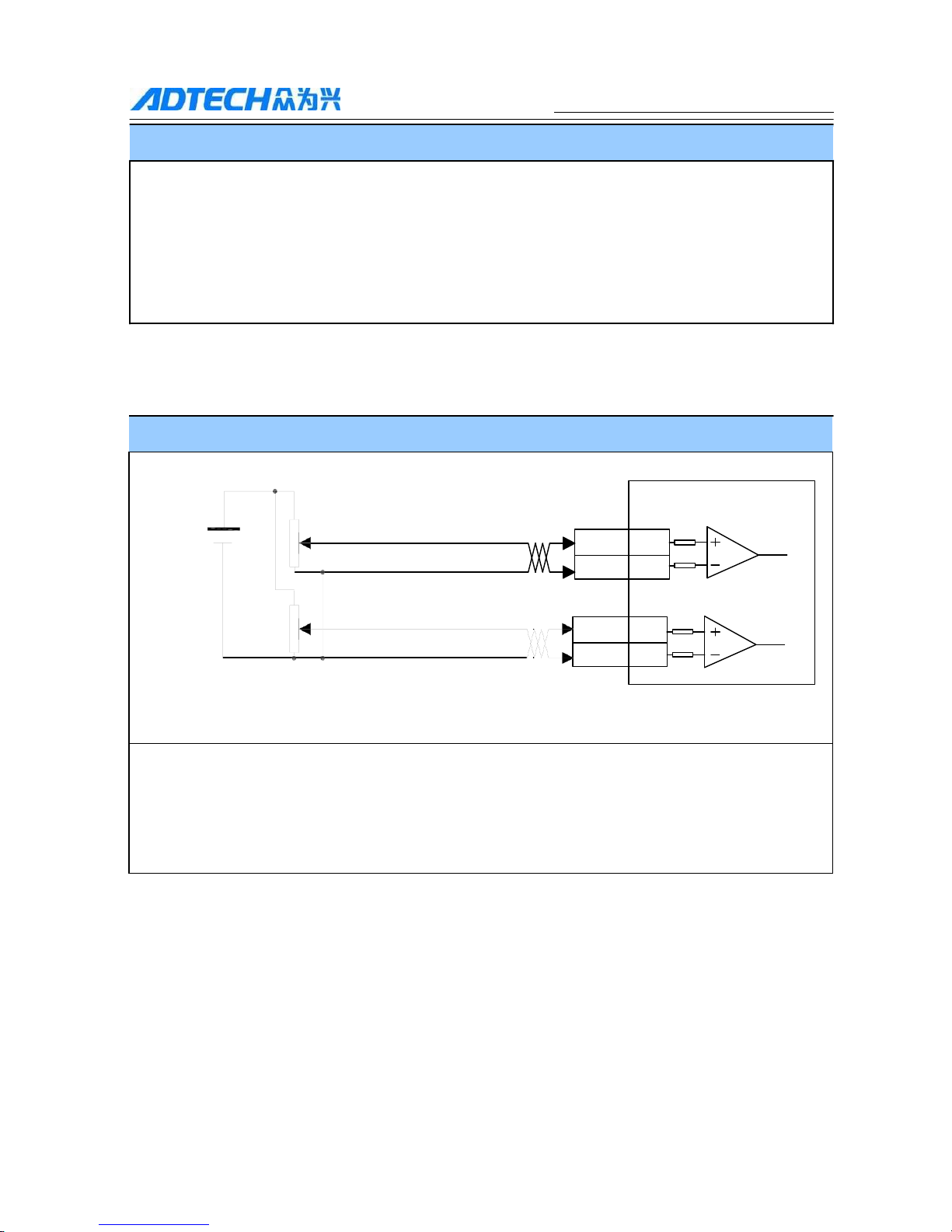
Single-end input of pulse signal (applicable to upper computer like PLC)
1. 24V single-end common cathode input connection:
Upper
comp
uter
PLC
24
V
INPLCCOM
+
12
2K
PULS+
PULS-
2K
Drive
SIGN+
SIGN-
2. 24V single-end common anode input connection
Upper
comp
uter
PLC
24
V
INPLCCOM+
12
2K
PULS+
PULS-
2K Drive
3. 5V single-end common anode input connection:
5V
2K
Drive
Upper computer
PULS
+
PULS-
SIGN+
SIGN-
SIGN+
SIGN-
Page 25
25
QS2 Series Low Voltage Servo Drive
Single-end input of pulse signal (applicable to upper computer like PLC)
● Generally used in PLC pulse control
● Drive current is 10~15mA.
● Do not connect the polarity of power supply in a wrong direction.
● Pulse frequency of the connection ≤200KHz。
● The connection shall be demonstrated with the Mitsubishi PLC wiring cases and the
company’s wiring cases
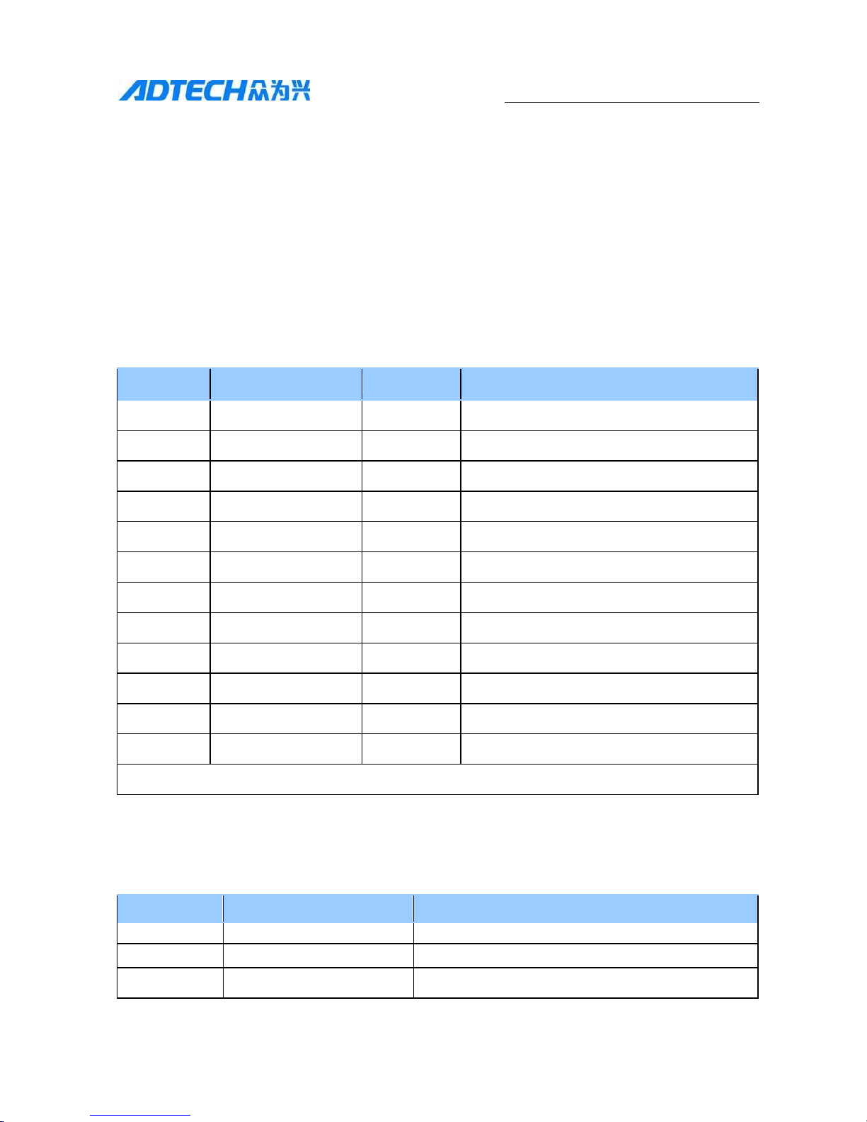
3.3.4 Analog Quantity input interface
Input of speed analog quantity and torque analog quantity
±10V
Speed instruction input
Drive
±10V/rated rotation speed
Torque instruction input
±10V/rated torque
1. Speed instruction input: positive /reverse speed limited by external analog quantity voltage.
2. Torque instruction input: positive/reverse speed limited by external analog quantity voltage.
3. Input voltage scope is -10V~+10V.
4. Input impedance: about 10KΩ
VIN +19
VIN -20
TIN +21
TIN -22
Page 26
26
QS2 Series Low Voltage Servo Drive
Chapter 4 LED Alarm Indicators and Dial
Switch
4.1 LED Indicator Light
4.1.1 Red LED
Red indicator light is alarm indicator light. It is out in normal system. Its
flicker frequency is the code delegating the following status:
No.
Flicker frequency
Alarm code
Description of fault
1 1 1
Encoder alarm
2 2 2
Single phase over current
3 3 3
Overload alarm
4 4 4
Overvoltage of hardware
5 5 5
Over current of hardware
6 6 6
Overvoltage of software
7 7 7
Limit alarm
8 8 8
Reserved by manufacturer
9 8 9
Position deviation alarm
10 8 16
Reserved by manufacturer
11
Constantly on
--
System fault
12
Constantly out
--
Normal
Note: Alarm code is readable from the upper computer’s interface
4.1.2 Green LED
The green indicator indicates the servo enable signal and its indicator contents
are as follows:
No.
Current status
Description
Flicker
Drive power supply is in normal condition
2
Constantly on
Motor servo enable
3
Constantly out
Power supply fault
Page 27
27
QS2 Series Low Voltage Servo Drive
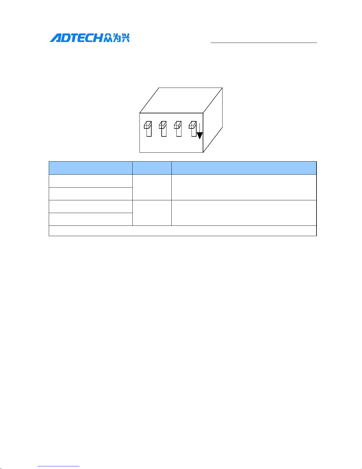
4.2 DIP Switch
QS2 series dial switch is as follows:
OF
F
SW1 SW2 SW3 SW4 ON
SW1
SW2
SW3
SW4
00=P+D
100khz
0=RS232
0= 9600bps in default, communication station No.1
01=CCW+CW 100khz
10=A+B
100khz
1=RS485
1=custom, related with the drive internal parameters
11= P+D 500Khz
Note: 0= OFF, 1= ON
Note 1: Switch1 and 2 are for the selection of pulse mode, Switch 3 is for the selection of
communication mode, and Switch 4 is for the selection of communication baud rate and
communication station number. For details, please refer to Chapter 5.
Note 2: When the baud rate and communication mode needs changing, the drive shall be
electrified again.
Note 3: When SW1 SW2=00, only the PLC frequency and the pulse within 100KHZ can be
received; and when SW1 SW2=11, both PLC frequency and the pulse within 500KHZ can be
received.
Page 28
28
QS2 Series Low Voltage Servo Drive
Chapter 4 Drive and Computer
Communications
QS2 servo drives can communicate with other devices via RS232 or RS485. The
communication mode can be set via DIP switch. RS communication can
communicate with the computer self-contained series port. Because of the
convenience of USB-RS232/485, we will explain with it.
5.1 Installing USB-RS485/RS232 Drive
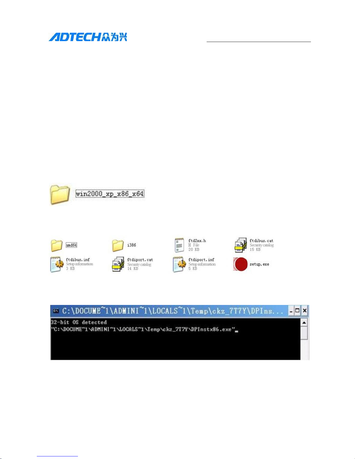
Insert the drive CD into the CD-ROM, and click on the CD-ROM to show the
following folder (Below is the example of Windows XP/2000)
Click to enter
Click the executable file "setup.exe" to show the following installation window;
Wait for the installation to complete. View the communication port of the computer
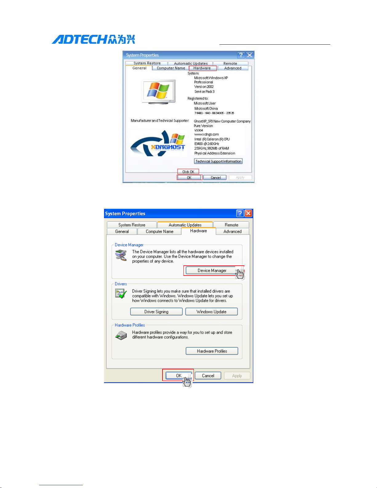
allocated for this drive. Right click My Computer and select "Properties" menu to
pop up the window.
Page 29
29
QS2 Series Low Voltage Servo Drive
Click OK to pop up the window, select Hardware - Device Manager, and click OK;
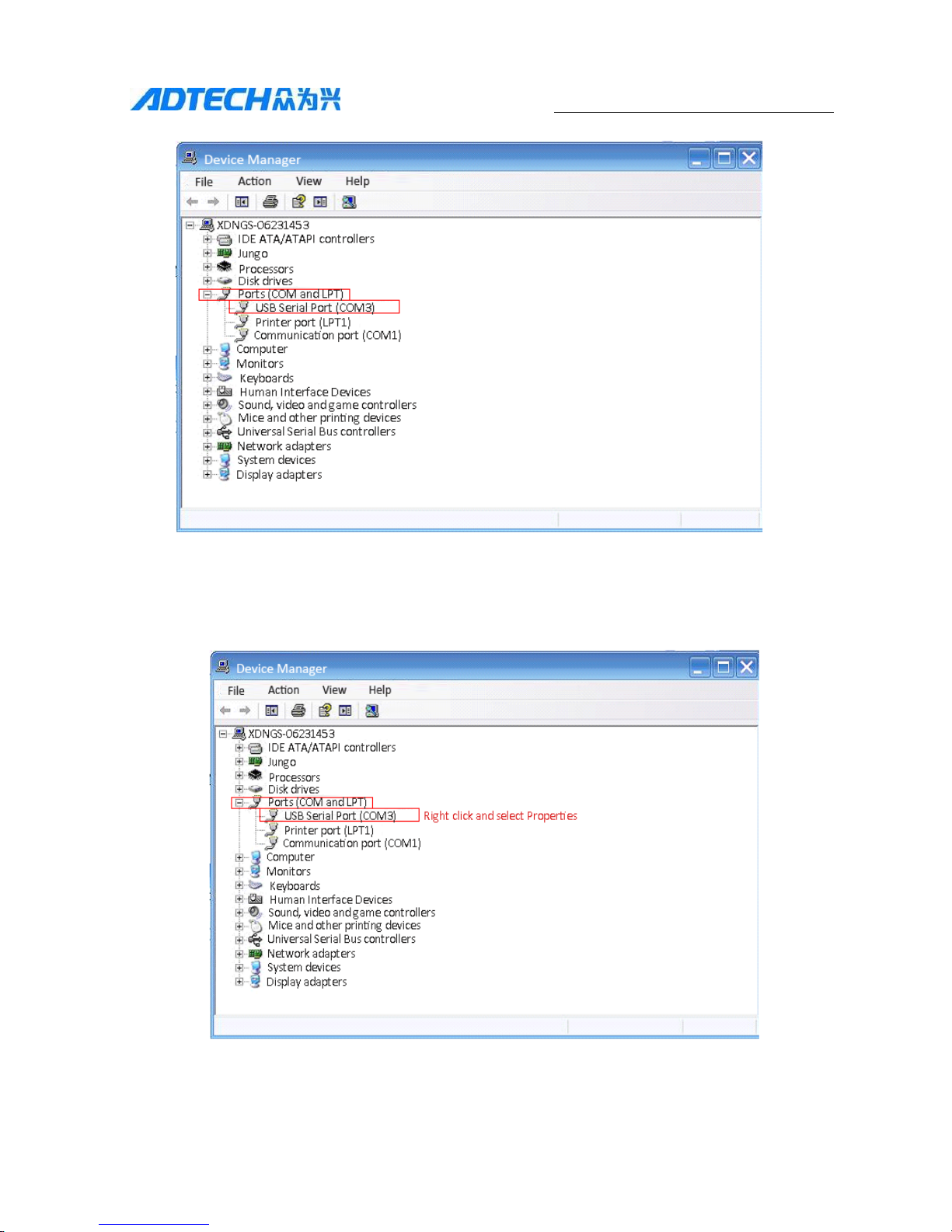
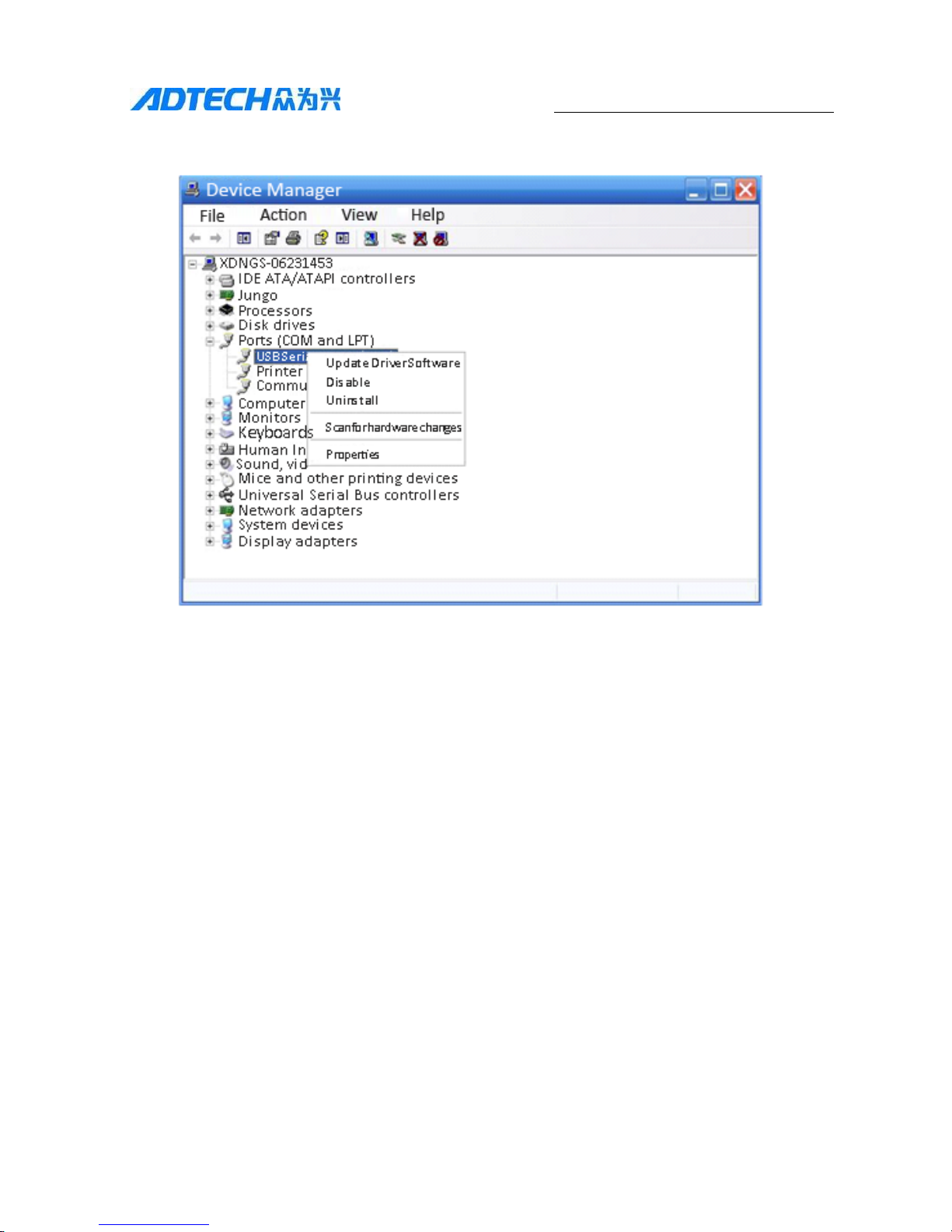
Click Ports (COM & LPT) to view the COM port of the computer allocated for the
drive, write down the COM number, and use to connect parameter management
software.
Page 30
30
QS2 Series Low Voltage Servo Drive
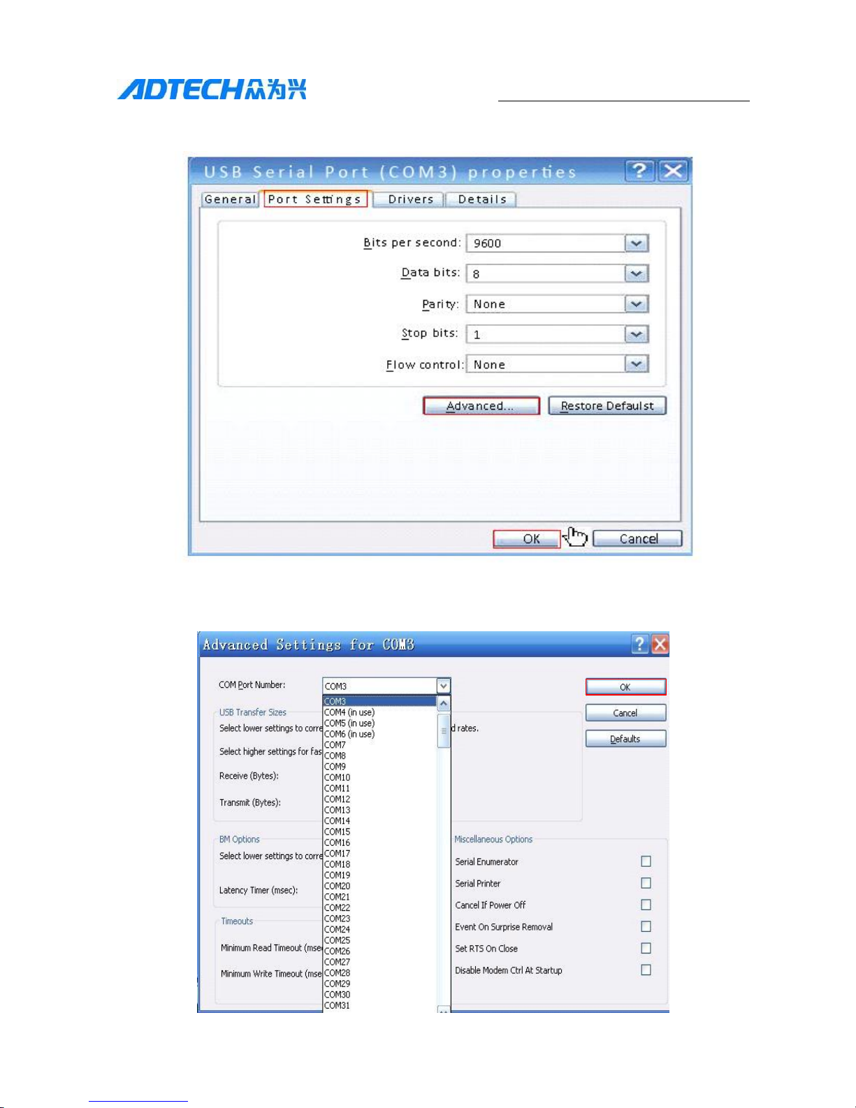
If the COM isn’t between COM1-COM6, please change as follows:
右键点击,选择“属性”
Page 31
31
QS2 Series Low Voltage Servo Drive
In the pop-up dialog box, select the "Port Settings" - "Advanced" and click OK;
In the pop-up window, select a COM port within 1-6, and click OK, step by step;
Page 32
32
QS2 Series Low Voltage Servo Drive
Return to the screen, right-click "Ports (COM & LPT)", and select "Scan for
hardware changes";
After scanning, write down the changed COM port and use to connect the
software.
5.2 Open the drive software, and set parameters
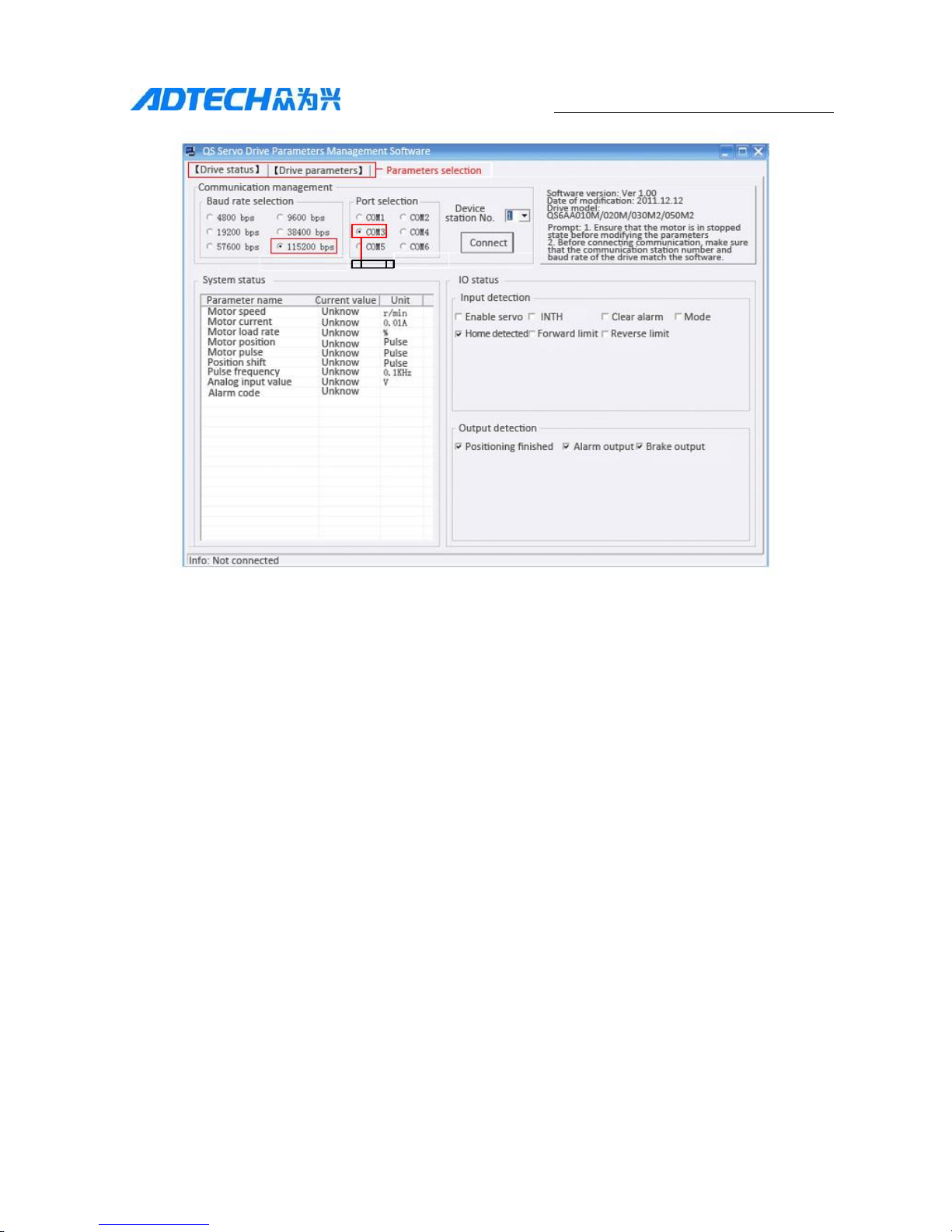
(1) The communication baud rate and the communication baud rate in the drive can
be set by dial switch. The baud rate of parameter management software is
selected according to the setting of the drive.
(2) The communication interface shall be set as the computer integrated port COM1
and other ports shall be known through above steps;
Page 33
33
QS2 Series Low Voltage Servo Drive
通讯端口
Communication baud rate selection
It shall be set as 1 in default in communication station number parameter
management software and the drive. “Connect” the motor to communicate after
setting of the communication parameters.
5.3 Parameter settings
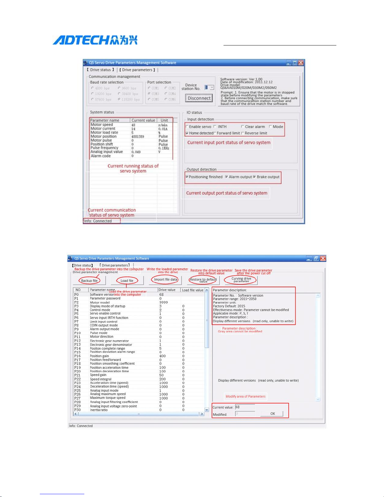
(1) After connecting the communication successfully, the basic state of the motor
running is displayed on the drive status screen; you can check if the machine has
failure according to the status of the servo system running; the interface is as
follows;
Communication interface
Communication interface
Page 34
34
QS2 Series Low Voltage Servo Drive
将加载进来的参数
暂时写入驱动器中
将驱动器的参数恢
复成出厂值
将驱动器中的参数
值实现断电保存
(2) Click "Drive Parameters" and enter the parameter modification interface;
将驱动参数备份到计算机
将驱动参数加载到
参数管理软件中
参数说明,灰色 的
是不可修改的
参数修改区域
Page 35
35
QS2 Series Low Voltage Servo Drive
5.4 Custom Baud Rate
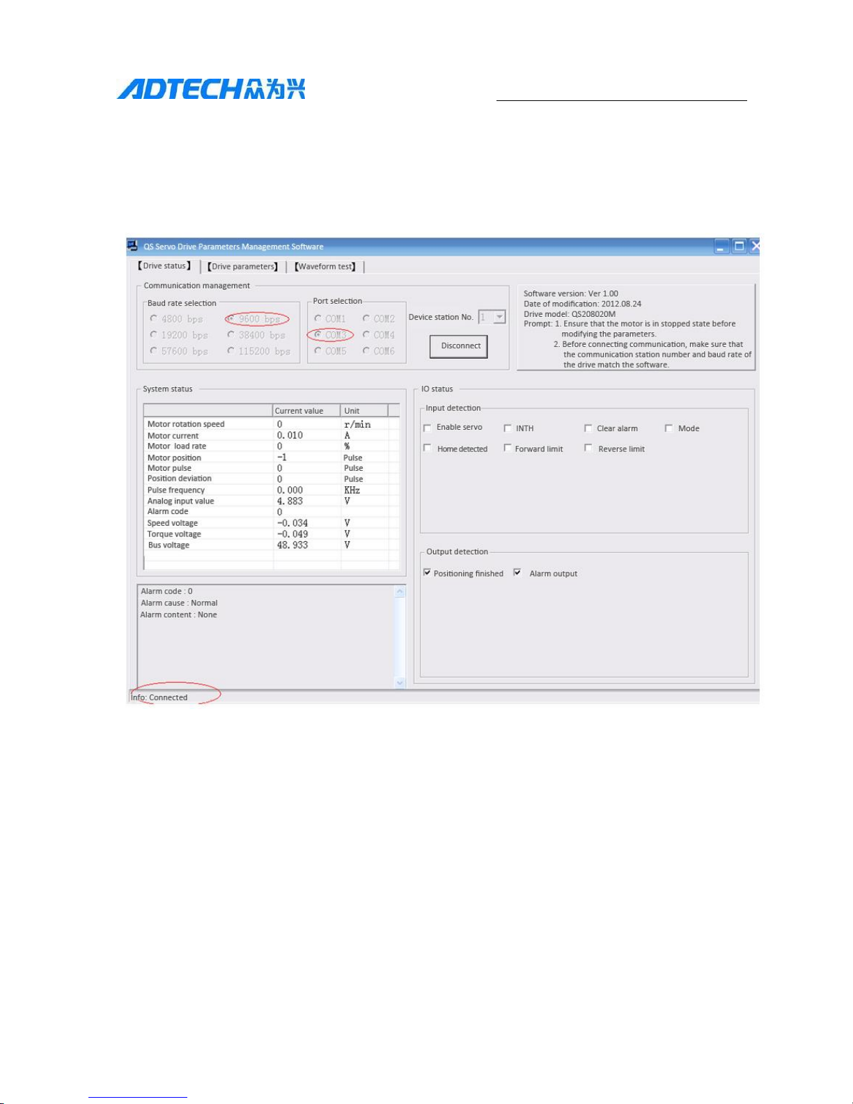
If you want to use custom baud rate, change the parameter P44. Below is the example
of the steps to change the baud rate of the drive from 9600 to 115200:
(1) The baud rate is 9600, port is COM3, communication is RS232, and
communication connection is OK.
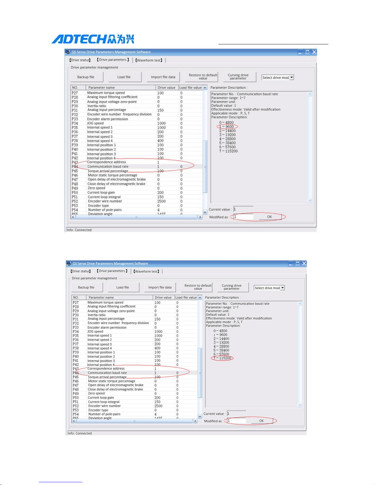
(2) At this time, you can see P44 = 1 in P44 parameter "communication baud rate";
to change the baud rate to 115200, set this parameter to 7; other baud rates are
similar.
Page 36
36
QS2 Series Low Voltage Servo Drive
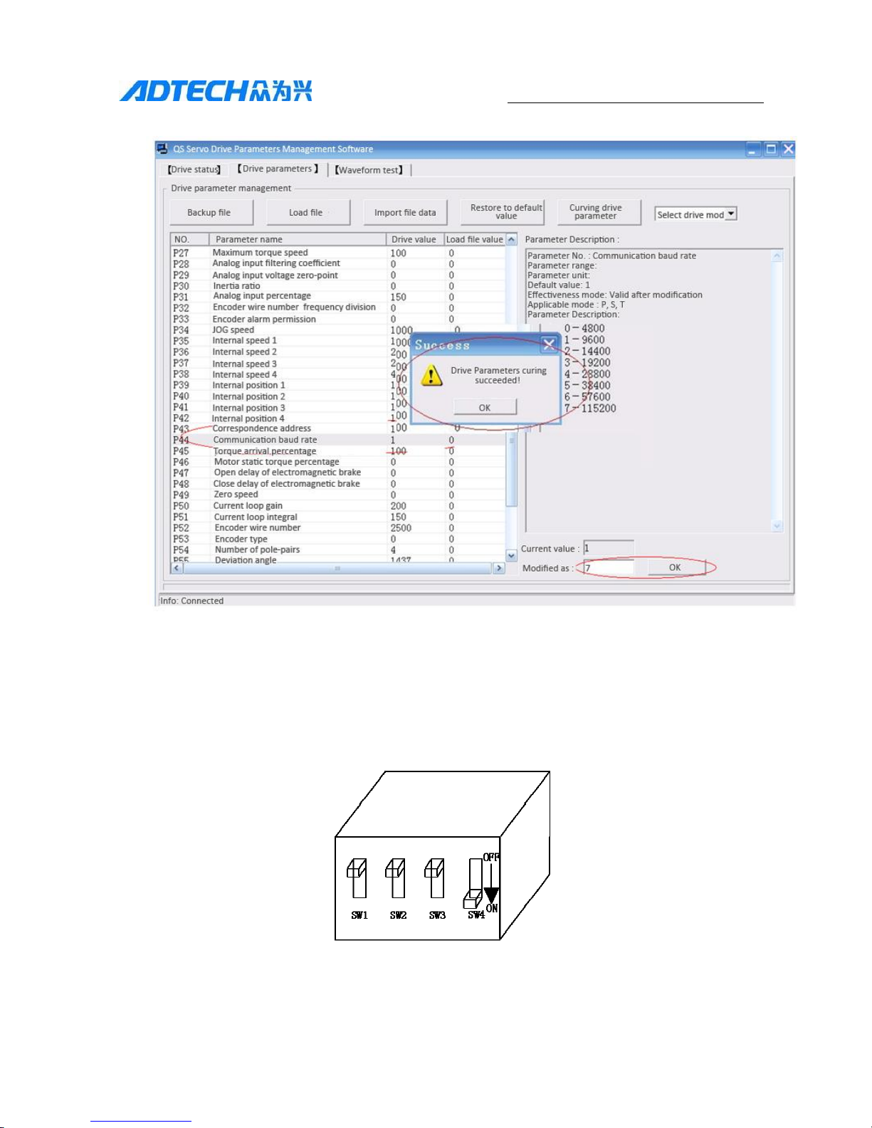
(3) After changing P44 to 7, click OK to modify, and you can see that P44 has
been changed to 7 in "Drive Values" on the left.
Page 37
37
QS2 Series Low Voltage Servo Drive
(4) Click Cure parameters to cut off power of the drive.
(5) SW4 is changed from 0(off) to 1(on), and is powered up normally after
connecting the drive. Communication mode is RS232.
Page 38
38
QS2 Series Low Voltage Servo Drive
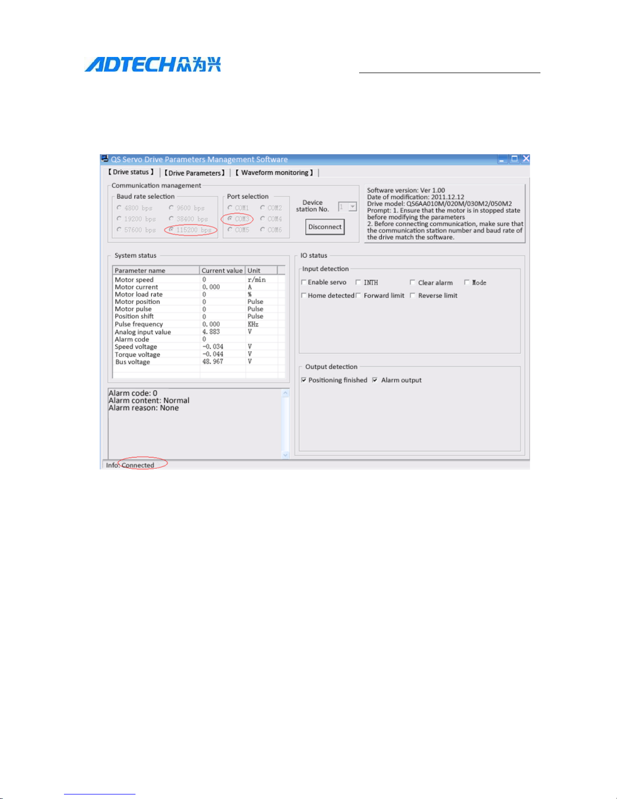
(6) Re-open "QS Servo Drives Parameters Management Software", select the
communication baud rate to 115200, select the correct port (COM3), click
Connect, and the communication connection is OK.
Page 39
39
QS2 Series Low Voltage Servo Drive
Chapter 6 Low-voltage Servo Drive
Parameter Adjustment
After successful communication, adjust the parameters of the stepper drive through
parameter management software to achieve the best operating results.
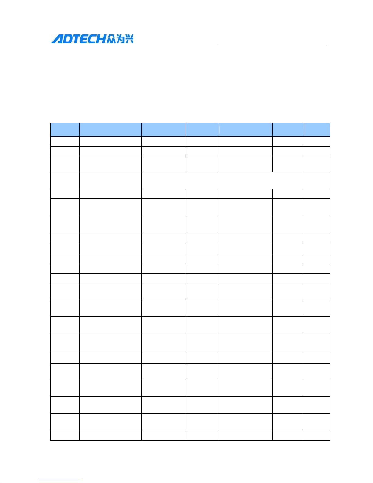
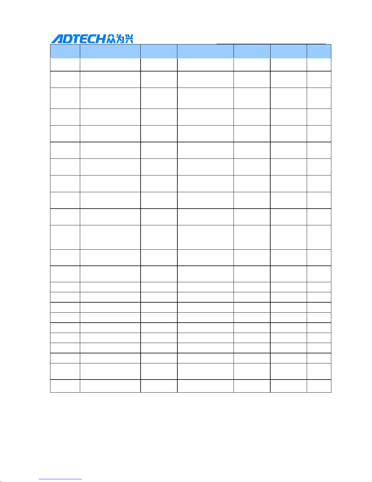
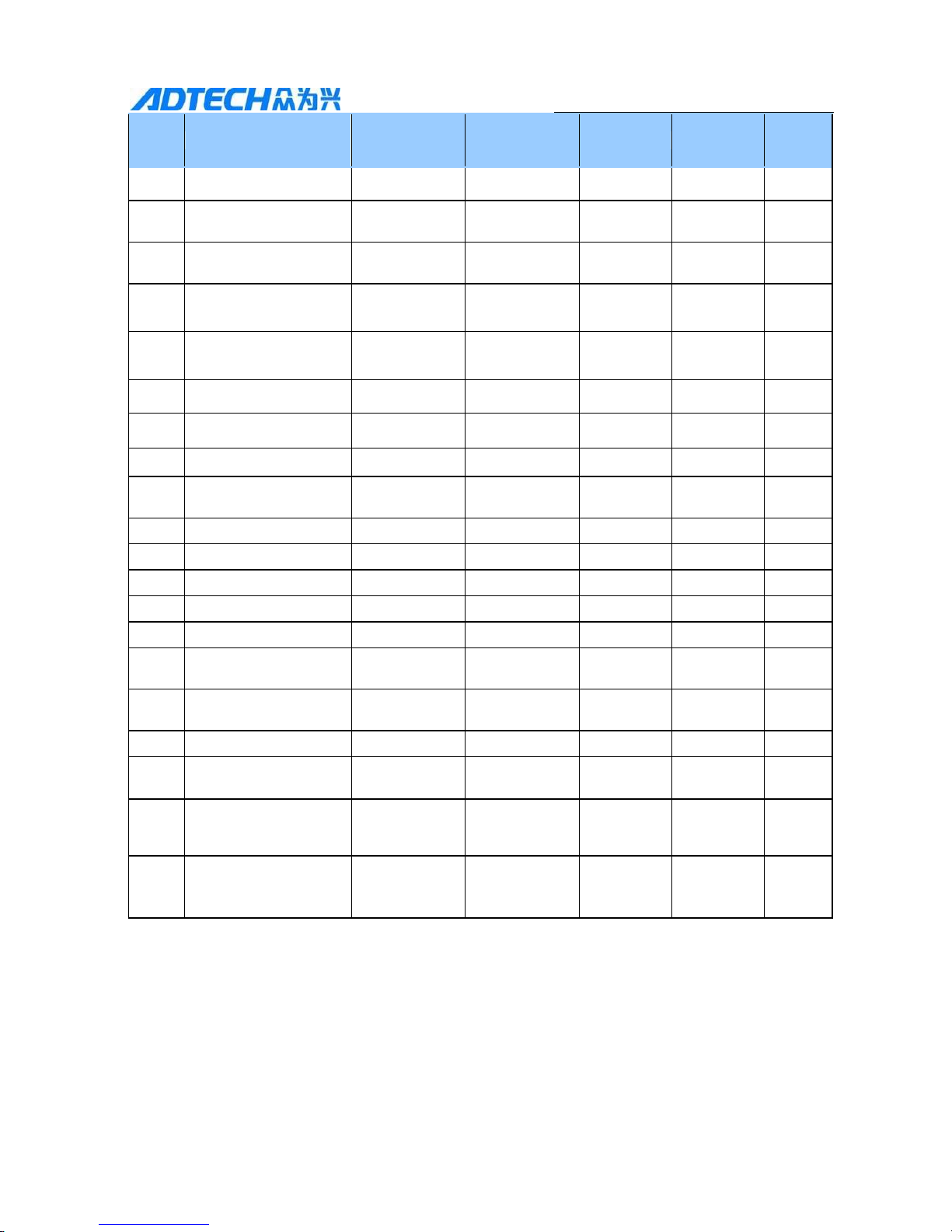
6.1 List of Parameters
Parameter
Name
Mode
Range
Default
Unit
Remark
P0
Software version
P,
S, T
0-9999
Read only
②
P1
Hardware version
P,
S, T
0-9999
Read only
②
P2
Motor model
P,
S, T
0-9999
Read only
Motor
power
③
P3
U, V and W value
Read only, when motor rotates clockwise, it displays 513264 with normal
connection.
P4
Control mode
P,
S, T
0-9
0
①
P5
Servo enable control
P,
S, T
0-1
0
①
P6
Function of servo
input INTH
Function of
reservation
P7
Limit input control
P
0-4
0
①
P8
Coin output mode
P,
S, T
0-1
0
①
P9
Alarm output mode
P,
S, T
0-1
0
①
P10
Pulse mode
P
0-3
0
P11
Motor direction
P,
S
0-1
0
①
P12
Electronic gear
numerator
P
1-32000
1
①
P13
Electronic gear
denominator
P
1-32000
1
①
P14
Range of positioning
completion
P
0-32000
0
Pulse
①
P15
Alarm range of
positioning deviation
P
0-32000
0
Pulse
①
P16
Position gain
P
1-2000
50
①
P17
Position feed forward
P
0-32000
0
①
P18
Position smoothing
coefficient
P
0-1000
0
①
P19
Position accelerating
time
P
0-32000
0
①
P20
Position decelerating
time
P
0-32000
0
①
P21
Speed gain
P,
S
1-1000
100
①
Page 40
40
QS2 Series Low Voltage Servo Drive
Parameter
Name
Mode
Range
Default
Unit
Remark
P22
Speed integral
P,
S
1-32000
500
①
P23
Position acceleration
time (speed)
S
0 -32000(ms)
100
ms
①
P24
Position deceleration
time (speed)
S
0 -
32000(ms)
100
ms
①
P25
Analog input mode
S,
T
0-1
0
①
P26
Analog maximum
speed
S
1-5000
2000
r/min
①
P27
Maximum torque speed
T
1-5000
2000
r/min
①
P28
Analog input
coefficient filtering
S,
T
0-1000
0
①
P29
Analog input point of
zero voltage
S,
T 0
①
P30
Inertia ratio
P, T S,
0-1000
0 ①
P31
Analog input
percentage
S, T 0-500
0 % ①
P32
Encoder wire number
frequency division
P,
S,
T
0-127
0 ③
P33
Encoder alarm
permission
P,
S,
T
0-1
0 ①
P34
JOG speed
Reservation
function
P35
Internal speed 1
S
0-5000
100
r/min
①
P36
Internal speed 2
S
0-5000
200
r/min
①
P37
Internal speed 3
S
0-5000
300
r/min
①
P38
Internal speed 4
S
0-5000
400
r/min
①
P39
Internal position 1
P
0-±32000
100
Pulse
①
P40
Internal position 2
P
0-±32000
200
Pulse
①
P41
Internal position 3
P
0-±32000
300
Pulse
①
P42
Internal position 4
P
0-±32000
400
Pulse
①
P43
Correspondence
address
P,
S,
T
0-255
1
①
P44
Baud rate
P,
S, T 4800-11520
9600
①
Page 41
41
QS2 Series Low Voltage Servo Drive
Parame
ter
Name
Mode
Range
Default
Unit
Remark
0
P45
Torque reaching
percentage
P,
S,
T
0-100
100
%
①
P46
Motor static torque
percentage
P
0-100
0
%
①
P47
Electromagnetic brake
opening delay
Reservation
function
P48
Electromagnetic brake
closing delay
Reservation
function
P49
Zero speed
P,
S, T 0-2000
0
Rpm
①
P50
Current loop gain
P,
S, T 10-4000
600 ①
P51
Current loop integral
P,
S, T 1-2000
150 ①
P52
Encoder wire number
P,
S,
T
1000-6000
2500 ③
P53
Encoder type
P,
S,
T
0-1
0 ③
P54
Number of pole pairs
P,
S,
T
2-6
4 ③
P55
Deviation angle
P,
S, T 0—2500
210 ③
P56
Rated current
P,
S,
T
0-100
28
0.1A
③
P57
Rated torque
P,
S, T 0-200
13
0.1NM
③
P58
Second electron gear
numerator
P
1-3200
1 ①
P59
Second electron gear
denominator
P
1-3200
1 ①
P60
Filtering coefficient
P,
S,
T
0-9
0 ①
P61
Drive type
Reservation
function
P62
V phase current zero
point rectification
value
P,
S, T 2008-2088
2051 ②
P63
W phase current zero
point rectification
value
P,
S, T 2008-2076
2053 ②
Note: (Remarks ①, ② and ③ in the table have the following meanings)
① The parameter takes effect immediately after changing.
② The parameter can’t be modified.
③ Restart the device to take effect after modification.
Page 42
42
QS2 Series Low Voltage Servo Drive
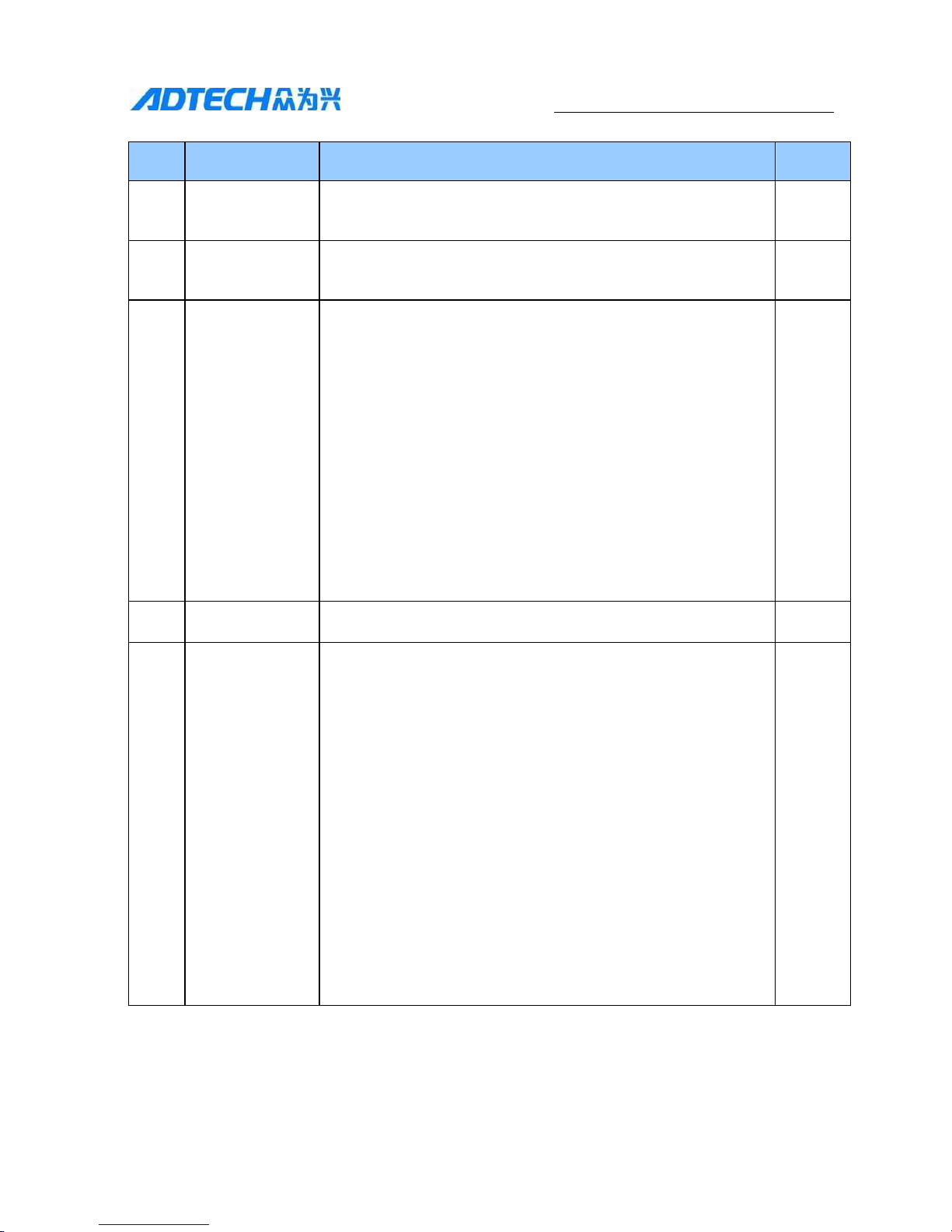
6.2 Parameter Description
No.
Parameter name
Function
Range
P0
Software version
Read only, display different versions
100010XX
P1
Hardware version
Read only, display different versions
100010XX
P2
Motor model
Read only, the use need to modify the following parameters
according to the motor
P52—encoder wire;
P53—encoder type;
P54—pole pairs;
P55—deviation angle;
P56—rated current;
P57—rated torque;
P3
UVW value
The motor rotor rotates clockwise, indicating 5, 1, 3, 2, 6, 4
P4
Control mode
0-position mode external pulse input
1-deviation angle test mode
2-speed mode external analog voltage input
3-torque mode external analog voltage input
4-position and speed mode MODE control
5-position and torque mode MODE control
6-CW CCW external signal inching
0-9
Page 43
43
QS2 Series Low Voltage Servo Drive
No.
Parameter name
Function
Range
7-4 gear speed control
8-4 gear position control
9-communication control
P5
Servo enable
control
0-valid;
1-invalid compulsory axis locking
0-1
P6
Function of
servo input
signal INTH
Not support reservation function for now
0-1
P7
Limit input
control
0-invalid;
0-4
1-valid in low level with no alarm;
2-valid in high level with no alarm;
3-valid in low level with alarm;
4-valid in high level with alarm;
P8
COIN output
mode
0-positioning completion;
1-torque arrival;
2-output when speed less than P49 (if 如 P49 is
less than 10RPM, deemed as 10RPM);
0-2
P9
Alarm output
mode
0-normally closed type;
1-normally open type;
0-1
P10
Pulse mode
0-pulse+direction (100K)
0-3
Page 44
44
QS2 Series Low Voltage Servo Drive
No.
Parameter name
Function
Range
1-pulse+pulse
2-quadrate pulse
3-pulse+direction (500K)
Read only, it can only be set by dial switch SW1/SW2.
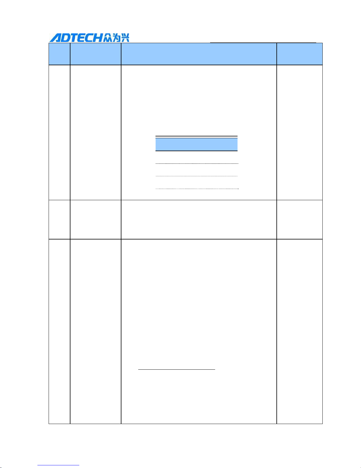
SW1 SW2
00=P+D 100khz
01=CCW+CW 100khz
10=A+B 100khz
11= P+D 500Khz
P11
Motor direction
0 - forward;
1 - reverse;
0-1
P12
Set sub-frequency multiplication of position command
pulse (electronic gear);
In electronic gear ratio control mode, set parameter P12
and P13 to easily achieve pulse equivalent matching;
considering that the acceptable frequency range of the
drive is lower than 500K, increase the value as much as
possible;
1-32000
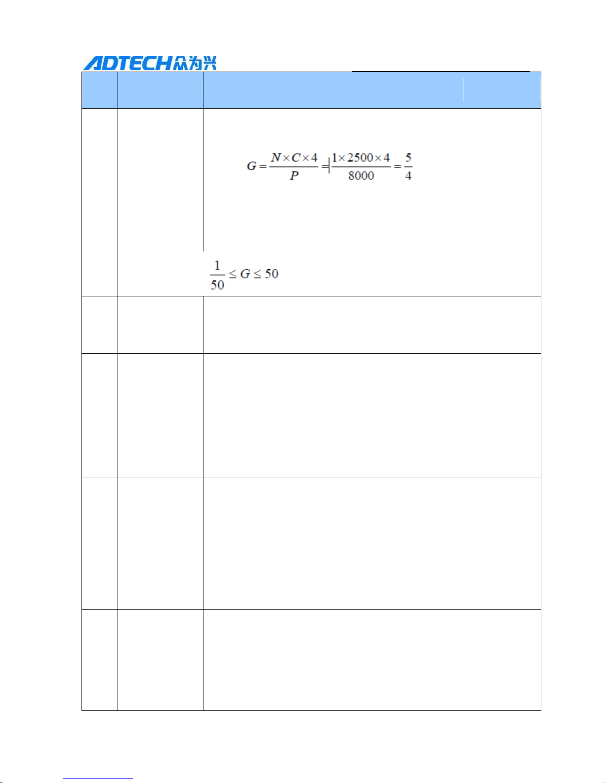
P×G=N×C×4
Electronic gear
numerator
P:pulse number of input instruction;
G:electronic gear ratio;
Frequency division numerator
G
Frequency division denominator
N:motor rotation number;
C:wire number of photoelectrical encoder: generally
2500;
Page 45
45
QS2 Series Low Voltage Servo Drive
No.
Parameter name
Function
Range
[For example] when the input instruction pulse
required is 8000, the servo drive rotates for a round.
The parameter P12 is 5, P13 is set as 4;
The recommended range of electronic gear ratio shall
be:
P13
Electronic gear
denominator
Same as above parameter P12;
1-32000
P14
Range of
positioning
completion
The positioning completion pulse range under the
setting position control mode; the parameter provides
the foundation to judge if the positioning competed
under the position control mode. when the residual
pulse number in the position deviation counter is less
or equal to the setting of the parameter, the drive shall
be supposed that the positioning has been done and the
signal with COIN ON, otherwise with COIN OFF;
0-32000
P15
Alarm range for
position overweight
When set as 0, the over-weight alarm detection is
invalid; when it is not at 0, the over-weight alarm
detection is valid and the parameter can judge if the
over-weight is too large under the position control
mode. when residual pulse number in the position
deviation counter is less or equal to the setting of the
parameter, the drive will suppose there is no overweight with no alarm; otherwise with alarm indicating
ER0-04
0-32000
P16
Position gain
Set the proportion gain of the position loop regulator.
Larger the setting value is, higher the gain is and
larger the inflexibility is and smaller the position lag is
under the condition of same frequency instruction
pulse, but too large value will cause system
fluctuation and overshoot;
1-2000
Page 46
46
QS2 Series Low Voltage Servo Drive
No.
Parameter name
Function
Range
As for debugging, it shall adjust the parameter as
large as possible under the condition of system
operation with no fluctuation and vibration
P17
Position feed
forward
Set the position feed forward coefficient; setting
as 0 does not need to add feed forward; the larger
the setting value is, the larger the feed forward is;
The large the feed forward of the position loop,
the better the high speed response characteristic
of the control system is;
0-32000
P18
Position
smoothing
coefficient
Set the smooth filtering of the instruction pulse
with an acceleration and deceleration of
exponential form. The value means the
acceleration and deceleration;
0-1000
The filtering will not lose pulse but has phenomenon
of instruction delay;
Mainly used in:
➢ The upper computer controller without
acceleration and deceleration function;
➢ The electronic gear frequency is large (larger
than 8);
➢ Slow motor operation and low pulse frequency;
➢ Motor operation with phenomenon of stepping
jump and instability;
➢ The filter takes no effect when setting as 0;
P19
Position
Acceleration
time
The greater the value is, shorter the acceleration time is
and faster the positioning is; it is only valid in
internal mode
0-32000
P20
Position
deceleratio
n time
The greater the value is, shorter the acceleration time
is and faster the positioning is; it is only valid in
internal mode
0-32000
P21
Speed gain
Set the proportion gain of the speed loop regulator;
1-1000
Page 47
47
QS2 Series Low Voltage Servo Drive
No.
Parameter name
Function
Range
Larger the setting value is, larger the gain is and
larger the inflexibility is. It shall be determined
according to the specific servo drive model and load
situation. Generally, larger the load inertia is, larger
the setting value is;
It shall be tried to set as large as possible under the
system without fluctuation;
P22
Speed integral
Set the integration time constant of speed loop
regulator;
Larger the setting value is, faster the integral speed is,
stronger the anti-deviation of the system is and larger
the inflexibility is;
1-32000
P23
Acceleration
time (speed)
The setting value represents the acceleration time of
the motor from 0 to 1,000R/MIN;
0-
32,000(MS
)
The feature of acceleration and deceleration is linear;
It is valid in speed control mode and torque control
mode but invalid in position control mode;
P24
Deceleration
time (speed)
The setting value represents the deceleration time of
motor from 1000 to 0 R/MIN;
The feature of acceleration and deceleration is linear;
It is valid in speed control mode and torque control
mode but invalid in position control mode;
0-
32000(MS)
P25
Analog input
mode
0-AD input value 1- fixed application of P35 value;
0-1
P26
Analog
maximum
speed
Means the corresponding speed when the analog input
at its maximum;
1-5000
Page 48
48
QS2 Series Low Voltage Servo Drive
No.
Parameter name
Function
Range
P27
Maximum torque
speed
Means the restricted maximum speed in the torque
mode;
1-5000
P28
Analog input
filtering
coefficient
0-prohibition;
0-1000
P29
Analog input
voltage point
of zero voltage
Simulation of the zero point corresponded to the point
when the voltage output 0V;
0
P30
Maximum
output torque
0-1000
P31
Analog input
percentage
0-equivalent to 100%;
0-500
P32
Encoder wire
number
frequency
division
0-not use frequency division, the setting value is N,
representing the encoder A and B phase output
frequency;
0-127
P33
Encoder alarm
permission
0-detection of encoder 1-no detection of encoder;
0-1
P34
JOG speed
Reservation function not available for now
The setting of speed when JOG is operating;
0-5000
P35
Internal speed 1
The set speed is 1 when operating in an internal 4stage speed control mode;
0-5000
P36
Internal speed 2
The set speed is 2 when operating in an internal 4stage speed control mode;
0-5000
P37
Internal speed 3
The set speed is 3 when operating in a internal 4-stage
speed control mode;
0-5000
Page 49
49
QS2 Series Low Voltage Servo Drive
No.
Parameter name
Function
Range
P38
Internal speed 4
The set speed is 4 when operating in a internal 4-stage
speed control mode;
0-5000
P39
Internal
position 1
The set speed is 1 when operating in an internal 4stage speed control mode;
0-±32000
P40
Internal
position 2
The set position is 2 when operating in an internal 4stage position control mode;
0-±32000
P41
Internal
position 3
The set position is 3 when operating in an internal 4stage position control mode;
0-±32000
P42
Internal
position 4
The set position is 4 when operating in an internal 4stage position control mode;
0-±32000
P43
Correspondence
address
1
0-255
P44
Communication
baud rate
0--4800,1-9600,2-14400,3-19200,4,5-38400,6-57600,
7-115200;
0-7
P45
Torque arrival
percentage
Set the proportion between the set analog quantity
torque input voltage and the actual motor
operating torque;
Unit of the setting value is 0.1V/100%;
Default value is 100 with 10V/100%,which means
inputting 10V voltage will generate 100% rated
torque;
0-100
P46
Percentage of
motor static
torque
The torque of shaft locking when motor stops;
The unit of setting value is when the position loop is
valid , the speed loop and torque loop are invalid; the
set unit: the rated torque×100%;
0-disable this function;
Other values—this function available
0-100
P47
Open delay of the
electromagneti
c brake
Reservation function not available for now
0-32000
Page 50
50
QS2 Series Low Voltage Servo Drive
No.
Parameter name
Function
Range
Define the motor enable shaft locking (input terminal
SON switched from OFF to ON); till the delay time of
open the brake. (output terminal BRK switched from
OFF to ON);
This parameter is used to switch from brake shaft
locking to motor enable shaft locking smoothly when
the motor is electrified;
(MS)
P48
Close delay of
the
electromagne
tic brake
Reservation function not available for now.
Define the motor to release the enable (input terminal
SON switched from ON to OFF)
Till the delay time of open the brake. (output terminal
BRK switched from OFF to ON);
This parameter is used to switch from brake shaft
locking to motor enable shaft locking smoothly when
the motor is electrified;
The parameter can be prolonged when the motor
operates from a high speed to halt, strengthening the
emergency stop effect;
0-32000
(MS)
P49
Zero-speed
Motor will stop if less than the value
0-2000
P50
Current loop gain
Large the motor current, largely can the current loop
gain be adjusted. When the motor’s noise is very
large, it needs no adjustment;
Default value is 600;
10-4000
P51
Current loop
integral
Large the motor current, largely can the current
loop integral be adjusted. When the motor’s noise
is very large, it needs no adjustment;
Default value 150;
1-2000
P52
Encoder wire
number
Only the motor model set as (P2=9999) can the
parameter be valid;
1000-6000
Page 51
51
QS2 Series Low Voltage Servo Drive
No.
Parameter name
Function
Range
Input the encoder wire number of the motor, generally
1024, 2048, 2500, 3000 and 5000;
Note that the it needs restarting after modification of the
parameter to make it valid; default value is 2500;
P53
Encoder type
Only the motor model set as (P2=9999) can the parameter be
valid;
Setting as 0 means the common non-wire-saving encoder while
setting as 1 means wire-saving;
Note that the it needs restarting after modification of the
parameter to make it valid; default value is 0;
0-1
P54
Number of
pole-pairs
Only the motor model set as (P2=9999) can the parameter be
valid;
The setting value means the number of pole-pairs
Note that the it needs restarting after modification of the
parameter to make it valid; default value is 4;
2-6
P55
Deviation
angle
The setting value means the deviation angle of the motor
between the electric degree and zero-point;
note that the it needs restarting after modification of the
parameter to make it valid; default value is 210;
0-
2500
P56
Rated current
Only the motor model set as (P2=9999) can the parameter be
valid;
The setting value means the rated current of the motor, only
affecting the current protection function of the motor but not
the operation of the motor;
Setting unit (0.1A)
0-
100
Page 52
52
QS2 Series Low Voltage Servo Drive
No.
Parameter name
Function
Range
P57
Rated torque
Only the motor model set as (P2=9999) can the
parameter be valid;
The setting value means the rated torque of the motor,
only affecting the torque protection function of the
motor but not the operation of the motor;
Unit (0.1NM)
0-200
P58
Second
electronic gear
ratio numerator
Usage same as the first electronic gear ratio;
0-500
P59
Second electronic
gear ratio
denominator
Usage same as the first electronic gear ratio;
0-500
P60
Filtering
coefficient
Used to motor noise when the speed loop gain is too
large;
0—9
P61
Drive current
type
Reserved
P62
V phase current
zero-point
rectification
value
It means the float value of V phase current zero-point.
2008-2088
P63
W phase
current zeropoint
It means the float value of W phase current zeropoint.
2008-2076
It is recommended to set and modify all parameters when the motor is stationary;
Before long-term storage, the parameters must be solidified and written;
When the drive power is cut off, wait at least 30 seconds before powering up again;
When the drive is used in numerical control system, the parameter P12 and P13 shall be
calculated as follows:
P12 Mechanical deceleration ratioSystem pulse equivalency10000
P13 Lead screw pitch (mm)
The pulse equivalency of general numerical control system is 0.001mm.
Page 53
QS2 Series Low-voltage Servo
53
6.3 Adjustment of PID Parameter
The servo system, adopted with PID regulation, is a feed-back system with
current loop, speed loop and position loop. The general principle followed is that:
the closer the loop is to the inner side, the higher the responsiveness should be.
Overshoot and vibration will occur without following the principle. Usually, the
current will not be modified as it ensures the responsiveness. Adjustment mainly
happened to position and speed loop.
Steps of servo debugging (position model): (1) set the speed loop integral to a
large value; (2) set the position loop gain to a small value and increase the
speed loop gain within a range that cause no vibration and abnormal sound;
(3) decrease the speed loop integral without causing vibration; (4) increase
position loop gain until vibration disappear; (5) properly modify the position
filter coefficient P18 to keep it running smoothly.
Recommended value
Item
Low rigidity
Medium rigidity
High rigidity
Position loop gain
50
80
100
Speed loop gain
100
200
300
Speed loop integral
500
500
500
Knowledge on rigidity of mechanical system:
The belt conveyor is of low rigidity, the low rigidity parameter can be applied;
Reducer drive ball screw is of medium rigidity, the medium rigidity parameter can be
applied;
Motor directly drive ball screw is of high rigidity, the high rigidity parameter can be
applied.
Page 54
QS2 Series Low-voltage Servo
54
6.4 Adjustment of Other Parameters
Other parameters are adjusted according to the system condition. Main
adjustment parameters for reference under position mode are listed in the table:
NO.
Parameter name
Function
P0
Software version
Software version, only for reading
P2
Motor model
Read only
P4
Choose control type
0=position mode, 2=speed mode, 3=moment mode
P5
Servo enable
0=motor shaft unlocked, 1=motor excitation, shaft locked
P9
Alarm switch
0= normally closed, 1= output normally open signal when
alarm is detected
P11
Selection of motor
direction
0= default motor direction, 1= reverse direction
P12
Electrical gear
denominator
Set up the pulses per revolution
P13
Electrical gear
denominator
Set up the pulses per revolution
P49
Zero speed clamp
The motor stop when rotate speed is lower than this value,
default value is 0
P60
Filter coefficient
Eliminate the noise produced by large speed loop integral
Page 55
QS2 Series Low-voltage Servo
55
Chapter 7 Operation
After finishing install and line connecting, check the following items prior to power
connection:
Are the sub-lines correct or fixed? Is the input voltage correct?
Is there a short circuit in power line or motor line?
Has the control signal terminal been properly connected? Is the power polar or the
current magnitude correct?
Have the drive and the motor been fixed firmly?
Does the motor connected load?
Does the motor and the drive assort with each other in specification?
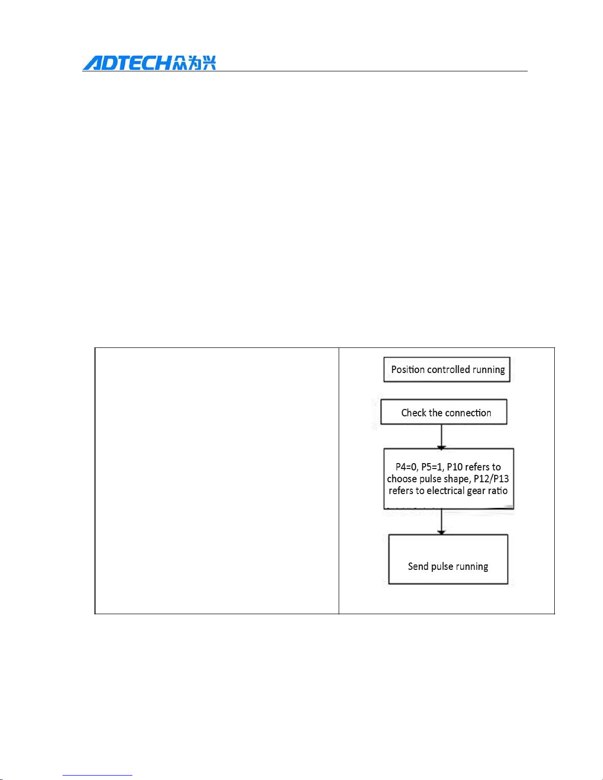
7.1 Position control
1. When P4=0, the system is under
position mode, the operation rotational
speed and distance are controlled by
external pulse.
2. When P=5 or the external interface EN
is valid, the servo enable signals valid and
the motor operates.
4. When P6 is not 0, the drive will be set to
“intelligent position mode” forcibly. The
Rigidity of the system can be modified by
modifying P6, without modifying P16, P21
or P22. (Note: only version higher than
1010 has intelligent mode. And the
parameter management software of upper
machine matched must be version 1.05.)
Page 56
QS2 Series Low-voltage Servo
56
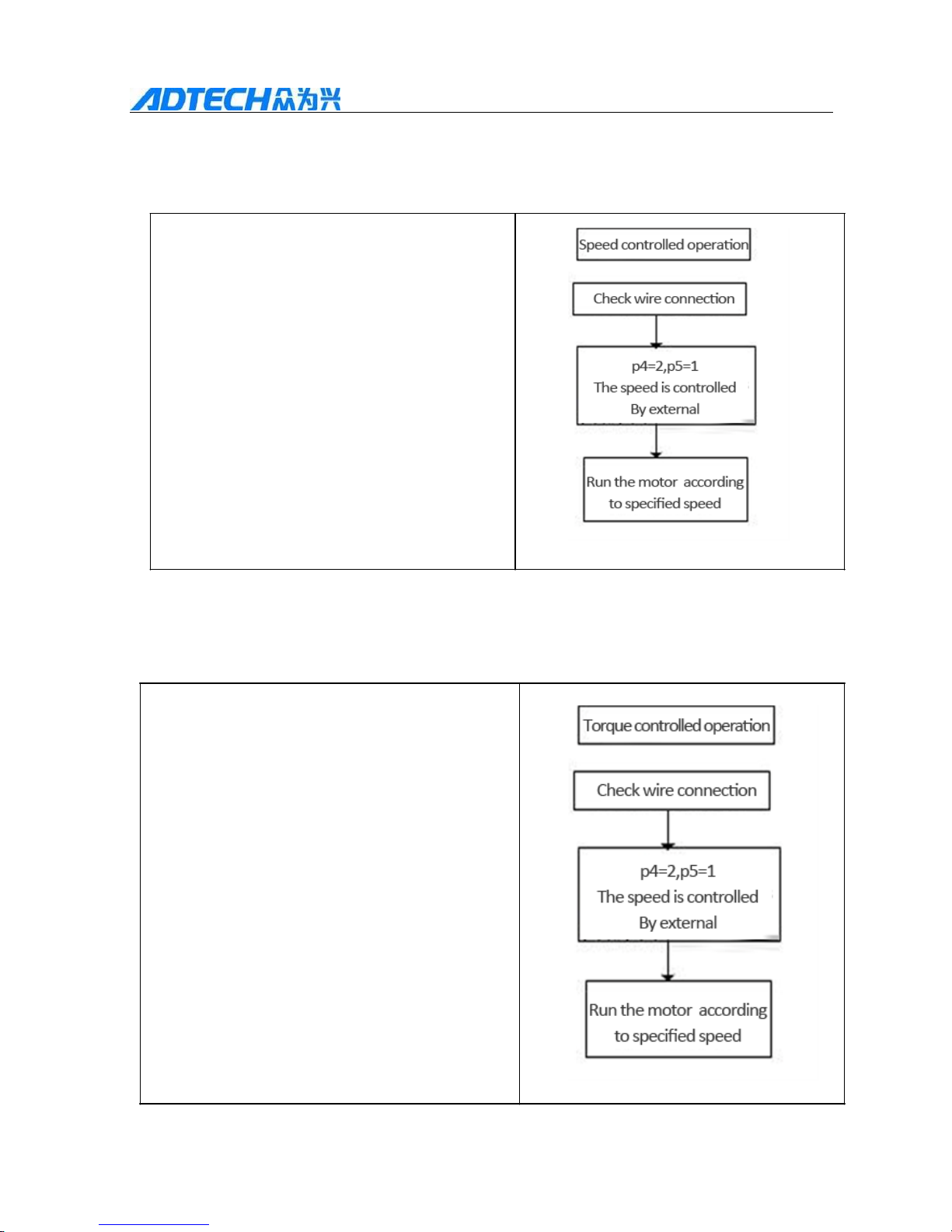
7.2 Speed control
1. When P4=2, the system is under
speed mode
2. When P5=1 or EN signal is
valid, the motor start running.
3. When P25=1, motor speed is
controlled only by inter parameter,
motor speed is ± (P35/2024) *P26 rpm.
4. When P25=0, the motor speed is
determined by voltage between pin 20
and pin 19 of CN1 port. Revolution is ±
(VIN/10V)*P26 rpm.
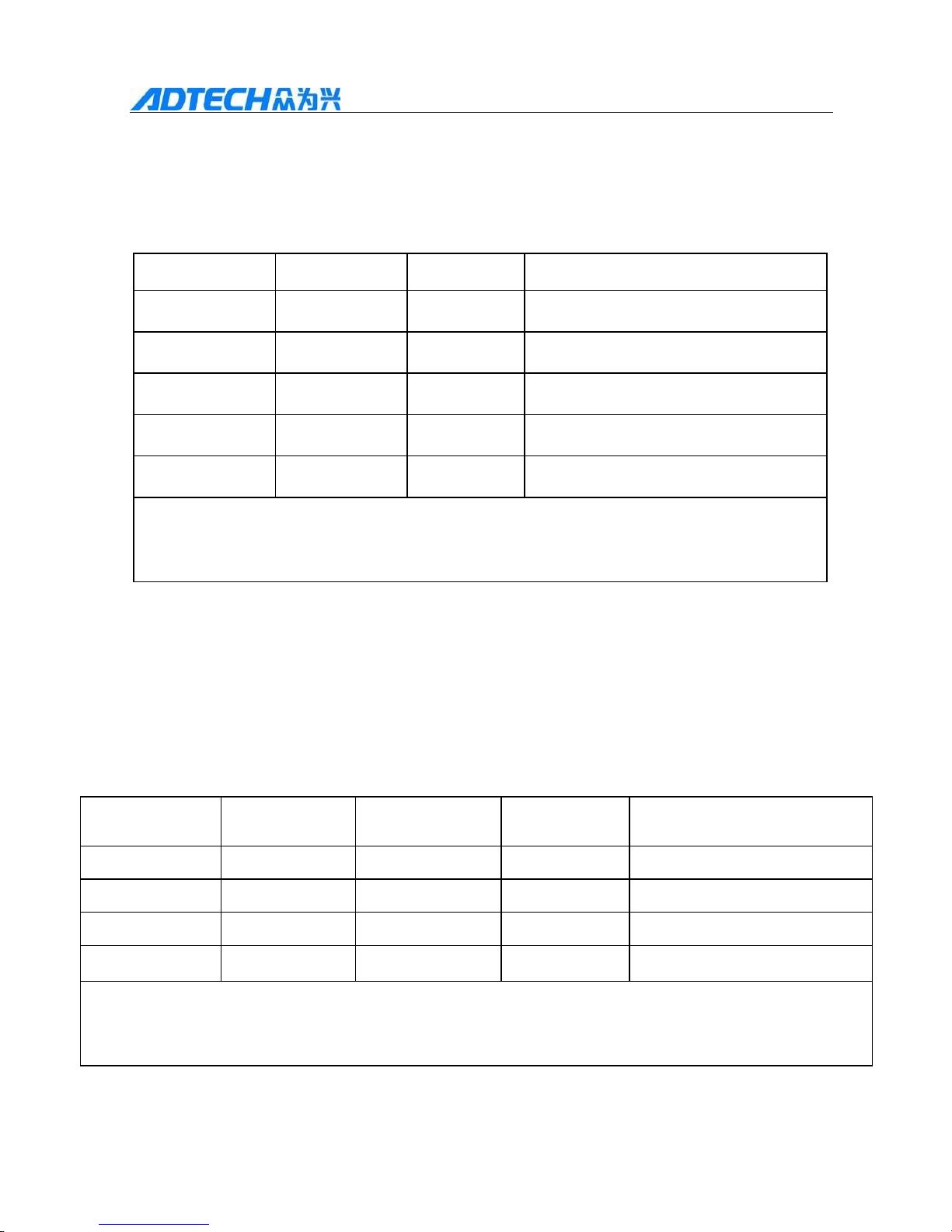
7.3 Torque control
1. When P4=3, the system is under
moment mode.
2. When P5=1or EN is valid, the
motor operates.
3. When P25=1, the moment is
controlled only by inter parameter,
maximum output torque is ±
(P36/2048)*P56, current unit: A.
4. When P25=0, the maximum output
torque is determined by TIN, which
existed between pin 21 and pin 22 of CN1.
The torque is ± (TIN/10V)*P56, current
unit: A.
5. During the running process, the
speed will not over P27.
Torque controlled operation
Page 57
QS2 Series Low-voltage Servo
57
7.4 Internal 4-stage Speed Control
When P4=7, the servo system is under internal 4-stage control. If the input
signal MODE (level signal) is valid, the motor operates. Motor speed is
determined by input signals CW and CCW. See the following table:
MODE signal
CCW signal
CW signal
Motor speed
1 1 1 0 1 0 0
P35
1 0 1
P36
1 1 0
P37
1 1 1
P38
Note: 1 in table above is for the signal is valid, 0 for the signal is invalid. For the
drive, low level signal input by MODE CWW CW is valid, while high level
signal or left signal is invalid.
7.5 Internal 4-stage Position Control
When P4=8, the servo system is under internal 4-stage position control. If the input
signal MODE (level signal) is valid, the motor operates. Motor speed is determined by
input signals CW and CCW. See the following table:
MODE signal
CCW signal
CW signal
Operation
Operation length
1 0 0
P35
P41* (P12/P13)
1 0 1
P36
P42* (P12/P13)
1 1 0
P37
P43* (P12/P13)
1 1 1
P38
P44* (P12/P13)
Note: 1 in table above means the signal is valid, 0 means the signal is invalid. For the drive,
low level signal input by MODE, CWW and CW is valid, while high level signal or left
signal is invalid.
Page 58

QS2 Series Low-voltage Servo
58
Chapter 8 Common Problems
Common problems occurred in operation of servo system:
(1) Direction of motor rotation is contrary
to expected
Possible cause: wrong connection of
UVW
Solution: method 1: check and correct UVW connection. Method 2: set P11 at 1
without changing wire connection.
(2) After shaft locking, possible reason of motor run error:
encoder error or phase deficient or deviation angle error.
Solution: check encoder and motor wires and re-measure
deviation angle.
(3) Possible causes of large no-load motor current:
incorrect deviation angle.
Solution: Re-measure deviation angle and then solidified parameter and restart
the drive.
(4) Possible causes for unable to connect to PC: wrong communication mode.
Solution: check the setup and make it correspond to practical situation, SW3=3
refer to 285 communications, SW3=on refers to 232 communications. Meanwhile,
SW4=4 refers to default baud rate 9600, SW4=on refers to client configuration.
(5) Possible causes for communication failure
during use: poor stability of USB
converter:
Solution 1: Disconnect the PC interface first, then re-up electricity and
reconnect.
Solution 2: use USB converter recommended by Adthch.
Solution 3: use computer configured serial.
Page 59
QS2 Series Low-voltage Servo
59
(6)Possible causes for triggering over-voltage alarm by
sudden stop of motor: no brake resistance.
Solution methods: external attach brake resistance.
(7) Possible causes for triggering low-voltage
alarm by high speed start: poor linevoltage regulation. Solution methods:
replace it with a high quality switching
power supply.
(8)Possible causes for that the drive cannot receive pulses and stop after short-time
running: SW1=0 and SW2=0, the signal is filtered when its frequency is higher
than 100KHz. Solution methods: set SW1 and SW2 at 11.
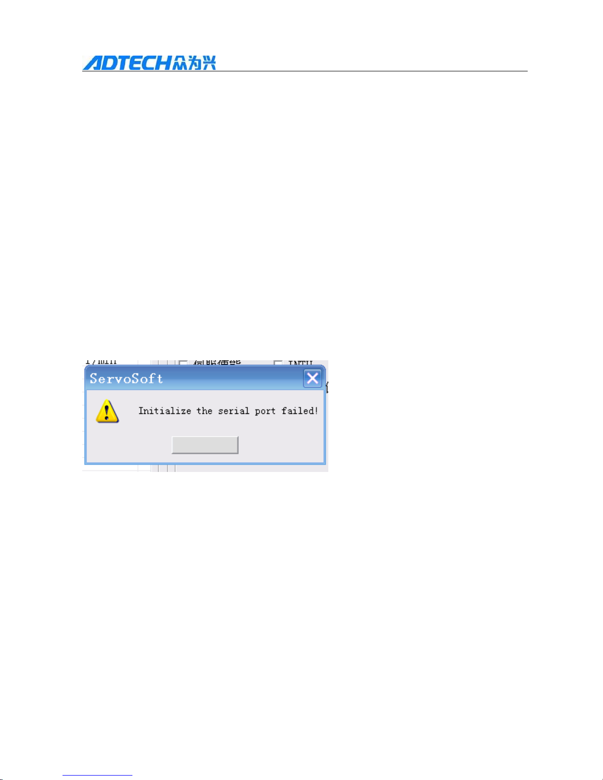
(9) The serial port cannot be connected, as shown in the picture:
Possible causes:
1. Choose a wrong serial port.
2. Solution methods for install USB converter drive
program improperly:
Method 1: check the “device manager” and chose a correct port.
Method 2: reinstall USB to serial port or USB to 485 drive program.
OK
Page 60
QS2 Series Low-voltage Servo
60
Chapter 9 Delivery Note
This chapter describes the list about products available for customer to buy. Some of
them are optional components, please chose according to you needs.
Material
code
Material
name
Model
Power
W
Voltage
V
Shaft
diameter
504H3000003
Servo motor
ACL06040B-2B
400
60
14
502H3000003
Servo motor
ACL06020A-2A
200
36
11
502H3000004
Servo motor
ACL06020A-2B
200
36
14
501H3000002
Servo motor
ACL06010A-2A
100
36
8
501H3000001
Servo motor
ACL06010A-2B
100
36
11
Material code
Material name
Model
Remarks
See the model
Pulse line
26 pin head
(E63AG261101)
No wire, DB head only
for customer to connect
Shell (E63A0150001)
QS208020M
pulse control
line (position
mode)
Standard, universal type
Control line of drive
CD1YF1M5001
QS2 low-
voltage servo
wire
D1YF-1M5
Consisted of the
encoder wire+ power
wire, two one-meter
long wire
CQS2USB1M01
Communication
line
QS2-USB-232
Communication line
connected the PC and the
drive, RS232 type
CQS2USB5M01
Communication
line
QS2/QS7-USB-485
Communication line
connected the PC and
the drive, RS232
Page 61
QS2 Series Low-voltage Servo
61
E01A0710001
Brake resistance
25Ω , 60W
Optional component,
applied when the
inertia is large
E34A1500251
Switching power
supply
68V, 500W, be applied
to 60V motor
Be applied to 60V
servo motor
E34A1350291
Switching power
supply
350W, input
100~120VAC/200~
240VAC (change
over switch), output
Be applied to 36V
motor
 Loading...