


|
American DJ® |
|
|
Vizi Scan LED PRO |
|
|
Table of Contents |
|
General Information..................................................................... |
4 |
|
Features......................................................................... |
4 |
|
Safety Precautions...................................................................... |
5 |
|
Registration...................................................................... |
6 |
|
Handling Precautions.................................................................. |
6 |
|
Mounting................................................................................. |
7 |
|
Controls and Functions.............................................................. |
9 |
|
DMX Set-Up.............................................................................. |
12 |
|
System Menu............................................................................ |
15 |
|
Editing Program......................................................................... |
33 |
|
Operating Modes....................................................................... |
38 |
|
DMX Traits................................................................................. |
40 |
|
Fuse |
Replacement.................................................................... |
47 |
Gobo |
Replacement................................................................... |
48 |
Photometric Chart..................................................................... |
49 |
|
Cleaning.................................................................. |
50 |
|
Trouble Shooting....................................................................... |
50 |
|
Warranty................................................................. |
51 |
|
Specifications.................................................................... |
52 |
|
User Instructions
Rev. 2/11 |
American DJ® - www.americandj.com - Vizi Scan LED PRO Instruction Manual Page 2 |

Vizi Scan LED PRO |
|
General Information |
||
Unpacking: Thank you for purchasing the |
Vizi Scan LED PRO by |
|||
American |
DJ®. Every Vizi Scan LED PRO has |
been thoroughly tested |
||
and |
has |
been shipped in perfect operating condition. Carefully check |
||
the |
shipping carton for damage that may have occurred during ship- |
|||
ping. If the carton appears to be |
damaged, carefully inspect your fix- |
|||
ture for any damage and be sure |
all equipment necessary to operate |
|||
the |
unit has arrived intact. In the event damage has been found or parts |
are |
missing, please contact our toll free customer support number for |
further instructions. Please do not return this unit to your dealer without contacting customer support first.
Introduction: The Vizi Scan LED PRO is a bright, high output, intelligent DMX scanner. The Vizi Scan LED PRO can be either a 12 or 14 DMX Channel unit. The fixture can operate in three different operating modes; sound active, auto run, or DMX control. The fixture can run as a Stand Alone unit or in a Master/Slave configuration. The Vizi Scan LED PRO comes with several built in programs and is best used in multiples of four. For best results use fog or special effects smoke to enhance the beams projections.
During the initial start-up or use of this product a light smoke or smell may arise from the unit. This is a normal process and is cause by the heat associated with the unit.
Customer Support: American |
DJ® provides a toll free customer |
support line, to provide help and |
to answer any question should you |
encounter problems during your |
set up or initial operation. You may |
also visit us on the web at www.americandj.com for any comments or
suggestions. Service |
Hours are Monday through Friday 8:00 a.m. to |
4:30 p.m. Pacific Standard Time. |
|
Voice: |
(800) 322-6337 |
Fax: |
(323) 582-2610 |
E-mail: |
support@americandj.com |
To purchase parts online visit http://parts.americandj.com
Warning! To prevent or reduce the risk of electrical shock or fire, do not expose this unit to rain or moisture.
Warning! This may cause severe eye damage. Avoid looking directly into the light source at all times!
Vizi Scan LED PRO |
Features |
|
• |
Micro-Stepping Motors for Smooth Color and Gobo |
Transitions |
• |
2 DMX Channel Modes - 12 Channel Mode & 14 Channel Mode |
|
• |
Independent Gobo and Color Wheels |
|
•7 Rotating Gobos w/ Shake, 5 Metal and 2 Glass + Spot - All Replaceable
•8 Colors, Plus White - With Rainbow
•Prism Wheel: 3 Facet; Trapezoid; Frost
• RDMX - Lets you set the DMX address from any DMX Controller
•3 Operating Modes - Sound Active, Auto Run, & DMX Control
•Internal Microphone
• Edit and Save Scenes into the Memory
•Remote Focus
•Variable Strobe (1-12 fps)
•Motor Calibration Adjustment
•Pan: 180 Degrees
•Tilt: 35 Degrees
•Mic Sensitivity Adjustment
•Digital Display for Address and Function Setting
Vizi Scan LED PRO |
RDMX |
Regarding RDMX :
1.The units will be shipped preset in 16 channel increments from the factory
2.While using RDMX, if all units are set to the same DMX address, all units will change to the new DMX address you selected.
EXAMPLE: You have four units, and all the units are set to the DMX address of “1”, and you change one unit to DMX address “17”, this will cause all the units to change to DMX address “17”.
All four units must be on 4 different starting addresses to individually set the DMX addresses for each unit.
For more on this feature see pages 25-26.
American DJ® - www.americandj.com - Vizi Scan LED PRO Instruction Manual Page 3 |
American DJ® - www.americandj.com - Vizi Scan LED PRO Instruction Manual Page 4 |

Vizi Scan LED PRO |
Safety Precautions |
For Your Own Personal Safety, Please Read and Understand This Manual Completely Before You Attempt To Install Or Operate This Unit!
• To reduce the risk of electrical shock or fire, do not expose this unit rain or moisture
• Do not spill water or other liquids into or on to your unit.
•Do not attempt to operate this unit if the power cord has been frayed or broken.
•Do not attempt to remove or break off the ground prong from
the electrical cord. This prong is used to reduce the risk of electrical
shock and fire in case of an internal |
short. |
• Disconnect from main power before |
making any type of connection. |
•Do not remove the cover under any conditions. There are no user serviceable parts inside.
• Never operate this unit when it’s cover is removed.
• Always be sure to mount this unit in an area that will allow proper ventilation. Allow about 6” (15cm) between this device and a wall.
•Do not attempt to operate this unit, if it becomes damaged.
•This unit is intended for indoor use only, use of this product outdoors voids all warranties.
• |
Always mount this unit in safe and stable matter. |
• |
Power-supply cords should be routed so that they are not likely to |
be walked on or pinched by items placed upon or against them, paying particular attention to cords at plugs, convenience receptacles, and the point where they exit from the appliance.
• Cleaning -The fixture should be cleaned only as recommended by the manufacturer. See page 50 for cleaning details.
• Heat -This fixture should be situated away from heat sources such as radiators, heat registers, stoves, or other appliances (including amplifiers) that produce heat.
• The fixture should be serviced by qualified service personnel when: A. Objects have fallen, or liquid has been spilled into the appliance.
B.The appliance has been exposed to rain or water.
C.The appliance does not appear to operate normally or exhibits a marked change in performance.
Vizi Scan LED PRO |
General Instructions |
To optimize the performance of this product, please read these operating instructions carefully to familiarize yourself with the basic operations of this unit. These instructions contain important safety information regarding the use and maintenance of this unit. Please keep this manual with the unit, for future reference.
Vizi Scan LED PRO |
Product Registration |
The Vizi Scan LED PRO carries a 3 year (1095 Day) limited warranty. Please fill out the enclosed warranty card to validate your purchase. All returned service items whether under warranty or not, must be freight pre-paid and accompany a return authorization (R.A.) number. The R.A. number must be clearly written on the outside of the return package. A brief description of the problem as well as the R.A. number must also be written down on a piece of paper and included in the shipping carton. If the unit is under warranty, you must provide a copy of your proof of purchase invoice. You may obtain a R.A. number by contacting our customer support team on our toll free customer support number. All packages returned to the service department not displaying a R.A. number on the outside of the package will be returned to the shipper at the shippers cost.
Vizi Scan LED PRO |
Handling Precautions |
Caution! There are no user serviceable parts inside this unit. Do not attempt any repairs yourself, doing so will void your manufactures warranty. In the unlikely event your unit may require service please contact American DJ®.
During operation the housing may become extremely hot. Avoid touching the unit with bare hands while in use.
American DJ® will not accept any liability for any resulting damages caused by the non-observance of this manual or any unauthorized modification to this unit.
American DJ® - www.americandj.com - Vizi Scan LED PRO Instruction Manual Page 5 |
American DJ® - www.americandj.com - Vizi Scan LED PRO Instruction Manual Page 6 |

Vizi Scan LED PRO |
Mounting |
When installing the unit, the trussing or area of installation must be able to hold 10 times the weight without any deformation. When installing the unit must be secured with a secondary safety attachment, e.g. and appropriate safety cable. Never stand directly below the unit when mounting, removing, or servicing the unit.
Overhead mounting requires extensive experience, including calculating working load limits, installation material being used, and periodic safety inspection of all installation material and unit. If you lack these qualifications, do not attempt the installation yourself.
These installation should be checked by a skilled person once a year.
The Vizi Scan LED PRO is fully operational in three different mounting positions, hanging upside-down from a ceiling, side mounted, or set on a flat level surface. To avoid internal damage to the unit, never mount the unit on its side as illustrated above. Be sure this fixture is kept at least 0.5m away from any flammable materials (decoration etc.). Always use and install the supplied safety cable as a safety measure to prevent accidental damage and/or injury in the event the clamp fails (see next page). Never use the carrying handles for secondary attachment.
American DJ® - www.americandj.com - Vizi Scan LED PRO Instruction Manual Page 7
Vizi Scan LED PRO |
Mounting |
NOTICE: The suitable environmental temperature for this lighting fixture is between -25˚ C to 45˚ C. Do not place this lighting fixture in an environment where the temperatures are under or above the temperatures stated above. This will allow the fixture to run at its best and help prolong the fixture life.
Screw one clamp each via a M12 screw and nut directly into the bracket of the scanner. Pull the safety-cable through the bracket of the base and over the trussing system or safe fixation spot.
American DJ® - www.americandj.com - Vizi Scan LED PRO Instruction Manual Page 8
Vizi Scan LED PRO |
Controls and Functions |
||
|
|
|
|
|
|
|
|
|
|
|
|
|
|
|
|
American DJ® - www.americandj.com - Vizi Scan LED PRO Instruction Manual Page 9
Vizi Scan LED PRO |
Controls and Functions |
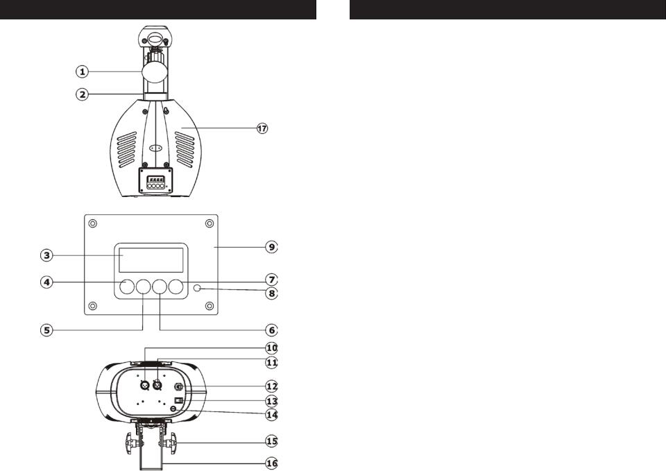
1. Mirror - This is a highly reflective surface mirror specifically designed to optimize and enhance beam output. Never use glass cleaners that contain ammonia to clean the surface of the mirror (such as Windex).
2.Lens Assembly - This high quality lens is a fully focusing. Focus the lens by manually turning the lens in a clockwise or counter-clock- wise direction until the desired effect is achieved.
3.Digital Display - This display shows the menu and operating functions that you can choose from.
4.Mode/Esc Button - This button is used to enter the main menu and submenus. It is also used to exit menus.
5.Up Button - This button is used to scroll forward when navigating through the system menu.
6.Down Button - This button is used to scroll backwards when navigating through the system menu.
7.Enter Button - This button is used to select and confirm a function in the system menu.
8.Microphone - This microphone receives external low frequencies to trigger the unit in Sound-Active mode. This microphone is designed to receive low frequency sounds only, tapping on the microphone and high pitch sounds may not trigger the unit.
9.Control Board
10.XLR DMX Input Jack - This jack is used to receive an incoming DMX signal or Master/Slave signal.
11.XLR Output Jack - This jack is used to transmit the incoming
DMX signal to another DMX fixture, or transmit a Master/Slave signal to the next Vizi Scan LED PRO in the chain. For best results in DMX or Master/Slave mode terminate this jack if it is the last unit in the chain. See “Terminator” on page 13.
12. Power Cord - This cord used to supply power to the unit. Never use this unit if the cord is broken or frayed. Never use this fixture if the ground prong has been removed or broken off. The ground prong is designed to reduce the risk of fire or electrical shock in the event the unit suffers from an internal short.
American DJ® - www.americandj.com - Vizi Scan LED PRO Instruction Manual Page 10
Vizi Scan LED PRO |
Controls and Functions |
13.Power Switch - This switches the power to the fixture “On” & “Off”.
14.Fuse Holder - This housing stores a 4 amp protective fuse. Never defeat the fuse, the fuse is designed to protect the electronics in the event of severe power fluctuations. Always be sure to replace the fuse
with an exact match as the one being replaced, unless otherwise told to do so by an authorized American DJ® service technician.
American DJ® - www.americandj.com - Vizi Scan LED PRO Instruction Manual Page 11
Vizi Scan LED PRO |
Set Up |
Power Supply: The American DJ® Vizi Scan LED PRO contains a electronic ballast, which will auto sense the voltage when it is plugged into the power source. With the electronic ballast you do not need to worry about wall voltage, this unit can be plugged in anywhere.
DMX-512: DMX is short for Digital Multiplex. This is a universal protocol used by most lighting and controller manufactures as a form of
communication between intelligent fixtures and |
controllers. A DMX |
||
controller sends |
DMX data instructions from the |
controller to the fix- |
|
ture. DMX data |
is sent |
as serial data that travels |
from fixture to fixture |
via the DATA “IN” and |
DATA “OUT” XLR terminals located on all DMX |
||
fixtures (most controllers only have a DATA “OUT” terminal).
DMX Linking: DMX is a language allowing all makes and models of different manufactures to be linked together and operate from a single controller, as long as all fixtures and the controller are DMX compliant. To ensure proper DMX data transmission, when using several DMX fixtures try to use the shortest cable path possible. The order in which fixtures are connected in a DMX line does not influence the DMX addressing. For example; a fixture assigned a DMX address of 1 may be placed anywhere in a DMX line, at the beginning, at the end, or anywhere in the middle. Therefore, the first fixture controlled by the controller could be the last fixture in the chain. When a fixture is assigned a DMX address of 1, the DMX controller knows to send DATA assigned to address 1 to that unit, no matter where it is located in the DMX chain.
Data Cable (DMX Cable) Requirements (For DMX and Master/Slave Operation): The Vizi Scan LED PRO can be controlled via DMX-512 protocol. The Vizi Scan LED PRO can be either a 12 or 14 DMX Chan-
nel unit. The DMX address is set |
electronically using |
the controls on |
||||
the front panel |
of the unit. Your unit and |
your DMX |
|
|||
controller require a |
approved DMX-512 110 Ohm |
|
||||
Data cable for |
data |
input and |
data |
output. We |
|
|
recommend Accu-Cable DMX cables. If |
you are |
|
||||
making your own cables, be sure to use standard |
|
|||||
110-120 Ohm |
shielded cable (This cable |
may be |
|
|||
purchased at |
almost all professional sound and |
|
||||
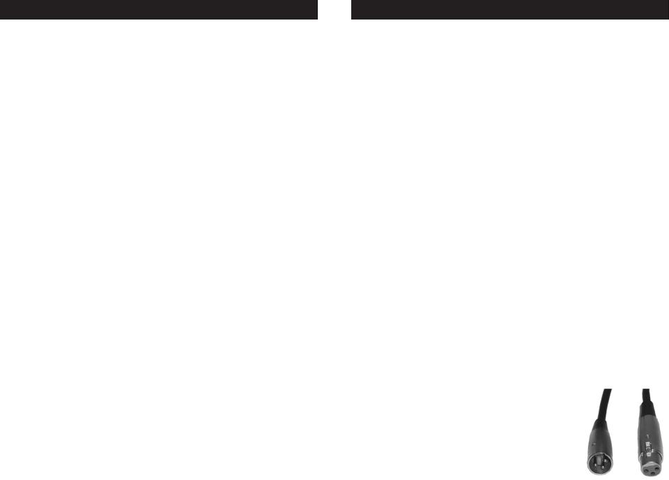
lighting stores). Your cables should be |
made with |
|
||||
a male and female XLR connector on either end of |
Figure 1 |
|||||
American DJ® - |
www.americandj.com - Vizi Scan LED PRO Instruction Manual Page 12 |
|||||
Vizi Scan LED PRO |
Set Up |
the cable. Also remember that DMX cable must be daisy chained and cannot be split.
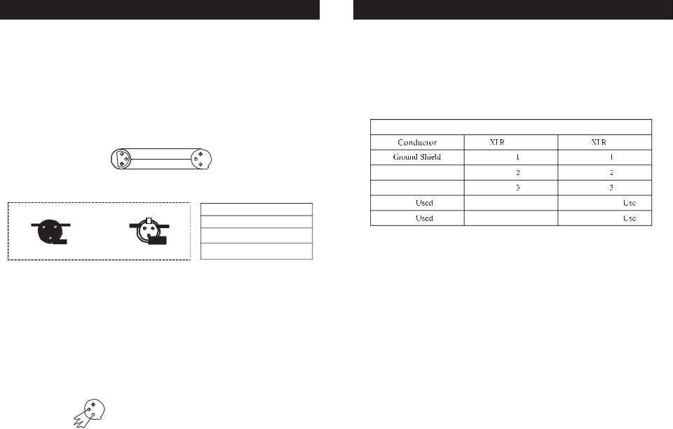
Notice: Be sure to follow figures two and three when making your own cables. Do not use the ground lug on the XLR connector. Do not connect the cable’s shield conductor to the ground lug or allow the shield conductor to come in contact with the XLR’s outer casing. Grounding the shield could cause a short circuit and erratic behavior.
|
|
COMMON |
|
|
DMX512 OUT |
1 |
DMX + |
1 |
DMX512 IN |
3 |
3 |
|
||
3-PIN XLR |
2 |
DMX - |
2 |
3-PIN XLR |
Figure 2
XLR Male Socket |
XLR Female Socket |
||
1 Ground |
2 Cold |
2 Cold |
1 Ground |
|
|||
|
3 Hot |
|
3 Hot |
Figure 3
 Pin
Pin 
Pin 1 =
Pin 2 = Data 
Pin 3 = Data True
Special Note: Line Termination. When longer runs of cable are used, you may need to use a terminator on the last unit to avoid erratic behavior. A terminator is a 90-120 ohm 1/4 watt resistor which is connected between pins 2 and 3 of a male XLR connector (DATA + and DATA -). This unit is inserted in the female XLR connector of the last unit in your daisy chain to terminate the line. Using a cable terminator (ADJ part number Z-DMX/T) will decrease the possibilities of erratic behavior.
|
Termination reduces signal errors and |
|
1 |
avoids signal transmission problems |
|
3 |
and interference. It is always advisable |
|
2 |
to connect a DMX terminal, (Resistance |
|
|
120 Ohm 1/4 W) between PIN 2 (DMX-) |
Figure 4 |
|
and PIN 3 (DMX +) of the last fixture. |
American DJ® - www.americandj.com - Vizi Scan LED PRO Instruction Manual Page 13
Vizi Scan LED PRO |
Set Up |
5-Pin XLR DMX Connectors. Some manufactures use 5-pin XLR connectors for DATA transmission in place of 3-pin. 5-pin XLR fixtures may be implemented in a 3-pin XLR DMX line. When inserting standard 5-pin XLR connectors in to a 3-pin line a cable adaptor must be used, these adaptors are readily available at most electric stores. The chart below details a proper cable conversion.
3-Pin XLR to 5-Pin XLR Conversion |
|
||
3-Pin |
Female (Out) |
5-Pin |
Male (In) |
|
Pin |
|
Pin |
Data Compliment (- signal) |
Pin |
|
Pin |
Data True (+ signal) |
Pin |
|
Pin |
Not |
|
Pin 4 - Do Not |
|
Not |
|
Pin 5 - Do Not |
|
American DJ® - www.americandj.com - Vizi Scan LED PRO Instruction Manual Page 14

Vizi Scan LED PRO |
System Menu |
1 |
ADDR |
AXXX |
A001 |
|
2 |
TEST |
T-01~T-XX |
||
|
|
RUN |
||
3 |
PLAY |
AUDI |
||
|
|
|||
|
|
AUTO |
||
|
|
ALL |
||
4 |
RESE |
SCAN |
||
COLR |
||||
|
|
|||
|
|
GOBO |
||
|
|
OTHR |
||
5 |
TIME |
LIFE |
||
CLMP |
||||
|
|
|||
6 |
RPAN |
ON/OFF |
||
7 |
RTLT |
ON/OFF |
||
8 |
FINE |
ON/OFF |
||
9 |
MIC |
M-XX M-70 |
||
|
|
VALU |
||
10 |
DISP |
D ON |
||
|
|
|||
|
|
FLIP |
||
|
|
LOCK |
||
|
|
RDMX |
||
|
|
SPOT |
||
|
|
DFSE |
||
11 |
SPEC |
FANS |
||
|
|
|||
|
|
HIbE |
||
|
|
VER |
||
|
|
ADJU |
||
|
|
SEPR |
||
|
|
STEP |
||
12 |
EDIT |
|
|
|
|
|
SCXX |
||
REC.
RUN
Default setting shaded.
MSTR/ALON
MSTR/ALON
Clos/Hold/Auto/Audi
0000~9999
D–XX D-00 (DXXX)
ON/OFF
ON/OFF
ON/OFF
ON/OFF
ON/OFF
ON/OFF
AUTO/HIGH/LOW OFF/1-99M 15M V1.0~V9.9
CODE CH01~CHXX AUTO IP01~IP07
S–01 ~S–48
C–01~C–XX
TIME
CEDT
RE.XX
ON/OFF
Indicate the staring DMX address A001 also is the setting for slave Automatically test the function
Runs fixture as “master” or “alone” for auto
Runs fixture as “master” or “alone” for audio
No DMX 
Reset all motors and returns fixture to home
Reset only motors for pan/tilt Reset only motors for colors
Reset only motors for gobo and rotation Reset other motors
Displays the total fixture running time Clear lamp running time
Reverses the pan movements Reverses the tilt movements Switch 16 bit/8 bit
Mic sensitivity
Display the DMX512 value of each channel
Display turn off after 2mins
This function will reverse the display 180
Key lock
Change DMX address via external controller
Lamp optimization
Resets all the fixture functions to default
Fan’s mode select |
|
|
|
||
Stand by mode |
|
|
|
|
|
Software version |
|
|
|
||
CXXX |
Fixture code *code is “C050” |
||||
XXXX(-128~127) |
Motor Fix |
|
|
|
|
|
Select program to be edit |
|
|||
|
Set |
the |
amount |
f |
your |
|
program |
|
|
|
|
XXX(0~255) |
Edit |
the |
channels |
of |
each |
scene |
|
|
|
|
|
|
|
|
|
|
|
T XXX(001~999) |
Time for each scene |
|
|
||
ON/OFF |
Edit program via controller |
||||
|
Auto Save |
|
|
|
|
|
Program test |
|
|
||
American DJ® - www.americandj.com - Vizi Scan LED PRO Instruction Manual Page 15
Vizi Scan LED PRO |
System Menu |
ADDRESS MENU -
AOO1 - A511 (Value) - This is where you set the DMX address of the unit.
TEST MENU -
T-01 - T-XX (Test) - Tests the functions of each channel. Note:
Some channels cannot be tested.
PLAY MENU -
RUN - Runs the unit as a “master” or in a stand-alone mode. The unit will run a internal program mode.
AUDI (Audio) - Runs the unit as a “master” or in a stand-alone, sound active mode.
AUTO - This is a precaution mode in case the DMX signal is lost. There are four settings to choose from:
• “Hold” - This is the default setting, which in case the signal is lost the fixture will “hold” at the last setting.
•“Close” - The fixture will return to its “home” standing.
•“Auto” - The fixture will go into Auto mode and run a pre-programmed show.
•“Audi” - The fixture will go into Sound Active mode.
RESE (RESET) MENU -
ALL - Resets all the motors in the unit.
SCAN - Resets the motors that control pan/tilt.
COLR (Color) - Resets the color motors.
GOBO - Resets the gobo motors.
OTHR - Resets all other motors.
TIME MENU -
LIFE - Displays the fixtures total running time.
American DJ® - www.americandj.com - Vizi Scan LED PRO Instruction Manual Page 16
 Loading...