


Inno Pocket Spot
User Instructions
Rev. 10/14
©2014 ADJ Products, LLC all rights reserved. Information,
specications, diagrams, images, and instructions herein are
subject to change without notice. ADJ Products, LLC logo and
identifying product names and numbers herein are trademarks
of ADJ Products, LLC. Copyright protection claimed includes all
forms and matters of copyrightable materials and information
now allowed by statutory or judicial law or hereinafter granted.
Product names used in this document may be trademarks or
registered trademarks of their respective companies and are
hereby acknowledged. All non-ADJ Products, LLC brands and
product names are trademarks or registered trademarks of their
respective companies.
ADJ Products, LLC and all aliated companies hereby dis-
claim any and all liabilities for property, equipment, building,
and electrical damages, injuries to any persons, and direct or
indirect economic loss associated with the use or reliance of
any information contained within this document, and/or as a
result of the improper, unsafe, unsucient and negligent as-
sembly, installation, rigging, and operation of this product.
Europe Energy Saving Notice
Energy Saving Matters (EuP 2009/125/EC)
Saving electric energy is a key to help protecting the enviroment.
Please turn o all electrical products when they are not in use. To
avoid power consumption in idle mode, disconnect all electrical
equipment from power when not in use. Thank you!
INNO POCKET SPOT

ADJ Products, LLC - www.adj.com - Inno Pocket Spot Instruction Manual Page 3ADJ Products, LLC - www.adj.com - Inno Pocket Spot Instruction Manual Page 2
• DMX-512 Protocol Compatible (9 DMX Channels or 11 Channels)
• 7 Colors + White
• Fixed Gobo Wheel with 7 Gobos + Spot
• 3 Operating Modes - Sound Active, Show Mode, & DMX Control
• Internal Microphone
• Digital Display for Address and Function Setting
• 4 Preprogrammed Shows
• UC-IR Compatiable (Not Included)
Inno Pocket Spot Features
Caution! There are no user serviceable parts inside this unit. Do not
attempt any repairs yourself, doing so will void your manufactures
warranty. In the unlikely event your unit may require service please
contact ADJ Products, LLC.
During operation the housing may become extremely hot. Avoid
touching the unit with bare hands while in use.
ADJ Products, LLC will not accept any liability for any resulting dam-
ages caused by the non-observance of this manual or any unauthor-
ized modication to this unit.
Inno Pocket Spot Handling Precautions
Inno Pocket Spot Warranty Registration
The Inno Pocket Spot carries a 2 year (730 days) limited warranty.
Please fill out the enclosed warranty card to validate your purchase
and warranty. You may also register your product online at www. adj-
products.com. All returned service items whether under warranty or
not, must be freight pre-paid and accompany a return authorization
(R.A.) number. If the unit is under warranty you must provide a copy
of your proof of purchase invoice. Please contact ADJ Products, LLC
customer support for a R.A. number.
To optimize the performance of this product, please read these
operating instructions carefully to familiarize yourself with the basic
operations of this unit. These instructions contain important safety
information regarding the use and maintenance of this unit. Please
keep this manual with the unit, for future reference.
Inno Pocket Spot General Instructions
Inno Pocket Spot General Information
Unpacking: Thank you for purchasing the Inno Pocket Spot by ADJ
Products, LLC. Every Inno Pocket Spot has been thoroughly tested and
has been shipped in perfect operating condition. Carefully check the
shipping carton for damage that may have occurred during shipping.
If the carton appears to be damaged, carefully inspect your xture for
any damage and be sure all equipment necessary to operate the unit
has arrived intact. In the event damage has been found or parts are
missing, please contact our toll free customer support number for fur-
ther instructions. Please do not return this unit to your dealer without
contacting customer support rst.
Introduction: The Inno Pocket Spot is a DMX intelligent, moving
head, mini LED fixture. The Inno Pocket Spot can operate as a stand
alone fixture or in a Master/Slave configuration. The Inno Pocket Spot
has three operating modes; a sound active, show mode, DMX con-
trolled. This fixture is suitable for theaters, studios, retail stores, and
other similar locations. For best results use fog or special effects smoke
to enhance the beams projections.
Customer Support: ADJ Products, LLC provides a toll free cus-
tomer support line, to provide help and to answer any question should
you encounter problems during your set up or initial operation. You
may also visit us on the web at www.adj.com for any comments or
suggestions. Service Hours are Monday through Friday 8:00 a.m. to
4:30 p.m. Pacic Standard Time.
Voice: (800) 322-6337
Fax: (323) 582-2941
E-mail: support@americandj.com
Warning! To prevent or reduce the risk of electrical shock or re, do
not expose this unit to rain or moisture.
Warning! This may cause severe eye damage. Avoid looking directly
into the light source at all times!
For Your Own Personal Safety, Please Read and Understand This
Manual Completely Before You Attempt To Install Or Operate
This Unit!
• To reduce the risk of electrical shock or re, do not expose this unit
rain or moisture
• Do not spill water or other liquids into or on to your unit.
• Be sure that the local power outlet match that of the required volt-
age for your unit.
• Do not attempt to operate this unit if the power cord has been
frayed or broken.
• Do not attempt to remove or break o the ground prong from
the electrical cord. This prong is used to reduce the risk of electrical
shock and re in case of an internal short.
• Disconnect from main power before making any type of connection.
• Do not remove the cover under any conditions. There are no user
serviceable parts inside.
• Never operate this unit when it’s cover is removed.
• Always be sure to mount this unit in an area that will allow proper
ventilation. Allow about 6” (15cm) between this device and a wall.
• Do not attempt to operate this unit, if it becomes damaged.
• This unit is intended for indoor use only, use of this product out-
doors voids all warranties.
• Always mount this unit in safe and stable matter.
• Power-supply cords should be routed so that they are not likely to
be walked on or pinched by items placed upon or against them,
paying particular attention to cords at plugs, convenience recep-
tacles, and the point where they exit from the appliance.
• Cleaning -The fixture should be cleaned only as recommended by
the manufacturer. See page 25 for cleaning details.
• Heat -This fixture should be situated away from heat sources such
as radiators, heat registers, stoves, or other appliances (including
amplifiers) that produce heat.
• The fixture should be serviced by qualified service personnel when:
A. Objects have fallen, or liquid has been spilled into the appliance.
B. The appliance has been exposed to rain or water.
C. The appliance does not appear to operate normally or exhibits
a marked change in performance.
Inno Pocket Spot Safety Precautions
ADJ Products, LLC - www.adj.com - Inno Pocket Spot Instruction Manual Page 5ADJ Products, LLC - www.adj.com - Inno Pocket Spot Instruction Manual Page 4
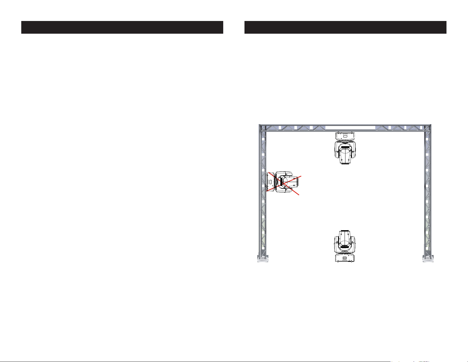
The Inno Pocket Spot is fully operational in two dierent mounting
positions, hanging upside-down from a ceiling or set on a at level
surface. To avoid internal damage to the unit, never mount the unit on
its side as illustrated above. Be sure this xture is kept at least 0.5m
away from any ammable materials (decoration etc.). Always use
and install the supplied safety cable as a safety measure to prevent
accidental damage and/or injury in the event the clamp fails (see next
page).
When installing the unit, the trussing or area of installation must be
able to hold 10 times the weight without any deformation. When
installing the unit must be secured with a secondary safety attach-
ment, e.g. and appropriate safety cable. Never stand directly below
the unit when mounting, removing, or servicing the unit.
Overhead mounting requires extensive experience, including calculat-
ing working load limits, installation material being used, and perodic
safety inspection of all installation material and unit. If you lack these
qualications, do not attempt the installation yourself.
The installaiton should be checked by a skilled person once a year.
Inno Pocket Spot Mounting
ADJ Products, LLC - www.adj.com - Inno Pocket Spot Instruction Manual Page 6 ADJ Products, LLC - www.adj.com - Inno Pocket Spot Instruction Manual Page 7
Power Supply: The ADJ Inno Pocket Spot contains a automatic volt-
age switch, which will auto sense the voltage when it is plugged into
the power source. With this switch there is no need to worry about the
correct power voltage, this unit can be plugged in anywhere.
DMX-512: DMX is short for Digital Multiplex. This is a universal pro-
tocol used by most lighting and controller manufactures as a form of
communication between intelligent fixtures and controllers. A DMX
controller sends DMX data instructions from the controller to the fix-
ture. DMX data is sent as serial data that travels from fixture to fixture
via the DATA “IN” and DATA “OUT” XLR terminals located on all DMX
fixtures (most controllers only have a DATA “OUT” terminal).
DMX Linking: DMX is a language allowing all makes and models
of dierent manufactures to be linked together and operate from a
single controller, as long as all xtures and the controller are DMX
compliant. To ensure proper DMX data transmission, when using
several DMX fixtures try to use the shortest cable path possible. The
order in which fixtures are connected in a DMX line does not influence
the DMX addressing. For example; a fixture assigned a DMX address
of 1 may be placed anywhere in a DMX line, at the beginning, at the
end, or anywhere in the middle. Therefore, the first fixture controlled
by the controller could be the last fixture in the chain. When a fixture
is assigned a DMX address of 1, the DMX controller knows to send
DATA assigned to address 1 to that unit, no matter where it is located
in the DMX chain.
Data Cable (DMX Cable) Requirements (For DMX and Master/Slave
Operation): The Inno Pocket Spot can be controlled via DMX-512 pro-
tocol. The Inno Pocket Spot two DMX channel modes; 9 channel mode
& 11 channel mode. The DMX address is set elec-
tronically using the controls on the front panel of
the unit. Your unit and your DMX controller require
a approved DMX-512 110 Ohm Data cable for data
input and data output (Figure 1). We recommend
Accu-Cable DMX cables. If you are making your
own cables, be sure to use standard 110-120 Ohm
shielded cable (This cable may be purchased at
almost all professional sound and lighting stores).
Inno Pocket Spot DMX Set Up
Figure 1
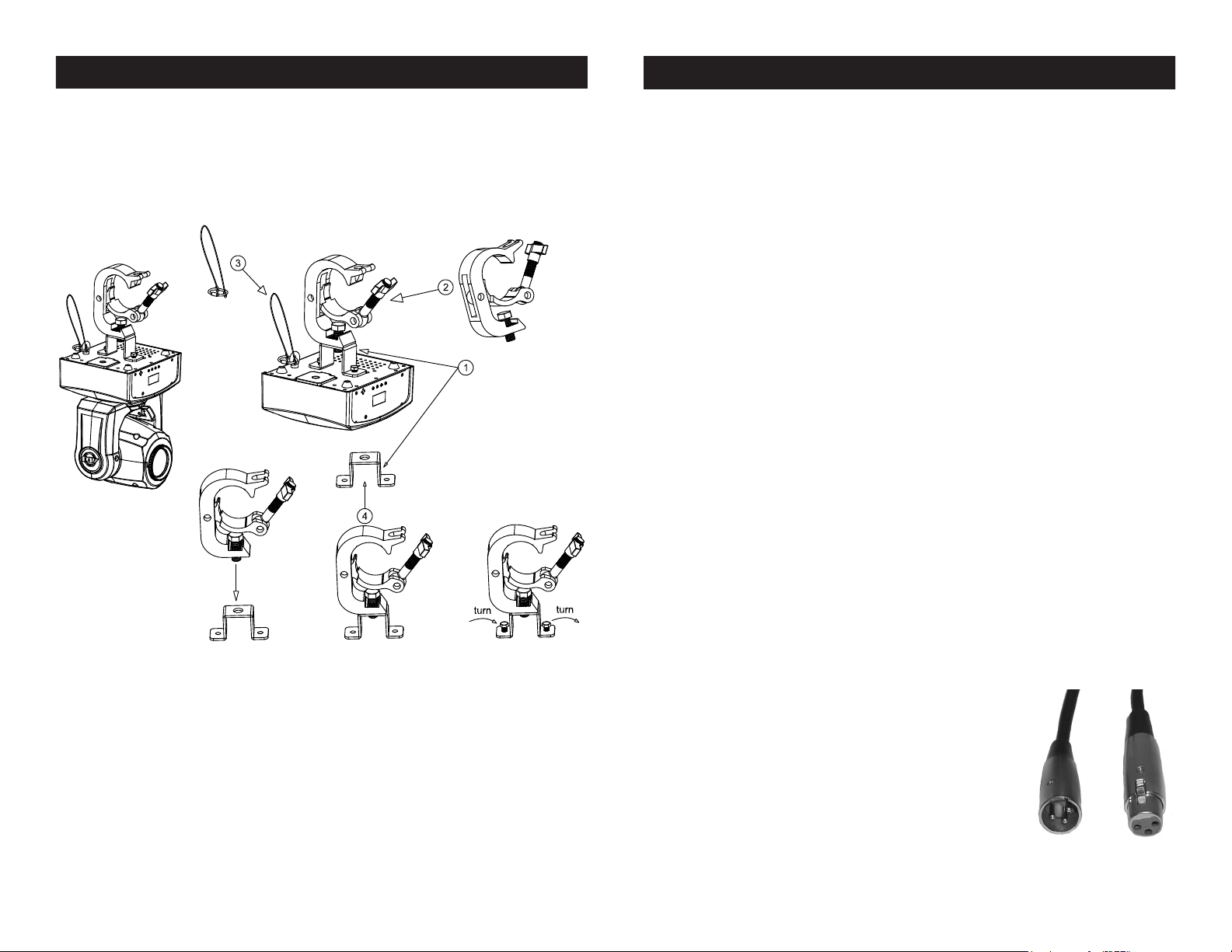
Screw one clamp via a M12 screw and nut to the included
bracket. Attach the bracket using the included screws to the
bottom of the Inno Pocket Spot. Attach the eyehole screw to
the bottom of the base and pull the safety-cable through the
screw and over the trussing system or a safe xation spot.
Insert the end in the carabine and tighten the safety screw.
NOTICE: The suitable enviromental temperature for this light-
ing xture is between -25˚ C to 45˚ C. Do not place this lighting
xture in an enviroment where the temperatures are under or
above the temperatures stated above. This will allow the xture
to run at its best and help prolong the xture life.
Inno Pocket Spot Mounting
ADJ Products, LLC - www.adj.com - Inno Pocket Spot Instruction Manual Page 9ADJ Products, LLC - www.adj.com - Inno Pocket Spot Instruction Manual Page 8
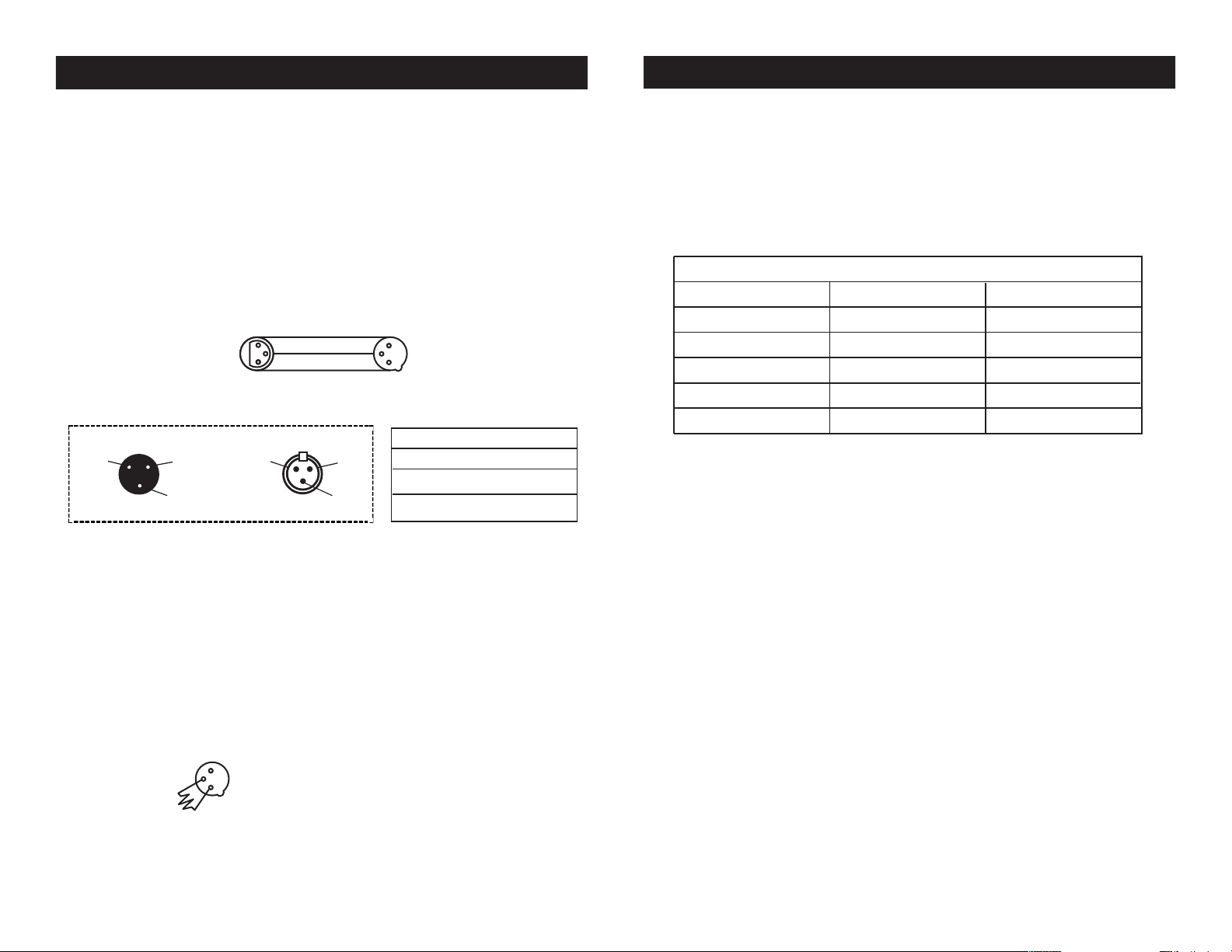
5-Pin XLR DMX Connectors.
Some manufactures use 5-pin DMX-
512 data cables for DATA transmission in place of 3-pin. 5-pin DMX
xtures may be implemented in a 3-pin DMX line. When inserting stan-
dard 5-pin data cables in to a 3-pin line a cable adaptor must be used,
these adaptors are readily available at most electric stores. The chart
below details a proper cable conversion.
Conductor 5-Pin XLR Male (In)3-Pin XLR Female (Out)
Pin 1
Pin 5 - Do Not Use
Pin 4 - Do Not Use
Pin 3
Pin 2
Pin 1
Pin 3
Pin 2
Not Used
Not Used
Data True (+ signal)
Data Compliment (- signal)
Ground/Shield
3-Pin XLR to 5-Pin XLR Conversion
Inno Pocket Spot DMX Set Up
Your cables should be made with a male and female XLR connector on
either end of the cable. Also remember that DMX cable must be daisy
chained and cannot be split.
Inno Pocket Spot DMX Set Up
Notice: Be sure to follow gures two and three when making your own
cables. Do not use the ground lug on the XLR connector. Do not con-
nect the cable’s shield conductor to the ground lug or allow the shield
conductor to come in contact with the XLR’s outer casing. Grounding
the shield could cause a short circuit and erratic behavior.
DMX512 IN
3-PIN XLR
REMOTE
CONTROL
INPUT
POWER
INPUT OUTPUT
SOUND
REMOTE
CONTROL
INPUT
POWER
INPUT OUTPUT
SOUND
REMOTE
CONTROL
INPUT
POWER
INPUT OUTPUT
DMX512
DMX+,DMX-,COMMON
1
2
3
Termination reduces signal errors and
avoids signal transmission problems
and interference. It is always advisable
to connect a DMX terminal, (Resistance
120 Ohm 1/4 W) between PIN 2 (DMX-)
and PIN 3 (DMX +) of the last fixture.
1
2
3
1
2
3
DMX +
DMX -
COMMON
DMX512 OUT
3-PIN XLR
Figure 2
Figure 3
1 Ground
1 Ground
XLR Male Socket
XLR Pin Conguration
3 Hot
2 Cold
2 Cold
3 Hot
XLR Female Socket
Pin 3 = Data True (positive)
Pin 2 = Data Compliment (negative)
Pin 1 = Ground
Special Note: Line Termination.
When longer runs of cable are
used, you may need to use a terminator on the last unit to avoid erratic
behavior. A terminator is a 110-120 ohm 1/4 watt resistor which is con-
nected between pins 2 and 3 of a male XLR connector (DATA + and
DATA -). This unit is inserted in the female XLR connector of the last
unit in your daisy chain to terminate the line. Using a cable terminator
(ADJ part number Z-DMX/T) will decrease the possibilities of erratic
behavior.
POWER
SOUND
REMOTE
CONTROL
INPUT
POWER
INPUT OUTPUT
1
2
3
Termination reduces signal errors and
avoids signal transmission problems
and interference. It is always advisable
to connect a DMX terminal, (Resistance
120 Ohm 1/4 W) between PIN 2 (DMX-)
and PIN 3 (DMX +) of the last fixture.
Figure 4
 Loading...