


STAGE SETTER-8
User Instructions
|
Elation Professional |
|
4295 Charter Street |
|
Los Angeles Ca. 90058 |
Rev. 2/05 |
www.elationlighting.com |
Stage Setter 8™ |
Introduction |
Introduction:
Thank you for purchasing the Elation Professional® Stage Setter 8.™ To optimize the performance of this product, please read these operating instructions carefully to familiarize yourself with the basic operations of this unit. The Elation® Stage Setter 8™ is a unique 16 channel DMX controller. This unit has been tested at the factory before being shipped to you, there is no assembly required.
Customer Support:
Elation® provides a toll free customer support line, to provide set up help and to answer any question should you encounter problems during your set up or initial operation. You may also visit us on the web at www.elationlighting.com for any comments or suggestions.
Service Hours are Monday through Friday 10:00 a.m. to 5:00 p.m. Pacific Standard Time.
Voice: |
(323) 582-3322 |
Fax: |
(323) 582-2610 |
E-mail: |
support@elationlighting.com |
Warning! To prevent or reduce the risk of electrical shock or fire, do not expose this unit to rain or moisture.
Caution! There are no user serviceable parts inside this unit. Do not attempt any repairs yourself, doing so will void your manufactures warranty. In the unlikely event your unit may require service please contact your nearest Elation® dealer.
Do not discard this cartoon in the trash. Please recycle when ever possible.
Upon unpacking, carefully inspect your unit for any damage that may have occurred during shipping. If damage may have occurred, do not plug the unit in, please contact your dealer as soon as possible.
Elation Professional® www.elationlighting.com Stage Setter 8™ Instruction Manual Page 2

Stage Setter 8™ |
Contents |
Introduction.......................................................................... |
2 |
Features.............................................................................. |
4 |
Overview............................................................................. |
5 |
Set-Up............................................................................... |
6 |
Frt Panel Controls and Functions................................................. |
8 |
Rear Panel Controls and Functions............................................ |
13 |
General Operation: |
|
Operating Modes.................................................. .................... |
15 |
Master Scenes........................................................................... |
15 |
Flash Scenes............................................................................. |
16 |
Programming Chase Patterns: |
|
2x8 and 8x8 Modes.................................................................... |
17 |
1x16 Mode................................................................................. |
18 |
MIDI Operation.......................................................................... |
19 |
LCD Value Change.................................................................... |
20 |
Memory Dump........................................................................... |
21 |
Technical Specifications............................................................ |
22 |
Warranty...................................................................... |
23 |
Improvements and changes in specifications and design to this manual and unit may be made at any time without prior notice.
Stage Setter 8™ |
Introduction |
FEATURES:
Stage Setter 8™ features include:
•2 x 3-pin XLR OUT
•Three different operating modes: 2 x 8, 8 x 8, and 1 x 16
•12 pattern option: 4 built in and 8 user programmable
•32 steps (scenes) per a program
•MIDI compatible
•Fog machine output button
•Scene crossfader
•Tap SYNC button
•8 Bump Buttons
•Back up memory protection
•Full functional, 4 digit LCD display
Elation Professional® - www.elationlighting.com - Stage Setter 8™ Instruction Manual Page 3 |
Elation Professional® - www.elationlighting.com - Stage Setter 8™ Instruction Manual Page 4 |
Stage Setter 8™ |
Introduction |
WARNINGS:
•Do not spill water or other liquids in to or on to your unit.
•Be sure that the local power outlet match that of the required voltage for your unit.
•Do not attempt to operate this unit if the power cord has been frayed or broken. Please route your power cord out of the way of foot traffic.
•Do not attempt to remove or break off the ground prong from the electrical cord. This prong is used to reduce the risk of electrical shock and fire in case of an internal short.
•Disconnect from main power before making any type of connection.
•Do not remove the top cover under any conditions. There are no user serviceable parts inside.
•Disconnect the unit’s main power when left unused for long periods of time.
•Never plug this unit in to a dimmer pack
•Always be sure to mount this unit in an area that will allow proper ventilation. Allow about 6” (15cm) between this device and a wall.
•Do not attempt to operate this unit, if it becomes damaged in any way.
•Never operate this unit when it’s cover is removed.
•To reduce the risk of electrical shock or fire, do not expose this unit rain or moisture
•This unit is intended for indoor use only, use of this product outdoors voids all warranties.
•During long periods of non-use, disconnect the unit’s main power.
•Always mount this unit in safe and stable matter.
Stage Setter 8™ |
Set Up |
Unpacking:
Every Stage Setter 8™ has been thoroughly tested and has been shipped in perfect operating order. Carefully check the shipping carton for damage that may have occurred during shipping. If the carton appears to be damaged, carefully inspect your fixture for any damage. In the case damage has been found please contact our toll free customer support number for further instructions.
Power Supply:
Before plugging your unit in be sure the source voltage in your area matches the required voltage for your Elation® Stage Setter 8.™ The Elation® Stage Setter 8™ is available in a 115v and 230v version. Because line voltage may vary from venue to venue, you should be sure to plug your unit into a matching wall outlet before attempting to operate you controller.
Data Cable (DMX Cable) Requirements:
Your controller and packs require a standard 3-pin XLR connector for DMX data input and DMX data output (Figure 1). If you are making your own cables be sure to use standard two conductor shielded cable (This cable may be purchased at almost all pro sound and lighting stores). Your cables should be made with a male and female XLR connector on either end of the cable. Also remember that DMX cable must be daisy chained and can not be “Y”ed or split.
Notice: Do not use the ground lug on the XLR connector. Do not connect the cable’s shield conductor to the ground lug or allow the shield conductor to come in contact with the XLR’s outer casing. Grounding the shield could cause a short circuit and erratic behavior.
Notice: Be sure to follow figures two and three when making your own cables.
|
|
COMMON |
|
|
|
DMX512 OUT |
1 |
DMX + |
1 |
DMX512 IN |
|
CONTROLLER |
|||||
3 |
3 |
|
CONNECTOR |
||
CONNECTOR |
|
||||
2 |
DMX - |
2 |
3 PIN |
||
3 PIN |
|||||
|
|
|
|
Figure 2
Elation Professional® - www.elationlighting.com - Stage Setter 8™ Instruction Manual Page 5 |
Elation Professional® - www.elationlighting.com - Stage Setter 8™ Instruction Manual Page 6 |

Stage Setter 8™ |
Set Up |
XLR Male Socket |
XLR Female Socket |
XLR Pin Configuration |
||
1 Ground |
2 Cold |
2 Cold |
1 Ground |
Pin 1 = Shield |
|
||||
|
|
|
|
|
|
|
|
|
Pin 2 = Data Compliment (negative) |
|
3 Hot |
|
3 Hot |
Pin 3 = Data True (positive) |
|
|
|
|
|
Figure 3
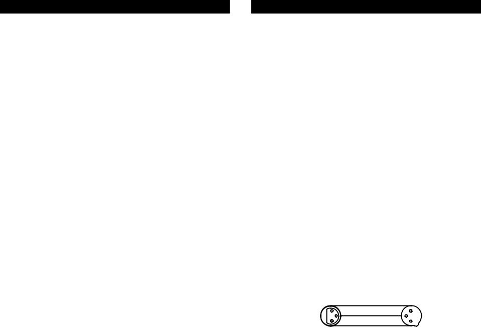
Special Note: Line Termination.
When longer runs of cable are used, you may need to use a terminator on the last unit to avoid erratic behavior. A terminator is a 90-120 ohm 1/4 watt resistor which is connected between pins 2 and 3 of a male XLR connector (DATA + and DATA -). This unit is inserted in the female XLR connector of the last unit in your daisy chain to terminate the line. Using a cable terminator will decrease the possibilities of erratic behavior.
|
Termination reduces signal errors and |
1 |
avoids signal transmission problems |
3 |
and interference. It is always advisable |
2to connect a DMX terminal, (Resistance 120 Ohm 1/4 W) between PIN 2 (DMX-) and PIN 3 (DMX +) of the last fixture.
Figure 4
Stage Setter 8™ |
Controls and Functions |
Front Panel
1 |
2 |
|
3 |
4 |
5 |
6 |
7 |
|
8 |
9 |
10 |
11 |
12 |
13 |
|
14 |
15 |
16 |
17 |
Front Panel - Controls and Functions
1. Channel LEDs (1-8):
These 8 LEDs detail the current intensity for channel sliders 1-8. The more you raise the channel slider the higher the output. The LED indicators will directly reflect the changes in slider level.
2. Scene X - Channel Faders 1-8:
These 8 sliders are used to control the intensities of channel 1-8. The overall intensity of channel faders 1-8 is controlled by the X Crossfader
(5).
Elation Professional® - www.elationlighting.com - Stage Setter 8™ Instruction Manual Page 7 |
Elation Profesional® - www.elationlighting.com - Stage Setter 8™ Instruction Manual Page 8 |
 Loading...