

Page 1
Adept SmartVision MX
User’s Guide
Page 2

Page 3
Adept SmartVision MX
User's Guide
P/N: 14362-000 Rev. A
December, 2014
5960 Inglewood Drive • Pleasanton, CA 94588 • USA • Phone 925.245.3400 • Fax 925.960.0452
Revierstraße 5 • 44227 Dortmund • Germany • Phone +49.231.75.89.40 • Fax +49.231.75.89.450
Block 5000 Ang Mo Kio Avenue 5 • #05-12 Techplace II • Singapore 569870 • Phone +65.6755-2258 • Fax +65.6755-0598
Page 4

Copyright Notice
The information contained herein is the property of Adept Technology, Inc., and shall not be
reproduced in whole or in part without prior written approval of Adept Technology, Inc. The
information herein is subject to change without notice and should not be construed as a commitment by Adept Technology, Inc. The documentation is periodically reviewed and revised.
Adept Technology, Inc., assumes no responsibility for any errors or omissions in the documentation. Critical evaluation of the documentation by the user is welcomed. Your comments
assist us in preparation of future documentation. Please submit your comments to: tech-
pubs@adept.com.
Copyright 2014 by Adept Technology, Inc. All rights reserved.
Adept, the Adept logo, the Adept Technology logo, AdeptVision, AIM, Blox, Bloxview,
FireBlox, Fireview, Meta Controls, MetaControls, Metawire, Motivity, Soft Machines, and
Visual Machines are registered trademarks of Adept Technology, Inc.
Brain on Board is a registered trademark of Adept Technology, Inc. in Germany.
ACE PackXpert, Adept ACE, Adept Enterprise Manager, Adept Lynx, AdeptSight, Adept
SmartController EX, Adept SmartVision MX, eV+, MobileEyes, MobilePlanner, SetNetGo, and
V+ are trademarks of Adept Technology, Inc.
Any trademarks from other companies used in this publication
are the property of those respective companies.
Created in the United States of America
Adept SmartVision MX User’s Guide, Rev. A
Page 4 of 34
Page 5

Table of Contents
Chapter 1: Introduction 7
1.1 Product Description
Features 7
What Comes with an Adept SmartVision MX? 8
What Doesn’t Come with an Adept SmartVision MX? 10
1.2 Warnings, Cautions, and Notes
1.3 Manufacturer’s Declaration
1.4 How Can I Get Help?
Related Manuals 11
Adept Document Library 12
10
11
11
Chapter 2: Installation 13
2.1 Inspecting
2.2 Transport and Storage
2.3 Mounting the SmartVision MX
Space Around the Chassis 13
Desk-top Mounting 13
Stack Mounting 14
2.4 Connecting Power
External Power Supply 16
Installing 24 VDC Connector 17
Connecting to a SmartController 18
2.5 Connecting Display, Keyboard, and Mouse
13
13
13
16
19
7
Chapter 3: Connectors and Indicators 21
Camera Side 21
Power/IO Side 22
3.1 Ethernet Ports
3.2 USB Ports
3.3 DVI- Ports
3.4 I/O Connections
3.5 Audio and Serial Ports
22
23
23
23
23
Chapter 4: Operation 25
4.1 Operating Environment
4.2 Turning Power ON and OFF
Adept SmartVision MX User’s Guide, Rev. A
Page 5 of 34
25
25
Page 6

Table of Contents
4.3 Checking the Licenses on the Dongle
25
Chapter 5: Technical Specifications 27
5.1 Processing Specifications
5.2 Environmental Specifications
5.3 Power Requirements
5.4 Dimensions
5.5 Connections
27
27
27
27
28
Chapter 6: Options 31
6.1 License Options
6.2 Mounting
31
31
Adept SmartVision MX User’s Guide, Rev. A
Page 6 of 34
Page 7
1.1 Product Description
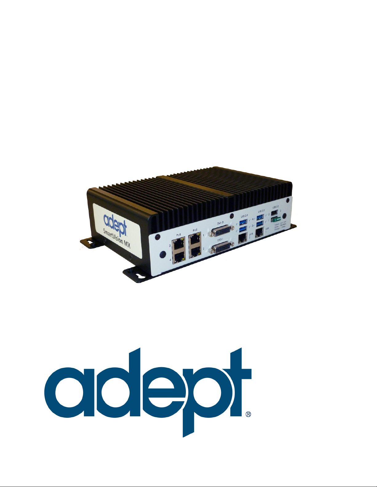
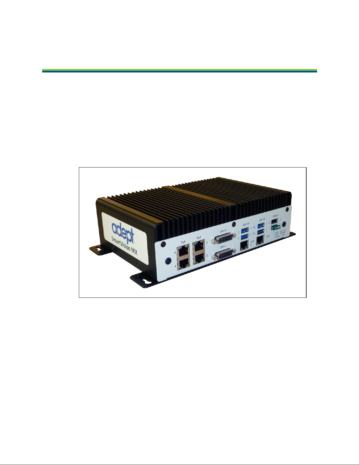
The Adept SmartVision MX™ is a Windows®7 Embedded industrial PC designed to run
Adept’s ACE software. It is compatible with Adept’s SmartController line of products, or can
be used with Adept robots that don’t use a SmartController.
For inspection applications, the Adept SmartVision MX industrial PC is designed to be a
“plug-and-play” vision system. Using a USB or GigE camera, along with Adept’s PC-based vision software, the unit is a complete industrial vision solution.
When used with a SmartController, the Adept SmartVision MX provides expanded vision processing power for vision-guided robotics or inspection.
Chapter 1: Introduction
Figure 1-1. The Adept SmartVision MX Vision Processor
Features
The Adept SmartVision MX provides the following features:
l
Compatibility with Adept’s SmartController line of products
l
Intel PC platform, with Core i7 processor
l
Windows 7 Embedded OS
l
Ports for both Gigabit and USB 3.0 cameras
Four Gigabit ports provide Power over Ethernet.
l
Standard Gigabit LAN
Adept SmartVision MX User’s Guide, Rev. A
Page 7 of 34
Page 8

Chapter 1: Introduction
l
Standard RS-232 interface
l
Both DVI-D and DVI-I ports
l
USB ports can support a keyboard and mouse, for standalone operation
l
DVI-D or DVI-I ports can support a monitor, for standalone operation
What Comes with an Adept SmartVision MX?
Hardware
The Adept SmartVision MX includes:
l
Intel®Core i7
l
8 GB DDR3 memory
l
64 GB mSATASSDdrive
The drive is partitioned into a C: drive and a D: drive. By default, the C: drive uses a
file-based write filter, to protect the Windows operating system and Adept ACE software. Adept recommends that you leave this write filter enabled for C: in normal use.
Because the OS and Adept ACE software are on C:, you should be very cautious about
using C: for any other purpose, particularly for other applications.
l
Matching connector for VDC input power
l
A USB license dongle, which enables licenses for one of the following:
o
AdeptSight software, 2 camera support
o
ACE PackXpert, 1 controller support
o
ACE PackXpert with AdeptSight software, 2 camera and 1 controller support
o
Any additional camera or controller licenses that you purchased
o
Other licenses can be purchased to increase the number of cameras and controllers supported.
Adept SmartVision MX User’s Guide, Rev. A
Page 8 of 34
Page 9
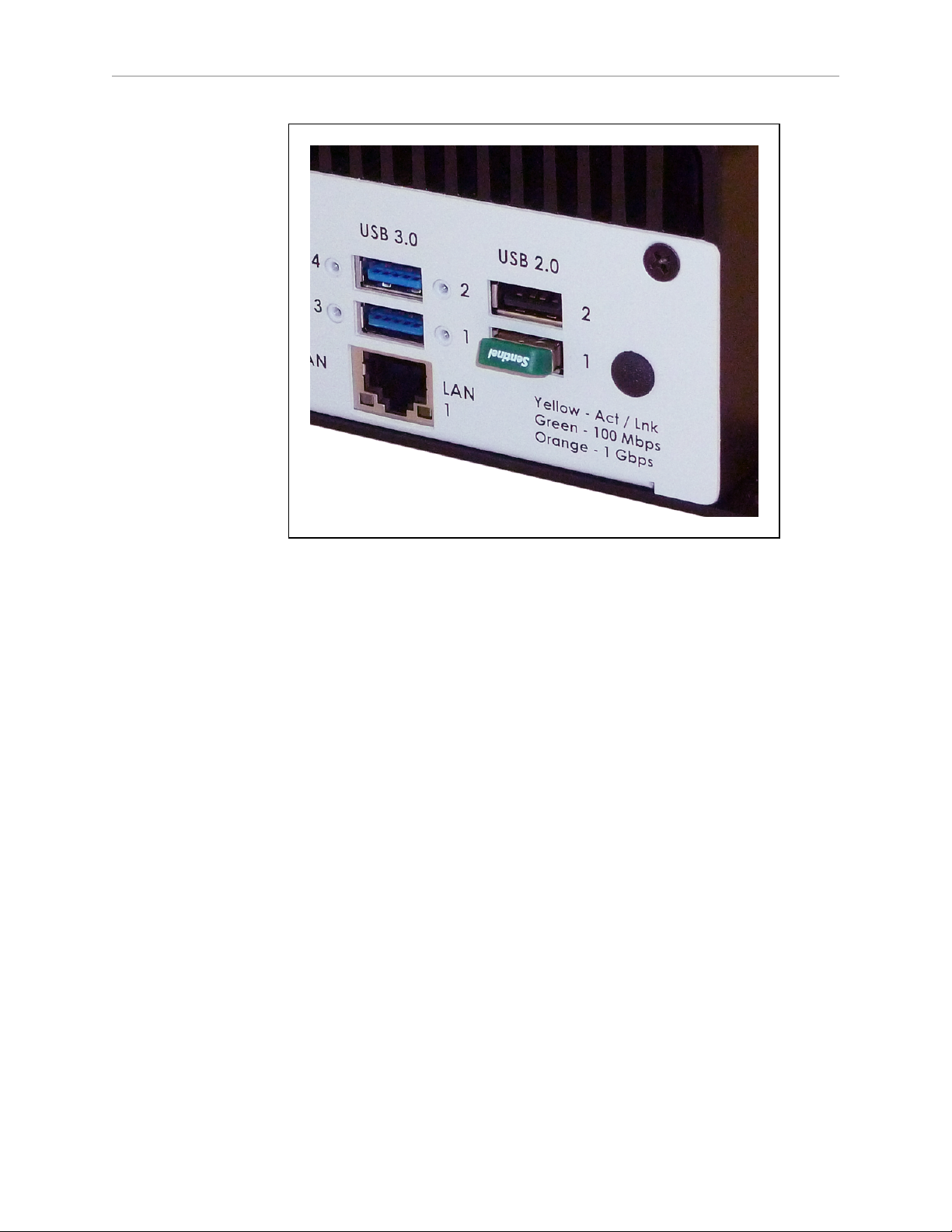
Chapter 1: Introduction
Figure 1-2. USB License Dongle in USB 2.0 Port 1
An Adept SmartVision MX can support a total of eight cameras and four controllers.
NOTE: If you are going to use an Adept SmartVision MX industrial PC with
AdeptSight, but without ACE PackXpert, the Adept controller needs to have a
motion license.
Software
The following software is pre-loaded on the hard drive:
l
Windows®7 Embedded
l
Adept ACE
l
AdeptSight 3 (Adept ACE-based vision software)
l
Drivers for Basler ACEcameras (USB and GigE)
The Adept SmartVision MX is designed to run Adept ACE software. Adept does not support
applications other than Adept ACE.
Options
For details on options, see Options on page 31.
l
Extended licenses, enabled on the USB license dongle
l
Stack-mounting brackets
Adept SmartVision MX User’s Guide, Rev. A
Page 9 of 34
Page 10
Chapter 1: Introduction
What Doesn’t Come with an Adept SmartVision MX?
l
24 VDC power supply to power the SmartVision MX industrial PC (see External Power
Supply on page 16).
If you are using the Adept SmartVision MX with a SmartController, you can generally
use 24 VDC power from the SmartController to power the Adept SmartVision MX. See
Connecting to a SmartController on page 18.
l
Cameras and camera cables
l
Keyboard, mouse, and monitor
These should be user-supplied, so you can run the Adept ACE and AdeptSight applications, and well as control shutting down the industrial PC.
l
If power interruption is a concern, a UPS is recommended. Contact Adept Customer Service for more information.
1.2 Warnings, Cautions, and Notes
There are five levels of special alert notation that are used in Adept manuals. In descending
order of importance, they are:
DANGER:This indicates an imminently hazardous electrical situation
which, if not avoided, will result in death or serious injury.
DANGER:This indicates an imminently hazardous situation which, if
not avoided, will result in death or serious injury.
WARNING:This indicates a potentially hazardous electrical situation
which, if not avoided, could result in serious injury or major damage
to the equipment.
WARNING:This indicates a potentially hazardous situation which, if
not avoided, could result in serious injury or major damage to the
equipment.
Adept SmartVision MX User’s Guide, Rev. A
Page 10 of 34
Page 11

Chapter 1: Introduction
CAUTION:This indicates a situation which, if not avoided, could result
in damage to the equipment.
NOTE:Notes provide supplementary information, emphasize a point or procedure,
or give a tip for easier operation.
1.3 Manufacturer’s Declaration
The Manufacturer’s Declaration of Incorporation and Conformity for the SmartVision MX can
be found on the Adept website, in the Download Center of the Support section.
http://www.adept.com/support/downloads/file-search
NOTE:The Download Center requires that you are logged in for access. If you are
not logged in, you will be redirected to the Adept website Login page.
1.
From the Download Types drop-down list, select Manufacturer Declarations.
2.
From the Product drop-down list, select the product category.
3.
Click Begin Search.
The list of available documents is shown in the Search Results area, which opens at the
bottom of the page. You may need to scroll down to see it.
4.
Use the Description column to locate the document for your SmartVision MX, and then
click the corresponding Download ID number to access the Download Details page.
5.
On the Download Details page, click Download to open or save the file.
1.4 How Can I Get Help?
For details on getting assistance with your Adept software or hardware, you can access the following information sources on the Adept corporate website:
l
For contact information: http://www.adept.com/contact/americas
l
For product support information:
http://www.adept.com/support/service-and-support/main
l
For user discussions, support, and programming examples: http://www.ad-
ept.com/forum/
l
For further information about Adept Technology, Inc.: http://www.adept.com
Related Manuals
This manual covers the installation and startup of an SmartVision MX. The following manuals, available on the Adept Document Library, provide information on safety, related products,
advanced configurations and system specifications.
Adept SmartVision MX User’s Guide, Rev. A
Page 11 of 34
Page 12

Chapter 1: Introduction
Table 1-1. Related Manuals
Manual Title Description
Adept Robot Safety Guide Contains safety information for Adept robots.
Adept ACE User’s Guide Instruction for the use of the Adept ACE software.
AdeptSight User’s Guide Instruction for the use of the Adept AdeptSight software.
Adept SmartController EX
User's Guide
How to Get Help Resource
Contains information on the installation and operation of the
optional Adept SmartController EXand sDIO product.
Information on contacting Adept, and on-line resources.
Guide
Adept Document Library
The Adept Document Library (ADL) contains documentation for Adept products. You can
access the ADL through either of the following methods:
l
Select Support > Document Library from the menu bar on the Adept website
or
l
Type the following URL into your web browser:
http://www.adept.com/Main/KE/DATA/adept_search.htm
To locate information on a specific topic, use the Document Library search engine on the ADL
main page. To view a list of available product documentation, use the menu links located
above the search field.
Adept SmartVision MX User’s Guide, Rev. A
Page 12 of 34
Page 13

The Adept SmartVision MX should be shipped and stored in the Adept-supplied packaging,
which is designed to prevent damage from normal shock and vibration. You should protect
the package from excessive shock and vibration. For environmental specifications, refer to
Environmental Specifications on page 27.
2.1 Inspecting
Carefully inspect all packaging for evidence of damage during transit. If any damage is indicated, request that the carrier’s agent be present at the time the package is opened.
Compare the actual items received (not just the packing slip) with your equipment purchase
order, and verify that all items are present and that the shipment is correct. Inspect each item
for external damage as it is unpacked. Contact Adept immediately if any damage is evident.
See “How Can I Get Help?” section on page 15.
Retain all containers and packaging materials. These items may be needed in the future to
settle a damage claim.
Remove the Adept SmartVision MX. Mount it near the robot.
Chapter 2: Installation
2.2 Transport and Storage
The Adept SmartVision MX must be shipped and stored in a temperature-controlled environment, within the range -40° to +85° C (-40° to 185° F). The recommended humidity range is 5
to 90%, non-condensing.
It must always be stored and shipped in a clean, dry area that is free from condensation.
2.3 Mounting the SmartVision MX
NOTE:The SmartVision MX is not intended for use in hazardous environments
(explosive gas, water, dust, oil mist).
Space Around the Chassis
When the SmartVision MX is installed, allow adequate space around the unit for air circulation.
Desk-top Mounting
The base of the industrial PC has tabs with holes for screwing it to the top of a flat surface.
Adept SmartVision MX User’s Guide, Rev. A
Page 13 of 34
Page 14

Chapter 2: Installation
A
Units are mm (in.)
Detail A
124.0
(4.9)
240.0
(9.5)
260
(10.2)
4.25
(0.17)
10.0
(0.39)
R4.0
(0.16)
Figure 2-1. Dimensions for Desk-top Mounting
NOTE:Use 6-32 UNC screws, or screws of similar length and specifications, for
mounting the processor to other equipment. The recommended screw length is 1/8
in. or 3.2 mm.
Stack Mounting
The SmartVision MX industrial PC can be stack-mount on top of a SmartController motion
controller, using two mounting brackets available as an option with the industrial PC. Two
views of one is shown in the following figure.
Figure 2-2. Side and Iso Views of SmartVision MX-SmartController Mounting Bracket
The mounting brackets are strictly a mechanical attachment. No electrical connections are
involved.
Adept SmartVision MX User’s Guide, Rev. A
Page 14 of 34
Page 15

Chapter 2: Installation
1.
Screw one bracket to each end of the SmartController motion controller.
Use four of each of these connectors for each bracket:
o
M3x10 stainless socket-head cap screws
o
M3 high-collar split lock washers
o
M3 stainless flat washers
Tighten the M3 screws to 1.2 Nm (10.6 in-lbf).
There are two sets of two threaded holes on each side of the ventilation holes on the
sides of the SmartController case. See the following figure.
2.
Screw the SmartVision MX industrial PC to the top of the brackets, using the mounting
tabs on the bottom of the SmartVision MX.
The SmartVision MX tabs go on top of the brackets.
Use two of each of these connectors at each bracket:
o
M4x8 stainless socket-head cap screws
o
M4 stainless split lock washers
o
M4 stainless flat washers
Tighten the M4 screws to 4.6 Nm (40.7 in-lbf).
Figure 2-3. SmartVision MX Mounted on a SmartController EX
Adept SmartVision MX User’s Guide, Rev. A
Page 15 of 34
Page 16

NOTE:Connectors on the Adept SmartVision MX industrial PC are not shown in
this graphic.
NOTE:The same mounting brackets will work for either a SmartController EX or
CX motion controller.
2.4 Connecting Power
Connect 24 VDC power to the input of the SmartVision MX.
External Power Supply
The SmartVision MX takes 4.2 A at 24 VDC. It requires filtered 24 VDC power.
NOTE: You must provide your own power supply. Make sure the power cables
and power supply conform to the specifications in the following table.
Chapter 2: Installation
Customer-Supplied
Power Supply
Circuit Protection Not more than 8 A (below the amper-
Power Cabling 1.5 - 1.85 mm2(16-14 AWG), full-
Shield Termination Braided shield connected to the left
CAUTION:Make sure you select a 24 VDC power supply that meets
the specifications in the preceding table. Using an underrated supply
can cause system problems and prevent your equipment from operating correctly. See the following table for recommended power supplies.
24 VDC (-10%, +5%), 150 W (6 A)
age rating of the cable used)
cover, braided shield cable, maximum
length 10 meters
wire slot of the VDC connector on the
power side of the Adept SmartVision
MX. On the other end of the cable, the
shield should be connected to the
power supply chassis.
Table 2-1. Recommended 24 VDC Power Supplies
Vendor Name Model Ratings
XP Power JPM160PS24 24 VDC, 6.7 A, 160 W
Mean Well SP-150-24 24 VDC, 6.3 A, 150 W
Adept SmartVision MX User’s Guide, Rev. A
Page 16 of 34
Page 17

Chapter 2: Installation
Vendor Name Model Ratings
Astrodyne ASM150-24 24 VDC, 6.66 A, 150 W
NOTE: The power requirements for the user-supplied power supply will vary
depending on the configuration of the Adept SmartVision MX industrial PC and
connected devices. A minimum configuration requires 3.0 A at 24 VDC. However, a
24 V, 6 A power supply is recommended to allow for additional current draw from
connected external devices and digital I/O loads.
Installing 24 VDC Connector
In order to maintain compliance with EN standards, DC power must be delivered over a shielded cable, with the shield connected to the frame ground at both ends of the cable. Conductors
should be 1.5 mm2- 1.85 mm2(16 to 14 AWG). The maximum length for the 24 VDC cable is
10 meters.
Use the Adept-supplied connector to connect the user-supplied 24 VDC power supply to the
Adept SmartVision MX.
1.
Locate the 24 VDC connector that is shipped with the Adept SmartVision MX industrial
PC. See the following figure.
2.
Strip 7 mm of insulation from the end of the wire that connects to the positive output of
the 24 VDC supply.
3.
Insert the stripped end of the wire into the opening on the right side of the connector.
4.
Using a small, flat-blade screwdriver (2.5 mm), tighten the screw clamp on the connector.
5.
Visually inspect the connection to ensure that the clamp has closed on the wire, not on
the insulation.
6.
Gently pull on the wire to confirm that it is securely attached to the connector.
7.
Repeat this process to connect the wire from the negative side of the power supply to
the center of the connector.
8.
Repeat this process to connect the braided shield to the left side of the connector.
9.
Plug the connector into the SmartVision MX industrial PC.
Adept SmartVision MX User’s Guide, Rev. A
Page 17 of 34
Page 18

Chapter 2: Installation
Adept SmartVision MX
User-supplied
Power Supply
(24 VDC, 6 A)
User-supplied Shielded
Power Cable
Note: Use connector
supplied by Adept at
this end of cable
Optional
Fuse
Attach shield from user-supplied
cable to Adept SmartVision MX using
left wire slot in 24 VDC connector
Attach shield from usersupplied cable to frame
ground on power supply
Circuit
protection
< 8 A
-
+
Frame Ground
+
-
Figure 2-4. DC Connector with Wires
Connecting to a SmartController
Figure 2-5. Ground for 24 VDC Cable Connections
The 24 VDC can be obtained from a SmartController if you are connecting the Adept SmartVision MX to one. The total current, used by both the Adept SmartController and the Adept
SmartVision MX, as well as any peripherals attached to them, must stay within the limits of
your 24 VDC power supply.
The 24 VDC power cable is user-supplied.
1.
Connect a 24 VDC cable from XDC1 or XDC2 on the controller (whichever is not used)
to the 24 VDC connector on the Adept SmartVision MX industrial PC.
2.
Follow the instructions in the previous section for connecting VDC to the Adept
SmartVision MX industrial PC.
Adept SmartVision MX User’s Guide, Rev. A
Page 18 of 34
Page 19

Chapter 2: Installation
If your system has sDIO or sMI6, these need to be placed between the Adept SmartController
and the Adept SmartVision MX industrial PC, so the power can be daisy-chained. The Adept
SmartVision MX industrial PC has only one 24 VDC plug. The other units have two.
If you are connecting peripherals to the Adept SmartVision MX industrial PC, you may need
to run a dedicated 24 VDC cable to the Adept SmartVision MX industrial PC, rather than tapping power from the controller or your power supply. Make sure you are not exceeding the current capacity of the controller 24 VDC plug.
2.5 Connecting Display, Keyboard, and Mouse
To connect a display to the SmartVision MX industrial PC, use either of the DVI- ports. If you
have a VGA display, you will need to use the DVI-I port with a VGA adapter.
Connect your keyboard and mouse to USB ports.
Adept SmartVision MX User’s Guide, Rev. A
Page 19 of 34
Page 20

Page 21

Chapter 3: Connectors and Indicators
Gigabit Ethernet
with PoE
DVI-D
DVI-I
USB 3.0
Ethernet
USB 2.0
The SmartVision MX, shown in the following figures, can connect to many different peripherals. This section describes the connectors and indicators available.
Camera Side
Figure 3-1. SmartVision MX Camera-side Connectors
l
Gigabit Ethernet ports with Power over Ethernet x 4
These can supply 15.4 W/port.
l
DVI-D output
l
DVI-I output
l
USB 3.0 ports x 4
l
Gigabit Ethernet ports x 2
l
USB 2.0 ports x 2
One is used for the USB license dongle.
Adept SmartVision MX User’s Guide, Rev. A
Page 21 of 34
Page 22

Power/IO Side
Input
Output
Audio RS232/485
RS232
VDC
In
Power
Button
LEDs
l
Power button
l
Digital inputs
Chapter 3: Connectors and Indicators
Figure 3-2. SmartVision MX Power-side Connectors
up to 9 V tolerant
l
Digital outputs
100 mA max @ 24 VDC
l
Audio In and Audio Out ports
These are not used by Adept software.
l
RS232/RS485 port
l
RS232 port
l
Power input
9 to 36 VDC, nominal 24 VDC @ 4.2 A
l
HDDLED
l
Power ON LED
3.1 Ethernet Ports
Any of the Ethernet ports can be used to connect to Ethernet devices. Four of the ports provide
Power over Ethernet, intended to provide the power needed for a GigE camera, though they
can also be used as general-purpose Ethernet ports.
To attach the industrial PC to a network or broadband device, connect an Ethernet cable
between the device and one of the Ethernet ports on the industrial PC.
CAUTION:Do not connect the SmartVision MX to the internet.
Adept SmartVision MX User’s Guide, Rev. A
Page 22 of 34
Page 23

Adept recommends that you use Category 5 or better wiring and connectors for your network.
NOTE:If you are using a camera with a USB 2.0 connector or with an Ethernet connector that is not designed for PoE, you will need to provide DC power to the camera through a separate cable.
3.2 USB Ports
For a USB3.0 camera, use one of the USB 3.0 ports.
To attach a USB peripheral, plug the peripheral cable into any one of the USB ports on the
SmartVision MX industrial PC.
NOTE:The bottom-right USB 2.0 port is used for the license dongle, which is
needed for the industrial PC to function. Do not remove the dongle.
3.3 DVI- Ports
A monitor will only be needed for OS upgrades in the field, and is not commonly used. To connect a monitor with a DVI connector:
Chapter 3: Connectors and Indicators
l
Connect the monitor to the DVI-I port on the SmartVision MX
or
l
Connect the monitor to the DVI-D port on the SmartVision MX.
Connecting a VGA monitor requires using the DVI-I port with a user-supplied VGA adapter.
3.4 I/O Connections
8 inputs and 8 outputs are available.
3.5 Audio and Serial Ports
The Audio In, Audio Out, and the two RS232(/485) ports are fully functional, but are not used
for Adept vision processing.
Adept SmartVision MX User’s Guide, Rev. A
Page 23 of 34
Page 24

Page 25

Chapter 4: Operation
This chapter describes how to operate the SmartVision MX. Before proceeding, you need to
have performed the steps covered in the Installation chapter.
4.1 Operating Environment
l
Ambient operating temperature: 0 to 50° C (32 to 122° F)
l
Operating humidity: 10 to 90% (non-condensing)
4.2 Turning Power ON and OFF
The power button is a toggle. If the processor is on, pressing the button will turn it off. If the
processor is off, pressing the button will turn it on.
The power button is on the power side of the processor, where 24 VDC is connected. When
power is on, the ON LED will be lit.
4.3 Checking the Licenses on the Dongle
You can see what has been enabled on a dongle with the following procedure:
1.
Turn on the Adept SmartVision MX industrial PC and wait for it to finish booting.
2.
Double-click the Adept ACE icon on the desktop.
3.
Select Create Example Workspace, then click Open.
4.
Click Help > Diagnostic Summary.
Adept ACE will display a list of all options that can be licensed by the dongle, and
indicate which ones have been enabled.
Adept SmartVision MX User’s Guide, Rev. A
Page 25 of 34
Page 26

Page 27

Chapter 5: Technical Specifications
5.1 Processing Specifications
Table 5-1. Processing Specifications
CPU Intel®Core i7 dual core with hyperthreading
PCH Intel®HM76 Platform Controller Hub
Memory 8 GB DDR3
Operating System Microsoft®Windows®Embedded Standard 7, 64
Hard Drive 64 GB SSD
5.2 Environmental Specifications
The SmartVision MX must be shipped and stored in a temperature-controlled environment.
Refer to the following table.
Table 5-2. Environmental Specifications
bit
Ambient temperature 0° to 50° C (32° to 122° F)
Storage and shipment temperature –40° to +85° C (–40° to +185° F)
Humidity range 10 to 90%, non-condensing
5.3 Power Requirements
Power Input 9 to 36 VDC
Typical Power Consumption 4.2 A at 24 VDC
Maximum Power Consumption 7.0 A (with 4 cameras)
Circuit Protection Not more than 8 A
5.4 Dimensions
Width 260 mm (10.24 in.)
Table 5-3. Power Specifications
Table 5-4. Physical Specifications
Adept SmartVision MX User’s Guide, Rev. A
Page 27 of 34
Page 28

Chapter 5: Technical Specifications
Depth 150 mm (5.9 in.)
Height 68 mm (2.68 in.)
5.5 Connections
l
10/100/1000 Ethernet x 6
4 are PoE, up to 15.4 W/port
l
USB 3.0 x 4
l
USB 2.0 x 2
One of these is used for the license dongle.
l
DVI-D output
l
DVI-I output
l
RS232/RS485 port
l
RS232 port
Figure 5-1. Dimensions
Adept SmartVision MX User’s Guide, Rev. A
Page 28 of 34
Page 29

l
8 digital inputs
up to 9 V tolerant
l
8 digital outputs
100 mA max @ 24 VDC
Chapter 5: Technical Specifications
Adept SmartVision MX User’s Guide, Rev. A
Page 29 of 34
Page 30

Page 31

6.1 License Options
The following license bundles can be enabled on the Adept USB license dongle:
l
ACE PackXpert (includes support for 1 controller)
l
AdeptSight (includes support for 2 cameras)
l
ACE PackXpert with AdeptSight (includes support for 1 controller and 2 cameras)
Other licenses can be purchased to increase the number of cameras and controllers supported.
The Adept SmartVision MX can support a total of 8 cameras and 4 controllers.
NOTE: If you are going to use the Adept SmartVision MX with AdeptSight, but
without ACE PackXpert, the Adept SmartController needs to have a motion license.
6.2 Mounting
The SmartVision MX industrial PC can be ordered with brackets that let the user mount the
industrial PC on top of an Adept SmartController motion controller.
Chapter 6: Options
Adept SmartVision MX User’s Guide, Rev. A
Page 31 of 34
Page 32

Page 33

Page 34

P/N: 14362-000 Rev. A
5960 Ingl ew ood D ri v e
Pleas anton, CA 94588
925·245·3400
 Loading...