


 Loading...
Adept Cobra s350 Robot
User's Guide

Adept Cobra s350 Robot
User's Guide
P/N:05624-000, Rev. D
June, 2013
5960 Inglewood Drive •Pleasanton,CA 94588 •USA •Phone 925.245.3400 •Fax925.960.0452 Otto-Hahn-Strasse 23 •44227 Dortmund •Germany•Phone +49.231.75.89.40 •Fax+49.231.75.89.450
Block5000 Ang Mo Kio Avenue 5 •#05-12 Techplace II•Singapore 569870 •Phone +65.6755 2258 •Fax+65.6755 0598

Copyright Notice
The information contained herein is the property of Adept Technology, Inc., and shall not be reproduced in whole or in part without prior written approval of Adept Technology, Inc. The information herein is subject to change without notice and should not be construed as a commitment by Adept Technology, Inc. The documentation is periodically reviewed and revised.
Adept Technology, Inc., assumes no responsibility for any errors or omissions in the documentation. Critical evaluation of the documentation by the user is welcomed. Your comments assist us in preparation of future documentation. Please submit your comments to: techpubs@adept.com.
Copyright © 2006-2013 by Adept Technology, Inc. All rights reserved.
Adept, the Adept logo, the Adept Technology logo, AdeptVision, AIM, Blox, Bloxview, FireBlox, Fireview, Meta Controls, MetaControls, Metawire, Soft Machines, and Visual Machines are registered trademarks of Adept Technology, Inc.
Brain on Board is a registered trademark of Adept Technology, Inc. in Germany.
Adept ACE, Adept Cobra s350, Adept Cobra s350 CR/ESD, Adept MotionBlox, Adept MotionBlox-40R, Adept sDIO, Adept SmartController, Adept SmartController CX, Adept SmartController EX, IO Blox, eMB-40R, MB-40R, V+ and eV+ are trademarks of Adept Technology, Inc.
Any trademarks from other companies used in this publication are the property of those respective companies.
Created in the United States of America

Table of Contents
Chapter 1: Introduction |
9 |
|
1.1 |
Product Description |
9 |
Adept Cobra s350™ Robots |
9 |
|
Adept SmartController |
10 |
|
Adept MotionBlox-40R |
11 |
|
1.2 |
Dangers, Warnings, Cautions, and Notes |
12 |
1.3 |
Intended Use of the Robot |
13 |
1.4 |
Safety Precautions |
13 |
1.5 |
What to Do in an Emergency Situation |
13 |
1.6 |
Additional Safety Information |
13 |
Manufacturer’s Declaration of Conformity (MDOC) |
14 |
|
Adept Robot Safety Guide |
14 |
|
1.7 |
Installation Overview |
14 |
1.8 |
Manufacturer’s Declaration |
15 |
1.9 |
How Can I Get Help? |
15 |
RelatedManuals |
16 |
|
Adept Document Library |
16 |
|
Chapter 2: Robot Installation |
17 |
|
2.1 |
Transport and Storage |
17 |
2.2 |
Unpacking and Inspecting the Adept Equipment |
17 |
Before Unpacking |
17 |
|
Upon Unpacking |
17 |
|
2.3 |
Repacking for Relocation |
17 |
2.4 |
Environmental andFacility Requirements |
18 |
2.5 |
Mounting the Robot |
18 |
Mounting Surface |
19 |
|
Robot Mounting Procedure |
20 |
|
Chapter 3: System Cable Installation |
23 |
|
3.1 |
System Cable Diagram |
23 |
3.2 |
Cable List |
24 |
3.3 |
Installing the SmartController |
24 |
3.4 |
Installing the Adept ACE Software |
25 |
3.5 |
Connecting the PC to the SmartController |
25 |
Adept Cobra s350 User's Guide, Rev. D
Page 5 of 94

3.6 |
Cable Connections from MB-40R/eMB-40R to SmartController |
25 |
3.7 |
Cable Connections from MB-40R/eMB-40R to Robot |
26 |
Installing the Arm Power/SignalCable |
26 |
|
3.8 |
Connecting 24 VDC Power to MB-40R/eMB-40R Servo Controller |
26 |
Specifications for 24 VDC Power |
26 |
|
Details for 24 VDC Mating Connector |
27 |
|
Procedure for Creating 24 VDC Cable |
28 |
|
Installing the 24 VDC Cable |
28 |
|
3.9 |
Connecting 200-240 VAC Power to MB-40R/eMB-40R |
29 |
Specifications for AC Power |
30 |
|
Details for AC Mating Connector |
31 |
|
Procedure for Creating 200-240 VAC Cable |
32 |
|
Installing AC Power Cable to MB-40R/eMB-40R |
32 |
|
3.10 Grounding the Adept Robot System |
33 |
|
GroundPoint on Robot Base |
33 |
|
GroundPoint on MotionBlox-40R |
33 |
|
Robot-MountedEquipment Grounding |
34 |
|
3.11 |
Installing User-Supplied Safety Equipment |
34 |
Chapter 4: MotionBlox-40R |
35 |
|
4.1 |
Introduction |
35 |
4.2 |
Description of Connectors on MB-40R/eMB-40R Interface Panel |
36 |
4.3 |
MB-40R/eMB-40R Operation |
37 |
Status LEDon MB-40R/eMB-40R |
37 |
|
Status Panel |
38 |
|
Brake Release Button on MB-40R/eMB-40R |
39 |
|
Brake Release Connector |
40 |
|
4.4 |
Connecting Digital I/O to the System |
40 |
4.5 |
Using Digital I/O on MB-40R/eMB-40R XIO Connector |
42 |
OptionalI/OProducts |
44 |
|
XIOInput Signals |
44 |
|
XIOOutput Signals |
46 |
|
XIOBreakout Cable |
47 |
|
4.6 |
MB-40R/eMB-40R Dimensions |
49 |
4.7 |
Mounting the MB-40R/eMB-40R |
50 |
Panel-Mounting the MB-40R/eMB-40R |
50 |
|
Chapter 5: System Operation |
51 |
|
5.1 |
Status Panel Codes |
51 |
5.2 |
Brakes |
51 |
Brake Release Button |
51 |
|
5.3 |
Front Panel |
52 |
Adept Cobra s350 User's Guide, Rev. D
Page 6 of 94

5.4 Initial Power-up of the System |
53 |
Verifying Installation |
53 |
System Start-upProcedure |
54 |
Running the Adept ACESoftware |
55 |
Enabling High Power |
55 |
Verifying E-StopFunctions |
56 |
Verify Robot Motions |
56 |
5.5 Learning to Program the Adept Cobra s350 Robot |
56 |
Chapter 6: Optional Equipment Installation |
57 |
|
6.1 |
Installing End-Effectors |
57 |
6.2 |
Removing and Reinstalling the Tool Flange |
57 |
Removing the Flange |
57 |
|
Reinstalling the Flange |
58 |
|
6.3 |
User Connections on Robot |
58 |
User Air Lines |
58 |
|
User ElectricalLines |
59 |
|
OptionalSolenoidCable |
60 |
|
Mounting Options for User Connections |
60 |
|
6.4 |
Camera Mounting |
63 |
Camera Bracket Drawings |
64 |
|
Chapter 7: Maintenance |
67 |
|
7.1 |
Periodic Maintenance Schedule |
67 |
7.2 |
Checking of Safety Systems |
67 |
7.3 |
Checking Robot Mounting Bolts |
68 |
7.4 |
Lubricate Joint 3 Ball Screw |
68 |
RequiredGrease for the Robot |
68 |
|
Lubrication Procedure |
68 |
|
7.5 |
Replacing Encoder Battery |
69 |
Battery Replacement Time Periods |
69 |
|
7.6 |
Inspecting Timing Belts |
72 |
7.7 |
Replacing the MB-40R/eMB-40R Amplifier |
72 |
Remove the MB-40R/eMB-40R Amplifier |
72 |
|
Installing a New MB-40R/eMB-40R |
72 |
|
7.8 |
Commissioning a System with an eMB-40R |
73 |
Safety Commissioning Utilities |
73 |
|
E-StopConfiguration Utility |
75 |
|
E-StopVerification Utility |
75 |
|
Teach Restrict Configuration Utility |
76 |
|
Teach Restrict Verification Utility |
76 |
|
Chapter 8: Technical Specifications |
79 |
|
Adept Cobra s350 User's Guide, Rev. D
Page 7 of 94

8.1 |
Dimension Drawings |
79 |
8.2 |
Robot Specifications |
82 |
Chapter 9: Cleanroom Robots |
85 |
|
9.1 |
Cobra s350 CR/ESD Cleanroom Option |
85 |
Introduction |
85 |
|
Specifications |
85 |
|
9.2 |
Connections |
86 |
9.3 |
Requirements |
86 |
9.4 |
ESD Control Features |
87 |
9.5 |
Maintenance |
87 |
Bellows Replacement |
87 |
|
Lubrication |
89 |
|
9.6 |
Dimension Drawings |
90 |
Adept Cobra s350 User's Guide, Rev. D
Page 8 of 94

Chapter 1: Introduction
1.1 Product Description
Adept Cobra s350™ Robots
The Adept Cobra s350 robot is a high-performance, four-axis SCARA robot (Selective Compliance Assembly Robot Arm). Joints 1, 2, and 4 are rotational; Joint 3 is translational. See Figure 1-2 for a description of the robot joint locations.
The Adept Cobra s350 robots require an Adept MotionBlox-40R™ (either an MB-40R or an eMB-40R) and an Adept SmartController™ (either CX or EX) motion controller. The robots are programmed and controlled using the SmartController, running on the Adept SmartServo distributed motion control platform. Mechanical specifications for the Adept Cobra s350 robots are provided in Technical Specifications on page 79.
A cleanroom model is also available, the Adept Cobra s350 CR/ESD. See Cleanroom Robots on page 85 for information.
Figure 1-1. Adept Cobra s350 Robot
Adept Cobra s350 User's Guide, Rev. D
Page 9 of 94

Chapter 1: Introduction
2ND AXIS (J2)
(-)
 (+)
(+)
1ST AXIS (J1)
(-) (+)
(+) 


3RD AXIS (J3)
(-)
(-)  (+)
(+)
4TH AXIS (J4)
Figure 1-2. Robot Joint Motions
Adept SmartController
The SmartController is the foundation of Adept’s family of high-performance distributed motion controllers. The SmartController is designed for use with:
•Adept Cobra™ s-Series robots
•Adept Quattro™ robots
•Adept Viper™ s-series robots
•Adept Python™ linear modules
•Adept MotionBlox-10™
•Adept sMI6™ (SmartMotion)
The SmartController supports a conveyor tracking option, as well as other options. There are two models available: the SmartController CX, which uses the V+ Operating System, and the SmartController EX, which uses the eV+ Operating System. Both models offer scalability and support for IEEE 1394-based digital I/O and general motion expansion modules. The IEEE 1394 interface is the backbone of Adept SmartServo, Adept's distributed controls architecture supporting Adept products. The SmartController also includes Fast Ethernet and DeviceNet.
Adept Cobra s350 User's Guide, Rev. D
Page 10 of 94
Chapter 1: Introduction
Figure 1-3. Adept SmartController EX and CX Motion Controllers
Adept MotionBlox-40R
The MotionBlox-40R (MB-40R/eMB-40R) Distributed Servo Controller controls the behavior of the feedback loop between the digital absolute encoders and the high-power motors of the Adept Cobra s350 robot.
Adept MB-40R/eMB-40R feature:
•Four AC servo motor amplifiers
•Emergency stop circuitry
•High servo rate, to deliver low positional errors and superior path-following
•Sine wave commutation delivers low cogging torque and improved path-following
•Digital feed-forward design maximizes efficiency, torque, and velocity
•Integral temperature sensors and status monitoring for maximum reliability
•Two-digit diagnostics display for easy troubleshooting
Adept Cobra s350 User's Guide, Rev. D
Page 11 of 94

Chapter 1: Introduction
Figure 1-4. MotionBlox-40R (MB-40R shown)
1.2 Dangers, Warnings, Cautions, and Notes
There are six levels of special alert notation used in Adept manuals. In descending order of importance, they are:
DANGER: This indicates an imminently hazardous electrical situation which, if not avoided, will result in death or serious injury.
DANGER: This indicates an imminently hazardous situation which, if not avoided, will result in death or serious injury.
WARNING: This indicates a potentially hazardous electrical situation which, if not avoided, could result in injury or major damage to the equipment.
WARNING: This indicates a potentially hazardous situation which, if not avoided, could result in injury or major damage to the equipment.
Adept Cobra s350 User's Guide, Rev. D
Page 12 of 94

Chapter 1: Introduction
CAUTION: This indicates a situation which, if not avoided, could result in damage to the equipment.
NOTE: Notes provide supplementary information, emphasize a point or procedure, or give a tip for easier operation.
1.3 Intended Use of the Robot
The Cobra s350 robot is intended for use in parts assembly and material handling for payloads up to 2.0 kg. See Technical Specifications on page 79 for complete specifications. Refer to the Adept Robot Safety Guide for details on the intended use of Adept robots.
1.4 Safety Precautions
DANGER: An Adept Cobra s350 robot can cause serious injury or death, or damage to itself and other equipment, if the following safety precautions are not observed:
•All personnel who install, operate, teach, program, or maintain the system must read this guide, read the Adept Robot Safety Guide, and complete a training course for their responsibilities in regard to the robot.
•All personnel who design the robot system must read this guide, read the Adept Robot Safety Guide, and must comply with all local and national safety regulations for the location in which the robot is installed.
•The robot system must not be used for purposes other than described in Section 1.3. Contact Adept if you are not sure of the suitability for your application.
•The user is responsible for providing safety barriers around the robot to prevent anyone from accidentally coming into contact with the robot when it is in motion.
•Power to the robot and its power supply must be locked out and tagged out before any maintenance is performed.
1.5What to Do in an Emergency Situation
Press any E-Stop button (a red push-button on a yellow background/field) and then follow the internal procedures of your company or organization for an emergency situation. If a fire occurs, use CO2 to extinguish the fire.
1.6 Additional Safety Information
Adept provides other sources for more safety information:
Adept Cobra s350 User's Guide, Rev. D
Page 13 of 94

Chapter 1: Introduction
Manufacturer’s Declaration of Conformity (MDOC)
This lists all standards with which each robot complies. See Manufacturer’s Declaration on page 15.
Adept Robot Safety Guide
The Adept Robot Safety Guide provides detailed information on safety for Adept robots. It also gives resources for more information on relevant standards.
It ships with each robot manual, and is also available from the Adept Document Library. See Adept Document Library on page 16.
1.7 Installation Overview
The system installation process is summarized in the following table. Refer also to the system cable diagram in Figure 3-1.
Table 1-1. Installation Overview
Task to be Performed |
Reference Location |
|
|
Mount the robot on a flat, secure mounting surface. |
Mounting the Robot on page |
|
18. |
|
|
Install the SmartController, Front Panel, optional |
Installing the SmartController |
pendant (if present), and Adept ACE software. |
on page 24. |
|
|
Install the IEEE 1394 and XSYS cables between the |
Cable Connections from MB- |
MB-40R/eMB-40R and SmartController. |
40R/eMB-40R to |
|
SmartController on page 25. |
|
|
Install the Arm Power/Signal cable between the MB- |
Cable Connections from MB- |
40R/eMB-40R and the robot. |
40R/eMB-40R to Robot on |
|
page 26. |
|
|
Create a 24 VDC cable and connect it between the MB- |
Connecting 24 VDC Power to |
40R/eMB-40R and the user-supplied 24 VDC power |
MB-40R/eMB-40R Servo |
supply. |
Controller on page 26. |
|
|
Create a 24 VDC cable and connect it between the |
Connecting 24 VDC Power to |
SmartController and the user-supplied 24 VDC power |
MB-40R/eMB-40R Servo |
supply. |
Controller on page 26. |
|
|
Create a 200-240 VAC cable and connect it between |
Connecting 200-240 VAC |
the MB-40R/eMB-40R and the facility AC power |
Power to MB-40R/eMB-40R on |
source. |
page 29. |
|
|
Install user-supplied safety barriers in the workcell. |
Installing User-Supplied |
|
Safety Equipment on page 34. |
|
|
Learn about connecting digital I/O through the XIO |
Connecting Digital I/O to the |
connector on the MB-40R/eMB-40R. |
System on page 40. |
|
|
Read Chapter 5 to learn about system start-up and |
System Operation on page 51. |
testing operation. |
|
|
|
Adept Cobra s350 User's Guide, Rev. D
Page 14 of 94

Chapter 1: Introduction
Task to be Performed |
Reference Location |
|
|
Read Optional Equipment Installation on page 57 if |
Optional Equipment |
you need to install optional equipment, such as end- |
Installation on page 57. |
effectors, user air and electrical lines, and external |
|
equipment. |
|
|
|
1.8 Manufacturer’s Declaration
The Manufacturer’s Declaration of Incorporation and Conformity for Adept robot systems can be found on the Adept website, in the Download Center of the Support section.
http://www.adept.com/support/downloads/file-search
NOTE: The Download Center requires that you are logged in for access. If you are not logged in, you will be redirected to the Adept website Login page, and then automatically returned to the Download Center when you have completed the login process.
1.From the Download Types drop-down list, select Manufacturer Declarations
2.From the Product drop-down list, select your Adept robot product category (such as Adept Cobra Robots, Adept Viper robots, etc.).
3.Click Begin Search.
The list of available documents is shown in the Search Results area, which opens at the bottom of the page. You may need to scroll down to see it.
4.Use the Description column to locate the document for your Adept robot, and then click the corresponding Download ID number to access the Download Details page.
5.On the Download Details page, click Download to open or save the file.
1.9How Can I Get Help?
Refer to the How to Get Help Resource Guide (Adept P/N 00961-00700) for details on getting assistance with your Adept software and hardware. Additionally, you can access information sources on Adept’s corporate website:
http://www.adept.com
•For Contact information: http://www.adept.com/contact/americas
•For Product Support information: http://www.adept.com/support/service-and- support/main
•For user discussions, support, and programming examples: http://www.adept.com/forum/
Adept Cobra s350 User's Guide, Rev. D
Page 15 of 94

Chapter 1: Introduction
Related Manuals
This manual covers the installation, operation, and maintenance of an Adept Cobra s350 robot system. There are additional manuals that cover programming the system, reconfiguring installed components, and adding other optional components. See the following table.
|
Table 1-2. Related Manuals |
Manual Title |
Description |
|
|
Adept Robot Safety Guide |
Contains safety information for Adept robots. |
|
|
Adept SmartController EX |
Contains information on the installation and operation of the |
User's Guide |
Adept SmartController EX and the optional sDIO product. |
|
|
Adept SmartController User's |
Contains information on the installation and operation of the |
Guide |
Adept SmartController and the optional sDIO product. |
|
|
Adept T20 Pendant User's |
Describes the Adept T20™ pendant. |
Guide |
|
|
|
Adept T2 Pendant User’s |
Describes the Adept T2™ pendant. |
Guide |
|
|
|
Adept ACE User's Guide |
Instruction for the use of the Adept ACE software. |
|
|
Adept IO Blox User's Guide |
Describes the IO Blox product. |
|
|
Adept Dual-Robot |
Contains cable diagrams and configuration procedures for a |
Configuration Procedure |
dual-robot system. |
|
|
Adept Document Library
The Adept Document Library (ADL) contains documentation for Adept products. You can access the ADL from:
•the Adept Software disk shipped with your system.
•the Adept website. Select Document Library from the Adept home page. To go directly to the Adept Document Library, type the following URL into your browser: http://www.adept.com/Main/KE/DATA/adept_search.htm
To locate information on a specific topic, use the Document Library search engine on the ADL main page. To view a list of available product documentation, use the menu links located above the search field.
Adept Cobra s350 User's Guide, Rev. D
Page 16 of 94

Chapter 2: Robot Installation
2.1 Transport and Storage
This equipment must be shipped and stored in a temperature-controlled environment, within the range –10 to +60 C (14 to 140 F). The recommended humidity range is 5 to 90 percent, noncondensing. It should be shipped and stored in the Adept-supplied packaging, which is designed to prevent damage from normal shock and vibration. You should protect the package from excessive shock and vibration.
The robots must always be stored and shipped in an upright position in a clean, dry area that is free from condensation. Do not lay the crate on its side or any other position: this could damage the robot.
2.2 Unpacking and Inspecting the Adept Equipment
Before Unpacking
Carefully inspect all shipping crates for evidence of damage during transit. If any damage is indicated, request that the carrier’s agent be present at the time the container is unpacked.
Upon Unpacking
Before signing the carrier’s delivery sheet, please compare the actual items received (not just the packing slip) with your equipment purchase order and verify that all items are present and that the shipment is correct and free of visible damage.
If the items received do not match the packing slip, or are damaged, do not sign the receipt. Contact Adept as soon as possible.
If the items received do not match your order, please contact Adept immediately.
Inspect each item for external damage as it is removed from its container. If any damage is evident, contact Adept (see Section 1.9).
Retain all containers and packaging materials. These items may be necessary to settle claims or, at a later date, to relocate equipment.
2.3 Repacking for Relocation
If the robot or other equipment needs to be relocated, reverse the steps in the installation procedures that follow. Reuse all original packing containers and materials and follow all safety notes used for installation. Improper packaging for shipment will void your warranty. Before unbolting the robot from the mounting surface, fold the outer arm against the Joint 2 hardstops to help centralize the center of gravity. The robot must always be shipped in an upright orientation. Specify this to the carrier if the robot is to be shipped.
Adept Cobra s350 User's Guide, Rev. D
Page 17 of 94

Chapter 2: Robot Installation
2.4 Environmental andFacility Requirements
The Adept robot system installation must meet the operating environment requirements shown in the following table.
Table 2-1. Robot System Operating Environment Requirements
Ambient temperature |
5 to 40° C (41 to 104° F) |
|
|
Humidity |
5 to 90%, noncondensing |
|
|
Altitude |
up to 2000 m (6500 ft.) |
|
|
Pollution degree |
2 |
|
|
Robot protection class |
IP-20 (NEMA Type 1) |
|
|
NOTE: See Dimension Drawings on page 79 for robot dimensions.
2.5 Mounting the Robot
At least two people should transport and store the packaged equipment (see Figure 2-1).
The robot weighs 20 kg (45 lb) with no options installed.
WORKER A
WORKER B
Figure 2-1. Transporting Robot
CAUTION: Do not hold the robot by parts other than those shown above.
Adept Cobra s350 User's Guide, Rev. D
Page 18 of 94

Chapter 2: Robot Installation
Mounting Surface
The Adept Cobra s350 robot is designed to be mounted on a smooth, flat, level surface. The mounting surface must be rigid enough to prevent vibration and flexing during robot operation. Adept recommends a 25 mm (1 in.) thick steel plate mounted to a rigid tube frame. Excessive vibration or mounting flexure will degrade robot performance. Figure 2-2 shows the mounting hole pattern for the Adept Cobra s350 robot.
NOTE: On the under-side of the base there are two holes that can be used as locating points for user-installed dowel pins in the mounting surface. See Figure 2-2 for the hole dimension and location. Using locating pins can improve the ability to remove and reinstall the robot in the same position.
The Adept Cobra s350 robot can be mounted on a moving platform with proper attention paid to adequately supporting the robot cabling. The motor/encoder cable connecting the robot to the MB-40R/eMB-40R is not designed to withstand repeated bending operations and has a minimum recommended bend radius of 200 mm. The connectors on this cable are not designed to support any dynamic forces and Adept always advises users to support the weight of the cable with external supports and tie-downs. Any additional user cabling should be installed with user-designed cabling supports that do not use these motor/encoder connectors as attachment points for auxiliary cabling.
120 |
|
|
|
|
|
|
|
|
|
4x Ø 12 Thru |
|
|
|
|
|
||||||
|
|
|
|
|
|
|
|
|
|
|
|
|
|
|
|
|
|
|
|
|
|
|
|
|
|
|
|
|
|
|
|
|
|
|
|
|
|
|
|
|
|
|
|
120
R 1500
134 ± 0.005
7 
R 1500
2x Ø 6 H7 +0.012
0
 17
17
144
(291 for Cabling)
Units are mm
Figure 2-2. Mounting Hole Pattern for Robot
Adept Cobra s350 User's Guide, Rev. D
Page 19 of 94

Chapter 2: Robot Installation
Robot Mounting Procedure
1.Using the dimensions shown in Figure 2-2, drill and tap the mounting surface for four M10 x 30 mm (or 3/8-16 UNC) machine bolts (user-supplied). Also drill two 6H7 diameter holes for a diamond-shaped dowel pin and an internally-threaded positioning pin. See Table 2-2 for bolt and torque specifications.
WARNING: Do not attempt to extend the inner or outer links of the robot until the robot has been secured in position. Failure to comply could result in the robot falling and causing either personnel injury or equipment damage.
2.Install a diamond-shaped pin into one of the 6H7 diameter holes.
3.Install an internally-threaded positioning pin into the other 6H7 hole.
4.Turn the J2 axis until it comes into contact with the mechanical hardstop to keep the robot in a safe position.
|
TURN UNTIL IT COMES |
|
|
INTO CONTACT WITH |
|
BOLTS |
THE MECHANICAL END. |
|
BOLTS |
||
|
PALLET
Figure 2-3. Rotate J2 Axis to Safe Position
5.Remove the four bolts securing the robot base to the pallet. One person should support the J1 axis arm while another person removes the bolts. Retain these bolts for possible later relocation of the equipment.
6.Lift the robot and position it directly over the mounting surface.
7.Slowly lower the robot while aligning the base and the tapped mounting holes in the mounting surface.
NOTE: The base casting of the robot is aluminum and can easily be dented if bumped against a harder surface. Verify that the robot is mounted squarely (will not rock back and forth) before tightening the mounting bolts.
Adept Cobra s350 User's Guide, Rev. D
Page 20 of 94
Chapter 2: Robot Installation
8.Install the user-supplied mounting bolts and washers. Tighten bolts to the torque specified in Table 2-2.
WARNING: The center of mass of the robot may cause the robot to fall over if the robot is not secured with the mounting bolts.
NOTE: Check the tightness of the mounting bolts one week after initial installation, and then recheck every 6 months. See Periodic Maintenance Schedule on page 67 for periodic maintenance.
Table 2-2. Mounting Bolt Torque Specifications
Standard |
Size |
Specification |
Torque |
|
|
|
|
Metric |
M10 x 30 mm |
ISO Property Class 8.8 |
70 N·m |
|
|
|
|
SAE |
3/8-16 UNC |
SAE J429 Grade 5 or |
52 ft-lbf |
|
|
ASTM A449 |
|
|
|
|
|
Adept Cobra s350 User's Guide, Rev. D
Page 21 of 94

Chapter 3: System Cable Installation
3.1 System Cable Diagram
Adept MB-40R/ eMB-40R
Servo Controller
Note: Objects are (MB-40R shown) not drawn to scale.
|
|
|
IEEE 1394 Cable |
|
|
|
|
|||
|
|
|
from Controller SmartServo (Port 1.1) |
|
|
|||||
|
|
|
to MB-40R/MB-eMB40R SmartServo |
|
EXPIO |
|||||
|
|
|
|
|
|
|
|
|
|
Connector |
|
|
|
|
XSYS Cable from Controller to |
|
External Brake |
||||
|
|
|
|
MB-40R/eMB-40R (XSLV/XSYSTEM) |
|
|||||
|
|
|
|
|
Connector |
|||||
|
|
|
|
|
|
|
|
|
|
|
|
|
|
Adept |
|
|
|
|
|
|
|
|
|
|
SmartController CX |
|
|
|
|
|||
|
|
|
|
|
|
|
|
*S/N 3562-XXXXX* |
|
|
|
|
|
|
|
CAMERA |
RS-232/TERM |
RS-422/485 |
|
|
|
|
|
|
|
|
|
|
|
CX |
|
|
|
|
XDIO |
XUSR |
XSYS |
XFP |
XMCP |
XDC1 XDC2 SmartController |
|
|
|
|
|
SmartServo |
IEEE-1394 |
|
|
|
|
|
|
|
OK HPE LAN SW1 1.1 1.2 |
Device Net |
Eth 10/100 |
|
|
|
|
|
|
||
2.1 2.2 |
|
BELT ENCODER |
RS-232-1 |
RS-232-2 |
|
|
|
|||
SF ES HD 1 2 3 4 |
|
|
|
|
|
|
|
|
||
|
|
ON |
|
|
|
|
|
|
|
|
|
|
OFF |
|
|
|
|
|
|
|
|
1 |
2 |
3 |
|
|
|
|
|
|
|
|
|
|
|
|
|
|
|
24V |
5A |
|
|
|
|
|
|
|
|
|
-+ |
-+ |
|
|
|
|
Terminator |
|
|
|
|
|
|
|
|
|
|
Installed |
|
|
|
|
|
|
|
|
User-Supplied Ground Wire |
|
|
|
|
|
|
|
|||
|
|
Controller (XFP) to |
|
|
|
24 VDC Power from |
|
User-Supplied |
||
|
|
Front Panel (XFP) |
|
|
|
User-Supplied |
|
200-240 VAC, |
||
|
|
|
|
|
|
|
|
Power Supply to |
User-Supplied |
single phase |
PC |
|
|
|
|
|
|
|
Controller (XDC1) |
|
|
|
|
|
STOP |
|
|
|
Ground Wire |
|
||
|
|
|
|
|
|
|
|
|||
to |
|
|
|
|
|
|
|
|
|
|
|
|
|
|
|
|
|
|
|
|
|
Ethernet |
|
|
|
|
|
|
|
User-Supplied |
|
Arm Power/ |
|
|
|
|
|
|
|
|
|
|
|
|
|
Front Panel |
|
|
|
Power Supply |
24 VDC Power from |
Signal Cable |
||
|
|
|
|
|
|
|||||
|
|
|
|
|
|
User-Supplied Power |
|
|||
|
|
|
|
|
|
|
|
|
|
|
|
|
|
|
|
|
|
|
|
Supply to MB-40R/ |
|
|
|
|
|
|
|
|
|
|
eMB-40R (+24 VDC Input) |
|
Pendant (optional)
Adept Cobra
s350 Robot
User-supplied desktop or Laptop PC Running Adept ACE
User-Supplied
Ground Wire
Figure 3-1. System Cable Diagram for Adept Cobra s350 Robots
Adept Cobra s350 User's Guide, Rev. D
Page 23 of 94

Chapter 3: System Cable Installation
3.2 Cable List
Table 3-1. Cables and Parts List |
|
Cable Description |
Notes |
|
|
IEEE 1394 Cable, 4.5 M |
Standard cable—supplied |
|
with system |
|
|
XSYS Cable, 4.5 M |
Standard cable - supplied with |
(for MB-40R) |
MB-40R |
|
|
eAIB XSYS Cable, 4.5 M |
Standard cable - supplied with |
(for eMB-40R) |
eMB-40R |
|
|
eAIB XSLV Adapter Cable, 250 mm |
Standard for MB-40R to eMB- |
(for eMB-40R with old XSYS cable) |
40R upgrade. |
|
|
Front Panel Cable |
Supplied with Front Panel |
|
|
T1/T2 Pendant Adapter Cable |
Supplied with optional T2 |
(for SmartController CX) |
pendant |
|
|
T20 Pendant Adapter Cable |
Supplied with optional T20 |
(for SmartController EX) |
pendant |
|
|
Power Cable Kit - contains 24 VDC and AC |
Available as option |
power cables |
|
|
|
XIO Breakout Cable, 12 inputs/ |
Available as option—see XIO |
8 outputs, 5 meters |
Breakout Cable on page 47. |
|
|
Y Cable, for XSYS cable connections to dual |
Available as option |
robot (for SmartController) |
|
|
|
3.3 Installing the SmartController
Refer to the Adept SmartController User's Guide or Adept SmartController EX User's Guide for complete information on installing the Adept SmartController. This list summarizes the main steps.
1.Mount the SmartController.
2.Install the Front Panel. The Front Panel must be outside of the work area, but near the work area.
3.Connect the Front Panel to the SmartController.
4.Connect the optional pendant (if included) to the SmartController.
5.Connect user-supplied 24 VDC power to the controller. Instructions for creating the cable, and power specifications, are covered in the Adept SmartController User's Guide or
Adept SmartController EX User's Guide.
6.Install a user-supplied ground wire between the SmartController and ground.
7.Install the Adept ACE PC software on the user-supplied PC (see the following section).
Adept Cobra s350 User's Guide, Rev. D
Page 24 of 94

Chapter 3: System Cable Installation
3.4 Installing the Adept ACE Software
The Adept ACE software is installed from the Adept ACE software disk.
1.Insert the disk into the disk drive of your PC.
If Autoplay is enabled, the Adept software disk menu is displayed. If Autoplay is disabled, you will need to manually start the disk.
2.Especially if you are upgrading your Adept ACE software installation: from the Adept ACE software disk menu, click Read Important Information.
3.From the Adept ACE software disk menu, select:
Install the Adept ACE Software
The Adept ACE Setup wizard opens.
4.Follow the online instructions as you step through the installation process.
5.When the installation is complete, click Finish.
6.After closing the Adept ACE Setup wizard, click Exit on the disk menu to close the menu.
NOTE: You will have to restart the PC after installing Adept ACE software.
3.5 Connecting the PC to the SmartController
The Adept SmartController motion controller must be connected to a user-supplied PC or the Adept SmartVision EX vision processor for setup, control, and programming.
•Connect an Ethernet crossover cable between the PC and the SmartController motion controller
or
•Use two standard Ethernet cables with a network hub or switch in place of the Ethernet crossover cable.
NOTE: Do not use an Ethernet crossover cable with a network hub or switch.
For more details, refer to the Adept ACE User’s Guide.
3.6Cable Connections from MB-40R/eMB-40R to SmartController
1.Locate the IEEE 1394 cable (length 4.5 M) and the XSYS or eAIB XSYS cable (length 4.5 M). They are shipped in the cable/accessories box.
2.Install one end of the IEEE 1394 cable into the SmartServo connector on the SmartController (port 1.1 for CX, either for EX), and install the other end into a SmartServo connector on the MB-40R/eMB-40R interface panel, as shown in Figure 3-1.
3.MB-40R: Install the XSYS cable between the XSYS connector on the SmartController and the MB-40R XSLV safety interlock connector, and tighten the latching screws.
Adept Cobra s350 User's Guide, Rev. D
Page 25 of 94

Chapter 3: System Cable Installation
eMB-40R: Install the eAIB XSYS cable between the XSYS connector on the SmartController and the eMB-40R XSYSTEM connector, and tighten the latching screws.
If you are upgrading from an MB-40R to an eMB-40R, you can use an eAIB XSLV adapter cable between your existing XSYS cable and the XSYSTEM connector on the new eMB-40R.
NOTE: The IEEE 1394 and XSYS/eAIB XSYS cables should be routed away from AC power and robot interconnect cables.
3.7 Cable Connections from MB-40R/eMB-40R to Robot
Installing the Arm Power/Signal Cable
The cable between the robot and the MB-40R/eMB-40R is called the Arm Power/Signal cable, as shown in Figure 3-1.
1.Connect one end of the Arm Power/Signal cable to the CN22 connector on the back plate of the robot. Tighten the thumb-screw securely.
2.Connect the other end of the cable to the large, circular connector on the MB-40R/eMB- 40R. Tighten the screws securely.
WARNING: Verify that all connectors are fully inserted and screwed down. Failure to do this could cause unexpected robot motion. Also, a connector could get pulled out or dislodged unexpectedly.
3.8 Connecting 24 VDC Power to MB-40R/eMB-40R Servo Controller
Specifications for 24 VDC Power
Table 3-2. Specifications for 24 VDC User-Supplied Power Supply
Customer-Supplied Power Supply |
24 VDC (± 10%), 150 W (6 A) |
|
(21.6 V < Vin < 26.4 V) |
Circuit Protection1 |
Output must be less than 300 W peak |
|
or |
|
8 Amp in-line fuse |
|
|
Power Cabling |
1.5 – 1.85 mm² (16-14 AWG) |
|
|
Shield Termination |
Cable shield connected to frame ground |
|
on power supply and ground point on |
|
MB-40R/eMB-40R, as shown in Figure 3-2. |
|
|
1User-supplied 24 VDC power supply must incorporate overload protection to limit peak power to less than 300 W, or 8 A in-line fuse protection must be added to the 24 V power source.
Adept Cobra s350 User's Guide, Rev. D
Page 26 of 94
Chapter 3: System Cable Installation
The power requirements for the user-supplied power supply will vary depending on the configuration of the robot and connected devices. Adept recommends a 24 V, 6 A power supply to allow for startup current draw and load from connected user devices, such as digital I/O loads.
CAUTION: Make sure you select a 24 VDC power supply that meets the specifications in Table 3-2. Using an underrated supply can cause system problems and prevent your equipment from operating correctly. See the following table for recommended power supplies.
Table 3-3. Recommended 24 VDC Power Supplies
Vendor Name |
Model |
Ratings |
|
|
|
|
|
XP Power |
JPM160PS24 |
24 |
VDC, 6.7 A, 160 W |
|
|
|
|
Mean Well |
SP-150-24 |
24 |
VDC, 6.3 A, 150 W |
|
|
|
|
Astrodyne |
ASM150-24 |
24 |
VDC, 6.66 A, 150 W |
|
|
|
|
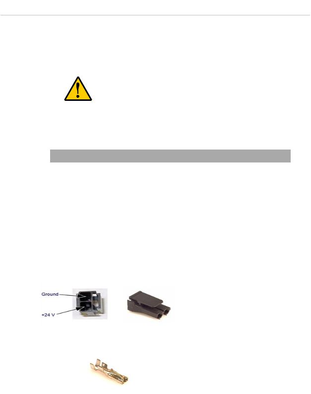
Details for 24 VDC Mating Connector
The 24 VDC mating connector and two pins are supplied with each system. They are shipped in the cable/accessories box.
Table 3-4. 24 VDC Mating Connector Specs |
||
|
|
|
Connector Details |
Connector receptacle, 2-position, type: |
|
|
Molex Saber, 18 A, 2-Pin |
|
|
|
|
|
Molex P/N 44441-2002 |
|
|
|
|
|
Digi-Key P/N WM18463-ND |
|
|
|
|
|
|
|
Pin Details |
Molex connector crimp terminal, |
|
|
female, 14-18 AWG |
|
|
|
|
|
Molex P/N 43375-0001 |
|
|
|
|
|
Digi-Key P/N WM18493-ND |
|
|
|
|
|
|
|
Recommended crimping tool, Molex Hand |
Molex P/N 63811-0400 |
|
Crimper |
|
|
Digi-Key P/N WM9907-ND |
||
|
||
|
|
|
Adept Cobra s350 User's Guide, Rev. D
Page 27 of 94

Chapter 3: System Cable Installation
NOTE: The 24 VDC cable is not supplied with the system, but is available in the optional Power Cable kit. See Table 3-1.
Procedure for Creating 24 VDC Cable
1.Locate the connector and pins from Table 3-4.
2.Use shielded two-conductor cable with 14-16 AWG wire to create the 24 VDC cable. Select the wire length to safely reach from the user-supplied 24 VDC power supply to the MB-40R/eMB-40R base.
You also must create a separate 24 VDC cable for the SmartController. That cable uses a different style of connector. See the Adept SmartController EX User's Guide or
Adept SmartController User's Guide.
3.Crimp the pins onto the wires using the crimping tool recommended in Table 3-4.
4.Insert the pins into the connector. Confirm that the +24 V and Ground wires are in the correct terminals in the plug.
5.Install a user-supplied ring lug (for an M3 screw) on the shield at the MB-40R/eMB-40R end of the cable.
6.Prepare the opposite end of the cable for connection to the user-supplied 24 VDC power supply, including a terminal to attach the cable shield to frame ground.
Installing the 24 VDC Cable
Do not turn on the 24 VDC power until instructed to do so in the next chapter.
1.Connect one end of the shielded 24 VDC cable to your user-supplied 24 VDC power supply. See Figure 3-2. The cable shield should be connected to frame ground on the power supply. Do not turn on the 24 VDC power until instructed to do so in System Operation on page 51.
2.Plug the mating connector end of the 24 VDC cable into the 24 VDC connector on the interface panel on the back of the MB-40R/eMB-40R. The cable shield should be connected to the ground point on the interface panel.
Adept Cobra s350 User's Guide, Rev. D
Page 28 of 94

Chapter 3: System Cable Installation
MB-40R/eMB-40R
Servo Controller
GND |
– |
+ |
User-Supplied Shielded
Attach shield from user- Power Cable supplied cable to ground
screw on MB-40R Interface Panel.
Adept SmartController |
Attach shield from user-supplied |
||
|
|
|
cable to side of controller using |
|
|
|
star washer and M3 x 6 screw. |
- +
User-Supplied Shielded
Power Cable
Figure 3-2. User-Supplied 24 VDC Cable
User-Supplied
Power Supply
24 VDC
+– 24V, 8A
Frame Ground
+– 24V, 5A
Attach shield from usersupplied cables to frame ground on power supply.
NOTE: Adept recommends that DC power be delivered over shielded cables, with the shield connected to frame ground at the power supply, and to the ground points shown in the diagram above for the MB-40R/eMB-40R and SmartController. The length of the wire from the cable shield to the ground points should be less than 50 mm.
3.9 Connecting 200-240 VAC Power to MB-40R/eMB-40R
WARNING: Ensure compliance with all local and national safety and electrical codes for the installation and operation of the robot system.
WARNING: Appropriately-sized Branch Circuit Protection and Lockout / Tagout Capability must be provided in accordance with the National Electrical Code and any local codes.
Adept Cobra s350 User's Guide, Rev. D
Page 29 of 94
Loading...