


 Loading...
Adept Quattro
s650 Robot
User’s Guide

Adept Quattro
s650 Robot
User’s Guide
P/N: 08411-000, Rev B
February, 2008
3011 Triad Drive • Livermore, CA 94551 • USA • Phone 925.245.3400 • Fax 925.960.0452 Otto-Hahn-Strasse 23 • 44227 Dortmund • Germany • Phone +49.231.75.89.40 • Fax +49.231.75.89.450
151 Lorong Chuan #04-07 • New Tech Park, Lobby G • Singapore 556741 • Phone +65.6281.5731 • Fax +65.6280.5714
The information contained herein is the property of Adept Technology, Inc., and shall not be reproduced in whole or in part without prior written approval of Adept Technology, Inc. The information herein is subject to change without notice and should not be construed as a commitment by Adept Technology, Inc. This manual is periodically reviewed and revised.
Adept Technology, Inc., assumes no responsibility for any errors or omissions in this document. Critical evaluation of this manual by the user is welcomed. Your comments assist us in preparation of future documentation. Please email your comments to: techpubs@adept.com.
Copyright ©2007, 2008 by Adept Technology, Inc. All rights reserved.
Adept, the Adept logo, the Adept Technology logo, AdeptVision, AIM, Blox, Bloxview, FireBlox, Fireview, HexSight, Meta Controls, MetaControls, Metawire, Soft Machines, and Visual Machines are registered trademarks of Adept Technology, Inc. Brain on Board is a registered trademark of Adept Technology, Inc. in Germany.
ACE, ActiveV, Adept 1060 / 1060+, Adept 1850 / 1850 XP, Adept 540 Adept 560, Adept AnyFeeder, Adept Award, Adept C40, Adept C60, Adept CC, Adept Cobra 350, Adept Cobra 350 CR/ESD, Adept Cobra 550, Adept 550 CleanRoom, Adept Cobra 600, Adept Cobra 800, Adept Cobra i600, Adept Cobra i800, Adept Cobra PLC server, Adept Cobra PLC800, Adept Cobra s600, Adept Cobra s800, Adept Cobra s800 Inverted, Adept Cobra Smart600, Adept Cobra Smart800, Adept DeskTop,
Adept FFE, Adept FlexFeeder 250, Adept IC, Adept iSight, Adept Impulse Feeder, Adept LineVision, Adept MB-10 ServoKit, Adept MC, Adept MotionBlox-10, Adept MotionBlox-40L, Adept MotionBlox-40R, Adept MV Adept MV-10, Adept MV-19, Adept MV4, Adept MV-5, Adept MV-8, Adept OC, Adept Python, Adept Quattro s650, Adept sDIO, Adept SmartAmp, Adept SmartAxis, Adept SmartController CS, Adept SmartController CX, Adept SmartModule, Adept SmartMotion, Adept SmartServo, Adept sMI6, Adept sSight, Adept Viper s650, Adept Viper s850, Adept Viper s1300, Adept Viper s1700, Adept Viper s2000, AdeptCartesian, AdeptCast, AdeptForce, AdeptFTP, AdeptGEM, AdeptModules, AdeptMotion, AdeptMotion Servo, AdeptMotion VME, AdeptNet, AdeptNFS,
AdeptOne, AdeptOne-MV, AdeptOne-XL, AdeptRAPID, AdeptSight, AdeptSix, AdeptSix 300, AdeptSix 300 CL, AdeptSix 300 CR, AdeptSix 600, AdeptTCP/IP, AdeptThree, AdeptThree-MV, AdeptThree-XL, AdeptTwo, AdeptVision, AVI AdeptVision, AGS AdeptVision GV, AdeptVision I, AdeptVision II,
AdeptVision VME, AdeptVision VXL, AdeptVision XGS, AdeptVision XGS II, AdeptWindows, AdeptWindows Controller, AdeptWindows DDE, AdeptWindows Offline Editor, AdeptWindows PC, AIM Command Server, AIM Dispense, AIM PCB, AIM VisionWare, A-Series, FlexFeedWare, HyperDrive, IO Blox, IO Blox, 88, MicroV+, MotionBlox, MotionWare, ObjectFinder, ObjectFinder 2000, PackOne, PalletWare, sAVI, S-Series, UltraOne, V, V+ and VisionTeach are trademarks of Adept Technology, Inc.
Any trademarks from other companies used in this publication are the property of those respective companies.
Printed in the United States of America

Table of Contents
1 Introduction . . . . . . . . . . . . . . . . . . . . . . . . . . . . . . . . . . . . . . . . . . . . . . . |
13 |
1.1 Product Description. . . . . . . . . . . . . . . . . . . . . . . . . . . . . . . . . . . . . . . . . . . . . . . . 13
Adept Quattro s650 Robot . . . . . . . . . . . . . . . . . . . . . . . . . . . . . . . . . . . . . . . 13
Quattro Robot Base. . . . . . . . . . . . . . . . . . . . . . . . . . . . . . . . . . . . . . . . . . . . . 14
Adept AIB . . . . . . . . . . . . . . . . . . . . . . . . . . . . . . . . . . . . . . . . . . . . . . . . . . . . . 14
Inner Arms . . . . . . . . . . . . . . . . . . . . . . . . . . . . . . . . . . . . . . . . . . . . . . . . . . . . . 15
Ball Joints, Outer Arms . . . . . . . . . . . . . . . . . . . . . . . . . . . . . . . . . . . . . . . . . . . 16
Platform. . . . . . . . . . . . . . . . . . . . . . . . . . . . . . . . . . . . . . . . . . . . . . . . . . . . . . . 16
Adept SmartController CX . . . . . . . . . . . . . . . . . . . . . . . . . . . . . . . . . . . . . . . 20
1.2 Installation Overview . . . . . . . . . . . . . . . . . . . . . . . . . . . . . . . . . . . . . . . . . . . . . . 20
1.3 Manufacturer’s Declaration . . . . . . . . . . . . . . . . . . . . . . . . . . . . . . . . . . . . . . . . . 21
1.4 How Can I Get Help? . . . . . . . . . . . . . . . . . . . . . . . . . . . . . . . . . . . . . . . . . . . . . . 21
Related Manuals . . . . . . . . . . . . . . . . . . . . . . . . . . . . . . . . . . . . . . . . . . . . . . . 22
Adept Document Library . . . . . . . . . . . . . . . . . . . . . . . . . . . . . . . . . . . . . . . . 22
2 Safety . . . . . . . . . . . . . . . . . . . . . . . . . . . . . . . . . . . . . . . . . . . . . . . . . . . . |
23 |
2.1 Warnings, Cautions, and Notes in Manual . . . . . . . . . . . . . . . . . . . . . . . . . . . . . 23 2.2 Warning Labels on the Robot . . . . . . . . . . . . . . . . . . . . . . . . . . . . . . . . . . . . . . . . 24 2.3 Precautions and Required Safeguards . . . . . . . . . . . . . . . . . . . . . . . . . . . . . . . 24
Safety Barriers . . . . . . . . . . . . . . . . . . . . . . . . . . . . . . . . . . . . . . . . . . . . . . . . . . 24 Impact and Trapping Points . . . . . . . . . . . . . . . . . . . . . . . . . . . . . . . . . . . . . 25 Instructions for Emergency Movement without Drive Power . . . . . . . . . . . 25 Emergency Recovery Procedures . . . . . . . . . . . . . . . . . . . . . . . . . . . . . . . . . 25 Additional Safety Information . . . . . . . . . . . . . . . . . . . . . . . . . . . . . . . . . . . . 25
2.4 Risk Assessment. . . . . . . . . . . . . . . . . . . . . . . . . . . . . . . . . . . . . . . . . . . . . . . . . . . 27
Exposure . . . . . . . . . . . . . . . . . . . . . . . . . . . . . . . . . . . . . . . . . . . . . . . . . . . . . . 27
Severity of Injury . . . . . . . . . . . . . . . . . . . . . . . . . . . . . . . . . . . . . . . . . . . . . . . . 27
Slow Speed Control Function and Testing . . . . . . . . . . . . . . . . . . . . . . . . . . 28
2.5 Intended Use of the Robots . . . . . . . . . . . . . . . . . . . . . . . . . . . . . . . . . . . . . . . . . 29 2.6 Robot Modifications . . . . . . . . . . . . . . . . . . . . . . . . . . . . . . . . . . . . . . . . . . . . . . . 30
Acceptable Modifications . . . . . . . . . . . . . . . . . . . . . . . . . . . . . . . . . . . . . . . 30
Unacceptable Modifications . . . . . . . . . . . . . . . . . . . . . . . . . . . . . . . . . . . . 30
2.7 Transport. . . . . . . . . . . . . . . . . . . . . . . . . . . . . . . . . . . . . . . . . . . . . . . . . . . . . . . . . 31 2.8 Safety Requirements for Additional Equipment . . . . . . . . . . . . . . . . . . . . . . . . . 31 2.9 Sound Emissions . . . . . . . . . . . . . . . . . . . . . . . . . . . . . . . . . . . . . . . . . . . . . . . . . . 31 2.10 Thermal Hazard . . . . . . . . . . . . . . . . . . . . . . . . . . . . . . . . . . . . . . . . . . . . . . . . . . 32
Adept Quattro s650 Robot User’s Guide, Rev B |
5 |

Table of Contents
2.11 Working Areas . . . . . . . . . . . . . . . . . . . . . . . . . . . . . . . . . . . . . . . . . . . . . . . . . . . 32
2.12 Qualification of Personnel . . . . . . . . . . . . . . . . . . . . . . . . . . . . . . . . . . . . . . . . . . 32
2.13 Safety Equipment for Operators . . . . . . . . . . . . . . . . . . . . . . . . . . . . . . . . . . . . 33 2.14 Protection Against Unauthorized Operation . . . . . . . . . . . . . . . . . . . . . . . . . . . 33
2.15 Safety Aspects While Performing Maintenance . . . . . . . . . . . . . . . . . . . . . . . . 33
2.16 Risks Due to Incorrect Installation or Operation . . . . . . . . . . . . . . . . . . . . . . . . 34 2.17 What to Do in an Emergency . . . . . . . . . . . . . . . . . . . . . . . . . . . . . . . . . . . . . . . 34
3 Robot Installation . . . . . . . . . . . . . . . . . . . . . . . . . . . . . . . . . . . . . . . . . . . 35
3.1 Transport and Storage . . . . . . . . . . . . . . . . . . . . . . . . . . . . . . . . . . . . . . . . . . . . . . 35 3.2 Unpacking and Inspecting the Adept Equipment . . . . . . . . . . . . . . . . . . . . . . . 35
Before Unpacking . . . . . . . . . . . . . . . . . . . . . . . . . . . . . . . . . . . . . . . . . . . . . . . 35
Unpacking . . . . . . . . . . . . . . . . . . . . . . . . . . . . . . . . . . . . . . . . . . . . . . . . . . . . . 35
Upon Unpacking . . . . . . . . . . . . . . . . . . . . . . . . . . . . . . . . . . . . . . . . . . . . . . . . 37
3.3 Repacking for Relocation . . . . . . . . . . . . . . . . . . . . . . . . . . . . . . . . . . . . . . . . . . . 37 3.4 Environmental and Facility Requirements . . . . . . . . . . . . . . . . . . . . . . . . . . . . . 38 3.5 Mounting Frame . . . . . . . . . . . . . . . . . . . . . . . . . . . . . . . . . . . . . . . . . . . . . . . . . . . 38
Overview . . . . . . . . . . . . . . . . . . . . . . . . . . . . . . . . . . . . . . . . . . . . . . . . . . . . . . 38
Frame Orientation. . . . . . . . . . . . . . . . . . . . . . . . . . . . . . . . . . . . . . . . . . . . . . . 40
Frame Construction . . . . . . . . . . . . . . . . . . . . . . . . . . . . . . . . . . . . . . . . . . . . . 40
Robot-to-Frame Considerations . . . . . . . . . . . . . . . . . . . . . . . . . . . . . . . . . . . 40
Gussets . . . . . . . . . . . . . . . . . . . . . . . . . . . . . . . . . . . . . . . . . . . . . . . . . . . . . . . . 41
3.6 Mounting the Robot Base . . . . . . . . . . . . . . . . . . . . . . . . . . . . . . . . . . . . . . . . . . . 41
Robot Orientation . . . . . . . . . . . . . . . . . . . . . . . . . . . . . . . . . . . . . . . . . . . . . . . 41 Mounting Surfaces . . . . . . . . . . . . . . . . . . . . . . . . . . . . . . . . . . . . . . . . . . . . . . 41 Mounting Options . . . . . . . . . . . . . . . . . . . . . . . . . . . . . . . . . . . . . . . . . . . . . . . 42 Mounting Procedure from Above the Frame . . . . . . . . . . . . . . . . . . . . . . . . 42 Mounting Procedure from Below the Frame . . . . . . . . . . . . . . . . . . . . . . . . . 44 Install Mounting Hardware. . . . . . . . . . . . . . . . . . . . . . . . . . . . . . . . . . . . . . . . 44
3.7 Attaching the Outer Arms and Platform . . . . . . . . . . . . . . . . . . . . . . . . . . . . . . . 46
Clocking the Platform to the Base . . . . . . . . . . . . . . . . . . . . . . . . . . . . . . . . . 46 Attaching the Outer Arms . . . . . . . . . . . . . . . . . . . . . . . . . . . . . . . . . . . . . . . . 48
4 System Installation . . . . . . . . . . . . . . . . . . . . . . . . . . . . . . . . . . . . . . . . . . 51
4.1 System Cable Diagram . . . . . . . . . . . . . . . . . . . . . . . . . . . . . . . . . . . . . . . . . . . . 51 4.2 Cable Parts List . . . . . . . . . . . . . . . . . . . . . . . . . . . . . . . . . . . . . . . . . . . . . . . . . . . . 52 4.3 Installing the SmartController . . . . . . . . . . . . . . . . . . . . . . . . . . . . . . . . . . . . . . . . 52 4.4 Description of Connectors on Robot Interface Panel . . . . . . . . . . . . . . . . . . . . 53 4.5 Cable Connections from Robot to SmartController . . . . . . . . . . . . . . . . . . . . . . 54
6 |
Adept Quattro s650 Robot User’s Guide, Rev B |

|
|
Table of Contents |
4.6 |
Connecting 24 VDC Power to Robot . . . . . . . . . . . . . . . . . . . . . . |
. . . . . . . . . . . 54 |
|
Specifications for 24 VDC Robot and Controller Power . . . . |
. . . . . . . . . . . 54 |
|
Details for 24 VDC Mating Connector . . . . . . . . . . . . . . . . . . |
. . . . . . . . . . . 55 |
|
Procedure for Creating 24 VDC Cable . . . . . . . . . . . . . . . . . |
. . . . . . . . . . . 56 |
|
Installing 24 VDC Robot Cable. . . . . . . . . . . . . . . . . . . . . . . . . |
. . . . . . . . . . . 56 |
4.7 |
Connecting 200-240 VAC Power to Robot . . . . . . . . . . . . . . . . . |
. . . . . . . . . . . 57 |
|
Specifications for AC Power . . . . . . . . . . . . . . . . . . . . . . . . . . |
. . . . . . . . . . . 58 |
|
Details for AC Mating Connector . . . . . . . . . . . . . . . . . . . . . . |
. . . . . . . . . . . 60 |
|
Procedure for Creating 200-240 VAC Cable . . . . . . . . . . . . . |
. . . . . . . . . . . 60 |
|
Installing AC Power Cable to Robot . . . . . . . . . . . . . . . . . . . . |
. . . . . . . . . . . 61 |
4.8 |
Grounding the Adept Quattro s650 Robot System. . . . . . . . . . . . |
. . . . . . . . . . . 61 |
|
Robot-Mounted Equipment Grounding . . . . . . . . . . . . . . . . . |
. . . . . . . . . . . 61 |
4.9 |
Installing User-Supplied Safety Equipment . . . . . . . . . . . . . . . . . |
. . . . . . . . . . . 62 |
5 System Operation . . . . . . . . . . . . . . . . . . . . . . . . . . . . . . . . . |
. . . . . . . . . 63 |
|
5.1 |
Robot Status LED Description . . . . . . . . . . . . . . . . . . . . . . . . . . . . . |
. . . . . . . . . . . 63 |
5.2 |
Status Panel Fault Codes . . . . . . . . . . . . . . . . . . . . . . . . . . . . . . . . |
. . . . . . . . . . . 64 |
5.3 |
Using the Brake Release Button . . . . . . . . . . . . . . . . . . . . . . . . . . . |
. . . . . . . . . . . 65 |
|
Brakes . . . . . . . . . . . . . . . . . . . . . . . . . . . . . . . . . . . . . . . . . . . . . |
. . . . . . . . . . . 65 |
|
Brake Release Button. . . . . . . . . . . . . . . . . . . . . . . . . . . . . . . . . |
. . . . . . . . . . . 65 |
5.4 |
Connecting Digital I/O to the System . . . . . . . . . . . . . . . . . . . . . . |
. . . . . . . . . . . 65 |
5.5 |
Using Digital I/O on Robot XIO Connector . . . . . . . . . . . . . . . . . |
. . . . . . . . . . . 67 |
|
XIO Input Signals. . . . . . . . . . . . . . . . . . . . . . . . . . . . . . . . . . . . . |
. . . . . . . . . . . 69 |
|
XIO Breakout Cable . . . . . . . . . . . . . . . . . . . . . . . . . . . . . . . . . |
. . . . . . . . . . . 72 |
5.6 |
Commissioning the System . . . . . . . . . . . . . . . . . . . . . . . . . . . . . . |
. . . . . . . . . . . 73 |
|
Verifying Installation . . . . . . . . . . . . . . . . . . . . . . . . . . . . . . . . . |
. . . . . . . . . . . 74 |
|
System Start-up Procedure . . . . . . . . . . . . . . . . . . . . . . . . . . . |
. . . . . . . . . . . 75 |
|
Verifying E-Stop Functions . . . . . . . . . . . . . . . . . . . . . . . . . . . . . |
. . . . . . . . . . . 76 |
|
Verifying Robot Motions. . . . . . . . . . . . . . . . . . . . . . . . . . . . . . . |
. . . . . . . . . . . 76 |
5.7 |
Quattro Motions. . . . . . . . . . . . . . . . . . . . . . . . . . . . . . . . . . . . . . . . |
. . . . . . . . . . . 76 |
|
Straight-line Motion . . . . . . . . . . . . . . . . . . . . . . . . . . . . . . . . . . |
. . . . . . . . . . . 76 |
|
Containment Obstacles . . . . . . . . . . . . . . . . . . . . . . . . . . . . . . |
. . . . . . . . . . . 77 |
|
Tool Flange Rotation Extremes . . . . . . . . . . . . . . . . . . . . . . . . . |
. . . . . . . . . . . 77 |
5.8 |
Learning to Program the Adept Quattro Robot . . . . . . . . . . . . . . |
. . . . . . . . . . . 82 |
6 Optional Equipment Installation . . . . . . . . . . . . . . . . . . . . . . |
. . . . . . . . . 83 |
|
6.1 |
End-Effectors . . . . . . . . . . . . . . . . . . . . . . . . . . . . . . . . . . . . . . . . . . |
. . . . . . . . . . . 83 |
|
Attaching, Aligning . . . . . . . . . . . . . . . . . . . . . . . . . . . . . . . . . . |
. . . . . . . . . . . 83 |
|
Grounding. . . . . . . . . . . . . . . . . . . . . . . . . . . . . . . . . . . . . . . . . . |
. . . . . . . . . . . 83 |
|
Accessing Vacuum . . . . . . . . . . . . . . . . . . . . . . . . . . . . . . . . . . |
. . . . . . . . . . . 83 |
6.2 |
Routing End-effector Lines . . . . . . . . . . . . . . . . . . . . . . . . . . . . . . . |
. . . . . . . . . . . 84 |
Adept Quattro s650 Robot User’s Guide, Rev B |
7 |

Table of Contents
7 Technical Specifications . . . . . . . . . . . . . . . . . . . . . . . . . . . . . . . . . . . . . 85
7.1 Dimension Drawings . . . . . . . . . . . . . . . . . . . . . . . . . . . . . . . . . . . . . . . . . . . . . . . 85
7.2 Adept Quattro s650 Robot Internal Connections . . . . . . . . . . . . . . . . . . . . . . . . 89
7.3 XSLV Connector . . . . . . . . . . . . . . . . . . . . . . . . . . . . . . . . . . . . . . . . . . . . . . . . . . . 90
7.4 Robot Specifications . . . . . . . . . . . . . . . . . . . . . . . . . . . . . . . . . . . . . . . . . . . . . . . 91
7.5 Platform Specifications . . . . . . . . . . . . . . . . . . . . . . . . . . . . . . . . . . . . . . . . . . . . . 92
Rotation and Payload Inertia - Range . . . . . . . . . . . . . . . . . . . . . . . . . . . . . . 92
Rotation and Payload Inertia - Performance . . . . . . . . . . . . . . . . . . . . . . . . 92
7.6 Robot Mounting Frame . . . . . . . . . . . . . . . . . . . . . . . . . . . . . . . . . . . . . . . . . . . . . 93
8 Maintenance . . . . . . . . . . . . . . . . . . . . . . . . . . . . . . . . . . . . . . . . . . . . . . 99
8.1 Periodic Maintenance Schedule . . . . . . . . . . . . . . . . . . . . . . . . . . . . . . . . . . . . . 99
8.2 Checking Safety Systems . . . . . . . . . . . . . . . . . . . . . . . . . . . . . . . . . . . . . . . . . . 100
8.3 Checking Robot Mounting Bolts . . . . . . . . . . . . . . . . . . . . . . . . . . . . . . . . . . . . . 100
8.4 Checking Robot Gear Drives . . . . . . . . . . . . . . . . . . . . . . . . . . . . . . . . . . . . . . . 100
8.5 Checking Fan Operation . . . . . . . . . . . . . . . . . . . . . . . . . . . . . . . . . . . . . . . . . . 101
8.6 Replacing the AIB Chassis . . . . . . . . . . . . . . . . . . . . . . . . . . . . . . . . . . . . . . . . . 101
Removing the AIB Chassis . . . . . . . . . . . . . . . . . . . . . . . . . . . . . . . . . . . . . . . 101
Installing a New AIB Chassis . . . . . . . . . . . . . . . . . . . . . . . . . . . . . . . . . . . . . . 104
8.7 Replacing the Encoder Battery. . . . . . . . . . . . . . . . . . . . . . . . . . . . . . . . . . . . . . 105
Battery Replacement Time Periods . . . . . . . . . . . . . . . . . . . . . . . . . . . . . . . 105
Battery Replacement Procedure . . . . . . . . . . . . . . . . . . . . . . . . . . . . . . . . . 105
8.8 Replacing a Platform . . . . . . . . . . . . . . . . . . . . . . . . . . . . . . . . . . . . . . . . . . . . . . 106
Replacement . . . . . . . . . . . . . . . . . . . . . . . . . . . . . . . . . . . . . . . . . . . . . . . . . 106
Configuration . . . . . . . . . . . . . . . . . . . . . . . . . . . . . . . . . . . . . . . . . . . . . . . . . 107
9 Robot Cleaning/ Environmental Concerns . . . . . . . . . . . . . . . . . . . . . |
111 |
9.1 Ambient Environment . . . . . . . . . . . . . . . . . . . . . . . . . . . . . . . . . . . . . . . . . . . . . 111
Humidity . . . . . . . . . . . . . . . . . . . . . . . . . . . . . . . . . . . . . . . . . . . . . . . . . . . . . . 111
Temperature . . . . . . . . . . . . . . . . . . . . . . . . . . . . . . . . . . . . . . . . . . . . . . . . . . 112
9.2 Cleaning . . . . . . . . . . . . . . . . . . . . . . . . . . . . . . . . . . . . . . . . . . . . . . . . . . . . . . . . 112
Caustic Compatibility. . . . . . . . . . . . . . . . . . . . . . . . . . . . . . . . . . . . . . . . . . . 112
Water Shedding . . . . . . . . . . . . . . . . . . . . . . . . . . . . . . . . . . . . . . . . . . . . . . . 112
Wipe-Down . . . . . . . . . . . . . . . . . . . . . . . . . . . . . . . . . . . . . . . . . . . . . . . . . . . 112
9.3 Cleanroom Classification . . . . . . . . . . . . . . . . . . . . . . . . . . . . . . . . . . . . . . . . . . 112
8 |
Adept Quattro s650 Robot User’s Guide, Rev B |

|
Table of Contents |
9.4 Design Factors . . . . . . . . . . . . . . . . . . . . . . . . . . . . . . . . . . . . . . . . . |
. . . . . . . . . . 113 |
Robot Base and Components . . . . . . . . . . . . . . . . . . . . . . . . . |
. . . . . . . . . . 113 |
Inner Arms . . . . . . . . . . . . . . . . . . . . . . . . . . . . . . . . . . . . . . . . . . |
. . . . . . . . . . 113 |
Ball Joints. . . . . . . . . . . . . . . . . . . . . . . . . . . . . . . . . . . . . . . . . . . |
. . . . . . . . . . 113 |
Outer Arms . . . . . . . . . . . . . . . . . . . . . . . . . . . . . . . . . . . . . . . . . |
. . . . . . . . . . 114 |
Springs . . . . . . . . . . . . . . . . . . . . . . . . . . . . . . . . . . . . . . . . . . . . . |
. . . . . . . . . . 114 |
Platforms . . . . . . . . . . . . . . . . . . . . . . . . . . . . . . . . . . . . . . . . . . . |
. . . . . . . . . . 114 |
9.5 Installing Cable Seal Kit . . . . . . . . . . . . . . . . . . . . . . . . . . . . . . . . . |
. . . . . . . . . . 115 |
Overview. . . . . . . . . . . . . . . . . . . . . . . . . . . . . . . . . . . . . . . . . . . |
. . . . . . . . . . 115 |
Installation Procedure . . . . . . . . . . . . . . . . . . . . . . . . . . . . . . . . |
. . . . . . . . . . 115 |
Adept Quattro s650 Robot User’s Guide, Rev B |
9 |
|
List of Figures |
|
Figure 1-1. |
Adept Quattro s650 Robot . . . . . . . . . . . . . . . . . . . . . . . . . . . . . . . . . . . . . . . . |
13 |
Figure 1-2. |
Major Robot Components, Isometric View . . . . . . . . . . . . . . . . . . . . . . . . . . |
14 |
Figure 1-3. |
Adept AIB . . . . . . . . . . . . . . . . . . . . . . . . . . . . . . . . . . . . . . . . . . . . . . . . . . . . . . |
15 |
Figure 1-4. |
Robot Inner Arm . . . . . . . . . . . . . . . . . . . . . . . . . . . . . . . . . . . . . . . . . . . . . . . . |
15 |
Figure 1-5. |
Ball Joints between Inner and Outer Arms . . . . . . . . . . . . . . . . . . . . . . . . . . . |
16 |
Figure 1-6. |
4:1 Platform, Top View . . . . . . . . . . . . . . . . . . . . . . . . . . . . . . . . . . . . . . . . . . . |
18 |
Figure 1-7. |
4:1 Platform, Bottom View . . . . . . . . . . . . . . . . . . . . . . . . . . . . . . . . . . . . . . . . |
18 |
Figure 1-8. |
1:1 Platform, Top View . . . . . . . . . . . . . . . . . . . . . . . . . . . . . . . . . . . . . . . . . . . |
19 |
Figure 1-9. |
1:1 Platform, Bottom View . . . . . . . . . . . . . . . . . . . . . . . . . . . . . . . . . . . . . . . . |
19 |
Figure 1-10. |
Adept SmartController CX . . . . . . . . . . . . . . . . . . . . . . . . . . . . . . . . . . . . . . . . |
20 |
Figure 2-1. |
Electrical and Thermal Warning Labels on AIB Chassis . . . . . . . . . . . . . . . . . |
24 |
Figure 3-1. |
Quattro Shipping Crates . . . . . . . . . . . . . . . . . . . . . . . . . . . . . . . . . . . . . . . . . . |
36 |
Figure 3-2. |
Crates with Front Panel/SIdes Removed . . . . . . . . . . . . . . . . . . . . . . . . . . . . |
37 |
Figure 3-3. |
Sample Quattro Mounting Frame . . . . . . . . . . . . . . . . . . . . . . . . . . . . . . . . . . |
39 |
Figure 3-4. |
Location of Slings for Lifting Robot Base . . . . . . . . . . . . . . . . . . . . . . . . . . . . . |
43 |
Figure 3-5. |
Major Robot Components, Top View . . . . . . . . . . . . . . . . . . . . . . . . . . . . . . . |
46 |
Figure 3-6. |
End Cap Labeling, Joint #1 . . . . . . . . . . . . . . . . . . . . . . . . . . . . . . . . . . . . . . . |
47 |
Figure 3-7. |
Platform Orientation Labeling . . . . . . . . . . . . . . . . . . . . . . . . . . . . . . . . . . . . . |
47 |
Figure 3-8. |
Inner Arm Ball Studs . . . . . . . . . . . . . . . . . . . . . . . . . . . . . . . . . . . . . . . . . . . . . . |
48 |
Figure 3-9. |
Ball Joint Assembly . . . . . . . . . . . . . . . . . . . . . . . . . . . . . . . . . . . . . . . . . . . . . . |
49 |
Figure 3-10. |
Installing Ball Joints . . . . . . . . . . . . . . . . . . . . . . . . . . . . . . . . . . . . . . . . . . . . . . |
49 |
Figure 4-1. |
System Cable Diagram . . . . . . . . . . . . . . . . . . . . . . . . . . . . . . . . . . . . . . . . . . |
51 |
Figure 4-2. |
Robot Interface Panel . . . . . . . . . . . . . . . . . . . . . . . . . . . . . . . . . . . . . . . . . . . |
53 |
Figure 4-3. |
User-Supplied 24 VDC Cable . . . . . . . . . . . . . . . . . . . . . . . . . . . . . . . . . . . . . . |
57 |
Figure 4-4. |
Typical AC Power Installation with Single-Phase Supply . . . . . . . . . . . . . . . . |
59 |
Figure 4-5. |
Single-Phase AC Power Installation from a Three-Phase AC Supply . . . . . . |
59 |
Figure 4-6. |
AC Power Mating Connector . . . . . . . . . . . . . . . . . . . . . . . . . . . . . . . . . . . . . |
60 |
Figure 5-1. |
Robot Status LED Indicator Location . . . . . . . . . . . . . . . . . . . . . . . . . . . . . . . |
63 |
Figure 5-2. |
Connecting Digital I/O to the System . . . . . . . . . . . . . . . . . . . . . . . . . . . . . . . |
66 |
Figure 5-3. |
Typical User Wiring for XIO Input Signals . . . . . . . . . . . . . . . . . . . . . . . . . . . . . |
70 |
Figure 5-4. |
Typical User Wiring for XIO Output Signals . . . . . . . . . . . . . . . . . . . . . . . . . . . |
72 |
Figure 5-5. |
Optional XIO Breakout Cable . . . . . . . . . . . . . . . . . . . . . . . . . . . . . . . . . . . . . |
72 |
Figure 5-6. |
Typical Startup Screen . . . . . . . . . . . . . . . . . . . . . . . . . . . . . . . . . . . . . . . . . . . |
75 |
Figure 5-7. |
Ambiguity Zone . . . . . . . . . . . . . . . . . . . . . . . . . . . . . . . . . . . . . . . . . . . . . . . . . |
78 |
Figure 5-8. |
Illegal Move . . . . . . . . . . . . . . . . . . . . . . . . . . . . . . . . . . . . . . . . . . . . . . . . . . . . |
78 |
Figure 5-9. |
Legal Move . . . . . . . . . . . . . . . . . . . . . . . . . . . . . . . . . . . . . . . . . . . . . . . . . . . . |
79 |
Figure 7-1. |
Top Dimensions, Work Envelope, and Mounting Hole Pattern . . . . . . . . . . |
85 |
Figure 7-2. |
Tool Flange Dimensions . . . . . . . . . . . . . . . . . . . . . . . . . . . . . . . . . . . . . . . . . . |
86 |
Figure 7-3. |
Work Envelope, Side View . . . . . . . . . . . . . . . . . . . . . . . . . . . . . . . . . . . . . . . . |
87 |
Adept Quattro s650 Robot User’s Guide, Rev B |
11 |

List of Figures |
|
|
Figure 7-4. |
Arm Travel Volume . . . . . . . . . . . . . . . . . . . . . . . . . . . . . . . . . . . . . . . . . . . . . . |
. 88 |
Figure 7-5. |
Robot Internal Connections Diagram . . . . . . . . . . . . . . . . . . . . . . . . . . . . . . |
. 89 |
Figure 7-6. |
Mounting Frame, Orthogonal View . . . . . . . . . . . . . . . . . . . . . . . . . . . . . . . . . |
94 |
Figure 7-7. |
Mounting Frame, Side View 1 . . . . . . . . . . . . . . . . . . . . . . . . . . . . . . . . . . . . . . |
95 |
Figure 7-8. |
Mounting Frame, Side View 2 . . . . . . . . . . . . . . . . . . . . . . . . . . . . . . . . . . . . . . |
95 |
Figure 7-9. |
Mounting Frame, Detail 1 . . . . . . . . . . . . . . . . . . . . . . . . . . . . . . . . . . . . . . . . . |
96 |
Figure 7-10. |
Mounting Frame, Detail 2 . . . . . . . . . . . . . . . . . . . . . . . . . . . . . . . . . . . . . . . . . |
96 |
Figure 7-11. |
Mounting Frame, Top View . . . . . . . . . . . . . . . . . . . . . . . . . . . . . . . . . . . . . . . . |
97 |
Figure 8-1. |
Securing Screw on AIB Chassis . . . . . . . . . . . . . . . . . . . . . . . . . . . . . . . . . . . . |
102 |
Figure 8-2. |
Opening the AIB Chassis . . . . . . . . . . . . . . . . . . . . . . . . . . . . . . . . . . . . . . . . . |
102 |
Figure 8-3. |
Connectors on AIB Chassis . . . . . . . . . . . . . . . . . . . . . . . . . . . . . . . . . . . . . . . |
103 |
Figure 8-4. |
Ground Screw on AIB Chassis . . . . . . . . . . . . . . . . . . . . . . . . . . . . . . . . . . . . . |
103 |
Figure 8-5. |
Battery in Quattro Base . . . . . . . . . . . . . . . . . . . . . . . . . . . . . . . . . . . . . . . . . . |
106 |
Figure 8-6. |
SPEC Utility Load Function . . . . . . . . . . . . . . . . . . . . . . . . . . . . . . . . . . . . . . . . |
108 |
Figure 8-7. |
SPEC Save Specification Menu . . . . . . . . . . . . . . . . . . . . . . . . . . . . . . . . . . . |
109 |
Figure 9-1. |
AIB Cable Seal Housing (left), Installed (right) . . . . . . . . . . . . . . . . . . . . . . . |
116 |
Figure 9-2. |
Cable Entry Top Cover Assembly . . . . . . . . . . . . . . . . . . . . . . . . . . . . . . . . . . |
116 |
Figure 9-3. |
Bottom of Cable Entry Top Cover, CF Frame . . . . . . . . . . . . . . . . . . . . . . . . |
116 |
Figure 9-4. |
Adapting the module to the cable size (left) and |
|
|
checking the gap in the module (right). . . . . . . . . . . . . . . . . . . . . . . . . . . . . |
117 |
Figure 9-5. |
Greasing a Roxtec Module . . . . . . . . . . . . . . . . . . . . . . . . . . . . . . . . . . . . . . . |
117 |
Figure 9-6. |
Installing Roxtec Modules into the Frame . . . . . . . . . . . . . . . . . . . . . . . . . . . |
117 |
Figure 9-7. |
Tightening the Compression Unit . . . . . . . . . . . . . . . . . . . . . . . . . . . . . . . . . . |
118 |
Figure 9-8. |
Cable Entry Assembly with Cables . . . . . . . . . . . . . . . . . . . . . . . . . . . . . . . . . |
118 |
Figure 9-9. |
Ground Lug Attachment on the AIB . . . . . . . . . . . . . . . . . . . . . . . . . . . . . . . |
119 |
Figure 9-10. |
Installing Cable Entry Top Cover Assembly . . . . . . . . . . . . . . . . . . . . . . . . . . |
119 |
12 |
Adept Quattro s650 Robot User’s Guide, Rev B |

Introduction 1
1.1Product Description
Adept Quattro s650 Robot
The Adept Quattro s650 robot is a four-axis parallel robot. See Figure 1-1. The four identical axis motors control movement of the robot tool in X, Y, and Z directions, as well as Theta rotation.
The Adept Quattro s650 robot requires an Adept SmartController CX for operation. The robot is user-programmed and controlled using the SmartController.
NOTE: The Adept SmartController CX must be installed inside a NEMA-1 rated enclosure.
The robot servo code runs on an Adept SmartServo distributed motion control platform embedded in the robot base.
Mechanical specifications for the Adept Quattro s650 robot are provided in Chapter 7.
Figure 1-1. Adept Quattro s650 Robot
Adept Quattro s650 Robot User’s Guide, Rev B |
13 |

Chapter 1 - Introduction
Mounting Pads |
Motor Cover |
|
|
AIB |
Inner Arm |
|
Base
Outer
 Arms
Arms 
Ball
Joints
Platform
Tool
Flange
Figure 1-2. Major Robot Components, Isometric View
Quattro Robot Base
The Adept Quattro s650 robot base is an aluminum casting that houses the four drive motors, and supports the AIB (Amplifiers-In-Base). It provides four mounting pads for attaching the base to a rigid support frame. The status LED and status panel are mounted on the side of the robot base.
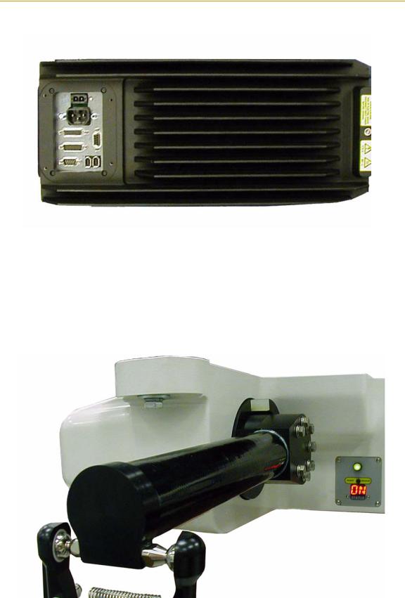
Adept AIB
The power amplifiers for the Adept Quattro s650 robot are embedded in the base of the robot. This amplifier section is known as the AIB distributed motion control platform, and provides closed-loop servo control of the robot amplifiers, as well as robot I/O.
Adept AIB features:
•On-board digital I/O: 12 inputs, 8 outputs
•Low EMI for use with noise-sensitive equipment
•No external fan
•8 kHz servo rate
•Sine wave commutation
•Digital feed-forward design
•Temperature sensors on all amplifiers and motors
14 |
Adept Quattro s650 Robot User’s Guide, Rev B |
Product Description
Figure 1-3. Adept AIB
Inner Arms
The four robot motors attach directly to the inner arms through a high-performance gear
reducer. Other than optional user-supplied hardware mounted on the platform, these are the only drive motors in the Quattro. Figure 1-4 shows a precision carbon fiber assembly
of an inner arm. The RIA-compliant hard stops limit the inner arm motion to -51° and +123°.
Figure 1-4. Robot Inner Arm
Adept Quattro s650 Robot User’s Guide, Rev B |
15 |

Chapter 1 - Introduction
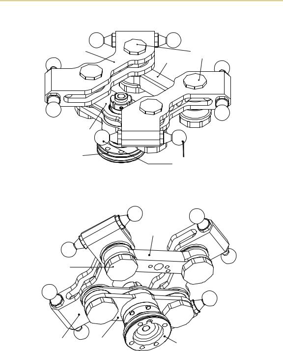
Ball Joints, Outer Arms
The inner arm motion is transmitted to the platform through the outer arms, which are connected between the inner arms and platform with precision ball-joints. The outer arms are carbon fiber epoxied assemblies with identical ball-joint sockets at each end. A bearing
insert at each socket accepts the ball-joint studs on the inner arms and platform, and allows for ± 60° of relative motion. No ball-joint lubrication is required. See Figure 1-5.
Ball Joint Socket
Ball Joint 
Socket Insert
Inner Arm
Outer
Arms
Outer
Arm
Springs
Ball Joint Stud
Figure 1-5. Ball Joints between Inner and Outer Arms
Each pair of outer arms is held together with springs that pretension the ball joint assemblies. The outer arms can be installed and removed without the need for tools.
Platform
The platform converts the motion of the four Quattro motors into Cartesian motion and Theta rotation of the robot tool.
Platform articulation is achieved by differentially driving the four motors. Tool rotation is implemented with either a belt-drive mechanism or with direct-drive, for applications needing higher rotation force but less rotation range.
The Adept Quattro s650 robot currently supports two types of platforms, depending on the amount of Theta rotation and inertia needed by the customer.
NOTE: The two platforms require different robot parameters. The 4:1 platform is the default. If you have a 1:1 platform, contact your Adept representative.
16 |
Adept Quattro s650 Robot User’s Guide, Rev B |

Product Description
The 4:1 platform (P/N 08360-000) has a rotation range of ± 180°, achieved with a belt drive. This is illustrated in Figure 1-6 and Figure 1-7.
The 1:1 platform (P/N 08660-000) has a rotation range of ± 50°. The tool flange is mounted
directly to the pivot link: it does not rotate in relation to the pivot link, so there is no idler pulley or belt involved. This is illustrated in Figure 1-8 and Figure 1-9.
Refer to “Rotation and Payload Inertia - Range” on page 92 for details on rotation and inertial loading of the platforms.
Both platforms are constructed such that the clocking of the platform relative to the robot base is critical. This is detailed in “Clocking the Platform to the Base” on page 46.
Adept Quattro s650 Robot User’s Guide, Rev B |
17 |

Chapter 1 - Introduction
Lateral |
Small Sealing |
Link x 2 |
Caps x 4 |
|
Trailing |
|
Link |
End-Effector |
|
|
Pivot Link |
|
Tool |
|
|
Flange |
|
|
Belt |
Tool |
|
|
Flange |
|
Ball Joint |
|
|
|
|
|
Studs x 8 |
|
Figure 1-6. 4:1 Platform, Top View |
|
Tool |
|
Idler Pulley |
|
Gear Segment |
|
Flange |
|
|
|
|
|
Belt |
Trailing |
|
|
||
Large |
Link |
Belt |
Sealing |
|
Clamp |
|
|
|
Caps x 4 |
|
|
Idler
Pulley
Lateral
Link x 2
End-Effector
Pivot Link
Tool Flange
Figure 1-7. 4:1 Platform, Bottom View
18 |
Adept Quattro s650 Robot User’s Guide, Rev B |
Product Description
Lateral |
Small Sealing |
Link x 2 |
Caps x 4 |
|
Trailing |
|
Link |
End-Effector
Pivot Link
Tool
Flange Ball Joint
Studs x 8
Figure 1-8. 1:1 Platform, Top View
Trailing
Link
Large
Sealing
Caps x 4
Lateral |
End-Effector |
|
Link x 2 |
Tool Flange |
|
|
Pivot Link |
|
Figure 1-9. 1:1 Platform, Bottom View
For shipping:
•The robot is disassembled, with the platform and outer arms removed.
•The platform is shipped pre-assembled as a unit.
The user will need to connect the outer arms between the inner arms and the platform to reassemble the robot. The outer-arm assemblies are interchangeable.
Any end-effectors and their vacuum lines and wiring are user-supplied.
Adept Quattro s650 Robot User’s Guide, Rev B |
19 |

Chapter 1 - Introduction
Adept SmartController CX
The SmartController is the foundation of Adept’s family of high-performance distributed motion and vision controllers. The SmartController is designed for use with:
•Adept Quattro robots
•Adept Cobra s-series robots
•Adept Viper s-series robots
•Adept Python linear modules
•Adept MotionBlox-10
•Adept sMI6 (SmartMotion)
The Adept SmartController CX supports an integrated vision option and a conveyor tracking option, as well as other options. It offers scalability and support for IEEE 1394-based digital I/O and general motion expansion modules. The IEEE 1394 interface is the backbone of the Adept SmartServo distributed servo network, which supports Adept products. The controller is commonly programmed through its Fast Ethernet port, which can be on a distributed network or directly connected to a PC for programming.
|
|
|
|
|
|
|
|
|
|
|
|
*S/N 3562-XXXXX* |
|
|
|
R |
|
|
|
|
|
CAMERA |
RS-232/TERM |
|
RS-422/485 |
|
|
|
|
|
|
|
|
|
|
|
|
|
|||
|
|
|
|
|
|
|
|
|
|
|
|
|
CX |
|
|
|
|
SmartServo |
IEEE-1394 |
|
|
|
|
|
rtController |
||
OK |
HPE |
LAN |
|
|
|
|
Device Net |
Eth 10/100 |
|
|
|
|
|
SW1 |
1.1 |
1.2 |
2.1 |
2.2 |
BELT ENCODER |
RS-232-1 |
|
RS-232-2 |
|
||||
SF |
ES |
HD |
1 2 3 4 |
|
|
|
|
|
|
|
|
|
|
|
|
|
ON |
|
|
|
|
|
|
|
|
|
|
|
|
|
OFF |
|
|
|
|
|
|
|
|
|
|
1 |
2 |
3 |
|
|
|
|
|
|
|
|
|
|
a |
|
|
|
|
|
|
|
|
|
|
Sm |
|||
|
|
|
XDIO |
|
|
|
XUSR |
XSYS |
XFP |
XMCP |
XDC1 XDC2 |
||
|
|
|
|
|
|
|
|
|
|
|
24V |
5A |
|
|
|
|
|
|
|
|
|
|
|
|
-+ |
-+ |
|
Figure 1-10. Adept SmartController CX
Refer to Adept SmartController User’s Guide for detailed SmartController specifications.
1.2Installation Overview
The system installation process is summarized in the following table. Refer also to the system cable diagram in Figure 4-1 on page 51.
Table 1-1. Installation Overview
Task to be Performed |
Reference Location |
|
|
|
|
|
|
|
1. |
Mount the robot to a level, stable mounting frame. |
See Section 3.6 on page 41. |
|
|
|
2. |
Attach the robot outer arms and platform |
See Section 3.7 on page 46. |
|
|
|
3. |
Install the SmartController, Front Panel, T1 Manual |
See Section 4.3 on page 52. |
|
Control Pendant (MCP) (if purchased), and |
|
|
AdeptWindows user interface. |
|
|
|
|
20 |
Adept Quattro s650 Robot User’s Guide, Rev B |
|
|
|
Manufacturer’s Declaration |
|
|
|
|
|
|
Table 1-1. Installation Overview |
|
|
|
|
|
|
Task to be Performed |
Reference Location |
|
|
|
|
|
|
|
|
|
|
4. |
Install the IEEE 1394 and XSYS cables between |
See Section 4.5 on page 54. |
|
|
the robot and SmartController. |
|
|
|
|
|
|
5. |
Create a 24 VDC cable and connect it between the |
See Section 4.6 on page 54. |
|
|
robot and the user-supplied 24 VDC power supply. |
|
|
|
|
|
|
6. |
Create a 200-240 VAC cable and connect it |
See Section 4.7 on page 57. |
|
|
between the robot and the facility AC power source. |
|
|
|
|
|
|
7. |
Install user-supplied safety barriers in the workcell. |
See Section 4.9 on page 62. |
|
|
|
|
|
8. |
Read Chapter 5 to learn about connecting digital |
See Section 5.5 on page 67. |
|
|
I/O through the XIO connector on the robot. |
|
|
|
|
|
|
9. Read Chapter 5 to learn about commissioning the |
See Section 5.6 on page 73. |
|
|
|
system, including system start-up and testing |
|
|
|
operation. |
|
|
|
|
|
|
10.Read Chapter 6 if you need to install optional |
See Section 6.1 on page 83. |
|
|
|
equipment, including end-effectors, user air and |
|
|
|
electrical lines, external equipment, solenoids, etc. |
|
|
|
|
|
1.3Manufacturer’s Declaration
The Manufacturer’s Declaration of Incorporation and Conformity for Adept robot systems can be found on the Adept Web site, in the Download Center of the Support section.
http://www.adept.com/support/downloads.asp
In the Download Types search box, select Regulatory Certificates to find the document, which you can then download.
1.4How Can I Get Help?
Refer to the How to Get Help Resource Guide (Adept P/N 00961-00700) for details on getting assistance with your Adept software and hardware. Additionally, you can access information sources on Adept’s corporate web site:
http://www.adept.com
Adept Quattro s650 Robot User’s Guide, Rev B |
21 |

Chapter 1 - Introduction
Related Manuals
This manual covers the installation, operation, and maintenance of an Adept Quattro s650 robot system. There are additional manuals that cover programming the system, reconfiguring installed components, and adding other optional components; see Table 1-2. These manuals are available on the Adept Document Library CD-ROM shipped with each system.
|
Table 1-2. Related Manuals |
|
|
Manual Title |
Description |
|
|
|
|
Adept SmartController User’s |
Contains complete information on the installation and operation |
Guide |
of the Adept SmartController and the optional sDIO product. |
|
|
AdeptWindows Installation |
Describes complex network installations, installation and use of |
Guide and AdeptWindows |
NFS server software, the AdeptWindows Offline Editor, and the |
Online Help |
AdeptWindows DDE software. |
|
|
Instructions for Adept Utility |
Describes the utility programs used for advanced system |
Programs |
configurations, system upgrades, file copying, and other system |
|
configuration procedures. |
|
|
V+ Operating System User’s |
Describes the V+ operating system, including disk file |
Guide |
operations, monitor commands, and monitor command |
|
programs. |
|
|
V+ Language User’s Guide |
Describes the V+ language and programming of an Adept |
|
control system. |
|
|
Adept T1 Pendant User’s |
Describes use of the optional T1 Manual Control Pendant. |
Guide |
|
|
|
Adept ACE User’s Guide |
Describes the use of the Adept ACE graphical system |
|
configuration application. |
|
|
Adept SmartMotion |
Describes the use of Adept Utilities, including SPEC. |
Developer’s Guide |
|
|
|
Adept Document Library
The Adept Document Library (ADL) contains documentation for Adept products. You can access the ADL from:
•the Adept Software CD shipped with your system
•the separate ADL CD shipped with your system
•the Adept web site. Select Document Library from the Adept home page. To go directly to the Adept Document Library, type the following URL into your browser:
http://www.adept.com/Main/KE/DATA/adept_search.htm
To locate information on a specific topic, use the Document Library search engine on the ADL main page. To view a list of available product documentation, select the Document Titles option.
22 |
Adept Quattro s650 Robot User’s Guide, Rev B |

Safety 2
2.1Warnings, Cautions, and Notes in Manual
There are six levels of special alert notation used in this manual. In descending order of importance, they are:
DANGER: This indicates an imminently hazardous electrical situation which, if not avoided, will result in death or serious injury.
DANGER: This indicates an imminently hazardous situation which, if not avoided, will result in death or serious injury.
WARNING: This indicates a potentially hazardous electrical situation which, if not avoided, could result in injury or major damage to the equipment.
WARNING: This indicates a potentially hazardous situation which, if not avoided, could result in injury or major damage to the equipment.
CAUTION: This indicates a situation which, if not avoided, could result in damage to the equipment.
NOTE: This provides supplementary information, emphasizes a point or procedure, or gives a tip for easier operation.
Adept Quattro s650 Robot User’s Guide, Rev B |
23 |

Chapter 2 - Safety
2.2Warning Labels on the Robot
Figure 2-1 shows the warning labels on the Adept Quattro s650 robot.
Figure 2-1. Electrical and Thermal Warning Labels on AIB Chassis
2.3Precautions and Required Safeguards
This manual must be read by all personnel who install, operate, or maintain Adept systems, or who work within or near the workcell.
WARNING: Adept Technology strictly prohibits installation, commissioning, or operation of an Adept robot without adequate safeguards according to applicable local and national standards. Installations in EU and EEA countries must comply with EN 775/ISO 10218, especially sections 5,6; EN 292-2; and EN 60204-1, especially section 13.
Safety Barriers
Safety barriers must be an integral part of robot workcell design. Adept systems are computer-controlled and may activate remote devices under program control at times or along paths not anticipated by personnel. It is critical that safeguards be in place to prevent personnel from entering the workcell whenever equipment power is present.
The robot system integrator, or end user, must ensure that adequate safeguards, safety barriers, light curtains, safety gates, safety floor mats, etc., will be installed. The robot
workcell must be designed according to the applicable local and national standards (see
Section 2.8 on page 31).
The safe distance to the robot depends on the height of the safety fence. The height and the distance of the safety fence from the robot must ensure that personnel cannot reach the danger zone of the robot.
24 |
Adept Quattro s650 Robot User’s Guide, Rev B |

Precautions and Required Safeguards
The Adept control system has features that aid the user in constructing system safeguards, including customer emergency stop circuitry and digital input and output lines. The emergency power-off circuitry is capable of switching external power systems, and can be interfaced to the appropriate user-supplied safeguards.
Impact and Trapping Points
Adept robots are capable of moving at high speeds. If a person is struck by a robot (impacted) or trapped (pinched), death or serious injury could occur. Robot configuration, joint speed, joint orientation, and attached payload all contribute to the total amount of energy available to cause injury.
DANGER: The robot system must be installed to avoid interference with buildings, structures, utilities, other machines and equipment that may create a trapping hazard or pinch points.
Instructions for Emergency Movement without Drive Power
In an emergency, when AC power is removed from the system but DC power is still
present, the arm can be moved manually. The brake release button must be pressed to enable arm movement. Refer to “Brake Release Button” on page 65.
Emergency Recovery Procedures
In an emergency, follow your internal procedures for emergency recovery of systems.
Additional Safety Information
The standards and regulations listed in this handbook contain additional guidelines for robot system installation, safeguarding, maintenance, testing, startup, and operator training. Table 2-1 lists some sources for the various standards.
Adept Quattro s650 Robot User’s Guide, Rev B |
25 |

Chapter 2 - Safety
Table 2-1. Sources for International Standards and Directives
SEMI International Standards |
|
American National Standards Institute (ANSI) |
3081 Zanker Road |
|
11 West 42nd Street, 13th Floor |
San Jose, CA 95134 |
|
New York, NY 10036 |
USA |
|
USA |
Phone: 408-943-6900 |
|
Phone 212-642-4900 |
Fax: 408-428-9600 |
|
Fax 212-398-0023 |
http://www.semi.org |
|
http://www.ansi.org |
|
|
|
Underwriters Laboratories Inc. |
|
BSI Group (British Standards) |
333 Pfingsten Road |
|
389 Chiswick High Road |
Northbrook, IL 60062-2096 USA |
|
London W4 4AL |
|
|
United Kingdom |
Phone: 847-272-8800 |
|
|
Fax: 847-272-8129 |
|
Phone +44 (0)20 8996 9000 |
http://www.ul.com/info/standard.htm |
|
Fax +44 (0)20 8996 7400 |
|
|
|
|
|
http://www.bsi-global.com |
|
|
|
Global Engineering Documents |
|
Document Center, Inc. |
15 Inverness Way East |
|
1504 Industrial Way, Unit 9 |
Englewood, CO 80112 |
|
Belmont, CA 94002 |
USA |
|
USA |
Phone 800-854-7179 |
|
Phone 415-591-7600 |
Fax 303-397-2740 |
|
Fax 415-591-7617 |
http://global.ihs.com |
|
http://www.document-center.com |
|
|
|
IEC, International Electrotechnical Commission |
|
Robotic Industries Association (RIA) |
Rue de Varembe 3 |
|
900 Victors Way |
PO Box 131 |
|
PO Box 3724 |
CH-1211 Geneva 20 |
|
Ann Arbor, MI 48106 |
Switzerland |
|
USA |
Phone +41 22 919-0211 |
|
Phone 313-994-6088 |
Fax +41 22 919-0300 |
|
Fax 313-994-3338 |
http://www.iec.ch |
|
http://www.robotics.org |
|
|
|
DIN, Deutsches Institut für Normung e.V. |
|
|
German Institute for Standardization |
|
|
Burggrafenstrasse 6 |
|
|
10787 Berlin |
|
|
Germany |
|
|
Phone.: +49 30 2601-0 |
|
|
Fax: +49 30 2601-1231 |
|
|
http://www.din.de |
|
|
http://www2.beuth.de/ (publishing) |
|
|
|
|
|
26 |
Adept Quattro s650 Robot User’s Guide, Rev B |

Risk Assessment
2.4Risk Assessment
Without special safeguards in its control system, the Adept Quattro s650 robot could inflict serious injury on an operator working within its work envelope. Safety standards in several countries require appropriate safety equipment to be installed as part of the system. Table 2-2 lists some of the safety standards that affect industrial robots. It is not a complete list. Safeguards must comply with all applicable local and national standards for the location where the robot is installed.
Table 2-2. Partial List of Robot and Machinery Safety Standards
International |
USA |
Canada |
Europe |
Title of Standard |
|
|
|
|
|
|
|
|
|
|
ISO 10218 |
|
|
EN 775 |
Manipulating Industrial Robots - |
|
|
|
|
Safety |
|
|
|
|
|
|
ANSI/RIA |
CAN/CSA- |
|
Industrial Robots and Robot |
|
R15.06 |
Z434-94 |
|
Systems - Safety Requirements |
|
|
|
|
|
|
|
|
EN 292-2 |
Safety of Machinery - Basic |
|
|
|
|
Concepts, General Principles for |
|
|
|
|
Design |
|
|
|
|
|
|
|
|
EN 954-1 |
Safety Related Parts of Control |
|
|
|
|
Systems - General Principles for |
|
|
|
|
Design |
|
|
|
|
|
|
|
|
EN 1050 |
Safety of Machinery - Risk |
|
|
|
|
Assessment |
|
|
|
|
|
Exposure
When Arm Power is ON, all personnel must be kept out of the robot work envelope by
interlocked perimeter barriers. The only permitted exception is for teaching the robot in Manual Mode by a skilled programmer (see “Qualification of Personnel” on page 32), who must wear safety equipment (see “Safety Equipment for Operators” on page 33) and carry
the T1 pendant. Therefore, exposure of personnel to hazards related to the robot is limited (seldom and/or short exposure time).
Severity of Injury
Provided that skilled personnel who enter the robot work envelope are wearing protective headgear, eyeglasses, and safety shoes, it is likely that any injuries caused by the robot would be slight (normally reversible).
Avoidance
A programmer must always carry the pendant when inside the work envelope, as the pendant provides both E-Stop and Enabling switch functions.
For normal operation (AUTO mode), user-supplied interlocked guarding must be installed to prevent any person entering the workcell while Arm Power is ON.
Adept Quattro s650 Robot User’s Guide, Rev B |
27 |

Chapter 2 - Safety
DANGER: The Adept-supplied system components provide a Category 3 E-Stop control system as defined by EN 954. The robot system must be installed with user-supplied interlock barriers. The interlocked barrier must open the E-Stop circuit in the event of personnel attempting to enter the workcell when Arm Power is enabled, except for teaching in Manual mode. Failure to install suitable guarding or interlocks could result in injury or death.
The E-stop circuit is Dual Channel (Redundant, Diverse, and Control Reliable).
See Figure 7-5 on page 89 for an E-stop internal circuit diagram.
Slow Speed Control Function and Testing
Adept robots can also be controlled manually when the operating mode key switch is in the MANUAL position and the HIGH POWER light on the Front Panel is illuminated. When Manual mode is selected, motion can only be initiated from the pendant (T1). Per EN 775/ISO 10218, the maximum speed of the robot is limited to 250 mm per second (10 ips) in Manual mode. It is important to remember that the robot speed is not limited when the robot is in Automatic (AUTO) mode.
The Risk Assessment for teaching this product depends on the application. In many applications, the programmer will need to enter the robot workcell while Arm Power is enabled to teach the robot. Other applications can be designed so that the programmer does not have to enter the work envelope while Arm Power is ON. Examples of alternative methods of programming include:
1.Programming from outside the safety barrier.
2.Programming with Arm Power OFF.
3.Copying a program from another (master) robot.
4.Off-line or CAD programming.
Control System Behavior Category
The following paragraphs relate to the requirements of European (EU/EEA) directives for Machinery, Electric Safety, and Electromagnetic Compatibility (EMC).
In situations with low exposure consideration factors, European Standard EN 1050 specifies use of a Category 1 Control System per EN 954. EN 954 defines a Category 1 Control System as one that employs Category B components designed to withstand environmental influences, such as voltage, current, temperature, EMI, and well-tried safety principles. The standard control system described in this guide employs hardware components in its safety system that meet or exceed the requirements of the EU Machinery Directive and Low Voltage Directive.
28 |
Adept Quattro s650 Robot User’s Guide, Rev B |

Intended Use of the Robots
The standard control system is fully hardened to all EMI influences per the EU EMC Directive and meets all functional requirements of ISO 10218 (EN 775) Manipulating Robots Safety. In addition, a software-based reduced speed mode has been incorporated to limit speed and impact forces on the operator and production tooling when the robot is operated in Manual Mode.
The standard control system meets or exceeds the requirements imposed by the EN 954 specified Category 1 level of safety.
2.5Intended Use of the Robots
The installation and use of Adept products must comply with all safety instructions and
warnings in this manual. Installation and use must also comply with all applicable local and national requirements and safety standards (see Section 2.8 on page 31).
The Adept Quattro s650 robot is intended for use in parts assembly and material handling for payloads less than 2.0 kg (4.4 lb).
The Adept Quattro s650 robot and the Adept SmartController are component subassemblies of a complete industrial automation system. The controller must be installed inside a suitable enclosure. The controller must not come into contact with liquids.
The Adept equipment is not intended for use in any of the following situations:
•In hazardous (explosive) atmospheres
•In mobile, portable, marine, or aircraft systems
•In life-support systems
•In residential installations
•In situations where the Adept equipment will be subject to extremes of heat or humidity. See Table 3-1 on page 38 for allowable temperature and humidity ranges.
WARNING: The instructions for installation, operation, and maintenance given in this User’s Guide must be strictly observed.
Non-intended use of an Adept Quattro s650 robot can:
•Cause injury to personnel
•Damage the robot or other equipment
•Reduce system reliability and performance
All persons that install, commission, operate, or maintain the robot must:
•Have the necessary qualifications
•Read and follow exactly the instructions in this User’s Guide
If there is any doubt concerning the application, ask Adept to determine if it is an intended use or not.
Adept Quattro s650 Robot User’s Guide, Rev B |
29 |

Chapter 2 - Safety
2.6Robot Modifications
It is sometimes necessary to modify the robot in order to successfully integrate it into a workcell. Unfortunately, many seemingly simple modifications can either cause a robot failure or reduce the robot’s performance, reliability, or lifetime. The following information is provided as a guideline to modifications.
WARNING: For safety reasons, it is prohibited to make certain modifications to Adept robots.
Acceptable Modifications
In general, the following robot modifications will not cause problems, but may affect robot performance:
•Attaching utility boxes, solenoid packs, vacuum pumps, cameras, lighting, etc., to the robot base.
•Attaching hoses, pneumatic lines, or cables to the robot. These should be designed so they do not restrict arm motion or cause robot motion errors.
•Attaching user tooling to the platform.
NOTE: Due to the kinematics of parallel robots, user cabling and tooling can have a significant effect on robot performance, and must be budgeted into the 2 kg payload rating of the Adept Quattro s650 robot. Significant consideration should be placed on symmetrically loading the platform, and not overloading one arm with respect to the others.
Unacceptable Modifications
The following modifications may damage the robot, reduce system safety and reliability, or shorten the life of the robot.
CAUTION: Making any of the modifications outlined below will void the warranty of any components that Adept determines were damaged due to the modification. You must contact Adept Customer Service if you are considering any of the following modifications.
•Modifying any of the robot harnesses or robot-to-controller cables.
•Modifying any robot access covers or drive system components.
•Modifying, including drilling or cutting, any robot casting.
•Modifying any robot electrical component or printed-circuit board.
•Modifications that compromise EMC performance, including shielding.
30 |
Adept Quattro s650 Robot User’s Guide, Rev B |
Loading...