


 Loading...
Adept Cobra
i600/i800 Robot
User’s Guide
Adept Cobra
i600/i800 Robot
User’s Guide
P/N: 03589-000, Rev G
December, 2011
5960 Inglewood Drive • Pleasanton, CA 94588 • USA • Phone 925.245.3400 • Fax 925.960.0452 Otto-Hahn-Strasse 23 • 44227 Dortmund • Germany • Phone +49.231.75.89.40 • Fax +49.231.75.89.450
Block 5000 Ang Mo Kio Avenue 5 • #05-12 Techplace II • Singapore 569870 • Phone +65.6755 2258 • Fax +65.6755 0598
The information contained herein is the property of Adept Technology, Inc., and shall not be reproduced in whole or in part without prior written approval of Adept Technology, Inc. The information herein is subject to change without notice and should not be construed as a commitment by Adept Technology, Inc. This manual is periodically reviewed and revised.
Adept Technology, Inc., assumes no responsibility for any errors or omissions in this document. Critical evaluation of this manual by the user is welcomed. Your comments assist us in preparation of future documentation. Please email your comments to: techpubs@adept.com.
Copyright 2002-2006, 2009-2011 by Adept Technology, Inc.
The Adept logo, AdeptVision, AIM, HexSight, and HexaVision are registered trademarks of Adept Technology, Inc.
Adept ACE, Adept Cobra i600, Adept Cobra i800, and MicroV+ are trademarks of Adept Technology, Inc.
Any trademarks from other companies used in this publication are the property of those respective companies.
Printed in the United States of America

Table of Contents
1 Introduction . . . . . . . . . . . . . . . . . . . . . . . . . . . . . . . . . . . . . . . . . . . . . . . |
11 |
1.1 Product Description. . . . . . . . . . . . . . . . . . . . . . . . . . . . . . . . . . . . . . . . . . . . . . . . 11
Adept Cobra i600/i800™ Robots . . . . . . . . . . . . . . . . . . . . . . . . . . . . . . . . . . 11 Adept Amps-in-Base (AIB™). . . . . . . . . . . . . . . . . . . . . . . . . . . . . . . . . . . . . . 12
1.2 Dangers, Warnings, Cautions, and Notes . . . . . . . . . . . . . . . . . . . . . . . . . . . . . . 13
1.3 Safety Precautions . . . . . . . . . . . . . . . . . . . . . . . . . . . . . . . . . . . . . . . . . . . . . . . . 13 1.4 What to Do in an Emergency Situation . . . . . . . . . . . . . . . . . . . . . . . . . . . . . . . . 14 1.5 Additional Safety Information . . . . . . . . . . . . . . . . . . . . . . . . . . . . . . . . . . . . . . . 14
Manufacturer’s Declaration of Compliance (MDOC) . . . . . . . . . . . . . . . . 14 Adept Robot Safety Guide. . . . . . . . . . . . . . . . . . . . . . . . . . . . . . . . . . . . . . . 14
1.6 Intended Use of the Robots . . . . . . . . . . . . . . . . . . . . . . . . . . . . . . . . . . . . . . . . . 14
1.7 Installation Overview . . . . . . . . . . . . . . . . . . . . . . . . . . . . . . . . . . . . . . . . . . . . . . 15
1.8 Manufacturer’s Declaration . . . . . . . . . . . . . . . . . . . . . . . . . . . . . . . . . . . . . . . . . 15
1.9 How Can I Get Help? . . . . . . . . . . . . . . . . . . . . . . . . . . . . . . . . . . . . . . . . . . . . . . 16
Related Manuals . . . . . . . . . . . . . . . . . . . . . . . . . . . . . . . . . . . . . . . . . . . . . . . 16
Adept Document Library . . . . . . . . . . . . . . . . . . . . . . . . . . . . . . . . . . . . . . . . 16
2 Robot Installation . . . . . . . . . . . . . . . . . . . . . . . . . . . . . . . . . . . . . . . . . . . 17
2.1 Transport and Storage . . . . . . . . . . . . . . . . . . . . . . . . . . . . . . . . . . . . . . . . . . . . . 17 2.2 Unpacking and Inspecting the Adept Equipment. . . . . . . . . . . . . . . . . . . . . . . 18
Before Unpacking . . . . . . . . . . . . . . . . . . . . . . . . . . . . . . . . . . . . . . . . . . . . . . 18
Upon Unpacking . . . . . . . . . . . . . . . . . . . . . . . . . . . . . . . . . . . . . . . . . . . . . . . 18
2.3 Repacking for Relocation. . . . . . . . . . . . . . . . . . . . . . . . . . . . . . . . . . . . . . . . . . . 18 2.4 Environmental and Facility Requirements . . . . . . . . . . . . . . . . . . . . . . . . . . . . . 19 2.5 Mounting the Robot . . . . . . . . . . . . . . . . . . . . . . . . . . . . . . . . . . . . . . . . . . . . . . . 19
Mounting Surface . . . . . . . . . . . . . . . . . . . . . . . . . . . . . . . . . . . . . . . . . . . . . . 19
Robot Mounting Procedure . . . . . . . . . . . . . . . . . . . . . . . . . . . . . . . . . . . . . . 20
2.6 Connectors on the Robot Interface Panel . . . . . . . . . . . . . . . . . . . . . . . . . . . . . 22
3 System Installation . . . . . . . . . . . . . . . . . . . . . . . . . . . . . . . . . . . . . . . . . . 23
3.1 Cable and Parts List. . . . . . . . . . . . . . . . . . . . . . . . . . . . . . . . . . . . . . . . . . . . . . . . 23 3.2 System Cable Diagram . . . . . . . . . . . . . . . . . . . . . . . . . . . . . . . . . . . . . . . . . . . . 24 3.3 Cable Connections to the Robot. . . . . . . . . . . . . . . . . . . . . . . . . . . . . . . . . . . . . 25
Installing AIB XPANEL Cable . . . . . . . . . . . . . . . . . . . . . . . . . . . . . . . . . . . . . . 25
Installing Peripherals and Options . . . . . . . . . . . . . . . . . . . . . . . . . . . . . . . . . 25
Adept Cobra i600/i800 Robot User’s Guide, Rev G |
5 |

3.4 Connecting User-Supplied PC to Robot. . . . . . . . . . . . . . . . . . . . . . . . . . . . . . . . 25
PC Requirements. . . . . . . . . . . . . . . . . . . . . . . . . . . . . . . . . . . . . . . . . . . . . . . . 26
Installing Serial Cable . . . . . . . . . . . . . . . . . . . . . . . . . . . . . . . . . . . . . . . . . . . . 26
3.5 Installing Adept ACE Software . . . . . . . . . . . . . . . . . . . . . . . . . . . . . . . . . . . . . . . 26
3.6 Connecting 24 VDC Power to Robot . . . . . . . . . . . . . . . . . . . . . . . . . . . . . . . . . . 29
Specifications for 24 VDC Power . . . . . . . . . . . . . . . . . . . . . . . . . . . . . . . . . . 29 Connecting 24 VDC . . . . . . . . . . . . . . . . . . . . . . . . . . . . . . . . . . . . . . . . . . . . . 30
3.7 Connecting 200-240 VAC Power to Robot . . . . . . . . . . . . . . . . . . . . . . . . . . . . . 31
Specifications for AC Power . . . . . . . . . . . . . . . . . . . . . . . . . . . . . . . . . . . . . . 31 Details for AC Mating Connector . . . . . . . . . . . . . . . . . . . . . . . . . . . . . . . . . 33 Procedure for Creating 200-240 VAC Cable . . . . . . . . . . . . . . . . . . . . . . . . 34 Installing AC Power Cable to Robot . . . . . . . . . . . . . . . . . . . . . . . . . . . . . . . 34
3.8 Grounding the Adept Robot System . . . . . . . . . . . . . . . . . . . . . . . . . . . . . . . . . . 34
Ground Point on Robot Base . . . . . . . . . . . . . . . . . . . . . . . . . . . . . . . . . . . . . 35 Robot-Mounted Equipment Grounding . . . . . . . . . . . . . . . . . . . . . . . . . . . . 35
3.9 Installing User-Supplied Safety Equipment . . . . . . . . . . . . . . . . . . . . . . . . . . . . . 35
4 System Operation . . . . . . . . . . . . . . . . . . . . . . . . . . . . . . . . . . . . . . . . . . 37
4.1 Robot Status LED . . . . . . . . . . . . . . . . . . . . . . . . . . . . . . . . . . . . . . . . . . . . . . . . . . . 37
4.2 Status Panel Fault Codes . . . . . . . . . . . . . . . . . . . . . . . . . . . . . . . . . . . . . . . . . . . . 37
4.3 Using the Brake Release Button . . . . . . . . . . . . . . . . . . . . . . . . . . . . . . . . . . . . . . 39
Brakes . . . . . . . . . . . . . . . . . . . . . . . . . . . . . . . . . . . . . . . . . . . . . . . . . . . . . . . . 39
Brake Release Button . . . . . . . . . . . . . . . . . . . . . . . . . . . . . . . . . . . . . . . . . . . . 39
4.4 Front Panel . . . . . . . . . . . . . . . . . . . . . . . . . . . . . . . . . . . . . . . . . . . . . . . . . . . . . . . 40 4.5 Connecting Digital I/O to the System . . . . . . . . . . . . . . . . . . . . . . . . . . . . . . . . . 41 4.6 Using Digital I/O on Robot XIO Connector . . . . . . . . . . . . . . . . . . . . . . . . . . . . . 43
XIO Connector . . . . . . . . . . . . . . . . . . . . . . . . . . . . . . . . . . . . . . . . . . . . . . . . . 43
XIO Input Signals . . . . . . . . . . . . . . . . . . . . . . . . . . . . . . . . . . . . . . . . . . . . . . . . 44
XIO Output Signals . . . . . . . . . . . . . . . . . . . . . . . . . . . . . . . . . . . . . . . . . . . . . . 46
XIO Breakout Cable . . . . . . . . . . . . . . . . . . . . . . . . . . . . . . . . . . . . . . . . . . . . . 47
4.7 Connecting Customer-Supplied Safety and Power Control Equipment . . . . . 49
Connecting Equipment to the System . . . . . . . . . . . . . . . . . . . . . . . . . . . . . . 49 Emergency Stop Circuits . . . . . . . . . . . . . . . . . . . . . . . . . . . . . . . . . . . . . . . . . 53 Remote Manual Mode. . . . . . . . . . . . . . . . . . . . . . . . . . . . . . . . . . . . . . . . . . . 54 Remote High Power On/Off Control. . . . . . . . . . . . . . . . . . . . . . . . . . . . . . . . 54 High Power On/Off Lamp . . . . . . . . . . . . . . . . . . . . . . . . . . . . . . . . . . . . . . . . 55 Remote Front Panel or User-Supplied Replacement . . . . . . . . . . . . . . . . . . 55
6 |
Adept Cobra i600/i800 Robot User’s Guide, Rev G |

4.8 Turning On the System . . . . . . . . . . . . . . . . . . . . . . . . . . . . . . . . . . . . . . . . . . . . . 55
Verifying Installation . . . . . . . . . . . . . . . . . . . . . . . . . . . . . . . . . . . . . . . . . . . . 55 Turning on Power and Starting Adept ACE . . . . . . . . . . . . . . . . . . . . . . . . . 56 Enabling High Power . . . . . . . . . . . . . . . . . . . . . . . . . . . . . . . . . . . . . . . . . . . . 57 Verifying E-Stop Functions . . . . . . . . . . . . . . . . . . . . . . . . . . . . . . . . . . . . . . . . 60
4.9 Learning to Program the Adept Cobra i-Series Robot. . . . . . . . . . . . . . . . . . . . 60
5 Maintenance . . . . . . . . . . . . . . . . . . . . . . . . . . . . . . . . . . . . . . . . . . . . . . 61
5.1 Field-replaceable Parts . . . . . . . . . . . . . . . . . . . . . . . . . . . . . . . . . . . . . . . . . . . . 61
5.2 Periodic Maintenance Schedule. . . . . . . . . . . . . . . . . . . . . . . . . . . . . . . . . . . . . 61
5.3 Checking Safety Systems. . . . . . . . . . . . . . . . . . . . . . . . . . . . . . . . . . . . . . . . . . . 62
5.4 Checking Robot Mounting Bolt Torque . . . . . . . . . . . . . . . . . . . . . . . . . . . . . . . . 62
5.5 Checking Robot for Oil Around Harmonic Drive . . . . . . . . . . . . . . . . . . . . . . . . 62
5.6 Lubricating Joint 3 Ball Screw/Spline . . . . . . . . . . . . . . . . . . . . . . . . . . . . . . . . . 63
Required Grease for the Robot . . . . . . . . . . . . . . . . . . . . . . . . . . . . . . . . . . . 63 Lubrication Procedure. . . . . . . . . . . . . . . . . . . . . . . . . . . . . . . . . . . . . . . . . . . 63
5.7 Replacing the AIB Chassis . . . . . . . . . . . . . . . . . . . . . . . . . . . . . . . . . . . . . . . . . . 65
Removing the AIB Chassis . . . . . . . . . . . . . . . . . . . . . . . . . . . . . . . . . . . . . . . . 65 Installing a New AIB Chassis . . . . . . . . . . . . . . . . . . . . . . . . . . . . . . . . . . . . . . 67
5.8 Replacing Encoder Battery . . . . . . . . . . . . . . . . . . . . . . . . . . . . . . . . . . . . . . . . . 69
Battery Replacement Time Periods . . . . . . . . . . . . . . . . . . . . . . . . . . . . . . . . 69
Battery Replacement Procedure. . . . . . . . . . . . . . . . . . . . . . . . . . . . . . . . . . 69
6 Optional Equipment Installation . . . . . . . . . . . . . . . . . . . . . . . . . . . . . . . 71
6.1 Installing End-Effectors . . . . . . . . . . . . . . . . . . . . . . . . . . . . . . . . . . . . . . . . . . . . . 71
6.2 Removing and Installing the Tool Flange . . . . . . . . . . . . . . . . . . . . . . . . . . . . . . 71
Removing the Flange . . . . . . . . . . . . . . . . . . . . . . . . . . . . . . . . . . . . . . . . . . . 71
Installing the Flange. . . . . . . . . . . . . . . . . . . . . . . . . . . . . . . . . . . . . . . . . . . . . 72
6.3 User Connections on the Robot . . . . . . . . . . . . . . . . . . . . . . . . . . . . . . . . . . . . . . 72
User Air Lines . . . . . . . . . . . . . . . . . . . . . . . . . . . . . . . . . . . . . . . . . . . . . . . . . . . 72
User Electrical Lines . . . . . . . . . . . . . . . . . . . . . . . . . . . . . . . . . . . . . . . . . . . . . 73
6.4 Internal User Connectors . . . . . . . . . . . . . . . . . . . . . . . . . . . . . . . . . . . . . . . . . . . 74
SOLND Connector . . . . . . . . . . . . . . . . . . . . . . . . . . . . . . . . . . . . . . . . . . . . . 75
OP3/4 Connector . . . . . . . . . . . . . . . . . . . . . . . . . . . . . . . . . . . . . . . . . . . . . . 75
EOAPWR Connector . . . . . . . . . . . . . . . . . . . . . . . . . . . . . . . . . . . . . . . . . . . . 76
Internal User Connector Output Specifications . . . . . . . . . . . . . . . . . . . . . 77
ESTOP Connector . . . . . . . . . . . . . . . . . . . . . . . . . . . . . . . . . . . . . . . . . . . . . . 77
Adept Cobra i600/i800 Robot User’s Guide, Rev G |
7 |

6.5 Mounting Locations for External Equipment . . . . . . . . . . . . . . . . . . . . . . . . . . . . 79
6.6 Installing the Robot Solenoid Kit . . . . . . . . . . . . . . . . . . . . . . . . . . . . . . . . . . . . . . 79
Introduction . . . . . . . . . . . . . . . . . . . . . . . . . . . . . . . . . . . . . . . . . . . . . . . . . . . . 79
Tools Required . . . . . . . . . . . . . . . . . . . . . . . . . . . . . . . . . . . . . . . . . . . . . . . . . . 80
Procedure . . . . . . . . . . . . . . . . . . . . . . . . . . . . . . . . . . . . . . . . . . . . . . . . . . . . . 80
6.7 Installing Adjustable Hardstops . . . . . . . . . . . . . . . . . . . . . . . . . . . . . . . . . . . . . . 84
Joint 1 Adjustable Hardstops . . . . . . . . . . . . . . . . . . . . . . . . . . . . . . . . . . . . . 84
Joint 2 Adjustable Hardstops . . . . . . . . . . . . . . . . . . . . . . . . . . . . . . . . . . . . . 86
7 Technical Specifications . . . . . . . . . . . . . . . . . . . . . . . . . . . . . . . . . . . . . 91
7.1 Dimension Drawings . . . . . . . . . . . . . . . . . . . . . . . . . . . . . . . . . . . . . . . . . . . . . . . 91
7.2 Robot Specifications . . . . . . . . . . . . . . . . . . . . . . . . . . . . . . . . . . . . . . . . . . . . . . . 99
8 Cleanroom Robots . . . . . . . . . . . . . . . . . . . . . . . . . . . . . . . . . . . . . . . . . 101
8.1 Cobra i600/i800 Cleanroom Option . . . . . . . . . . . . . . . . . . . . . . . . . . . . . . . . . 101
Introduction . . . . . . . . . . . . . . . . . . . . . . . . . . . . . . . . . . . . . . . . . . . . . . . . . . . 101
Specifications . . . . . . . . . . . . . . . . . . . . . . . . . . . . . . . . . . . . . . . . . . . . . . . . . 102
8.2 Connections . . . . . . . . . . . . . . . . . . . . . . . . . . . . . . . . . . . . . . . . . . . . . . . . . . . . . 102
8.3 Requirements . . . . . . . . . . . . . . . . . . . . . . . . . . . . . . . . . . . . . . . . . . . . . . . . . . . . 102
8.4 Exclusions and Incompatibilities . . . . . . . . . . . . . . . . . . . . . . . . . . . . . . . . . . . . 103
8.5 Maintenance . . . . . . . . . . . . . . . . . . . . . . . . . . . . . . . . . . . . . . . . . . . . . . . . . . . . 103
Bellows Replacement . . . . . . . . . . . . . . . . . . . . . . . . . . . . . . . . . . . . . . . . . . 103
Lubrication . . . . . . . . . . . . . . . . . . . . . . . . . . . . . . . . . . . . . . . . . . . . . . . . . . . 104
8 |
Adept Cobra i600/i800 Robot User’s Guide, Rev G |

|
List of Figures |
|
Figure 1-1. |
Adept Cobra i800 Robot . . . . . . . . . . . . . . . . . . . . . . . . . . . . . . . . . . . . . . . . . |
11 |
Figure 1-2. |
Robot Joint Motions . . . . . . . . . . . . . . . . . . . . . . . . . . . . . . . . . . . . . . . . . . . . . |
12 |
Figure 1-3. |
Adept AIB . . . . . . . . . . . . . . . . . . . . . . . . . . . . . . . . . . . . . . . . . . . . . . . . . . . . . . |
12 |
Figure 2-1. |
Cobra Robot on a Transportation Pallet . . . . . . . . . . . . . . . . . . . . . . . . . . . . |
17 |
Figure 2-2. |
Mounting Hole Pattern for Robot . . . . . . . . . . . . . . . . . . . . . . . . . . . . . . . . . . |
20 |
Figure 2-3. |
Robot Interface Panel . . . . . . . . . . . . . . . . . . . . . . . . . . . . . . . . . . . . . . . . . . . |
22 |
Figure 3-1. |
iCobra System Cable Diagram . . . . . . . . . . . . . . . . . . . . . . . . . . . . . . . . . . . . |
24 |
Figure 3-2. |
Adept ACE CD-ROM Startup Menu . . . . . . . . . . . . . . . . . . . . . . . . . . . . . . . . |
27 |
Figure 3-3. |
Setup Welcome Screen . . . . . . . . . . . . . . . . . . . . . . . . . . . . . . . . . . . . . . . . . . |
27 |
Figure 3-4. |
Ready-to-Install Screen . . . . . . . . . . . . . . . . . . . . . . . . . . . . . . . . . . . . . . . . . . . |
27 |
Figure 3-5. |
Install Screen . . . . . . . . . . . . . . . . . . . . . . . . . . . . . . . . . . . . . . . . . . . . . . . . . . . |
28 |
Figure 3-6. |
Installation Completed . . . . . . . . . . . . . . . . . . . . . . . . . . . . . . . . . . . . . . . . . . . |
28 |
Figure 3-7. |
User-Supplied 24 VDC Cable . . . . . . . . . . . . . . . . . . . . . . . . . . . . . . . . . . . . . . |
31 |
Figure 3-8. |
Typical AC Power Installation with Single-Phase Supply . . . . . . . . . . . . . . . . |
33 |
Figure 3-9. |
Single-Phase Load across L1 and L2 of a Three-Phase AC Supply . . . . . . . |
33 |
Figure 3-10. |
AC Power Mating Connector . . . . . . . . . . . . . . . . . . . . . . . . . . . . . . . . . . . . . |
34 |
Figure 3-11. |
Ground Point on Robot Base . . . . . . . . . . . . . . . . . . . . . . . . . . . . . . . . . . . . . . |
35 |
Figure 4-1 |
Robot Status LED Indicator Location . . . . . . . . . . . . . . . . . . . . . . . . . . . . . . . |
37 |
Figure 4-2 |
Status Panel . . . . . . . . . . . . . . . . . . . . . . . . . . . . . . . . . . . . . . . . . . . . . . . . . . . . |
38 |
Figure 4-3 |
Front Panel . . . . . . . . . . . . . . . . . . . . . . . . . . . . . . . . . . . . . . . . . . . . . . . . . . . . . |
40 |
Figure 4-4 |
Connecting Digital I/O to the System . . . . . . . . . . . . . . . . . . . . . . . . . . . . . . . |
42 |
Figure 4-5 |
Typical User Wiring for XIO Input Signals . . . . . . . . . . . . . . . . . . . . . . . . . . . . . |
45 |
Figure 4-6 |
Typical User Wiring for XIO Output Signals . . . . . . . . . . . . . . . . . . . . . . . . . . . |
47 |
Figure 4-7 |
Optional XIO Breakout Cable . . . . . . . . . . . . . . . . . . . . . . . . . . . . . . . . . . . . . |
47 |
Figure 4-8 |
Cobra i600/i800 E-Stop Circuit Connections . . . . . . . . . . . . . . . . . . . . . . . . . |
52 |
Figure 4-9 |
Front Panel Schematic . . . . . . . . . . . . . . . . . . . . . . . . . . . . . . . . . . . . . . . . . . . |
53 |
Figure 4-10 |
Adept ACE Startup Menu . . . . . . . . . . . . . . . . . . . . . . . . . . . . . . . . . . . . . . . . |
57 |
Figure 4-11 |
Connecting to the iCobra . . . . . . . . . . . . . . . . . . . . . . . . . . . . . . . . . . . . . . . . |
57 |
Figure 4-12 |
High Power and Launch Robot Jog Control Icons . . . . . . . . . . . . . . . . . . . . |
58 |
Figure 4-13 |
Robot Jog Control Window . . . . . . . . . . . . . . . . . . . . . . . . . . . . . . . . . . . . . . . |
59 |
Figure 4-14 |
Jog Pendant Menu . . . . . . . . . . . . . . . . . . . . . . . . . . . . . . . . . . . . . . . . . . . . . . |
60 |
Figure 5-1. |
Lubrication of Joint 3 Quill . . . . . . . . . . . . . . . . . . . . . . . . . . . . . . . . . . . . . . . . |
64 |
Figure 5-2. |
Securing Screw on AIB Chassis . . . . . . . . . . . . . . . . . . . . . . . . . . . . . . . . . . . . |
65 |
Figure 5-3. |
Opening and Removing AIB Chassis . . . . . . . . . . . . . . . . . . . . . . . . . . . . . . . |
66 |
Figure 5-4. |
Connectors on AIB Chassis . . . . . . . . . . . . . . . . . . . . . . . . . . . . . . . . . . . . . . . . |
66 |
Figure 5-5. |
Ground Screw on AIB Chassis . . . . . . . . . . . . . . . . . . . . . . . . . . . . . . . . . . . . . |
67 |
Figure 5-6. |
Installing AIB Chassis in Robot Base . . . . . . . . . . . . . . . . . . . . . . . . . . . . . . . . . |
68 |
Figure 5-7. |
Location of Encoder Battery Pack . . . . . . . . . . . . . . . . . . . . . . . . . . . . . . . . . |
70 |
Figure 6-1. |
Tool Flange Removal Details . . . . . . . . . . . . . . . . . . . . . . . . . . . . . . . . . . . . . . |
72 |
Adept Cobra i600/i800 Robot User’s Guide, Rev G |
9 |

Figure 6-2. |
User Connectors on Joint 1 . . . . . . . . . . . . . . . . . . . . . . . . . . . . . . . . . . . . . . . |
. 73 |
Figure 6-3. |
User Connectors on Joint 2 . . . . . . . . . . . . . . . . . . . . . . . . . . . . . . . . . . . . . . . . |
73 |
Figure 6-4. |
Internal User Connectors - OP3/4, EOAPWR, ESTOP . . . . . . . . . . . . . . . . . . . . |
74 |
Figure 6-5. |
SOLND Connector . . . . . . . . . . . . . . . . . . . . . . . . . . . . . . . . . . . . . . . . . . . . . . . |
74 |
Figure 6-6. |
OP3/4 and SOLND Circuits . . . . . . . . . . . . . . . . . . . . . . . . . . . . . . . . . . . . . . . . |
76 |
Figure 6-7. |
Internal E-Stop Connector Circuit . . . . . . . . . . . . . . . . . . . . . . . . . . . . . . . . . . |
78 |
Figure 6-8. |
Selecting the Configuration Manager . . . . . . . . . . . . . . . . . . . . . . . . . . . . . . |
78 |
Figure 6-9. |
Solenoid Mounting Bracket with Connector and Spare Air Line . . . . . . . . . |
81 |
Figure 6-10. |
Solenoid Placement Using Mounting Hardware . . . . . . . . . . . . . . . . . . . . . . |
82 |
Figure 6-11. |
Removing the Cable Strap Plate . . . . . . . . . . . . . . . . . . . . . . . . . . . . . . . . . . . |
82 |
Figure 6-12. |
Connecting Spare Air Line to User Connector . . . . . . . . . . . . . . . . . . . . . . . . |
83 |
Figure 6-13. |
Joint 1 Adjustable Hardstops . . . . . . . . . . . . . . . . . . . . . . . . . . . . . . . . . . . . . . |
84 |
Figure 6-14. |
Configuration Manager - Modifying Joint 1 Limits . . . . . . . . . . . . . . . . . . . . . |
85 |
Figure 6-15. |
Configuration Manager - Apply Changes . . . . . . . . . . . . . . . . . . . . . . . . . . . |
86 |
Figure 6-16. |
Joint 2 Hardstop Kit . . . . . . . . . . . . . . . . . . . . . . . . . . . . . . . . . . . . . . . . . . . . . . |
86 |
Figure 6-17. |
Joint 2 Adjustable Hardstop Locations . . . . . . . . . . . . . . . . . . . . . . . . . . . . . . |
87 |
Figure 6-18. |
Fixed Hardstop Device for Joint 2 . . . . . . . . . . . . . . . . . . . . . . . . . . . . . . . . . . |
87 |
Figure 6-19. |
Screw Locations for Joint 2 Adjustable Hardstops . . . . . . . . . . . . . . . . . . . . . |
88 |
Figure 6-20. |
Configuration Manager - Modifying Joint 2 Limits . . . . . . . . . . . . . . . . . . . . . |
89 |
Figure 7-1. |
Adept Cobra i600/s600 Top and Side Dimensions . . . . . . . . . . . . . . . . . . . . . |
91 |
Figure 7-2. |
Adept Cobra i800/s800 Top and Side Dimensions . . . . . . . . . . . . . . . . . . . . . |
92 |
Figure 7-3. |
Dimensions of the Camera Bracket Mounting Pattern . . . . . . . . . . . . . . . . . |
93 |
Figure 7-4. |
Tool Flange Dimensions . . . . . . . . . . . . . . . . . . . . . . . . . . . . . . . . . . . . . . . . . . . |
94 |
Figure 7-5. |
External Tooling on Top of Robot Arm . . . . . . . . . . . . . . . . . . . . . . . . . . . . . . . |
95 |
Figure 7-6. |
External Tooling on Underside of Outer Link . . . . . . . . . . . . . . . . . . . . . . . . . . |
96 |
Figure 7-7. |
Adept Cobra i600/s600 Robot Working Envelope . . . . . . . . . . . . . . . . . . . . . |
97 |
Figure 7-8. |
Adept Cobra i800/s800 Robot Working Envelope . . . . . . . . . . . . . . . . . . . . . |
98 |
Figure 8-1. |
Adept Cobra i600 Cleanroom Robot . . . . . . . . . . . . . . . . . . . . . . . . . . . . . . |
101 |
Figure 8-2. |
Cleanroom Connections . . . . . . . . . . . . . . . . . . . . . . . . . . . . . . . . . . . . . . . . |
102 |
Figure 8-3. |
Cleanroom Bellows Replacement . . . . . . . . . . . . . . . . . . . . . . . . . . . . . . . . . |
104 |
10 |
Adept Cobra i600/i800 Robot User’s Guide, Rev G |
Introduction 1
1.1Product Description
Adept Cobra i600/i800™ Robots
The Adept Cobra i600 and i800 robots are four-axis SCARA robots (Selective Compliance Assembly Robot Arm). See the following figure. Joints 1, 2, and 4 are rotational; Joint 3 is translational. See Figure 1-2 for a description of the robot joint locations.
The Adept Cobra i-series robots are programmed and controlled using Adept ACE™ software, running on a user-supplied PC. Mechanical specifications for the Adept Cobra i-series robots are provided in Chapter 7.
NOTE: The descriptions and instructions in this manual apply to both the Cobra i600 and the Cobra i800, except for instances where there is a difference, as in dimension and work envelope drawings. In those cases the information is presented for both robots.
Figure 1-1. Adept Cobra i800 Robot
Adept Cobra i600/i800 Robot User’s Guide, Rev G |
11 |

Introduction
Joint 2


 Joint 1
Joint 3
|
Outer |
|
Inner |
Link |
|
Joint 4 |
||
Link |
Figure 1-2. Robot Joint Motions
Adept Amps-in-Base (AIB™)
The amplifiers for the Adept Cobra i-series robots are embedded in the base of the robot. This amplifier section is known as the AIB (amp-in-base). It provides power amplifiers and full servo control.
Adept AIB features:
•On-board digital I/O
•Low EMI for use with noise-sensitive equipment
•No external fan for quiet robot operation
•8 kHz servo rate delivers low positional errors and superior path following
•Sine wave commutation lowers cogging torque and improves path following
•Digital feed-forward design maximizes efficiency, torque, and velocity
•Temperature sensors for all amplifiers and motors for maximum reliability and easy troubleshooting
AIB on Adept Cobra i600 Robot
Figure 1-3. Adept AIB
12 |
Adept Cobra i600/i800 Robot User’s Guide, Rev G |

Dangers, Warnings, Cautions, and Notes
1.2Dangers, Warnings, Cautions, and Notes
There are six levels of special alert notation used in Adept manuals. In descending order of importance, they are:
DANGER: This indicates an imminently hazardous electrical situation which, if not avoided, will result in death or serious injury.
DANGER: This indicates an imminently hazardous situation which, if not avoided, will result in death or serious injury.
WARNING: This indicates a potentially hazardous electrical situation which, if not avoided, could result in injury or major damage to the equipment.
WARNING: This indicates a potentially hazardous situation which, if not avoided, could result in injury or major damage to the equipment.
CAUTION: This indicates a situation which, if not avoided, could result in damage to the equipment.
NOTE: Notes provide supplementary information, emphasize a point or procedure, or give a tip for easier operation.
1.3Safety Precautions
DANGER: An Adept Cobra i600/i800 robot can cause serious injury or death, or damage to itself and other equipment, if the following safety precautions are not observed:
•All personnel who install, operate, teach, program, or maintain the system must read this guide, read the Adept Robot Safety Guide, and complete a training course for their respo nsibilities in regard to the robot.
•All personnel who design the robot system must read this guide, read the Adept Robot Safety Guide, and must comply with all local and national safety regulations for the location in which the robot is installed.
Adept Cobra i600/i800 Robot User’s Guide, Rev G |
13 |

Introduction
•The robot system must not be used for purposes other than described in Section 1.6. Contact Adept if you are not sure of the suitability for your application.
•The user is responsible for providing safety barriers around the robot to prevent anyone from accidentally coming into contact with the robot when it is in motion.
•Power to the robot and its power supply must be locked out and tagged out before any maintenance is performed.
1.4What to Do in an Emergency Situation
Press any E-Stop button (a red push-button on a yellow background/field) and then follow the internal procedures of your company or organization for an emergency situation. If a fire occurs, use CO2 to extinguish the fire.
1.5Additional Safety Information
Adept provides other sources for more safety information:
Manufacturer’s Declaration of Compliance (MDOC)
This lists all standards with which each robot complies. See “Manufacturer’s
Declaration” on page 15.
Adept Robot Safety Guide
The Adept Robot Safety Guide provides detailed information on safety for Adept robots. It also gives resources for more information on relevant standards.
It ships with each robot manual, and is also available from the Adept Document Library.
See “Adept Document Library” on page 16.
1.6Intended Use of the Robots
The Adept Cobra i600 and i800 robots are intended for use in parts assembly and material handling for payloads less than 5.5 kg (12.1 lb).
14 |
Adept Cobra i600/i800 Robot User’s Guide, Rev G |

Installation Overview
1.7Installation Overview
The system installation process is summarized in the following table. Refer also to the system cable diagram in Figure 3-1 on page 24.
NOTE: The Adept Cobra i600/i800 Robot Quick Setup Guide provides abbreviated instructions on installing your robot system.
Table 1-1. Installation Overview
Task to be Performed |
Reference Location |
|
|
|
|
|
|
|
1. |
Mount the robot on a flat, secure mounting surface. |
See Section 2.5 on page 19. |
|
|
|
2. |
Install the system cables and options. |
See Section 3.3 on page 25. |
|
|
|
3. |
Connect the PC to the robot. |
See Section 3.4 on page 25. |
|
|
|
4. |
Install Adept ACE software on the PC. |
See the Adept Cobra |
|
|
i600/i800 Robot Quick Setup |
|
|
Guide. |
|
|
|
5. |
Create a 24 VDC cable and connect it between the |
See Section 3.6 on page 29. |
|
robot and the 24 VDC power supply. |
|
|
|
|
6. |
Create a 200-240 VAC cable and connect it |
See Section 3.7 on page 31. |
|
between the robot and the facility AC power source. |
|
|
|
|
7. |
Install user-supplied safety barriers in the workcell. |
See Section 3.9 on page 35. |
|
|
|
8. |
Read Chapter 4 to learn about connecting digital I/O |
See Section 4.5 on page 41. |
|
through the XIO connector on the robot. |
|
|
|
|
9. |
Read Chapter 4 to learn about turning on the |
See Section 4.8 on page 55. |
|
system and testing operation. |
|
|
|
|
10.Read Chapter 6 if you need to install optional |
See Section 6.1 on page 71. |
|
|
equipment, including end-effectors, user air and |
|
|
electrical lines, external equipment, solenoids, etc. |
|
|
|
|
1.8Manufacturer’s Declaration
The Manufacturer’s Declaration of Incorporation and Conformity lists all standards with which the Adept robot system complies. It can be found on the Adept Web site, in the Download Center of the Support section.
ftp://ftp1.adept.com/Download-Library/Manufacturer-Declarations/
Each Manufacturer's Declaration is supplied in PDF format and stored on the website in a ZIP archive. To access the PDF document:
1.Click on the appropriate .zip file. You are prompted to Open or Save the file.
2.Click Open to open the file and display the archive contents.
3.Double-click on a .pdf file to open it.
Adept Cobra i600/i800 Robot User’s Guide, Rev G |
15 |

Introduction
1.9How Can I Get Help?
Refer to the How to Get Help Resource Guide (Adept P/N 00961-00700) for details on getting assistance with your Adept software and hardware. Additionally, you can access information sources on Adept’s corporate web site:
http://www.adept.com
•For Contact information: http://www.adept.com/contact/americas
•For Product Support information: http://www.adept.com/support/service-and-support/main
•For user discussions, support, and programming examples: http://www.adept.com/forum/
Related Manuals
This manual covers the installation, operation, and maintenance of an Adept Cobra i600/i800 robot system. There are additional manuals that cover programming the system, reconfiguring installed components, and adding other optional components; see Table 1-2. These manuals are available on the Adept Document Library CD-ROM shipped with each system.
|
Table 1-2. Related Manuals |
|
|
Manual Title |
Description |
|
|
|
|
Adept Robot Safety Guide |
Contains safety information for Adept robots. |
|
|
Adept Cobra i600/i800 |
Describes the installation and start-up of your Adept Cobra |
Robot Quick Setup Guide |
i600/i800 robot. Includes Adept ACE installation on your PC. |
|
|
Adept ACE User Guide |
Describes the Adept ACE environment and configuration of an |
|
Adept control system. |
|
|
MicroV+ User Guide |
Describes the MicroV+™ operating system, including terminal |
|
setup, monitor commands, example programs, and error codes. |
|
|
Adept Document Library
The Adept Document Library (ADL) contains documentation for Adept products. You can access the ADL from:
•the Adept Software CD shipped with your system or
•the Adept Web site. Select Support > Document Library from the Adept home page. To go directly to the Adept Document Library, type the following URL into your browser:
http://www.adept.com/Main/KE/DATA/adept_search.htm
To locate information on a specific topic, use the Document Library search engine on the ADL main page. To view a list of available product documentation, select the Active Documents option.
16 |
Adept Cobra i600/i800 Robot User’s Guide, Rev G |

Robot Installation 2
2.1Transport and Storage
This equipment must be shipped and stored in a temperature-controlled environment, within the range –25° to +55° C (-13° to +131° F). The recommended humidity range is 5 to 90 percent, non-condensing. It should be shipped and stored in the Adept-supplied packaging, which is designed to prevent damage from normal shock and vibration. You should protect the package from excessive shock and vibration.
Use a forklift, pallet jack, or similar device to transport and store the packaged equipment (see Figure 2-1).
The robot must always be stored and shipped in an upright position in a clean, dry area that is free from condensation. Do not lay the crate on its side or any other non-upright position: this could damage the robot.
The i600 robot weighs 41 kg (90 lb) and the i800 weighs 43 kg (95 lb) with no options installed.
Eyebolt for lifting robot after robot has been unbolted from the transportation pallet.
Place forklift or pallet-jack here.
Figure 2-1. Cobra Robot on a Transportation Pallet
Adept Cobra i600/i800 Robot User’s Guide, Rev G |
17 |

Robot Installation
2.2Unpacking and Inspecting the Adept Equipment
Before Unpacking
Carefully inspect all shipping crates for evidence of damage during transit. Pay special attention to any tilt and shock indication labels on the exteriors of the containers. If any damage is indicated, request that the carrier’s agent be present at the time the container is unpacked.
Upon Unpacking
Before signing the carrier’s delivery sheet, please compare the actual items received (not just the packing slip) with your equipment purchase order and verify that all items are present and that the shipment is correct and free of visible damage.
If the items received do not match the packing slip, or are damaged, do not sign the receipt. Contact Adept as soon as possible.
If the items received do not match your order, please contact Adept immediately.
Inspect each item for external damage as it is removed from its container. If any damage is evident, contact Adept (see Section 1.9 on page 16).
Retain all containers and packaging materials. These items may be necessary to settle claims or, at a later date, to relocate equipment.
2.3Repacking for Relocation
If the robot or other equipment needs to be relocated, reverse the steps in the installation procedures that follow. Reuse all original packing containers and materials and follow all safety notes used for installation. Improper packaging for shipment will void your warranty. Before unbolting the robot, fold the outer arm against the Joint 2 hardstops to help centralize the center of gravity. The robot must always be shipped in an upright orientation. Specify this to the carrier if the robot is to be shipped.
CAUTION: Before unbolting the robot from the shipping pallet, fold the outer arm against the Joint 2 hardstops to help centralize the center of gravity. The robot must always be shipped in an upright orientation.
18 |
Adept Cobra i600/i800 Robot User’s Guide, Rev G |
Mounting the Robot
2.4Environmental and Facility Requirements
The Adept robot system installation must meet the operating environment requirements shown in Table 2-1.
Table 2-1. Robot System Operating Environment Requirements
Ambient temperature |
5° to 40° C (41° to 104° F) |
|
|
Humidity |
5 to 90%, non-condensing |
|
|
Altitude |
up to 2000 m (6500 ft) |
|
|
Pollution degree |
2 |
|
|
Robot protection class |
IP-20 (NEMA Type 1) |
|
|
NOTE: See Section 7.1 on page 91 for robot dimensions.
2.5Mounting the Robot
Mounting Surface
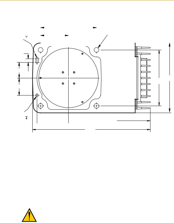
The Adept Cobra i600 and i800 robots are designed to be mounted on a smooth, flat, level surface. The mounting structure must be rigid enough to prevent vibration and flexing during robot operation. Adept recommends a 25 mm (1 in.) thick steel plate mounted to a rigid steel tube frame. Excessive vibration or mounting flexure will degrade robot performance. Figure 2-2 shows the mounting hole pattern for the Adept Cobra i-series robots.
NOTE: On the underside of the base there is a hole and a slot that can be used as locating points for user-installed dowel pins in the mounting surface; see Figure 2-2. Using locating pins can improve the ability to remove and reinstall the robot in the same position.
Adept Cobra i600/i800 Robot User’s Guide, Rev G |
19 |
Robot Installation
|
+0.015 |
|
|
|
|
|
|
|
|
|
|
|
|
|
160 |
|
|
|
|
|
|
|
|
4X Ø 14 |
|
|
|
|
|
|
|
|
|
|
|
|
|
|
|
|
|
|
|
|
|
|
|
|
|
|
|
||||
|
|
|
|
|
|
|
|
|
|
|
|
|
|
|
|
|
|
|
|
|
|
|
|
|
|
||
2x R4 |
|
|
6 |
|
|
|
|
|
|
|
|
80 |
|
|
|
|
|
|
|
|
|
|
|
THRU |
|
Units in mm |
|
|
|
|
|
|
|
|
|
|
|
|
|
|
|
|
|
|
|
|
|
|
|
||||||
0 |
|
|
|
|
|
|
|
|
|
|
|
|
|
|
|
|
|
|
|
|
|||||||
|
|
|
|
|
|
|
|
|
|
|
|
|
|
|
|
|
|
|
|
|
|
|
|
|
|
|
|
|
|
|
|
|
|
|
|
|
|
|
|
|
|
|
|
|
|
|
|
|
|
|
|
|
|
|
|
|
|
|
|
|
|
|
|
|
|
|
|
|
|
|
|
|
|
|
|
|
|
|
|
|
|
|
|
|
|
|
|
|
|
|
|
|
|
|
|
|
|
|
|
|
|
|
|
|
|
|
|
|
|
|
|
|
|
|
|
|
|
|
|
|
|
|
|
|
|
|
|
|
|
|
|
|
|
|
|
|
|
|
|
|
|
|
|
|
|
|
|
|
|
|
|
|
|
|
|
|
|
|
|
|
|
|
|
|
|
|
|
10
45
200
160
50
Ø 8 +0.015 6
0 90
90  234
234
338
Figure 2-2. Mounting Hole Pattern for Robot
Robot Mounting Procedure
1.Using the dimensions shown in Figure 2-2, drill and tap the mounting surface for four M12 - 1.75 x 36 mm (or 7/16 - 14 UNC x 1.50 in.) machine bolts (bolts not provided). See Table 2-2 for bolt and torque specifications.
2.While the robot is still bolted to the transportation pallet, connect the hydraulic lift to the eyebolt at the top of the inner link (see Figure 2-1 on page 17). Take up any slack, but do not lift the robot at this time.
WARNING: Do not attempt to lift the robot at any points other than the eyebolt provided. Do not attempt to extend the outer link of the robot until the robot has been secured in position. Failure to comply could result in the robot falling and causing either personnel injury or equipment damage.
3.Remove the four bolts securing the robot base to the pallet. Retain these bolts for possible later relocation of the equipment.
4.Lift the robot and position it directly over the mounting surface.
5.Slowly lower the robot while aligning the base and the tapped mounting holes in the mounting surface.
20 |
Adept Cobra i600/i800 Robot User’s Guide, Rev G |
Mounting the Robot
NOTE: The base casting of the robot is aluminum and can easily be dented if bumped against a harder surface. Verify that the robot is mounted squarely (will not rock back and forth) before tightening the mounting bolts.
6.Install the user-supplied mounting bolts and washers. Tighten the bolts to the torque specified in Table 2-2.
WARNING: The center of mass of the robot may cause the robot to fall over if the robot is not secured with the mounting bolts.
NOTE: Check the tightness of the mounting bolts one week after initial installation, and then recheck every 6 months. See Chapter 5 for periodic maintenance.
Table 2-2. Mounting Bolt Torque Specifications
Standard |
Size |
Specification |
Torque |
|
|
|
|
|
|
|
|
Metric |
M12 x P1.75 |
ISO Property Class 8.8 |
85 N·m |
|
|
|
|
SAE |
7/16-14 UNC |
SAE Grade 5 |
63 lbf·ft |
|
|
|
|
Adept Cobra i600/i800 Robot User’s Guide, Rev G |
21 |

Robot Installation
2.6Connectors on the Robot Interface Panel
|
|
200-240 VAC |
XSLV |
Ground |
SmartServo Port 1 |
||
Screw |
|||
|
|
|
SmartServo Port 2 |
24 VDC |
|
||
Input |
|
|
|
|
|
||
+24 VDC |
RS-232 |
||
Pin |
|
||
XIO XPANEL
Figure 2-3. Robot Interface Panel
24 VDC - for connecting user-supplied 24 VDC power to the robot. The mating connector is provided.
Ground Screw - for connecting cable shield from user-supplied 24 VDC cable.
200/240 VAC - for connecting 200-240 VAC, single-phase, input power to the robot. The mating connector is provided.
XSLV - not used in a Cobra i600/i800 robot system.
SmartServo 1/2 - not used in a Cobra i600/i800 robot system.
RS-232 - for connecting a user-supplied computer, running Adept ACE software. (DB-9, male).
XPANEL - for connecting the AIB XPANEL cable. The AIB XPANEL cable has connectors for the Front Panel (XFP), T2 pendant (XMCP), and user IO (XUSR). (DB26, high density, male).
XIO - for user I/O signals for peripheral devices. This connector provides 8 outputs and 12 inputs. See Section 4.6 on page 43 for connector pin allocations for inputs and outputs. That section also contains details on how to access these I/O signals via MicroV+. (DB26, high density, female). The optional XIO Termination Block connects here. This device provides a termination block for I/O connections, plus status LEDs and switches to test I/O signals.
22 |
Adept Cobra i600/i800 Robot User’s Guide, Rev G |

System Installation 3
3.1Cable and Parts List
Part |
Cable and Parts List |
Part # |
Part of: |
Notes |
|
|
|
|
|
|
|
|
|
|
|
|
|
A |
AIB XPANEL Cable - for |
04715-000 |
04081-000 |
Standard, iCobra |
|
|
connecting XUSR, Front Panel, |
|
|
|
|
|
and optional T2 pendant to the |
|
|
|
|
|
robot |
|
|
|
|
|
|
|
|
|
|
B |
XUSR Jumper Plug |
04736-000 |
04081-000 |
Standard, iCobra |
|
|
|
|
|
|
|
C |
Front Panel |
30356-10358 |
90356-10358 |
Standard, iCobra |
|
|
|
|
|
|
|
D |
Front Panel Cable |
10356-10500 |
90356-10358 |
Standard, iCobra |
|
|
|
|
|
|
|
E |
XMCP Jumper Plug |
04737-000 |
04081-000 |
Standard, iCobra |
|
|
|
|
|
|
|
F |
T1/T2 Bypass Plug |
05004-000 |
|
|
|
|
|
|
|
|
|
G |
T1/T2 Adapter Cable |
05002-000 |
04965-203/ |
T2 option - |
|
|
|
|
04965-210 |
3 m/10 m |
|
H |
T2 (optional) |
05215-103/ |
|||
|
|
||||
|
|
05215-110 |
|
|
|
|
|
|
|
|
|
J |
AC Power Cable - to supply |
|
|
User-supplied |
|
|
AC power to robot |
|
|
|
|
|
|
|
|
|
|
K |
24 VDC Power Cable - to supply |
|
|
User-supplied |
|
|
24 VDC to robot |
|
|
|
|
|
|
|
|
|
|
L |
24 VDC, 6 A Power Supply |
|
|
User-supplied |
|
|
|
|
|
|
|
|
AC Power Cable - to supply AC |
|
|
User-supplied |
|
|
power to 24 VDC Power Supply |
|
|
|
|
|
|
|
|
|
|
M |
RS-232 Null Modem Serial Cable, |
04116-001 |
90565-000 |
Standard, iCobra |
|
|
5 meter, for connecting |
|
|
|
|
|
user-supplied PC to robot |
|
|
|
|
|
|
|
|
|
Adept Cobra i600/i800 Robot User’s Guide, Rev G |
23 |

System Installation
3.2System Cable Diagram
Installation Procedure
Step |
Step Description |
Part(s) |
|
|
|
|
|
|
1 |
Connect AIB XPANEL cable to XPANEL on Interface Panel. |
A |
|
|
|
2 |
Verify XUSR jumper plug is installed on XUSR connector. |
B |
|
|
|
3 |
Connect Front Panel cable to Front Panel and XFP connector. |
C, D |
|
|
|
4 |
If no T2, install XMCP jumper or T1/T2 bypass plug. Skip to 5. |
E, F |
|
|
|
4a |
If you have T2, connect T1/T2 adapter cable to XMCP connector. |
G, H |
|
|
|
5 |
Connect user-supplied ground. See Section 3.8 on page 34 for locations. |
- |
|
|
|
6 |
Connect 200-240 VAC to AC Input on Interface Panel, secure with clamp. |
J |
|
|
|
7 |
Connect 24 VDC to DC Input on Interface Panel. (May need AC cable.) |
K, L |
|
|
|
8 |
Connect null modem serial cable to Interface Panel and serial port on PC. |
M |
|
|
|
|
XUSR for: |
|
|
|
|
|
|
|
|
|
|
|
- User E-Stop/Safety Gate |
B |
2 |
|
Adept Cobra |
|
|
|
|
||
|
- Muted Safety Gate |
|
|
i600/i800 Robot |
|
|
|
|
|||
|
- Jumper plug required |
XUSR |
|
|
|
|
|
|
|
|
|
|
when not used |
Jumper |
|
XUSR |
|
|
|
|
|
|
|
|
|
Plug |
|
|
|
|
|
|
|
||
|
|
|
|
|
|
|
|
|
|
||
|
|
|
|
|
3 |
|
|
|
|
|
|
|
|
D |
Front Panel |
XFP |
|
|
|
|
|
|
|
3 |
C |
|
|
|
|
|
|
|
|||
|
Cable |
|
|
|
|
|
|
|
|
||
|
|
|
|
|
|
|
|
|
|
||
|
Front Panel |
|
|
|
|
User-Supplied |
|
|
|
|
|
|
|
|
|
|
|
|
|
|
|
||
|
|
|
|
|
|
Ground Wire |
|
|
|
|
|
|
|
4a |
T1/T2 Adapter |
4a |
|
|
|
1 |
|
||
|
H |
|
|
Cable |
XMCP |
|
GND |
XSLV |
2 |
|
|
|
|
|
|
G |
A |
5 |
+24V |
|
|
|
|
|
|
|
|
DC INPUT |
|
|
|
||||
|
|
4 |
|
|
|
(24 VDC) |
XIO |
XPANEL |
RS-232 |
||
|
|
F |
|
E |
4 |
|
|
|
|
|
|
T1/T2 Bypass Plug |
XMCP Jumper Plug |
T2 Pendant (optional) |
|
Either T1/T2 Bypass Plug or XMCP Jumper Plug must be installed if T2 is not used
AIB |
Robot Interface |
XPANEL |
Panel |
Cable |
1 |
|
85 - 264 VAC |
L |
K |
|
|
Universal |
|
|||
Input |
24 VDC, 6 A |
DC Power 7 |
||
|
Cable |
|
||
8 |
Power Supply |
|
|
|
|
AC Power |
6 |
||
200-240 VAC |
J |
Cable |
||
|
||||
10 A |
|
|
||
User-Supplied PC |
single-phase |
|
running Adept ACE |
||
RS-232 Null Modem Cable |
||
|
||
|
for Robot to PC Connection |
|
|
M |
|
|
1 |
GND |
XSLV |
2 |
|
|
|
|
|
SmartServo |
+24V DC INPUT (24 VDC)
AC INPUT |
|
(200-240 VAC 1&) XIO |
XPANEL RS-232 |
8
Figure 3-1. iCobra System Cable Diagram
24 |
Adept Cobra i600/i800 Robot User’s Guide, Rev G |

Cable Connections to the Robot
3.3Cable Connections to the Robot
Installing AIB XPANEL Cable
1.Locate the AIB XPANEL cable. It is shipped in the Accessory Kit.
2.Plug the single end of the AIB XPANEL cable into the XPANEL connector on the robot interface panel. See Figure 3-1 on page 24. The AIB XPANEL cable has these connectors on the opposite ends: XUSR, XFP, and XMCP.
NOTE: The plastic molding on each connector is labeled for identification.
Installing Peripherals and Options
See Figure 3-1 on page 24 when installing these items.
1.Verify that the XUSR jumper plug is installed on the XUSR connector, or that user-supplied E-Stop devices are installed. See Section 4.7 on page 49 for information on connecting user-supplied E-Stop devices and safety circuits to the XUSR connector.
2.Connect the Front Panel cable to the XFP connector on the AIB XPANEL cable.
3.Connect the other end of the Front Panel cable to the Front Panel.
4.If you are not using the optional T2 pendant, verify that:
•The XMCP Jumper Plug is installed in the XMCP connector of the AIB XPANEL cable
or
•The T1/T2 Bypass Plug is plugged into the S1 end of the T1/T2 Adapter Cable, and the Adapter Cable is plugged into the AIB XPANEL cable.
5.If your system uses the optional T2 pendant, follow these steps.
a.Remove the XMCP jumper plug from the XMCP connector on the AIB XPANEL cable.
b.Plug the T1/T2 Adapter Cable into the XMCP connector of the AIB XPANEL cable.
c.Connect the T1/T2 Adapter Cable to the matching connector on the T2.
3.4Connecting User-Supplied PC to Robot
The Adept Cobra i600/i800 robots must be connected to a user-supplied PC for setup, control, and programming. The user loads the Adept ACE software onto the PC and connects it to the robot via an RS-232 serial cable.
Adept Cobra i600/i800 Robot User’s Guide, Rev G |
25 |

System Installation
PC Requirements
To run and use Adept ACE software, the following hardware and software are required.
NOTE: The specifications are also listed in the ACE PackXpert Datasheet, available on the Adept corporate web site.
Hardware
•Processor: Core2Duo 2.0 GHz or better
•Disk Space: 500 MB recommended minimum
•RAM: 2 GB or more
•Monitor: SVGA, minimum resolution 800 x 600
•Ethernet: (if using vision) IEEE 1394 or Gigabit-Ethernet support
Adept recommends using the Adept SmartVision™ EX vision processor
•Serial cable: A standard, null modem, shielded, RS-232 data transfer serial cable, DB-9 female connectors on both ends (supplied by Adept)
Software
•Operating System: Microsoft Vista (32-bit), Microsoft Windows® XP with Service Pack 2, Microsoft Windows® Server™ 2003 with Service Pack 1, or Microsoft Windows® 2000 with Service Pack 4
•Microsoft .NET Framework 2.0 or later (included in the installation of the Adept ACE installer)
•Microsoft Internet Explorer version 5.01 or later (necessary for viewing Online help)
Installing Serial Cable
1.Locate the RS-232 null modem serial cable that is included in the Accessory Kit.
2.Connect one end of the serial cable to the RS-232 connector on the robot interface panel. See Figure 3-1 on page 24.
3.Connect the other end of the cable to a serial port on the PC. Serial ports are also referred to as COM ports.
3.5Installing Adept ACE Software
You install Adept ACE from the Adept Software CD-ROM. Adept ACE needs Microsoft
.NET Framework. The Adept ACE Setup Wizard scans your PC for .NET, and installs it automatically if it is not already installed.
1.Insert the CD-ROM into the CD-ROM drive of your PC. If Autoplay is enabled, the Adept Software CD-ROM menu is displayed - see Figure 3-2. If Autoplay is disabled, you will need to manually start the CD-ROM.
NOTE: The online document that describes the installation process opens in the background when you select one of software installation steps below.
26 |
Adept Cobra i600/i800 Robot User’s Guide, Rev G |

Installing Adept ACE Software
2. From the Adept Software CD-ROM menu, click Install the Adept ACE Software.
Figure 3-2. Adept ACE CD-ROM Startup Menu
3.The Adept ACE Setup wizard opens - see Figure 3-4 and Figure 3-5. Follow the instructions as you step through the installation process.
Figure 3-3. Setup Welcome Screen
Figure 3-4. Ready-to-Install Screen |
|
Adept Cobra i600/i800 Robot User’s Guide, Rev G |
27 |

System Installation
Figure 3-5. Install Screen
4. When the install is complete, click Finish.
Figure 3-6. Installation Completed
5.After closing the Adept ACE Setup wizard, click Exit on the CD-ROM menu and proceed to the Start-up Procedure.
NOTE: You will have to restart the PC after installing Adept ACE.
28 |
Adept Cobra i600/i800 Robot User’s Guide, Rev G |

Connecting 24 VDC Power to Robot
3.6Connecting 24 VDC Power to Robot
Specifications for 24 VDC Power
Table 3-1. Specifications for 24 VDC User-Supplied Power Supply
Customer-Supplied Power Supply |
24 VDC (± 10%), 150 W (6 A) |
|
(21.6 V< Vin < 26.4 V) |
Circuit Protectiona |
Output must be less than 300 W peak |
|
or |
|
8 Amp in-line fuse |
|
|
Power Cabling |
1.5 – 1.85 mm² (16-14 AWG) |
|
|
Shield Termination |
Braided shield connects to ground |
|
terminal at both ends of cable. See Figure |
|
3-7 on page 31 and Figure 2-3 on page |
|
22. |
|
|
aUser-supplied 24 V power supply must incorporate overload protection to limit peak power to less than 300 W, or 8 A in-line fuse protection must be added to the 24 V power source. (In case of multiple robots on a common 24 V supply, each robot must be fused individually.)
NOTE: Fuse information is located on the AIB electronics
The power requirements for the user-supplied power supply will vary depending on the configuration of the robot and connected devices. Adept recommends a 24 V, 6 A power supply to allow for startup current draw and load from connected user devices, such as solenoids and digital I/O loads. If multiple robots are to be sourced from a common 24 V power supply, increase the supply capacity by 3 A for each additional robot.
CAUTION: Make sure you select a 24 VDC power supply that meets the specifications in Table 3-1. Using an under-rated supply can cause system problems and prevent your equipment from operating correctly. See Table 3-2 for recommended power supplies.
Table 3-2. Recommended 24 VDC Power Supplies
Vendor Name |
Model |
Ratings |
|
|
|
|
|
|
XP Power |
JMP160PS24 |
24 VDC, 6.7 A, 160 W |
|
|
|
AstroDyne |
SP-150-24 |
24 VDC, 6.3 A, 150 W |
|
|
|
Mean Well |
SP-150-24 |
24 VDC, 6.3 A, 150 W |
|
|
|
Adept Cobra i600/i800 Robot User’s Guide, Rev G |
29 |

System Installation
Connecting 24 VDC
This section covers the cable that connects the 24 VDC power supply to the robot.
24 VDC Mating Connector
The 24 VDC mating connector and two pins are supplied with each system. They are shipped in the Accessory Kit.
Table 3-3. 24 VDC Mating Connector Specs |
||
|
|
|
Connector Details |
Connector receptacle, 2 position, type: |
|
|
Molex Sabre, 18 A, 2-Pin |
|
Ground |
|
|
Molex P/N 44441-2002 |
||
|
||
|
|
|
|
Digi-Key P/N WM18463-ND |
|
24 VDC |
|
|
Adept P/N 02708-000 |
||
|
||
|
|
|
|
|
|
Pin Details |
Molex connector crimp terminal, |
|
|
female, 14-18 AWG |
|
|
|
|
|
Molex P/N 43375-0001 |
|
|
|
|
|
Digi-Key P/N WM18493-ND |
|
|
|
|
|
Adept P/N 02709-000 |
|
|
|
|
Recommended crimping tool: Molex Hand |
Molex P/N 63811-0400 |
|
Crimper |
|
|
Digi-Key P/N WM9907-ND |
||
|
||
|
|
|
Creating 24 VDC Cable
1.Locate the connector and pins from the preceding table.
2.Use 14-16 AWG wire to create the 24 VDC cable. Select the wire length to safely reach from the user-supplied 24 VDC power supply to the robot base.
3.Crimp the pins onto the wires using the crimping tool recommended in the preceding table.
4.Insert the pins into the connector. Confirm that the 24 V and ground wires are in the correct terminals in the plug.
5.Prepare the opposite end of the cable for connection to your user-supplied 24 VDC power supply.
Installing 24 VDC Robot Cable
1.Connect one end of the shielded 24 VDC cable to your user-supplied 24 VDC power supply. See Figure 3-7. The cable shield should be connected to frame ground on the power supply. Do not turn on the 24 VDC power until instructed to do so in Chapter 4.
2.Plug the mating connector end of the 24 VDC cable into the 24 VDC connector on the interface panel on the back of the robot. The cable shield should be connected to the ground point on the interface panel.
30 |
Adept Cobra i600/i800 Robot User’s Guide, Rev G |
Loading...