

Page 1
Adept Quattro
User’s Guide
covers the Adept Quattro s650H, s650HS,
s800H, and s800HS Robots
Page 2

Page 3
Adept Quattro
User’s Guide
covers the Adept Quattro s650H, s650HS,
s800H, and s800HS Robots
P/N: 09955-000, Rev F
May, 2013
5960 Inglewood Drive • Pleasanton, CA 94588 • USA • Phone 925.245.3400 • Fax 925.960.0452
Otto-Hahn-Strasse 23 • 44227 Dortmund • Germany • Phone +49.231.75.89.40 • Fax +49.231.75.89.450
Block 5000 Ang Mo Kio Avenue 5 • #05-12 Techplace II • Singapore 569870 • Phone +65.6755 2258 • Fax +65.6755 0598
Page 4

Copyright Notice
The information contained herein is the property of Adept Technology, Inc., and shall not be reproduced
in whole or in part without prior written approval of Adept Technology, Inc. The information herein is
subject to change without notice and should not be construed as a commitment by Adept Technology,
Inc. The documentation is periodically reviewed and revised.
Adept Technology, Inc., assumes no responsibility for any errors or omissions in the documentation.
Critical evaluation of the documentation by the user is welcomed. Your comments assist us in
preparation of future documentation. Please submit your comments to: techpubs@adept.com.
Copyright 2010-2013 by Adept Technology, Inc. All rights reserved.
Adept, the Adept logo, the Adept Technology logo, AdeptVision, AIM, Blox, Bloxview, FireBlox, Fireview,
Meta Controls, MetaControls, Metawire, Soft Machines, and Visual Machines are registered trademarks
of Adept Technology, Inc.
Brain on Board is a registered trademark of Adept Technology, Inc. in Germany.
Adept ACE, Adept Quattro s650H, Adept Quattro s650HS, Adept Quattro s800H, Adept Quattro s800HS,
Adept SmartController CX, Adept SmartController EX, Adept T2, Adept T20, AIB, eAIB, eV+, and V+ are
trademarks of Adept Technology, Inc.
Any trademarks from other companies used in this publication
are the property of those respective companies.
Created in the United States of America
Page 5

Table of Contents
Chapter 1: Introduction 11
1.1 Adept Quattro™ Robots, Product Description
Major Differences between Quattro H and HS Robots 11
Adept AIB™, eAIB™ 14
Quattro Robot Base 14
Inner Arms 15
Ball Joints, Outer Arms 16
Platforms 17
Adept SmartController™ 20
1.2 Warnings, Cautions, and Notes in Manual
1.3 Safety Precautions
1.4 What to Do in an Emergency
1.5 Additional Safety Information
1.6 Intended Use of the Robots
1.7 Installation Overview
1.8 Manufacturer’s Declaration
1.9 How Can I Get Help?
Related Manuals 25
Adept Document Library 25
11
21
22
22
22
23
23
24
25
Chapter 2: Robot Installation - H 27
2.1 Transport and Storage
2.2 Unpacking and Inspecting the Adept Equipment
Unpacking 27
2.3 Repacking for Relocation
2.4 Environmental and Facility Requirements
2.5 Mounting Frame
Frame Orientation 31
Frame Construction 31
Robot-to-Frame Considerations 31
Mounting 31
Gussets 32
2.6 Mounting the Robot Base
Robot Orientation 32
Mounting Surfaces 32
Mounting Options 33
Mounting Procedure from Above the Frame 33
Adept Quattro User's Guide, Rev F
Page 5 of 196
27
27
29
29
29
32
Page 6

Mounting Procedure from Below the Frame 34
Install Mounting Hardware 35
2.7 Attaching the Outer Arms and Platform
Clocking the Platform to the Base 37
Attaching the Outer Arms 39
37
Chapter 3: Robot Installation - HS 43
3.1 Transport and Storage
3.2 Unpacking and Inspecting the Adept Equipment
Before Unpacking 43
Upon Unpacking 43
Unpacking 43
3.3 Repacking for Relocation
3.4 Environmental and Facility Requirements
3.5 Mounting Frame
Frame Mounting Tabs 47
Robot-to-Frame Considerations 47
Mounting 47
Gussets 48
3.6 Cable Inlet Box
Assembling Cable Inlet Box 48
Connecting the Cables 53
Installing the Cable Inlet Box 53
3.7 Mounting the Robot Base
Robot Orientation 55
Mounting Surfaces 55
Mounting Options 55
Mounting Procedure from Above the Frame 56
Mounting Procedure from Below the Frame 57
Install Mounting Hardware 58
3.8 Attaching the Outer Arms and Platform
Clocking the Platform to the Base 60
Attaching the Outer Arms 61
3.9 Attaching the Cable Tray
43
43
45
46
46
48
55
59
64
Chapter 4: System Installation 71
4.1 System Cable Diagram
4.2 Cable Parts List
4.3 Installing the SmartController Motion Controller
4.4 Connecting User-Supplied PC to Robot
PC Requirements 73
Adept Quattro User's Guide, Rev F
Page 6 of 196
71
72
72
72
Page 7

4.5 Installing Adept ACE Software
4.6 Description of Connectors on Robot Interface Panel
4.7 Cable Connections from Robot to SmartController
4.8 Connecting 24 VDC Power to Robot
Specifications for 24 VDC Robot and Controller Power 76
Details for 24 VDC Mating Connector 77
Procedure for Creating 24 VDC Cable 77
Installing 24 VDC Robot Cable 78
4.9 Connecting 200-240 VAC Power to Robot
Specifications for AC Power 79
Details for AC Mating Connector 81
Procedure for Creating 200-240 VAC Cable 81
Installing AC Power Cable to Robot 82
4.10 Grounding the Adept Quattro Robot System
Adept Quattro Robot Base 82
Quattro HS Robot Base 83
Robot-Mounted Equipment 83
4.11 Installing User-Supplied Safety Equipment
73
74
75
76
79
82
84
Chapter 5: System Operation 85
5.1 Robot Status Display Panel
5.2 Status Panel Fault Codes
5.3 Using the Brake-Release Button
Brakes 86
Brake-Release Button 87
5.4 Front Panel
5.5 Connecting Digital I/O to the System
5.6 Using Digital I/O on Robot XIO Connector
Optional I/O Products 91
XIO Input Signals 91
XIO Output Signals 92
XIO Breakout Cable 94
5.7 Starting the System for the First Time
Verifying Installation 96
Turning on Power and Starting Adept ACE 97
Enabling High Power 98
Verifying E-Stop Functions 98
Verify Robot Motions 98
5.8 Quattro Motions
Straight-line Motion 99
Containment Obstacles 99
Tool Flange Rotation Extremes 99
85
86
86
87
88
89
96
99
Adept Quattro User's Guide, Rev F
Page 7 of 196
Page 8

5.9 Learning to Program the Adept Quattro Robot
103
Chapter 6: Optional Equipment Installation 105
6.1 End-Effectors
Attaching 105
Aligning 105
Grounding 105
Accessing Vacuum 105
6.2 Routing End-effector Lines
6.3 Ball Stud Locks
Installing a Ball Stud Lock 108
Removing a Ball Stud Lock 109
105
105
107
Chapter 7: Technical Specifications 111
7.1 Dimension Drawings
7.2 Adept Quattro Internal Connections
7.3 XSYS/XSYSTEM Connector
7.4 XSLV Connector
7.5 Robot Specifications
7.6 Payload Specifications
Torque and Rotation Limits 122
Payload Mass vs. Acceleration 123
Payload Inertia vs. Acceleration 124
7.7 Robot Mounting Frame, Quattro s650H Robot
111
119
119
120
120
122
124
Chapter 8: Maintenance - H 131
8.1 Periodic Maintenance Schedule
8.2 Checking Safety Systems
8.3 Checking Robot Mounting Bolts
8.4 Checking Robot Gear Drives
8.5 Checking Fan Operation
8.6 Replacing the AIB or eAIB Chassis
Removing the AIB/eAIB Chassis 135
Installing a New AIB/eAIB Chassis 138
8.7 Commissioning a System with an eAIB
Safety Commissioning Utilities 140
E-Stop Configuration Utility 142
E-Stop Verification Utility 142
Teach Restrict Configuration Utility 143
Teach Restrict Verification Utility 143
Adept Quattro User's Guide, Rev F
Page 8 of 196
131
134
134
134
135
135
139
Page 9

8.8 Replacing the Encoder Battery Pack
Battery Replacement Interval 145
Battery Replacement Procedure 145
8.9 Replacing a Platform
Replacement 147
Configuration 148
8.10 Replacing a Ball Joint Insert
8.11 Replacing Outer Arm Spring Assemblies
Removing Outer Arm Spring Assemblies 149
Installing Outer Arm Spring Assemblies 150
144
147
149
149
Chapter 9: Maintenance - HS 153
9.1 Cleaning
Water Shedding 153
Wash-Down 153
Chemical Compatibility 154
9.2 Periodic Maintenance
9.3 Checking Safety Systems
9.4 Checking Robot Mounting Bolts
9.5 Checking Robot Gear Drives
9.6 Checking Fan Operation
9.7 Removing and Installing the Cable Inlet Box
Removing the Cable Inlet Box 160
Installing the Cable Inlet Box 161
9.8 Replacing the AIB/eAIB Chassis
Removing the AIB/eAIB Chassis 162
Installing a New AIB/eAIBChassis 165
9.9 Commissioning a System with an eAIB
Safety Commissioning Utilities 166
E-Stop Configuration Utility 168
E-Stop Verification Utility 168
Teach Restrict Configuration Utility 169
Teach Restrict Verification Utility 169
9.10 Replacing the Encoder Battery Pack
Battery Replacement Interval 171
Battery Replacement Procedure 171
9.11 Replacing a Platform
Replacement 174
Configuration 175
153
154
158
158
158
159
160
161
166
171
174
Adept Quattro User's Guide, Rev F
Page 9 of 196
Page 10

9.12 Replacing a Ball Joint Insert
9.13 Replacing Outer Arm Spring Assemblies
Removing Outer Arm Spring Assemblies 176
Installing Outer Arm Spring Assemblies 178
175
176
Chapter 10: Robot Cleaning/ Environmental Concerns- H 181
10.1 Ambient Environment
Humidity 181
Temperature 182
10.2 Cleaning
Caustic Compatibility 182
Water Shedding 182
Wipe-Down 182
10.3 Cleanroom Classification
10.4 Design Factors
Robot Base and Components 183
Inner Arms 183
Ball Joints 183
Outer Arms 183
Springs 183
Platforms 184
10.5 Installing Cable Seal Kit
Overview 184
Installation Procedure 185
181
182
182
182
184
Chapter 11: Environmental Concerns - HS 191
11.1 Ambient Environment
Humidity 191
Temperature 192
11.2 Cleanroom Classification
11.3 Design Factors
Robot Base and Components 192
Inner Arms 192
Ball Joints 192
Outer Arms 193
Spring Assemblies 193
Platforms 193
Adept Quattro User's Guide, Rev F
Page 10 of 196
191
192
192
Page 11

Chapter 1: Introduction
1.1 Adept Quattro™ Robots, Product Description
The Adept Quattro robot is a four-axis parallel robot. The four identical axis motors control
movement of the robot tool in X, Y, and Z directions, as well as Theta rotation.
The Adept Quattro robot requires an Adept SmartController™ motion controller for operation.
The robot is user-programmed and controlled using the SmartController motion controller. The
robot servo code runs on an Adept SmartServo distributed-motion control platform embedded
in the robot base as part of the power amplifiers.
There are two sizes of Adept Quattro robots, each available with anodized and electroless
nickel (EN) aluminum platforms and outer arm spoons:
l
Adept Quattro s650H (Standard) and Adept Quattro s650HS (EN)
and
l
Adept Quattro s800H (Standard) and Adept Quattro s800HS (EN)
The Adept Quattro s650H and s650HS arealso available with stainless steel (SS)
platforms and outer arm spoons. The inner arm ends, AIB/eAIB, and cable box
are electroless nickel.
The electroless nickel and stainless steel versions of the Quattro s650HS robot are USDA
Accepted.
In most aspects, the robots are similar enough that they will be covered together. In areas
where there are significant differences, the Quattro H and Quattro HS robots will be presented
in two chapters, using titles such as Robot Installation - H for the s650H and s800H robots,
and Robot Installation—HS for the s650HS and s800HS robots.
Major Differences between Quattro H and HS Robots
Note that any of the available aluminum platforms can be used on the Quattro s650H and
s800H robots.
The Quattro s650HS and s800HS have electroless nickel plating on all aluminum parts. The
s650HS is also available with stainless steel in place of aluminum for platforms and outer arm
ends.
Table 1-1. Quattro H/HS Differences
USDA Accepted
Standard
(s650H/s800H)
No s650HS - Yes/s800HS - No
HS (s650HS/s800HS)
(Meat and Poultry)
IP- rating IP-65, Option IP-66, Standard
P30 Platform, no Hard-anodized, EN, or Electroless Nickel (EN) or Stainless
Adept Quattro User's Guide, Rev F
Page 11 of 196
Page 12

Chapter 1: Introduction
Standard
(s650H/s800H)
HS (s650HS/s800HS)
rotation SS Steel (SS on s650HS only)
P31 Platform, 46.25° Hard-anodized, EN, orSSEN or SS (SS on s650HS only)
P32 Platform, 92.5° Hard-anodized, EN, orSSEN or SS (SS on s650HS only)
P34 Platform, 185° Hard-anodized, EN, orSSEN or SS (SS on s650HS only)
Inner Arm Hubs and
Hard-Anodized Electroless Nickel
Ends
Outer Arm Spoons Hard-Anodized EN or SS (SS on s650HS only)
Base Mounting Pad
M16-2.0, through-hole M16-2.0, blind, 40 mm bolt
Holes
Base Coating material White polyurethane
White ETFE (Teflon), USDA approved
powder
Adept AIB/eAIB Black Anodized, Single-
EN, 6-bolt installation
bolt installation
Cable Inlet box Hard-Anodized, Option EN, Standard
Cable tray Not required Required (for USDA)
Status Display Half-height Full-height, to shield labels
Protective Earth Ground On base-mounting pad In cable inlet box
Motor covers White with blue Adept
Solid white, no label
label
Exposed bolts and
No Yes
screws all gasketed
Similarities Between the Quattro Robots
l
All models use the same motors
l
All models share the same base casting, although the H and HS have some machining
and coating differences.
l
The mounting hole pattern for the bases is the same.
l
All share the same inner arm design. Platform coatings/materials differ for HS robots,
but dimensions do not.
l
All can have either an AIB or an eAIB.
Adept Quattro User's Guide, Rev F
Page 12 of 196
Page 13
Chapter 1: Introduction
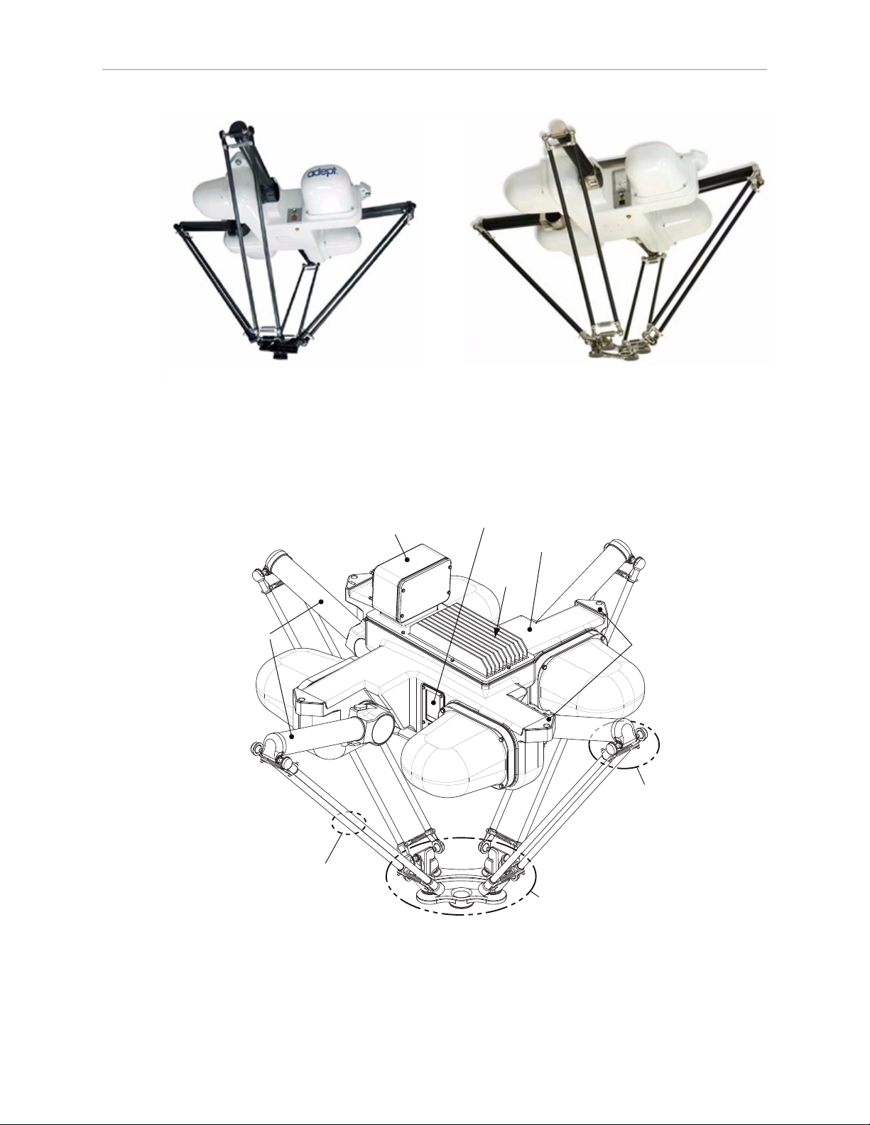
Outer
A
rms
Platform
(P31 shown)
Cable Inlet Box
Inner
Arms
Motor
Cover
AIB
Mounting
Pads
Base
Ball Joints
and Spring
Assemblies
Status Display
Panel
Figure 1-1. Adept Quattro Robots (s650H, s650HS shown)
Note the difference between the Status Display Panels, as shown in these two photos.
Figure 1-2. Major Robot Components, Isometric View (s650HS shown)
Adept Quattro User's Guide, Rev F
Page 13 of 196
Page 14

Chapter 1: Introduction
Adept AIB™, eAIB™
The power amplifiers for the Adept Quattro robot are embedded in the base of the robot. This
amplifier section is known as the Amplifiers in Base (AIB or eAIB)distributed motion control
platform, and provides closed-loop servo control of the robot amplifiers, as well as robot I/O.
There are two versions offered: the AIB and the eAIB. Both provide the power amplifiers and
full servo control. Both are available in either anodized or electroless nickel finishes.
The Adept AIB and eAIB feature:
l
On-board digital I/O: 12 inputs, 8 outputs
l
Low EMI for use with noise-sensitive equipment
l
No external fan for quiet operation
l
8 kHz servo rate to deliver low positional errors and superior path following
l
Sine-wave commutation to lower cogging torque and improve path following
l
Digital feed-forward design to maximize efficiency, torque, and velocity
l
Temperature sensors on all amplifiers and motors for maximum reliability and easy
troubleshooting
Adept eAIB only:
l
Hardware-based E-Stop and Teach Restrict controls
These are for improved safety relative to European standards implemented in 2012.
The two anodized amplifiers (H) look very similar, and are interchangeable.
The two electroless nickel amplifiers (HS)look very similar, and are interchangeable.
NOTE:The H and HSamplifiers and their cable inlet boxes are not
interchangeable.
Quattro Robot Base
The Adept Quattro robot base is an aluminum casting that houses the four drive motors, and
supports the power amplifiers. It provides four mounting pads for attaching the base to a rigid
support frame. The Status Display Panel is mounted on the side of the robot base.
Adept Quattro User's Guide, Rev F
Page 14 of 196
Page 15
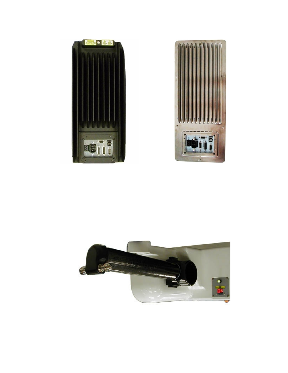
Chapter 1: Introduction
Figure 1-3. Adept AIBs (Quattro H AIB on left)
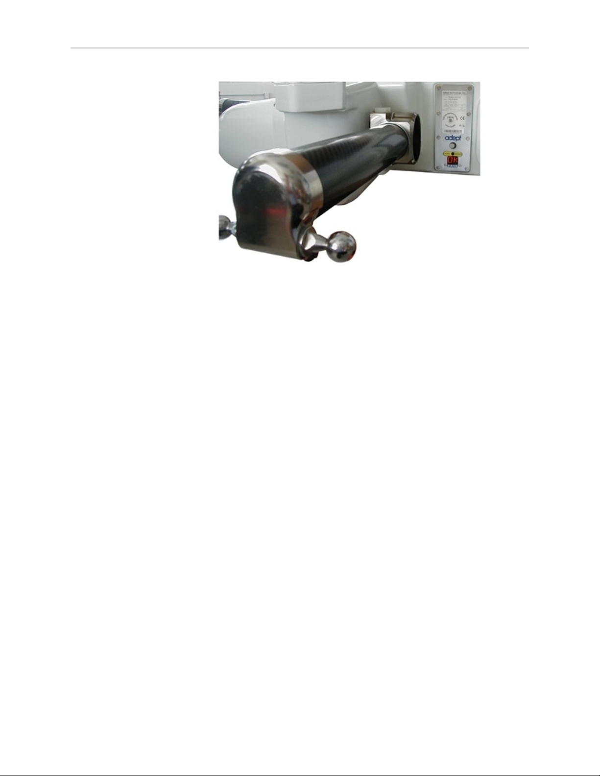
Inner Arms
The four robot motors attach directly to the inner arms through a high-performance gear
reducer. Other than optional, user-supplied hardware mounted on the platform, these are the
only drive motors in the Quattro robot. The following figures show the precision carbon fiber
assembly of the inner arms on a Quattro H robot and Quattro HS robot. The ends of the inner
arms on the Quattro HS robots are plated with electroless nickel, rather than hard-anodized.
The RIA-compliant hard stops limit the inner arm motion to -52° and +124°.
Figure 1-4. Quattro H Robot Inner Arm, Status Panel
Adept Quattro User's Guide, Rev F
Page 15 of 196
Page 16
Chapter 1: Introduction
Figure 1-5. Quattro HS Robot Inner Arm, Status Panel
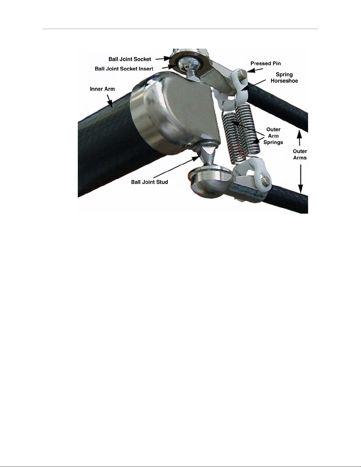
Ball Joints, Outer Arms
The inner arm motion is transmitted to the platform through the outer arms, which are
connected between the inner arms and platform with precision ball joints. The outer arms are
carbon fiber epoxied assemblies with identical ball joint sockets at each end. A bearing insert
in each socket accepts the ball joint studs on the inner arms and platform, and allows for
approximately ± 60° of relative motion. No ball joint lubrication is required.
Adept Quattro User's Guide, Rev F
Page 16 of 196
Page 17
Chapter 1: Introduction
Figure 1-6. Quattro Ball Joint Assembly, Quattro HS Robot shown
Each pair of outer arms is held together with spring assemblies that pre-tension the ball joints.
The outer arms can be installed and removed without tools.
Platforms
The platform converts the motion of the four Quattro motors into Cartesian motion and, for all
but the fixed platform, Theta rotation of the robot tool.
The Adept Quattro robot currently supports four models of platforms, depending on the
amount of Theta rotation and inertia needed.
NOTE:The four models of platforms require different robot parameters.
The suffix on the part numbers that follow indicates the finish or material of the platform.
Refer to Materials and Finishes on page 19.
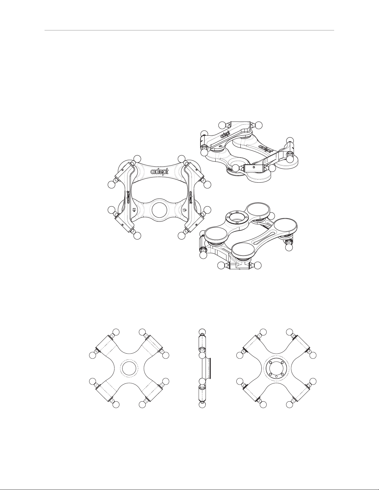
P31 Platform (P/N 09503-xxx)
The P31 platform has a rotation range of ±46.25°. The tool flange is machined into one of the
pivot links. It does not rotate in relation to the pivot link, so there are no gears or belts
involved. See Figure 1-7.
P30 Platform (P/N 09730-xxx)
The P30 platform is a fixed platform that provides no Theta rotation. The tool flange is
machined into the one-piece platform. See Figure 1-8.
Adept Quattro User's Guide, Rev F
Page 17 of 196
Page 18
Chapter 1: Introduction
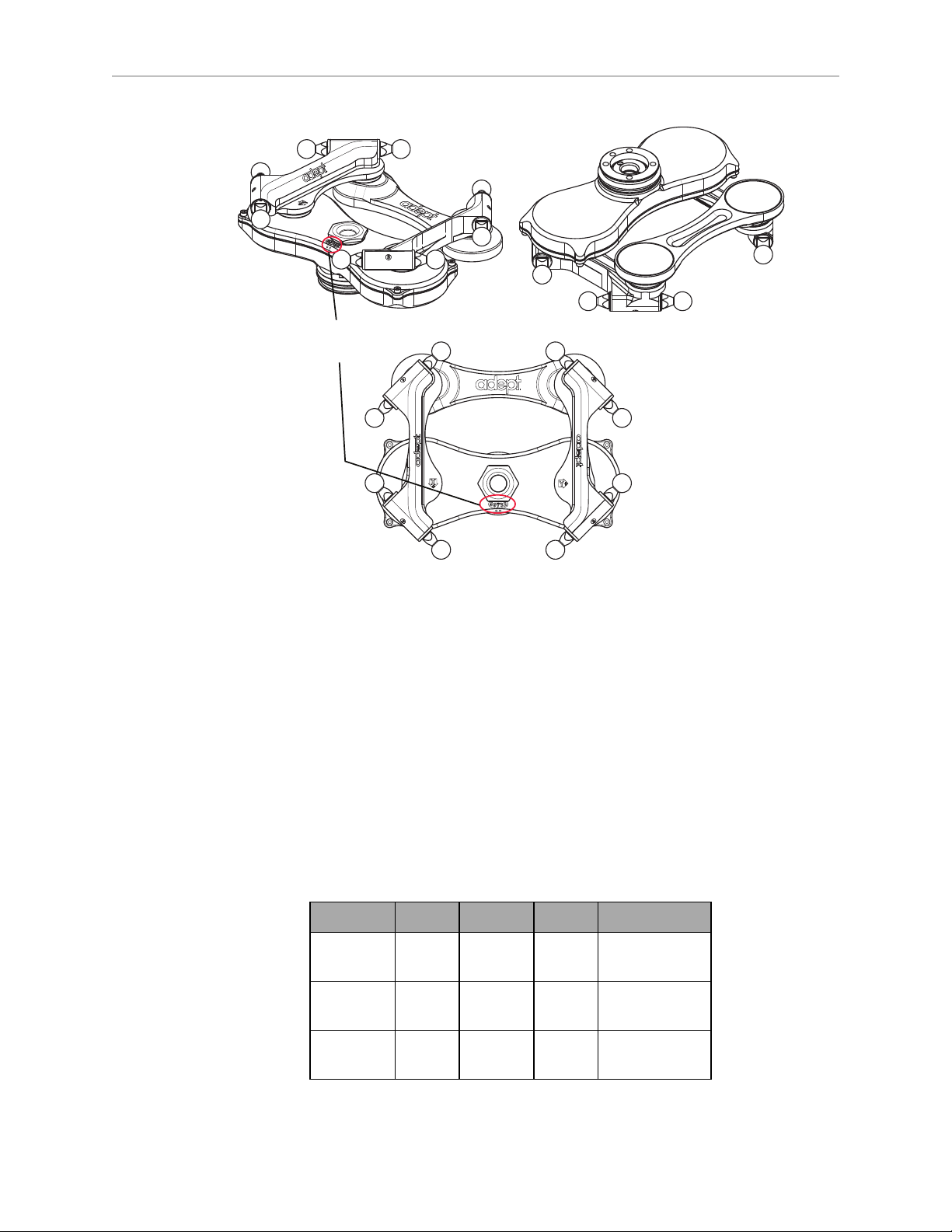
P32 Platform (P/N 09732-xxx)
The P32 platform has a rotation range of ±92.5°. The tool flange is mounted on one of the pivot
links. See Figure 1-9.
P34 Platform (P/N 09734-xxx)
The P34 platform has a rotation range of ±185°. The tool flange is mounted on one of the pivot
links. See Figure 1-9.
Figure 1-7. P31 Platform, Hard-Anodized Version
NOTE:Adept logo, joint numbers, and axes will not be etched on the electroless
nickel platforms.
Figure 1-8. P30 Platform, Electroless Nickel and Stainless Steel Versions
Adept Quattro User's Guide, Rev F
Page 18 of 196
Page 19
Chapter 1: Introduction
Model Number
& Two Dots
Figure 1-9. P32 Platform, Hard-Anodized Version
NOTE:The only visible difference between the P32 and P34 platforms is the model
number, and the two or four dots immediately below that number. Two dots
designate a P32 platform.
Materials and Finishes
Platforms are available in:
l
Aluminum with hard-anodized finish
l
Aluminum with electroless nickel finish
l
Stainless steel
The following table shows which materials and finishes are compatible with which robots:
s650H s650HS s800H Part Number
Hard
Yes No Yes XXXXX-000
Anodized
Electroless
Yes Yes Yes XXXXX-100
Nickel
Stainless
Yes Yes No XXXXX-200
Steel
Adept Quattro User's Guide, Rev F
Page 19 of 196
Page 20

Chapter 1: Introduction
Platform Clocking
Rotational platforms are constructed such that the clocking, or rotational alignment, of the
platform relative to the robot base is critical. This is detailed in Clocking the Platform to the
Base on page 37.
Platform Shipping
l
The platform and outer arms are removed.
l
The platform is shipped pre-assembled as a unit.
You will need to connect the outer arms between the inner arms and the platform to
reassemble the robot. The outer-arm assemblies are interchangeable.
Any end-effectors and their air lines and wiring are user-supplied.
Adept SmartController™
The SmartController motion controller is the foundation of Adept’s family of highperformance, distributed motion controllers. The SmartController is designed for use with:
l
Adept Quattro robots
l
Adept Cobra™ s600/s800 robots
l
Adept Viper™ robots
l
Adept Python™ linear modules
l
Adept MotionBlox-10™ servo-controller and amplifier
l
Adept sMI6™ (SmartMotion) interface modules
The contoller supports a conveyor tracking option, as well as other options. There are two
models available: the SmartController CX, which uses the V+ operating system, and the
SmartController EX, which uses the eV+ operating system. Both models offer scalability and
support for IEEE 1394-based digital I/O and general motion expansion modules. The IEEE
1394 interface is the backbone of Adept SmartServo, Adept's distributed controls architecture
supporting Adept products. The SmartControllers also include Fast Ethernet and DeviceNet.
Adept Quattro User's Guide, Rev F
Page 20 of 196
Page 21
Chapter 1: Introduction
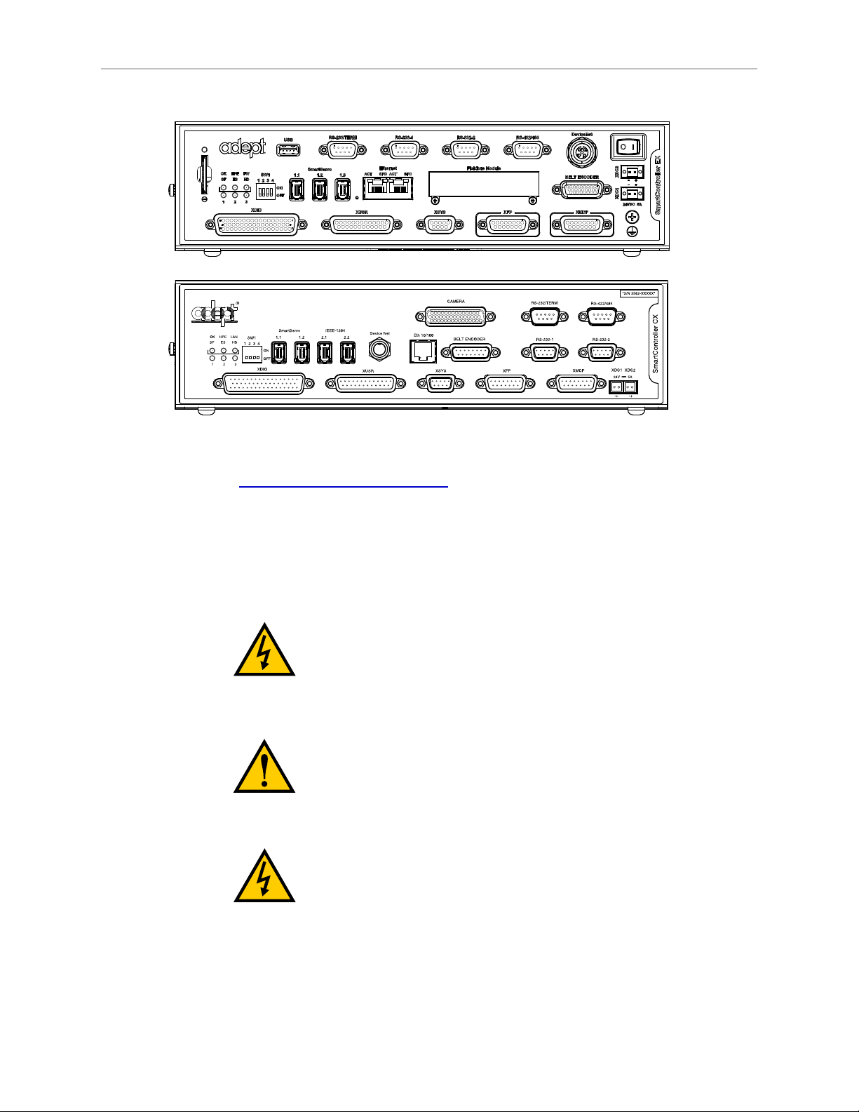
Figure 1-10. Adept SmartController EX and CX
Refer to the Adept SmartController User’s Guide for SmartController specifications.
1.2 Warnings, Cautions, and Notes in Manual
There are six levels of special alert notation used in Adept manuals. In descending order of
importance, they are:
This indicates an imminently hazardous electrical
situation which, if not avoided, will result in death or
serious injury.
This indicates an imminently hazardous situation which,
if not avoided, will result in death or serious injury.
This indicates a potentially hazardous electrical situation
which, if not avoided, could result in injury or major
damage to the equipment.
Adept Quattro User's Guide, Rev F
Page 21 of 196
Page 22
NOTE:Notes provide supplementary information, emphasize a point or procedure,
or give a tip for easier operation.
1.3 Safety Precautions
Chapter 1: Introduction
This indicates a potentially hazardous situation which, if
not avoided, could result in injury or major damage to
the equipment.
This indicates a situation which, if not avoided, could
result in damage to the equipment.
DANGER:An Adept Quattro s650/s800 robot can cause
serious injury or death, or damage to itself and other
equipment, if the following safety precautions are not
observed:
l All personnel who install, operate, teach, program, or maintain the system must read
this guide, read the Adept Robot Safety Guide, and complete a training course for their
responsibilities in regard to the robot.
l All personnel who design the robot system must read this guide, read the Adept Robot
Safety Guide, and must comply with all local and national safety regulations for the
location in which the robot is installed.
l The robot system must not be used for purposes other than described in Intended Use of
the Robots on page 23. Contact Adept if you are not sure of the suitability for your
application.
l The user is responsible for providing safety barriers around the robot to prevent anyone
from accidentally coming into contact with the robot when it is in motion.
l Power to the robot and its power supply must be locked out and tagged out before any
maintenance is performed.
1.4 What to Do in an Emergency
Press any E-Stop button (a red push-button on a yellow background/field) and then follow the
internal procedures of your company or organization for an emergency situation. If a fire
occurs, use CO2to extinguish the fire.
1.5 Additional Safety Information
Adept provides other sources for more safety information.
Adept Quattro User's Guide, Rev F
Page 22 of 196
Page 23

Chapter 1: Introduction
The Manufacturer’s Declaration of Conformity (MDOC) lists all standards with which each
robot complies. See Manufacturer’s Declaration on page 24.
The Adept Robot Safety Guide provides detailed information on safety for Adept robots. It also
gives resources for more information on relevant standards. It ships with each robot manual,
and is also available from the Adept Document Library. For details, see Adept Document
Library on page 25.
1.6 Intended Use of the Robots
The Adept Quattro s650 robot is intended for use in parts assembly and material handling for
payloads up to 6.0 kg (13.2 lb) for anodized and electroless nickel platforms, and payloads up
to 3 kg (6.6 lb) for stainless steel platforms.
The Adept Quattro s800 robot is intended for use in parts assembly and material handling for
payloads up to 4.0 kg (8.8 lb).
See Robot Specifications on page 120 for complete information on the robot specifications.
Refer to the Adept Robot Safety Guide for details on the intended use of Adept robots.
1.7 Installation Overview
The system installation process is summarized in the following table. Also, refer to System
Cable Diagram on page 71.
NOTE:For dual-robot installations, see the Adept Dual-Robot Configuration
Procedure, which is available in the Adept Document Library.
Table 1-2. Installation Overview
Task to be Performed Reference Location
Mount the cable box (Quattro HS robot or Quattro H
robot with IP-65 option).
Mount the robot to a level, stable mounting frame. Mounting the Robot Base on page
Attach the robot outer arms and platform. Attaching the Outer Arms and
Install the SmartController, Front Panel, Pendant (if
purchased), and Adept ACE software.
Install the IEEE 1394 and XSYS cables between the
robot and SmartController.
Cable Inlet Box on page 48 and
Installing Cable Seal Kit on page
184.
32.
Platform on page 37.
Installing the SmartController
Motion Controller on page 72.
Cable Connections from Robot to
SmartController on page 75.
Create a 24 VDC cable and connect it between the
SmartController and the user-supplied 24 VDC
power supply.
Create a 24 VDC cable and connect it between the
robot and the user-supplied 24 VDC power supply.
Create a 200-240 VAC cable and connect it between Connecting 200-240 VAC Power to
Adept Quattro User's Guide, Rev F
Page 23 of 196
Installing the SmartController
Motion Controller on page 72.
Connecting 24 VDC Power to Robot
on page 76.
Page 24

Chapter 1: Introduction
Task to be Performed Reference Location
the robot and the facility AC power source. Robot on page 79.
Install user-supplied safety barriers in the workcell. Installing User-Supplied Safety
Equipment on page 84.
Connect digital I/O through the robot XIO connector. Using Digital I/O on Robot XIO
Connector on page 89.
Start the system, including system start-up and
testing operation.
Install optional equipment, including end-effectors,
user air and electrical lines, external equipment, etc.
1.8 Manufacturer’s Declaration
The Manufacturer’s Declaration of Incorporation and Conformity for Adept robot systems can
be found on the Adept website, in the Download Center of the Support section.
http://www.adept.com/support/downloads/file-search
NOTE:The Download Center requires that you are logged in for access. If you are
not logged in, you will be redirected to the Adept website Login page, and then
automatically returned to the Download Center when you have completed the login
process.
1.
From the Download Types drop-down list, select Manufacturer Declarations.
2.
From the Product drop-down list, select Adept Quattro Robots category.
3.
Click Begin Search. The list of available documents is shown in the Search Results area,
which opens at the bottom of the page. You may need to scroll down to see it.
Starting the System for the First Time
on page 96.
End-Effectors on page 105.
4.
Use the Description column to locate the document for the language you want, and then
click the corresponding Download ID number to access the Download Details page.
5.
On the Download Details page, click Download to open or save the file.
Adept Quattro User's Guide, Rev F
Page 24 of 196
Page 25
1.9 How Can I Get Help?
Refer to the How to Get Help Resource Guide (Adept P/N 00961-00700) for details on getting
assistance with your Adept software and hardware. Additionally, you can access information
sources on Adept’s corporate website:
http://www.adept.com
Related Manuals
This manual covers the installation, operation, and maintenance of an Adept Quattro robot
system. There are additional manuals that cover programming the system, reconfiguring
installed components, and adding optional components. See the following table. These
manuals are available on the Adept software CD-ROM shipped with each system.
Manual Title Description
Adept Robot Safety Guide Contains safety information for Adept robots.
Chapter 1: Introduction
Table 1-3. Related Manuals
Adept SmartController User’s
Guide
Adept ACE User’s Guide Describes the installation and use of Adept ACE.
Adept Dual-Robot
Configuration Procedure
Adept T20 Pendant User's
Guide
Adept T2 Pendant User's
Guide
Contains complete information on the installation and
operation of the Adept SmartController and the optional sDIO
product.
Contains cable diagrams and configuration procedures for a
dual-robot system.
Describes the use of the optional Adept manual control
pendant.
Adept Document Library
The Adept Document Library (ADL) contains documentation for Adept products. You can
access the ADL from the Adept website. Select:
Support > Document Library
from the Adept home page. To go directly to the Adept Document Library, type the following
URL into your browser:
http://www.adept.com/Main/KE/DATA/adept_search.htm
To locate information on a specific topic, use the Document Library search engine on the ADL
main page, or select one of the available menu options. To view a list of available product
documentation, use the menu links located above the search field.
Adept Quattro User's Guide, Rev F
Page 25 of 196
Page 26

Page 27

Chapter 2: Robot Installation - H
2.1 Transport and Storage
This equipment must be shipped and stored in a temperature-controlled environment, within
the range –25 to +55° C (-13 to 131° F). The recommended humidity range is 5 to 90 percent,
non-condensing. It should be shipped and stored in the Adept-supplied crate, which is
designed to prevent damage from normal shock and vibration. You should protect the crate
from excessive shock and vibration.
Use a forklift, pallet jack, or similar device to transport and store the packaged equipment.
The robot must always be stored and shipped in an upright position in a clean, dry area that
is free from condensation. Do not lay the crate on its side or any other non-upright position.
This could damage the robot.
The Adept Quattro robot weighs 118 to 123 kg (260 to 271 lb) with no options installed.
2.2 Unpacking and Inspecting the Adept Equipment
Before unpacking, carefully inspect all shipping crates for evidence of damage during transit. If
any damage is indicated, request that the carrier’s agent be present at the time the container is
unpacked.
Before signing the carrier’s delivery sheet, compare the actual items received (not just the
packing slip) with your equipment purchase order. Verify that all items are present and that
the shipment is correct and free of visible damage.
l
If the items received do not match the packing slip, or are damaged, do not sign the
receipt. Contact Adept as soon as possible (see How Can I Get Help? on page 25).
l
If the items received do not match your order, please contact Adept immediately.
Retain all containers and packaging materials. These items may be necessary to settle claims
or, at a later date, to relocate the equipment.
Unpacking
The Adept Quattro robot is shipped in a crate that holds the robot base, outer arms, platform,
controller, miscellaneous hardware, and any accessories ordered. The crate will be combined
wood and cardboard.
The top of the crate should be removed first.
1.
Remove the bands holding the top to the rest of the crate. Refer to the following figure.
The outer arms will be above the robot base. These should be removed from the crate,
followed by the cardboard and foam that support them.
NOTE:Outer arms for the Quattro s800 robot are packaged differently from the
Quattro s650. Refer to Figure 2-2.
Adept Quattro User's Guide, Rev F
Page 27 of 196
Page 28
Chapter 2: Robot Installation - H
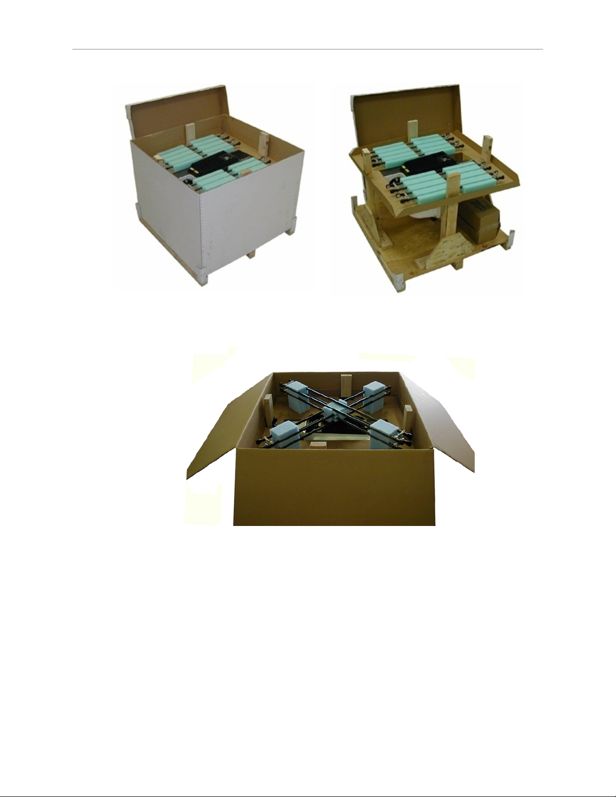
Figure 2-1. Shipping Crate (s650H shown)
Figure 2-2. Outer Arms for the Quattro s800 (s800Hshown)
The robot base is shipped with the inner arms attached. The outer arms are
shipped separate from the robot base, assembled in pairs. The platform is
shipped fully assembled, but separate from the robot base and outer arms.
Under the robot base, the ancillary items will be attached to the crate bottom.
2.
Lift off the cardboard sides.
3.
Remove the lag bolts holding the robot base to the crate sides.
Adept Quattro User's Guide, Rev F
Page 28 of 196
Page 29
Chapter 2: Robot Installation - H
2.3 Repacking for Relocation
If the robot or other equipment needs to be relocated, reverse the steps in the installation
procedures in this chapter. Reuse all original packing containers and materials and follow all
safety notes used for installation. Improper packaging for shipment will void your warranty.
CAUTION:The robot must always be shipped in an
upright orientation.
2.4 Environmental and Facility Requirements
The Adept Quattro robot system installation must meet the operating environment
requirements shown in the following table.
Table 2-1. Robot System Operating Environment Requirements
Ambient temperature 1 to 40° C (34 to 104° F)
Humidity 5 to 90%, non-condensing
Altitude up to 2000 m (6500 ft)
Pollution degree 2
Protection class: robot base IP-65 (with optional cable sealing kit)
Protection class: arms, platform IP-67
Note: For robot dimensions, see Technical Specifications on page 111.
Note: For power requirements, see Connecting 24 VDC Power to Robot on page 76 and
Connecting 200-240 VAC Power to Robot on page 79.
Note: The Adept SmartController must be installed inside a NEMA-1 rated enclosure. The
controller must not come into contact with liquids.
2.5 Mounting Frame
The Adept Quattro robot is designed to be mounted above the work area suspended on a usersupplied frame. The frame must be adequately stiff to hold the robot rigidly in place while the
robot platform moves within the workspace.
While Adept does not offer robot frames for purchase, and the frame design is the
responsibility of the user, we provide here some general guidelines as a service to our users.
Adept makes no representation or warranty with respect to these guidelines, or the rigidity and
longevity of the structure designed and built by the user or for the user by a third party using
these guidelines. In addition, when the robot is mounted on the structure based on these
guidelines, Adept does not guarantee that the robot will perform to the specifications given in
this product documentation, due to user’s frame or user’s production environmental factors.
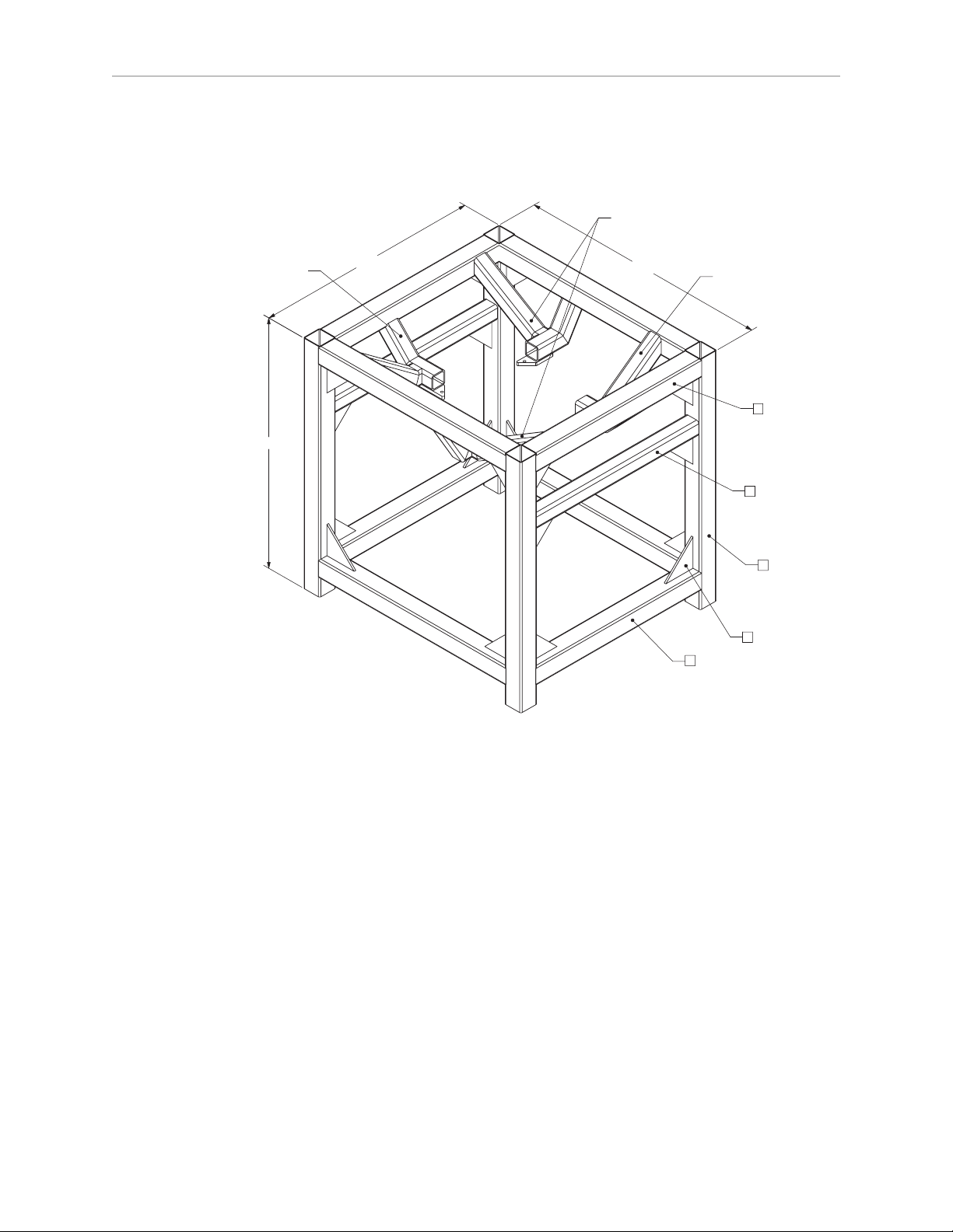
As an example, a sample frame design is presented and discussed. For generalized application
performance, frames built to the specifications of this sample should experience no
Adept Quattro User's Guide, Rev F
Page 29 of 196
Page 30
Chapter 2: Robot Installation - H
* DIMENSIONS ARE IN MILLIMETERS
U
NLESS OTHERWISE SPECIFIED:
MATERIAL : 300 SERIES STAINLESS STEEL
MATERIAL SIZING:
150mm X 150mm X 6mm SQUARE STRUCTURAL TUBINGA.
120mm X 120mm X 10mm SQUARE STRUCTURAL TUBINGB.
250mm X 250mm X 15mm TRIANGULAR GUSSETC.
A
4x
A
4x
2x
B
SEE DETAIL 1
20x
A
4x
C
SEE DETAIL 2
SEE DETAIL 1
1800.0
2000.0
2000.0
degradation in robot performance due to frame motions. Applications requiring higher than 6
kg * 10 g forces across the belt and/or 6 kg * 3 g along the belt may require a stiffer frame
design.
Figure 2-3. Sample Quattro Mounting Frame
NOTE:More specifications for the sample frame are provided in Robot Mounting
Frame, Quattro s650H Robot on page 124.
Any robot’s ability to settle to a fixed point in space is governed by the forces, masses, and
accelerations of the robot. Since “every action has an equal and opposite reaction”, these forces
are transmitted to the robot frame and cause the frame and base of the robot to move and
possibly vibrate in space. As the robot system works to position the tool flange relative to the
base of the robot, any frame or base motion will be “unobservable” to the robot system, and
will be transmitted to the tool flange. This transmitted base motion will result in inertial
movement of the tool flange mass, and will cause disturbance forces to be introduced into the
robot control system. These disturbance forces cause “work” to be done by the robot servo
control system which may result in longer settling times for robot operations.
Adept Quattro User's Guide, Rev F
Page 30 of 196
Page 31

Chapter 2: Robot Installation - H
It is important to note that, even after the system reports the robot to be fully settled, the tool
flange will still be moving by any amount of motion that the suspended base of the robot may
be experiencing.
Frame Orientation
The sample robot frame design is stiffer in one direction than the other. This is to
accommodate conveyor belt applications where the robot is moving with much more
acceleration across a conveyor belt than along it. The conveyor should generally be aligned so
that the belt travel is along the robot World Y-axis, and the mid-height frame members cross
the belt at a 90° angle. The across-the-belt dimension of the frame should be minimized to get
the best performance of the robot in that direction. While this frame design assumes a 1.8 m
across-the-belt frame dimension, a 1.5 m dimension would offer increased stiffness and
possibly increased robot performance at high accelerations and payloads. The mid-height
horizontal members are important to the frame stiffness, and should be located as close to the
belt as possible.
For applications requiring high accelerations along the direction of belt travel, consideration
should be given to strengthening the frame in that direction.
Frame Construction
Typically, the frame is constructed of welded steel members. Hygiene-sensitive applications
may call for stainless steel fabrication, with care taken to seal up all possible voids and grind
smooth all weld joints. For other applications, it may be suitable to manufacture the frame of
carbon steel and paint the resulting assembly. The frame design presented here is based on a
stainless steel construction using 10 mm thick members. It may be reasonable to use a reduced
thickness for carbon steel assemblies. Some customers may choose to use tubular members, or
turn horizontal members at 45° angles to facilitate water runoff from the flat frame surfaces.
Robot-to-Frame Considerations
The Quattro has a moderately-complex mounting requirement due to the nature of the parallelarm kinematics and the need to minimize the robot size and mass. Arm Travel Volume (s650
shown) on page 118 shows the inner arm travel and how it may encroach on the robot
mounting points. As a starting point, for a frame that is 2 meters in each direction, (allowing
use of the full range of the Quattro s650 robots), you should attempt to attain a frame
frequency of 25 Hz.
For specialized applications, such as heavy payloads and/or aggressive moves, you may want
to attain a frame frequency of 40 Hz.
In general, a smaller frame will yield a higher frequency. If you aren’t going to use to entire
work envelope, you can increase the frequency simply by using a smaller frame.
A lower frequency frame, more aggressive robot moves, and heavier payloads will all
contribute to longer settling times.
Mounting
The robot mounts in four locations, as detailed in the drawings. The holes are tapped for an
M16 x 2.0 bolt. The Adept Quattro robot may be mounted from the top or bottom of the frame.
A crane or forklift should be used to position the robot. If lifted from above, the robot must be
lifted by user-supplied eyebolts and slings.
Adept Quattro User's Guide, Rev F
Page 31 of 196
Page 32

Chapter 2: Robot Installation - H
Figure 7-2 shows the mounting hole pattern for the Adept Quattro robot. Note the hole location
and mounting pad tolerances for position and flatness.
Deviation from this flatness specification will, over time, cause a possible loss of robot
calibration. If the frame does not meet this flatness specification, use shims to achieve it.
NOTE:Adept suggests welding the robot mounting tabs as a last step in the frame
fabrication, using a flat surface as a datum surface during the tack welding
operation.
Gussets
The triangular gussets are an integral part of the frame stiffness. The vibrational strength of a
structural assembly is strongly governed by controlling the shear forces between members. The
250 mm gussets, shown in Figure 2-3, are nominally sufficient for transferring the load from
the vertical members into the horizontal cross pieces. Preferably, gussets should be placed at
the edges of the frame members to transfer the loading into the walls of the members, instead
of the faces, and enable easier cleaning. Some frame designs may benefit from extending these
gussets to 500 mm in the vertical direction, as the design intent of the gussets is mainly to
secure the long vertical members from rotating out of position. For this reason, the gussets to
the across-the-belt horizontal member should be at the bottom of the member, as shown in
Figure 2-3, and as close to the vertical midplane of the frame as feasible (15 mm thickness is
adequate for most situations).
2.6 Mounting the Robot Base
NOTE:All mounting hardware is user-supplied.
CAUTION:Remove all ancillary components (controller,
outer arms, platform, etc.) from the shipping crate before
lifting the robot base.
Robot Orientation
Adept recommends mounting the Adept Quattro robot so that the Status Display Panel faces
away from the conveyor belt. Although the work envelope of the robot is symmetrical, this
orientation gives better access to the status display, status LED, and Brake-Release button. It
also balances the arm loading for aggressive moves across the belt.
This orientation places the robot World Y-axis along the conveyor belt, and the X-axis across
the belt.
Mounting Surfaces
Mounting surfaces for the robot mounting flanges must be within 0.75 mm of a flat plane. If
the surfaces do not meet this tolerance, use shims to attain it.
CAUTION:Failure to mount the Quattro robot within
0.75mm of a flat plane will result in inconsistent robot
motions.
Adept Quattro User's Guide, Rev F
Page 32 of 196
Page 33

Chapter 2: Robot Installation - H
Mounting Options
Using the mounting frame design provided by Adept, there are several options for mounting
the Adept Quattro robot:
l
Lower the robot into the frame from above, or
Lift the robot into the frame from below.
l
Place the robot mounting pads on top of the frame mounting pads, or
Place the robot mounting pads under the frame mounting pads.
l
Mounting hardware can be bolts threaded directly into the robot base mounting pads,
or bolts that go through the robot base mounting pads into nuts.
CAUTION:Do not attempt to lift the robot from any
points other than with eyebolts or slings as described
here, or with a padded board, as described here.
Mounting Procedure from Above the Frame
The Adept Quattro robot has four mounting pads. Each pad has one M16 x 2.0 threaded
through-hole. The robot can be mounted either on top of the frame pads, using the bottom
surface of the robot base mounting pads, or to the bottom of the frame pads, using the top
surface of the robot base mounting pads.
Mounting to Top of Frame Pads
This procedure uses two user-supplied M16 x 2.0 eyebolts and jam nuts.
1.
Remove all lag bolts from the robot base mounting pads.
2.
Screw the M16 eyebolts into opposing robot mounting pads, so that the robot will be
balanced when lifted.
3.
Lock each eyebolt with a jam nut.
4.
Connect slings to the M16 eyebolts and take up any slack in the slings.
CAUTION:Do not attempt to lift the robot from any
points other than the eyebolts. Failure to comply could
result in the robot falling and causing either personnel
injury or equipment damage.
5.
Lift the robot and position it directly over the mounting frame.
6.
Slowly lower the robot while aligning the M16 holes in the robot mounting pads with
the holes in the frame mounting pads.
7.
When the mounting pad surfaces are touching, start a bolt in each of the two unused
mounting holes. Refer to Install Mounting Hardware on page 35.
8.
Remove the slings and M16 eyebolts.
9.
Follow the instructions in Install Mounting Hardware on page 35.
Adept Quattro User's Guide, Rev F
Page 33 of 196
Page 34

Chapter 2: Robot Installation - H
Mounting to Bottom of Frame Pads
NOTE:Since eyebolts would be in the way of this mounting method, you will have
to use slings or other means to lift the robot base. Nylon slings can be wrapped
across the center of the robot base, away from the inner arms. See the following
figure.
1.
Remove all lag bolts from the mounting pads before lifting the robot base.
2.
Wrap slings around the robot base. See the following figure for two methods.
NOTE: Make sure the slings do not touch the status panel or inner arms.
Figure 2-4. Location of Slings for Lifting Robot Base
3.
Lift the robot and position it directly over the mounting frame.
4.
Slowly lower the robot while rotating it slightly, so that the four mounting pads are
lowered past the frame mounting pads without touching.
5.
When the robot base mounting pads are below the lower surface of the frame mounting
pads, rotate the robot base so that the M16 threaded holes in the robot base mounting
pads align with the holes in the frame mounting pads.
6.
Lift the robot base up, keeping the holes in the robot base pads and the frame pads
aligned, until the top surfaces of the robot base pads are touching the bottom surface of
the frame mounting pads.
7.
Follow the instructions in Install Mounting Hardware on page 35.
Mounting Procedure from Below the Frame
The Adept Quattro robot has four mounting pads. Each pad has one M16 x 2.0 threaded hole.
The robot can be mounted either on top of the frame pads, using the bottom surface of the
Adept Quattro User's Guide, Rev F
Page 34 of 196
Page 35

Chapter 2: Robot Installation - H
robot base pads, or to the bottom of the frame pads, using the top surface of the robot base
pads.
The Adept Quattro robot can be mounted from beneath the mounting frame using a forklift.
Use a padded board as a support under the robot base. The robot base can be rotated by hand,
once mounted on the lifting pad on a forklift, when needed for clearing obstacles.
Mounting to Bottom of Frame Pads
1.
Remove all lag bolts from the mounting pads before lifting the robot base.
2.
Lift the robot and position the robot directly under the mounting frame.
3.
Slowly lift the robot and align the M16 holes in the robot mounting pads with the holes
in the frame mounting pads.
4.
Lift the robot until the top of the robot base mounting pads are touching the bottom of
the frame mounting pads.
5.
Follow the instructions in Install Mounting Hardware on page 35.
Mounting to Top of Frame Pads
1.
Remove all lag bolts from the mounting pads before lifting the robot base.
2.
Lift the robot so the mounting pads are directly under the mounting pads of the frame.
3.
Slowly lift the robot while rotating it slightly, so that the four mounting pads are raised
past the frame mounting pads without touching.
4.
When the robot base mounting pads are above the top surface of the frame mounting
pads, rotate the robot base back, so that the M16 threaded holes in the robot base
mounting pads align with the holes in the frame mounting pads.
5.
Slowly lower the robot base while aligning the M16 holes in the robot mounting pads
with the holes in the frame mounting pads.
6.
Continue lowering the robot base until the bottom surface of the robot base mounting
pads are touching the top surface of the frame mounting pads.
7.
Follow the instructions in Install Mounting Hardware on page 35.
Install Mounting Hardware
NOTE:When mounting the robot, note the following:
l
The base casting of the robot is aluminum and can be dented if bumped against a
harder surface.
l
Verify that the robot is mounted squarely before tightening the mounting bolts.
l
All mounting hardware is user-supplied.
1.
Place split lock, then flat washers on the bolts.
Bolts are M16 x 2.0 if threaded into the robot base mounting tabs.
Bolts are M12 or ½ in. if going through the robot base mounting tabs into nuts.
Adept Quattro User's Guide, Rev F
Page 35 of 196
Page 36

Chapter 2: Robot Installation - H
NOTE:When M16 x 2.0 bolts are used, the bolt must engage at least 24 mm into
the threads of the base mounting pad.
2.
Insert the bolts through the holes in the frame mounting pads and into the threaded
holes in the robot base mounting pads.
If using through-bolts, insert the bolts through the holes in both the mounting pads and
through the threaded holes in the robot base mounting pads into nuts.
3.
Tighten the mounting hardware to the specifications listed in the following table.
NOTE:Check the tightness of the mounting bolts one week after initial installation,
and then recheck every 6 months. For periodic maintenance, see Periodic
Maintenance Schedule on page 131.
Table 2-2. Mounting Bolt Torque Specifications
Standard Size Minimum Specification Torque
Threaded into base (aluminum):
Metric M16 x 2.0 ISO Property Class 5.8 98 N·m (74 ft-lb)
Using base mounting pad hole as through-hole:
Metric M12 ISO Property Class 9.8 100 N·m (75 ft-lb)
SAE ½ in. 100 N·m (75 ft-lb)
Adept Quattro User's Guide, Rev F
Page 36 of 196
Page 37

Chapter 2: Robot Installation - H
Outer
Arms
Platform
(sp
rings not
shown)
Cable Cover
(IP-65 option)
Inner
Arms
Motor
Cover
AIB
Mounting
Pads
Base
Ball Joints
(springs not
shown)
2.7 Attaching the Outer Arms and Platform
Figure 2-5. Major Robot Components, Top View
The Adept Quattro robot platform is attached to the inner arms by the outer arms.
NOTE:Except for attaching the outer arms and end-effector tooling, the platform is
shipped fully assembled.
Clocking the Platform to the Base
The rotational alignment (clocking) of the platform to the base is critical to the correct
operation of the Adept Quattro robot.
CAUTION:Incorrect clocking of the platform will result
in incorrect robot performance.
l
On the hard-anodized and stainless steel platforms, the ends of the platform crosspieces (between each pair of ball studs) are labeled with numbers (1–4).
Adept Quattro User's Guide, Rev F
Page 37 of 196
Page 38

Chapter 2: Robot Installation - H
In addition, +X and +Y World Coordinates are labeled on the platform near the flange.
See Figure 2-6.
l
Electroless nickel platforms are not labeled. Refer to Figure 2-7.
l
When installing the platform, the numbers on the platform must match the numbers on
the underside of the robot base.
Figure 2-6. Platform Orientation Labeling (P34 shown)
NOTE:The labeling on all anodized platforms is the same except for the part
number.
Adept Quattro User's Guide, Rev F
Page 38 of 196
Page 39

Chapter 2: Robot Installation - H
X+
Y+
3
41
2
T
ool Flange
Figure 2-7. Platform Orientation, P31 Platform
Attaching the Outer Arms
One pair of outer arms attaches between each inner arm and the platform. No tools are needed
to install or remove the outer arms.
l
Each outer arm has a ball joint socket at each end.
l
The inner arms and the platform have corresponding pairs of ball studs.
Figure 2-8. Inner Arm Ball Studs
Adept Quattro User's Guide, Rev F
Page 39 of 196
Page 40

Chapter 2: Robot Installation - H
WARNING:Pinch hazard. Ball joints are spring-loaded.
Be careful not to pinch your fingers.
l
Outer arm pairs are shipped assembled. Each pair has two springs and two horseshoes
at each end.
Figure 2-9. Ball Joint Assembly (Quattro HS shown)
CAUTION:Ensure that the bearing insert is in place in the end of
each outer arm. If an insert has fallen out of the arm, press it back
into place, ensuring that the insert is centered and bottomed-out in
the ball joint socket.
NOTE:In the following steps, take care not to trap debris between the ball studs
and their sockets.
NOTE: The procedure for attaching outer arms is the same for all platforms.
1.
Attach one pair of outer arms to each inner arm.
a.
As illustrated in the following figure, this is most easily achieved by pivoting the
two arms away from each other lengthwise.
This requires the least stretching of the spring to attach the ball joints.
b.
Slip one ball joint socket over the corresponding ball stud.
Adept Quattro User's Guide, Rev F
Page 40 of 196
Page 41

Chapter 2: Robot Installation - H
c.
Swing the bottom end of the outer arm pair sideways as you slip the other ball
joint socket over the corresponding ball stud.
CAUTION:Do not overstretch the outer arm springs.
Separate the ball joint sockets only enough to fit them
over the ball studs.
Figure 2-10. Installing Outer Arms
2.
Attach one pair of outer arms to each of the four pairs of ball studs on the platform.
NOTE:Ensure that the numbers on the platform match the numbers on the
underside of the robot base. This will place the platform tool flange closest to the
Status Display Panel. See Clocking the Platform to the Base on page 37. The
platform is installed flange-down.
a.
Swing the bottom end of the outer arm pair to the right, as far as possible.
b.
Slip the right ball joint socket over the right ball stud. (Move the platform
as needed to do this.)
c.
Move the platform and outer arm pair to the left as you slip the left ball
joint socket over the corresponding ball stud.
3.
Ensure that all spring hooks are fully-seated in the grooves of the horseshoes, as shown
in the following figure:
Adept Quattro User's Guide, Rev F
Page 41 of 196
Page 42

Chapter 2: Robot Installation - H
Figure 2-11. Horseshoe and Spring Assembly
Adept Quattro User's Guide, Rev F
Page 42 of 196
Page 43

Chapter 3: Robot Installation - HS
3.1 Transport and Storage
This equipment must be shipped and stored in a temperature-controlled environment, within
the range –25 to +55° C (-13 to 131° F). The recommended humidity range is 5 to 90 percent,
non-condensing. It should be shipped and stored in the Adept-supplied crate, which is
designed to prevent damage from normal shock and vibration. You should protect the crate
from excessive shock and vibration.
Use a forklift, pallet jack, or similar device to transport and store the packaged equipment.
The robot must always be stored and shipped in an upright position in a clean, dry area that
is free from condensation. Do not lay the crate on its side or any other non-upright position.
This could damage the robot.
The Adept Quattro robot weighs 118 to 123 kg (260 to 271 lb) with no options installed.
3.2 Unpacking and Inspecting the Adept Equipment
Before Unpacking
Carefully inspect all shipping crates for evidence of damage during transit. If any damage is
indicated, request that the carrier’s agent be present at the time the container is unpacked.
Upon Unpacking
Before signing the carrier’s delivery sheet, compare the actual items received (not just the
packing slip) with your equipment purchase order. Verify that all items are present and that
the shipment is correct and free of visible damage.
l
If the items received do not match the packing slip, or are damaged, do not sign the
receipt. Contact Adept as soon as possible (see How Can I Get Help? on page 25).
l
If the items received do not match your order, please contact Adept immediately.
Retain all containers and packaging materials. These items may be necessary to settle claims
or, at a later date, to relocate the equipment.
Unpacking
The Quattro HS robot is shipped in a crate that holds the robot base, outer arms, platform,
controller, miscellaneous hardware, and any accessories ordered. The crate will be combined
wood and cardboard.
The top of the crate should be removed first.
1.
Remove the bands holding the top to the rest of the crate. Refer to the following figure.
The outer arms will be above the robot base. These should be removed from the crate,
followed by the cardboard and foam that support them.
Adept Quattro User's Guide, Rev F
Page 43 of 196
Page 44

Chapter 3: Robot Installation - HS
NOTE:Outer arms for the Quattro s800HS robot are packaged differently from these
illustrations. See Figure 3-2.
Figure 3-1. Quattro Shipping Crate (Quattro s650H shown)
Figure 3-2. View of crate with s800 Outer Arms (s800H shown)
The robot base is shipped with the inner arms attached. The outer arms are
shipped assembled in pairs; the platform is shipped fully assembled, but
separate from the robot base and outer arms.
Under the robot base, the ancillary items will be attached to the crate bottom.
Adept Quattro User's Guide, Rev F
Page 44 of 196
Page 45

Chapter 3: Robot Installation - HS
2.
Lift off the cardboard sides.
Under the robot base, the ancillary items will be attached to the crate bottom. Refer to
the preceding figure.
Figure 3-3. L-Bracket Securing Robot to Shipping Crate
The robot base is held in place in the crate with L-brackets and machine bolts.
1.
Place a protective pad over the AIB/eAIB to protect it from damage from tools during
the removal of the L-brackets.
2.
Remove the three hex-head wood screws (0.25 in.) from each bracket.
Retain the wood screws and washers for possible future relocation.
3.
Remove the M16 bolt and lock and flat washers from each bracket.
Retain the M16 bolts and lock and flat washers for possible future relocation.
NOTE:These are not the M16 bolts used for mounting the robot.
3.3 Repacking for Relocation
If the robot or other equipment needs to be relocated, reverse the steps in the installation
procedures that follow in this chapter. Reuse all original packing containers and materials and
follow all safety notes used for installation. Improper packaging for shipment will void your
warranty.
Adept Quattro User's Guide, Rev F
Page 45 of 196
Page 46

Chapter 3: Robot Installation - HS
CAUTION:The robot must always be shipped in an
upright orientation.
3.4 Environmental and Facility Requirements
The Quattro HS robot system installation must meet the operating environment requirements
shown in the following table.
Table 3-1. Robot System Operating Environment Requirements
Ambient temperature 1 to 40° C (34 to 104° F)
Humidity 5 to 90%, non-condensing
Altitude up to 2000 m (6500 ft)
Pollution degree 2
Protection class: robot base IP-66
Protection class: platform, arms IP-67
NOTE: For robot dimensions, see Top Dimensions, s650 and s800 Robots on page 111.
NOTE: For power requirements, see Connecting 24 VDC Power to Robot on page 76 and
Connecting 200-240 VAC Power to Robot on page 79.
NOTE: The Adept SmartController must be installed inside a NEMA-1 rated enclosure. The
controller must not come into contact with liquids.
NOTE: For chemical cleaning information, refer to Chemical Compatibility on page 154.
3.5 Mounting Frame
The design of the robot mounting frame is the user’s responsibility.
l
The sample given for the s650H robot, while stiff enough for use with the Quattro HS
robots, was not designed for USDA applications.
l
The thickness of the frame mounting tabs is critical, as is the flatness of those tabs. See
Frame Mounting Tabs (following) and Mounting Surfaces on page 55.
l
The frame must be stiff enough to prevent excessive vibration.
l
You may want to design the frame so that the robot can be installed by lowering it from
the top.
The Quattro HS robot is designed to be mounted above the work area suspended on a usersupplied frame. The frame must be adequately stiff to hold the robot rigidly in place while the
robot platform moves within the workspace.
While Adept does not offer robot frames for purchase, and the frame design is the
responsibility of the user, we provide some general guidelines as a service to our users.
Adept Quattro User's Guide, Rev F
Page 46 of 196
Page 47

Chapter 3: Robot Installation - HS
Any robot’s ability to settle to a fixed point in space is governed by the forces, masses, and
accelerations of the robot. Since “every action has an equal and opposite reaction”, these forces
are transmitted to the robot frame and cause the frame and base of the robot to move and
possibly vibrate in space. As the robot system works to position the tool flange relative to the
base of the robot, any frame or base motion will be “unobservable” to the robot system, and
will be transmitted to the tool flange. This transmitted base motion will result in inertial
movement of the tool flange mass, and will cause disturbance forces to be introduced into the
robot control system. These disturbance forces cause “work” to be done by the robot servo
control system which may result in longer settling times for robot operations.
It is important to note that, even after the system reports the robot to be fully settled, the tool
flange will still be moving by any amount of motion that the suspended base of the robot may
be experiencing.
Frame Mounting Tabs
To achieve the correct compression of the sealing gaskets, the mounting tabs on the frame
must be 12.7 mm, +1.3, -0.7 mm thick (0.5 in., +0.05, -0.028 in.).
Because the junction of the robot base mounting pad and the frame mounting pad is sealed
with a gasket, the frame mounting pads must be at least as big as the robot base mounting
pads. If the frame pad does not cover the entire robot pad, the gasket will not seal properly.
The design of the Quattro HS robot mounting bolts and seals requires fairly tight tolerances for
the robot mounting holes in the frame. These should be 17.25 ± 0.75 mm (0.68 ± 0.03 in.) in
diameter.
Robot-to-Frame Considerations
The Quattro robot has a moderately-complex mounting requirement due to the nature of the
parallel-arm kinematics and the need to minimize the robot size and mass. Arm Travel
Volume (s650 shown) on page 118 shows the inner arm travel and how it may encroach on
the robot mounting points. As a starting point, for a frame that is 2 meters in each direction,
(allowing use of the full range of the Quattro s650 robots), you should attempt to attain a frame
frequency of 25 Hz.
For specialized applications, such as heavy payloads and/or aggressive moves, you may want
to attain a frame frequency of 40 Hz.
In general, a smaller frame will yield a higher frequency. If you aren’t going to use to entire
work envelope, you can increase the frequency simply by using a smaller frame.
A lower frequency frame, more aggressive robot moves, and heavier payloads will all
contribute to longer settling times.
Mounting
Mounting Hole Dimensions, Quattro HS Robots on page 113 shows the mounting hole pattern
for the Quattro HS robot. Note the hole location and mounting pad tolerances for position and
flatness.
Deviation from this flatness specification will, over time, cause a possible loss of robot
calibration.
Adept Quattro User's Guide, Rev F
Page 47 of 196
Page 48

NOTE:Adept suggests welding the robot mounting tabs as a last step in the frame
fabrication, using a flat surface as a datum surface during the tack welding
operation.
Gussets
The triangular gussets are an integral part of the frame stiffness. The vibrational strength of a
structural assembly is strongly governed by controlling the shear forces between members. The
250 mm gussets, shown in Figure 2-3, are nominally sufficient for transferring the load from
the vertical members into the horizontal cross pieces. Preferably, gussets should be placed at
the edges of the frame members to transfer the loading into the walls of the members, instead
of the faces, and enable easier cleaning. Some frame designs may benefit from extending these
gussets to 500 mm in the vertical direction, as the design intent of the gussets is mainly to
secure the long vertical members from rotating out of position. For this reason, the gussets to
the across-the-belt horizontal member should be at the bottom of the member, as shown in
Figure 2-3, and as close to the vertical midplane of the frame as feasible (15 mm thickness is
adequate for most situations).
3.6 Cable Inlet Box
Chapter 3: Robot Installation - HS
The cable inlet box (P/N 09564-000) must be mounted on the top of the robot during the robot
installation process. This is best done before the robot is mounted on the frame.
Assembling Cable Inlet Box
The cables entering the cable inlet box are sealed with a Roxtec compression block kit.
Figure 3-4. Cable Inlet Box and Cover
Adept Quattro User's Guide, Rev F
Page 48 of 196
Page 49

Components
l
Cable Inlet box
l
Cable Inlet box cover
l
Cable Inlet box-cover gasket
l
Cable Inlet box-AIB/eAIB gasket
l
Compression Block kit - Roxtec CF 8-8
NOTE:The Roxtec CF 8 consists of a frame and integrated compression unit (a
wedge and bolt that compress the modules once they are assembled inside the CF
frame). See Figure 3-10.
Chapter 3: Robot Installation - HS
l
Roxtec CF 8 frame
l
4 x 2-hole Roxtec modules
These are dense foam blocks surrounding pre-cut half-sleeves that can be peeled
away to match the diameter of the cable to be sealed. The installation procedure
follows.
l
Roxtec grease, used to assemble and seal the modules.
Tasks
l
4 x Screws, M4 x 40 (cable box-AIB/eAIB; one is used for the ground)
l
1 x Washer, ETL, SS M4 (for ground screw)
l
4 x Screws, M4 x 16 mm (for the back cover)
l
4 x Washer seals (for the back cover screws)
l
4 x Screws, M4 x 12 mm (for attaching the cable tray)
The following may be included as spares:
l
4 x Screws, M4 x 16 mm (for the cable tray)
l
4 x Washer seals (for the cable tray screws)
l
4 x Washers, ETL, SS M4 (for the cable tray)
1.
Measure and mark cables to establish service length
2.
Adapt Roxtec modules to fit cables
3.
Install cables through cable inlet box (via Roxtec modules)
4.
Attach cables to AIB/eAIB
5.
Install AIB/eAIB cable inlet box
6.
Attach cable inlet box back cover
Adept Quattro User's Guide, Rev F
Page 49 of 196
Page 50

Procedure
1. Measure and mark all AIB/eAIB cables at 10 - 12 in. from the cable ends.
Chapter 3: Robot Installation - HS
This amount of slack is needed to make the cable connections to the AIB/eAIB before the
cable inlet box is installed. See Figure 3-10.
Figure 3-5. Quattro HS Cable Inlet Box with Roxtec Frame
2. Adapt Roxtec modules to fit the cables that will be used. There should be a 0.1 to 1.0
mm gap between the halves of the modules for a proper seal. See the following figure.
Figure 3-6. Adapting a Module to the Cable Size, Checking the Gap
3. Grease the Roxtec modules, using Roxtec grease. See the following figure.
Adept Quattro User's Guide, Rev F
Page 50 of 196
Page 51

Chapter 3: Robot Installation - HS
Figure 3-7. Greasing a Roxtec Module
4.
Grease the inside of the CF frame, where the modules will touch, using Roxtec grease.
5.
Install each AIB/eAIB cable through its corresponding module, and insert the modules
into the frame. See the following figure. Ensure that the terminated cable ends have 10 12 in. of slack. See Figure 3-10.
Figure 3-8. Installing Roxtec Modules into the Frame
When all of the modules are in place, tighten the compression unit to 8 - 12 N·m (6-9 ft-lbf).
See the following two figures. There should be no visible gaps between the modules or around
the cables.
Figure 3-9. Tightening the Compression Unit
Adept Quattro User's Guide, Rev F
Page 51 of 196
Page 52

Chapter 3: Robot Installation - HS
Figure 3-10. Cable Inlet Box with Cables
In the preceding figure, note the four holes around the Roxtec box. These are for attaching a
cable tray. See Attaching the Cable Tray on page 64.
Adept Quattro User's Guide, Rev F
Page 52 of 196
Page 53

Connecting the Cables
1.
Place the cable inlet box-AIB/eAIB gasket around the AIB/eAIB connection panel.
2.
Attach the ground lug to the AIB/eAIB. The ground lug is for the cable shield of the
user-supplied 24 VDC cable. See the following figure.
Chapter 3: Robot Installation - HS
Figure 3-11. Cable Shield Ground Lug Attachment, AIB Shown
3.
Hand-tighten all cables to the AIB/eAIB.
NOTE:All cables must be screwed into the AIB/eAIB.
The protective earth ground will be installed in the following section.
Installing the Cable Inlet Box
1.
Install the cable inlet box on the top of the AIB/eAIB using three M4 x 40 bolts.
l
Ensure that the gasket is seated between the AIB/eAIB surface and the cable inlet
box.
l
Do not yet use the hole labeled as a ground.
l
Apply Loctite 222 in these bolt holes, not on the bolts themselves.
l
Torque the bolts to 1.1 N·m (10 in-lb).
NOTE:The cable inlet box should be installed with the cables exiting away from
the AIB/eAIB. The cable tray attachment was designed assuming the cables would
exit away from the AIB/eAIB.
Adept Quattro User's Guide, Rev F
Page 53 of 196
Page 54

Chapter 3: Robot Installation - HS
Ground bolt
and label
Figure 3-12. Cable Inlet Box, showing Ground Label
2.
Install the M4 protective earth ground bolt, with toothed washer, through the cable inlet
box into the AIB/eAIB. See the preceding figure.
l
Ensure that the protective earth ground wire lug is under the toothed washer.
l
This bolt does not need Loctite.
l
Torque the bolt to 1.1 N·m (10 in-lb).
3.
Attach the cable inlet box back cover with four M4 x 16 bolts.
l
Ensure that the gasket is seated between the cover and the cable inlet box.
l
Put one washer seal under each bolt head.
l
Use Loctite 222 in these bolt holes, not on the bolts themselves.
l
Torque bolts to 1.1 N·m (10 in-lb).
Adept Quattro User's Guide, Rev F
Page 54 of 196
Page 55

Chapter 3: Robot Installation - HS
3.7 Mounting the Robot Base
CAUTION:Remove all ancillary components (controller,
outer arms, platform, etc.) from the shipping crate before
lifting the robot base.
Robot Orientation
Adept recommends mounting the Quattro HS robot so that the Status Display Panel faces
away from the conveyor belt. Although the work envelope of the robot is symmetrical, this
orientation gives better access to the status display, status LED, and Brake-Release button. It
also balances the arm loading for aggressive moves across the belt.
This orientation places the robot World Y-axis along the conveyor belt, and the X-axis across
the belt.
Because USDA requirements do not allow external sticker labels, the motor numbers of the
electroless nickel platforms are not labeled on the platforms.
Mounting Surfaces
Mounting surfaces for the robot mounting tabs must be within 0.75 mm of a flat plane.
CAUTION:Failure to mount the Quattro robot within
0.75mm of a flat plane will result in inconsistent robot
locations.
Because the junction of the robot base mounting pad and the frame mounting pad is sealed
with a gasket, the frame mounting pads must be at least as big as the robot base mounting
pads.
NOTE:If the frame pad does not cover the entire robot pad, the gasket will not seal
properly.
Mounting Options
NOTE:The base casting of the robot is aluminum and can be dented if bumped
against a harder surface.
NOTE: Because of USDA requirements, the mounting holes in the robot base
mounting tabs are not through-holes. This eliminates the possibility of mounting
the robot with the robot tabs on top of the frame tabs. This is different than the
Quattro H robots.
Adept Quattro User's Guide, Rev F
Page 55 of 196
Page 56

Chapter 3: Robot Installation - HS
Slings
Slings
Depending on the mounting frame design used, there may be two options for mounting the
Quattro HS robot:
l
Lower the robot into the frame from above
or
l
Lift the robot into the frame from below
CAUTION:Do not attempt to lift the robot from any
points other than with slings as described here, or with a
padded board, as described here.
The Quattro HS robot has four mounting pads. Each pad has one M16x2.0 threaded hole. The
robot must be mounted to the bottom of the frame pads, using the top surface of the robot base
mounting pads.
Mounting Procedure from Above the Frame
NOTE:Nylon slings can be wrapped across the center of the robot base, away from
the inner arms. See the following figure.
1.
Remove all wood screws, machine bolts, and brackets securing the robot to the crate
before lifting the robot base.
Retain the removed hardware for future packing of the robot for relocation.
2.
Wrap slings around the robot base. See the following figure for two methods.
NOTE:Make sure the slings do not touch the status panel or inner arms.
Figure 3-13. Location of Slings for Lifting Robot Base
Adept Quattro User's Guide, Rev F
Page 56 of 196
Page 57

Chapter 3: Robot Installation - HS
Sealing gasket
Robot Base
Raised Area
(limits gasket
compression)
M16
Hole
3.
Insert a base-pad sealing-gasket into the groove machined in each robot base mounting
pad. The gasket and its positioning are shown in the following figure.
Figure 3-14. Robot Base Pad Sealing Gasket, Top View
The area of the mounting pad surrounded by the groove serves as a spacer, to
ensure that the sealing gasket is properly compressed.
4.
Lift the robot and position it directly over the mounting frame.
5.
Slowly lower the robot while rotating it slightly, so that the four mounting pads are
lowered past the frame mounting pads without touching.
6.
When the robot base mounting pads are below the lower surface of the frame mounting
pads, rotate the robot base so that the M16 threaded holes in the robot base mounting
pads align with the holes in the frame mounting pads.
7.
Lift the robot base up, keeping the holes in the robot base pads and the frame pads
aligned, until the sealing gaskets are touching the bottom surfaces of the frame
mounting pads.
8.
Follow the instructions in Install Mounting Hardware on page 58.
Mounting Procedure from Below the Frame
The Quattro HS robot can be mounted from beneath the mounting frame using a forklift. Use a
padded board as a support under the robot base. The robot base can be rotated by hand, once
supported by the lifting pad on a forklift, when needed for clearing obstacles.
1.
Remove all wood screws, machine bolts, and brackets securing the robot to the crate
before lifting the robot base.
Retain the removed hardware for future packing of the robot for relocation.
2.
Insert a base-pad sealing-gasket into the groove machined in each robot base mounting
pad. The gasket and its positioning are shown in Figure 3-14.
3.
4.
5.
Lift the robot and position it directly under the mounting frame.
Slowly lift the robot and align the M16 holes in the robot mounting pads with the holes
in the frame mounting pads.
Lift the robot base up, keeping the holes in the robot base pads and the frame pads
Adept Quattro User's Guide, Rev F
Page 57 of 196
Page 58

Chapter 3: Robot Installation - HS
Mounting Bolt Detail
316 Stainless Steel
Mounting Bolt Spacer
(DIN 6921 standard)
Mounting Bolt
M 16-2.0 X 40 mm lg.
Mounting Bolt
Sealing Gasket
aligned, until the gaskets on the top surfaces of the robot base pads are touching the
bottom surfaces of the frame mounting pads.
6.
Follow the instructions in Install Mounting Hardware on page 58.
Install Mounting Hardware
To achieve the correct compression of the sealing gaskets, the mounting tabs on the frame
must be 12.7 mm, +1.3, -0.7 mm (0.5 in., +0.05, -0.028 in.) thick.
If you choose to use a different frame pad thickness and provide your own mounting bolts, the
bolts need to be M16-2.0, 316 stainless steel flange bolt (DIN 6921 standard). The threads must
engage at least 24 mm (0.94 in.) of the robot base threads (HeliCoil), for sufficient support. The
bolts must not bottom out, or the washer seals and gaskets will not be compressed enough to
form a good seal.
When mounting the robot, note the following:
l
Verify that the robot is mounted squarely before tightening the mounting bolts.
l
Verify that the gaskets between the robot pads and the mounting frame are in their
grooves in the pads, and completely covered by the mounting frame pads.
l
USDA requires that all exposed screws be sealed with a gasket, which must be
compressed to specific standards. To achieve this, the Quattro HS robot mounting bolts
use a spacer that fits inside a compressible sealing gasket. See the following figure.
l
Place a spacer, then a sealing gasket, on each bolt.
Figure 3-15. Robot Mounting Bolt, Seal, and Gasket
l
Insert the bolts through the holes in the frame mounting pads and into the threaded
holes in the robot base mounting pads. See the following table for mounting bolt torque
specifications.
l
Check the position of the gaskets between the robot base pads and the mounting frame.
Adept Quattro User's Guide, Rev F
Page 58 of 196
Page 59

Chapter 3: Robot Installation - HS
Outer
A
rms
Platform
(P31 shown)
Cable Inlet Box
Inner
Arms
Motor
Cover
AIB
Mounting
Pads
Base
Ball Joints
and Spring
Assemblies
Status Display
Panel
The frame pads should completely cover the gaskets.
l
Tighten the bolts to 98 N·m (74 ft-lb).
NOTE:The robot base-mounting tabs have spring-lock HeliCoils in the M16 holes,
so a lock washer is not needed on the M16 mounting bolts.
NOTE: Check the tightness of the mounting bolts one week after initial installation,
and then recheck every 3 months. See Periodic Maintenance on page 154.
Table 3-2. Mounting Bolt Torque Specifications
Standard Size Minimum Specification Torque
Metric M16-2.0 x 40 mm ISO Property Class 5.8 98 N·m (74 ft-lb)
3.8 Attaching the Outer Arms and Platform
Figure 3-16. Major Robot Components, Top View
The Adept Quattro robot platform is attached to the inner arms by the outer arms.
NOTE:Except for attaching the outer arms and end-effector tooling, the platform is
shipped fully assembled.
Adept Quattro User's Guide, Rev F
Page 59 of 196
Page 60

Chapter 3: Robot Installation - HS
X+
Y+
3
41
2
T
ool Flange
Clocking the Platform to the Base
The rotational alignment (clocking) of the platform to the base is critical to the correct
operation of the robot.
CAUTION:Incorrect clocking of the platform will result
in incorrect robot performance.
NOTE:There is no marking on the electroless nickel-plated platforms to indicate
which pair of ball studs should be connected to which inner arm.
Stainless steel platforms are labeled.
When the platform is installed correctly, the tool flange will be closest to the status display on
the robot base.
NOTE: The tool flange face on the P30 platform is centered, so that platform can be
installed in any orientation.
The bottom of the robot base has embossed numbers, 1 through 4, indicating the motor
numbers. The corresponding numbers for the platform, as viewed from the top, are indicated
in the following figure, where each number represents a pair of ball studs. When the platform
numbers match the robot base numbers, the platform will be correctly aligned.
Figure 3-17. Platform Orientation (P31 shown), Top View
Adept Quattro User's Guide, Rev F
Page 60 of 196
Page 61

Chapter 3: Robot Installation - HS
Attaching the Outer Arms
One pair of outer arms attaches between each inner arm and the platform. No tools are
needed.
l
Each outer arm has a ball joint socket at each end.
l
The inner arms and the platform have corresponding pairs of ball studs.
Figure 3-18. Inner Arm Ball Studs
WARNING:Pinch hazard. Ball joints are spring-loaded.
Be careful not to pinch your fingers.
l
Outer arm pairs are shipped assembled. Each pair has two springs and two horseshoes
at each end. See the following figure.
Adept Quattro User's Guide, Rev F
Page 61 of 196
Page 62

Chapter 3: Robot Installation - HS
Figure 3-19. Ball Joint Assembly
CAUTION:Ensure that the bearing insert is in place in the end of
each outer arm. If an insert has fallen out of the arm, refer to
Replacing a Ball Joint Insert on page 175 for instructions on reinserting it.
NOTE:This is a different procedure than for the Quattro H
robots.
NOTE:In the following steps, take care not to trap debris between the ball studs
and their sockets.
NOTE: The procedure for attaching outer arms is the same for all platforms.
1.
Attach one pair of outer arms to each inner arm.
a.
As illustrated in Figure 3-20, the outer arm assembly is most easily achieved by
pivoting the two arms away from each other lengthwise. This requires the least
stretching of the spring to attach the ball joints.
b.
Slip one ball joint socket over the corresponding ball stud.
c.
Swing the bottom end of the outer arm pair sideways as you slip the other ball
joint socket over the corresponding ball stud.
Adept Quattro User's Guide, Rev F
Page 62 of 196
Page 63

Chapter 3: Robot Installation - HS
CAUTION:Do not overstretch the outer arm springs.
Separate the ball joint sockets only enough to fit them
over the ball studs.
Figure 3-20. Installing Ball Joints (Quattro H shown)
2.
Attach one pair of outer arms to each of the four pairs of ball studs on the platform.
NOTE:Ensure that the platform is rotated so that the tool flange is closest to the
Status Display Panel. See Clocking the Platform to the Base on page 60. The
platform is installed flange-down.
a.
Swing the bottom end of the outer arm pair to the right, as far as possible.
b.
Slip the right ball joint socket over the right ball stud. (Move the platform
as needed to do this.)
c.
Move the platform and outer arm pair to the left as you slip the left ball
joint socket over the corresponding ball stud.
3.
Ensure that all spring hooks are fully-seated in the grooves of the horseshoes, as shown
in the following figure:
Adept Quattro User's Guide, Rev F
Page 63 of 196
Page 64

Chapter 3: Robot Installation - HS
Figure 3-21. Horseshoe and Spring Assembly (Quattro H shown)
3.9 Attaching the Cable Tray
NOTE:The cable inlet box must be installed on the AIB/eAIB before the cable tray
can be attached. Refer to Cable Inlet Box on page 48.
NOTE:Adept does not provide a cable tray or a cable-tray gasket.
To comply with USDA regulations, the cables from the cable inlet box must be contained in a
tray until they are no longer over the robot work area. The cable inlet box provides four M4threaded holes for attaching a cable tray. Four M4 x 12 screws and toothed washers are
provided, for attaching the user-provided cable tray.
The tray should match the holes in the cable inlet box, and be wide enough at the box to avoid
touching the Roxtec assembly, and leave room for the cabling exiting the Roxtec assembly. See
Figure 3-24.
Adept Quattro User's Guide, Rev F
Page 64 of 196
Page 65

Chapter 3: Robot Installation - HS
44.45
[1.75]
0
0
7.95
[0.313]
76.2
[3.00]
4x M4 x 0.7 - 6H 7.87
[.
31]
170.82
[6.725]
140.00 [5.512]
77.52
[3.05]
Units are mm [in.]
R
oxtec
Frame
Exterior
Figure 3-22. Dimensions of Cable Tray Attachment to Cable Inlet Box
Attach the cable tray to the cable inlet box, with a gasket between the two.
l
Use M4 x 12 bolts with toothed washers.
These bolt heads do not have to be sealed, as they are contained by the cable tray.
These bolts do not need Loctite.
l
Torque the bolts to 1.1 N·m (10 in-lb).
Ensure that the cable tray is adequately supported at the end where the cables exit it.
An example of a three-sided gasket, which seals between the cable tray and the cable inlet box,
is shown in the following figure:
Adept Quattro User's Guide, Rev F
Page 65 of 196
Page 66

Chapter 3: Robot Installation - HS
87.7 [3.45]
0
[0.313]
[0.63]
168.4 [6.63]
176.2 [6.94]
184.2 [7.25]
0
11.5 [0.45]
16.0 [0.63]
95.25 [3.75]
[0.125 ± 0.003]
4x7.4 [0.290 ] THRU
Units are mm [in.]
3.175 ± 0.076
59
[2.42]
38
[1.60]
12
[0.472]
4
[0.157]
Units are mm [in.]
Figure 3-23. Example Cable Tray Gasket
NOTE:This cable-tray gasket is available as an option from Adept as part number
09751-000.
Figure 3-24. Side View of Roxtec Cable Seal Frame
Adept Quattro User's Guide, Rev F
Page 66 of 196
Page 67

Chapter 3: Robot Installation - HS
The following apply to the example cable tray.
Material
Item 1 Aluminum 5052-H32
Item 2 Aluminum 6061-T6
Clean part thoroughly using the following
process:
Soak part in strong alkaline
bath followed by light
chemical clean
Finish
Electroless nickel plate per MIL-C-2607E, Class 4,
Grade A
0.025 -0.038 mm [0.001 - 0.0015 in.] thick, high
phosphorus (10-13% by wt.)
RoHS-compliant process
While Adept does not supply a cable tray, the following sample design is provided:
Figure 3-25. Sample Cable Tray, Isometric View
Adept Quattro User's Guide, Rev F
Page 67 of 196
Page 68

Chapter 3: Robot Installation - HS
21
[4.00]
VIEW A-A
PEM STANOFFS PROTRUDE THIS SIDE
[4.15]
OF THIS FLANGE
(SHT. 2) FOR DETAIL
SEE FLAT PATTERN
FILL GAP
A
A
[3.75]
[7.25]
[31.75]
[3.75]
2.0°
[R1.00]
Units are mm [inches]
101.6
R25.4
95.3
806.5
105
.4
95.3
184.2
Figure 3-26. Sample Cable Tray, Dimension Drawing 1
Adept Quattro User's Guide, Rev F
Page 68 of 196
Page 69

4X PEM THROUGH HOLE STANDOFF
NUMBER SOS-M4-12 (OR EQUIV.)
ITEM 2
[3.000]
3.6 THIS CORNER ONLY
2X R635
R
2X
[0.63]
95.3
16.0
[7.250]
[6.00]
7.9
[0.45]
[6.625]
PEM STANOFFS
FLUSH WITH THIS SIDE
[0.367]
4X 12.0
BEND UP 90
BEND UP 90
BEND UP 90
BEND UP 90
BEND UP 36
BEND DOWN 2.0
ITEM 1- FLAT PATTERN
805.5
[1.88]
[38.93]
[3.63]
[31.72]
[42.65]
96.8
[7.59]
[0.03]
989.3
84°
[11.29]
[3.86]
[7.55]
[0.50]
88.0°
[31.44]
25.7
(TO BEND LINE)
[1.07]
2X X 45°
(RELIEF CUT)
[R1.00]
6.35
[3.70]
(TO BEND LINE)
(TO BEND LINE)
4.8 THRU
Units are mm [inches]
27.2
12.7
94.0
192.8
[0.25]
92.2
47.8
R25.4
[1.01]
[0.189]
[0.472]
9.2
[3.75]
[R0.14]
16.0
[38.95]
[31.75]
[0.31]
[0.63]
18
4.2
152.4
[R0.25]
168.3
11.4
76.2
1083.3
805.7
988.8
798.6
0.8
98.0
191.8
286.8
[3.81]
Chapter 3: Robot Installation - HS
Figure 3-27. Sample Cable Tray, Dimension Drawing 2
Adept Quattro User's Guide, Rev F
Page 69 of 196
Page 70

Page 71

Chapter 4: System Installation
GND
XSLV
1
2
SmartServo
RS-232
XPANEL
AC INPUT
(200-240 VAC 1F)
+24V
DC INPUT
(24 VDC)
XIO
Ethernet to PC
IEEE 1394 Cable
Controller SmartServo (Port 1.1) to
Robot AIB/eAIB SmartServo
Adept
SmartController
Robot AIB/eAIB
User-Supplied
24 VDC Power
Supply
User-Supplied
200-240 VAC,
single-phase
Controller (XFP) to
Front Panel (XFP)
Front Panel
XSYS/eAIB XSYS Cable
from Controller (XSYS) to
AIB/eAIB (XSLV/XSYSTEM)
24 VDC Power to
Controller (XDC1)
24 VDC Power
to Robot
(+24 VDC Input)
Controller (XMCP) to
Pendant
User-Supplied Desktop
or Laptop PC r
unning the
Adept software environment
Terminator
Installed
User-Supplied Ground Wire
User-Supplied
Ground Wire
STOP
R
Pendant
(optional)
R
ON
SmartServo IEEE-1394
1 2 3 4
SF ES HD
SW1
1.1 1.2 2.1 2.2
OK
1 2 3
XDIO
LANHPE
OFF
XSYS
CAMERA
Eth 10/100
XUSR
Device Net
XFP
RS-232/TERM
RS-232-1
XMCP
BELT ENCODER
SmartController CX
-+ -+
RS-422/485
XDC1 XDC2
24V 5A
*S/N 3562-XXXXX*
RS-232-2
4.1 System Cable Diagram
Figure 4-1. System Cable Diagram
See Installing 24 VDC Robot Cable on page 78 for additional information on system
grounding.
Adept Quattro User's Guide, Rev F
Page 71 of 196
Page 72

4.2 Cable Parts List
Part Description Part of
IEEE 1394 Cable, 4.5 M All systems
XSYS Cable (AIB), 4.5 M AIB
eAIB XSYS Cable (eAIB), 4.5 M eAIB
Chapter 4: System Installation
Table 4-1. Cable Parts List
eAIB XSLV Adapter Cable (eAIB),
250 mm
Front Panel Cable Front panel
T1/T2 Pendant Adapter Cable Optional T2 pendant
T20 Pendant Adapter Cable Optional T20 pendant
Power Cable Kit - contains 24 VDC
and AC power cables
XIO Breakout Cable, 12 inputs/
8 outputs, 5 meter
Y Cable, for XSYS cable connections
to dual robots - attaches at the
controller for an eAIB system
AIB to eAIB upgrade
Available as option
Available as option—
see XIO Breakout
Cable on page 94
Available as option -see the Dual Robot
Configuration Guide.
4.3 Installing the SmartController Motion Controller
Refer to the Adept SmartController User’s Guide for complete information on installing the Adept
SmartController. This list summarizes the main steps.
1.
Mount the SmartController and front panel.
2.
Connect the front panel to the SmartController.
3.
Connect the pendant (if purchased) to the SmartController.
4.
Connect user-supplied 24 VDC power to the controller.
Instructions for creating the 24 VDC cable, and power specification, are covered in the
Adept SmartController User’s Guide.
5.
Install a user-supplied ground wire between the SmartController and ground.
4.4 Connecting User-Supplied PC to Robot
The Adept Quattro robots must be connected to a user-supplied PC for setup, control, and
programming. The user loads the Adept ACE software onto the PC and connects it to the robot
via an Ethernet cable.
Adept Quattro User's Guide, Rev F
Page 72 of 196
Page 73

Chapter 4: System Installation
PC Requirements
The Adept ACE CD-ROM will display a ReadMe file when inserted in your PC. This contains
hardware and software requirements for running Adept ACE software.
NOTE:The specifications are also listed in the ACE PackXpert Datasheet, available
on the Adept corporate website.
4.5 Installing Adept ACE Software
You install Adept ACE from the Adept Software CD-ROM. Adept ACE needs Microsoft .NET
Framework. The Adept ACE Setup Wizard scans your PC for .NET, and installs it
automatically if it is not already installed.
1.
Insert the CD-ROM into the CD-ROM drive of your PC. If Autoplay is enabled, the
Adept Software CD-ROM menu is displayed. If Autoplay is disabled, you will need to
manually start the CD-ROM.
NOTE:The online document that describes the installation process opens in the
background when you select one of software installation steps below.
2.
Especially if you are upgrading your Adept ACE software installation: from the Adept
ACE software CD-ROM menu, click Read Important Information.
3.
From the Adept Software CD-ROM menu, click Install the Adept ACE Software.
4.
The Adept ACE Setup wizard opens. Follow the instructions as you step through the
installation process.
5.
When the install is complete, click Finish.
6.
After closing the Adept ACE Setup wizard, click Exit on the CD-ROM menu and
proceed to the Start-up Procedure.
NOTE:You will have to restart the PC after installing Adept ACE.
Adept Quattro User's Guide, Rev F
Page 73 of 196
Page 74

Chapter 4: System Installation
4.6 Description of Connectors on Robot Interface Panel
Figure 4-2. Robot Interface Panel, AIB and eAIB
The following connections are the same for both the AIB and the eAIB:
24 VDC—for connecting user-supplied 24 VDC power to the robot. The mating connector is
provided.
Ground Point—for connecting cable shield from user-supplied 24 VDC cable.
200-240 VAC—for connecting 200-240 VAC, single-phase, input power to the robot. The
mating connector is provided.
Adept Quattro User's Guide, Rev F
Page 74 of 196
Page 75

Chapter 4: System Installation
SmartServo x2 (IEEE 1394) — for connecting the IEEE 1394 cable from the controller (SmartServo 1.1) to the robot. The other robot connector can be used to connect to a second robot or
another 1394-based motion axis.
XIO (DB26, high density, female) — for user I/O signals for peripheral devices. This connector
provides 8 outputs and 12 inputs. For connector pin allocations for inputs and outputs, see
Using Digital I/O on Robot XIO Connector on page 43. That section also contains details on
how to access these I/O signals via V+/eV+.
The following connections are different on the AIB and the eAIB:
XSYSTEM (eAIB only) — includes the functions of the XPANEL and XSLV on the AIB. This
requires either the eAIB XSLV Adapter cable, to connect to the XSYS cable, or an eAIB XSYS
cable, which replaces the XSYS cable. See Cable Connections from Robot to SmartController in
the following section.
XPANEL (DB26, high density, male; AIB only) — used only with Cobra i-series robots, for
connecting the front panel and MCP circuit.
XSLV (DB-9, female; AIB only) — for connecting the supplied XSYS cable from the controller
XSYS connector.
XBELTIO (eAIB only) — adds two belt encoders, EXPIO at the back of the robot (which is not
available on an AIB), and an RS-232 interface.
RS-232 (DB-9, male; AIB only) — used only with Cobra i-series robots, for connecting a system
terminal.
Ethernet x2 (eAIB only) — these are not used with the SmartController CX, and are not
currently used with the SmartController EX.
4.7 Cable Connections from Robot to SmartController
The following cables are shipped in the cable/accessories box.
l
Locate the IEEE 1394 cable (length 4.5 M)
l
For an AIB system, locate the XSYS cable (length 4.5 M).
For an eAIB system, locate the eAIB XSYS cable or eAIB XSLV Adapter cable, which can
be used with an existing XSYS cable.
Install one end of the IEEE 1394 cable into the SmartServo port 1.1 connector on the
SmartController, and the other end into a SmartServo connector on the AIB or eAIB interface
panel. See Figure 3-1.
NOTE:The IEEE 1394 cable MUST be in either the 1.1 or 1.2 SmartServo port of the
SmartController. Do NOT use the 2.1 or 2.2 ports.
AIB only:
l
Install the XSYS cable between the robot interface panel XSLV safety interlock connector
and XSYS connector on the SmartController, and tighten the latching screws.
eAIB only:
l
For a new SmartController system with an eAIB, the system will be supplied with a 15
ft (4.5 m) cable with connectors for XSYS (DB9) on one end and XSYSTEM (DB44) on
Adept Quattro User's Guide, Rev F
Page 75 of 196
Page 76

Chapter 4: System Installation
the other. Connect the XSYSTEM end to the eAIB, and the XSYS end to the
SmartController.
l
For a field upgrade from an old AIB, if you already have the old XSYS (DB9-DB9) cable
routed and all you want to do is adapt your new eAIB to plug into the old cable, use the
eAIB XSLV Adapter cable. This is a 1 ft (250 mm) long adapter that essentially turns the
XSYSTEM into the old XSLV connector. Connect the XSYSTEM end to the eAIB, and the
XSLV end to the old XSYS cable.
Quattro HS Cables
Note that, for a USDA-Accepted robot, you must install a tray under the cables, starting at the
AIB/eAIB on the robot, and continuing beyond the area in which food is processed. Any
washdown dripping from the cables must be contained by this tray, to a location beyond the
food-processing area.
4.8 Connecting 24 VDC Power to Robot
Specifications for 24 VDC Robot and Controller Power
Table 4-2. VDC User-Supplied Power Supply
User-Supplied Power Supply 24 VDC (± 10%), 150 W (6 A)
(21.6 V< Vin< 26.4 V)
Circuit Protection
a
Output must be < 300 W peak, or
8 Amp in-line fuse
Power Cabling 1.5 – 1.85 mm² (16-14 AWG)
Shield Termination Braided shield connected to ‘-’ terminal at
both ends of cable. See Figure 4-3.
a
User-supplied 24 VDC power supply must incorporate overload protection to limit
peak power to less than 300 W, or an 8 A in-line fuse protection must be added to the
24 VDC power source. (In case of multiple robots on a common 24 VDC supply, each
robot must be fused individually.)
NOTE:Fuse information is located on the AIB/eAIB electronics.
The requirements for the user-supplied power supply will vary depending on the
configuration of the robot and connected devices. Adept recommends a 24 VDC, 6 A power
supply to allow for startup current draw and load from connected user devices, such as
solenoids and digital I/O loads. If multiple robots are to be sourced from a common 24 VDC
power supply, increase the supply capacity by 3 A for each additional robot.
CAUTION:Make sure you select a 24 VDC power
supply that meets the specifications in Table 4-2. Using
an underrated supply can cause system problems and
prevent your equipment from operating correctly. See the
following table for recommended power supplies.
Adept Quattro User's Guide, Rev F
Page 76 of 196
Page 77

Chapter 4: System Installation
Table 4-3. Recommended 24 VDC Power Supplies
Vendor Name Model Ratings
XP Power JPM160PS24 24 VDC, 6.7 A, 160 W
Mean Well SP-150-24 24 VDC, 6.3 A, 150 W
Astrodyne ASM150-24 24 VDC, 6.66 A, 150 W
Details for 24 VDC Mating Connector
The 24 VDC mating connector and two pins are supplied with each system. They are shipped
in the cable/accessories box.
Table 4-4. 24 VDC Mating Connector Specs
Connector Details Connector receptacle, 2 position, type:
Molex Saber, 18 A, 2-Pin
Molex P/N 44441-2002
Digi-Key P/N WM18463-ND
Pin Details Molex connector crimp terminal,
female, 14-18 AWG
Molex P/N 43375-0001
Digi-Key P/N WM18493-ND
Recommended crimping tools: Molex P/N 63811-0400
Digi-Key P/N WM9907-ND
Procedure for Creating 24 VDC Cable
NOTE:The 24 VDC cable is not supplied with the system, but is available in the
optional Power Cable kit. See Table 4-1.
1.
Locate the connector and pins shown in the preceding table.
2.
Use 14-16 AWG wire to create the 24 VDC cable. Select the wire length to safely reach
from the user-supplied 24 VDC power supply to the robot base.
NOTE:A separate 24 VDC cable is required for the SmartController. That cable uses
a different style of connector. See the Adept SmartController User’s Guide.
Adept Quattro User's Guide, Rev F
Page 77 of 196
Page 78

Chapter 4: System Installation
–
+
24 V, 6 A
Frame Ground
24 V, 5 A
–
+
User-Supplied
Power Supply
24 VDC
Adept Quattro
s650/s800 Robot
User-Supplied Shielded
Power Cable
-
+
Adept SmartController
User-Supplied Shielded
Power Cable
Attach shield from user-supplied
cab
le to side of controller using
star washer and M3 x 6 screw.
Attach shield from usersupplied cables to frame
ground on power supply.
Attach shield from usersupplied cable to ground
screw on robot interface
panel.
–
GND
+
3.
Crimp the pins onto the wires using the crimping tool.
4.
Insert the pins into the connector. Confirm that the 24 VDC and ground wires are in the
correct terminals in the plug.
5.
Prepare the opposite end of the cable for connection to your user-supplied 24VDC
power supply.
Installing 24 VDC Robot Cable
1.
Connect one end of the shielded 24 VDC cable to the user-supplied 24 VDC power
supply. See Figure 4-3.
l
The cable shield should be connected to frame ground on the power supply.
l
Do not turn on the 24 VDC power until instructed to do so inSystem Operation
on page 85.
2.
Plug the mating connector end of the 24 VDC cable into the 24 VDC connector on the
interface panel on the top of the robot.
3.
Connect the cable shield to the ground point on the interface panel.
Figure 4-3. User-Supplied 24 VDC Cable
Adept Quattro User's Guide, Rev F
Page 78 of 196
Page 79

Chapter 4: System Installation
NOTE:Adept recommends that DC power be delivered over a shielded cable, with
the shield connected to the return conductors at both ends of the cable.
4.9 Connecting 200-240 VAC Power to Robot
WARNING:Appropriately-sized branch circuit
protection and lockout/tagout capability must be
provided in accordance with the National Electrical Code
and any local codes.
Ensure compliance with all local and national safety and
electrical codes for the installation and operation of the
robot system.
Specifications for AC Power
Table 4-5. Specifications for 200-240 VAC User-Supplied Power Supply
Auto-Ranging
Nominal
Voltage
Ranges
200 to 240 V 180 V 264 V 50/60 Hz
Minimum
Operating
Voltage
a
Maximum
Operating
Voltage
Frequency/
Phasing
Recommended
External
Circuit
Breaker,
User-Supplied
10 Amps
1-phase
a
Specifications are established at nominal line voltage. Low line voltage can affect robot
performance.
NOTE:The Adept robot system is intended to be installed as a piece of equipment
in a permanently-installed system.
NOTE: Adept products are designed for connection to symmetrically-earthed, threephase AC mains systems (with grounded neutral). Connections called out as singlephase can be wired Line-to-Neutral or Line-to-Line.
WARNING:Adept systems require an isolating
transformer for connection to mains systems that are
asymmetrical or use an isolated (impedant) neutral.
Many parts of Europe use an impedant neutral.
Adept Quattro User's Guide, Rev F
Page 79 of 196
Page 80

Chapter 4: System Installation
EENNL
L
F1 10 A
Adept Quattro
s650/s800 Robot
1Ø 200–240
VAC
User-Supplied
AC Power Cable
Note: F1 is user-supplied, must be slow-blow.
1Ø
200–240
VAC
20 A
L = Line
N = Neutr
al
E = Earth Ground
DANGER:AC power installation must be performed by
a skilled and instructed person - see the Adept Robot
Safety Guide. During installation, unauthorized third
parties must be prevented, through the use of fail-safe
lockout measures, from turning on power.
Facility Overvoltage Protection
The robot must be protected from excessive overvoltages and voltage spikes. If the country of
installation requires a CE-certified installation or compliance with IEC1131-2, the following
information may be helpful. IEC 1131-2 requires that the installation must ensure that
CategoryII overvoltages (i.e., line spikes not directly due to lightning strikes) are not exceeded.
Transient overvoltages at the point of connection to the power source shall be controlled not to
exceed overvoltage CategoryII, i.e., not higher than the impulse voltage corresponding to the
rated voltage for the basic insulation. The user-supplied equipment or transient suppressor
shall be capable of absorbing the energy in the transient.
In the industrial environment, non-periodic overvoltage peaks may appear on mains power
supply lines as a result of power interruptions to high-energy equipment (such as a blown fuse
on one branch in a 3-phase system). This will cause high current pulses at relatively low
voltage levels. Take the necessary steps to prevent damage to the robot system (for example, by
interposing a transformer). See IEC 1131-4 for additional information.
AC Power Diagrams
Figure 4-4. Typical AC Power Installation with Single-Phase Supply
Adept Quattro User's Guide, Rev F
Page 80 of 196
Page 81

Chapter 4: System Installation
EENL3L
L1
L2
F5 10 A
F4 10 A
Adept Quattro
s650/s800 Robot
1Ø 200–240
VAC
User-Supplied
AC Power Cable
Note: F4 and F5 are user-supplied, must be slow-blow.
3Ø
200–240 VAC
L = Line 1
N = Line 2
E = Ear
th Ground
200–240 VAC
Figure 4-5. Single-Phase Load across L1 and L2 of a Three-Phase Supply
Details for AC Mating Connector
The AC mating connector is supplied with each system. It is shipped in the Robot Accessory
Kit. The plug is internally labeled for the AC power connections (L, E, N).
Table 4-6. AC Mating Connector Details
AC Connector details AC in-line power plug,
straight, female, screw
terminal, 10 A, 250 VAC
Qualtek P/N 709-00/00
Digi-Key P/N Q217-ND
NOTE:The AC power cable is not supplied with the system. However, it is
available in the optional Power Cable kit. See Table 4-1.
Procedure for Creating 200-240 VAC Cable
1.
Locate the AC mating connector shown in Table 4-6.
2.
Open the connector by unscrewing the screw on the shell and removing the cover.
3.
Loosen the two screws on the cable clamp. See Figure 4-6.
4.
Use 18 AWG wire to create the AC power cable.
Adept Quattro User's Guide, Rev F
Page 81 of 196
Page 82

Chapter 4: System Installation
Select the wire length to safely reach from the user-supplied AC power source to the
robot base.
5.
Strip 18 to 24 mm insulation from each of the three wires.
6.
Insert the wires into the connector through the removable bushing.
7.
Connect each wire to the correct terminal screw and tighten the screw firmly.
8.
Tighten the screws on the cable clamp.
9.
Reinstall the cover and tighten the screw to secure the connector.
10.
Prepare the opposite end of the cable for connection to the facility AC power source.
Figure 4-6. AC Power Mating Connector
Installing AC Power Cable to Robot
1.
Connect the AC power cable to your facility AC power source. See Figure 4-4 and Figure
4-5. Do not turn on AC power at this time.
2.
Plug the AC connector into the AC power connector on the interface panel on the robot.
3.
Secure the AC connector with the locking latch.
4.10 Grounding the Adept Quattro Robot System
Proper grounding is essential for safe and reliable robot operation.
NOTE:You must ground the robot to the frame for all installations.
Adept Quattro Robot Base
One of the base mounting pads has two small holes (in addition to the M16 mounting hole).
One of these is an M8 hole, provided as a protective earth ground.
Adept Quattro User's Guide, Rev F
Page 82 of 196
Page 83

Chapter 4: System Installation
Alignment Hole
Mounting Hole
Ground Hole
Robot
Figure 4-7. Base Mounting Pad with Ground Hole, Top View
Quattro HS Robot Base
Because of the need to seal the junction between the robot base and the frame, the protective
earth ground connection for the HS robots has been moved from the base mounting pad to
inside the AIB/eAIB cable inlet box, which is electrically connected to the robot base.
The ground screw is marked inside the cable inlet box with a label.
Robot-Mounted Equipment
DANGER:Failing to ground robot-mounted equipment
or tooling that uses hazardous voltages could lead to
injury or death of a person touching the end-effector
when an electrical fault condition exists.
If hazardous voltages are present at any user-supplied robot-mounted equipment or tooling,
you must install a ground connection for that equipment or tooling. Hazardous voltages can
be considered anything in excess of 30 VAC (42.4 VAC peak) or 60VDC.
If there will be hazardous voltages present at the tool flange or end-effector, you must:
Adept Quattro H Robots
l
Connect the robot base protective earth ground.
l
Ground the end-effector to the robot base.
NOTE:A ground strap from the end-effector to the base mounting pad must
include a service loop that allows full rotation and movement of the tool flange.
Adept Quattro HS Robots
l
Connect the robot cable inlet box protective earth ground.
l
Ground the end-effector to the robot cable inlet box ground screw.
Adept Quattro User's Guide, Rev F
Page 83 of 196
Page 84

Chapter 4: System Installation
NOTE:A ground strap from the end-effector to the robot cable inlet box ground
must include a service loop that allows full rotation and movement of the tool
flange.
4.11 Installing User-Supplied Safety Equipment
You must install safety barriers to protect personnel from unintentional contact with the robot.
Depending on the design of the workcell, you can use safety gates, light curtains, and
emergency stop devices to create a safe environment. Read the Adept Robot Safety Guide for a
discussion of safety issues.
Refer to the Adept SmartController User’s Guide for information on connecting safety equipment
into the system through the XUSR connector on the SmartController. There is a detailed section
on Emergency Stop Circuits and diagrams on recommended E-Stop configurations.
Adept Quattro User's Guide, Rev F
Page 84 of 196
Page 85

Chapter 5: System Operation
5.1 Robot Status Display Panel
The robot Status Display panel is located on the robot base. The Status Display and LED
blinking pattern indicate the status of the robot.
Figure 5-1. Robot Status Display Panels
NOTE:The status codes and LED status indications are the same for both the
Quattro H and Quattro HS robots.
Table 5-1. Robot Status LED Definition
LED Status
2-Digit Status
Panel Display
Description
Off No display 24 VDC not present
Off OK High Power Disabled
Amber, Solid ON High Power Enabled
Amber, Solid Fault Code(s) Fault, see Status Display
1
Amber, Slow Blink OK or Fault Code(s) Selected Configuration Node
Amber, Fast Blink Fault Code(s) Fault, see Status Display
1
See Status Panel Fault Codes on page 86.
1
1
Adept Quattro User's Guide, Rev F
Page 85 of 196
Page 86

Chapter 5: System Operation
5.2 Status Panel Fault Codes
The Status Display, shown in Figure 5-1, displays alpha-numeric codes that indicate the
operating status of the robot, including fault codes. The following table gives definitions of the
fault codes. These codes provide details for quickly isolating problems during troubleshooting.
The displayed fault code will continue to be displayed even after the fault is corrected or
additional faults are recorded. All displayed faults are cleared from the display, and reset to a
no-fault condition, upon successfully enabling high power to the robot, or power cycling the 24
V supply to the robot.
Code Meaning Code Meaning
OK No Fault H# High Temp Encoder (Joint #)
ON High Power ON Status hV High Voltage Bus Fault
MA Manual Mode I# Initialization Stage (Step #)
24 24 V Supply Fault M# Motor Stalled (Joint #)
Table 5-2. Status Panel Codes
A# Amp Fault (Joint #) NV Non-Volatile Memory
AC AC Power Fault P# Power System Fault (Code #)
B# IOBlox Fault (Address #) PR Processor Overloaded
D# Duty Cycle Exceeded (Joint #) RC RSC Fault
E# Encoder Fault (Joint #) S# Safety System Fault (Code #)
ES E-Stop SE E-Stop Delay Fault
F# External Sensor Stop SW Watchdog Timeout
FM Firmware Mismatch T# Safety System Fault
(Code 10 + #)
FW 1394 Fault TR Teach Restrict Fault
h# High Temp Amp (Joint #) V# Hard Envelope Error (Joint #)
NOTE:All joint numbers correspond to the numbers on the under-side of the robot
base.
For more information on status codes, go to the Adept Document Library on the Adept website,
and in the Procedures, FAQs, and Troubleshooting section, look for the Adept Status Code
Summary document.
5.3 Using the Brake-Release Button
Brakes
The robot has a braking system which decelerates the robot in an emergency condition, such
as when the emergency stop circuit is open or a robot joint passes its softstop.
Adept Quattro User's Guide, Rev F
Page 86 of 196
Page 87

Chapter 5: System Operation
2
3
4
Auto
Mode
Manual
Mode
5
1
The standard braking system does not prevent you from moving the robot manually, once the
robot has stopped (and high power has been disabled).
In addition, the motors have electromechanical brakes. The brakes are released when high
power is enabled. When high power is disabled, the brakes engage and hold the position of the
robot fixed.
Brake-Release Button
Under some circumstances, you may want to manually position the platform without enabling
high power. For such instances, a Brake-Release button is located on the Status Panel (see
Robot Status Display Panel on page 85). When system power is ON, pressing this button
releases the brakes, which allows movement of the arms and platform.
If this button is pressed while high power is ON, high power automatically shuts down.
NOTE:24 Volt robot power must be ON to release the brakes.
CAUTION:When the Brake-Release button is pressed,
the end-effector platform may drop to the bottom of its
travel. To prevent possible damage to the equipment,
make sure that the platform is supported when releasing
the brake and verify that the end-effector or other
installed tooling is clear of all obstructions.
5.4 Front Panel
1.
XFP cable
Connects to the XFP connector on the SmartController.
2.
System 5 V Power-On LED
Figure 5-2. Front Panel
Adept Quattro User's Guide, Rev F
Page 87 of 196
Page 88

Chapter 5: System Operation
Indicates whether or not power is connected to the robot.
3.
Manual/Automatic Mode Switch
Switches between Manual and Automatic mode. In Automatic mode, executing
programs control the robot, and the robot can run at full speed. In Manual mode, the
system limits robot speed and torque so that an operator can safely work in the cell.
Manual mode initiates software restrictions on robot speed, commanding no more than
250 mm/sec.
4.
High Power On/Off Switch and Lamp
Controls high power, which is the flow of current to the robot motors. Enabling high
power is a two-step process. An “Enable Power” request must be sent from the usersupplied PC, an executing program, or the optional pendant. Once this request has been
made and the High Power On/Off lamp/button is blinking, the operator must press and
release this button, and high power will be enabled.
NOTE:The use of the blinking High Power button can be configured (or eliminated)
in software. Your system may not require this step.
NOTE:If enabled, the Front Panel button must be pressed while blinking (default
time-out is 10 seconds). If the button stops blinking, you must enable power again.
5.
Emergency Stop Switch
The E-Stop is a dual-channel, passive E-Stop that supports Category 3 CE safety
requirements. Pressing this button turns off high power to the robot motors.
NOTE:The Front Panel must be installed to be able to Enable Power to the robot. To
operate without a Front Panel, the user must supply the equivalent circuits.
5.5 Connecting Digital I/O to the System
You can connect digital I/O to the system in several different ways. See the following table and
figure.
Table 5-3. Digital I/O Connection Options
Product I/O Capacity For more details
XIO Connector on
Robot
XDIO Connector on
SmartController
Optional sDIO Module,
connects to controller
12 inputs
8 outputs
12 inputs
8 outputs
32 inputs, 32 outputs per
module; up to four sDIO per
system
see Using Digital I/O on Robot
XIO Connector on page 89
see the Adept SmartController
User’s Guide
see the Adept SmartController
User’s Guide
Adept Quattro User's Guide, Rev F
Page 88 of 196
Page 89

Chapter 5: System Operation
SF
IEEE-1394
X2
SC-DIO
LINK
*S/N 3563-XXXXX*
X1
24V 0.5A
R
OK
X4
- + - +
1.1 1.2
XDC1 XDC2
X3
GND
XSLV
1
2
SmartServo
RS-232
XPANEL
AC INPUT
(200-240 VAC 1Φ)
+24V
DC INPUT
(24 VDC)
XIO
Optional
sDIO #1
SmartController
Quattro s650H Robot
XIO Connector
12 Input signals: 1097 to 1105
8 Output signals: 0097 to 0104
XDIO Connector
12 Input signals:
1001 to 1012
8 Output signals: 0001 to 0008
sDIO #1
32 Input signals: 1033 to 1064
32 Output signals: 0033 to 0064
R
ON
SmartServo IEEE-1394
1 2 3 4
SF ES HD
SW1
1.1 1.2 2.1 2.2
OK
1 2 3
XDIO
LANHPE
OFF
XSYS
CAMERA
Eth 10/100
XUSR
Device Net
XFP
RS-232/TERM
RS-232-1
XMCP
BELT ENCODER
SmartController CX
-+ -+
RS-422/485
XDC1XDC2
24V 5A
*S/N 3562-XXXXX*
RS-232-2
5.6 Using Digital I/O on Robot XIO Connector
Figure 5-3. Connecting Digital I/O to the System (s650H witth AIB shown)
Table 5-4. Default Digital I/O Signal Configuration, Single Robot System
Location Type Signal Range
Controller XDIO connector Inputs 1001 - 1012
Outputs 0001 - 0008
sDIO Module Inputs 1033 - 1064
Outputs 0033 - 0064
sDIO Module 2 Inputs 1065 - 1096
Outputs 0065 - 0096
Robot 1 XIO connector Inputs 1097 - 1108
Outputs 0097 - 0104
For Dual Robot systems, see the Adept Dual-Robot Configuration Procedure.
The XIO connector on the robot interface panel offers access to digital I/O, 12 inputs and 8
outputs. These signals can be used by V+/eV+ to perform various functions in the workcell.
See the following table for the XIO signal designations.
Adept Quattro User's Guide, Rev F
Page 89 of 196
Page 90

Chapter 5: System Operation
Pin 1
Pin 9
Pin 10
Pin 18
Pin 26
Pin 19
l
12 Inputs, signals 1097 to 1108
l
8 Outputs, signals 0097 to 0104
Table 5-5. XIO Signal Designations
Pin
No. Designation
Signal
Bank
V+/eV+
Signal
Number
1 GND
2 24 VDC
3 Common 1 1
4 Input 1.1 1 1097
5 Input 2.1 1 1098
6 Input 3.1 1 1099
7 Input 4.1 1 1100
8 Input 5.1 1 1101
9 Input 6.1 1 1102
10 GND
11 24 VDC
12 Common 2 2
13 Input 1.2 2 1103
Pin Locations
14 Input 2.2 2 1104
15 Input 3.2 2 1105
16 Input 4.2 2 1106
17 Input 5.2 2 1107
18 Input 6.2 2 1108
19 Output 1 0097
20 Output 2 0098
21 Output 3 0099
22 Output 4 0100
23 Output 5 0101
24 Output 6 0102
25 Output 7 0103
26 Output 8 0104
XIO 26-pin female
connector on Robot
Interface Panel
Adept Quattro User's Guide, Rev F
Page 90 of 196
Page 91

Chapter 5: System Operation
Optional I/O Products
These optional products are also available for use with digital I/O:
l
XIO Breakout Cable, 5 meters long, with flying leads on user’s end. See XIO Breakout
Cable on page 94 for information. This cable is not compatible with the XIO
Termination Block.
l
XIO Termination Block, with terminals for user wiring, plus input and output status
LEDs. Connects to the XIO connector with 6-foot cable. See the Adept XIO Termination
Block Installation Guide for details.
XIO Input Signals
The 12 input channels are arranged in two banks of 6. Each bank is electrically isolated from
the other bank and is optically isolated from the robot’s ground. The 6 inputs within each
bank share a common source/sink line.
The inputs are accessed through direct connection to the XIO connector (see Table 5-5. ), or
through the optional XIO Termination Block. See the documentation supplied with the
Termination Block for details.
The XIO inputs cannot be used for REACTI programming, high-speed interrupts, or vision
triggers. See the eV+ Language User’s Guide for information on digital I/O programming.
XIO Input Specifications
Operational voltage range 0 to 30 VDC
OFF state voltage range 0 to 3 VDC
ON state voltage range 10 to 30 VDC
Typical threshold voltage Vin= 8 VDC
Operational current range 0 to 7.5 mA
OFF state current range 0 to 0.5 mA
ON state current range 2.5 to 7.5 mA
Typical threshold current 2.0 mA
Impedance (Vin/Iin) 3.9 KΩ minimum
Current at Vin= +24 VDC Iin≤ 6 mA
Turn-on response time (hardware)
Software scan rate/response time
Table 5-6. XIO Input Specifications
5 µsec maximum
16 ms scan cycle/
32 ms max response time
Turn-off response time (hardware)
Software scan rate/response time
Adept Quattro User's Guide, Rev F
Page 91 of 196
5 µsec maximum
16 ms scan cycle/
32 ms max response time
Page 92

NOTE:The input current specifications are provided for reference. Voltage sources
Adept-Supplied Equipment
User-Supplied Equipment
Signal 1097
Part Present Sensor
4
Signal 1098
Feeder Empty Sensor
5
Signal 1099
Part Jammed Sensor
6
Signal 1100
Sealant Ready Sensor
7
Signal 1101
8
Signal 1102
+24V
GND
9
Bank 1
Common
Bank 2
Common
3
2
1
Signal 1103
13
Signal 1104
14
Signal 1105
15
Signal 1106
16
Signal 1107
17
Signal 1108
18
12
GND
10
+24V
11
Wiring
Terminal
Block
Typical User
Input Signals
Note: all Input signals
can be used for either
sinking or sourcing
configurations.
Bank 1 configured for
Sinking (NPN) Inputs
Bank 2 configured for
Sourcing (PNP) Inputs
Input Bank 2 Input Bank 1
XIO Connector – 26-Pin Female D-Sub
(equivalent circuit)
are typically used to drive the inputs.
Typical Input Wiring Example
Chapter 5: System Operation
XIO Output Signals
The eight digital outputs share a common, high side (sourcing) driver IC. The driver is
designed to supply any kind of load with one side connected to ground. It is designed for a
range of user-provided voltages, from 10 to 24 VDC, and each channel is capable of up to 0.7
Figure 5-4. Typical User Wiring for XIO Input Signals
NOTE:The OFF state current range exceeds the leakage current of XIO outputs. This
guarantees that the inputs will not be turned on by the leakage current from the
outputs. This is useful in situations where the outputs are looped-back to the inputs
for monitoring purposes.
Adept Quattro User's Guide, Rev F
Page 92 of 196
Page 93

Chapter 5: System Operation
A of current. This driver has overtemperature protection, current limiting, and shorted-load
protection. In the event of an output short or other overcurrent situation, the affected output of
the driver IC turns off and back on automatically to reduce the temperature of the IC. The
driver draws power from the primary 24 VDC input to the robot through a self-resetting
polyfuse.
The outputs are accessed through a direct connection to the XIO connector (see Table 5-5), or
through the optional XIO Termination Block. See the documentation supplied with the
Termination Block for details.
XIO Output Specifications
Table 5-7. XIO Output Circuit Specifications
Parameter Value
Power supply voltage range See Chapter 4.
Operational current range,
per channel
Total Current Limitation,
all channels on
ON-state resistance (I
= 0.5 A) Ron≤ 0.32 Ω @ 85° C
out
Output leakage current I
I
≤ 700 mA
out
I
≤ 1.0 A @ 40° C ambient
total
I
≤ 1.5 A @ 25° C ambient
total
≤ 25 µA
out
Turn-on response time 125 µsec max., 80 µsec typical
(hardware only)
Turn-off response time 60 µsec. max., 28 µsec typical
(hardware only)
Output voltage at inductive load turnoff (I
Load = 1 mH)
DC short circuit current limit 0.7 A ≤ I
Peak short circuit current I
out
= 0.5 A,
(+V - 65) ≤V
LIM
≤ 4 A
ovpk
demag
≤ 2.5 A
≤ (+V - 45)
Adept Quattro User's Guide, Rev F
Page 93 of 196
Page 94

Chapter 5: System Operation
M
Adept-Supplied Equipment
User-Supplied Equipment
Outputs 1-8
Typical User Loads
XIO Connector – 26-Pin Female D-Sub
+24 VDC
19
Signal 0097
20
Signal 0098
21
Signal 0099
22
Signal 0100
23
Signal 0101
24
Signal 0102
25
Signal 0103
26
Signal 0104
GND
GND
Load
1
Customer
AC Power
Supply
10
M
Load
Load
L
N
(equivalent
circuit)
Wiring
Terminal
Block
Typical Output Wiring Example
Figure 5-5. Typical User Wiring for XIO Output Signals
XIO Breakout Cable
The XIO Breakout cable is available as an option—see the following figure. This cable connects
to the XIO connector on the AIB/eAIB, and provides flying leads on the user’s end, for
connecting input and output signals in the workcell. The cable length is 5 M (16.4 ft).
See the following table for the cable wire chart.
NOTE:This cable is not compatible with the XIO Termination Block.
Figure 5-6. Optional XIO Breakout Cable
Adept Quattro User's Guide, Rev F
Page 94 of 196
Page 95

Chapter 5: System Operation
Pin 9
Pin 1
Pin 18
Pin 10
Pin 19
Pin 26
Table 5-8. XIO Breakout Cable Wire Chart
Signal
Pin No.
Designation Wire Color Pin Locations
1 GND White
2 24 VDC White/Black
3 Common 1 Red
4 Input 1.1 Red/Black
5 Input 2.1 Yellow
6 Input 3.1 Yellow/Black
7 Input 4.1 Green
8 Input 5.1 Green/Black
9 Input 6.1 Blue
10 GND Blue/White
11 24 VDC Brown
12 Common 2 Brown/White
13 Input 1.2 Orange
14 Input 2.2 Orange/Black
15 Input 3.2 Grey
16 Input 4.2 Grey/Black
17 Input 5.2 Violet
18 Input 6.2 Violet/White
19 Output 1 Pink
20 Output 2 Pink/Black
21 Output 3 Light Blue
22 Output 4 Light Blue/Black
23 Output 5 Light Green
24 Output 6 Light Green/Black
25 Output 7 White/Red
26 Output 8 White/Blue
Shell Shield
26-pin male
connector on XIO
Breakout Cable
Adept Quattro User's Guide, Rev F
Page 95 of 196
Page 96

Chapter 5: System Operation
5.7 Starting the System for the First Time
Follow the steps in this section to safely bring up your robot system. The tasks include:
l
Verifying installation, to confirm that all tasks have been performed correctly
l
Starting up the system by turning on power for the first time
l
Verifying that all E-Stops in the system function correctly
l
Moving the robot with the pendant (if purchased), to confirm that each joint moves
correctly
Verifying Installation
Verifying that the system is correctly installed and that all safety equipment is working
correctly is an important process. Before using the robot, perform the following checks to
ensure that the robot and controller have been properly installed.
DANGER:After installing the robot, you must test it before
you use it for the first time. Failure to do this could cause
death, serious injury, or equipment damage.
Mechanical Checks
l
Verify that the robot is mounted level and that all fasteners are properly installed and
tightened.
l
Verify that any platform tooling is properly installed.
l
Verify that the platform is clocked.
l
Verify that all peripheral equipment is properly installed such that it is safe to turn on
power to the robot system.
System Cable Checks
Verify the following connections:
l
Front panel connected to the SmartController
l
Optional pendant connected to the SmartController, via the adapter cable, or a loopback dongle installed
l
User-supplied 24 VDC power connected to the SmartController
l
User-supplied ground wire installed between the SmartController and ground
l
One end of the IEEE 1394 cable installed into SmartServo port 1.1 or 1.2 on the
SmartController, and the other end installed into a SmartServo port on the robot
interface panel
l
XSYS cable between the XSYS connector on the SmartController and either the robot
interface panel XSLV connector (AIB) or eAIB XSLV Adapter cable and XSYSTEM
Adept Quattro User's Guide, Rev F
Page 96 of 196
Page 97

Chapter 5: System Operation
connector (eAIB), with the latching screws tightened.
or
eAIB XSYS (eAIB) cable between the robot interface panel XSYSTEM connector and
XSYS connector on the SmartController, and the latching screws tightened.
See Cable Connections from Robot to SmartController on page 75
l
User-supplied 24 VDC power connected to the robot 24 VDC connector
l
User-supplied 200-240 VAC power connected to the robot 200-240 VAC connector
User-Supplied Safety Equipment Checks
Verify that all user-supplied safety equipment and E-Stop circuits are installed correctly.
Turning on Power and Starting Adept ACE
After the system installation has been verified, you are ready to turn on AC and DC power to
the system and start up Adept ACE.
1.
Turn on the 200-240 VAC power. See Connecting 200-240 VAC Power to Robot on page
79.
WARNING:Make sure personnel are skilled and
instructed—refer to the Adept Robot Safety Guide.
2.
Turn on the 24 VDC power to the robot. See Connecting 24 VDC Power to Robot on
page 76. The Status Panel displays OK. The Robot Status LED will be off.
3.
Verify the Auto/Manual switch on the Front Panel is set to Auto Mode.
4.
Turn on the user-supplied PC and start Adept ACE.
l
Double-click the Adept ACE icon on your Windows desktop,
or
l
From the Windows Start menu bar, select:
Start > Programs > Adept Technology > Adept ACE > Adept ACE.
5.
On the Adept ACE Getting Started screen:
l
Select New SmartController Workspace.
l
Select Create New Workspace for Selected Controller
to make the connection to the controller.
l
Select the IP address of the controller you wish to connect to, or manually type in
the IP address.
6.
Click OK. You will see the message “Working, please wait”.
Adept Quattro User's Guide, Rev F
Page 97 of 196
Page 98

Chapter 5: System Operation
Enabling High Power
After you have started the Adept ACE software and connected to the controller, enable high
power to the robot motors:
1.
From the Adept ACE main menu, click the Enable High Power icon:
2.
If the High Power button on the Front Panel is blinking, press and release it.
The Front Panel is shown in Figure 5.4. (If the button stops blinking, you must Enable
Power again.)
NOTE:The use of the blinking High Power button can be configured (or eliminated)
in software. Your system may not require this step.
This step turns on high power to the robot motors and calibrates the robot.
l
The Robot Status LED glows amber.
l
The code on the Robot Diagnostic Panel displays ON (see Figure 5-1).
Verifying E-Stop Functions
Verify that all E-Stop devices are functional (pendant, Front Panel, and user-supplied). Test
each mushroom button, safety gate, light curtain, etc., by enabling high power and then
opening the safety device. The High Power push button/light on the Front Panel should go out
for each.
Verify Robot Motions
Use the pendant (if purchased) to verify that the robot moves correctly. Refer to the Adept T2
Pendant User’s Guide or Adept T20 Pendant User’s Guide for complete instructions on using the
pendant.
The Adept Quattro robot is a parallel-arm robot and, as such, individual joint motions are not
allowed. If you attempt to move a joint in Joint mode, you will get an error message:
JOINT <n> OUT OF RANGE
where <n> is the joint that you attempted to move.
NOTE:All joint numbers correspond to the number embossed on the bottom of the
base.
l
If one joint must be moved separately, release the brakes (while supporting the
platform) and move the joint manually.
l
If the optional pendant is not installed in the system, you can move the robot using the
Robot Jog Control in the Adept ACE software. For details, see the Adept ACE User’s
Guide.
Adept Quattro User's Guide, Rev F
Page 98 of 196
Page 99

5.8 Quattro Motions
Straight-line Motion
Joint-interpolated motion is not possible with the Adept Quattro robot, because the positions of
all the joints must always be coordinated in order to maintain the connections to the moving
platform. Therefore, for the Adept Quattro robot, the V+/eV+ system automatically performs a
straight-line motion when a joint-interpolated motion instruction is encountered.
Containment Obstacles
The work space of the robot is defined by an inclusion obstacle. This is done because, unlike
other robots, joint limits are not meaningful in defining the work space. The V+/eV+ software
defines a cone-like shape as a containment obstacle. This is actually the work envelope. See
Figure 7-4 and Figure 7-5. Other obstacles can be defined within this obstacle.
Tool Flange Rotation Extremes
Single and Multiple Program Instructions
Chapter 5: System Operation
The program instructions SINGLE and MULTIPLE have been enabled for the Adept Quattro
robot with V+ version 17.1 edit C (and later) and eV+. In addition to these instructions, the
OVERLAP and NOOVERLAP instructions have also been enabled, and are discussed in this
section.
These instructions apply with:
l
Adept Quattro robots
l
P34 platform (PN 09068-x00)
l
V+ system version 17.1 edit C (and later)
l
eV+ (all)
The diagrams that follow represent an overhead view of the tool flange on the P34 platform
(i.e., as seen from the robot base casting). The shaded area is the overlap zone of roll values.
The example V+ code that follows includes BREAK instructions only to cause the motions to
go all the way to the destinations, that is, to eliminate any subtleties that might occur during
continuous-path motions.
The V+/eV+ real-valued function ROBOT.OPR (2,1) returns the maximum tool-flange rotation
angle available with the current platform (e.g., 185 in the case of the P34 platform).
SINGLE Program Instruction
In Figure 5-7, the arrow indicates the counter-clockwise rotation that the tool flange will take as
the robot moves from location A to location B with the V+/eV+ program instruction SINGLE
asserted. That is, when the following code is executed:
MOV E A
BRE AK
SIN GLE
MOV E B
Adept Quattro User's Guide, Rev F
Page 99 of 196
Page 100

Chapter 5: System Operation
roll = -90 roll = +90
(A)
(B)
-180 +180
(B) Roll = 2 degrees
(A) Roll = -90 degrees
0
The roll value of location A is -90 degrees and the roll value for location B is 2 degrees. One
way to think of this motion is that the tool flange will not “cross over” the zero-roll position as
the robot moves from location A to location B when SINGLE is asserted. This type of motion
can prevent the end-effector air lines from being stretched, and ensures that a part is always
accessed from the same direction. This motion can also be used to position the tool flange in
preparation for the next motion.
NOTE:When SINGLE is asserted, the tool flange will always rotate in the direction
that does not cross the zero-roll position, even if that means a very large rotation.
MULTIPLE Program Instruction
In Figure 5-8, the arrow indicates the clockwise rotation that the tool flange will take as the
robot moves from location A to location B with the program instruction MULTIPLE asserted.
That is, when the following code is executed:
MOV E A
BRE AK
MUL TIPLE
MOV E B
As in Figure 5-7, the roll value of location A is -90 degrees and the roll value for location B is 2
degrees. With MULTIPLE asserted, however, the tool flange will “cross over” the zero-roll
position as the robot moves from location A to location B.
NOTE:MULTIPLE always is automatically asserted every time program execution
is initiated with an EXECUTE command or instruction.
Figure 5-7. Motion with SINGLE Asserted
Adept Quattro User's Guide, Rev F
Page 100 of 196
 Loading...