

Page 1
Adept Cobra s350 Robot
User's Guide
Page 2

Page 3
Adept Cobra s350 Robot
User's Guide
P/N:05624-000, Rev. D
June, 2013
5960 Inglewood Drive •Pleasanton, CA 94588 • USA • Phone 925.245.3400 • Fax 925.960.0452
Otto-Hahn-Strasse 23 • 44227 Dortmund • Germany • Phone +49.231.75.89.40 •Fax +49.231.75.89.450
Block 5000 Ang Mo Kio Avenue 5 • #05-12 Techplace II• Singapore 569870 • Phone +65.6755 2258 • Fax +65.6755 0598
Page 4

Copyright Notice
The information contained herein is the property of Adept Technology, Inc., and shall not be reproduced
in whole or in part without prior written approval of Adept Technology, Inc. The information herein is
subject to change without notice and should not be construed as a commitment by Adept Technology,
Inc. The documentation is periodically reviewed and revised.
Adept Technology, Inc., assumes no responsibility for any errors or omissions in the documentation.
Critical evaluation of the documentation by the user is welcomed. Your comments assist us in
preparation of future documentation. Please submit your comments to: techpubs@adept.com.
Copyright 2006-2013 by Adept Technology, Inc. All rights reserved.
Adept, the Adept logo, the Adept Technology logo, AdeptVision, AIM, Blox, Bloxview, FireBlox, Fireview,
Meta Controls, MetaControls, Metawire, Soft Machines, and Visual Machines are registered trademarks
of Adept Technology, Inc.
Brain on Board is a registered trademark of Adept Technology, Inc. in Germany.
Adept ACE, Adept Cobra s350, Adept Cobra s350 CR/ESD, Adept MotionBlox, Adept MotionBlox-40R,
Adept sDIO, Adept SmartController, Adept SmartController CX, Adept SmartController EX, IO Blox,
eMB-40R, MB-40R, V+ and eV+ are trademarks of Adept Technology, Inc.
Any trademarks from other companies used in this publication
are the property of those respective companies.
Created in the United States of America
Page 5

Table of Contents
Chapter 1: Introduction 9
1.1 Product Description
Adept Cobra s350™ Robots 9
Adept SmartController 10
Adept MotionBlox-40R 11
1.2 Dangers, Warnings, Cautions, and Notes
1.3 Intended Use of the Robot
1.4 Safety Precautions
1.5 What to Do in an Emergency Situation
1.6 Additional Safety Information
Manufacturer’s Declaration of Conformity (MDOC) 14
Adept Robot Safety Guide 14
1.7 Installation Overview
1.8 Manufacturer’s Declaration
1.9 How Can I Get Help?
Related Manuals 16
Adept Document Library 16
12
13
13
13
13
14
15
15
Chapter 2: Robot Installation 17
2.1 Transport and Storage
2.2 Unpacking and Inspecting the Adept Equipment
Before Unpacking 17
Upon Unpacking 17
2.3 Repacking for Relocation
2.4 Environmental andFacility Requirements
2.5 Mounting the Robot
Mounting Surface 19
Robot Mounting Procedure 20
17
17
17
18
18
9
Chapter 3: System Cable Installation 23
3.1 System Cable Diagram
3.2 Cable List
3.3 Installing the SmartController
3.4 Installing the Adept ACE Software
3.5 Connecting the PC to the SmartController
Adept Cobra s350 User's Guide, Rev. D
Page 5 of 94
23
24
24
25
25
Page 6

3.6 Cable Connections from MB-40R/eMB-40R to SmartController
3.7 Cable Connections from MB-40R/eMB-40R to Robot
Installing the Arm Power/Signal Cable 26
3.8 Connecting 24 VDC Power to MB-40R/eMB-40R Servo Controller
Specifications for 24 VDC Power 26
Details for 24 VDC Mating Connector 27
Procedure for Creating 24 VDC Cable 28
Installing the 24 VDC Cable 28
3.9 Connecting 200-240 VAC Power to MB-40R/eMB-40R
Specifications for AC Power 30
Details for AC Mating Connector 31
Procedure for Creating 200-240 VAC Cable 32
Installing AC Power Cable to MB-40R/eMB-40R 32
3.10 Grounding the Adept Robot System
Ground Point on Robot Base 33
Ground Point on MotionBlox-40R 33
Robot-Mounted Equipment Grounding 34
3.11 Installing User-Supplied Safety Equipment
25
26
26
29
33
34
Chapter 4: MotionBlox-40R 35
4.1 Introduction
4.2 Description of Connectors on MB-40R/eMB-40R Interface Panel
4.3 MB-40R/eMB-40R Operation
Status LED on MB-40R/eMB-40R 37
Status Panel 38
Brake Release Button on MB-40R/eMB-40R 39
Brake Release Connector 40
4.4 Connecting Digital I/O to the System
4.5 Using Digital I/O on MB-40R/eMB-40R XIO Connector
Optional I/O Products 44
XIO Input Signals 44
XIO Output Signals 46
XIO Breakout Cable 47
4.6 MB-40R/eMB-40R Dimensions
4.7 Mounting the MB-40R/eMB-40R
Panel-Mounting the MB-40R/eMB-40R 50
35
36
37
40
42
49
50
Chapter 5: System Operation 51
5.1 Status Panel Codes
5.2 Brakes
Brake Release Button 51
5.3 Front Panel
51
51
52
Adept Cobra s350 User's Guide, Rev. D
Page 6 of 94
Page 7

5.4 Initial Power-up of the System
Verifying Installation 53
System Start-up Procedure 54
Running the Adept ACE Software 55
Enabling High Power 55
Verifying E-Stop Functions 56
Verify Robot Motions 56
5.5 Learning to Program the Adept Cobra s350 Robot
53
56
Chapter 6: Optional Equipment Installation 57
6.1 Installing End-Effectors
6.2 Removing and Reinstalling the Tool Flange
Removing the Flange 57
Reinstalling the Flange 58
6.3 User Connections on Robot
User Air Lines 58
User Electrical Lines 59
Optional Solenoid Cable 60
Mounting Options for User Connections 60
6.4 Camera Mounting
Camera Bracket Drawings 64
57
57
58
63
Chapter 7: Maintenance 67
7.1 Periodic Maintenance Schedule
7.2 Checking of Safety Systems
7.3 Checking Robot Mounting Bolts
7.4 Lubricate Joint 3 Ball Screw
Required Grease for the Robot 68
Lubrication Procedure 68
7.5 Replacing Encoder Battery
Battery Replacement Time Periods 69
7.6 Inspecting Timing Belts
7.7 Replacing the MB-40R/eMB-40R Amplifier
Remove the MB-40R/eMB-40R Amplifier 72
Installing a New MB-40R/eMB-40R 72
7.8 Commissioning a System with an eMB-40R
Safety Commissioning Utilities 73
E-Stop Configuration Utility 75
E-Stop Verification Utility 75
Teach Restrict Configuration Utility 76
Teach Restrict Verification Utility 76
67
67
68
68
69
72
72
73
Chapter 8: Technical Specifications 79
Adept Cobra s350 User's Guide, Rev. D
Page 7 of 94
Page 8

8.1 Dimension Drawings
8.2 Robot Specifications
79
82
Chapter 9: Cleanroom Robots 85
9.1 Cobra s350 CR/ESD Cleanroom Option
Introduction 85
Specifications 85
9.2 Connections
9.3 Requirements
9.4 ESD Control Features
9.5 Maintenance
Bellows Replacement 87
Lubrication 89
9.6 Dimension Drawings
85
86
86
87
87
90
Adept Cobra s350 User's Guide, Rev. D
Page 8 of 94
Page 9
1.1 Product Description
Adept Cobra s350™ Robots
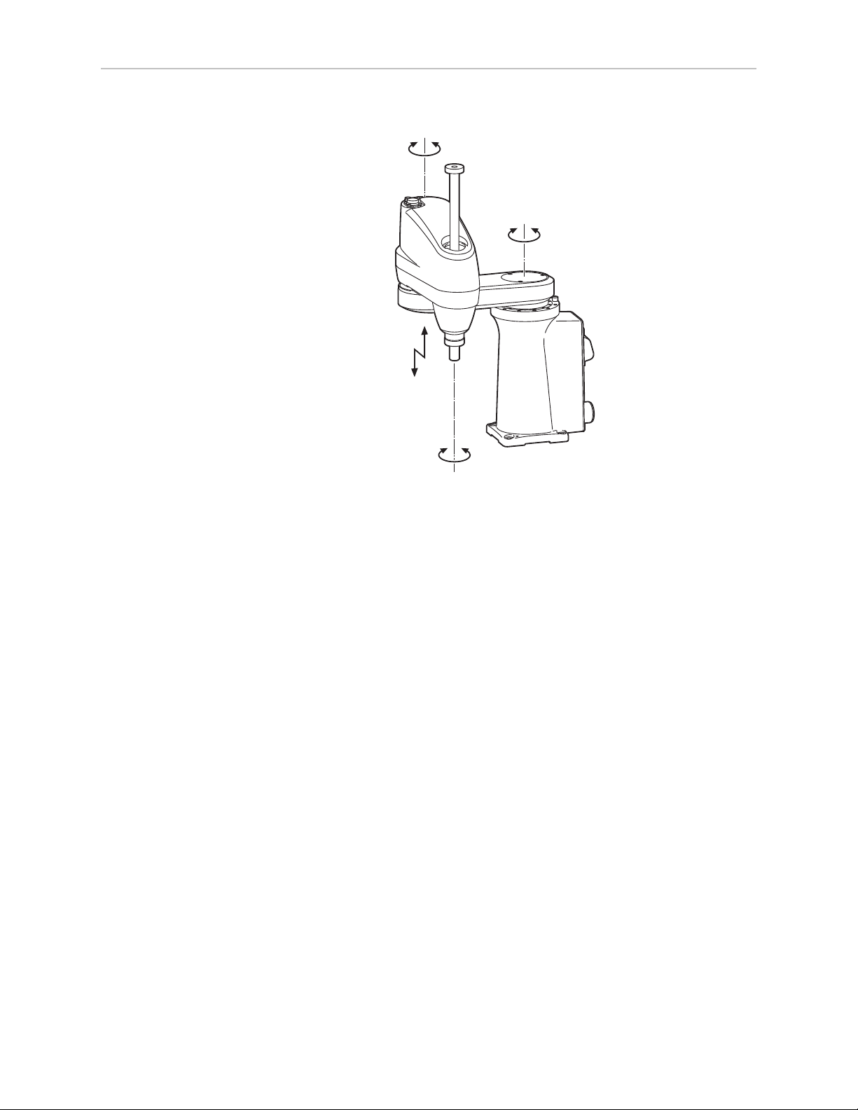
The Adept Cobra s350 robot is a high-performance, four-axis SCARA robot (Selective
Compliance Assembly Robot Arm). Joints 1, 2, and 4 are rotational; Joint 3 is translational. See
Figure 1-2 for a description of the robot joint locations.
The Adept Cobra s350 robots require an Adept MotionBlox-40R™ (either an MB-40R or an
eMB-40R) and an Adept SmartController™ (either CX or EX) motion controller. The robots are
programmed and controlled using the SmartController, running on the Adept SmartServo
distributed motion control platform. Mechanical specifications for the Adept Cobra s350 robots
are provided in Technical Specifications on page 79.
A cleanroom model is also available, the Adept Cobra s350 CR/ESD. See Cleanroom Robots on
page 85 for information.
Chapter 1: Introduction
Figure 1-1. Adept Cobra s350 Robot
Adept Cobra s350 User's Guide, Rev. D
Page 9 of 94
Page 10
Chapter 1: Introduction
2nd axis (J2)
1st axis (J1)
3rd axis (J3)
4th axis (J4)
(-)
(+)
(+)
(+)
(+)
(-)
(-)
(-)
Figure 1-2. Robot Joint Motions
Adept SmartController
The SmartController is the foundation of Adept’s family of high-performance distributed
motion controllers. The SmartController is designed for use with:
l
Adept Cobra™ s-Series robots
l
Adept Quattro™ robots
l
Adept Viper™ s-series robots
l
Adept Python™ linear modules
l
Adept MotionBlox-10™
l
Adept sMI6™ (SmartMotion)
The SmartController supports a conveyor tracking option, as well as other options. There are
two models available: the SmartController CX, which uses the V+ Operating System, and the
SmartController EX, which uses the eV+ Operating System. Both models offer scalability and
support for IEEE 1394-based digital I/O and general motion expansion modules. The IEEE
1394 interface is the backbone of Adept SmartServo, Adept's distributed controls architecture
supporting Adept products. The SmartController also includes Fast Ethernet and DeviceNet.
Adept Cobra s350 User's Guide, Rev. D
Page 10 of 94
Page 11
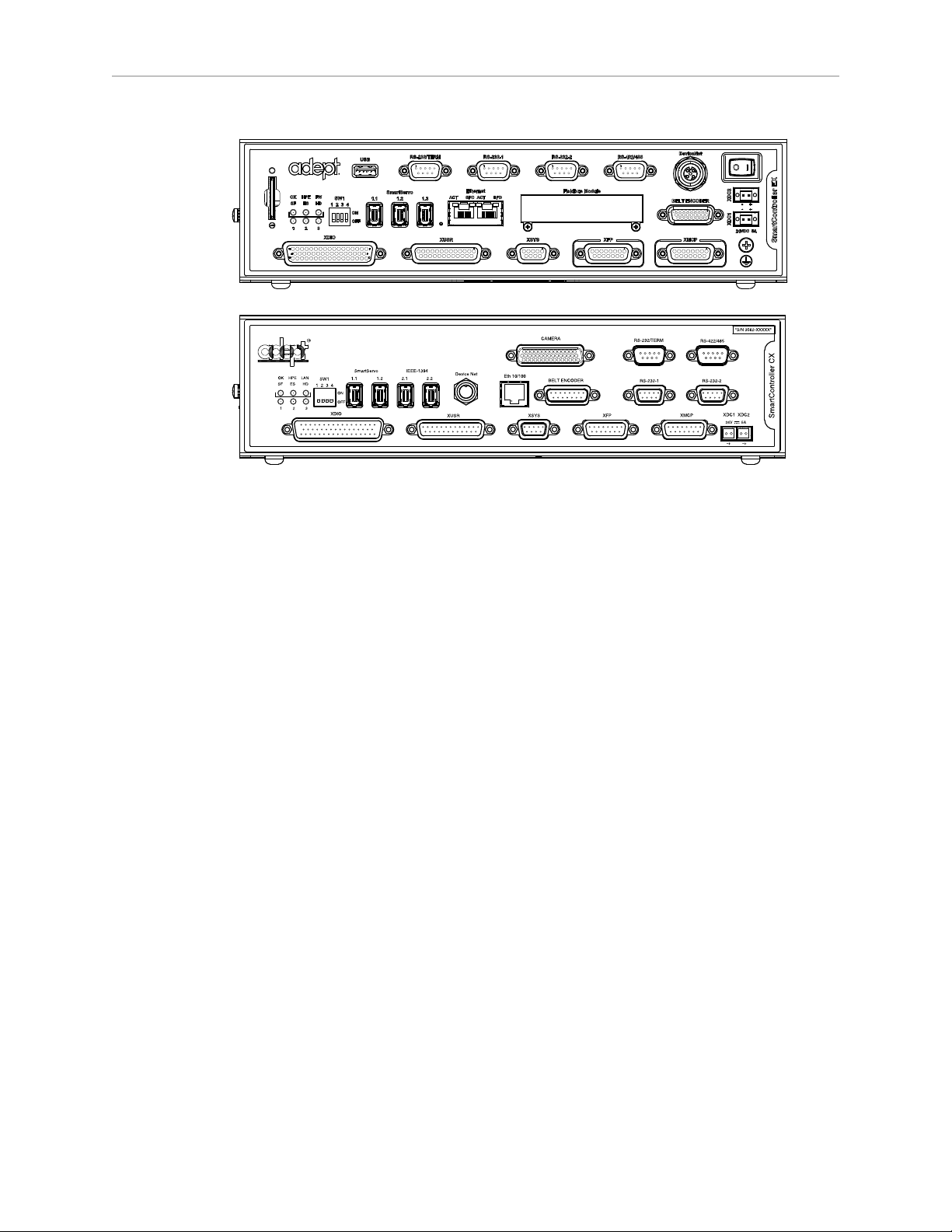
Chapter 1: Introduction
Figure 1-3. Adept SmartController EX and CX Motion Controllers
Adept MotionBlox-40R
The MotionBlox-40R (MB-40R/eMB-40R) Distributed Servo Controller controls the behavior of
the feedback loop between the digital absolute encoders and the high-power motors of the
Adept Cobra s350 robot.
Adept MB-40R/eMB-40R feature:
l
Four AC servo motor amplifiers
l
Emergency stop circuitry
l
High servo rate, to deliver low positional errors and superior path-following
l
Sine wave commutation delivers low cogging torque and improved path-following
l
Digital feed-forward design maximizes efficiency, torque, and velocity
l
Integral temperature sensors and status monitoring for maximum reliability
l
Two-digit diagnostics display for easy troubleshooting
Adept Cobra s350 User's Guide, Rev. D
Page 11 of 94
Page 12
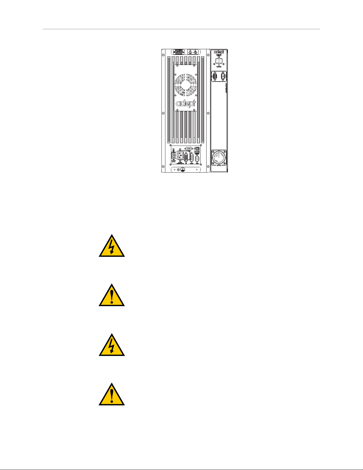
Chapter 1: Introduction
Figure 1-4. MotionBlox-40R (MB-40R shown)
1.2 Dangers, Warnings, Cautions, and Notes
There are six levels of special alert notation used in Adept manuals. In descending order of
importance, they are:
DANGER:This indicates an imminently hazardous
electrical situation which, if not avoided, will result in
death or serious injury.
DANGER:This indicates an imminently hazardous
situation which, if not avoided, will result in death or
serious injury.
WARNING:This indicates a potentially hazardous
electrical situation which, if not avoided, could result in
injury or major damage to the equipment.
WARNING:This indicates a potentially hazardous
situation which, if not avoided, could result in injury or
major damage to the equipment.
Adept Cobra s350 User's Guide, Rev. D
Page 12 of 94
Page 13
Chapter 1: Introduction
CAUTION:This indicates a situation which, if not
avoided, could result in damage to the equipment.
NOTE:Notes provide supplementary information, emphasize a point or procedure,
or give a tip for easier operation.
1.3 Intended Use of the Robot
The Cobra s350 robot is intended for use in parts assembly and material handling for
payloads up to 2.0 kg. See Technical Specifications on page 79 for complete specifications.
Refer to the Adept Robot Safety Guide for details on the intended use of Adept robots.
1.4 Safety Precautions
DANGER:An Adept Cobra s350 robot can cause serious
injury or death, or damage to itself and other equipment,
if the following safety precautions are not observed:
l
All personnel who install, operate, teach, program, or maintain the system must read
this guide, read the Adept Robot Safety Guide, and complete a training course for their
responsibilities in regard to the robot.
l
All personnel who design the robot system must read this guide, read the Adept Robot
Safety Guide, and must comply with all local and national safety regulations for the
location in which the robot is installed.
l
The robot system must not be used for purposes other than described in Section 1.3.
Contact Adept if you are not sure of the suitability for your application.
l
The user is responsible for providing safety barriers around the robot to prevent anyone
from accidentally coming into contact with the robot when it is in motion.
l
Power to the robot and its power supply must be locked out and tagged out before any
maintenance is performed.
1.5 What to Do in an Emergency Situation
Press any E-Stop button (a red push-button on a yellow background/field) and then follow the
internal procedures of your company or organization for an emergency situation. If a fire
occurs, use CO2to extinguish the fire.
1.6 Additional Safety Information
Adept provides other sources for more safety information:
Adept Cobra s350 User's Guide, Rev. D
Page 13 of 94
Page 14

Manufacturer’s Declaration of Conformity (MDOC)
This lists all standards with which each robot complies. See Manufacturer’s Declaration on
page 15.
Adept Robot Safety Guide
The Adept Robot Safety Guide provides detailed information on safety for Adept robots. It also
gives resources for more information on relevant standards.
It ships with each robot manual, and is also available from the Adept Document Library. See
Adept Document Library on page 16.
1.7 Installation Overview
The system installation process is summarized in the following table. Refer also to the system
cable diagram in Figure 3-1.
Task to be Performed Reference Location
Chapter 1: Introduction
Table 1-1. Installation Overview
Mount the robot on a flat, secure mounting surface. Mounting the Robot on page
18.
Install the SmartController, Front Panel, optional
pendant (if present), and Adept ACE software.
Install the IEEE 1394 and XSYS cables between the
MB-40R/eMB-40R and SmartController.
Install the Arm Power/Signal cable between the MB40R/eMB-40R and the robot.
Create a 24 VDC cable and connect it between the MB40R/eMB-40R and the user-supplied 24 VDC power
supply.
Create a 24 VDC cable and connect it between the
SmartController and the user-supplied 24 VDC power
supply.
Create a 200-240 VAC cable and connect it between
the MB-40R/eMB-40R and the facility AC power
source.
Install user-supplied safety barriers in the workcell. Installing User-Supplied
Installing the SmartController
on page 24.
Cable Connections from MB40R/eMB-40R to
SmartController on page 25.
Cable Connections from MB40R/eMB-40R to Robot on
page 26.
Connecting 24 VDC Power to
MB-40R/eMB-40R Servo
Controller on page 26.
Connecting 24 VDC Power to
MB-40R/eMB-40R Servo
Controller on page 26.
Connecting 200-240 VAC
Power to MB-40R/eMB-40R on
page 29.
Safety Equipment on page 34.
Learn about connecting digital I/O through the XIO
connector on the MB-40R/eMB-40R.
Read Chapter 5 to learn about system start-up and
testing operation.
Adept Cobra s350 User's Guide, Rev. D
Page 14 of 94
Connecting Digital I/O to the
System on page 40.
System Operation on page 51.
Page 15

Chapter 1: Introduction
Task to be Performed Reference Location
Read Optional Equipment Installation on page 57 if
you need to install optional equipment, such as endeffectors, user air and electrical lines, and external
equipment.
1.8 Manufacturer’s Declaration
The Manufacturer’s Declaration of Incorporation and Conformity for Adept robot systems can
be found on the Adept website, in the Download Center of the Support section.
http://www.adept.com/support/downloads/file-search
NOTE:The Download Center requires that you are logged in for access. If you are
not logged in, you will be redirected to the Adept website Login page, and then
automatically returned to the Download Center when you have completed the login
process.
1.
From the Download Types drop-down list, select Manufacturer Declarations
2.
From the Product drop-down list, select your Adept robot product category (such as
Adept Cobra Robots, Adept Viper robots, etc.).
3.
Click Begin Search.
The list of available documents is shown in the Search Results area, which opens at the
bottom of the page. You may need to scroll down to see it.
Optional Equipment
Installation on page 57.
4.
Use the Description column to locate the document for your Adept robot, and then click
the corresponding Download ID number to access the Download Details page.
5.
On the Download Details page, click Download to open or save the file.
1.9 How Can I Get Help?
Refer to the How to Get Help Resource Guide (Adept P/N 00961-00700) for details on getting
assistance with your Adept software and hardware. Additionally, you can access information
sources on Adept’s corporate website:
http://www.adept.com
l
For Contact information:
http://www.adept.com/contact/americas
l
For Product Support information: http://www.adept.com/support/service-and-
support/main
l
For user discussions, support, and programming examples:
http://www.adept.com/forum/
Adept Cobra s350 User's Guide, Rev. D
Page 15 of 94
Page 16
Chapter 1: Introduction
Related Manuals
This manual covers the installation, operation, and maintenance of an Adept Cobra s350 robot
system. There are additional manuals that cover programming the system, reconfiguring
installed components, and adding other optional components. See the following table.
Table 1-2. Related Manuals
Manual Title Description
Adept Robot Safety Guide Contains safety information for Adept robots.
Adept SmartController EX
User's Guide
Adept SmartController User's
Guide
Adept T20 Pendant User's
Contains information on the installation and operation of the
Adept SmartController EXand the optional sDIO product.
Contains information on the installation and operation of the
Adept SmartController and the optional sDIO product.
Describes the Adept T20™ pendant.
Guide
Adept T2 Pendant User’s
Describes the Adept T2™ pendant.
Guide
Adept ACE User's Guide Instruction for the use of the Adept ACE software.
Adept IOBlox User's Guide Describes the IO Blox product.
Adept Dual-Robot
Configuration Procedure
Contains cable diagrams and configuration procedures for a
dual-robot system.
Adept Document Library
The Adept Document Library (ADL) contains documentation for Adept products. You can
access the ADL from:
l
the Adept Software disk shipped with your system.
l
the Adept website. Select Document Library from the Adept home page. To go directly to
the Adept Document Library, type the following URL into your browser:
http://www.adept.com/Main/KE/DATA/adept_search.htm
To locate information on a specific topic, use the Document Library search engine on the ADL
main page. To view a list of available product documentation, use the menu links located
above the search field.
Adept Cobra s350 User's Guide, Rev. D
Page 16 of 94
Page 17

Chapter 2: Robot Installation
2.1 Transport and Storage
This equipment must be shipped and stored in a temperature-controlled environment, within
the range –10 to +60 C (14 to 140 F). The recommended humidity range is 5 to 90 percent, noncondensing. It should be shipped and stored in the Adept-supplied packaging, which is
designed to prevent damage from normal shock and vibration. You should protect the package
from excessive shock and vibration.
The robots must always be stored and shipped in an upright position in a clean, dry area that
is free from condensation. Do not lay the crate on its side or any other position: this could
damage the robot.
2.2 Unpacking and Inspecting the Adept Equipment
Before Unpacking
Carefully inspect all shipping crates for evidence of damage during transit. If any damage is
indicated, request that the carrier’s agent be present at the time the container is unpacked.
Upon Unpacking
Before signing the carrier’s delivery sheet, please compare the actual items received (not just
the packing slip) with your equipment purchase order and verify that all items are present and
that the shipment is correct and free of visible damage.
If the items received do not match the packing slip, or are damaged, do not sign the receipt.
Contact Adept as soon as possible.
If the items received do not match your order, please contact Adept immediately.
Inspect each item for external damage as it is removed from its container. If any damage is
evident, contact Adept (see Section 1.9).
Retain all containers and packaging materials. These items may be necessary to settle claims
or, at a later date, to relocate equipment.
2.3 Repacking for Relocation
If the robot or other equipment needs to be relocated, reverse the steps in the installation
procedures that follow. Reuse all original packing containers and materials and follow all
safety notes used for installation. Improper packaging for shipment will void your warranty.
Before unbolting the robot from the mounting surface, fold the outer arm against the Joint 2
hardstops to help centralize the center of gravity. The robot must always be shipped in an
upright orientation. Specify this to the carrier if the robot is to be shipped.
Adept Cobra s350 User's Guide, Rev. D
Page 17 of 94
Page 18
Chapter 2: Robot Installation
Worker B
Worker A
2.4 Environmental andFacility Requirements
The Adept robot system installation must meet the operating environment requirements
shown in the following table.
Table 2-1. Robot System Operating Environment Requirements
Ambient temperature 5 to 40° C (41 to 104° F)
Humidity 5 to 90%, noncondensing
Altitude up to 2000 m (6500 ft.)
Pollution degree 2
Robot protection class IP-20 (NEMA Type 1)
NOTE: See Dimension Drawings on page 79 for robot dimensions.
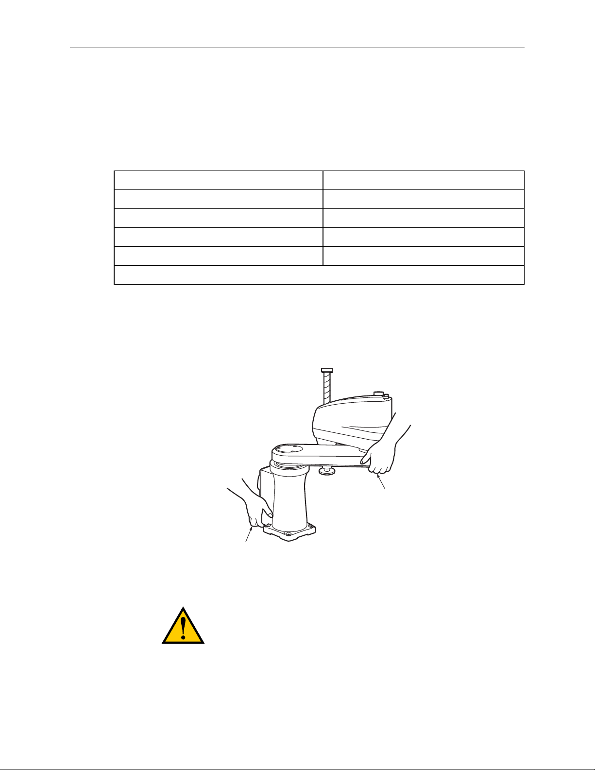
2.5 Mounting the Robot
At least two people should transport and store the packaged equipment (see Figure 2-1).
The robot weighs 20 kg (45 lb) with no options installed.
Figure 2-1. Transporting Robot
CAUTION:Do not hold the robot by parts other than
those shown above.
Adept Cobra s350 User's Guide, Rev. D
Page 18 of 94
Page 19
Chapter 2: Robot Installation
120
120
7
17
R 1500
R 1500
144
(291 for Cabling)
4x Ø 12 Thru
2x Ø 6 H7
+0.012
0
134 ± 0.005
Units are mm
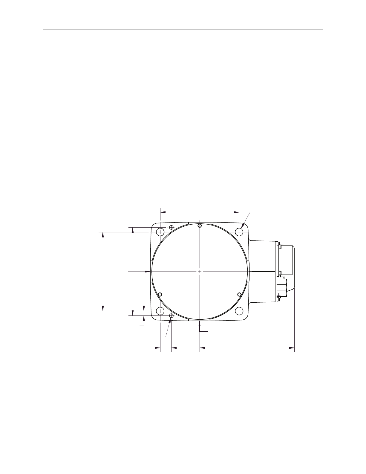
Mounting Surface
The Adept Cobra s350 robot is designed to be mounted on a smooth, flat, level surface. The
mounting surface must be rigid enough to prevent vibration and flexing during robot
operation. Adept recommends a 25 mm (1 in.) thick steel plate mounted to a rigid tube frame.
Excessive vibration or mounting flexure will degrade robot performance. Figure 2-2 shows the
mounting hole pattern for the Adept Cobra s350 robot.
NOTE:On the under-side of the base there are two holes that can be used as
locating points for user-installed dowel pins in the mounting surface. See Figure 2-2
for the hole dimension and location. Using locating pins can improve the ability to
remove and reinstall the robot in the same position.
The Adept Cobra s350 robot can be mounted on a moving platform with proper attention paid
to adequately supporting the robot cabling. The motor/encoder cable connecting the robot to the
MB-40R/eMB-40R is not designed to withstand repeated bending operations and has a
minimum recommended bend radius of 200 mm. The connectors on this cable are not
designed to support any dynamic forces and Adept always advises users to support the
weight of the cable with external supports and tie-downs. Any additional user cabling should
be installed with user-designed cabling supports that do not use these motor/encoder
connectors as attachment points for auxiliary cabling.
Figure 2-2. Mounting Hole Pattern for Robot
Adept Cobra s350 User's Guide, Rev. D
Page 19 of 94
Page 20
Chapter 2: Robot Installation
Bolts
Pallet
Bolts
Tu r n until it comes
into contact with
the mechanical end.
Robot Mounting Procedure
1. Using the dimensions shown in Figure 2-2, drill and tap the mounting surface for four
M10 x 30 mm (or 3/8-16 UNC) machine bolts (user-supplied). Also drill two 6H7
diameter holes for a diamond-shaped dowel pin and an internally-threaded positioning
pin. See Table 2-2 for bolt and torque specifications.
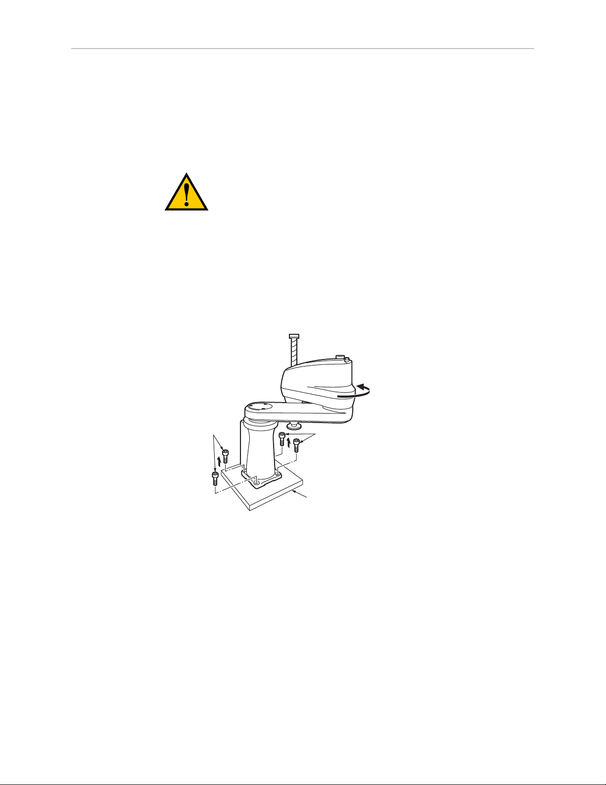
WARNING:Do not attempt to extend the inner or outer
links of the robot until the robot has been secured in
position. Failure to comply could result in the robot
falling and causing either personnel injury or equipment
damage.
2.
Install a diamond-shaped pin into one of the 6H7 diameter holes.
3.
Install an internally-threaded positioning pin into the other 6H7 hole.
4.
Turn the J2 axis until it comes into contact with the mechanical hardstop to keep the
robot in a safe position.
Figure 2-3. Rotate J2 Axis to Safe Position
5.
Remove the four bolts securing the robot base to the pallet. One person should support
the J1 axis arm while another person removes the bolts. Retain these bolts for possible
later relocation of the equipment.
6.
Lift the robot and position it directly over the mounting surface.
7.
Slowly lower the robot while aligning the base and the tapped mounting holes in the
mounting surface.
NOTE:The base casting of the robot is aluminum and can easily be dented if
bumped against a harder surface. Verify that the robot is mounted squarely (will
not rock back and forth) before tightening the mounting bolts.
Adept Cobra s350 User's Guide, Rev. D
Page 20 of 94
Page 21
Chapter 2: Robot Installation
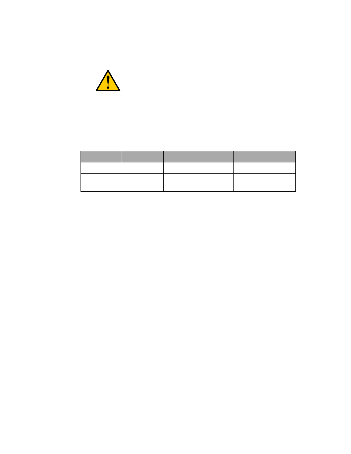
8. Install the user-supplied mounting bolts and washers. Tighten bolts to the torque
specified in Table 2-2.
WARNING:The center of mass of the robot may cause
the robot to fall over if the robot is not secured with the
mounting bolts.
NOTE:Check the tightness of the mounting bolts one week after initial installation,
and then recheck every 6 months. See Periodic Maintenance Schedule on page 67
for periodic maintenance.
Table 2-2. Mounting Bolt Torque Specifications
Standard Size Specification Torque
Metric M10 x 30 mm ISO Property Class 8.8 70 N·m
SAE 3/8-16 UNC SAE J429 Grade 5 or
ASTM A449
52 ft-lbf
Adept Cobra s350 User's Guide, Rev. D
Page 21 of 94
Page 22

Page 23
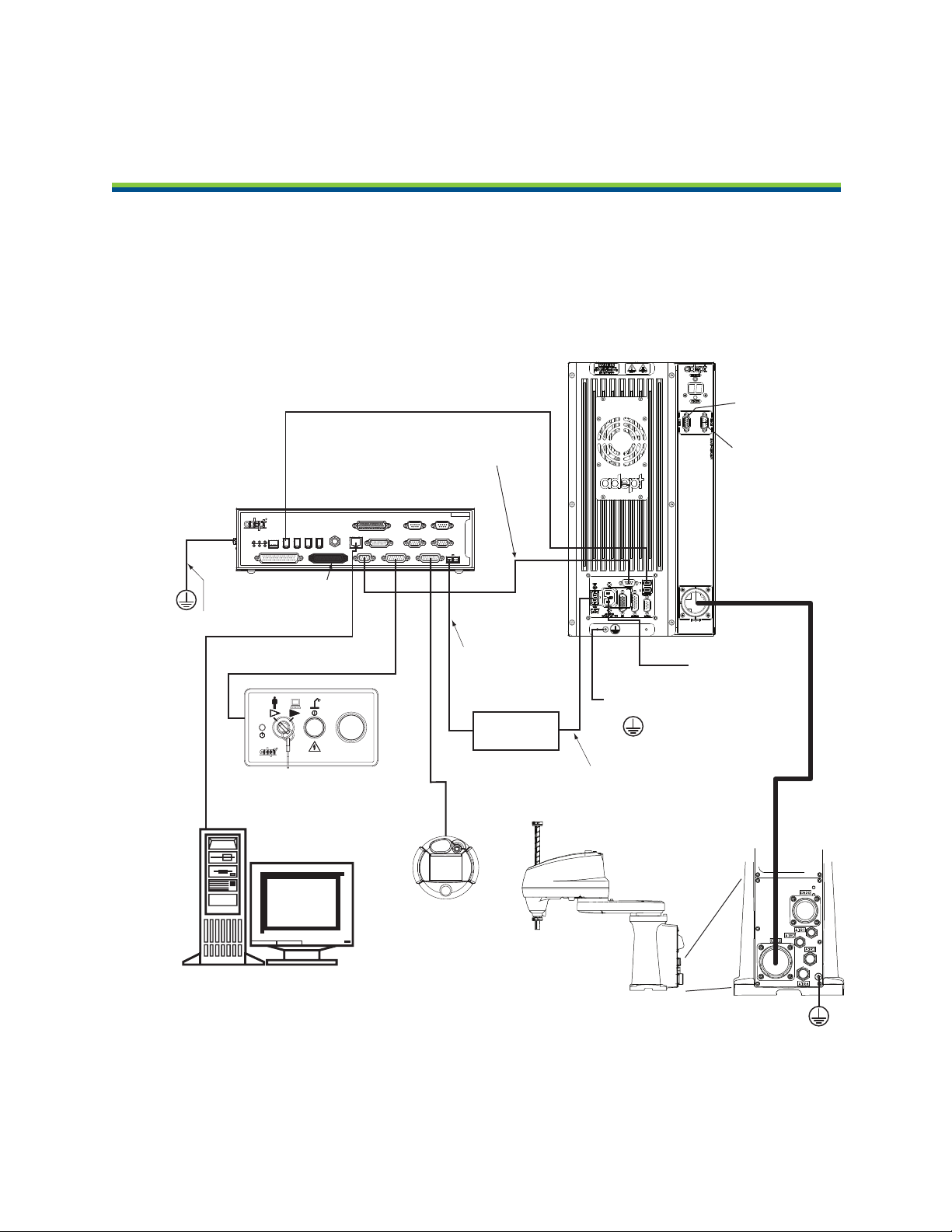
Ethernet to PC
IEEE 1394 Cable
from Controller SmartServo (Port 1.1)
to MB-40R/MB-eMB40R SmartServo
Adept MB-40R/
eMB-40R
Servo Controller
(MB-40R shown)
Adept
SmartController CX
Adept Cobra
s350 Robot
User-Supplied
Power Supply
Controller (XFP) to
Front Panel (XFP)
Front Panel
Pendant
(optional)
XSYS Cable from Controller to
MB-40R/eMB-40R (XSLV/XSYSTEM)
24 VDC Power from
User-Supplied
Power Supply to
Controller (XDC1)
User-supplied desktop or
Laptop PC Running Adept ACE
Terminator
Installed
User-Supplied Ground Wire
User-Supplied
Ground Wire
External Brake
Connector
Arm Power/
Signal Cable
24 VDC Power from
User-Supplied Power
Supply to MB-40R/
eMB-40R (+24 VDC Input)
User-Supplied
200-240 VAC,
single phase
EXPIO
Connector
Note: Objects are
not drawn to scale.
User-Supplied
Ground Wire
STOP
R
R
ON
SmartServo IEEE-1394
1 2 3 4
SF ES HD
SW1
1.1 1.2 2.1 2.2
OK
1 2 3
XDIO
LANHPE
OFF
XSYS
CAMERA
Eth 10/100
XUSR
Device Net
XFP
RS-232/TERM
RS-232-1
XMCP
BELT ENCODER
SmartController CX
-+ -+
RS-422/485
XDC1 XDC2
24V 5A
*S/N 3562-XXXXX*
RS-232-2
Chapter 3: System Cable Installation
3.1 System Cable Diagram
Figure 3-1. System Cable Diagram for Adept Cobra s350 Robots
Adept Cobra s350 User's Guide, Rev. D
Page 23 of 94
Page 24

3.2 Cable List
Cable Description Notes
IEEE 1394 Cable, 4.5 M Standard cable—supplied
Chapter 3: System Cable Installation
Table 3-1. Cables and Parts List
with system
XSYS Cable, 4.5 M
(for MB-40R)
eAIB XSYS Cable, 4.5 M
(for eMB-40R)
eAIB XSLV Adapter Cable, 250 mm
(for eMB-40R with old XSYS cable)
Front Panel Cable Supplied with Front Panel
T1/T2 Pendant Adapter Cable
(for SmartController CX)
T20 Pendant Adapter Cable
(for SmartController EX)
Power Cable Kit - contains 24 VDC and AC
power cables
XIO Breakout Cable, 12 inputs/
8 outputs, 5 meters
Y Cable, for XSYS cable connections to dual
robot (for SmartController)
3.3 Installing the SmartController
Standard cable - supplied with
MB-40R
Standard cable - supplied with
eMB-40R
Standard for MB-40R to eMB40R upgrade.
Supplied with optional T2
pendant
Supplied with optional T20
pendant
Available as option
Available as option—see XIO
Breakout Cable on page 47.
Available as option
Refer to the Adept SmartController User's Guide or Adept SmartController EXUser's Guide for
complete information on installing the Adept SmartController. This list summarizes the main
steps.
1.
Mount the SmartController.
2.
Install the Front Panel. The Front Panel must be outside of the work area, but near the
work area.
3.
Connect the Front Panel to the SmartController.
4.
Connect the optional pendant (if included) to the SmartController.
5.
Connect user-supplied 24 VDC power to the controller. Instructions for creating the
cable, and power specifications, are covered in the Adept SmartController User's Guide or
Adept SmartController EXUser's Guide.
6.
Install a user-supplied ground wire between the SmartController and ground.
7.
Install the Adept ACE PC software on the user-supplied PC (see the following section).
Adept Cobra s350 User's Guide, Rev. D
Page 24 of 94
Page 25

Chapter 3: System Cable Installation
3.4 Installing the Adept ACE Software
The Adept ACE software is installed from the Adept ACE software disk.
1.
Insert the disk into the disk drive of your PC.
If Autoplay is enabled, the Adept software disk menu is displayed. If Autoplay is
disabled, you will need to manually start the disk.
2.
Especially if you are upgrading your Adept ACE software installation: from the Adept
ACE software disk menu, click Read Important Information.
3.
From the Adept ACE software disk menu, select:
Install the Adept ACE Software
The Adept ACE Setup wizard opens.
4.
Follow the online instructions as you step through the installation process.
5.
When the installation is complete, click Finish.
6.
After closing the Adept ACE Setup wizard, click Exit on the disk menu to close the
menu.
NOTE:You will have to restart the PC after installing Adept ACE software.
3.5 Connecting the PC to the SmartController
The Adept SmartController motion controller must be connected to a user-supplied PC or the
Adept SmartVision EX vision processor for setup, control, and programming.
l
Connect an Ethernet crossover cable between the PC and the SmartController motion
controller
or
l
Use two standard Ethernet cables with a network hub or switch in place of the Ethernet
crossover cable.
NOTE:Do not use an Ethernet crossover cable with a network hub or switch.
For more details, refer to the Adept ACE User’s Guide.
3.6 Cable Connections from MB-40R/eMB-40R to SmartController
1.
Locate the IEEE 1394 cable (length 4.5 M) and the XSYS or eAIB XSYS cable (length
4.5M). They are shipped in the cable/accessories box.
2.
Install one end of the IEEE 1394 cable into the SmartServo connector on the
SmartController (port 1.1 for CX, either for EX), and install the other end into a
SmartServo connector on the MB-40R/eMB-40R interface panel, as shown in Figure 3-1.
3.
MB-40R: Install the XSYS cable between the XSYS connector on the SmartController and
the MB-40R XSLV safety interlock connector, and tighten the latching screws.
Adept Cobra s350 User's Guide, Rev. D
Page 25 of 94
Page 26
Chapter 3: System Cable Installation
eMB-40R: Install the eAIBXSYS cable between the XSYS connector on the
SmartController and the eMB-40R XSYSTEM connector, and tighten the latching screws.
If you are upgrading from an MB-40R to an eMB-40R, you can use an eAIB XSLV
adapter cable between your existing XSYS cable and the XSYSTEM connector on the
new eMB-40R.
NOTE:The IEEE 1394 and XSYS/eAIB XSYS cables should be routed away from AC
power and robot interconnect cables.
3.7 Cable Connections from MB-40R/eMB-40R to Robot
Installing the Arm Power/Signal Cable
The cable between the robot and the MB-40R/eMB-40R is called the Arm Power/Signal cable,
as shown in Figure 3-1.
1.
Connect one end of the Arm Power/Signal cable to the CN22 connector on the back plate
of the robot. Tighten the thumb-screw securely.
2.
Connect the other end of the cable to the large, circular connector on the MB-40R/eMB40R. Tighten the screws securely.
WARNING:Verify that all connectors are fully inserted
and screwed down. Failure to do this could cause
unexpected robot motion. Also, a connector could get
pulled out or dislodged unexpectedly.
3.8 Connecting 24 VDC Power to MB-40R/eMB-40R Servo Controller
Specifications for 24 VDC Power
Table 3-2. Specifications for 24 VDC User-Supplied Power Supply
Customer-Supplied Power Supply 24 VDC (± 10%), 150 W (6 A)
(21.6 V<Vin<26.4 V)
Circuit Protection
Power Cabling 1.5 – 1.85 mm² (16-14 AWG)
Shield Termination Cable shield connected to frame ground
1
User-supplied 24 VDC power supply must incorporate overload protection to limit
peak power to less than 300 W, or 8 A in-line fuse protection must be added to the 24
V power source.
1
Output must be less than 300 W peak
or
8 Amp in-line fuse
on power supply and ground point on
MB-40R/eMB-40R, as shown in Figure 3-2.
Adept Cobra s350 User's Guide, Rev. D
Page 26 of 94
Page 27
Chapter 3: System Cable Installation
The power requirements for the user-supplied power supply will vary depending on the
configuration of the robot and connected devices. Adept recommends a 24 V, 6 A power
supply to allow for startup current draw and load from connected user devices, such as digital
I/O loads.
CAUTION:Make sure you select a 24 VDC power
supply that meets the specifications in Table 3-2. Using
an underrated supply can cause system problems and
prevent your equipment from operating correctly. See the
following table for recommended power supplies.
Table 3-3. Recommended 24 VDC Power Supplies
Vendor Name Model Ratings
XP Power JPM160PS24 24 VDC, 6.7 A, 160 W
Mean Well SP-150-24 24 VDC, 6.3 A, 150 W
Astrodyne ASM150-24 24 VDC, 6.66 A, 150 W
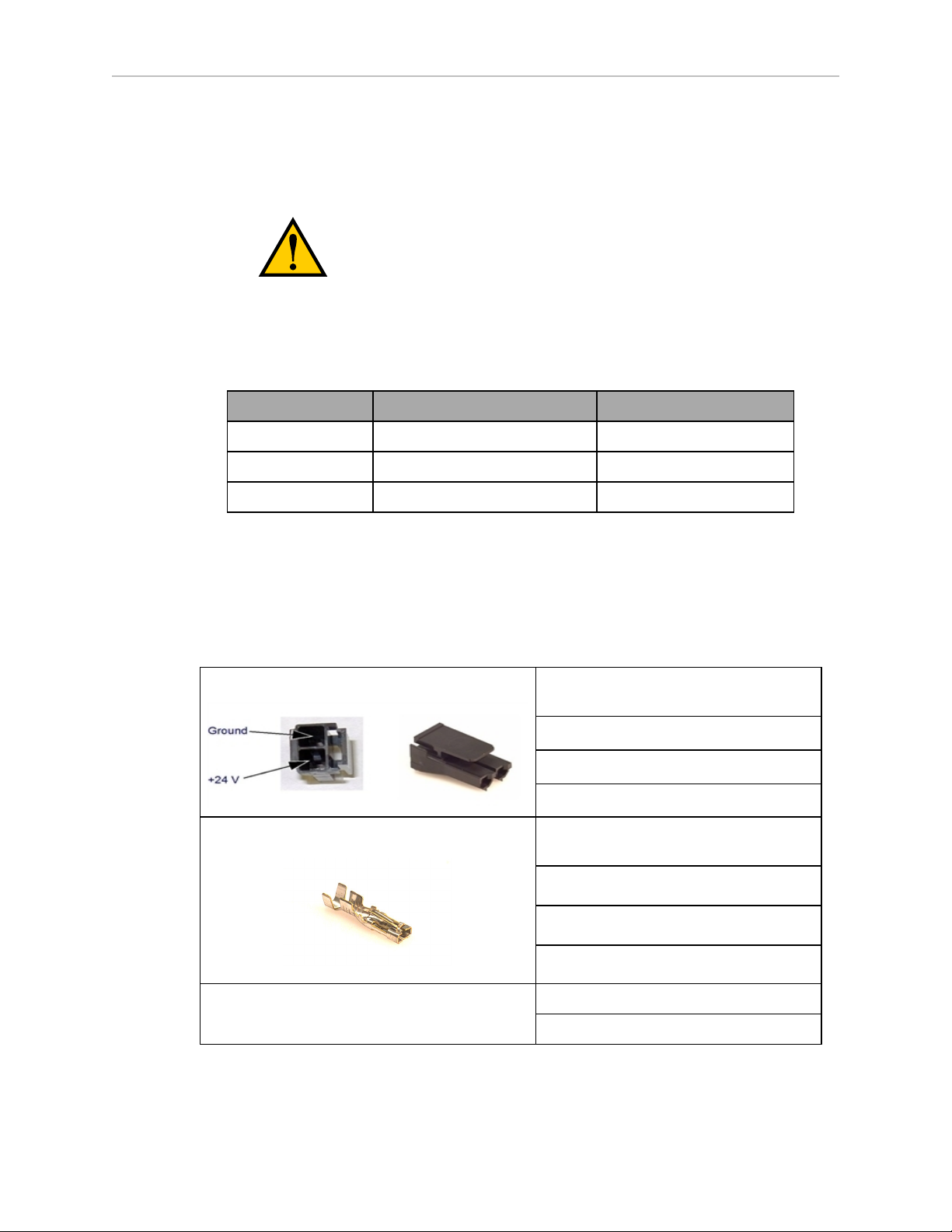
Details for 24 VDC Mating Connector
The 24 VDC mating connector and two pins are supplied with each system. They are shipped
in the cable/accessories box.
Table 3-4. 24 VDC Mating Connector Specs
Connector Details Connector receptacle, 2-position, type:
Molex Saber, 18 A, 2-Pin
Molex P/N 44441-2002
Digi-Key P/N WM18463-ND
Pin Details Molex connector crimp terminal,
female, 14-18 AWG
Molex P/N 43375-0001
Digi-Key P/N WM18493-ND
Recommended crimping tool, Molex Hand
Crimper
Molex P/N 63811-0400
Digi-Key P/N WM9907-ND
Adept Cobra s350 User's Guide, Rev. D
Page 27 of 94
Page 28

Chapter 3: System Cable Installation
NOTE:The 24 VDC cable is not supplied with the system, but is available in the
optional Power Cable kit. See Table 3-1.
Procedure for Creating 24 VDC Cable
1.
Locate the connector and pins from Table 3-4.
2.
Use shielded two-conductor cable with 14-16 AWG wire to create the 24 VDC cable.
Select the wire length to safely reach from the user-supplied 24 VDC power supply to
the MB-40R/eMB-40R base.
You also must create a separate 24 VDC cable for the SmartController. That cable
uses a different style of connector. See the Adept SmartController EX User's Guide or
Adept SmartController User's Guide.
3.
Crimp the pins onto the wires using the crimping tool recommended in Table 3-4.
4.
Insert the pins into the connector. Confirm that the +24 V and Ground wires are in the
correct terminals in the plug.
5.
Install a user-supplied ring lug (for an M3 screw) on the shield at the MB-40R/eMB-40R
end of the cable.
6.
Prepare the opposite end of the cable for connection to the user-supplied 24VDC power
supply, including a terminal to attach the cable shield to frame ground.
Installing the 24 VDC Cable
Do not turn on the 24 VDC power until instructed to do so in the next chapter.
1.
Connect one end of the shielded 24 VDC cable to your user-supplied 24 VDC power
supply. See Figure 3-2. The cable shield should be connected to frame ground on the
power supply. Do not turn on the 24 VDC power until instructed to do so in System
Operation on page 51.
2.
Plug the mating connector end of the 24 VDC cable into the 24 VDC connector on the
interface panel on the back of the MB-40R/eMB-40R. The cable shield should be
connected to the ground point on the interface panel.
Adept Cobra s350 User's Guide, Rev. D
Page 28 of 94
Page 29
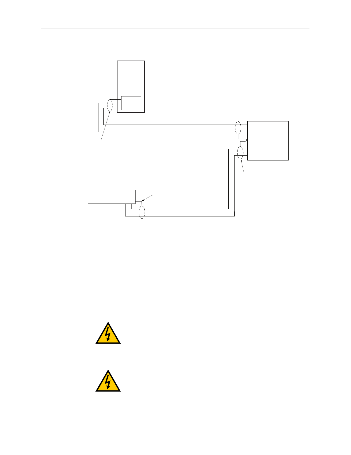
Chapter 3: System Cable Installation
–
+
24V, 8A
Frame Ground
24V, 5A
–
+
User-Supplied
Power Supply
24 VDC
MB-40R/eMB-40R
Servo Controller
User-Supplied Shielded
Power Cable
-
+
Adept SmartController
User-Supplied Shielded
Power Cable
Attach shield from user-supplied
cable to side of controller using
star washer and M3 x 6 screw.
Attach shield from usersupplied cables to frame
ground on power supply.
Attach shield from usersupplied cable to ground
screw on MB-40R Interface
Panel.
–
GND
+
3.9 Connecting 200-240 VAC Power to MB-40R/eMB-40R
Figure 3-2. User-Supplied 24 VDC Cable
NOTE:Adept recommends that DC power be delivered over shielded cables, with
the shield connected to frame ground at the power supply, and to the ground points
shown in the diagram above for the MB-40R/eMB-40R and SmartController. The
length of the wire from the cable shield to the ground points should be less than 50
mm.
WARNING:Ensure compliance with all local and
national safety and electrical codes for the installation
and operation of the robot system.
WARNING:Appropriately-sized Branch Circuit
Protection and Lockout / Tagout Capability must be
provided in accordance with the National Electrical Code
and any local codes.
Adept Cobra s350 User's Guide, Rev. D
Page 29 of 94
Page 30

Chapter 3: System Cable Installation
Specifications for AC Power
Table 3-5. Specifications for 200/240 VAC User-Supplied Power Supply
Auto-Ranging
Nominal
Voltage
Ranges
Minimum
Operating
Voltage
1
Maximum
Operating
Voltage
Frequency/
Phasing
Recommended
External Circuit
Breaker, User-
Supplied
200 V to 240 V 180 V 264 V 50/60 Hz, 1-phase 10 Amps
1
Specifications are established at nominal line voltage. Low line voltage can affect robot
performance.
NOTE:The Adept robot system is intended to be installed as a piece of equipment
in a permanently-installed system.
DANGER:AC power installation must be performed by
a skilled and instructed person—see the Adept Robot
Safety Guide. During installation, unauthorized third
parties must be prevented from turning on power
through the use of fail-safe lockout measures.
Facility Overvoltage Protection
The user must protect the robot from excessive overvoltages and voltage spikes. If the country
of installation requires a CE-certified installation, or compliance with IEC1131-2, the following
information may be helpful: IEC 1131-2 requires that the installation must ensure that
CategoryII overvoltages (i.e., line spikes not directly due to lightning strikes) are not exceeded.
Transient overvoltages at the point of connection to the power source shall be controlled not to
exceed overvoltage CategoryII, i.e., not higher than the impulse voltage corresponding to the
rated voltage for the basic insulation. The user-supplied equipment or transient suppressor
shall be capable of absorbing the energy in the transient.
In the industrial environment, nonperiodic over-voltage peaks may appear on mains power
supply lines as a result of power interruptions to high-energy equipment (such as a blown fuse
on one branch in a 3-phase system). This will cause high-current pulses at relatively low
voltage levels. The user shall take the necessary steps to prevent damage to the robot system
(such as by interposing a transformer). See IEC 1131-4 for additional information.
Adept Cobra s350 User's Guide, Rev. D
Page 30 of 94
Page 31

AC Power Diagrams
EENNL
L
F1 10A
Note: F1 is user-supplied, must be slow-blow.
1Ø
200–240 VAC
20 A
MB-40R/eMB-40R
1Ø 200-240 VAC
User-Supplied
AC Power Cable
L =Line
N = Neutral
E = Earth Ground
EENL3L
L1
L2
F5 10 A
F4 10 A
User-Supplied
AC Power Cable
Note: F4 and F5 are user-supplied, must be slow-blow.
3Ø
200–240 VAC
L = Line 1
N = Line 2
E = Earth Ground
200–240 VAC
MB-40R/eMB-40R
1Ø 200-240 VAC
Figure 3-3. Typical AC Power Installation with Single-Phase Supply
Chapter 3: System Cable Installation
Figure 3-4. Single-Phase Load across L1 and L2 of a Three-Phase Supply
Details for AC Mating Connector
The AC mating connector is supplied with each system. It is shipped in the cable/accessories
box. The supplied plug is internally labeled for the AC power connections (L, E, N).
Table 3-6. AC Mating Connector Details
AC Connector details AC in-line power plug,
straight, female, screw
Adept Cobra s350 User's Guide, Rev. D
Page 31 of 94
terminal, 10 A, 250 VAC
Qualtek P/N 709-00/00
Digi-Key P/N Q217-ND
Page 32

Chapter 3: System Cable Installation
NOTE:The AC power cable is not supplied with the system, but is available in the
optional Power Cable kit. See Table 3-1.
Procedure for Creating 200-240 VAC Cable
1.
Locate the AC mating connector shown in Table 3-6.
2.
Open the connector by unscrewing the screw on the shell and removing the cover.
3.
Loosen the two screws on the cable clamp. See Figure 3-5 for details.
4.
Use 18 AWG wire to create the AC power cable. Select the wire length to safely reach
from the user-supplied AC power source to the MB-40R/eMB-40R base.
5.
Strip 18 to 24 mm of insulation from each of the three wires.
6.
Insert the wires into the connector through the removable bushing.
7.
Connect each wire to the correct terminal screw, and tighten the screw firmly.
8.
Tighten the screws on the cable clamp.
9.
Replace the cover and tighten the screw to seal the connector.
10.
Prepare the opposite end of the cable for connection to the facility AC power source.
Figure 3-5. AC Power Mating Connector
Installing AC Power Cable to MB-40R/eMB-40R
1.
Connect the unterminated end of the AC power cable to your facility AC power source.
See Figure 3-3 and Figure 3-4 for details. Do not turn on AC power at this time.
2.
Plug the AC connector into the AC power connector on the interface panel on the MB40R/eMB-40R.
3.
Secure the AC connector with the locking latch.
Adept Cobra s350 User's Guide, Rev. D
Page 32 of 94
Page 33

Chapter 3: System Cable Installation
Ground Poi nt
3.10 Grounding the Adept Robot System
Proper grounding is essential for safe and reliable robot operation. Follow these
recommendations to properly ground your robot system.
Ground Point on Robot Base
The user can install a ground wire at the robot base to ground the robot. The ground point is
shown in Figure 3-6. The user is responsible for supplying the ground wire to connect to earth
ground.
Figure 3-6. Ground Point on Robot Base
Ground Point on MotionBlox-40R
The user can install a ground wire at the MB-40R/eMB-40R chassis. Use the hole below the
MB-40R/eMB-40R interface panel - see the following figure. The user should provide a ground
wire and use the provided M3 screw and external tooth lock washer to connect to earth
ground. Make sure to tighten the screw on the ground wire to create a proper ground
connection. Two tapped holes are provided to attach optional user-supplied strain relief.
Figure 3-7. Earth Ground Location, MB-40R shown
Adept Cobra s350 User's Guide, Rev. D
Page 33 of 94
Page 34

Chapter 3: System Cable Installation
Robot-Mounted Equipment Grounding
The Adept Cobra s350 Joint 3 quill and tool flange are not reliably grounded to the robot base.
If hazardous voltages are present at any user-supplied robot-mounted equipment or tooling,
you must install a ground connection from that equipment/tooling to the ground point on the
robot base. Hazardous voltages can be considered anything in excess of 30 VAC (42.4 VAC
peak) or 60VDC.
Also, see Figure 8-3 for the grounding point on the tool flange.
DANGER:Failing to ground robot-mounted equipment
or tooling that uses hazardous voltages could lead to
injury or death of a person touching the end-effector
when an electrical fault condition exists.
3.11 Installing User-Supplied Safety Equipment
The user is responsible for installing safety barriers to protect personnel from coming in
contact with the robot unintentionally. Depending on the design of the workcell, safety gates,
light curtains, and emergency stop devices can be used to create a safe environment. Read the
Adept Robot Safety Guide for a discussion of safety issues.
Refer to the Adept SmartController User's Guide or Adept SmartController EXUser's Guide for
information on connecting safety equipment into the system through the XUSR connector on
the SmartController. There is a detailed section on Emergency Stop circuits and diagrams on
recommended E-Stop configurations.
Adept Cobra s350 User's Guide, Rev. D
Page 34 of 94
Page 35

4.1 Introduction
DC
IN
24V
GND
AC
200 240V
Ø
1
XBELTIO
XIO
Servo
ENETENET
XSYSTEM
Robot
Interface
Panel
Robot
Connector
(for Arm
Power/Signal
Cable from
Robot)
The Adept MotionBlox-40R (MB-40R/eMB-40R) is a distributed servo controller and amplifier.
It has a dedicated digital signal processor to communicate, coordinate, and execute servo
commands.
The MB-40R/eMB-40R consists of:
l
a distributed servo amplifier
l
a RISC processor for servo loop control
l
a node on the IEEE 1394 network
l
a power controller that uses single-phase AC power, 200-240 Volts
l
a status panel with a 2-digit alpha-numeric display to indicate operating status and
fault codes
Chapter 4: MotionBlox-40R
Figure 4-1. MB-40R, eMB-40R Front View
Adept Cobra s350 User's Guide, Rev. D
Page 35 of 94
Page 36

Chapter 4: MotionBlox-40R
4.2 Description of Connectors on MB-40R/eMB-40R Interface Panel
Figure 4-2. eMB-40R Interface Panel
Figure 4-3. MB-40R Interface Panel
See the following table for descriptions of the connectors shown in the previous figures.
Adept Cobra s350 User's Guide, Rev. D
Page 36 of 94
Page 37

Chapter 4: MotionBlox-40R
Table 4-1. Connectors on the MB-40R/eMB-40R Interface Panels
24 VDC For connecting user-supplied 24 VDC power. The mating connector is
provided.
Ground
Point
200/240
VAC
SmartServo For connecting the IEEE 1394 cable from the controller.
XIO For user I/O signals for peripheral devices. This connector provides 8 outputs
XSYSTEM eMB-40R only, includes the functions of the XPANEL and XSLV on the MB-
ENET eMB-40R only. Reserved for future use.
XBELTIO eMB-40R only. Adds two belt encoders, EXPIO at the back of the robot (not
XSLV MB-40R only, for connecting the supplied XSYS cable from the controller
For connecting cable shield from user-supplied 24 VDC cable.
For connecting 200-240 VAC, single-phase, input power. The mating
connector is provided.
(SmartServo 1.1) to a SmartServo/Servo on the MB-40R/eMB-40R.
and 12 inputs. See Connecting Digital I/O to the System on page 40 for
connector pin allocations for inputs and outputs. That section also contains
details on how to access these I/O signals. (DB-26, high density, female)
60R. Connects to the controller XSYS connector.
This requires either an eAIB XSLV Adapter cable to connect to the XSYS cable,
or an eAIB XSYS cable (HDB44-to-DB9, male), which replaces the XSYS cable.
available on an MB-40R), and an RS-232 interface, which is reserved for
future use.
XSYS connector. (DB-9, female).
XPANEL MB-40R only. Not used (DB-26, high density, male).
RS-232 MB-40R only. Reserved for future use (DB-9, male).
4.3 MB-40R/eMB-40R Operation
Status LED on MB-40R/eMB-40R
The Status LED indicator is located on the top of the MB-40R/eMB-40R. See the following
figure. This is a bi-color, red and green LED. The color and blinking pattern indicates the
status of the robot. See the following table.
Adept Cobra s350 User's Guide, Rev. D
Page 37 of 94
Page 38

Chapter 4: MotionBlox-40R
Figure 4-4. Controls and Indicators on MB-40R
Table 4-2. Status LED Definition
LED Status Description
Off 24 VDC not present
Green, Slow Blink High Power Disabled
Green, Fast Blink High Power Enabled
Green/Red Blink Selected Configuration Node
Red, Fast Blink Fault, see Status Panel Display
Solid Green or Red Initialization or Robot Fault
Status Panel
The status panel, shown in Figure 4-4, displays alpha-numeric codes that indicate the
operating status of the MB-40R/eMB-40R. The following table gives definitions of the fault
codes. These codes provide details for quickly isolating problems during troubleshooting.
Adept Cobra s350 User's Guide, Rev. D
Page 38 of 94
Page 39

Chapter 4: MotionBlox-40R
Table 4-3. Status Panel Codes
LED Status Code LED Status Code
OK No Fault H# High Temp Encoder (Joint #)
ON High Power ON Status hV High Voltage Bus Fault
MA Manual Mode I# Initialization Stage (Step #)
24 24 V Supply Fault M# Motor Stalled (Joint #)
A# Amp Fault (Joint #) NV Non-Volatile Memory
B# IO Blox Fault (Address #) P# Power System Fault (Code #)
BA Backup Battery Low Voltage PR Processor Overloaded
AC AC Power Fault RC RSC Fault
D# Duty Cycle Exceeded (Joint #) S# Safety System Fault (Code #)
E# Encoder Fault (Joint #) SE E-Stop Delay Fault
ES E-Stop SW Watchdog Timeout
F# External Sensor Stop T# Safety System Fault
(Code 10 + #)
FM Firmware Mismatch TR Teach Restrict Fault
FW 1394 Fault V# Hard Envelope Error (Joint #)
h# High Temp Amp (Joint #)
NOTE:Due to the nature of the Cobra s350 bus line encoder wiring, a single
encoder wiring error may result in multiple channels of displayed encoder errors.
Reference the lowest encoder number displayed.
For more information on status codes, go to the Adept Document Library on the Adept website,
and in the Procedures, FAQs, and Troubleshooting section, look for the Adept Status Code
Summary document.
Brake Release Button on MB-40R/eMB-40R
The Brake Release button is located at the top right of the MB-40R/eMB-40R, as shown in
Figure 4-4. Under some circumstances you may want to manually position Joints 3 and 4
without turning on high power. You can use the Brake Release button for this purpose.
When 24 V power is enabled, pressing this button releases the brake, which allows movement
of Joints 3 and 4. An additional Brake Release button is provided on the robot. For details, see
Brake Release Button on page 51.
NOTE:If this button is pressed while high power is on, high power will
automatically shut down.
Adept Cobra s350 User's Guide, Rev. D
Page 39 of 94
Page 40

Chapter 4: MotionBlox-40R
Pin 1
Pin 5
Pin 6
Pin 9
Brake Release Connector
The 9-pin Brake Release connector provides low-active input signals to manually release the
brakes on Joint 3 and Joint 4. This can be used as an alternative to the Brake Release button.
The digital inputs on this connector meet the same input level requirements as the XIO inputs.
See Table 4-8 for details.
Table 4-4. Brake Release Connector Pinouts
Pin # Description Pin Location
1 Not connected
2 Not connected
3 Release3_N
4 Not connected
5 Not connected
6 Not connected
7 GND
DB-9 Female
Brake Connector
8 Not connected
9 24V
Mating Connector: D-Subminiature 9-Pin Male
4.4 Connecting Digital I/O to the System
You can connect digital I/O to the system in several different ways. See the following table and
figure.
Table 4-5. Digital I/O Connection Options
Product I/O Capacity For more details
XIO Connector on MB40R/eMB-40R
XDIO Connector on
SmartController
Optional sDIO Module,
connects to controller
Optional IO Blox Devices,
connect to EXPIO
connector on the MB40R/eMB-40R
12 inputs
8 outputs
12 inputs
8 outputs
32 inputs, 32 outputs per
module; up to four sDIO devices
per system
8 inputs, 8 outputs per device; up
to four IO Blox devices per
system
Using Digital I/O on MB40R/eMB-40R XIO Connector
on page 42
Adept SmartController EX
User’s Guide or Adept
SmartController User’s Guide
Adept IO Blox User’s Guide
Adept Cobra s350 User's Guide, Rev. D
Page 40 of 94
Page 41

Chapter 4: MotionBlox-40R
Figure 4-5. Connecting Digital I/O to the System
(MB-40R and SmartController CX shown)
Table 4-6. Default Digital I/O Signal Configuration, Single Robot System
Location Type Signal Range
SmartController XDIO connector Inputs 1001 - 1012
Outputs 0001 - 0008
sDIO Module 1 Inputs 1033 - 1064
Outputs 0033 - 0064
sDIO Module 2 Inputs 1065 - 1096
Outputs 0065 - 0096
MB-40R/eMB-40R 1 XIO connector Inputs 1097 - 1108
Outputs 0097 - 0104
Adept Cobra s350 User's Guide, Rev. D
Page 41 of 94
Page 42

Chapter 4: MotionBlox-40R
Location Type Signal Range
IO Blox 1 Inputs 1113 - 1120
Outputs 0105 - 0112
IO Blox 2 Inputs 1121 - 1128
Outputs 0113 - 0120
IO Blox 3 Inputs 1129 - 1136
Outputs 0121 - 0128
IO Blox 4 Inputs 1137 - 1144
Outputs 0129 - 0136
4.5 Using Digital I/O on MB-40R/eMB-40R XIO Connector
The XIO connector on the MB-40R/eMB-40R interface panel offers access to digital I/O, 12
inputs and 8 outputs. These signals can be used by V+/eV+ to perform various functions in the
workcell. See the following table for the XIO signal designations.
l
12 Inputs, signals 1097 to 1108
l
8 Outputs, signals 0097 to 0104
Adept Cobra s350 User's Guide, Rev. D
Page 42 of 94
Page 43

Chapter 4: MotionBlox-40R
Pin 1
Pin 9
Pin 10
Pin 18
Pin 26
Pin 19
Table 4-7. XIO Signal Designations
Pin
No. Designation
Signal
Bank
V+/eV+
Signal
Number
1 GND
2 24 VDC
3 Common 1 1
4 Input 1.1 1 1097
5 Input 2.1 1 1098
6 Input 3.1 1 1099
7 Input 4.1 1 1100
8 Input 5.1 1 1101
9 Input 6.1 1 1102
10 GND
11 24 VDC
12 Common 2 2
13 Input 1.2 2 1103
14 Input 2.2 2 1104
15 Input 3.2 2 1105
16 Input 4.2 2 1106
Pin Locations
XIO 26-pin female
connector on
MB-40R/eMB-40R
Interface Panel
17 Input 5.2 2 1107
18 Input 6.2 2 1108
19 Output 1 0097
20 Output 2 0098
21 Output 3 0099
22 Output 4 0100
23 Output 5 0101
24 Output 6 0102
25 Output 7 0103
26 Output 8 0104
Adept Cobra s350 User's Guide, Rev. D
Page 43 of 94
Page 44

Chapter 4: MotionBlox-40R
Optional I/O Products
These optional products are also available for use with digital I/O:
l
XIO Breakout Cable, 5 meters long, with flying leads on user’s end (see XIO Breakout
Cable on page 47). It is not compatible with the XIO Termination Block mentioned
below.
l
XIO Termination Block, with terminals for user wiring, plus input and output status
LEDs. Connects to the XIO connector with 6-foot cable. See the Adept XIO Termination
Block Installation Guide for details.
XIO Input Signals
The 12 input channels are arranged in two banks of six. Each bank is electrically isolated from
the other bank and is optically isolated from the MB-40R/eMB-40R ground. The six inputs
within each bank share a common source/sink line.
The inputs are accessed through direct connection to the XIO connector (see the following
table), or through the optional XIO Termination Block. See the documentation supplied with
the Termination Block for details.
The XIO inputs cannot be used for REACTI programming, high-speed interrupts, or vision
triggers. Refer to the V+/eV+ user guides in the Adept Document Library (ADL) on the Adept
website. For more details on the ADL, see Adept Document Library on page 16.
XIO Input Specifications
Parameter Value
Operational voltage range 0 to 30 VDC
OFF state voltage range 0 to 3 VDC
ON state voltage range 10 to 30 VDC
Typical threshold voltage Vin= 8 VDC
Operational current range 0 to 7.5 mA
OFF state current range 0 to 0.5 mA
ON state current range 2.5 to 6 mA
Typical threshold current 2.0 mA
Impedance (Vin/I
Current at Vin= +24 VDC I
Turn on response time (hardware)
Software scan rate/response time
Table 4-8. XIO Input Specifications
) 3.9 K Ω minimum
in
≤ 6 mA
in
5 µsec maximum
16 ms scan cycle/
32 ms max response time
Turn off response time (hardware)
Software scan rate/response time
Adept Cobra s350 User's Guide, Rev. D
Page 44 of 94
5 µsec maximum
16 ms scan cycle/
32 ms max response time
Page 45

NOTE: The input current specifications are provided for reference. Voltage sources
Adept-Supplied Equipment
User-Supplied Equipment
Signal 1097
Part Present Sensor
4
Signal 1098
Feeder Empty Sensor
5
Signal 1099
Part Jammed Sensor
6
Signal 1100
Sealant Ready Sensor
7
Signal 1101
8
Signal 1102
+24V
GND
9
Bank 1
Common
Bank 2
Common
3
2
1
Signal 1103
13
Signal 1104
14
Signal 1105
15
Signal 1106
16
Signal 1107
17
Signal 1108
18
12
GND
10
+24V
11
Wiring
Terminal
Block
Typical User
Input Signals
Note: all Input signals
can be used for either
sinking or sourcing
configurations.
Bank 1 configured for
Sinking (NPN) Inputs
Bank 2 configured for
Sourcing (PNP) Inputs
Input Bank 2 Input Bank 1
XIO Connector – 26-Pin Female D-Sub
(equivalent circuit)
are typically used to drive the inputs.
Typical Input Wiring Example
Chapter 4: MotionBlox-40R
Figure 4-6. Typical User Wiring for XIO Input Signals
NOTE:The off-state current range exceeds the leakage current of XIO outputs. This
guarantees that the inputs will not be turned on by the leakage current from the
outputs. This is useful in situations where the outputs are looped-back to the inputs
for monitoring purposes.
Adept Cobra s350 User's Guide, Rev. D
Page 45 of 94
Page 46

Chapter 4: MotionBlox-40R
XIO Output Signals
The eight digital outputs share a common, high-side (sourcing) driver IC. The driver is
designed to supply any kind of load with one side connected to ground. It is designed for a
range of user-provided voltages from 10 to 24 VDC, and each channel is capable of up to 0.7 A
of current. This driver has overtemperature protection, current limiting, and shorted-load
protection. In the event of an output short or other overcurrent situation, the affected output of
the driver IC turns off and back on automatically to reduce the temperature of the IC. The
driver draws power from the primary 24 VDC input to the robot through a self-resetting
polyfuse.
The outputs are accessed through direct connection to the XIO connector (see Table 4-7), or
through the optional XIO Termination Block. See the documentation supplied with the
Termination Block for details.
XIO Output Specifications
Table 4-9. XIO Output Circuit Specifications
Parameter Value
Power supply voltage range See Table 3-2.
Operational current range, per
channel
Total Current Limitation, all
channels on.
On-state resistance (I
= 0.5 A) Ron≤ 0.32 Ω @ 85° C
out
Output leakage current I
I
≤ 700 mA
out
I
≤ 1.0 A @ 50° C ambient
total
I
≤ 1.5 A @ 25° C ambient
total
≤ 25 µA
out
Turn-on response time 125 µsec max., 80 µsec typical
(hardware only)
Turn-off response time 60 µsec. max., 28 µsec typical
(hardware only)
Output voltage at inductive load
turnoff (I
= 0.5 A, Load = 1 mH)
out
DC short circuit current limit 0.7 A ≤ I
Peak short circuit current I
(+V - 65) ≤ V
LIM
≤ 4 A
ovpk
demag
≤ 2.5 A
≤ (+V - 45)
Adept Cobra s350 User's Guide, Rev. D
Page 46 of 94
Page 47

Chapter 4: MotionBlox-40R
M
Adept-Supplied Equipment User-Supplied Equipment
Outputs 1-8
Typical User Loads
XIO Connector – 26-Pin Female D-Sub
+24 VDC
19
Signal 0097
20
Signal 0098
21
Signal 0099
22
Signal 0100
23
Signal 0101
24
Signal 0102
25
Signal 0103
26
Signal 0104
GND
GND
Load
1
Customer
AC Power
Supply
10
M
Load
Load
L
N
(equivalent
circuit)
Wiring
Terminal
Block
Typical Output Wiring Example
Figure 4-7. Typical User Wiring for XIO Output Signals
XIO Breakout Cable
The XIO Breakout cable is available as an option—see the following figure. This cable connects
to the XIO connector on the MB-40R/eMB-40R, and provides flying leads on the user’s end, for
connecting input and output signals in the workcell. The cable length is 5 M (16.4 ft).
See the following table for the cable wire chart.
NOTE:This cable is not compatible with the XIO Termination Block.
Figure 4-8. Optional XIO Breakout Cable
Adept Cobra s350 User's Guide, Rev. D
Page 47 of 94
Page 48

Chapter 4: MotionBlox-40R
Pin 9
Pin 1
Pin 18
Pin 10
Pin 19
Pin 26
Table 4-10. XIO Breakout Cable Wire Chart
Signal
Pin No.
Designation Wire Color Pin Locations
1 GND White
2 24 VDC White/Black
3 Common 1 Red
4 Input 1.1 Red/Black
5 Input 2.1 Yellow
6 Input 3.1 Yellow/Black
7 Input 4.1 Green
8 Input 5.1 Green/Black
9 Input 6.1 Blue
10 GND Blue/White
11 24 VDC Brown
12 Common 2 Brown/White
13 Input 1.2 Orange
14 Input 2.2 Orange/Black
15 Input 3.2 Gray
16 Input 4.2 Gray/Black
17 Input 5.2 Violet
18 Input 6.2 Violet/White
19 Output 1 Pink
20 Output 2 Pink/Black
21 Output 3 Light Blue
22 Output 4 Light Blue/Black
23 Output 5 Light Green
24 Output 6 Light Green/Black
25 Output 7 White/Red
26-pin male
connector on XIO
Breakout Cable
26 Output 8 White/Blue
Shell Shield
Adept Cobra s350 User's Guide, Rev. D
Page 48 of 94
Page 49

Chapter 4: MotionBlox-40R
0
425.5
20.6
204.2
404.9
51.6
331.7
9.8
0
228.6
67.3
222.3
106.7
182.9
170.2
6X, SHCS,M4 X 6
A
B
0
47.6
377.8
0
7.6
45.7
129.54
C
0
32.7
197.8
0
7.6
45.7
C
0
32.7
197.8
0
7.6
45.7
C
0
47.6
377.8
0
7.6
45.7
SPCD AS SHOWN, 20X
M4 X 7 mm DP BLIND
C
0
32.7
197.8
0
47.6
377.8
B
Note: 112 mm clearance required
in front of unit to remove AIB from
box enclosure.
Units in mm
4.6 MB-40R/eMB-40R Dimensions
See the following figure for dimensions of MB-40R/eMB-40R chassis and mounting holes.
Figure 4-9. MB-40R/eMB-40R Mounting Dimensions
Adept Cobra s350 User's Guide, Rev. D
Page 49 of 94
Page 50

Chapter 4: MotionBlox-40R
4.7 Mounting the MB-40R/eMB-40R
The MB-40R/eMB-40R can be panel-mounted.
NOTE: The mounting of the MB-40R/eMB-40R and all terminations at the MB40R/eMB-40R must be performed in accordance with all local and national
standards.
Panel-Mounting the MB-40R/eMB-40R
To panel-mount the MB-40R/eMB-40R, install two brackets on each side at the rear of the unit
(see the following figure for the bracket dimensions). Use the screws from the accessories kit.
Figure 4-10. Panel-Mounting the MB-40R/eMB-40R
Adept Cobra s350 User's Guide, Rev. D
Page 50 of 94
Page 51

5.1 Status Panel Codes
The status panel display on the MB-40R/eMB-40R displays alpha-numeric codes that indicate
the operating status of the robot, including detailed fault codes. The chapter on MotionBlox40R gives definitions of the fault codes. These codes provide details for quickly isolating
problems during troubleshooting. For more details, see MotionBlox-40R on page 35.
For more information on status codes, go to the Adept Document Library on the Adept web
site, and in the Procedures, FAQs, and Troubleshooting section, look for the Adept Status Code
Summary document.
5.2 Brakes
The robot has a braking system that decelerates the robot in an emergency condition, such as
when the emergency stop circuit is open or a robot joint passes its softstop.
The braking system will not prevent you from moving the robot manually once the robot has
stopped (and High Power has been removed).
In addition, Joints 3 and 4 have electromechanical brakes. The brakes are released when high
power is enabled. When High Power is turned off, the brakes engage and hold the positions of
Joints 3 and 4. There is a Brake Release button for Joints 3 and 4 on the MB-40R/eMB-40R and
a Brake Release button on the robot itself. See Brake Release Button on MB-40R/eMB-40R on
page 39 for information on the Brake Release button on the MB-40R/eMB-40R.
Chapter 5: System Operation
Brake Release Button
Under some circumstances you may want to manually position Joint 3 or Joint 4. For such
instances, a Brake Release button is provided. When system power is on, pressing this button
releases the brake, which allows movement of Joint 3 and Joint 4.
NOTE:24 Volt robot power must be ON to release the brakes.
If this button is pressed while high power is on, high power will automatically shut down.
Adept Cobra s350 User's Guide, Rev. D
Page 51 of 94
Page 52

Chapter 5: System Operation
2
3
4
Auto
Mode
Manual
Mode
5
1
Figure 5-1. Brake Release Button for Third and Fourth Axes
CAUTION:When the Brake Release button is pressed,
Joint 3 may drop to the bottom of its travel. To prevent
possible damage to the equipment, make sure that Joint 3
is supported while releasing the brake and verify that the
end-effector or other installed tooling is clear of all
obstructions.
5.3 Front Panel
Figure 5-2. Front Panel
1.
XFP connector
Connects to the XFP connector on the SmartController.
2.
System 5 V Power-On LED
Indicates whether or not power is connected to the robot.
Adept Cobra s350 User's Guide, Rev. D
Page 52 of 94
Page 53

Chapter 5: System Operation
3.
Manual/Automatic Mode Switch
Switches between Manual and Automatic mode. In Automatic mode, executing
programs control the robot, and the robot can run at full speed. In Manual mode, the
system limits robot speed and torque so that an operator can safely work in the cell.
Manual mode initiates software restrictions on robot speed, commanding no more than
250 mm/sec.
4.
High Power On/Off Switch and Lamp
Controls high power, which is the flow of current to the robot motors. Enabling high
power is a two-step process. An “Enable Power” request must be sent from the usersupplied PC, an executing program, or the optional pendant. Once this request has been
made and the High Power On/Off lamp/button is blinking, the operator must press and
release this button, and high power will be enabled.
NOTE:The use of the blinking High Power button can be configured (or
eliminated) in software. Your system may not require this step.
NOTE:If enabled, the Front Panel button must be pressed while blinking
(default time-out is 10 seconds). If the button stops blinking, you must enable
power again.
5.
Emergency Stop Switch
The E-Stop is a dual-channel, passive E-Stop that supports Category 3 CE safety
requirements. Pressing this button turns off high power to the robot motors.
NOTE:The Front Panel must be installed to be able to Enable Power to the robot. To
operate without a Front Panel, the user must supply the equivalent circuits.
5.4 Initial Power-up of the System
The first time you power-up the system, you must follow the steps in this section to safely
bring up your robot system. The tasks include:
l
Verifying installation, to confirm all tasks have been performed correctly
l
Starting up the system by turning on power for the first time
l
Verifying all E-Stops in the system function correctly
l
Moving each axis of the robot (with the pendant or ACE software Jog Control) to
confirm each moves in the proper directions
Verifying Installation
Verifying that the system is correctly installed and that all safety equipment is working
correctly is an important process. Before using the robot, make the following checks to ensure
that the robot and controller have been properly installed.
DANGER:After installing the robot, you must test it
before you use it for the first time. Failure to do this could
cause death, or serious injury or equipment damage.
Adept Cobra s350 User's Guide, Rev. D
Page 53 of 94
Page 54

Mechanical Checks
l
Verify that the robot is mounted level and that all fasteners are properly tightened
l
Verify that any end-of-arm tooling is properly installed
l
Verify that all other peripheral equipment is properly installed, such that it is safe to
turn on power to the robot system
System Cable Checks
Verify the following connections:
l
Front Panel to the SmartController
l
Optional pendant to the SmartController
l
User-supplied 24 VDC power to the controller
l
User-supplied ground wire between the SmartController and ground
l
IEEE 1394 cable between the SmartServo connector on the SmartController (1.1 for the
CX, any for the EX) and the SmartServo connector on the MB-40R/eMB-40R.
Chapter 5: System Operation
l
MB-40R: XSYS cable between the XSYS connector on the SmartController and the MB40R XSLV safety interlock connector, and latching screws are tight.
eMB-40R: eAIBXSYS cable between the XSYS connector on the SmartController and the
eMB-40R XSYSTEM safety interlock connector, and latching screws are tight.
or
XSYS cable into an eAIBXSLV Adapter, into the eMB-40R XSYSTEM connector.
l
User-supplied 24 VDC power to the MB-40R/eMB-40R 24 VDC connector
l
User-supplied 200/240 VAC power to the MB-40R/eMB-40R 200/240 VAC connector
User-Supplied Safety Equipment Checks
Verify that all user-supplied safety equipment and E-Stop circuits are installed correctly.
System Start-up Procedure
After the system installation has been verified, you are ready to start up the system.
1.
Switch on AC power to the MB-40R/eMB-40R.
DANGER:Make sure personnel are skilled and
instructed - refer to the Adept Robot Safety Guide.
2.
Switch on the 24 VDC power to the MB-40R/eMB-40R.
3.
Switch on the 24 VDC power to the controller.
The Status Panel displays OK. The Status LED will be off.
Adept Cobra s350 User's Guide, Rev. D
Page 54 of 94
Page 55

Chapter 5: System Operation
4.
Verify the Auto/Manual switch on the Front Panel is set to Auto Mode.
5.
Follow the instructions, beginning with Starting the Adept ACE Software, in the
following section.
Running the Adept ACE Software
Starting the Adept ACE Software
The robot should be on, and the status panel should display OK before proceeding.
1.
Turn on the user-supplied PC and start Adept ACE.
l
Double-click the Adept ACE icon on your Windows desktop,
or
l
From the Windows Start menu bar, select:
Start > Programs > Adept Technology > Adept ACE > Adept ACE.
2.
On the Adept ACE Getting Started screen, do one of the following:
l
Select New SmartController Workspace.
l
Select Create New Workspace for Selected Controller
to make the connection to the controller.
l
Select the IP address of the controller you wish to connect to, or manually type in
the IP address.
3.
Click OK. You will see the message “Working, please wait”.
Enabling High Power
After you have started Adept ACE and connected to the controller, enable high power to the
robot motors.
Using Adept ACE to Enable High Power
1.
From the Adept ACE main menu, click the Enable High Power icon .
2.
Press and release the blinking High Power button on the Front Panel within 10 seconds.
The Front Panel is shown in Figure 5-2. (If the button stops blinking, you must Enable
Power again.)
NOTE:The need to press the blinking High Power button can be configured (or
eliminated) in software. Your system may not require this step.
This step turns on high power to the robot motors and calibrates the robot.
l
The MB-40R/eMB-40R Status LED displays a fast green blink.
l
The code on the MB-40R/eMB-40R displays ON (see Controls and
Indicators on MB-40R on page 38).
Adept Cobra s350 User's Guide, Rev. D
Page 55 of 94
Page 56

Chapter 5: System Operation
Verifying E-Stop Functions
Verify that all E-Stop devices are functional (pendant, Front Panel, and user-supplied). Test
each mushroom button, safety gate, light curtain, etc., by enabling high power and then
opening the safety device. The High Power push button/light on the Front Panel should go out
for each.
Verify Robot Motions
Use the pendant (if purchased) to verify that the robot moves correctly. Refer to the Adept T2
Pendant User’s Guide or the Adept T20 Pendant User’s Guide for complete instructions on using
the pendant.
If the optional pendant is not installed in the system, you can move the robot using the Robot
Jog Control in the Adept ACE software. For details, see the Adept ACE User's Guide.
5.5 Learning to Program the Adept Cobra s350 Robot
To learn how to use and program the robot, see the Adept ACE User’s Guide, which provides
information on robot configuration, control and programming through the Adept ACE
software “point and click” user interface.
For V+/eV+ programming information, refer to the V+/eV+ user and reference guides in the
Adept Document Library (ADL) on the Adept website. For more details on the ADL, see Adept
Document Library on page 16.
Adept Cobra s350 User's Guide, Rev. D
Page 56 of 94
Page 57

Chapter 6: Optional Equipment Installation
6.1 Installing End-Effectors
The user is responsible for providing and installing any end-effector or other end-of-arm
tooling. End-effectors can be attached to the tool flange using four M6 screws. See Figure 8-3
for a detailed dimension drawing of the tool flange.
A 6 mm diameter x 12 mm dowel pin (user-supplied) fits in the through-hole in the tool flange
and can be used as a keying or anti-rotation device in a user-designed end-effector.
If hazardous voltages are present at the end-effector, you must install a ground connection
from the base of the robot or the outer link to the end-effector. See Grounding the Adept Robot
System on page 33.
NOTE:A threaded hole is provided on the tool flange. The user may attach a
ground wire through the quill, connecting the outer link and the tool flange.
6.2 Removing and Reinstalling the Tool Flange
The tool flange can be removed and reinstalled. If the flange is removed, it must be reinstalled
in exactly the same position to avoid losing the calibration for the system.
There is a setscrew on the flange that holds the rotational position of the flange on the quill
shaft. The setscrew contacts a flat section of the quill shaft. Follow the procedures below to
remove and replace the flange assembly.
Removing the Flange
1.
Turn off high power and system power to the robot.
2.
Remove any attached end-effectors or other tooling from the flange.
3.
Use a 2.5 mm hex driver to loosen the setscrew (see Figure 6-1).
4.
Loosen the two M4 socket-head cap screws.
5.
Slide the flange down slowly until it is off the shaft.
Adept Cobra s350 User's Guide, Rev. D
Page 57 of 94
Page 58

Chapter 6: Optional Equipment Installation
To ol flange
assembly
Setscrew
M4 Socket-Head
Cap screws
Quill shaft
Reinstalling the Flange
1.
Slide the flange up on the quill shaft as far as it will go, and rotate it until the setscrew
is lined up with the flat section on the quill shaft.
Figure 6-1. Tool Flange Removal Details
CAUTION:The setscrew must align with the flat section
of the shaft or damage to the quill will result.
2.
Support the flange while using a 2.5 mm hex driver to tighten the setscrew to finger
tightness. Do not over-tighten the setscrew because this will cause the flange to be offcenter from the quill shaft.
3.
Tighten one of the M4 screws part of the way, then tighten the other one the same
amount. Alternate between the two screws so there is even pressure on both when they
are tight. The torque specification for each screw is 8 N·m (70 in-lb).
6.3 User Connections on Robot
User Air Lines
There are four user air line connectors on the robot user panel on the back of the robot (see
Figure 6-2). The four air lines run through the robot up to another set of four matching
connectors on the top of the outer link. The maximum pressure for the air source is 0.59 MPa
(86 psi). The Adept Cobra s350 is not equipped with solenoid valves.
Adept Cobra s350 User's Guide, Rev. D
Page 58 of 94
Page 59

Chapter 6: Optional Equipment Installation
1 2 3 4
16 17 18 19
5 6 7 8 9
10 11 12 13 14 15
Brake release
swtch
Air piping joints
(M5)
CN21 pin layout
(A)
View in direction of arrow (B)
CN20 pin layout
AIR 1,2
Ø4, BSPT 1/8
AIR 3,4
Ø6, BSPT 1/4
0.59 MPa
View in direction of arrow (A)
(B)
Air piping
joint
Maximum
allowable pressure
Air No.
AIR1 and AIR2
AIR3 and AIR4
User Electrical Lines
There are 19 user electrical lines that run from CN20 at the back of the robot, up to CN21 on
the top of Joint 2, as shown in the previous figure. Maximum current per line is 1 Amp. Use
the supplied mating connector sets, shown in the following table, for CN20 and CN21.
Connector No. Model and part name Appearance
for CN20 SRCN6A25-24S (round type
Figure 6-2. User Air and Electrical Connectors on Robot
Table 6-1. Mating Connectors for CN20 and CN21
connector) Japan Aviation
Electronics Industry Ltd.
for CN21 JMLP2119M (L type plug
connector) DDK Electronics,
Inc.
Adept Cobra s350 User's Guide, Rev. D
Page 59 of 94
Page 60

Chapter 6: Optional Equipment Installation
Optional Solenoid Cable
An optional 4-meter solenoid cable is available that connects between the XDIO connector on
the SmartController and the CN20 connector on the robot. Note: this solenoid cable does not
work with the Cobra s350CR/ESD robots.
The solenoid cable brings a portion of the XDIO signals out to the CN21 connector at the top of
the robot. See the following table for the details on the signals available at CN21. See the Adept
SmartController EX User’s Guide or Adept SmartController User’s Guide for the electrical
specifications for the signals from the XDIO connector.
Table 6-2. CN21 Signal List When Using Solenoid Cable
Signal from XDIO on
CN21 Pin #
1 Input 1001
2 Input 1002
3 Input 1003
4 Input 1004
5 Input 1005
SmartController CN21 Pin #
1
1
1
1
1
6 Not connected 16 Output 0004
7 Output 0007
8 Output 0008
9 24 V Output
2
2
3
10 Ground
1
Inputs 1001 to 1005 are preconfigured as low-active (sinking) inputs.
2
Outputs 0007 and 0008 are preconfigured as high-side (sourcing) outputs.
3
Limited to a combined total of 1 A of current.
Mounting Options for User Connections
Signal from XDIO on
SmartController
11 Not connected
12 Ground
13 Output 0001
14 Output 0002
15 Output 0003
17 Output 0005
18 Output 0006
19 Not connected
User air and electrical lines can be routed either through the hollow space in the Z-axis shaft
or by attaching them to the robot’s exterior by mounting stays on the robot.
CAUTION:Do not remove the mechanical end bolts on
the 1st and 2nd axes or the mechanical stoppers on the
3rd axis (see the following figure). Also, do not use these
bolts and stoppers to secure a stay to support user air or
electrical lines. If you remove these components, the
initial calibration position and softstops may become
invalid, the robot arm may fail to run as programmed,
and the robot arm may interfere with peripheral devices.
NOTE:Do not use the following for user connections:
Adept Cobra s350 User's Guide, Rev. D
Page 60 of 94
Page 61

Chapter 6: Optional Equipment Installation
1st-Axis
Mechanical End Bolt
2nd-Axis
Mechanical End Bolts
3rd-Axis
Mechanical Stoppers
Figure 6-3. Mechanical End Bolts and Stoppers on Robot
Routing User Connections Through the Z-Axis Shaft
You can route air and electrical lines from the CN21 connector or the air line joints on the top
of the outer arm (Joint 2) through a hollow space (Ø14 mm) in the Z-axis shaft.
CAUTION:If routing lines in this manner, make sure
that, when the robot is in motion, including when the Zaxis is moving, the air and electrical lines do not become
taut or interfere with other parts of the robot.
Attaching Stays to Support User Connections
You can attach a user-supplied stay on the exterior of the robot to support air and electrical
lines—see Figure 6-4. See Figure 6-5 for the dimensions to fabricate the stay. To install the stay,
attach four M3 bolts to the four threaded holes on the bottom of the outer arm to mount the
stay. The mounting holes are the same as those used for the camera bracket, see Figure 6-6.
Adept Cobra s350 User's Guide, Rev. D
Page 61 of 94
Page 62

Chapter 6: Optional Equipment Installation
Stay Attached to
Underside of Outer
Arm Using M3 Bolts
Stay Attached to Robot
User Air and Electrical
Lines Routed Through
Z-Axis Shaft
User Air and
Electrical Lines
.39
1.181
2x
Ø .22
.98
2x
3.00
.35
Ø .20
4.00
.08
.08
1.18
R
1.97
Figure 6-4. Stay Attached to Robot’s Exterior
Figure 6-5. Dimensions for Fabricating User-Supplied Stay
Adept Cobra s350 User's Guide, Rev. D
Page 62 of 94
Page 63

6.4 Camera Mounting
4x M3 x 0.5
82
30
(66)
Camera
Channel
Camera
Mounting
Block
Camera
Bracket
A camera can be mounted on the Cobra s350 by installing a user-supplied camera bracket. The
bracket is installed on the underside of the robot—see the following figure for the location and
dimensions of the mounting holes. See Figure 6-7 and Figure 6-8 for drawings of the brackets.
The user must fabricate this bracket, it is not available from Adept.
An optional camera channel (40861-00830) and camera mounting block (40861-00660) are
available from Adept. These can be attached to the user-supplied camera bracket. See the
following figure.
Chapter 6: Optional Equipment Installation
Adept Cobra s350 User's Guide, Rev. D
Figure 6-6. Camera Mounting Details
Page 63 of 94
Page 64

Chapter 6: Optional Equipment Installation
(5.01)
.010 A
A
4.01
(6.97)
(.56)
.88
.010 B
B
3X
UNLESS OTHERWISE SPECIFIED:
- DIMENSIONS APPLY AFTER PROCESS.
- INTERPRET DRAWING PER ANSI Y14.5.
- DIMENSIONS ARE IN INCHES.
TOLERANCES
2 PLACE DECIMALS: +/- .03
3 PLACE DECIMALS: +/- .015
ANGULAR DIMS: +/- 1 degree
Page 1 of 2
(.063)
.010 B
C
L
Camera Bracket Drawings
Adept Cobra s350 User's Guide, Rev. D
Page 64 of 94
Page 65

1.82
.16
2X
.26
1.181
10°
.25
2X
1.22
.91
.89
DETAIL A
2 PLACES
1 AS SHOWN
1 MIRROR/OPPOSITE
R
1.75
3.45
.54
2.362
.900
.43
THRU
4X
M4X0.7-6H
.38
ITEM 2
MOUNT, CAMERA
AL ALLOY 6061 T651, .38 THK
C
L
1.00
2.00
.81
MAX.
2X
R .12
B
ITEM 1
BRACKET, CAMERA
AL ALLOY 5052 H32, .063 THK
.50
.13
R FULL
2X
Page 2 of 2
INSIDE
R 2.00
3.23
15
15
4.53
2X
6.59
2X
A
2X
R MIN.
5
5
3.64
.56
.50
2.0
3.08
1.00
1.27
1.06
2X
2.25
5
R
R
Chapter 6: Optional Equipment Installation
Figure 6-7. Camera Bracket Drawing, Page 1 of 2
Figure 6-8. Camera Bracket Drawing, Page 2 of 2
Adept Cobra s350 User's Guide, Rev. D
Page 65 of 94
Page 66

Page 67

7.1 Periodic Maintenance Schedule
The following table gives a summary of the preventive maintenance procedures and
guidelines on frequency.
Table 7-1. Inspection and Maintenance
Item Period Reference
Chapter 7: Maintenance
Check E-Stop, enable and key switches, and barrier
interlocks
Check robot mounting bolts 3 months Section 7.3
Lubricate Joint 3 (Z-axis) ball screw 6 months Section 7.4
Replace Encoder battery 2 - 4 years Section 7.5
Inspect timing belts on 3rd and 4th axes 12 months Section 7.6
WARNING:The procedures and replacement of parts
mentioned in this section should be performed only by
skilled or instructed persons, as defined in the Adept
Robot Safety Guide. The access covers on the robot are
not interlocked – turn off and lock out/tag out power if
covers have to be removed.
7.2 Checking of Safety Systems
These tests should be done every six months.
1.
Test operation of:
l
E-Stop button on Front Panel
3 months Section 7.2
l
E-Stop button on pendant
l
Enabling switch on pendant
l
Auto/Manual switch on Front Panel
NOTE:Operating any of the above switches should disable High Power.
2.
Test operation of any external (user supplied) E-Stop buttons.
3.
Test operation of barrier interlocks, etc.
Adept Cobra s350 User's Guide, Rev. D
Page 67 of 94
Page 68

Chapter 7: Maintenance
Apply grease to
Joint 3 Quill Shaft.
7.3 Checking Robot Mounting Bolts
Check the tightness of the base mounting bolts after one week, and then every 6 months.
Tighten to 70 N-m (52 ft-lbf). Also check the tightness of all cover plate screws.
7.4 Lubricate Joint 3 Ball Screw
Required Grease for the Robot
Table 7-2. Robot Lubrication
Lubrication
Point
Joint 3 quill
Lubrication
Type
Epinoc AP1 2 to 3 cc Apply grease to entire shaft.
shaft
Lubrication Procedure
1.
Turn off main power to the controller and robot.
Lock out and tag out power.
Lubrication
Amount Remarks
CAUTION:Using improper lubrication products on the
Adept Cobra s350 robot may cause damage to the robot.
2.
Raise the Joint 3 quill shaft to the upper position.
Adept Cobra s350 User's Guide, Rev. D
Page 68 of 94
Figure 7-1. Lubrication of Joint 3 Quill
Page 69

Chapter 7: Maintenance
3.
Apply grease to the entire shaft. See Table 7-2 for details.
4.
Move the Joint 3 shaft up and down to distribute the grease. Wipe off any excess grease.
7.5 Replacing Encoder Battery
The data stored by the encoders is protected by 3.6 V lithium backup batteries located in the
base of the robot.
CAUTION:Replace the batteries only with 3.6 V, 2.7 Ah
lithium batteries, Adept part number: 06126-000. Battery
information is located in the base of the robot.
NOTE:Dispose of the battery according to all local and national environmental
regulations regarding electronic components.
Battery Replacement Time Periods
If the robot is kept in storage and not in production, or the robot is turned off (no 24 VDC
supply) most of the time, then the battery should be replaced every 2 years.
If the robot is turned on with 24 VDC supplied to the robot more than half the time, then you
can increase the replacement interval to a maximum of 4 years.
NOTE:In the following steps, the top and bottom batteries are referred to assuming
a table-mount for the robot, and the orientation is as shown in the figures.
1.
Obtain a replacement battery pack, part number 06126-000.
Figure 7-2. Replacement Battery Pack
Adept Cobra s350 User's Guide, Rev. D
Page 69 of 94
Page 70

Chapter 7: Maintenance
Battery
Cover
2.
Switch off the SmartController.
3.
Switch off the 24 VDC input supply to the MB-40R/eMB-40R.
4.
Switch off the 200/240 VAC input supply to the MB-40R/eMB-40R.
5.
Disconnect the 24 VDC supply cable from the MB-40R/eMB-40R +24 VDC input
connector. See Figure 4-2 for locations of connectors.
6.
Disconnect the 200/240 VAC supply cable from the MB-40R/eMB-40R AC input
connector.
Lock out and tag out power.
7.
Remove the battery cover from the robot, by removing 4 hex socket-head bolts (M3 x 8),
as shown in the following figure.
NOTE:On the cleanroom robot, the cover has a packing for sealing. Take care not
to lose or pinch it.
Figure 7-3. Removing Battery Cover
8.
Attach the two new backup batteries to unused connectors on the battery board. See the
following figure for details.
NOTE:Always leave at least two batteries connected at all times. Failure to do so
may lose the encoder positional data, requiring factory recalibration.
Adept Cobra s350 User's Guide, Rev. D
Page 70 of 94
Page 71

Chapter 7: Maintenance
New backup
batteries
Old backup
batteries
New connectors
Figure 7-4. Attaching New Batteries
9.
Disconnect the two old batteries from the battery board and then remove them from the
holders.
10.
Put the new batteries into the battery holders, as shown in the following figure.
Figure 7-5. New Batteries in Holders
11.
Reinstall the battery cover on the robot.
Tightening toque: Hex socket-head bolt (M3 x 8): 1.6 ± 0.3 N·m (1.2 ± 0.2 ft-lbf)
NOTE:On the cleanroom robot, reinstall the packing under the cover. Take care not
to pinch it.
Adept Cobra s350 User's Guide, Rev. D
Page 71 of 94
Page 72

Chapter 7: Maintenance
7.6 Inspecting Timing Belts
This inspection should be done every 12 months.
1.
Turn off power to the SmartController and MB-40R/eMB-40R.
2.
Visually inspect the timing belts for Joint 3 and Joint 4 for excessive wear or missing
teeth.
3.
If you discover any problems, contact Adept Customer Service.
7.7 Replacing the MB-40R/eMB-40R Amplifier
Remove the MB-40R/eMB-40R Amplifier
1.
Switch off the SmartController.
2.
Switch off the 24 VDC input supply to the MB-40R/eMB-40R.
3.
Switch off the 200/240 VAC input supply to the MB-40R/eMB-40R.
Lock out and tag out power.
4.
Disconnect the 24 VDC supply cable from the MB-40R/eMB-40R +24 VDC input
connector.
See Description of Connectors on MB-40R/eMB-40R Interface Panel on page 36 for
locations of connectors.
5.
Disconnect the 200/240 VAC supply cable from the MB-40R/eMB-40R AC Input
connector.
6.
Disconnect the XSYS cable from the MB-40R XSLV connector, or
Disconnect the eAIB XSYS cable from the eMB-40R XSYSTEM connector.
If the system was upgraded from an MB-40R to an eMB-40R, you may need to
disconnect the XSYS cable and eAIB XSLV Adapter from the XSYSTEM connector.
7.
Disconnect the IEEE 1394 cable from the MB-40R/eMB-40R SmartServo connector.
8.
Disconnect any other cables, which may be connected to the MB-40R/eMB-40R, such as
XIO, RS-232, or any others.
Installing a New MB-40R/eMB-40R
1.
Carefully remove the new MB-40R/eMB-40R from its packaging, check it for any signs
of damage, and remove any foreign packing materials or debris.
2.
Carefully place the MB-40R/eMB-40R next to the robot.
3.
Connect the 200/240 VAC supply cable to the MB-40R/eMB-40R AC input connector.
4.
Connect the XSYS cable to the MB-40R XSLV connector, or
Connect the eAIB XSYS cable to the eMB-40R XSYSTEM connector.
If you are upgrading from an MB-40R to an eMB-40R, connect the existing XSYS cable
to the eAIB XSLV Adapter, which connects to the eMB-40R XSYSTEM connector.
5.
Connect the IEEE 1394 cable to the MB-40R/eMB-40R SmartServo/Servo connector.
Adept Cobra s350 User's Guide, Rev. D
Page 72 of 94
Page 73

Chapter 7: Maintenance
6.
Connect any other cables, which were connected to the MB-40R/eMB-40R, such as XIO,
RS-232, or any others.
7.
Connect the 24 VDC supply cable to the MB-40R/eMB-40R +24 VDC input connector.
8.
Switch on the 200/240 VAC input supply to the MB-40R/eMB-40R.
9.
Switch on the 24 VDC input supply to the MB-40R/eMB-40R.
10.
Switch on the SmartController.
11.
Once the system has completed booting, test it for proper operation.
7.8 Commissioning a System with an eMB-40R
Commissioning a system involves synchronizing the robot with the eMB-40R.
NOTE:This section only applies to robots that have an eMB-40R amplifier. A robot
with an MB-40R amplifier does not need the Adept ACE commissioning.
For a new system with an eMB-40R, the robot and the eMB-40R will have been commissioned
at the factory and should not need commissioning.
If you are replacing an MB-40R with an eMB-40R, you will need to commission the system.
In rare cases with a new robot with an eMB-40R, you may need to commission the system.
l
If the system will not power up, and the robot status display shows SE, you need to
commission the system.
l
If the system will not power up in Manual mode, and the robot status display shows
TR, you need to commission the system.
Safety Commissioning Utilities
The Adept eMB-40R adds two functions that implement safety in hardware:
l
E-Stop
This serves as a backup to the standard software E-Stop process. The system will
always try to stop the robot using the software E-Stop first. The hardware E-Stop will
take over in the event of a failure of the software E-Stop.
l
Teach Restrict
This limits the maximum speed of the robot when it is operated in Manual mode. As
with the E-Stop, this is a hardware backup to software limits on robot speed. If the
software fails to limit the robot speed during manual operation, the hardware Teach
Restrict will disable power to the system.
These two functions are only in the eMB-40R amplifiers. They were not implemented in
hardware in the MB-40R amplifiers, so these utilities do not apply to those amplifiers.
These two functions are supported by four wizards:
l
E-Stop Configuration
This sets the E-Stop hardware delay to factory specifications.
l
E-Stop Verification
Adept Cobra s350 User's Guide, Rev. D
Page 73 of 94
Page 74

Chapter 7: Maintenance
This verifies that the hardware E-Stop is functioning correctly.
l
Teach Restrict Configuration
This sets the hardware Teach Restrict maximum speed to factory specifications.
l
Teach Restrict Verification
This verifies that the hardware Teach Restrict is functioning correctly.
The initial utility screen will tell you which functions are commissioned. If a function is not
commissioned, its verification wizard will not be displayed. Any displayed verification wizard
can be run at any time, to ensure that its function is working properly.
Prerequisites
l
The robot must be set up and functional.
l
The robot must use eMB-40R amplifiers.
The MB-40R amplifiers do not support these hardware functions, and these wizards
will not run.
l
Adept ACE software must be installed.
l
The Front Panel keyswitch must be in Auto mode.
Figure 7-6. Adept Front Panel
l
No E-Stops can be activated.
l
For Configuration (E-Stop and Teach Restrict), the eAIB Commissioning Jumper must be
plugged into the XBELTIO jack on the eMB-40R.
NOTE:This is the only time that this jumper will be used. It is part number
11901-000, and must be removed for Verification and normal operation.
Adept Cobra s350 User's Guide, Rev. D
Page 74 of 94
Page 75

Chapter 7: Maintenance
Figure 7-7. eAIB Commissioning Jumper
l
An Adept pendant is required for the Teach Restrict verification.
E-Stop Configuration Utility
This utility sets the E-Stop hardware delay to factory specifications.
NOTE:Ensure that the commissioning jumper is plugged into the XBELTIO jack on
the eMB-40R before you start this procedure.
Procedure
From within the Adept ACE software:
1.
Open the robot object editor.
2.
Select Configure > Safety Settings > Configure ESTOP Hardware Delay, then click
Next.
This procedure will configure Channel A and then Channel B.
It will then report the delay that it set for each.
3.
Reboot the SmartController.
On some systems, the SmartController will reboot automatically.
4.
Reboot the eMB-40R.
E-Stop Verification Utility
This utility verifies that the hardware E-Stop parameters are set correctly and that the
hardware E-Stop is working.
The hardware E-Stop must have already been configured for this wizard to run.
NOTE:If the commissioning jumper is plugged into the XBELTIO jack on the eMB40R, remove it before you start this procedure.
Procedure
From within the Adept ACE software:
Adept Cobra s350 User's Guide, Rev. D
Page 75 of 94
Page 76

Chapter 7: Maintenance
1.
Open the robot object editor.
2.
Select Configure > Safety Settings > Verify ESTOP Hardware Delay, then click Next.
3.
Enable high power, if not already enabled, then click Next.
4.
Press an E-Stop button (on the Front Panel), then click Next.
The utility will confirm that the hardware delay has been verified for this robot, and
display the delay times for channels A and B.
5.
Reboot the SmartController.
On some systems, the SmartController will reboot automatically.
Teach Restrict Configuration Utility
This utility sets the hardware Teach Restrict maximum speed parameter to factory
specifications.
NOTE:Ensure that the commissioning jumper is plugged into the XBELTIO jack on
the eMB-40R before you start this procedure.
Procedure
NOTE:This procedure takes 2 or 3 minutes to complete.
From within the Adept ACE software:
1.
Open the robot object editor.
2.
Select Configure > Safety Settings > Configure Teach Restrict, then click Next.
3.
From the Prerequisite screen, click Next.
The wizard will go through all of the robot's motors, and display messages that it is
configuring Channel A and B for each.
It will then record the configuration, and display the target times that it set.
4.
Click Finish.
5.
Reboot the SmartController.
On some systems, the SmartController will reboot automatically.
Teach Restrict Verification Utility
This utility verifies that the Teach Restrict parameters are set correctly and that the hardware
Teach Restrict maximum speed control is working.
This is a two-part wizard. The first is run in Auto mode. The second is run in Manual mode.
Before running this verification utility, the Teach Restrict must be configured.
NOTE:If the commissioning jumper is plugged into the XBELTIO jack on the eMB40R, remove it before you start this procedure.
Adept Cobra s350 User's Guide, Rev. D
Page 76 of 94
Page 77

Automatic Mode Procedure
WARNING:The robot will move during this wizard.
Ensure that personnel stay clear of the robot work area.
From within the Adept ACE software:
1.
Open the robot object editor.
2.
Select Configure > Safety Settings > Verify Teach Restrict, then click Next.
3.
Teach a Start Position.
This can be any position that does not conflict with obstacles or the limits of joint
movements.
l
If the robot is already in such a position, you can just click Next.
l
Otherwise, move the robot to such a position, then click Next.
l
The screen will display the number of degrees that each joint is expected to move
during the verification process.
Chapter 7: Maintenance
l
You can click Preview Motions on this screen to view the motions at slow speed.
The default speed is 10, but you can change that speed with this screen's speed
control.
l
You can click Move to Ready, to move the robot to the Ready position.
The robot will move each joint, in succession. It will generate an over-speed
condition for each, and verify that the hardware detected the over-speed
condition.
4.
Click Next, to proceed to the Manual Mode Procedure.
If the Automatic Mode Procedure fails, you will not be allowed to proceed with the
Manual Mode.
Manual Mode Procedure
The manual mode of this verification requires the use of an Adept pendant.
For this verification, the Front Panel keyswitch must be in Manual mode.
1.
From the Introduction screen, click Next.
l
Set the pendant to Joint mode.
l
Set the pendant manual control speed to 100.
2.
Click Next.
3.
Using the pendant, jog any of the robot's joints until power is disabled.
This indicates that the Teach Restrict function is working.
4.
Click Next.
Adept Cobra s350 User's Guide, Rev. D
Page 77 of 94
Page 78

Chapter 7: Maintenance
The results of the verification will be displayed.
5.
Click Finish.
6.
Reboot the SmartController.
On some systems, the SmartController will reboot automatically.
7.
Reset the Front Panel keyswitch to Auto mode.
Adept Cobra s350 User's Guide, Rev. D
Page 78 of 94
Page 79

Chapter 8: Technical Specifications
Work Area
75
75
60
60
0
4x, Ø 12
60
0
60
709
245
45
0
291
141
125
142
350
411
0
Cabling
Space
8.1 Dimension Drawings
Figure 8-1. Adept Cobra s350 Top and Side Dimensions
NOTE:The supplied Adept flange sits 10.0 mm below the bottom of the quill
shown in the previous figure.
Adept Cobra s350 User's Guide, Rev. D
Page 79 of 94
Page 80

Chapter 8: Technical Specifications
Max. Radial Reach
Functional Area
R 350 mm
Max. Intrusion
Contact Radius
R 412 mm
Cartesian
Limits
175 mm
Minimum
Radial
Reach
R 142 mm
145°
145°
155°
155°
Figure 8-2. Adept Cobra s350 Robot Working Envelope
Adept Cobra s350 User's Guide, Rev. D
Page 80 of 94
Page 81

4X M6 x 1- 6H Thru
User Ground
See Detail A
Detail A
6.80 mm
(0.268 in.)
1.5 mm
(0.059 in.)
4.14 mm
(0.163 in.)
3.0 mm
(0.12 in.)
43 mm
(1.69 in.)
30˚
45˚
∅ 41.15 mm
∅ 63.0 mm (2.48 in.)
Dowel Pin Hole
CBA
∅
.10 mm (.004 in.)
BC
∅ 6.0 mm
–
(∅ 1.620 in.)
(–
M M M
R 3.56mm (R 0.140in)
5.08mm (0.20in)
M3 X 0.5-6H Thru
+.01 mm
– 0 mm
0 in.)
Chapter 8: Technical Specifications
Figure 8-3. Tool Flange Dimensions for Adept Cobra s350 Robots
Adept Cobra s350 User's Guide, Rev. D
Page 81 of 94
Page 82

8.2 Robot Specifications
Chapter 8: Technical Specifications
Table 8-1. Adept Cobra s350 and s350CR/ESD Robot Specifications
Description Specification
Reach 350 mm
Payload - rated/maximum 2.0 kg/5.5 kg
Moment of Inertia Joint 4 - 450 kg-cm² (150 lb-in²) - max
Downward Push Force - Burst
98 N - maximum
(no load)
Repeatability
x, y ±0.015 mm
z ±0.01 mm
Theta ±0.005°
Joint Range
Joint 1 ±155°
Joint 2 ±145°
Joint 3 200 mm (7.8 in.)
Joint 4 ±360°
1
Joint Speed (maximum)
Joint 1/Joint 2 720°/sec
Joint 3 2000 mm/sec
Joint 4 2400°/sec
Encoder type Absolute
Robot Brakes Joints 1, 2: Dynamic
Joint 3, 4: Electric
Airline pass-through
(quantity)
6 mm diameter (2)
4 mm diameter (2)
Electrical pass-through 19 conductors
Weight (without options) 20 kg
1
Specifications subject to change without notice.
Adept Cobra s350 User's Guide, Rev. D
Page 82 of 94
Page 83

Chapter 8: Technical Specifications
Table 8-2. Softstop and Hardstop Specifications
Joint Softstop Hardstop – Approx.
Joint 1 ± 155 ± 158
Joint 2 ± 145 ± 147
Joint 3 0 to 200 mm -5 to 205 mm
Joint 4 ± 360 not applicable
Adept Cobra s350 User's Guide, Rev. D
Page 83 of 94
Page 84

Page 85

Chapter 9: Cleanroom Robots
9.1 Cobra s350 CR/ESD Cleanroom Option
Introduction
The Adept Cobra s350 robot is available in a Class 10 Cleanroom model.
This option is a factory-installed configuration. Changes to the robot include the addition of
bellows assemblies mounted at the Joint 3 quill, increased sealing at the joints, fully-sealed
access covers, and a vacuum system to evacuate the arm.
Specifications
Figure 9-1. Adept Cobra s350 CR/ESD Cleanroom Robot
Table 9-1. Adept Cobra s350 CR/ESD Cleanroom Robot Specifications
Robot Performance Specification
Ambient Temperature Specification
Adept Cobra s350 User's Guide, Rev. D
Page 85 of 94
Same as standard robot.
5° - 35° C (41° - 95° F)
Page 86

9.2 Connections
Chapter 9: Cleanroom Robots
9.3 Requirements
Vacuum source
Quill inside diameter
Figure 9-2. Cleanroom Connections
Table 9-2. Cleanroom Robot Requirements
0.10 m3/min (3 ft3/min) minimum volumetric flow
rate
350 mm of water (13.5 inches of water) differential
pressure measured between the robot and the
vacuum source
15 mm OD tube fitting at the back of the robot
The inside diameter of the quill must be plugged
by the user’s end-effector in order to maintain
cleanliness at the tool flange.
Adept Cobra s350 User's Guide, Rev. D
Page 86 of 94
Page 87

9.4 ESD Control Features
The Adept s350 CR/ESD robot is compatible with common magnetic semiconductor ESD
control measures. The surface of the robot is painted so that it is resistively coupled to the
robot ground. The bellows are also made of a resistive material that will conduct electrical
charges to the robot ground. This treatment precludes the buildup of any electrical charge
(such as tribocharging) on the robot surfaces. In addition, it is formulated to provide a
significant resistance to ground so that charged surfaces brought in close proximity to the
robot will slowly leak into the robot ground - rather than arc quickly to ground and create a
magnetic field event.
Contact Adept for your specific application details.
9.5 Maintenance
Bellows Replacement
Check the bellows periodically for cracks, wear, or damage. Replace the upper and lower
bellows if necessary, using the procedures below. Adept part numbers: 05555-000 (upper) and
05556-000 (lower).
Chapter 9: Cleanroom Robots
Procedure for Lower Bellows Replacement
1.
Remove the lower clamp ring from the bearing ring by loosening the screw on the
clamp. See Figure 9-3 for details.
2.
Remove the tool flange. Refer to Removing and Reinstalling the Tool Flange on page 57
for the tool flange removal procedure.
3.
Remove the upper clamp ring by loosening the screw on the clamp.
4.
Slide the old bellows down off of the quill.
5.
Install a new bellows, and reverse the steps listed above. Take care to correctly seat the
tool flange firmly up against its hardstop and rotate the flange so that the setscrew lies
in the middle of the machined flat of the quill.
Adept Cobra s350 User's Guide, Rev. D
Page 87 of 94
Page 88

Chapter 9: Cleanroom Robots
Figure 9-3. Cleanroom Lower Bellows Replacement
Procedure for Upper Bellows Replacement
1.
Remove the clamp rings from the top and bottom of the upper bellows.
2.
Slide the bellows down and remove the assembly at the top of the quill with a M3 hex
wrench. Note the position of the top assembly is such that the split nut lies just at the
top of the quill.
3.
Replace the bellows.
4.
Replace the top assembly to the flange with the vertical position set so that the split of
the nut lies level with the top of the quill. (Failure to do so may result in decreased
vertical stroke.)
Adept Cobra s350 User's Guide, Rev. D
Page 88 of 94
Page 89

Chapter 9: Cleanroom Robots
Figure 9-4. Cleanroom Upper Bellows Replacement
Lubrication
The upper and lower ends of the Joint 3 quill shaft require lubrication in the same manner as
the standard Cobra s350 robot. See Lubricate Joint 3 Ball Screw on page 68.
Adept Cobra s350 User's Guide, Rev. D
Page 89 of 94
Page 90

9.6 Dimension Drawings
Work Area
75
75
60
60
0
4x, Ø 12
60
0
60
810
245
45
0
291
141
125
142
350
411
0
Cabling
Space
Chapter 9: Cleanroom Robots
Figure 9-5. Adept Cobra s350 CR/ESD Top and Side Dimensions
NOTE:The total height of the Cobra s350 CR/ESD robot is different than the
standard robot. See Figure 8-1 for a comparison.
Adept Cobra s350 User's Guide, Rev. D
Page 90 of 94
Page 91

Chapter 9: Cleanroom Robots
Max. Radial Reach
Functional Area
R 350 mm
Max. Intrusion
Contact Radius
R 412 mm
Cartesian
Limits
175 mm
Minimum
Radial
Reach
R 142 mm
145°
145°
155°
155°
Figure 9-6. Adept Cobra s350 CR/ESD Robot Working Envelope
Adept Cobra s350 User's Guide, Rev. D
Page 91 of 94
Page 92

Page 93

Page 94

P/N:05624-000, Rev. D
5960 I nglew ood Dri v e
Pleasant on, C A 94588
925·245·3400
 Loading...