

Page 1
Adept Viper
s1700D Robot
User’s Guide
Page 2

Page 3
Adept Viper
5960 Inglewood Drive • Pleasanton, CA 94588 • USA • Phone 925.245.3400 • Fax 925.960.0452
Otto-Hahn-Strasse 23 • 44227 Dortmund • Germany • Phone +49.231.75.89.40 • Fax +49.231.75.89.450
Block 5000 Ang Mo Kio Avenue 5 • #05-12 Techplace II • Singapore 569870 • Phone +65.6755 2258 • Fax +65.6755 0598
s1700D Robot
User’s Guide
P/N: 11160-000, Rev A
December, 2011
Page 4

The information contained herein is the property of Adept Technology, Inc., and shall not be reproduced
in whole or in part without prior written approval of Adept Technology, Inc. The information herein is subject to change without notice and should not be construed as a commitment by Adept Technology, Inc. This
manual is periodically reviewed and revised.
Adept Technology, Inc., assumes no responsibility for any errors or omissions in this document. Critical
evaluation of this manual by the user is welcomed. Your comments assist us in preparation of future documentation. Please email your comments to: techpubs@adept.com.
Copyright
Adept, the Adept logo, the Adept Technology logo, AdeptVision, AIM, Blox, Bloxview, FireBlox, Fireview,
HexSight, Meta Controls, MetaControls, Metawire, Soft Machines, and Visual Machines are registered
Adept ACE, Adept Viper s1700D, Adept PA-4, Adept T2, IO Blox, and
Adept SmartController CX are trademarks of Adept Technology, Inc.
Any trademarks from other companies used in this publication
2011 by Adept Technology, Inc. All rights reserved.
trademarks of Adept Technology, Inc.
are the property of those respective companies.
Printed in the United States of America
Page 5

Table of Contents
1 Introduction . . . . . . . . . . . . . . . . . . . . . . . . . . . . . . . . . . . . . . . . . . . . . . . 11
1.1 Product Description. . . . . . . . . . . . . . . . . . . . . . . . . . . . . . . . . . . . . . . . . . . . . . . . 11
Adept Viper s1700D™ Robots . . . . . . . . . . . . . . . . . . . . . . . . . . . . . . . . . . . . 11
Axis Naming Conventions . . . . . . . . . . . . . . . . . . . . . . . . . . . . . . . . . 12
Adept SmartController CX™. . . . . . . . . . . . . . . . . . . . . . . . . . . . . . . . . . . . . . 12
Adept PA-4™ CAT-3 Power Chassis . . . . . . . . . . . . . . . . . . . . . . . . . . . . . . . . 13
1.2 Dangers, Warnings, Cautions, and Notes . . . . . . . . . . . . . . . . . . . . . . . . . . . . . . 13
1.3 Safety Precautions . . . . . . . . . . . . . . . . . . . . . . . . . . . . . . . . . . . . . . . . . . . . . . . . 14
1.4 What to Do in an Emergency Situation . . . . . . . . . . . . . . . . . . . . . . . . . . . . . . . . 14
1.5 Additional Safety Information . . . . . . . . . . . . . . . . . . . . . . . . . . . . . . . . . . . . . . . 14
Manufacturer’s Declaration of Compliance (MDOC) . . . . . . . . . . . . . . . . 14
Adept Robot Safety Guide . . . . . . . . . . . . . . . . . . . . . . . . . . . . . . . . . . . . . . . 14
1.6 Intended Use of the Robot . . . . . . . . . . . . . . . . . . . . . . . . . . . . . . . . . . . . . . . . . . 15
1.7 Installation Overview . . . . . . . . . . . . . . . . . . . . . . . . . . . . . . . . . . . . . . . . . . . . . . 15
1.8 Manufacturer’s Declaration . . . . . . . . . . . . . . . . . . . . . . . . . . . . . . . . . . . . . . . . . 15
1.9 How Can I Get Help? . . . . . . . . . . . . . . . . . . . . . . . . . . . . . . . . . . . . . . . . . . . . . . 16
Related Manuals . . . . . . . . . . . . . . . . . . . . . . . . . . . . . . . . . . . . . . . . . . . . . . . 16
Adept Document Library . . . . . . . . . . . . . . . . . . . . . . . . . . . . . . . . . . . . . . . . 17
2 Robot Installation . . . . . . . . . . . . . . . . . . . . . . . . . . . . . . . . . . . . . . . . . . . 19
2.1 Unpacking and Inspecting the Adept Equipment. . . . . . . . . . . . . . . . . . . . . . . 19
Before Unpacking . . . . . . . . . . . . . . . . . . . . . . . . . . . . . . . . . . . . . . . . . . . . . . 19
Upon Unpacking . . . . . . . . . . . . . . . . . . . . . . . . . . . . . . . . . . . . . . . . . . . . . . . 19
2.2 Environmental and Facility Requirements . . . . . . . . . . . . . . . . . . . . . . . . . . . . . 20
2.3 Transporting the Robot . . . . . . . . . . . . . . . . . . . . . . . . . . . . . . . . . . . . . . . . . . . . . 21
Precautions . . . . . . . . . . . . . . . . . . . . . . . . . . . . . . . . . . . . . . . . . . . . . . . . . . . 21
Using a Crane. . . . . . . . . . . . . . . . . . . . . . . . . . . . . . . . . . . . . . . . . . . . . . . . . . 21
Using a Forklift . . . . . . . . . . . . . . . . . . . . . . . . . . . . . . . . . . . . . . . . . . . . . . . . . . 23
2.4 Shipping Bolts and Brackets. . . . . . . . . . . . . . . . . . . . . . . . . . . . . . . . . . . . . . . . . 24
2.5 Mounting the Robot . . . . . . . . . . . . . . . . . . . . . . . . . . . . . . . . . . . . . . . . . . . . . . . 26
Types of Mounting . . . . . . . . . . . . . . . . . . . . . . . . . . . . . . . . . . . . . . . . . . . . . . 26
Mounting the Robot Base . . . . . . . . . . . . . . . . . . . . . . . . . . . . . . . . . . . . . . . . 28
Mounting on a Ceiling. . . . . . . . . . . . . . . . . . . . . . . . . . . . . . . . . . . . . . . . . . . 29
Affixing the Robot Base . . . . . . . . . . . . . . . . . . . . . . . . . . . . . . . . . . . 29
Precautions to Prevent the Robot from Falling . . . . . . . . . . . . . . . . 29
2.6 Grounding the Robot . . . . . . . . . . . . . . . . . . . . . . . . . . . . . . . . . . . . . . . . . . . . . . 30
Adept Viper s1700D Robot User’s Guide, Rev A 5
Page 6

2.7 Connectors on Robot Interface Panel . . . . . . . . . . . . . . . . . . . . . . . . . . . . . . . . 32
2.8 Air Lines and Signal Wiring . . . . . . . . . . . . . . . . . . . . . . . . . . . . . . . . . . . . . . . . . 33
External Mounting Locations on Robot . . . . . . . . . . . . . . . . . . . . . . . . . . . . . 34
Allowable Load . . . . . . . . . . . . . . . . . . . . . . . . . . . . . . . . . . . . . . . . . . 34
Installation Position . . . . . . . . . . . . . . . . . . . . . . . . . . . . . . . . . . . . . . . 34
2.9 Designing End-Effectors . . . . . . . . . . . . . . . . . . . . . . . . . . . . . . . . . . . . . . . . . . . . 35
Mass of End-Effector . . . . . . . . . . . . . . . . . . . . . . . . . . . . . . . . . . . . . . . . . . . . 35
Wrist Tool Flange . . . . . . . . . . . . . . . . . . . . . . . . . . . . . . . . . . . . . . . . . . . . . . . . 36
3 System Installation . . . . . . . . . . . . . . . . . . . . . . . . . . . . . . . . . . . . . . . . . . 39
3.1 System Cable Diagram . . . . . . . . . . . . . . . . . . . . . . . . . . . . . . . . . . . . . . . . . . . . 39
3.2 Installing the SmartController . . . . . . . . . . . . . . . . . . . . . . . . . . . . . . . . . . . . . . . 40
3.3 Installing the Adept ACE Software. . . . . . . . . . . . . . . . . . . . . . . . . . . . . . . . . . . . 40
3.4 Connecting the PC to the SmartController . . . . . . . . . . . . . . . . . . . . . . . . . . . . . 41
3.5 Installing the PA-4 Power Chassis . . . . . . . . . . . . . . . . . . . . . . . . . . . . . . . . . . . . 41
3.6 Connecting 3-Phase AC Power to PA-4 . . . . . . . . . . . . . . . . . . . . . . . . . . . . . . . 43
PA-4 3-Phase Power Requirements . . . . . . . . . . . . . . . . . . . . . . . . . . . . . . . . 43
Connecting the PA-4 3-Phase AC Power Cord to AC Supply . . . . . . . . . . 44
Typical 3-Phase AC Power Installation Diagrams. . . . . . . . . . . . . . . . . . . . . 45
4 System Operation . . . . . . . . . . . . . . . . . . . . . . . . . . . . . . . . . . . . . . . . . . 47
4.1 Commissioning the System . . . . . . . . . . . . . . . . . . . . . . . . . . . . . . . . . . . . . . . . . 47
Verifying Installation . . . . . . . . . . . . . . . . . . . . . . . . . . . . . . . . . . . . . . . . . . . . 47
Mechanical Checks . . . . . . . . . . . . . . . . . . . . . . . . . . . . . . . . . . . . . . 47
System Cable Checks . . . . . . . . . . . . . . . . . . . . . . . . . . . . . . . . . . . . 47
User-Supplied Safety Equipment Checks . . . . . . . . . . . . . . . . . . . . . 48
System Start-up Procedure . . . . . . . . . . . . . . . . . . . . . . . . . . . . . . . . . . . . . . 48
Running the Adept ACE Software . . . . . . . . . . . . . . . . . . . . . . . . . . . . . . . . . 48
Starting the Adept ACE Software . . . . . . . . . . . . . . . . . . . . . . . . . . . 48
Enabling High Power. . . . . . . . . . . . . . . . . . . . . . . . . . . . . . . . . . . . . . 48
Verifying E-Stop Functions . . . . . . . . . . . . . . . . . . . . . . . . . . . . . . . . . . . . . . . . 49
Verify Robot Motions . . . . . . . . . . . . . . . . . . . . . . . . . . . . . . . . . . . . . . . . . . . . 49
4.2 Learning to Program the Robot . . . . . . . . . . . . . . . . . . . . . . . . . . . . . . . . . . . . . . 49
4.3 Connecting Digital I/O to the System . . . . . . . . . . . . . . . . . . . . . . . . . . . . . . . . . 50
4.4 Status Panel Codes on sDAI (HP) Module . . . . . . . . . . . . . . . . . . . . . . . . . . . . . . 52
4.5 Installing and Using the Brake Release Box . . . . . . . . . . . . . . . . . . . . . . . . . . . 53
Adept Viper s1700D Robot User’s Guide, Rev A 6
Page 7

5 Maintenance and Inspection . . . . . . . . . . . . . . . . . . . . . . . . . . . . . . . . 55
5.1 Inspection Schedule . . . . . . . . . . . . . . . . . . . . . . . . . . . . . . . . . . . . . . . . . . . . . . . 55
Note for Maintenance . . . . . . . . . . . . . . . . . . . . . . . . . . . . . . . . . . . . 61
5.2 Grease Exchange for 1st-Axis Speed Reducer . . . . . . . . . . . . . . . . . . . . . . . . . 62
5.3 Grease Exchange for 2nd-Axis Speed Reducer . . . . . . . . . . . . . . . . . . . . . . . . 63
5.4 Grease Exchange for 3rd-Axis Speed Reducer. . . . . . . . . . . . . . . . . . . . . . . . . 64
5.5 Grease Replenishment for 4th-Axis Speed Reducer . . . . . . . . . . . . . . . . . . . . . 66
5.6 Grease Replenishment for 5th- and 6th-Axes Speed Reducers . . . . . . . . . . . 67
5.7 Grease Replenishment for 6th-Axis Gear . . . . . . . . . . . . . . . . . . . . . . . . . . . . . . 68
5.8 Grease Replenishment for 4th-Axis Cross Roller Bearing . . . . . . . . . . . . . . . . . 69
5.9 Removing the Encoder Connector . . . . . . . . . . . . . . . . . . . . . . . . . . . . . . . . . . . 69
5.10 Replacing the Encoder Backup Battery . . . . . . . . . . . . . . . . . . . . . . . . . . . . . . 72
5.11 Installing User-Supplied Hardstops . . . . . . . . . . . . . . . . . . . . . . . . . . . . . . . . . . 73
6 Technical Specifications . . . . . . . . . . . . . . . . . . . . . . . . . . . . . . . . . . . . . 75
6.1 Robot Dimensions . . . . . . . . . . . . . . . . . . . . . . . . . . . . . . . . . . . . . . . . . . . . . . . . . 75
6.2 Robot Flange Dimensions . . . . . . . . . . . . . . . . . . . . . . . . . . . . . . . . . . . . . . . . . . 76
6.3 Specifications . . . . . . . . . . . . . . . . . . . . . . . . . . . . . . . . . . . . . . . . . . . . . . . . . . . . 77
Index . . . . . . . . . . . . . . . . . . . . . . . . . . . . . . . . . . . . . . . . . . . . . . . . . . . . . . . . 79
Adept Viper s1700D Robot User’s Guide, Rev A 7
Page 8

Adept Viper s1700D Robot User’s Guide, Rev A 8
Page 9

List of Figures
Figure 1-1. Robot Axis Identification . . . . . . . . . . . . . . . . . . . . . . . . . . . . . . . . . . . . . . . . . . . . . . . . . . . . 11
Figure 1-2. Adept SmartController CX Motion Controller . . . . . . . . . . . . . . . . . . . . . . . . . . . . . . . . . . . 12
Figure 2-1. Robot in Hoisting Sling . . . . . . . . . . . . . . . . . . . . . . . . . . . . . . . . . . . . . . . . . . . . . . . . . . . . . . 22
Figure 2-2. Using a Forklift . . . . . . . . . . . . . . . . . . . . . . . . . . . . . . . . . . . . . . . . . . . . . . . . . . . . . . . . . . . . . 23
Figure 2-3. Shipping Bolts and Brackets . . . . . . . . . . . . . . . . . . . . . . . . . . . . . . . . . . . . . . . . . . . . . . . . . . 24
Figure 2-4. Robot Base Dimensions . . . . . . . . . . . . . . . . . . . . . . . . . . . . . . . . . . . . . . . . . . . . . . . . . . . . . 26
Figure 2-5. Mounting Hole Pattern for Robot . . . . . . . . . . . . . . . . . . . . . . . . . . . . . . . . . . . . . . . . . . . . . 27
Figure 2-6. Mounting the Robot Baseplate . . . . . . . . . . . . . . . . . . . . . . . . . . . . . . . . . . . . . . . . . . . . . . . 29
Figure 2-7. Ceiling Mounting . . . . . . . . . . . . . . . . . . . . . . . . . . . . . . . . . . . . . . . . . . . . . . . . . . . . . . . . . . . 30
Figure 2-8. Ground Point on Robot . . . . . . . . . . . . . . . . . . . . . . . . . . . . . . . . . . . . . . . . . . . . . . . . . . . . . 31
Figure 2-9. Robot Interface Panel . . . . . . . . . . . . . . . . . . . . . . . . . . . . . . . . . . . . . . . . . . . . . . . . . . . . . . 32
Figure 2-10. Internal User I/O Wiring Harness and Air Line . . . . . . . . . . . . . . . . . . . . . . . . . . . . . . . . . . . 33
Figure 2-11. Connector Pin Numbers . . . . . . . . . . . . . . . . . . . . . . . . . . . . . . . . . . . . . . . . . . . . . . . . . . . . 33
Figure 2-12. Installing External Equipment Mounts . . . . . . . . . . . . . . . . . . . . . . . . . . . . . . . . . . . . . . . . . 34
Figure 2-13. Allowable Load on Third Axis . . . . . . . . . . . . . . . . . . . . . . . . . . . . . . . . . . . . . . . . . . . . . . . . 35
Figure 2-14. Moment Arm Rating . . . . . . . . . . . . . . . . . . . . . . . . . . . . . . . . . . . . . . . . . . . . . . . . . . . . . . . 36
Figure 2-15. Wrist Tool Flange . . . . . . . . . . . . . . . . . . . . . . . . . . . . . . . . . . . . . . . . . . . . . . . . . . . . . . . . . . 37
Figure 3-1. System Cable Diagram for Adept Viper s1700D Robot . . . . . . . . . . . . . . . . . . . . . . . . . . . 39
Figure 3-2. Adept PA-4 Power Chassis with sDAI (HP) Module . . . . . . . . . . . . . . . . . . . . . . . . . . . . . . 42
Figure 3-3. Typical 3-Phase 200-240 VAC Connection for PA-4 System . . . . . . . . . . . . . . . . . . . . . . . . 45
Figure 3-4. Typical 3-Phase 380-415 VAC Connection for PA-4 System . . . . . . . . . . . . . . . . . . . . . . . . 45
Figure 4-1. High Power Button on Front Panel . . . . . . . . . . . . . . . . . . . . . . . . . . . . . . . . . . . . . . . . . . . . 49
Figure 4-2. Connecting Digital I/O to the System . . . . . . . . . . . . . . . . . . . . . . . . . . . . . . . . . . . . . . . . . 50
Figure 4-3. Manual Brake Release Box . . . . . . . . . . . . . . . . . . . . . . . . . . . . . . . . . . . . . . . . . . . . . . . . . . 53
Figure 5-1. Inspection Parts and Numbers (1 of 2) . . . . . . . . . . . . . . . . . . . . . . . . . . . . . . . . . . . . . . . . . 60
Figure 5-2. Inspection Parts and Numbers (2 of 2) . . . . . . . . . . . . . . . . . . . . . . . . . . . . . . . . . . . . . . . . . 61
Figure 5-3. Sealing Part of Wrist Unit . . . . . . . . . . . . . . . . . . . . . . . . . . . . . . . . . . . . . . . . . . . . . . . . . . . . . 61
Figure 5-4. 1st-Axis Speed Reducer Diagram . . . . . . . . . . . . . . . . . . . . . . . . . . . . . . . . . . . . . . . . . . . . . 62
Figure 5-5. 2nd-Axis Speed Reducer Diagram . . . . . . . . . . . . . . . . . . . . . . . . . . . . . . . . . . . . . . . . . . . . 63
Figure 5-6. 3rd-Axis Speed Reducer Diagram . . . . . . . . . . . . . . . . . . . . . . . . . . . . . . . . . . . . . . . . . . . . 64
Figure 5-7. 4th-Axis Speed Reducer Diagram . . . . . . . . . . . . . . . . . . . . . . . . . . . . . . . . . . . . . . . . . . . . . 66
Figure 5-8. 5th- and 6th-Axes Speed Reducer Diagram . . . . . . . . . . . . . . . . . . . . . . . . . . . . . . . . . . . . 67
Figure 5-9. 6th-Axis Gear Diagram . . . . . . . . . . . . . . . . . . . . . . . . . . . . . . . . . . . . . . . . . . . . . . . . . . . . . . 68
Figure 5-10. 4th-Axis Cross Roller Bearing Diagram . . . . . . . . . . . . . . . . . . . . . . . . . . . . . . . . . . . . . . . . 69
Figure 5-11. Encoder Connector for 1st, 2nd, and 3rd Axes . . . . . . . . . . . . . . . . . . . . . . . . . . . . . . . . . 70
Figure 5-12. Encoder Connector for 4th, 5th, and 6th Axes . . . . . . . . . . . . . . . . . . . . . . . . . . . . . . . . . 71
Figure 5-13. Removing Cover to Replace Encoder Batteries . . . . . . . . . . . . . . . . . . . . . . . . . . . . . . . . 72
Figure 5-14. Battery Pack Connection . . . . . . . . . . . . . . . . . . . . . . . . . . . . . . . . . . . . . . . . . . . . . . . . . . 73
Figure 5-15. Hardstops (Optional) Locations . . . . . . . . . . . . . . . . . . . . . . . . . . . . . . . . . . . . . . . . . . . . . 74
Figure 6-1. Adept Viper s1700D Side Dimensions and Work Envelope . . . . . . . . . . . . . . . . . . . . . . . . 75
Figure 6-2. Adept Viper s1700D Top Dimensions and Work Envelope . . . . . . . . . . . . . . . . . . . . . . . . . 76
Figure 6-3. Robot Flange Dimensions . . . . . . . . . . . . . . . . . . . . . . . . . . . . . . . . . . . . . . . . . . . . . . . . . . . 76
Adept Viper s1700D Robot User’s Guide, Rev A 9
Page 10

List of Figures
10 Adept Viper s1700D Robot User’s Guide, Rev A
Page 11

1.1 Product Description
Adept Viper s1700D™ Robots
The Adept Viper s1700D is a high-performance, six-axis robot. Its speed and precision
make it ideal for material handling, packaging, machine tending, and many other
operations requiring fast and precise automation.
Introduction 1
R = 4th axis (J4)
+
-
U = 3rd axis (J3)
-
+
L = 2nd axis (J2)
+
-
Robot base
S = 1st axis (J1)
+
-
+
-
T = 6th axis (J6)
+
Tool mounting flange
-
B = 5th axis (J5)
Figure 1-1. Robot Axis Identification
Adept Viper s1700D Robot User’s Guide, Rev A 11
Page 12
Introduction
R
ON
SmartServo IEEE-1394
1234
SF ES HD
SW1
1.1 1.2 2.1 2.2
OK
123
XDIO
LANHPE
OFF
XSYS
CAMERA
Eth 10/100
XUSR
Device Net
XFP
RS-232/TERM
RS-232-1
XMCP
BELT ENCODER
SmartController CX
-+ -+
RS-422/485
XDC1 XDC2
24V 5A
*S/N 3562-XXXXX*
RS-232-2
Axis Naming Conventions
The robot’s six axes are referred to throughout this documentation as either Axis 1-6 or
Joint (J) 1-6. These terms are used interchangeably. For legacy reasons, these axes are
labeled on the robot as S-axis, L-axis, U-axis, R-axis, B-axis, and T-axis. The table below
shows how these current axis labels correspond to the legacy labels.
Table 1-1. Axis Naming Conventions
Current Axis Labels Legacy Axis Labels
1st Axis (J1) S-axis
2nd Axis (J2) L-axis
3rd Axis (J3) U-axis
4th Axis (J4) R-ax is
5th Axis (J5) B-axis
6th Axis (J6) T-axis
See Figure 1-1 on page 11 for a drawing that identifies the various axes.
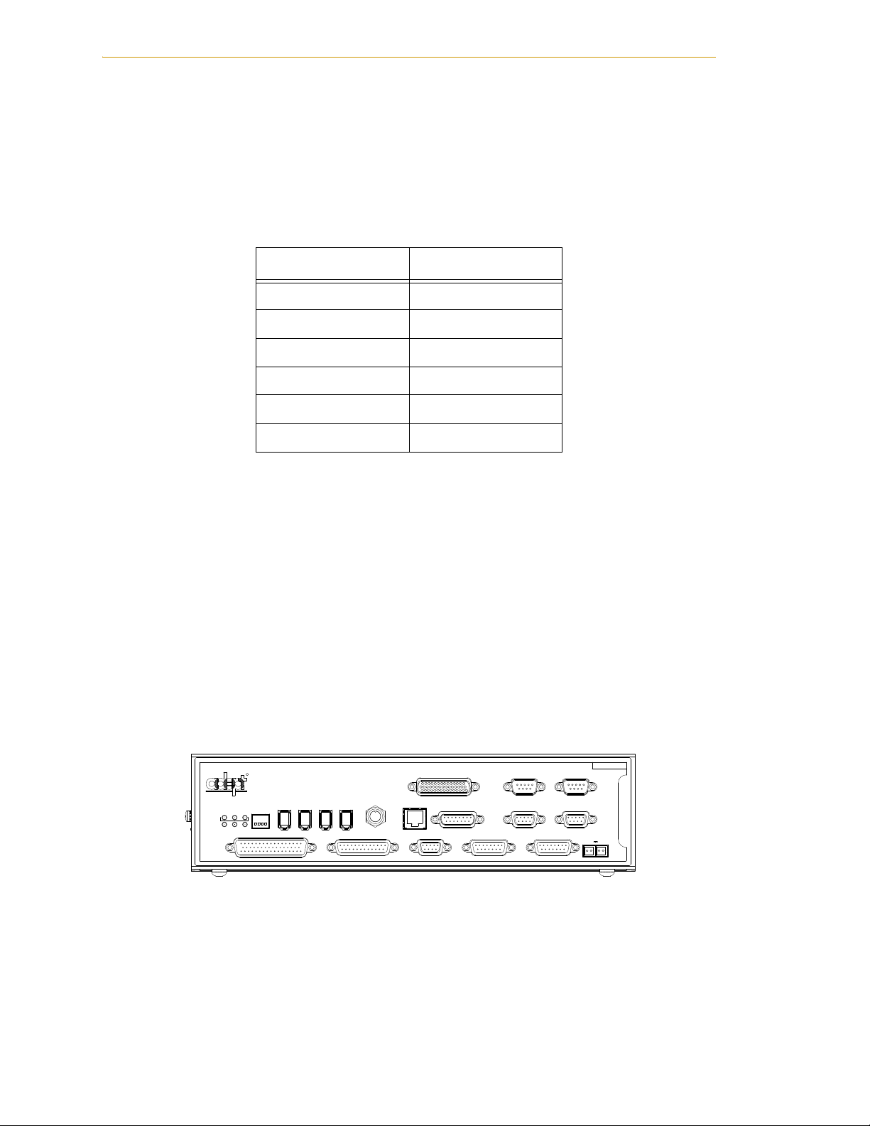
Adept SmartController CX™
The SmartController CX motion controller is the foundation of Adept’s family of
high-performance distributed motion controllers. The SmartController CX is designed for
use with Adept Cobra s600 and s800 robots, Adept Python Modules, Adept Viper robots,
Adept Quattro robots, and the Adept sMI6 Module for the SmartMotion product.
The SmartController CX supports a conveyor-tracking option. It offers scalability and
support for IEEE 1394-based digital I/O and general motion expansion modules. The
IEEE 1394 interface is the backbone of Adept SmartServo, Adept's distributed controls
architecture supporting Adept products. The controller also includes Fast Ethernet and
DeviceNet.
Figure 1-2. Adept SmartController CX Motion Controller
12 Adept Viper s1700D Robot User’s Guide, Rev A
Page 13

Dangers, Warnings, Cautions, and Notes
Adept PA-4™ CAT-3 Power Chassis
The PA-4 CAT-3 includes AC-DC power conversion electronics that support a range of
Adept power amplifiers and robot control modules. In addition, the PA-4 CAT-3 includes
dual (redundant) high-power AC contactors. The PA-4 is configured with H and I
Amplifier modules to support the Adept Viper 1700D robot systems.
The H and I amplifiers in the Adept Viper 1700D robot system are controlled by the sDAI
(HP) distributed control module. The sDAI module resides in the PA-4 chassis and
contains a RISC microprocessor and interface circuitry that close the servo loops for highperformance robot motion. The sDAI is connected to a host Adept SmartController via the
SmartServo interface (based on IEEE 1394).
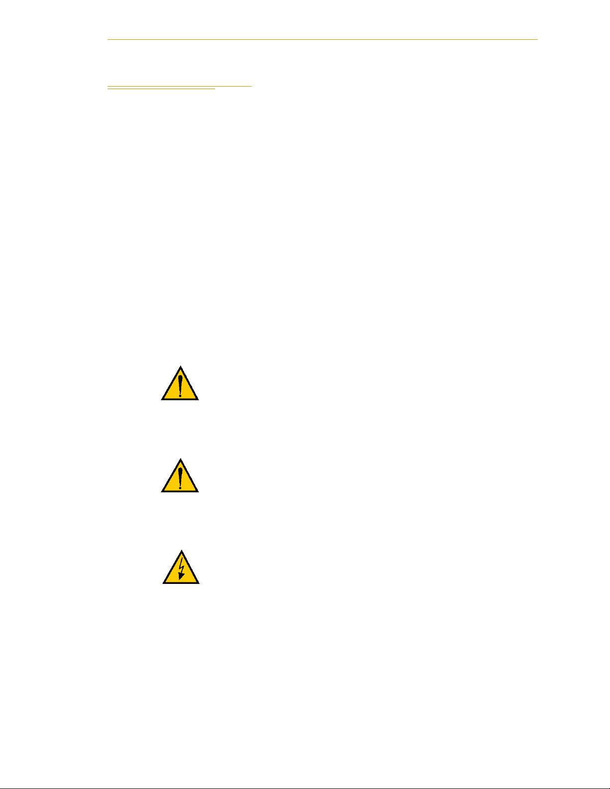
1.2 Dangers, Warnings, Cautions, and Notes
There are six levels of special alert notation used in Adept manuals. In descending order
of importance, they are:
DANGER: This indicates an imminently hazardous
electrical situation which, if not avoided, will result in
death or serious injury.
DANGER: This indicates an imminently hazardous
situation which, if not avoided, will result in death or
serious injury.
WAR NI NG : This indicates a potentially hazardous
electrical situation which, if not avoided, could result in
injury or major damage to the equipment.
WAR NI NG : This indicates a potentially hazardous
situation which, if not avoided, could result in injury or
major damage to the equipment.
CAUTION: This indicates a situation which, if not avoided,
could result in damage to the equipment.
NOTE: Notes provide supplementary information, emphasize a point or
procedure, or give a tip for easier operation.
Adept Viper s1700D Robot User’ s Guide, Re v A 13
Page 14

Introduction
1.3 Safety Precautions
DANGER: The Adept Viper s1700D robot can cause
serious injury or death, or damage to itself and other
equipment, if the following safety precautions are not
observed:
• All personnel who install, operate, teach, program, or maintain the system must
read this guide, read the Adept Robot Safety Guide, and complete a training
course for their responsibilities in regard to the robot.
• All personnel who design the robot system must read this guide, read the Adept
Robot Safety Guide, and must comply with all local and national safety
regulations for the location in which the robot is installed.
• The robot system must not be used for purposes other than described in Section
1.6. Contact Adept if you are not sure of the suitability for your application.
• The user is responsible for providing safety barriers around the robot to prevent
anyone from accidentally coming into contact with the robot when it is in motion.
• Power to the robot and its power supply must be locked out and tagged out before
any maintenance is performed.
1.4 What to Do in an Emergency Situation
Press any E-Stop button (a red push-button on a yellow background/field) and then
follow the internal procedures of your company or organization for an emergency
situation. If a fire occurs, use CO
to extinguish the fire.
2
1.5 Additional Safety Information
Adept provides other sources for more safety information:
Manufacturer’s Declaration of Compliance (MDOC)
This lists all standards with which each robot complies. See “Manufacturer’s
Declaration” on page 15.
Adept Robot Safety Guide
The Adept Robot Safety Guide provides detailed information on safety for Adept robots.
It also gives resources for more information on relevant standards.
It ships with each robot manual, and is also available from the Adept Document Library.
See “Adept Document Library” on page 17.
14 Adept Viper s1700D Robot User’s Guide, Rev A
Page 15

1.6 Intended Use of the Robot
The Adept Viper s1700D robot is intended for use in parts assembly and material
handling for payloads not to exceed 20 kg. See Chapter 2 for complete information on
tooling and payloads.
1.7 Installation Overview
The system installation process is summarized in the following table. Refer also to the
system cable diagram in Figure 3-1 on page 39.
NOTE: For dual-robot installations, see the Adept Viper Dual Robot
Configuration Procedure, which is available in the Adept Document
Library.
Table 1-2. Installation Overview
Task to be Performed Reference Location
Intended Use of the Robot
1. Mount the robot on a flat, secure mounting surface. See Section 2.5 on page 26.
2. Install the SmartController, Front Panel, and Adept
ACE software.
3. Install the PA-4 power chassis. See Section 3.5 on page 41.
4. Install the IEEE 1394 and XSYS cables between
the PA-4 and SmartController.
5. Install the Power and Encoder cables between the
PA-4 and the robot.
6. Connect AC power to the PA-4 power chassis. See Section 3.6 on page 43.
7. Start the Adept ACE software, connect to the
controller, and turn on power to the system.
1.8 Manufacturer’s Declaration
The Manufacturer’s Declaration of Incorporation and Conformity lists all standards for
which the Adept Viper robot system complies. It can be found on the Adept Web site, in
the Download Center of the Support section.
See Section 3.2 on page 40.
See Section 3.5 on page 41.
See Section 3.5 on page 41.
See Section 4.1 on page 47.
ftp://ftp1.adept.com/Download-Library/Manufacturer-Declarations/
Each Manufacturer's Declaration is supplied in PDF format and stored on the website in a
ZIP archive. To access the PDF document:
1. Click on the appropriate .zip file. You are prompted to Open or Save the file.
2. Click Open to open the file and display the archive contents.
Adept Viper s1700D Robot User’ s Guide, Re v A 15
Page 16

Introduction
3. Double-click on a .pdf file to open it.
1.9 How Can I Get Help?
Refer to the How to Get Help Resource Guide (Adept P/N 00961-00700) for details on
getting assistance with your Adept software and hardware. Additionally, you can access
information sources on Adept’s corporate web site:
http://www.adept.com
• For Contact information:
http://www.adept.com/contact/americas
http://www.adept.com/contact/asiapacific-rim
http://www.adept.com/contact/europe
• For Product Support information:
http://www.adept.com/support/service-and-support/main
• For user discussions, support, and programming examples:
http://www.adept.com/forum/
• WEEE/RoHS, Policy:
ftp://ftp1.adept.com/Download-Library/Regulatory/
• WEEE Drop-off Sites:
http://www.adept.com/contact/americas
http://www.adept.com/contact/asiapacific-rim
http://www.adept.com/contact/europe
The Download Center (ID # 500080) provides Adept WEEE/RoHS Policy. The
Contact area of the web site gives locations of WEEE drop-off sites.
Related Manuals
This manual covers the installation, operation, and maintenance of an Adept Viper
s1700D robot system. There are additional manuals that cover programming the system,
reconfiguring installed components, and adding other optional components; see Ta bl e
1-3. These manuals are available on the Adept Document Library CD-ROM shipped with
each system.
Table 1-3. Related Manuals
Manual Title Description
Adept Robot Safety Guide Contains safety information for Adept robots.
Adept SmartController
User’s Guide
Adept PA-4 Power Chassis
User’s Guide
Adept T2 Pendant User’s
Guide
16 Adept Viper s1700D Robot User’s Guide, Rev A
Contains complete information on the installation and oper ation
of the Adept SmartController and the optional sDIO product.
Contains complete information on the installation and oper ation
of the PA-4 Power Chassis.
Describes the Adept T2™ pendant product.
Page 17

Table 1-3. Related Manuals (Continued)
Manual Title Description
Adept IO Blox User’s Guide Describes the IO Blox™ product.
Manufacturer’s Declaration
Adept Viper Dual Robot
Configuration Procedure
Instructions for Adept
Utility Programs
Contains cable diagrams and configuration procedures for a
dual-robot system.
Describes the utility programs used for advanced system
configurations, system upgrades, file cop ying, and other system
configuration procedures.
+
V+ Operating System User’s
Guide
Describes the V
operations, monit or commands, and monitor command
operating system, including disk file
programs.
+
V+ Language User’s Guide Describes the V
language and programming of an Adept
control system.
Adept Document Library
The Adept Document Library (ADL) contains documentation for Adept products. You
can access the ADL from:
• the Adept Software CD shipped with your system
• the Adept Web site. Select Document Library from the Adept home page. To go
directly to the Adept Document Library, type the following URL into your
browser:
http://www.adept.com/Main/KE/DATA/adept_search.htm
To locate information on a specific topic, use the Document Library search engine on the
ADL main page. To view a list of available product documentation, select the Document
Titles option.
Adept Viper s1700D Robot User’ s Guide, Re v A 17
Page 18

Introduction
18 Adept Viper s1700D Robot User’s Guide, Rev A
Page 19

Robot Installation 2
2.1 Unpacking and Inspecting the Adept Equipment
Before Unpacking
Carefully inspect all shipping crates for evidence of damage during transit. Pay special
attention to tilt and shock indication labels on the exteriors of the containers, if installed. If
any damage is indicated, request that the carrier’s agent be present at the time the
container is unpacked.
Upon Unpacking
Before signing the carrier’s delivery sheet, please compare the actual items received (not
just the packing slip) with your equipment purchase order and verify that all items are
present and that the shipment is correct and free of visible damage.
If the items received do not match the packing slip, or are damaged, do not sign the
receipt. Contact Adept as soon as possible.
If the items received do not match your order, please contact Adept immediately.
Inspect each item for external damage as it is removed from its container. If any damage is
evident, contact Adept (see Section 1.9 on page 16).
Retain all containers and packaging materials. These items may be necessary to settle
claims or, at a later date, to relocate equipment.
Adept Viper s1700D Robot User’s Guide, Rev A 19
Page 20

Robot Installation
2.2 Environmental and Facility Requirements
The Adept robot system installation must meet the operating environment requirements
shown in Table 2-1.
Table 2-1. Robot System Operating Environment Requirements
Item Condition
Flatness of the mounting
surface
Installation type Floor-mount or inverted (ceiling-mount)
Ambient temperature During operation: 0° to 45° C (32° to 113° F)
Humidity During operation: 20 to 80% (no moisture at constant
Vibration During operation: 4.9 m/s
Safe Installation
Environment
0.5 mm or less
During storage and transportation: -10° to 60° C (14° to 140° F)
temperature allowed).
During storage and transportation: 75% or less
(non-condensing).
2
(0.5G) or less
During storage and transportation: 29.4 m/s
The robot should not be installed in an environment where:
• there are flammable gases or liquids
• there are any acidic, alkaline, or other corrosive gases
• there is sulfuric or other types of cutting or grinding oil mist,
or
• there are any large-sized inverters,
high-output/high-frequency tran smitters, large contactors,
welders, or other sources of electrical noise
• there are any shavings from metal processing or other
conductive material flying about
• it may be directly exposed to water, oil, or cutting chips
2
(3G) or less
Working space, etc. • Sufficient service space must be available for inspection and
disassembly.
• Keep wiring space (230 mm or more) behind the robot, and
fasten the wiring to the mounting face or beam so that the
weight of the cables will not be directly applied to the
connectors.
Installation conditions Grounding resistance: 100 milliohms or less
See Section 2.6 on page 30.
20 Adept Viper s1700D Robot User’s Guide, Rev A
Page 21
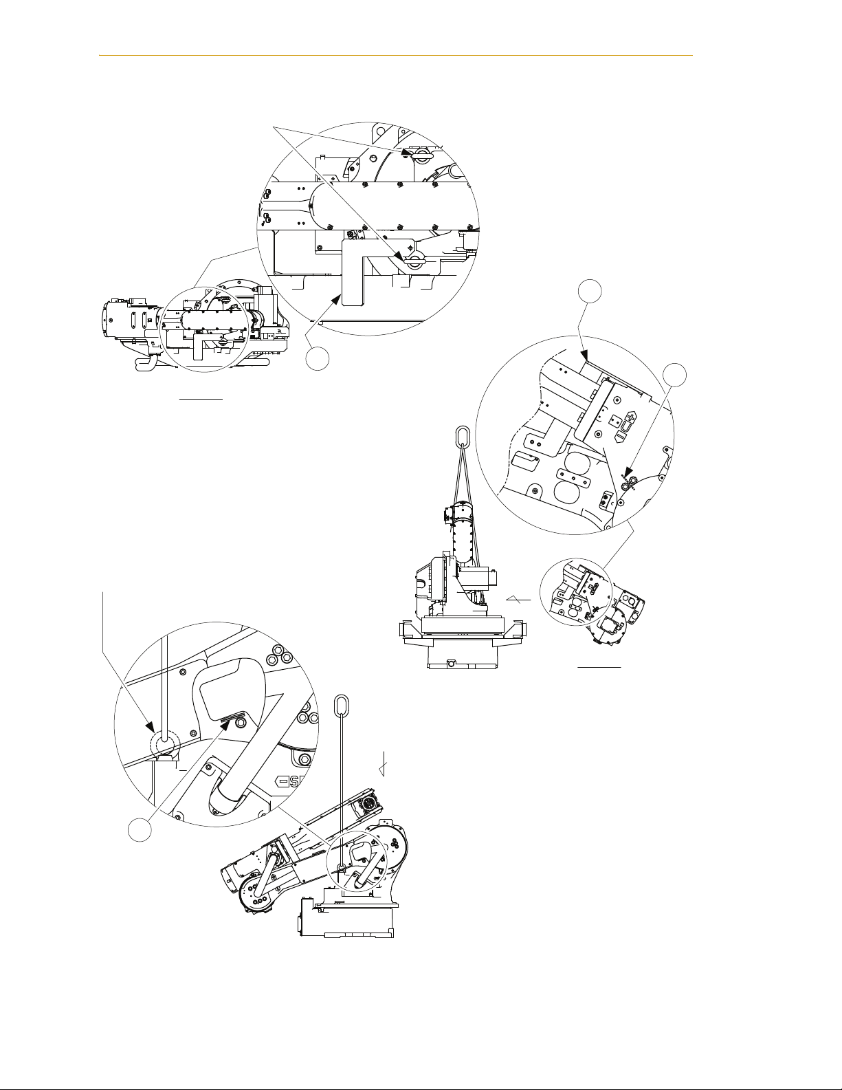
2.3 Transporting the Robot
Precautions
When transporting the robot, note the following:
• Check that the eyebolts are securely fastened.
• Use a wire sling or forklift that is strong enough to withstand the weight. (The
weight of the robot is approximately 268 kg (590 lb) including the shipping bolts
and brackets.)
• Attached eyebolts are designed to support the robot’s weight. Do not use them for
anything other than transporting the robot.
• Mount the shipping bolts and brackets for transporting the robot. See Figure 2-1
on page 22.
• Avoid exerting force on the arm or motor unit when transporting.
• Have at least two workers transport and install the robot.
Unpacking and Inspecting the Adept Equipment
• Workers should wear helmets, safety shoes, and gloves during transport.
CAUTION: Sling and crane or forklift operations must be
performed by authorized personnel only.
CAUTION: Avoid excessive vibration or shock during
transporting. The system consists of precision
components, so failure to observe this caution my
adversely affect performance.
DANGER: Pass the hoisting wires through the specified
eyebolts as illustrated below. Passing them through other
sections may drop the robot unit, resulting in injuries to
personnel or damage to the robot.
Using a Crane
As a rule, when removing the robot from the package and moving it, a crane should be
used. The robot should be lifted using wire slings threaded through the attached eyebolts.
Make sure the robot is fixed with shipping bolts and brackets before transporting, and lift
it into the position shown in Figure 2-1 on page 22.
Adept Viper s1700D Robot User’ s Guide, Re v A 21
Page 22
Robot Installation
F
B
D
View F
A
View E
Eyebolt M12 (2 eyebolts)
(Delivered with the robot)
E
Eyebolt M12 (2 eyebolts)
(Delivered with the robot)
C
Figure 2-1. Robot in Hoisting Sling
22 Adept Viper s1700D Robot User’s Guide, Rev A
Page 23
Unpacking and Inspecting the Adept Equipment
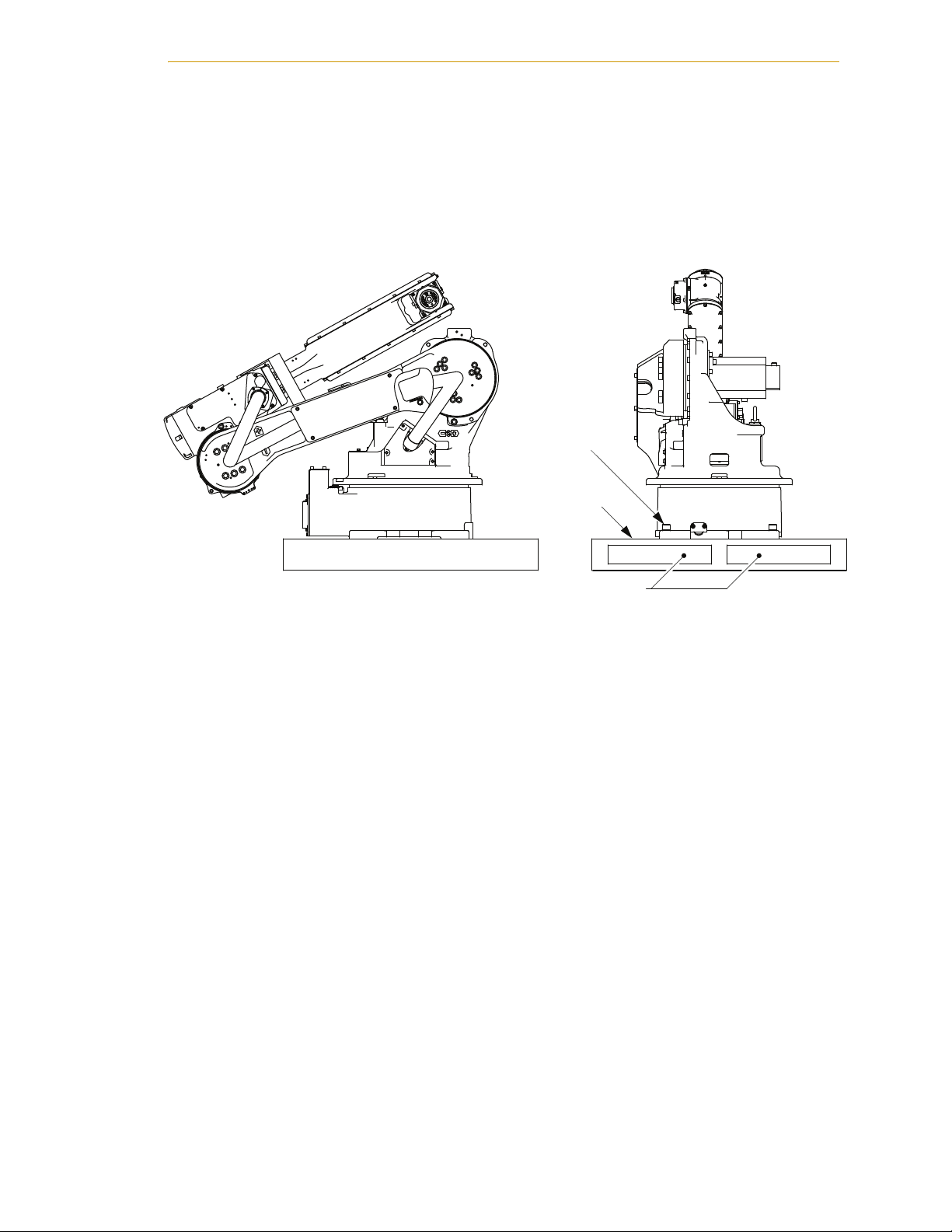
Using a Forklift
When using a forklift, the robot should be fixed on a pallet with shipping bolts and
brackets, as shown in Figure 2-2. Insert the forklift blades under the pallet and lift it. The
pallet must be strong enough to support the robot. Transportation of the robot must be
performed slowly in order to avoid overturning, slippage, or damage.
Bolts M16 (4 bolts)
Pallet
Forklift blade entry
Figure 2-2. Using a Forklift
Adept Viper s1700D Robot User’ s Guide, Re v A 23
Page 24
Robot Installation
Enlarged View: Section A Enlarged View: Section C Enlarged View: Sections B and D
Parts Drawing for Section A Parts Drawing for Section B
Eyebolts M12 (2 eyebolts)
(delivered with the robot)
D
B
C
A
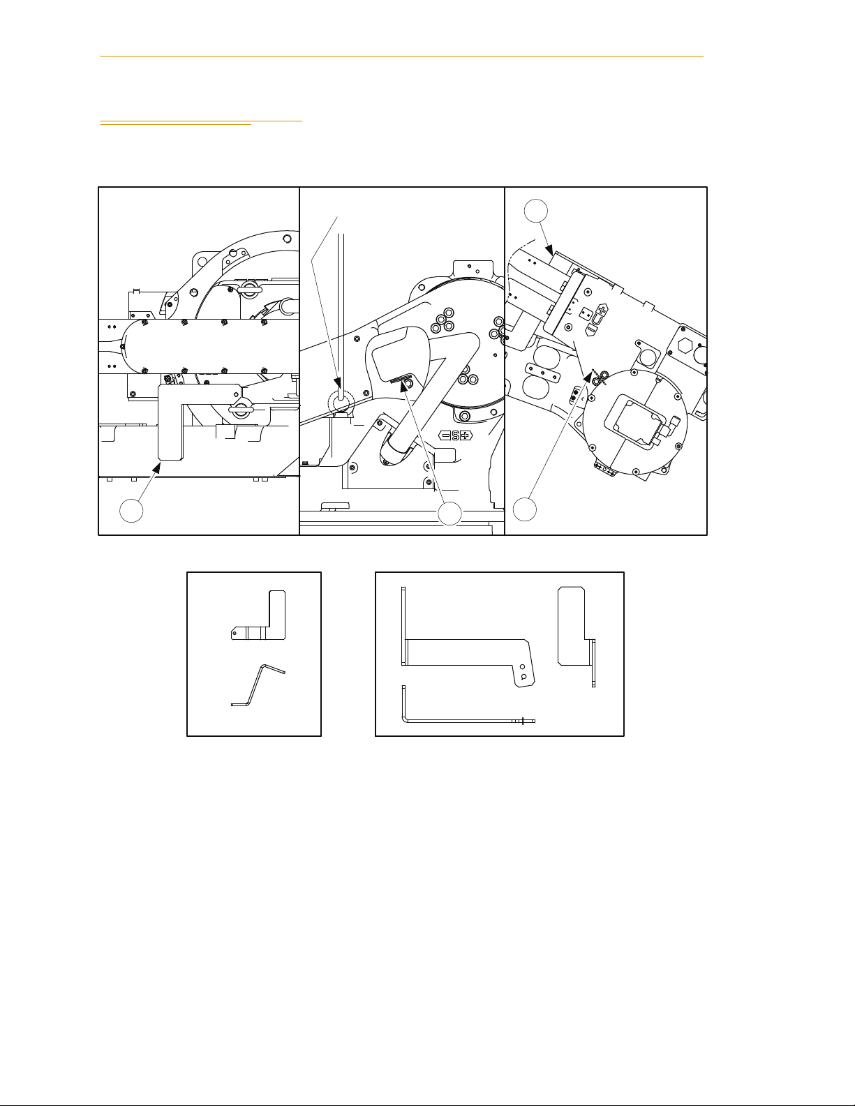
2.4 Shipping Bolts and Brackets
The robot is provided with shipping bolts and brackets at points A and B (see Figure 2-3).
Figure 2-3. Shipping Bolts and Brackets
24 Adept Viper s1700D Robot User’s Guide, Rev A
Page 25

Shipping Bolts and Brackets
• The shipping brackets (A and B) are painted yellow (see Figure 2-3 on page 24).
• A hexagon socket head cap screw (M8) is attached at point A, and two hexagon
socket head cap screws (M6) are attached at point B, as fixing jigs (see Figure 2-3
on page 24).
• A rubber cushion is wedged at points C and D (see Figure 2-3 on page 24).
CAUTION: Before turning on the power, make sure that
the robot is securely mounted to its mounting base and
that the shipping bolts, brackets, and rubber cushions
have been removed. Then store these parts for future use
(in the event that the robot must be moved again).
Adept Viper s1700D Robot User’ s Guide, Re v A 25
Page 26

Robot Installation
395.5
195.5
60
±0.1
60
200
200
±0.1
260
170
±0.1
335
375
A
25
250
313
335
375
Fitting surface
Fitting surface
±0.1
(for robot fixing)
View A
18 dia. holes (4 holes)
12 dia. holes
(2 holes)
+0.018
0
Units: mm
2.5 Mounting the Robot
Types of Mounting
The robot can be mounted in two different ways: floor-mounted (standard) and
ceiling-mounted types are available. For ceiling mounting, see also “Mounting on a
Ceiling” on page 29.
Figure 2-4. Robot Base Dimensions
26 Adept Viper s1700D Robot User’s Guide, Rev A
Page 27

Shipping Bolts and Brackets
200±0.1
250
313
60
260±0.1
335
375
200±0.1
4X Ø 18 THRU
170±0.1
2X Ø12
335 375
+0.018
-0.0
Units are mm
Figure 2-5. Mounting Hole Pattern for Robot
Adept Viper s1700D Robot User’ s Guide, Re v A 27
Page 28

Robot Installation
Mounting the Robot Base
Mount the robot on a base or foundation strong enough to support the robot and
withstand repulsion forces during acceleration and deceleration. Refer to Table 2-2 and
Table 2-3 to construct a solid foundation with the appropriate thickness to withstand
maximum repulsion forces of the robot. During installation, if the flatness is not correct,
the robot shape may change and its functional ability may be compromised. The flatness
for installation must be kept at 0.5 mm or less. Mount the robot base as described below.
Table 2-2. Maximum Repulsion Forces of Robot at Emergency Stop
Maximum horizontal rotating
torque
(direction of motion Axis 1)
Maximum vertical rotating
torque
(direction of motion Axes 2
and 3)
Table 2-3. Endurance Torque in Operation
Maximum horizontal torque
(direction of motion Axis 1)
Maximum vertical torque
(direction of motion Axes 2
and 3)
1. Fix the base plate with the anchor bolts on the floor. The base plate should be
rugged and durable. It is recommended that the thickness of the base plate be
32 mm or more and the anchor bolt size be M16 or larger.
2. Fix the robot base with the hexagon socket head cap screws on the base plate.
3. There are four mounting holes on the robot base. Fix the robot securely with the
hexagon socket head cap screws M16 (60 mm long recommended; tensile
strength: 1200 N/mm
2
or above). Tighten the bolts to 206 N•m torque.
8000 N•m
(5900 ft•lbf)
5000 N•m
(3688 ft•lbf)
1700 N•m
(1254 ft•lbf)
3775 N•m
(2784 ft•lbf)
NOTE: Tighten the anchor bolts and hexagon socket head cap screws
securely so that they do not work loose during operation.
28 Adept Viper s1700D Robot User’s Guide, Rev A
Page 29

Shipping Bolts and Brackets
Bolt M16 (4 bolts)
Spring washer
Washer
Robot base
25
40 mm
or more
Robot base
Anchor bolt (M16 or larger)
Baseplate
Figure 2-6. Mounting the Robot Baseplate
NOTE: See Figure 2-5 on page 27 for the mounting hole pattern.
Mounting on a Ceiling
NOTE: For ceiling-mounted installations, contact Adept.
For ceiling-mounted types, the following points apply:
Baseplate
• Affixing the robot base
• Precautions to prevent the robot from falling
See the sections below for details.
NOTE: For ceiling mounted installations, environmental resistance for the
main part of the robot does not conform to IP-54. For the wrist part, the
resistance conforms to IP-67.
Affixing the Robot Base
When performing a ceiling mount, use four M16 hexagon socket head cap screws (tensile
2
strength: 1200 N/mm
). Tighten to a torque of 206 N•m.
Precautions to Prevent the Robot from Falling
When performing a ceiling mount, for safety purposes, take measures to keep the robot
from falling. See Figure 2-7 for details.
Adept Viper s1700D Robot User’ s Guide, Re v A 29
Page 30

Robot Installation
Robot base
Preventive support from falling
Hexagon socket head cap screws M16 (4 screws)
(Tensile strength: 1200 N/mm2)
Figure 2-7. Ceiling Mounting
2.6 Grounding the Robot
DANGER: Ground the grounding terminal of the robot
unit with a wire of 5.5 mm
must be less than 100 milliohms.
NOTE: Use a dedicated grounding wire and grounding electrode. Do not
share them with any other electric power or power equipment, such as a
welder. When metal ducts, metallic conduits, or distributing racks are
used for laying cable, ground in accordance with Electric Equipment
Technical Standards.
WAR NI NG : Wiring must be performed by authorized or
certified personnel. Failure to observe this caution may
result in fire or electric shock.
2
or more. Ground resistance
30 Adept Viper s1700D Robot User’s Guide, Rev A
Page 31

Grounding the Robot
A
5.5 mm2 or more
Bolt M8 (for grounding)
(delivered with the robot)
Figure 2-8. Ground Point on Robot
A
Section A-A
Adept Viper s1700D Robot User’ s Guide, Re v A 31
Page 32

Robot Installation
2.7 Connectors on Robot Interface Panel
3BC
2BC
1BC
Connector details
(Robot side)
Figure 2-9. Robot Interface Panel
1BC - the Encoder cable from the PA-4 is installed at this connector.
2BC - the Power cable from the PA-4 is installed at this connector.
2
3BC - Internal user I/O wiring harness (0.2 mm
x 10 conductors and 1.25 mm2 x 6
conductors). Pins 1 to 16 are wired directly to corresponding pins 1 to 16 on the upper
arm. The connector pins are assigned as shown in Figure 2-11 on page 33. The user must
perform the wiring. The allowable current for cables is 3 A or less for each cable. The total
current value for pins 1 to 16 must be 40 A or less. See also Figure 2-10 on page 33.
AIR inlet - air piping connector (PT 3/8 with pipe plug) for driving peripheral devices on
the upper arm. See also Figure 2-10 on page 33. The maximum pressure for the air lines is
490 kPa (4.9 Bar) or less. The inside diameter is 6.5 mm.
32 Adept Viper s1700D Robot User’s Guide, Rev A
Page 33

2.8 Air Lines and Signal Wiring
Connector for internal user I/O
Prepare pin connector
wiring harness: JL05-2A20-29SC
(socket connector with a cap)
JL05-6A20-29P in the Adept
kit, P/N 90660-10010.
Exhaust port (air flow):
Tapped hole PT3/8 with
pipe plug
A
2BC
1BC
3BC
Air inlet: Tapped hole
PT3/8 with pipe plug
View A
Connector for internal
user I/O wiring harness:
JL05-2A20-29PC
(pin connector with a cap)
Prepare socket connector
JL05-6A20-29S in the Adept
kit, P/N 90660-10010.
Connectors on Robot Interface Panel
Connectors on 3rd axis
1
6
10
14
8
12
7
11
5
16
15
4
9
13
2
3
3
4
5
1
2
9
10
11
16
15
13
14
12
6
Pins used
Internal user I/O wiring harness : 0.2 mm
2
, 8 lead wires
: 1.25 mm
2
, 6 lead wires
(1.25 mm2)
(1.25
mm2)
(1.25
mm2)
(1.25
mm2)
(1.25
mm2)
7
8
(+24V: for shock sensor)
(Shock sensor signal input)
1
6
10
14
8
12
7
11
5
16
15
4
9
13
2
3
3
4
5
1
2
9
10
11
16
15
13
14
12
6
Pins used
(1.25 mm2)
(1.25
mm2)
(1.25
mm2)
(1.25
mm2)
(1.25
mm2)
7
8
(Open)
(Open)
Internal user I/O wiring harness : 0.2 mm2, 8 lead wires
: 1.25 mm
2
, 6 lead wires
Connector for Internal User I/O Wiring Harness
on the Robot Interface Panel
Connector for Internal User I/O Wiring Harness
on the 3rd Axis-Arm
Connectors on Robot Interface Panel
Figure 2-10. Internal User I/O Wiring Harness and Air Line
Figure 2-11. Connector Pin Numbers
Adept Viper s1700D Robot User’ s Guide, Re v A 33
Page 34

Robot Installation
W1
W2
70
70
220
A
View A
Units: mm
Z-coordinate
direction
Center of 3rd-axis rotation
Limited dimension
of Z-coordinate:
400 at a maximum
X-coordinate
direction
Tapped holes M6
(depth: 10)
(pitch: 1.0) (4 holes)
External Mounting Locations on Robot
When attaching external equipment to the 3rd axis, install the equipment as described in
this section.
Allowable Load
The maximum allowable load on the 3rd axis is 31 kg, including the wrist load. For
example, when the mass installed on the wrist point is 20 kg, the allowable mass that can
be installed on the upper arm is 11 kg.
Installation Position
Observe the limitations on the installation position shown in Figure 2-12. Figure 2-13
shows the distance between the center of the 3rd-axis rotation and the load gravity.
34 Adept Viper s1700D Robot User’s Guide, Rev A
Figure 2-12. Installing External Equipment Mounts
Page 35

Weight W2
(kg)
30
20
10
W1=10kg
W1=16kg
W1=20kg
W1=6kg
*1
Designing End-Effectors
*1 In this case, unbalanced
moment is not permitted
0
-200 -100
Distance between Center of 3rd-axis
Rotation and Load Gravity (X direction)
1000
Figure 2-13. Allowable Load on Third Axis
2.9 Designing End-Effectors
Design an end-effector such that it is in compliance with items described in this section.
CAUTION: If the end-effector design precautions are not
observed, the clamped parts of the robot may become
loose, rattle, or be out of position. In the worst case, the
mechanical parts of the robot and robot controller may
become damaged.
Mass of End-Effector
Design the end-effector so that the total mass of the end-effector (including workpiece)
will be lighter than the maximum payload capacity of the robot. The total mass includes
the wiring, tubing, etc.
(mm)500200 300 400
Maximum total mass of the end-effector (including workpiece) must be less than or equal
to the maximum payload capacity (20 kg).
If force is applied to the 5th axis instead of the payload, force on the 4th, 5th, and 6th axes
should be within the values shown in Table 2-4. Contact Adept Customer Service for
additional information.
Adept Viper s1700D Robot User’ s Guide, Re v A 35
Page 36

Robot Installation
L
L
105
T
B
400
300
W=6Kg
W=10Kg
200100
200
100
0
W=20Kg
W=16Kg
300
L
T
(mm)
LB (mm)
5th-axis rotation center line
6th-axis, 4th-axis
rotation center line
Load gravity
position
Table 2-4. Allowable Moment and Inertia
Axis
Moment N•m (ft•lbf)
a
Inertia kg•m
2
4th axis 39.2 (29.0) 1.05
5th axis 39.2 (29.0) 1.05
6th axis 19.6 (14.5) 0.75
a
(): Gravitational unit
When the volume load is small, refer to the moment arm rating shown in Figure 2-14.
The allowable inertia is calculated when the moment is at the maximum. Contact Adept
Customer Service when only load moment is small and inertia moment is large. Also,
contact Customer Service when the load mass is combined with an outside force.
Figure 2-14. Moment Arm Rating
Wrist Tool Flange
See Figure 2-15 for the dimensions of the wrist tool flange. To see the alignment marks, it
is recommended that the attachment be mounted inside the fitting. The fitting depth of
the inside and outside fittings must be 5 mm or less.
NOTE: Use thinner or light oil to clean off the anti-corrosive material on
the tool flange area prior to mounting the end-of-arm tooling.
NOTE: Mount the attachment with the mounting bolts (length: 10 mm or
less). Failure to due this may affect robot performance.
36 Adept Viper s1700D Robot User’s Guide, Rev A
Page 37

Alignment mark
0.5
6
6
+0.021
0
25 dia.
A
0
-0.039
50 dia.
Designing End-Effectors
Units: mm
45°
Tapped holes M6
(depth: 10)
(pitch: 1.0) (4 holes)
P.C.D40
View A
Figure 2-15. Wrist Tool Flange
+0.012
6 dia. hole
0
(depth: 6)
Adept Viper s1700D Robot User’ s Guide, Re v A 37
Page 38

Robot Installation
38 Adept Viper s1700D Robot User’s Guide, Rev A
Page 39

CAUTION
HIGH
VOLTAGE
INSIDE
B
R
A
K
E
STATUS
SmartServo
1
2
R
S
2
3
2
E
X
P
I
O
X
S
L
V
C
N
P
G
1
2
3
C
N
P
G
4
5
6
C
N
2
5
C
N
2
9
DAI
s
adept
technology, inc.
LOW VOLTS ON
HV SAG/OVER TEMP FAULT
DO NOT REMOVE OR INSTALL THIS
SHORT FAULT
OPEN CKT FAULT
MODULE UNLESS HIGH VOLTS LED
IS COMPLETELY DISTINGUISHED
PWM ON
CH1
HIGH VOLTS ON
CH2
A
M
P
L
I
F
I
E
R
C
O
N
T
R
O
L
CH2CH1
M
O
T
O
R
P
O
W
E
R
O
U
T
P
U
T
K AMP K AMP J AMP
LOW VOLTS ON
HV SAG/OVER TEMP FAULT
DO NOT REMOVE OR INSTALL THIS
SHORT FAULT
OPEN CKT FAULT
MODULE UNLESS HIGH VOLTS LED
IS COMPLETELY DISTINGUISHED
PWM ON
CH1
HIGH VOLTS ON
CH2
A
M
P
L
I
F
I
E
R
C
O
N
T
R
O
L
CH2CH1
M
O
T
O
R
P
O
W
E
R
O
U
T
P
U
T
LOW VOLTS ON
HV SAG/OVER TEMP FAULT
DO NOT REMOVE OR INSTALL THIS
SHORT FAULT
OPEN CKT FAULT
MODULE UNLESS HIGH VOLTS LED
IS COMPLETELY DISTINGUISHED
PWM ON
CH1
HIGH VOLTS ON
CH2
A
M
P
L
I
F
I
E
R
C
O
N
T
R
O
L
CH2CH1
M
O
T
O
R
P
O
W
E
R
O
U
T
P
U
T
Ethernet to PC
IEEE 1394 Cable
Adept PA-4
Power Chassis
Adept
SmartController CX
Adept Viper s1700D
Robot
User-Supplied
Power Supply
200-240 VA C 3-Phase
or
380-415 VA C 3-Phase
Controller (XFP) to
Front Panel (XFP)
Front Panel
T2 Pendant
(optional)
XSYS cable
24VDC Power Cable
(User-Supplied)
User-supplied PC
running Adept ACE
Terminator
Installed
User-Supplied
Ground Wire
Power Cable
Encoder Cable
H Amp
I Amp
H Amp
sDAI Module
(HP)
HP
STOP
R
R
ON
SmartServo IEEE-1394
1 2 3 4
SF ES HD
SW1
1.1 1.2 2.1 2.2
OK
123
XDIO
LANHPE
OFF
XSYS
CAMERA
Eth 10/100
XUSR
Device Net
XFP
RS-232/TERM
RS-232-1
XMCP
BELT ENCODER
SmartController CX
-+ -+
RS-422/485
XDC1 XDC2
24V 5A
*S/N 3562-XXXXX*
RS-232-2
3.1 System Cable Diagram
System Installation 3
Figure 3-1. System Cable Diagram for Adept Viper s1700D Robot
Adept Viper s1700D Robot User’s Guide, Rev A 39
Page 40

System Installation
3.2 Installing the SmartController
Refer to the Adept SmartController User’s Guide for complete information on installing
the Adept SmartController. This list summarizes the main steps.
1. Mount the SmartController and Front Panel.
2. Connect the Front Panel to the SmartController.
3. Connect the optional pendant to the SmartController, if included.
4. Connect user-supplied 24 VDC power to the controller.
5. Install a user-supplied ground wire between the SmartController and ground.
6. Install the Adept ACE PC software on the user-supplied PC. This includes
connecting the supplied Ethernet crossover cable between the user-supplied PC
and the Ethernet port on the SmartContoller.
3.3 Installing the Adept ACE Software
The Adept ACE software is installed from the Adept ACE software CD-ROM.
1. Insert the CD-ROM into the CD-ROM drive of your PC.
If Autoplay is enabled, the Adept software CD-ROM menu is displayed. If
Autoplay is disabled, you will need to manually start the CD-ROM.
2. Especially if you are upgrading your Adept ACE software installation: from the
Adept ACE software CD-ROM menu, click Read Important Information.
3. From the Adept ACE software CD-ROM menu, select:
Install the Adept ACE Software
The Adept ACE Setup wizard opens.
4. Follow the online instructions as you step through the installation process.
5. When the installation is complete, click Finish.
6. After closing the Adept ACE Setup wizard, click Exit on the CD-ROM menu to
close the menu.
NOTE: You will have to restart the PC after installing the Adept ACE
software.
40 Adept Viper s1700D Robot User’s Guide, Rev A
Page 41

Connecting the PC to the SmartController
3.4 Connecting the PC to the SmartController
The Adept SmartController motion controller must be connected to a user-supplied PC or
the Adept SmartVision EX processor for setup, control, and programming.
• Connect an Ethernet crossover cable between the PC and the SmartController
motion controller
or
• Use two standard Ethernet cables with a network hub or switch in place of the
Ethernet crossover cable.
NOTE: Do not use an Ethernet crossover cable with a network hub or
switch.
For more details, refer to the Adept ACE User’s Guide.
3.5 Installing the PA-4 Power Chassis
Refer to the Adept PA-4 Power Chassis User’s Guide for complete information on the
PA-4 chassis. This list summarizes the main steps.
1. Mount the PA-4 chassis.
NOTE: For the PA-4 in an Adept Viper system, only the panel-mounting
option is available.
2. Locate these cables, shipped in the cable/accessories box.
• IEEE 1394 cable (length 4.5 M)
• XSYS cable (length 4.5 M)
• Power cable (length 7 M)
• Encoder cable (length 7 M)
NOTE: The IEEE 1394 and XSYS cables should be routed away from the
AC power and robot Power and Encoder cables.
3. Install one end of the IEEE 1394 cable into the SmartServo port 1.1 connector on
the SmartController, and install the other end into the SmartServo port 1
connector on the sDAI module in the PA-4. See Figure 3-1 on page 39 and Figure
3-2 on page 42. Make sure the plug is oriented correctly to the connector.
4. Install the XSYS cable between the XSYS connector on the SmartController, and
the XSLV connector on the sDAI module, and tighten the latching screws.
5. Install the Power cable between the 2BC connector on the robot and the power
connector shown in Figure 3-2 on the PA-4. Insert the connector and then push
down the lever until you hear a click.
6. Install the Encoder cable between the 1BC connector on the robot and the encoder
connector shown in Figure 3-2 on the PA-4. Insert the connector and then push
down the lever until you hear a click.
Adept Viper s1700D Robot User’ s Guide, Re v A 41
Page 42

System Installation
Latching Screws
Interface Box
Power Connector
H-Amp
I-Amp
H-AMP I-AMP H-AMP
DO NOT REMOVE OR INSTALL THIS
DO NOT REMOVE OR INSTALL THIS
MODULE UNLESS HIGH VOLTS LED
IS COMPLETELY DISTINGUISHED
HIGH VOLTS ON
PWM ON
LOW VOLTS ON
OPEN CKT FAULT
HV SAG/OVER TEMP FAULT
SHORT FAULT
CH1
CH2
A
M
P
L
I
F
I
E
R
C
O
N
T
R
O
L
M
O
T
O
R
P
O
W
E
R
O
U
T
P
U
T
CH2CH1
DO NOT REMOVE OR INSTALL THIS
MODULE UNLESS HIGH VOLTS LED
IS COMPLETELY DISTINGUISHED
CH1
CH2
MODULE UNLESS HIGH VOLTS LED
IS COMPLETELY DISTINGUISHED
HIGH VOLTS ON
PWM ON
LOW VOLTS ON
OPEN CKT FAULT
HV SAG/OVER TEMP FAULT
SHORT FAULT
CH1
CH2
A
M
P
L
I
F
I
E
R
C
O
N
T
R
O
L
M
O
T
O
R
P
O
W
E
R
O
U
T
P
U
T
adept
technology, inc.
CH2CH1
HIGH VOLTS ON
PWM ON
LOW VOLTS ON
OPEN CKT FAULT
HV SAG/OVER TEMP FAULT
SHORT FAULT
A
M
P
L
I
F
I
E
R
C
O
N
T
R
O
L
H-Amp
B
R
A
K
E
1
SmartServo
2
C
N
P
G
1
2
3
CH2CH1
s
DAI
CAUTION
VOLTAGE
INSIDE
sDAI Module (HP)
Brake Release
HIGH
Status Panel
STATUS
R
S
2
RS-232
3
2
SmartServo 1 & 2
E
X
P
I
EXPIO
O
XSLV
X
S
L
V
C
N
P
G
4
5
6
C
N
2
5
C
N
2
9
Encoder Connector
Figure 3-2. Adept PA-4 Power Chassis with sDAI (HP) Module
NOTE: In Adept Viper s1700D systems, the sDAI module must be an HP
version. A standard sDAI will not work.
42 Adept Viper s1700D Robot User’s Guide, Rev A
Page 43

Installing the PA-4 Power Chassis
3.6 Connecting 3-Phase AC Power to PA-4
PA-4 3-Phase Power Requirements
Table 3-1. Adept PA-4 Power Chassis 3-Phase Power Requirements
Nominal
Voltage
Range
Frequency/
Phasing
Minimum
Operating
Voltage
Maximum
Operating
Voltage
Recommended
External
Circuit Breaker
(user-supplied)
200 to 240
VAC
380 to 415
VAC
50-60Hz,
3-phase
50-60Hz,
3-phase with
180 VAC 245 VAC 20 amps
342 VAC 424 VAC 20 amps
neutral
a
Table 3-2. Typical Robot Power Consumption
Robot Move
No load - Adept cycle
Adept Viper
s1700D
20.0 kg - Adept cycle
Average Power
(W)
c
c
429 1750
532 2498
Peak Power
b
(W)
20.0 kg - all joints move 1306 6140
a
Typical power data is with 380 VAC, 60Hz, 3-phase nominal input.
b
For short durations (100 ms)
c
Adept cycle: the robot tool performs continuous path, straight-line motions 25 mm up, 305 mm
over , 25 mm down, and back along the same path. COARSE is enabled and BREAKs are used
at each end location. Not achievable over all paths.
The Adept PA-4 power chassis can be shipped from the factory configured for either
3-phase 200-240
VAC or 380-415 VAC operation, depending on your sales order.
A voltage setting label is located on the front of the chassis below the circuit breaker. The
voltage setting is also shown on the ID label on the side of the chassis. Verify that the
setting matches your facility power before installation.
If you need to change the AC voltage setting from 200-240
versa
, see the Adept PA-4 Power Chassis User’s Guide.
VAC to 380-415 VA C, o r vic e
WAR NI NG : Verify the voltage settings are correct before
turning on power. Operating the Adept PA-4 power
chassis with incorrect voltage settings can cause damage
or injury.
Adept Viper s1700D Robot User’ s Guide, Re v A 43
Page 44

System Installation
Connecting the PA-4 3-Phase AC Power Cord to AC Supply
The user end of the cord is unterminated. Connect each conductor of the power cord
securely to your AC power source, using the color code shown in Table 3-3. The
installation must meet all applicable European, international, and national standards and
regulations.
Table 3-3. 3-Phase AC Power Cord Specifications for PA-4
Cord length 3 meters ±0.1 m (9 ft 10 in ±4 in)
Cord rating 25 amps
Number and size of
5 x 2.5 mm
2
conductor size
Color code: 200 - 240 VAC
line 1
line 2
line 3
no connection
ground
black
black (or gray)
a
brown
blue (must be insulated)
green/yellow
Color code: 380 - 415 VAC
line 1
line 2
line 3
neutral
ground
a
Note: The two black wires can also be one black and one gray wire, but the
functionality is the same for either case.
black
black (or gray)
brown
blue
green/yellow
a
DANGER: Electrical hazard!
The installation of the power cord must be done by a
skilled person. The power supply can injure or kill the
person who installs the cord. An incorrect installation can
injure or kill anyone that touches the equipment in the
robot workcell.
The protective ground conductor (colored green/yellow) of the Adept PA-4 power
chassis is internally connected to the accessible metal parts of the power chassis. To
ensure electrical-shock protection, the ground conductor must be connected to a properly
grounded power source.
WAR NI NG : Ensure that a proper protective ground
connection exists before turning on the power.
44 Adept Viper s1700D Robot User’s Guide, Rev A
Page 45

Installing the PA-4 Power Chassis
Typical 3-Phase AC Power Installation Diagrams
L1
3Ø
200–240V~
20A
PE
PE
L3L3L2L2L1
Adept PA-4
3Ø 200–240V~
Figure 3-3. Typical 3-Phase 200-240 VAC Connection for PA-4 System
3Ø
380–415V~
20A
L1
PEPENNL3L3L2L2L1
Adept PA-4
3Ø 380–415V~
Figure 3-4. Typical 3-Phase 380-415 VAC Connection for PA-4 System
Adept Viper s1700D Robot User’ s Guide, Re v A 45
Page 46

System Installation
46 Adept Viper s1700D Robot User’s Guide, Rev A
Page 47

System Operation 4
4.1 Commissioning the System
Turning on the robot system for the first time is known as “commissioning the system.”
Follow the steps in this section to safely bring up your robot system. The steps include:
• Verifying installation, to confirm all tasks have been performed correctly
• Starting up the system by turning on power for the first time
• Verifying all E-Stops in the system function correctly
• Moving each axis of the robot to confirm it moves in the proper directions
Verifying Installation
Verifying that the system is correctly installed and that all safety equipment is working
correctly is an important process. Before using the robot, make the following checks to
ensure that the robot and controller have been properly installed.
DANGER: After installing the robot, you must test it before
you use it for the first time. Failure to do this could cause
death or serious injury or equipment damage.
Mechanical Checks
• Verify that the robot is mounted level and that all fasteners are properly installed
and tightened.
• Verify that any end-of-arm tooling is properly installed.
• Verify that all other peripheral equipment is properly installed and in a state
where it is safe to turn on power to the robot system.
System Cable Checks
Verify the following connections:
• Front Panel to the SmartController.
• Pendant to the SmartController, via the pendant adapter cable.
• User-supplied 24 VDC power to the controller.
• User-supplied ground wire between the SmartController and ground.
• One end of the IEEE 1394 cable into the SmartServo port 1.1 connector on the
SmartController, and the other end into the SmartServo port 1 connector on the
robot interface panel.
Adept Viper s1700D Robot User’s Guide, Rev A 47
Page 48

System Operation
• XSYS cable between the robot interface panel XSLV safety interlock connector and
XSYS connector on the SmartController, and the latching screws tightened.
• User-supplied AC power to the PA-4.
User-Supplied Safety Equipment Checks
Verify that all user-supplied safety equipment and E-Stop circuits are installed correctly.
System Start-up Procedure
Once the system installation has been verified (see “Verifying Installation” on page 47),
you are ready to start up the system.
1. Switch on AC power to the PA-4.
2. Switch on the 24 VDC power to the SmartController.
3. Turn on power to the robot.
4. Follow the instructions, beginning with Starting the Adept ACE Software, in the
following section.
Running the Adept ACE Software
Starting the Adept ACE Software
The robot should be on, and the status panel should display OK before proceeding.
1. Turn on the PC and start the Adept ACE software.
• Double-click the Adept ACE icon on your Windows desktop
or, from the Windows Start menu bar,
•Select Start > Programs > Adept Technology > Adept ACE > Adept ACE.
2. On the Adept ACE Startup menu, click New SmartController Workspace.
3. Click-select the SmartController you want to use, and click OK.
Enabling High Power
After you have started the Adept ACE software and connected to the controller, enable
high power to the robot motors:
1. From the Adept ACE main menu, click the Enable High Power icon:
2. If the High Power button on the Front Panel is blinking, press and release it.
NOTE: The use of the blinking High Power button can be configured (or
eliminated) in software. Your system may not require this step.
The Front Panel, which is mounted just outside the workcell safety barrier, is
shown in the following figure. If enabled, the High Power button must be pressed
while blinking (default time-out is 10 seconds). If the button stops blinking, you
must enable power again.
48 Adept Viper s1700D Robot User’s Guide, Rev A
Page 49

Figure 4-1. High Power Button on Front Panel
Switch, in
Auto Mode
Press High Power button
when blinking
This step turns on high power to the robot motors and calibrates the robot.
• The amplifier status LED blinks green rapidly
(a slow green blink has a different meaning).
In addition, for Adept IP-65 Viper robots, the lamps on the robot glow solid
amber.
• The status panel on the robot or amplifier chassis displays ON.
Verifying E-Stop Functions
Learning to Program the Robot
Verify that all E-Stop devices are functional (pendant, Front Panel, and user-supplied).
Test each mushroom button, safety gate, light curtain, etc., by enabling high power and
then opening the safety device. The High Power push button/light on the Front Panel
should go out.
Verify Robot Motions
Use the pendant to test the motion of each axis on the robot to confirm it moves in the
proper directions. Refer to the Adept SmartController User’s Guide and the T2 Pendant
User’s Guide for complete instructions on using the pendant.
NOTE: If the optional pendant is not installed in the system, you can
move the robot using the Robot Jog Control in the Adept ACE software.
For details, see the Adept ACE User’s Guide.
4.2 Learning to Program the Robot
To learn how to use and program the robot, see the Adept ACE User’s Guide, which
provides information on robot configuration, control and programming through the
Adept ACE software "point and click" user interface.
For V+ programming information, refer to the following optional manuals:
• V+ Language User’s Guide
• V+ Language Reference Guide
• V+ Operating System Reference Guide
NOTE: When using an Adept pendant with an Adept Viper robot, the
Free Mode is disabled for safety reasons.
Adept Viper s1700D Robot User’ s Guide, Re v A 49
Page 50

System Operation
CAUTION
HIGH
VOLTAGE
INSIDE
B
R
A
K
E
STATUS
SmartServo
1
2
R
S
2
3
2
E
X
P
I
O
X
S
L
V
C
N
P
G
1
2
3
C
N
P
G
4
5
6
C
N
2
5
C
N
2
9
DAI
s
adept
technology, inc.
LOW VOLTS ON
HV SAG/OVER TEMP FAULT
DO NOT REMOVE OR INSTALL THIS
SHORT FAULT
OPEN CKT FAULT
MODULE UNLESS HIGH VOLTS LED
IS COMPLETELY DISTINGUISHED
PWM ON
CH1
HIGH VOLTS ON
CH2
A
M
P
L
I
F
I
E
R
C
O
N
T
R
O
L
CH2CH1
M
O
T
O
R
P
O
W
E
R
O
U
T
P
U
T
H-AMP I-AMP H-AMP
LOW VOLTS ON
HV SAG/OVER TEMP FAULT
DO NOT REMOVE OR INSTALL THIS
SHORT FAULT
OPEN CKT FAULT
MODULE UNLESS HIGH VOLTS LED
IS COMPLETELY DISTINGUISHED
PWM ON
CH1
HIGH VOLTS ON
CH2
A
M
P
L
I
F
I
E
R
C
O
N
T
R
O
L
CH2CH1
M
O
T
O
R
P
O
W
E
R
O
U
T
P
U
T
LOW VOLTS ON
HV SAG/OVER TEMP FAULT
DO NOT REMOVE OR INSTALL THIS
SHORT FAULT
OPEN CKT FAULT
MODULE UNLESS HIGH VOLTS LED
IS COMPLETELY DISTINGUISHED
PWM ON
CH1
HIGH VOLTS ON
CH2
A
M
P
L
I
F
I
E
R
C
O
N
T
R
O
L
CH2CH1
SF
IEEE-1394
X2
SC-DIO
LINK
*S/N 3563-XXXXX*
X1
24V 0.5A
R
OK
X4
- + - +
1.1 1.2
XDC1 XDC2
X3
R
ON
SmartServo IEEE-1394
1 2 3 4
SF ES HD
SW1
1.1 1.2 2.1 2.2
OK
123
XDIO
LANHPE
OFF
XSYS
CAMERA
Eth 10/100
XUSR
Device Net
XFP
RS-232/TERM
RS-232-1
XMCP
BELT ENCODER
SmartController CX
-+ -+
RS-422/485
XDC1XDC2
24V 5A
*S/N 3562-XXXXX*
RS-232-2
Optional
sDIO #1
Adept
SmartController
Adept PA-4
Optional
IO Blox Device
To EXPIO
on sDAI (HP)
XDIO Connector
12 Input signals: 1001 to 1012
8 Output signals: 0001 to 0008
IO Blox #1
8 Input signals: 1113 to 1120
8 Output signals: 0105 to 0112
sDIO #1
32 Input signals: 1033 to 1064
32 Output signals: 0033 to 0064
3BC Connector
For input signals to control
internal user-supplied robot
solenoids and general user
I/O. Signals can come from
IO Blox device or XDIO
on SmartController.
Adept Viper
s1700D Robot
%&
%&
%&
4.3 Connecting Digital I/O to the System
You can connect digital I/O to the system in several different ways. See Table 4-1 and
Figure 4-2.
Table 4-1. Digital I/O Connection Options
Product I/O Capacity For more details
XDIO Connector on
SmartController
Optional IO Blox Device,
connects to sDAI in PA-4
Optional sDIO Module,
connects to controller
12 inputs
8 outputs
8 inputs, 8 outputs per device; up
to four IO Blox devices per robot
32 inputs, 32 outputs per module;
up to four sDIO per system
see Adept SmartController
User’s Guide
see Adept IO Blox User’s
Guide
see Adept SmartController
User’s Guide
50 Adept Viper s1700D Robot User’s Guide, Rev A
Figure 4-2. Connecting Digital I/O to the System
Page 51

Learning to Program the Robot
Table 4-2. Default Digital I/O Signal Configuration, Single Robot System
Location Type Signal Range
Controller XDIO connector Inputs 1001 - 1012
Outputs 0001 - 0008
sDIO Module 1 Inputs 1033 - 1064
Outputs 0033 - 0064
sDIO Module 2 Inputs 1065 - 1096
Outputs 0065 - 0096
sDIO Module 3
(recommended)
sDIO Module 4
(recommended)
IO Blox 1 Inputs 1113 - 1120
IO Blox 2 Inputs 1121 - 1128
Inputs 1201 - 1232
Outputs 0201 - 0232
Inputs 1233 - 1264
Outputs 0233 - 0264
Outputs 0105 - 0112
Outputs 0113 - 0120
IO Blox 3 Inputs 1129 - 1136
Outputs 0121 - 0128
IO Blox 4 Inputs 1137 - 1144
Outputs 0129 - 0136
Adept Viper s1700D Robot User’ s Guide, Re v A 51
Page 52

System Operation
4.4 Status Panel Codes on sDAI (HP) Module
The status panel display on the sDAI module in the PA-4 displays alpha-numeric codes
that indicate the operating status of the robot, including detailed fault codes. See Ta bl e
4-3 for definitions of the status codes. These codes provide details for quickly isolating
problems during troubleshooting. See the Adept PA-4 Power Chassis User’s Guide for
additional information on the sDAI module.
Table 4-3. Status Panel Codes
LED Status Code LED Status Code
OK No Fault h# High Temp Amp (Joint #)
ON High Power ON Status H# High Temp Encoder (Joint #)
MA Manual Mode hV High Voltage Bus Fault
24 24V Supply Fault I# Initialization Stage (Step #)
A# Amp Fault (Joint #) M# Motor Stalled (Joint #)
B# IO Blox Fault (Address #) NV Non-Volatile Memory
AC AC P ower Fault P# Power System Fault (Code #)
D# Duty Cycle Exceeded (Joint #) PR Processor Overloaded
E# Encoder Fault (Joint #) RC RSC Fault
ES E-Stop SWWatchdog Timeout
F# External Sensor Stop S# Safety System Fault (Code #)
FM Firmware Mismatch T# Safety System Fault
(Code 10 + #)
FW IEEE 1394 Fault V# Hard Envelope Error (Joint #)
For more information on status codes, go to the Adept Document Library on the Adept
Web site, and in the Procedures, FAQs, and Troubleshooting section, look for the Adept
Status Code Summary document.
52 Adept Viper s1700D Robot User’s Guide, Rev A
Page 53

Installing and Using the Brake Release Box
4.5 Installing and Using the Brake Release Box
The manual brake release box can be used to release the brakes on a specific axis of the
robot. This procedure describes how to install and use this device. See Figure 4-3 on page
53.
WAR NI NG : Secure the robot prior to releasing the brakes
on axes 2 and 3, to prevent injury to personnel or
equipment damage.
1. Make sure that high power is disabled (off).
2. Connect the 15-pin male D-sub connector into the 15-pin female D-sub connector
marked Brake on the sDAI board.
3. Press one of the E-Stops (Pendant, Front Panel, or external).
4. Using the axis selector switch, select the axis that you want to release the brake.
5. Depress the brake release push button, to release the brake.
6. Repeat steps 4 and 5 above for releasing the brakes on another axis.
NOTE: When the Status LED (Green) is on, it indicates that the circuit is
enabled, when the brake release push button is pressed.
3
2
Axis selector switch
4
1
5
6
OFF
BRAKE
RELEASE
Status LED
Brake Release
Pushbutton
15-pin male
D-Sub connector
Figure 4-3. Manual Brake Release Box
Adept Viper s1700D Robot User’ s Guide, Re v A 53
Page 54

System Operation
54 Adept Viper s1700D Robot User’s Guide, Rev A
Page 55

Maintenance and Inspection 5
5.1 Inspection Schedule
Proper inspections are essential not only to assure that the mechanism will be able to
function for a long period, but also to prevent malfunctions and assure safe operation.
Inspection intervals are displayed in six levels. Conduct periodic inspections according to
the inspection schedule in Table 5-2 on page 56.
In Table 5-2, the inspection items are classified into three types of operations: operations
which can be performed by personnel authorized by the user, operations which can be
performed by trained personnel, and operations which can be performed by service
company or factory-trained personnel. Only specified personnel are to do inspection work
WAR NI NG : Before maintenance or inspection, make sure
to switch off the main power supply, and place a warning
sign (for example, Do not switch on the power). Failure to
observe this warning may result in electric shock or injury.
WAR NI NG : Maintenance and inspection must be
performed by specified personnel. Failure to observe this
caution may result in electric shock or injury.
CAUTION: For disassembly or repair, contact your Adept
representative.
CAUTION: The battery pack must be connected before
removing the detection connector when performing
maintenance and inspection. Failure to observe this
caution may result in the loss of home-position data.
NOTE: The inspection interval must be based on the servo power supply
ON time.
NOTE: The inspection schedules were developed for applications where
the robot was used for arc welding work. For different or special
applications, the inspection process should be developed on a
case-by-case basis. For axes that are used very frequently (handling
applications, etc.) it is recommended that inspections be conducted at
shorter intervals. Contact Adept Customer Service for information.
Adept Viper s1700D Robot User’s Guide, Rev A 55
Page 56

Maintenance and Inspection
Table 5-1. Daily Inspection Items
a
Items
1 Alignment
mark
2 External
cables
and
harnesses
3 Robot
Work
Area
Daily
•
•
•
Schedule - Hours
1k 6k 12k 24k 36k
Method Operation
Visual Check for
damage on
each axis via
the joint
alignment
mark at the
“home”
position.
Visual Check for
damage to the
external
cables and
harnesses.
Visual Clean the work
area and robot
of any dust or
debris; check
for any signs
of damage.
Inspection Charge
Specified
Person
Licensee Service
Company
•••
•••
•••
4 Axes 1, 2,
and 3
motors
a
Inspection item numbers correspond to the numbers in Figure 5-1 on page 60 and Figure 5-2 on
page 61.
b
The occurrence of grease leakage indicates the possibility that grease has seeped into the motor.
This can cause a major breakdown. Contact your Adept representative.
a
Items
5 Robot
base
mounting
bolts
•
Table 5-2. Inspection Items
Schedule - Hours
Daily
1k 6k 12k 24k 36k
•
Visual Check for
grease
leakage.
Method Operation
Wrench Tighten loose
bolts. Replace
if necessary.
b
•••
Inspection Charge
Specified
Person
Licensee Service
•••
Company
56 Adept Viper s1700D Robot User’s Guide, Rev A
Page 57

Table 5-2. Inspection Items
Inspection Schedule
a
Items
6Cover
mounting
screws
7 Connector
base
8 Axes 5
and 6
timing
belts
9 Wire
harness in
robot
(Axes 1,
2, and 3)
(Axes 4,
5, and 6)
Daily
Schedule - Hours
1k 6k 12k 24k 36k
•
•
•
•
Method Operation
Phillips
screwdriver,
Wrench
Manual Check for
Manual Check for belt
Visual,
Multimeter
Tighten loose
bolts. Replace
if necessary.
loose
connectors.
tension and
wear.
Check for
conduction
between the
main
connector of
the connector
base and the
intermediate
connector by
manually
shaking the
wire. Check
the protective
spring for
b
wear.
Inspection Charge
Specified
Person
Licensee Service
Company
•••
•••
••
••
10 Wire
harness in
robot
(Axes 5
and 6)
Replace
c
•
Visual,
Multimeter
•
Check for
conduction
between
terminals
Check the
protective
spring for
c
wear.
Replace
d
•
•
Adept Viper s1700D Robot User’ s Guide, Re v A 57
Page 58

Maintenance and Inspection
Table 5-2. Inspection Items
Items
11 Battery
pack in
robot
12 Axis 1
speed
reducer
13 Axes 2
and 3
speed
reducer
Schedule - Hours
a
Daily
1k 6k 12k 24k 36k
••
••
Method Operation
•
Grease
Gun
Grease
Gun
Replace the
battery unit.
Check for
malfunction.
Exchange
grease
(12000 H
cycle). See
Section 5.2 on
page 62.
Check for
malfunction.
Exchange
grease
(12000 H
cycle). See
Section 5.3 on
page 63 and
Section 5.4 on
page 64.
d
e
Inspection Charge
Specified
Person
Licensee Service
••
••
••
Company
14 Axes 4, 5,
and 6
speed
reducer
15 Axis 6
gear
•
•
Grease
Gun
Grease
Gun
Check for
malfunction
(replace if
necessary).
Supply grease
e
(6000 H
cycle). See
Section 5.5 on
page 66 and
Section 5.6 on
page 67.
Check for
malfunction
(replace if
necessary).
Supply grease
e
(6000 H
cycle). See
Section 5.7 on
page 68.
••
••
58 Adept Viper s1700D Robot User’s Guide, Rev A
Page 59

Table 5-2. Inspection Items
Inspection Schedule
a
Items
16 Axis 4
cross
roller
bearing
17 Overhaul
Daily
Schedule - Hours
1k 6k 12k 24k 36k
•
Method Operation
Grease
Gun
Check for
malfunction
(replace if
necessary).
Supply grease
e
(6000 H
cycle). See
Section 5.8 on
page 69.
Inspection Charge
Specified
Person
Licensee Service
••
••
a
Inspection item numbers correspond to the numbers in Figure 5-1 on page 60 and Figure 5-2 on
page 61.
b
When checking for conduction with a multimeter, connect the battery to “BAT” and “OBT” of the
connectors on the motor side for each axis, and then remove the connectors from the motor on the
detector side for each axis. Otherwise, the home position will be lost. (Refer to Section 5.9 on
page 69 for more information.)
c
Replace the wire harness in the robot at the 24000 H inspection.
d
Refer to Table 5-3 for grease information.
Company
Table 5-3. Inspection Parts and Grease Used
No. Grease Used Inspected Parts
12, 13 VIGO Grease RE No. 0 Axes 1, 2, and 3 speed reducers
14, 15 Harmonic Grease SK-1A Axes 4, 5, and 6 speed reducer s
Axis 6 gear
16 Alvania EP Grease 2 Axis 4 cross roller bearing
The numbers in the above table correspond to the item numbers in Table 5-2, “Inspection
Items,” on page 56.
Adept Viper s1700D Robot User’ s Guide, Re v A 59
Page 60

Maintenance and Inspection
1
1st-axis
4
2
5
1st-axis
8
8
6th-axis
5th-axis
Note: The robot is in the home position.
3rd-axis
10
1
13
11
1
2nd-axis
9
13
12
Figure 5-1. Inspection Parts and Numbers (1 of 2)
60 Adept Viper s1700D Robot User’s Guide, Rev A
Page 61

5th & 6th axes
14
4th-axis
Inspection Schedule
14
1
Note: The robot is in the home position.
4
15
16
4
Figure 5-2. Inspection Parts and Numbers (2 of 2)
3rd-axis
7
4
11
Note for Maintenance
The motor and encoder units are provided with the wrist unit. To prevent fumes from
penetrating into the wrist unit, the matched parts are sealed with sealing bond. Therefore,
if the wrist cover is disassembled, reseal with sealing bond (silicon caulk). Contact Adept
Customer Service for more information.
Cover
Cover
Cover jointing face
Cover jointing face
Figure 5-3. Sealing Part of Wrist Unit
Adept Viper s1700D Robot User’ s Guide, Re v A 61
Page 62

Maintenance and Inspection
1st-axis speed reducer
Grease inlet
(Hexagon socket head plug PT1/8)
Grease exhaust port
(Hexagon socket
head plug PT1/8)
Grease exhaust port
(Hexagon socket head plug PT1/8)
5.2 Grease Exchange for 1st-Axis Speed Reducer
Figure 5-4. 1st-Axis Speed Reducer Diagram
CAUTION: For ceiling-mounted robots, the exhaust port
and grease inlet are inverted.
1. Remove the hexagon socket head plug (PT1/8) on the grease exhaust port.
62 Adept Viper s1700D Robot User’s Guide, Rev A
Page 63

Grease Exchange for 2nd-Axis Speed Reducer
WAR NI NG : If grease is added without removing the
hexagon socket head plug (PT1/8,) the grease will go
inside the motor and may damage it. It is absolutely
necessary to remove the plug.
2. Remove the hexagon socket head plug (PT1/8) on the grease inlet and install the
grease zerk (PT1/8). (The grease zerk (PT1/8) is delivered with the robot.)
3. Inject the grease (approximately 1800 cc, VIGO Grease RE No. 0) into the grease
inlet using a grease gun. The grease exchange is complete when new grease
appears in the grease exhaust port. The new grease can be distinguished from the
old grease by color.
4. Move the 1st-axis for a few minutes to discharge the excess grease.
5. Remove the grease zerk on the grease inlet.
6. Wipe the grease exhaust port with a cloth and reinstall the plugs on the grease
inlet and the grease exhaust port. Prior to installation, coat the screw threads with
Three Bond 1206C.
5.3 Grease Exchange for 2nd-Axis Speed Reducer
2nd-axis arm
Grease inlet
(Hexagon socket head
cap screw M6)
Figure 5-5. 2nd-Axis Speed Reducer Diagram
Grease exhaust port
(Hexagon socket head plug PT1/8)
2nd-axis speed reducer
CAUTION: For ceiling-mounted robots, the exhaust port
and grease inlet are inverted.
Adept Viper s1700D Robot User’ s Guide, Re v A 63
Page 64

Maintenance and Inspection
3rd axis arm
3rd-axis
speed
reducer
Grease inlet
Grease exhaust port
(Hexagon socket head
cap screw M6)
(Hexagon socket head
plug PT1/8)
1. Position the 2nd-axis arm vertically to the ground.
2. Remove the hexagon socket head plug (PT1/8) on the grease exhaust port.
WAR NI NG : If grease is added without removing the
hexagon socket head plug (PT1/8), the grease will go
inside the motor and may damage it. It is absolutely
necessary to remove the plug.
3. Remove the hexagon socket head cap screw (M6) on the grease inlet and install
the grease zerk (A-MT6X1).
4. Inject the grease (approximately 500 cc, VIGO Grease RE No. 0) into the grease
inlet using a grease gun. The grease exchange is complete when new grease
appears in the grease exhaust port. The new grease can be distinguished from the
old grease by color.
5. Move the 2nd-axis for a few minutes to discharge the excess grease.
6. Remove the grease zerk on the grease inlet and reinstall the hexagon socket head
cap screw (M6). Prior to installation, coat the screw threads with Three Bond
1206C.
7. Wipe the grease exhaust port with a cloth and reinstall the hexagon socket head
plug on the grease exhaust port. Prior to installation, coat the screw threads with
Three Bond 1206C.
5.4 Grease Exchange for 3rd-Axis Speed Reducer
Figure 5-6. 3rd-Axis Speed Reducer Diagram
64 Adept Viper s1700D Robot User’s Guide, Rev A
Page 65

Grease Exchange for 3rd-Axis Speed Reducer
CAUTION: For ceiling-mounted robots, the exhaust port
and grease inlet are inverted.
1. Position the 3rd-axis arm horizontally to the ground.
2. Remove the hexagon socket head cap screw on the grease exhaust port.
WAR NI NG : If grease is added without removing the
hexagon socket head cap screw, the grease will go inside
the motor and may damage it. It is absolutely necessary to
remove the plug.
3. Remove the hexagon socket head plug (PT 1/8) on the grease inlet and install the
grease zerk (A-MT6X1).
4. Inject the grease (approximately 300 cc, VIGO Grease RE No. 0) into the grease
inlet using a grease gun. The grease exchange is complete when new grease
appears in the grease exhaust port. The new grease can be distinguished from the
old grease by color.
5. Move the 3rd-axis for a few minutes to discharge the excess grease.
6. Remove the grease zerk on the grease inlet and reinstall the hexagon socket head
cap plug (PT 1/8). Prior to installation, coat the screw threads with Three Bond
1206C.
7. Wipe the grease exhaust port with a cloth and reinstall the hexagon socket head
cap screw on the grease exhaust port. Prior to installation, coat the screw threads
with Three Bond 1206C.
Adept Viper s1700D Robot User’ s Guide, Re v A 65
Page 66

Maintenance and Inspection
Grease inlet
(Hexagon socket head cap screw M6)
Exhaust port
(Grease zerk A-MT6X1)
5.5 Grease Replenishment for 4th-Axis Speed Reducer
Figure 5-7. 4th-Axis Speed Reducer Diagram
1. Remove the hexagon socket head plug (PT1/8) on the grease exhaust port.
2. Inject the grease (8 cc (16 cc for the first supply), Harmonic grease SK-1A) into the
grease inlet using a grease gun.
NOTE: The exhaust port is used for air flow. Do no inject excessive grease
into the grease inlet.
3. Reinstall the hexagon socket head plug (PT 1/8) on the grease exhaust port. Prior
to installation, coat the screw threads with Three Bond 1206C.
66 Adept Viper s1700D Robot User’s Guide, Rev A
Page 67

Grease Replenishment for 4th-Axis Speed Reducer
5.6 Grease Replenishment for 5th- and 6th-Axes Speed Reducers
Exhaust port (for 5th-axis)
(Plug LP-M5)
6th-axis speed reducer
Exhaust port
(for 6th-axis)
(Hexagon socket
5th-axis speed reducer
set screw M6)
Gease inlet (for 6th-axis)
(Hexagon socket head
cap screw M6)
Gease inlet (for 5th-axis)
(Hexagon socket head cap screw M6)
Figure 5-8. 5th- and 6th-Axes Speed Reducer Diagram
1. Remove the plug on the exhaust port for the 5th axis or the hexagon socket set
screw on the grease exhaust port for the 6th axis.
NOTE: Remove the cover for the 5th-axis speed reducer.
2. Remove the hexagon socket head cap screw on the grease inlet and install the
grease zerk (A-MT6X1).
3. Inject the grease into the grease inlet using a grease gun. (For the 5th axis: use
approximately 10 cc (20 cc for first supply); for the 6th axis: use 5 cc (10 cc for first
supply); use Harmonic grease SK-1A for both axes.)
NOTE: The exhaust port is used for air flow. Do no inject excessive grease
into the grease inlet.
4. Reinstall the plug on the exhaust port for the 5th axis or the hexagon socket set
screw on the grease exhaust port for the 6th axis. Prior to installation, coat the
screw threads with Three Bond 1206C.
5. Remove the grease zerk on the grease inlet and reinstall the hexagon socket head
cap screw. Prior to installation, coat the screw threads with Three Bond 1206C.
6. Mount the cover for the 5th-axis speed reducer. (Refer to Section on page 61.)
Adept Viper s1700D Robot User’ s Guide, Re v A 67
Page 68

Maintenance and Inspection
Exhaust port
Gear grease inlet
(Plug LP-M5)
(Hexagon socket head cap screw M6)
5.7 Grease Replenishment for 6th-Axis Gear
Figure 5-9. 6th-Axis Gear Diagram
1. Remove the plug on the grease exhaust port.
2. Remove the hexagon socket head cap screw on the grease inlet and install the
grease zerk (A-MT6X1).
3. Inject 5 cc of grease ( 10 cc for first supply, Harmonic grease SK-1A) into the gear
grease inlet using a grease gun.
NOTE: The exhaust port is used for air flow. Do no inject excessive grease
into the gear grease inlet.
4. Reinstall the plug on the exhaust port. Prior to installation, coat the screw threads
with Three Bond 1206C.
5. Remove the grease zerk on the gear grease inlet and reinstall the hexagon socket
head cap screw. Prior to installation, coat the screw threads with Three Bond
1206C.
68 Adept Viper s1700D Robot User’s Guide, Rev A
Page 69

Removing the Encoder Connector
Grease inlet
Exhaust port
(Plug LP-M5)
4th-axis cross roller bearing
(Hexagon socket head cap
screw M6) (Length: 6 mm)
5.8 Grease Replenishment for 4th-Axis Cross Roller Bearing
Figure 5-10. 4th-Axis Cross Roller Bearing Diagram
1. Remove the plug on the exhaust port.
2. Remove the hexagon socket head cap screw from the grease inlet and install the
grease zerk (A-MT6X1).
3. Inject the grease (8 cc (16 cc for first supply, Alvania EP grease 2) into the grease
inlet using a grease gun.
NOTE: The exhaust port is used for air flow. Do no inject excessive grease
into the grease inlet.
4. Reinstall the plug on the exhaust port. Prior to installation, coat the screw threads
with Three Bond 1206C.
5. Remove the grease zerk on the grease inlet and reinstall the hexagon socket head
cap screw. Prior to installation, coat the screw threads with Three Bond 1206C.
5.9 Removing the Encoder Connector
When performing maintenance, such as replacing a wire harness in the robot, it may be
necessary to remove the encoder connector (note the CAUTION label). In this case, be
sure to connect the battery pack to the battery backup connector before removing the
encoder connector. If you remove the encoder connector without connecting the battery
backup, the encoder absolute data might be lost. For instructions on making the battery
pack connections, see Figure 5-11 on page 70 and Figure 5-12 on page 71.
Adept Viper s1700D Robot User’ s Guide, Re v A 69
Page 70

Maintenance and Inspection
Encoder connector
CAUTION
Connect battery to encoder
to save the data before
removing conector.
CAUTION label
0BT
BAT
b
a
Connector for the battery backup
CAUTION label (Enlarged view)
Motor power connector
a
0BT*
b
BAT*
Battery pack (HW9470932-A)
Motor
a: Crimped contact-pin (pin)
b: Crimped contact-pin (socket)
CAUTION
Connect battery to encoder
to save the data before
removing connector.
Figure 5-11. Encoder Connector for 1st, 2nd, and 3rd Axes
70 Adept Viper s1700D Robot User’s Guide, Rev A
Page 71

Wire harness
in robot
Removing the Encoder Connector
Encoder
Motor
Motor cable, etc.
Power connector
Connect battery to encoder
to save the data before
removing conector.
CAUTION
CAUTION label
CAUTION label (Enlarged view)
CAUTION
Connect battery to encoder
to save the data before
removing connector.
Encoder connector
0BT
BAT
Connection
a
0BT
b
BAT
a
b
0BT
a
b
BAT
a: Crimped contact-pin (pin)
b: Crimped contact-pin (socket)
b
0BT
a
BAT
Battery pack
(HW9470932-A)
Figure 5-12. Encoder Connector for 4th, 5th, and 6th Axes
Adept Viper s1700D Robot User’ s Guide, Re v A 71
Page 72

Maintenance and Inspection
Robot interface panel
Battery pack
Support
Robot interface panel
Robot interface panel fixing screw
5.10 Replacing the Encoder Backup Battery
The encoder backup batteries should be replaced every two years. Replace the batteries
according to the procedure below.
1. Prepare a new battery pack for replacement.
2. Turn off AC power to the PA-4 and DC power to the controller.
3. Remove the mounting screws for the battery pack on the support. See Figure 5-13.
Figure 5-13. Removing Cover to Replace Encoder Batteries
4. Remove the battery pack from the holder.
5. Connect the new battery pack to an unconnected connector.
72 Adept Viper s1700D Robot User’s Guide, Rev A
Page 73

Circuit board
See step 5
See step 6
6. Remove the old battery pack from the circuit board.
Installing User-Supplied Hardstops
Battery pack before replacement
Connector
New battery pack
Figure 5-14. Battery Pack Connection
NOTE: Connect the new battery pack before removing the old one. If you
remove the old battery pack first, the encoder positional data will be lost.
7. Mount the new battery pack on the holder.
8. Securely fix the battery pack on the support with the mounting screws.
5.11 Installing User-Supplied Hardstops
For the purpose of limiting the robot working envelope, the hardstops, or mechanical
ends, for axes 1, 2, and 3 on the Adept Viper robots can be changed by installing
user-supplied hardstop devices. In addition, the default softstops, or software limits, must
be modified after the optional hardstop kit has been installed.
Adept Viper s1700D Robot User’ s Guide, Re v A 73
Page 74

Maintenance and Inspection
2nd/3rd-axes hardstop (optional)
2nd-axis hardstop (optional)
1st-axis hardstop
(optional)
If you need information on modifying hardstops, please contact Adept.
Figure 5-15. Hardstops (Optional) Locations
CAUTION: Failures caused by user-supplied hardstops are
not covered by the warranty, even if the robot is under
warranty.
74 Adept Viper s1700D Robot User’s Guide, Rev A
Page 75

Technical Specifications 6
6.1 Robot Dimensions
POINT P
WORKING RANGE
80
288
150
87.5
795
1717
105
1485
760
505
238
559
140
1323
1417
105°
110°
260 471
459
514
635
356
421
807
80°
165°
155°
POINT P
328
524
776
917
2072
1003
505
991
Figure 6-1. Adept Viper s1700D Side Dimensions and Work Envelope
Adept Viper s1700D Robot User’s Guide, Rev A 75
Page 76

Technical Specifications
R1717
R421
R314
180°
180°
150
Figure 6-2. Adept Viper s1700D Top Dimensions and Work Envelope
6.2 Robot Flange Dimensions
6
0.5
4X M6 X 1.0
Depth 10
Ø50
0
-0.039
+0.021
Ø25
6
0
45°
Ø6
Depth 6
+0.012
0
PCD Ø40
Figure 6-3. Robot Flange Dimensions
76 Adept Viper s1700D Robot User’s Guide, Rev A
Page 77

6.3 Specifications
Table 6-1. Robot Specifications
Specification Value
Configuration Vertically articulated
Degrees of freedom 6
Payload 20 kg
Reach 1717 mm
Robot Flange Dimensions
Position repeatability
a
±0.06 mm
Motion range J1: ±180° (turning)
J2: -110°, +155° (lower arm)
J3: -165°, +255° (upper arm)
J4: ±200° (wrist roll)
J5: -50, +230° (wrist pitch/yaw)
J6: ±360° (wrist twist)
Maximum speed J1: 3.44 rad/s, 197°/s
J2: 2.97 rad/s, 170°/s
J3: 3.26 rad/s, 187°/s
J4: 6.98 rad/s, 400°/s
J5: 6.98 rad/s, 400°/s
J6: 10.47 rad/s, 600°/s
Allowable moment
b
J4: 39.2 N•m (29 ft•lbf)
J5: 39.2 N•m (29 ft•lbf)
J6: 19.6 N•m (14.5 ft•lbf)
Allowable inertia
2
b
/4)
(GD
J4: 1.05 kg•m
J5: 1.05 kg•m
J6: 0.75 kg•m
2
2
2
Weight Approx. 268 kg (590 lbs)
During Operation During Shipment/Storage
Temperature 0° to 45° C (32° to 113° F) -10° to 60° C (14° to 140° F)
Humidity 20 to 80% RH
(at constant temperature)
Vibration acceleration less than 4.9 m/s
2
(0.5 G) less than 29.4 m/s2 (3.0 G)
less than 75% RH,
non-condensing
Other ambient conditions Free from corrosive gasses or liquids, or explosive gasse s
Clean and dry
Free from excessive electrical noise (plasma)
Power requirements 2.0 kVA
a
Position repeatability is the value at constant ambient temperature.
b
Refer to Section 2.9 on page 35 for details on allowable moment and inertia.
c
For typical power consumption information, see Table 3-2 on page 43.
c
Adept Viper s1700D Robot User’ s Guide, Re v A 77
Page 78

Technical Specifications
78 Adept Viper s1700D Robot User’s Guide, Rev A
Page 79

Index
Numerics
3BC connector
internal user I/O wiring 33
A
AC power
connecting to power chassis 43
installation diagram for 200-240 VAC, 3-
phase 45
installation diagram for 380-415 VAC 45
power consumption, typical 43
requirements for power chassis, 3-
phase 43
turning on 48
voltage/current ratings
power chassis, 3-phase 43
Adept ACE
starting 48
Adept Document Library 17
Adept PA-4, see PA-4 power chassis
air inlet air lines, description 32
axis identification, on robot 11
axis naming conventions 12
B
brackets, shipping 24
brake release box 53
installation 53
C
connecting
AC power to PA-4 43
power chassis cord to AC supply 44
connectors on robot, description 32
current/voltage ratings
power chassis, 3-phase 43
Customer Service assistance 16
D
declaration, manufacturer’s 15
digital I/O
default signal configuration 51
in single robot systems 50
dimensions
s1700D robot, side view 75
s1700D robot, top view 76
tool flange 76
Document Library CD-ROM 16, 17
E
emergency situation, what to do 14
end-effectors
flange dimensions 76
mass, center of gravity 35
endurance torque 28
environmental requirements 20
external mounting holes, on robot 34
F
flange on robot, dimensions 76
forklifts 23
G
grease replenishment
instructions for 62
parts and grease to use 59
schedule 58
greases for lubrication 59
grounding 30
H
hoisting sling 22
How Can I Get Help? 16
I
IEEE 1394 cable, installing 41
installation 26
PA-4 power chassis 41
SmartController 40
system, overview 15
verifying 47
intended use of the robot 15
interface box
location on PA-4 42
interface panel 32
L
lubrication, see grease replenishment
Adept Viper s1700D Robot User’s Guide, Rev A 79
Page 80

Index
M
maintenance
performing 56
scheduling 55
manufacturer’s declaration 15
messafe RL 16
message URL ftp
//ftp1.adept.com/Download-Library/
Regulatory/ 16
message URL http
//www.adept.com/contact/americas 16
//www.adept.com/contact/asiapacific-
rim 16
mounting hole pattern 27
mounting procedure 26
N
Notes, Cautions, and Warnings, description
of 13
O
operating requirements 20
overview
system installation 15
P
PA-4 power chassis
AC power requirements, 3-phase 43
installing 41
performance specifications 77
power cable
installing 41
power requirements
PA-4 power chassis, 3-phase AC 43
R
related manuals 16
repulsion forces 28
requirements
environmental 20
operating environment 20
PA-4 power chassis, 3-phase AC 43
robot
programming 49
S
scheduling robot inspections and
maintenance 55
sDAI module, status panel codes 52
shipping bracket 24
SmartController
description 12
installation 40
solenoids, in robot
signal wiring 33
solenoids, signal wiring 33
specifications 77
robot performance 77
startup procedure 48
status panel codes, on sDAI module 52
system
cable diagram for single robots 39
T
tool flange, dimensions 76
torque 28
transporting 21
transporting robot 21
precautions 21
U
unpacking
and inspecting Adept equipment 19
unpacking and inspection 19
V
voltage
maximum operating
power chassis, 3-phase AC 43
minimum operating
power chassis, 3-phase AC 43
W
What to do in an emergency situation 14
work envelope
s1700D robot, side view 75
s1700D robot, top view 76
X
XSYS cable, installing 41
80 Adept Viper s1700D Robot User’s Guide, Rev A
Page 81

Page 82

5960 Inglewood Drive
Pleasanton, CA 94588
925·245·3400
P/N: 11160-000, Rev A
 Loading...