

Page 1
Adept Python
Modules
User’s Guide
Page 2

Page 3
Adept Python
Modules
User’s Guide
P/N:05850-000, Rev. E
August, 2009
5960 Inglewood Drive • Pleasanton, CA 94588 • USA • Phone 925.245.3400 • Fax 925.960.0452
Otto-Hahn-Strasse 23 • 44227 Dortmund • Germany • Phone +49.231.75.89.40 • Fax +49.231.75.89.450
Block 5000 Ang Mo Kio Avenue 5 • #05-12 Techplace II • Singapore 569870 • Phone +65.6755 2258 • Fax +65.6755 0598
Page 4

The information contained herein is the property of Adept Technology, Inc., and shall not be reproduced in whole or in part without prior written approval of Adept Technology, Inc. The information herein is subject to change without notice and should not be construed as a commitment by
Adept Technology, Inc. This manual is periodically reviewed and revised.
Adept Technology, Inc., assumes no responsibility for any errors or omissions in this document.
Critical evaluation of this manual by the user is welcomed. Your comments assist us in preparation
of future documentation. Please e-mail your comments to: techpubs@adept.com.
Copyright
Adept, the Adept logo, the Adept Technology logo, AdeptVision, AIM, Blox, Bloxview, FireBlox,
Fireview, HexSight, Meta Controls, MetaControls, Metawire, Soft Machines, and Visual Machines
Brain on Board is a registered trademark of Adept Technology, Inc. in Germany.
ACE, Adept 1060 / 1060+, Adept 1850 / 1850 XP, Adept 540 Adept 560, Adept AnyFeeder,
Adept Award, Adept C40, Adept C60, Adept CC, Adept Cobra 350, Adept Cobra 350 CR/ESD,
Adept Cobra 550, Adept 550 CleanRoom, Adept Cobra 600, Adept Cobra 800, Adept Cobra i600,
Adept Cobra i800, Adept Cobra PLC server, Adept Cobra PLC800, Adept Cobra s600, Adept Cobra
s800, Adept Cobra s800 Inverted, Adept Cobra Smart600, Adept Cobra Smart800, Adept DeskTop,
Adept FFE, Adept FlexFeeder 250, Adept IC, Adept iSight, Adept Impulse Feeder,
Adept LineVision, Adept MB-10 ServoKit, Adept MC, Adept MotionBlox-10,
Adept MotionBlox-40L, Adept MotionBlox-40R, Adept MV Adept MV-10, Adept MV-19,
Adept MV4, Adept MV-5, Adept MV-8, Adept OC, Adept Python, Adept Quattro s650,
Adept Quattro s650H, Adept sDIO, Adept SmartAmp, Adept SmartAxis, Adept SmartController
CS, Adept SmartController CX, Adept SmartModule, Adept SmartMotion, Adept SmartServo,
Adept sMI6, Adept sSight, Adept Viper s650, Adept Viper s850, Adept Viper s1300, Adept Viper
s1700, Adept Viper s2000, AdeptCartesian, AdeptCast, AdeptForce, AdeptFTP, AdeptGEM,
AdeptModules, AdeptMotion, AdeptMotion Servo, AdeptMotion VME, AdeptNet, AdeptNFS,
AdeptOne, AdeptOne-MV, AdeptOne-XL, AdeptRAPID, AdeptSight, AdeptSix, AdeptSix 300,
AdeptSix 300 CL, AdeptSix 300 CR, AdeptSix 600, AdeptTCP/IP, AdeptThree, AdeptThree-MV,
AdeptThree-XL, AdeptTwo, AdeptVision, AVI AdeptVision, AGS AdeptVision GV, AdeptVision
I, AdeptVision II, AdeptVision VME, AdeptVision VXL, AdeptVision XGS, AdeptVision XGS II,
AdeptWindows, AdeptWindows Controller, AdeptWindows DDE, AdeptWindows Offline
Editor, AdeptWindows PC, AIM Command Server, AIM Dispense, AIM PCB, AIM VisionWare,
A-Series, FlexFeedWare, HyperDrive, IO Blox, MicroV+, MotionBlox, MotionWare, ObjectFinder,
ObjectFinder 2000, PackOne, PalletWare, sAVI, S-Series, UltraOne, V, V+ and VisionTeach are
©2006-2009 by Adept Technology, Inc. All rights reserved.
are registered trademarks of Adept Technology, Inc.
trademarks of Adept Technology, Inc.
Any trademarks from other companies used in this publication
are the property of those respective companies.
Printed in the United States of America
Page 5

Table of Contents
1 Introduction . . . . . . . . . . . . . . . . . . . . . . . . . . . . . . . . . . . . . . . . . . . . . . . 15
1.1 Product Description. . . . . . . . . . . . . . . . . . . . . . . . . . . . . . . . . . . . . . . . . . . . . . . . 15
Adept Python Modules . . . . . . . . . . . . . . . . . . . . . . . . . . . . . . . . . . . . . . . . . . 15
MotionBlox-10 Servo Controller and Amplifier . . . . . . . . . . . . . . . . . . . . . . . 15
Special and Custom Orders . . . . . . . . . . . . . . . . . . . . . . . . . . . . . . . . . . . . . . 18
Adept SmartController CX . . . . . . . . . . . . . . . . . . . . . . . . . . . . . . . . . . . . . . . 18
Power Distribution Unit (PDU3) . . . . . . . . . . . . . . . . . . . . . . . . . . . . . . . . . . . . 19
1.2 Overview of Typical System Installation . . . . . . . . . . . . . . . . . . . . . . . . . . . . . . . 20
Installing Adept Python Modules . . . . . . . . . . . . . . . . . . . . . . . . . . . . . . . . . . 20
Installing the SmartController . . . . . . . . . . . . . . . . . . . . . . . . . . . . . . . . . . . . . 20
Installing Peripherals and Options . . . . . . . . . . . . . . . . . . . . . . . . . . . . . . . . . 20
Turning On the System . . . . . . . . . . . . . . . . . . . . . . . . . . . . . . . . . . . . . . . . . . . 21
1.3 Manufacturer’s Declaration . . . . . . . . . . . . . . . . . . . . . . . . . . . . . . . . . . . . . . . . . 21
1.4 How Can I Get Help? . . . . . . . . . . . . . . . . . . . . . . . . . . . . . . . . . . . . . . . . . . . . . . 21
1.5 Related Manuals . . . . . . . . . . . . . . . . . . . . . . . . . . . . . . . . . . . . . . . . . . . . . . . . . . 22
Adept Document Library . . . . . . . . . . . . . . . . . . . . . . . . . . . . . . . . . . . . . . . . 22
2 Safety . . . . . . . . . . . . . . . . . . . . . . . . . . . . . . . . . . . . . . . . . . . . . . . . . . . . 23
2.1 Dangers, Warnings, Cautions, and Notes . . . . . . . . . . . . . . . . . . . . . . . . . . . . . . 23
2.2 Intended Use of the Modules . . . . . . . . . . . . . . . . . . . . . . . . . . . . . . . . . . . . . . . . 24
2.3 Risk Assessment. . . . . . . . . . . . . . . . . . . . . . . . . . . . . . . . . . . . . . . . . . . . . . . . . . . 25
Exposure . . . . . . . . . . . . . . . . . . . . . . . . . . . . . . . . . . . . . . . . . . . . . . . . . . . . . . 25
Severity of Injury . . . . . . . . . . . . . . . . . . . . . . . . . . . . . . . . . . . . . . . . . . . . . . . . 25
Avoidance . . . . . . . . . . . . . . . . . . . . . . . . . . . . . . . . . . . . . . . . . . . . . . . . . . . . 26
Control System Behavior Category . . . . . . . . . . . . . . . . . . . . . . . . . . . . . . . . 26
2.4 Precautions and Required Safeguards . . . . . . . . . . . . . . . . . . . . . . . . . . . . . . . 27
Maximum Thrust . . . . . . . . . . . . . . . . . . . . . . . . . . . . . . . . . . . . . . . . . . . . . . . . 27
Safety Barriers . . . . . . . . . . . . . . . . . . . . . . . . . . . . . . . . . . . . . . . . . . . . . . . . . . 28
Impact and Trapping Points . . . . . . . . . . . . . . . . . . . . . . . . . . . . . . . 28
Hazards From Expelling a Part or Attached Tooling . . . . . . . . . . . . 28
Additional Safety Information . . . . . . . . . . . . . . . . . . . . . . . . . . . . . . 29
2.5 Equipment Modifications . . . . . . . . . . . . . . . . . . . . . . . . . . . . . . . . . . . . . . . . . . . 30
Acceptable Modifications . . . . . . . . . . . . . . . . . . . . . . . . . . . . . . . . . . . . . . . 30
Unacceptable Modifications . . . . . . . . . . . . . . . . . . . . . . . . . . . . . . . . . . . . 30
2.6 Transport. . . . . . . . . . . . . . . . . . . . . . . . . . . . . . . . . . . . . . . . . . . . . . . . . . . . . . . . . 31
Encoder Battery Life. . . . . . . . . . . . . . . . . . . . . . . . . . . . . . . . . . . . . . . . . . . . . 31
2.7 Safety Requirements for Additional Equipment . . . . . . . . . . . . . . . . . . . . . . . . . 31
Adept Python Modules User’s Guide, Rev. E 5
Page 6

Table of Contents
2.8 Sound Emissions . . . . . . . . . . . . . . . . . . . . . . . . . . . . . . . . . . . . . . . . . . . . . . . . . . . 32
2.9 Thermal Hazard . . . . . . . . . . . . . . . . . . . . . . . . . . . . . . . . . . . . . . . . . . . . . . . . . . . 32
2.10 Working Areas . . . . . . . . . . . . . . . . . . . . . . . . . . . . . . . . . . . . . . . . . . . . . . . . . . . 32
2.11 Qualification of Personnel . . . . . . . . . . . . . . . . . . . . . . . . . . . . . . . . . . . . . . . . . . 33
2.12 Safety Equipment for Operators . . . . . . . . . . . . . . . . . . . . . . . . . . . . . . . . . . . . 33
2.13 Protection Against Unauthorized Operation . . . . . . . . . . . . . . . . . . . . . . . . . . . 34
2.14 Safety Aspects While Performing Maintenance . . . . . . . . . . . . . . . . . . . . . . . . 34
2.15 Risks That Cannot Be Avoided . . . . . . . . . . . . . . . . . . . . . . . . . . . . . . . . . . . . . . 34
2.16 Risks Due to Incorrect Installation or Operation . . . . . . . . . . . . . . . . . . . . . . . . 34
2.17 What to Do in an Emergency Situation . . . . . . . . . . . . . . . . . . . . . . . . . . . . . . . 35
3 Python Linear Module Descriptions . . . . . . . . . . . . . . . . . . . . . . . . . . . . 37
3.1 Adept Python Linear Modules. . . . . . . . . . . . . . . . . . . . . . . . . . . . . . . . . . . . . . . . 37
Single-Axis and Multiple-Axis Configurations . . . . . . . . . . . . . . . . . . . . . . . . . 37
3.2 Linear Module Options . . . . . . . . . . . . . . . . . . . . . . . . . . . . . . . . . . . . . . . . . . . . . 37
L-Series Module Types. . . . . . . . . . . . . . . . . . . . . . . . . . . . . . . . . . . . . . . . . . . . 38
Payloads and Moments . . . . . . . . . . . . . . . . . . . . . . . . . . . . . . . . . . . . . . . . . . 38
Stroke Length. . . . . . . . . . . . . . . . . . . . . . . . . . . . . . . . . . . . . . . . . . . . . . . . . . . 41
Accuracy . . . . . . . . . . . . . . . . . . . . . . . . . . . . . . . . . . . . . . . . . . . . . . . . . . . . . . 41
Ball Screw Lead . . . . . . . . . . . . . . . . . . . . . . . . . . . . . . . . . . . . . . . . . . 42
Speed . . . . . . . . . . . . . . . . . . . . . . . . . . . . . . . . . . . . . . . . . . . . . . . . . . . . . . . . . 42
Acceleration . . . . . . . . . . . . . . . . . . . . . . . . . . . . . . . . . . . . . . . . . . . . . . . . . . . 43
Resolution and Repeatability . . . . . . . . . . . . . . . . . . . . . . . . . . . . . . . . . . . . . 43
Thrust. . . . . . . . . . . . . . . . . . . . . . . . . . . . . . . . . . . . . . . . . . . . . . . . . . . . . . . . . . 44
Brakes . . . . . . . . . . . . . . . . . . . . . . . . . . . . . . . . . . . . . . . . . . . . . . . . . . . . . . . . . 44
Motor Mount Configuration. . . . . . . . . . . . . . . . . . . . . . . . . . . . . . . . . . . . . . . 47
Harness Exit Configurations . . . . . . . . . . . . . . . . . . . . . . . . . . . . . . . . . . . . . . . 50
Module Preparation (Assembly) . . . . . . . . . . . . . . . . . . . . . . . . . . . . . . . . . . . 51
Cleanroom Modules . . . . . . . . . . . . . . . . . . . . . . . . . . . . . . . . . . . . . . 52
Module Descriptor Numbers . . . . . . . . . . . . . . . . . . . . . . . . . . . . . . . . . . . . . . 52
L18 Module Descriptor Number Example and Key . . . . . . . . . . . . . 52
L12 Module Options and Descriptor Number Key . . . . . . . . . . . . . 55
L08 Module Options and Descriptor Number Key . . . . . . . . . . . . . . 57
3.3 Gantry Support Modules . . . . . . . . . . . . . . . . . . . . . . . . . . . . . . . . . . . . . . . . . . . 59
Gantry Support Module Descriptor Numbers . . . . . . . . . . . . . . . . . . . . . . . . 59
4 Python Theta Module Description . . . . . . . . . . . . . . . . . . . . . . . . . . . . . . 61
4.1 Adept Python Theta Modules . . . . . . . . . . . . . . . . . . . . . . . . . . . . . . . . . . . . . . . . 61
Single-Axis and Multiple-Axis Configurations . . . . . . . . . . . . . . . . . . . . . . . . . 61
6 Adept Python Modules User’s Guide, Rev. E
Page 7

Table of Contents
4.2 Theta Module Options . . . . . . . . . . . . . . . . . . . . . . . . . . . . . . . . . . . . . . . . . . . . . 61
L-Series Module Type . . . . . . . . . . . . . . . . . . . . . . . . . . . . . . . . . . . . . . . . . . . . 61
Gear Ratio . . . . . . . . . . . . . . . . . . . . . . . . . . . . . . . . . . . . . . . . . . . . . . . . . . . . 63
Module Preparation (Assembly). . . . . . . . . . . . . . . . . . . . . . . . . . . . . . . . . . . 63
Cleanroom Modules. . . . . . . . . . . . . . . . . . . . . . . . . . . . . . . . . . . . . . 63
Interface . . . . . . . . . . . . . . . . . . . . . . . . . . . . . . . . . . . . . . . . . . . . . . . . . . . . . . 63
Module Descriptor Numbers. . . . . . . . . . . . . . . . . . . . . . . . . . . . . . . . . . . . . . 64
LT1 Module Descriptor Number Example and Key . . . . . . . . . . . . . 64
5 Module System Descriptions . . . . . . . . . . . . . . . . . . . . . . . . . . . . . . . . . 67
5.1 System Configuration Options . . . . . . . . . . . . . . . . . . . . . . . . . . . . . . . . . . . . . . . 67
5.2 Module System Descriptor Numbers. . . . . . . . . . . . . . . . . . . . . . . . . . . . . . . . . . 67
Module System Descriptor Number Example and Key . . . . . . . . . . . . . . . . 68
Control Series . . . . . . . . . . . . . . . . . . . . . . . . . . . . . . . . . . . . . . . . . . . . . . . . . . 71
5.3 System Configuration and Module Types. . . . . . . . . . . . . . . . . . . . . . . . . . . . . . 72
Module Types . . . . . . . . . . . . . . . . . . . . . . . . . . . . . . . . . . . . . . . . . . . . . . . . . . 72
Single-Axis Configurations . . . . . . . . . . . . . . . . . . . . . . . . . . . . . . . . . . . . . . . 73
System Options . . . . . . . . . . . . . . . . . . . . . . . . . . . . . . . . . . . . . . . . . . 73
Single-Axis Theta Modules . . . . . . . . . . . . . . . . . . . . . . . . . . . . . . . . . . . . . . . . 75
Two-Axis Configuration Drawings . . . . . . . . . . . . . . . . . . . . . . . . . . . . . . . . . 78
D Configuration . . . . . . . . . . . . . . . . . . . . . . . . . . . . . . . . . . . . . . . . . 78
G Configuration . . . . . . . . . . . . . . . . . . . . . . . . . . . . . . . . . . . . . . . . . 79
K Configuration . . . . . . . . . . . . . . . . . . . . . . . . . . . . . . . . . . . . . . . . . 80
X Configuration . . . . . . . . . . . . . . . . . . . . . . . . . . . . . . . . . . . . . . . . . 81
Z Configurations . . . . . . . . . . . . . . . . . . . . . . . . . . . . . . . . . . . . . . . . . 82
Three-Axis Configuration Drawings . . . . . . . . . . . . . . . . . . . . . . . . . . . . . . . . 83
P Configuration . . . . . . . . . . . . . . . . . . . . . . . . . . . . . . . . . . . . . . . . . 83
Q Configuration . . . . . . . . . . . . . . . . . . . . . . . . . . . . . . . . . . . . . . . . . 84
Four-Axis Configuration Drawings . . . . . . . . . . . . . . . . . . . . . . . . . . . . . . . . . 85
P Configuration with Theta . . . . . . . . . . . . . . . . . . . . . . . . . . . . . . . . 85
Q Configuration with Theta . . . . . . . . . . . . . . . . . . . . . . . . . . . . . . . . 86
5.4 System Orientation . . . . . . . . . . . . . . . . . . . . . . . . . . . . . . . . . . . . . . . . . . . . . . . . 86
Single-Axis Orientations . . . . . . . . . . . . . . . . . . . . . . . . . . . . . . . . . . . . . . . . . . 87
Typical Two-Axis Orientations . . . . . . . . . . . . . . . . . . . . . . . . . . . . . . . . . . . . . 87
5.5 Mounting Options . . . . . . . . . . . . . . . . . . . . . . . . . . . . . . . . . . . . . . . . . . . . . . . . . 90
Mounting Feet Drawings . . . . . . . . . . . . . . . . . . . . . . . . . . . . . . . . . . . . . . . . . 91
Toe Clamp Drawings . . . . . . . . . . . . . . . . . . . . . . . . . . . . . . . . . . . . . . . . . . . . 92
Mounting Feet Dimensions . . . . . . . . . . . . . . . . . . . . . . . . . . . . . . . . . . . . . . . 93
Toe Clamp Dimensions . . . . . . . . . . . . . . . . . . . . . . . . . . . . . . . . . . . . . . . . . . 95
5.6 Cable Kits. . . . . . . . . . . . . . . . . . . . . . . . . . . . . . . . . . . . . . . . . . . . . . . . . . . . . . . . 97
Adept Python Modules User’s Guide, Rev. E 7
Page 8

Table of Contents
5.7 Gantry Mounting Kits . . . . . . . . . . . . . . . . . . . . . . . . . . . . . . . . . . . . . . . . . . . . . . . 98
Gantry Support Module Installation . . . . . . . . . . . . . . . . . . . . . . . . . . . . . . . 100
Parallel Alignment Specifications . . . . . . . . . . . . . . . . . . . . . . . . . . 100
Gantry Over-Travel Specifications . . . . . . . . . . . . . . . . . . . . . . . . . 101
5.8 IO Blox. . . . . . . . . . . . . . . . . . . . . . . . . . . . . . . . . . . . . . . . . . . . . . . . . . . . . . . . . . 103
5.9 Cabling/Plumbing . . . . . . . . . . . . . . . . . . . . . . . . . . . . . . . . . . . . . . . . . . . . . . . . 107
6 Module Installation . . . . . . . . . . . . . . . . . . . . . . . . . . . . . . . . . . . . . . . . 109
6.1 Lifting and Transporting Modules . . . . . . . . . . . . . . . . . . . . . . . . . . . . . . . . . . . . 109
6.2 Mounting Requirements . . . . . . . . . . . . . . . . . . . . . . . . . . . . . . . . . . . . . . . . . . . 109
Mounting Plate . . . . . . . . . . . . . . . . . . . . . . . . . . . . . . . . . . . . . . . . . . . . . . . . 110
6.3 Installing a Python Module System . . . . . . . . . . . . . . . . . . . . . . . . . . . . . . . . . . 110
General Installation Notes . . . . . . . . . . . . . . . . . . . . . . . . . . . . . . . . . . . . . . . 110
6.4 Cleanroom System Installation. . . . . . . . . . . . . . . . . . . . . . . . . . . . . . . . . . . . . . 114
7 Controller System Installation . . . . . . . . . . . . . . . . . . . . . . . . . . . . . . . . 117
7.1 Installing the SmartController . . . . . . . . . . . . . . . . . . . . . . . . . . . . . . . . . . . . . . . 117
Space Around the Chassis. . . . . . . . . . . . . . . . . . . . . . . . . . . . . . . . . . . . . . . 117
Mounting the Controller Chassis . . . . . . . . . . . . . . . . . . . . . . . . . . . . . . . . . . 117
Connect 24 VDC Power and Ground to the SmartController . . . . . . . . . 117
7.2 System Cable Diagram . . . . . . . . . . . . . . . . . . . . . . . . . . . . . . . . . . . . . . . . . . . . 118
7.3 Installing the PDU3 . . . . . . . . . . . . . . . . . . . . . . . . . . . . . . . . . . . . . . . . . . . . . . . . 119
7.4 Installing the Adept Front Panel . . . . . . . . . . . . . . . . . . . . . . . . . . . . . . . . . . . . . 119
7.5 Connecting the Optional T2 Pendant to the Controller . . . . . . . . . . . . . . . . . . 119
7.6 Installing the User Interface . . . . . . . . . . . . . . . . . . . . . . . . . . . . . . . . . . . . . . . . 120
Using AdeptWindows PC Software . . . . . . . . . . . . . . . . . . . . . . . . . . . . . . . . 120
Graphical Interface Using Adept DeskTop . . . . . . . . . . . . . . . . . . . . . . . . . 120
7.7 Installing Optional IO Blox Units . . . . . . . . . . . . . . . . . . . . . . . . . . . . . . . . . . . . . 120
8 Power Distribution Unit . . . . . . . . . . . . . . . . . . . . . . . . . . . . . . . . . . . . . . 121
8.1 Introduction to the PDU3 . . . . . . . . . . . . . . . . . . . . . . . . . . . . . . . . . . . . . . . . . . . 121
8.2 Installing the PDU3 . . . . . . . . . . . . . . . . . . . . . . . . . . . . . . . . . . . . . . . . . . . . . . . . 122
8.3 Typical AC Power Connection Diagrams for PDU3 . . . . . . . . . . . . . . . . . . . . . 123
8.4 PDU3 Connectors and Indicators . . . . . . . . . . . . . . . . . . . . . . . . . . . . . . . . . . . . 124
8.5 PDU3 Fuses . . . . . . . . . . . . . . . . . . . . . . . . . . . . . . . . . . . . . . . . . . . . . . . . . . . . . . 125
Procedure to Remove Fuse Holder. . . . . . . . . . . . . . . . . . . . . . . . . . . . . . . . 125
8.6 PDU3 Mounting Brackets . . . . . . . . . . . . . . . . . . . . . . . . . . . . . . . . . . . . . . . . . . . 126
8.7 PDU3 Dimensions . . . . . . . . . . . . . . . . . . . . . . . . . . . . . . . . . . . . . . . . . . . . . . . . . 127
8.8 PDU3 Mounting Bracket Dimensions . . . . . . . . . . . . . . . . . . . . . . . . . . . . . . . . . 128
8 Adept Python Modules User’s Guide, Rev. E
Page 9

Table of Contents
8.9 PDU3 Specifications . . . . . . . . . . . . . . . . . . . . . . . . . . . . . . . . . . . . . . . . . . . . . . 129
8.10 PDU3 E-Stop Circuit Diagram . . . . . . . . . . . . . . . . . . . . . . . . . . . . . . . . . . . . . 130
8.11 PDU3 Connector Specifications . . . . . . . . . . . . . . . . . . . . . . . . . . . . . . . . . . . . 131
XDCS Connector . . . . . . . . . . . . . . . . . . . . . . . . . . . . . . . . . . . . . . . . . . . . . . 131
XSLV1/2 Connector . . . . . . . . . . . . . . . . . . . . . . . . . . . . . . . . . . . . . . . . . . . . 131
9 Adept MB-10 Amps . . . . . . . . . . . . . . . . . . . . . . . . . . . . . . . . . . . . . . . . 133
9.1 Overview . . . . . . . . . . . . . . . . . . . . . . . . . . . . . . . . . . . . . . . . . . . . . . . . . . . . . . . 133
9.2 MB-10 Operation . . . . . . . . . . . . . . . . . . . . . . . . . . . . . . . . . . . . . . . . . . . . . . . . . 134
Status Panel . . . . . . . . . . . . . . . . . . . . . . . . . . . . . . . . . . . . . . . . . . . . . . . . . . 134
Indicator LED . . . . . . . . . . . . . . . . . . . . . . . . . . . . . . . . . . . . . . . . . . . . . . . . . 135
Brake Release Button. . . . . . . . . . . . . . . . . . . . . . . . . . . . . . . . . . . . . . . . . . . 135
MB-10 Connectors . . . . . . . . . . . . . . . . . . . . . . . . . . . . . . . . . . . . . . . . . . . . 135
IO Blox Connector . . . . . . . . . . . . . . . . . . . . . . . . . . . . . . . . . . . . . . . . . . . . . 136
EEPROM on MB-10 T-Bracket. . . . . . . . . . . . . . . . . . . . . . . . . . . . . . . . . . . . . 137
9.3 MB-10 Firmware. . . . . . . . . . . . . . . . . . . . . . . . . . . . . . . . . . . . . . . . . . . . . . . . . . 137
9.4 MB-10 Specifications . . . . . . . . . . . . . . . . . . . . . . . . . . . . . . . . . . . . . . . . . . . . . 138
9.5 MB-10 Connector Specifications . . . . . . . . . . . . . . . . . . . . . . . . . . . . . . . . . . . 139
10 System Operation . . . . . . . . . . . . . . . . . . . . . . . . . . . . . . . . . . . . . . . 143
10.1 Introduction . . . . . . . . . . . . . . . . . . . . . . . . . . . . . . . . . . . . . . . . . . . . . . . . . . . 143
10.2 Verifying Installation . . . . . . . . . . . . . . . . . . . . . . . . . . . . . . . . . . . . . . . . . . . . 143
Mechanical Checks . . . . . . . . . . . . . . . . . . . . . . . . . . . . . . . . . . . . . . . . . . . 143
Power Checks. . . . . . . . . . . . . . . . . . . . . . . . . . . . . . . . . . . . . . . . . . . . . . . . . 144
Cable Installation Checks . . . . . . . . . . . . . . . . . . . . . . . . . . . . . . . . . . . . . . . 144
User-Supplied Safety Equipment Checks . . . . . . . . . . . . . . . . . . . . . . . . . . 144
10.3 Turning On Power . . . . . . . . . . . . . . . . . . . . . . . . . . . . . . . . . . . . . . . . . . . . . . . 145
10.4 Software Configuration . . . . . . . . . . . . . . . . . . . . . . . . . . . . . . . . . . . . . . . . . . 145
Load and Run DC_SETUP.V2 . . . . . . . . . . . . . . . . . . . . . . . . . . . . . . . . . . . . . 146
Run Module Calibration Setup Program . . . . . . . . . . . . . . . . . . . . . . . . . . . 149
Adaptive Feed-Forward Compensation . . . . . . . . . . . . . . . . . . . . 150
10.5 Enable High Power . . . . . . . . . . . . . . . . . . . . . . . . . . . . . . . . . . . . . . . . . . . . . . 150
10.6 Run-Time Calibration . . . . . . . . . . . . . . . . . . . . . . . . . . . . . . . . . . . . . . . . . . . . 151
10.7 Turning Off Power . . . . . . . . . . . . . . . . . . . . . . . . . . . . . . . . . . . . . . . . . . . . . . . 151
10.8 Operating and Programming an Adept Python Modules System . . . . . . . . 151
11 Maintenance . . . . . . . . . . . . . . . . . . . . . . . . . . . . . . . . . . . . . . . . . . . 153
11.1 Introduction . . . . . . . . . . . . . . . . . . . . . . . . . . . . . . . . . . . . . . . . . . . . . . . . . . . 153
11.2 Checking Safety Systems. . . . . . . . . . . . . . . . . . . . . . . . . . . . . . . . . . . . . . . . . 154
Every Six Months . . . . . . . . . . . . . . . . . . . . . . . . . . . . . . . . . . . . . . . . . . . . . . . 154
Adept Python Modules User’s Guide, Rev. E 9
Page 10

Table of Contents
11.3 Replacing the MB-10 Internal Battery . . . . . . . . . . . . . . . . . . . . . . . . . . . . . . . 154
Battery Replacement Time Periods . . . . . . . . . . . . . . . . . . . . . . . . . . . . . . . 154
Battery Replacement Procedure . . . . . . . . . . . . . . . . . . . . . . . . . . . . . . . . . 155
11.4 Replacing the Module Encoder Battery . . . . . . . . . . . . . . . . . . . . . . . . . . . . . 156
Battery Replacement Time Periods . . . . . . . . . . . . . . . . . . . . . . . . . . . . . . . 157
Battery Replacement Procedures . . . . . . . . . . . . . . . . . . . . . . . . . . . . . . . . 157
Battery Accessible via End Cap Removal . . . . . . . . . . . . . . . . . . . 157
Battery Not Easily Accessible, MB-10 Removal Required . . . . . . . 158
11.5 Python Module Maintenance . . . . . . . . . . . . . . . . . . . . . . . . . . . . . . . . . . . . . . 159
11.6 Additional Maintenance . . . . . . . . . . . . . . . . . . . . . . . . . . . . . . . . . . . . . . . . . . 159
11.7 MB-10 Decommissioning . . . . . . . . . . . . . . . . . . . . . . . . . . . . . . . . . . . . . . . . . 159
12 Advanced System Configurations . . . . . . . . . . . . . . . . . . . . . . . . . . 161
12.1 Description . . . . . . . . . . . . . . . . . . . . . . . . . . . . . . . . . . . . . . . . . . . . . . . . . . . . . 161
Index . . . . . . . . . . . . . . . . . . . . . . . . . . . . . . . . . . . . . . . . . . . . . . . . . . . . . . . 165
10 Adept Python Modules User’s Guide, Rev. E
Page 11

List of Figures
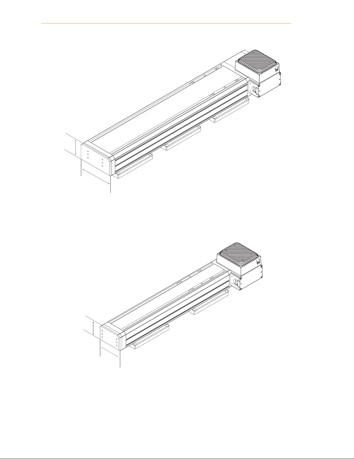
Figure 1-1. L18 Linear Module with MB-10 Amplifier . . . . . . . . . . . . . . . . . . . . . . . . . . . . . . . . . . . . . . . . 16
Figure 1-2. L12 Linear Module with MB-10 Amplifier . . . . . . . . . . . . . . . . . . . . . . . . . . . . . . . . . . . . . . . . 16
Figure 1-3. L08 Linear Module with MB-10 Amplifier . . . . . . . . . . . . . . . . . . . . . . . . . . . . . . . . . . . . . . . . 17
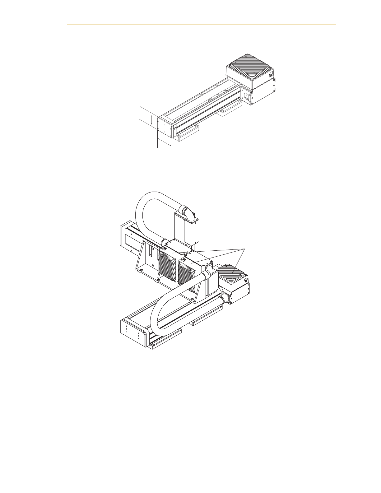
Figure 1-4. Three-Axis System with L18, L12, and L08 Modules . . . . . . . . . . . . . . . . . . . . . . . . . . . . . . . 17
Figure 1-5. Adept SmartController CX . . . . . . . . . . . . . . . . . . . . . . . . . . . . . . . . . . . . . . . . . . . . . . . . . . . 18
Figure 1-6. PDU3 . . . . . . . . . . . . . . . . . . . . . . . . . . . . . . . . . . . . . . . . . . . . . . . . . . . . . . . . . . . . . . . . . . . . . 19
Figure 3-1. L18 Module without Brake, Shown at End of Stroke . . . . . . . . . . . . . . . . . . . . . . . . . . . . . . 45
Figure 3-2. L18 Module with Brake, Shown at End of Stroke . . . . . . . . . . . . . . . . . . . . . . . . . . . . . . . . . 45
Figure 3-3. L12 Module without Brake, Shown at End of Stroke . . . . . . . . . . . . . . . . . . . . . . . . . . . . . . 46
Figure 3-4. L12 Module with Brake, Shown at End of Stroke . . . . . . . . . . . . . . . . . . . . . . . . . . . . . . . . . 46
Figure 3-5. L08 Module with Brake (Left) and without Brake (Right) . . . . . . . . . . . . . . . . . . . . . . . . . . 46
Figure 3-6. Left- and Right-Hand Orientation Example . . . . . . . . . . . . . . . . . . . . . . . . . . . . . . . . . . . . . 47
Figure 3-7. L18 Module with In-line Motor . . . . . . . . . . . . . . . . . . . . . . . . . . . . . . . . . . . . . . . . . . . . . . . . 48
Figure 3-8. L18 Module with Left-Side Motor . . . . . . . . . . . . . . . . . . . . . . . . . . . . . . . . . . . . . . . . . . . . . . 48
Figure 3-9. L18 Module with Right-Side Motor . . . . . . . . . . . . . . . . . . . . . . . . . . . . . . . . . . . . . . . . . . . . 49
Figure 3-10. L18 Module with Bottom-Mount Motor . . . . . . . . . . . . . . . . . . . . . . . . . . . . . . . . . . . . . . . . 49
Figure 3-11. In-Line Motor, Left Harness Exit Locations . . . . . . . . . . . . . . . . . . . . . . . . . . . . . . . . . . . . . . 50
Figure 3-12. In-Line Motor, Right Harness Exit Locations . . . . . . . . . . . . . . . . . . . . . . . . . . . . . . . . . . . . 50
Figure 3-13. Left-Side Motor Mount, Harness Exit Locations . . . . . . . . . . . . . . . . . . . . . . . . . . . . . . . . . 51
Figure 3-14. Right-Side Motor Mount, Harness Exit Locations . . . . . . . . . . . . . . . . . . . . . . . . . . . . . . . . 51
Figure 3-15. L18 Descriptor Number Example . . . . . . . . . . . . . . . . . . . . . . . . . . . . . . . . . . . . . . . . . . . . . 52
Figure 3-16. L18 Module Descriptor Key, Part 1 of 2 . . . . . . . . . . . . . . . . . . . . . . . . . . . . . . . . . . . . . . . . 53
Figure 3-17. L18 Module Descriptor Key, Part 2 of 2 . . . . . . . . . . . . . . . . . . . . . . . . . . . . . . . . . . . . . . . . 54
Figure 3-18. L12 Descriptor Number Key, Part 1 of 2 . . . . . . . . . . . . . . . . . . . . . . . . . . . . . . . . . . . . . . . 55
Figure 3-19. L12 Descriptor Number Key, Part 2 of 2 . . . . . . . . . . . . . . . . . . . . . . . . . . . . . . . . . . . . . . . 56
Figure 3-20. L08 Descriptor Number Key, Part 1 of 2 . . . . . . . . . . . . . . . . . . . . . . . . . . . . . . . . . . . . . . . 57
Figure 3-21. L08 Module Descriptor Key, Part 2 of 2 . . . . . . . . . . . . . . . . . . . . . . . . . . . . . . . . . . . . . . . . 58
Figure 3-22. Gantry (LG6) Module . . . . . . . . . . . . . . . . . . . . . . . . . . . . . . . . . . . . . . . . . . . . . . . . . . . . . . 59
Figure 3-23. LG6 (Gantry) Descriptor Number Example . . . . . . . . . . . . . . . . . . . . . . . . . . . . . . . . . . . . 59
Figure 3-24. LG6 (Gantry) Descriptor Number Key . . . . . . . . . . . . . . . . . . . . . . . . . . . . . . . . . . . . . . . . . 60
Figure 4-1. LT1 (Theta) Module with User Flange . . . . . . . . . . . . . . . . . . . . . . . . . . . . . . . . . . . . . . . . . . 63
Figure 4-2. LT1 (Theta) Module with Standard Shaft/Range of Motion . . . . . . . . . . . . . . . . . . . . . . . . 64
Figure 4-3. LT1 (Theta) Module Descriptor Number Example . . . . . . . . . . . . . . . . . . . . . . . . . . . . . . . . 64
Figure 4-4. LT1 (Theta) Module Descriptor Key . . . . . . . . . . . . . . . . . . . . . . . . . . . . . . . . . . . . . . . . . . . . 65
Figure 5-1. Module System Descriptor Number Example . . . . . . . . . . . . . . . . . . . . . . . . . . . . . . . . . . . 68
Figure 5-2. Module System Descriptor Number Key, Part 1 of 2 . . . . . . . . . . . . . . . . . . . . . . . . . . . . . . 69
Figure 5-3. Module System Descriptor Number Key, Part 2 of 2 . . . . . . . . . . . . . . . . . . . . . . . . . . . . . . 70
Figure 5-4. IO Blox Options in Module System Descriptor Number . . . . . . . . . . . . . . . . . . . . . . . . . . . . 71
Figure 5-5. Three-Axis System with MB-10 Amplifiers Identified . . . . . . . . . . . . . . . . . . . . . . . . . . . . . . . 71
Figure 5-6. Configuration Options in Module System Descriptor Number . . . . . . . . . . . . . . . . . . . . . . 72
Figure 5-7. S2000 System with Mounting Feet . . . . . . . . . . . . . . . . . . . . . . . . . . . . . . . . . . . . . . . . . . . . . 73
Figure 5-8. S2000 System (with Brake) Mounted Vertically . . . . . . . . . . . . . . . . . . . . . . . . . . . . . . . . . . 74
Adept Python Modules User’s Guide, Rev. E 11
Page 12

List of Figures
Figure 5-9. LT1 (Theta) Module Envelope/Mounting Hole Dimensions (Top View) . . . . . . . . . . . . . . . 75
Figure 5-10. LT1 (Theta) Module Envelope/Mounting Hole Dimensions (Side View) . . . . . . . . . . . . . 76
Figure 5-11. LT1 (Theta) Module Envelope/Mounting Hole Dimensions (Bottom View) . . . . . . . . . . . 76
Figure 5-12. LT1 (Theta) Module User Flange Dimensions . . . . . . . . . . . . . . . . . . . . . . . . . . . . . . . . . . . 77
Figure 5-13. D1200 System with Optional Mounting Feet . . . . . . . . . . . . . . . . . . . . . . . . . . . . . . . . . . . 78
Figure 5-14. G1200 System with Optional Mounting Feet . . . . . . . . . . . . . . . . . . . . . . . . . . . . . . . . . . . 79
Figure 5-15. K1200 System . . . . . . . . . . . . . . . . . . . . . . . . . . . . . . . . . . . . . . . . . . . . . . . . . . . . . . . . . . . . . 80
Figure 5-16. X1100 System with Optional Mounting Feet . . . . . . . . . . . . . . . . . . . . . . . . . . . . . . . . . . . . 81
Figure 5-17. Z1200 System . . . . . . . . . . . . . . . . . . . . . . . . . . . . . . . . . . . . . . . . . . . . . . . . . . . . . . . . . . . . . 82
Figure 5-18. P Configuration (P1230 System) . . . . . . . . . . . . . . . . . . . . . . . . . . . . . . . . . . . . . . . . . . . . . . 83
Figure 5-19. Q Configuration (Q1230 System) . . . . . . . . . . . . . . . . . . . . . . . . . . . . . . . . . . . . . . . . . . . . . 84
Figure 5-20. P Configuration with Theta . . . . . . . . . . . . . . . . . . . . . . . . . . . . . . . . . . . . . . . . . . . . . . . . . . 85
Figure 5-21. Q Configuration with Theta . . . . . . . . . . . . . . . . . . . . . . . . . . . . . . . . . . . . . . . . . . . . . . . . . 86
Figure 5-22. Single-Axis Orientation Example . . . . . . . . . . . . . . . . . . . . . . . . . . . . . . . . . . . . . . . . . . . . . 87
Figure 5-23. Standard/Standard Orientation . . . . . . . . . . . . . . . . . . . . . . . . . . . . . . . . . . . . . . . . . . . . . 87
Figure 5-24. Flipped/Standard Orientation . . . . . . . . . . . . . . . . . . . . . . . . . . . . . . . . . . . . . . . . . . . . . . . 88
Figure 5-25. Standard/Rolled Orientation (Rear View) . . . . . . . . . . . . . . . . . . . . . . . . . . . . . . . . . . . . . 88
Figure 5-26. Flipped/Rolled Orientation . . . . . . . . . . . . . . . . . . . . . . . . . . . . . . . . . . . . . . . . . . . . . . . . . . 89
Figure 5-27. Mounting Options in Module System Descriptor Number . . . . . . . . . . . . . . . . . . . . . . . . 90
Figure 5-28. S1000SS13 - Single L18 System with Three Mounting Feet . . . . . . . . . . . . . . . . . . . . . . . . . 91
Figure 5-29. S1000SS00 - Single L18 System without Mounting Feet . . . . . . . . . . . . . . . . . . . . . . . . . . . 91
Figure 5-30. L08 Module with Toe Clamps . . . . . . . . . . . . . . . . . . . . . . . . . . . . . . . . . . . . . . . . . . . . . . . . 92
Figure 5-31. L12 Module with Toe Clamps . . . . . . . . . . . . . . . . . . . . . . . . . . . . . . . . . . . . . . . . . . . . . . . . 92
Figure 5-32. L18 Module with Toe Clamps . . . . . . . . . . . . . . . . . . . . . . . . . . . . . . . . . . . . . . . . . . . . . . . . 93
Figure 5-33. L18 Module with Mounting Feet Dimensions . . . . . . . . . . . . . . . . . . . . . . . . . . . . . . . . . . . 93
Figure 5-34. L12 Module with Mounting Feet Dimensions . . . . . . . . . . . . . . . . . . . . . . . . . . . . . . . . . . . 94
Figure 5-35. L08 Module with Mounting Feet Dimensions . . . . . . . . . . . . . . . . . . . . . . . . . . . . . . . . . . . 94
Figure 5-36. LG6 Module with Mounting Feet Dimensions . . . . . . . . . . . . . . . . . . . . . . . . . . . . . . . . . . . 95
Figure 5-37. L08 Module with Toe Clamp Dimensions . . . . . . . . . . . . . . . . . . . . . . . . . . . . . . . . . . . . . . 95
Figure 5-38. L12 Module with Toe Clamp Dimensions . . . . . . . . . . . . . . . . . . . . . . . . . . . . . . . . . . . . . . 96
Figure 5-39. L18 Module with Toe Clamp Dimensions . . . . . . . . . . . . . . . . . . . . . . . . . . . . . . . . . . . . . . 96
Figure 5-40. Cable Kit Descriptors for a Typical 3-Axis P or Q System . . . . . . . . . . . . . . . . . . . . . . . . . . 97
Figure 5-41. Gantry (LG6) Module Shown with Gantry Mounting Kit . . . . . . . . . . . . . . . . . . . . . . . . . . 98
Figure 5-42. Gantry Key Details . . . . . . . . . . . . . . . . . . . . . . . . . . . . . . . . . . . . . . . . . . . . . . . . . . . . . . . . . 99
Figure 5-43. L12 Gantry Mounting Methods, End and Side . . . . . . . . . . . . . . . . . . . . . . . . . . . . . . . . . . 99
Figure 5-44. Gantry Installation: Parallel Alignment Specs . . . . . . . . . . . . . . . . . . . . . . . . . . . . . . . . . 100
Figure 5-45. Gantry Installation: Lip Seal to Support Bracket Gap Dimensions . . . . . . . . . . . . . . . . . 101
Figure 5-46. Gantry Over-Travel Specifications . . . . . . . . . . . . . . . . . . . . . . . . . . . . . . . . . . . . . . . . . . . 102
Figure 5-47. IO Blox Options in Module System Descriptor Number . . . . . . . . . . . . . . . . . . . . . . . . . . 104
Figure 5-48. Mounting onto an MB-10 Amp . . . . . . . . . . . . . . . . . . . . . . . . . . . . . . . . . . . . . . . . . . . . . 104
Figure 5-49. Mounting onto an L18 Module . . . . . . . . . . . . . . . . . . . . . . . . . . . . . . . . . . . . . . . . . . . . . 105
Figure 5-50. Mounting onto a Module T-Slot . . . . . . . . . . . . . . . . . . . . . . . . . . . . . . . . . . . . . . . . . . . . . 105
Figure 5-51. Mounting onto a Two-Axis System . . . . . . . . . . . . . . . . . . . . . . . . . . . . . . . . . . . . . . . . . . . 106
Figure 5-52. Mounting onto a Three-Axis System . . . . . . . . . . . . . . . . . . . . . . . . . . . . . . . . . . . . . . . . . 107
Figure 5-53. Cabling/Plumbing Options in Module System Descriptor Number . . . . . . . . . . . . . . . . 107
Figure 6-1. Recommended Lifting Technique for Python System . . . . . . . . . . . . . . . . . . . . . . . . . . . . 109
12 Adept Python Modules User’s Guide, Rev. E
Page 13

List of Figures
Figure 6-2. Typical Three-Axis System on Shipping Pallet with Contents Labelled . . . . . . . . . . . . . . 111
Figure 6-3. Removing Shipping Screws from Axis 3 . . . . . . . . . . . . . . . . . . . . . . . . . . . . . . . . . . . . . . . 111
Figure 6-4. Installing Axis 3 on Axis 2 . . . . . . . . . . . . . . . . . . . . . . . . . . . . . . . . . . . . . . . . . . . . . . . . . . . . 112
Figure 6-5. Removing Shipping Screws from Axis 2 . . . . . . . . . . . . . . . . . . . . . . . . . . . . . . . . . . . . . . . 112
Figure 6-6. Removing Shipping Screws from Axis 1 . . . . . . . . . . . . . . . . . . . . . . . . . . . . . . . . . . . . . . . 113
Figure 6-7. Lifting a Python System Using a Hoist and Slings . . . . . . . . . . . . . . . . . . . . . . . . . . . . . . . . 113
Figure 6-8. Example Cleanroom Module System . . . . . . . . . . . . . . . . . . . . . . . . . . . . . . . . . . . . . . . . . 115
Figure 7-1. System Cable Diagram . . . . . . . . . . . . . . . . . . . . . . . . . . . . . . . . . . . . . . . . . . . . . . . . . . . . 118
Figure 8-1. Adept PDU3 . . . . . . . . . . . . . . . . . . . . . . . . . . . . . . . . . . . . . . . . . . . . . . . . . . . . . . . . . . . . . . 121
Figure 8-2. Typical Single-Phase 200-240 VAC Connection . . . . . . . . . . . . . . . . . . . . . . . . . . . . . . . . 123
Figure 8-3. Typical Three-Phase 200-240 VAC Connection . . . . . . . . . . . . . . . . . . . . . . . . . . . . . . . . . 123
Figure 8-4. Typical Three-Phase 380-415 VAC Connection . . . . . . . . . . . . . . . . . . . . . . . . . . . . . . . . . 123
Figure 8-5. PDU3 with Mounting Brackets Installed . . . . . . . . . . . . . . . . . . . . . . . . . . . . . . . . . . . . . . . 126
Figure 8-6. PDU3 Dimensions . . . . . . . . . . . . . . . . . . . . . . . . . . . . . . . . . . . . . . . . . . . . . . . . . . . . . . . . . . 127
Figure 8-7. Mounting Bracket Dimensions . . . . . . . . . . . . . . . . . . . . . . . . . . . . . . . . . . . . . . . . . . . . . . . 128
Figure 8-8. E-Stop Circuit Diagram for PDU3 . . . . . . . . . . . . . . . . . . . . . . . . . . . . . . . . . . . . . . . . . . . . . 130
Figure 9-1. Adept MB-10 Amplifier . . . . . . . . . . . . . . . . . . . . . . . . . . . . . . . . . . . . . . . . . . . . . . . . . . . . . 133
Figure 9-2. Connector Locations on MB-10 Amp . . . . . . . . . . . . . . . . . . . . . . . . . . . . . . . . . . . . . . . . . 135
Figure 9-3. Attaching the AC Power and Ground Cables . . . . . . . . . . . . . . . . . . . . . . . . . . . . . . . . . 136
Figure 9-4. EEPROM Device on T-Bracket . . . . . . . . . . . . . . . . . . . . . . . . . . . . . . . . . . . . . . . . . . . . . . . 137
Figure 10-1. DC_SETUP Program Main Screen . . . . . . . . . . . . . . . . . . . . . . . . . . . . . . . . . . . . . . . . . . . 146
Figure 10-2. DC_SETUP Program Setup Screen . . . . . . . . . . . . . . . . . . . . . . . . . . . . . . . . . . . . . . . . . . . 147
Figure 10-3. DC_SETUP Program Node to Robot/Motor Map Screen . . . . . . . . . . . . . . . . . . . . . . . . 147
Figure 10-4. DC_SETUP Program Current Configuration Screen . . . . . . . . . . . . . . . . . . . . . . . . . . . . . 148
Figure 10-5. Calibration Setup Screen . . . . . . . . . . . . . . . . . . . . . . . . . . . . . . . . . . . . . . . . . . . . . . . . . . 149
Figure 11-1. MB-10 Internal Battery and Retaining Clip . . . . . . . . . . . . . . . . . . . . . . . . . . . . . . . . . . . . 155
Figure 11-2. MB-10 Internal Battery Location . . . . . . . . . . . . . . . . . . . . . . . . . . . . . . . . . . . . . . . . . . . . 156
Figure 11-3. Encoder Battery . . . . . . . . . . . . . . . . . . . . . . . . . . . . . . . . . . . . . . . . . . . . . . . . . . . . . . . . . 156
Figure 11-4. Replacement Cable Assembly Installed in Module . . . . . . . . . . . . . . . . . . . . . . . . . . . . 158
Figure 12-1. System Installation with Two Linear Module Robots Daisy-Chained . . . . . . . . . . . . . . . 162
Figure 12-2. System Installation with Three Linear Module Robots and Two PDUs . . . . . . . . . . . . . . 163
Figure 12-3. Three Linear Module Robots, Two PDUs, and a Cobra s600 with Vision . . . . . . . . . . . . 164
Adept Python Modules User’s Guide, Rev. E 13
Page 14

Page 15

1.1 Product Description
Adept Python Modules
The Adept Python Linear Modules product line consists of precision ball-screw driven
modules that function as single-axis mechanisms, and can also be combined into
numerous two-, three-, and four-axis configurations. Each linear module is available in
different lengths (see Table 1-1) and motor mounting configurations. The Theta module
adds a rotational axis to a Python system, providing additional handling options. You can
find drawings for the multiple axis configurations in Chapter 5.
Most module configurations are shipped fully assembled, so the user only needs to
connect the controller and any peripherals. This manual describes the different module
and system types, and covers the basic steps of installing a typical system. Refer to
Table 1-2 on page 22 for a list of manuals that provide additional information on your
Adept system.
Introduction 1
Table 1-1. Adept Python Modules
Module Type Width Height Available Lengths
L18 185 mm 93 mm 300 to 2000 mm
L12 125 mm 83 mm 200 to 1500 mm
L08 85 mm 68 mm 100 to 800 mm
LT1 90 mm 65 mm With User Flange = 240 mm
Without Flange = 230 mm
MotionBlox-10 Servo Controller and Amplifier
Each module axis is controlled and powered by its own on-board servo controller and
amplifier, called a MotionBlox-10 (MB-10). Each MB-10 is linked via the IEEE 1394
high-speed serial communication protocol to the Adept SmartController.
Adept Python Modules User’s Guide, Rev. E 15
Page 16
Chapter 1 - Introduction
93 mm
L18 Module with
MotionBlox-10 Amp
83 mm
185 mm
Figure 1-1. L18 Linear Module with MB-10 Amplifier
L12 Module with
MotionBlox-10 Amp
125 mm
Figure 1-2. L12 Linear Module with MB-10 Amplifier
16 Adept Python Modules User’s Guide, Rev. E
Page 17
L08 Module with
MotionBlox-10 Amp
68 mm
85 mm
Figure 1-3. L08 Linear Module with MB-10 Amplifier
Product Description
Daisy-chained set of
MB-10 amplifiers, one
for each module
Figure 1-4. Three-Axis System with L18, L12, and L08 Modules
Adept Python Modules User’s Guide, Rev. E 17
Page 18
Chapter 1 - Introduction
Special and Custom Orders
Special orders consist of any unique module or system configuration not outlined in this
manual, or supported by the Adept 3D Modules configuration tool on our website.
Custom orders consist of any order containing a custom module or module system. These
orders may not be fully assembled at the factory.
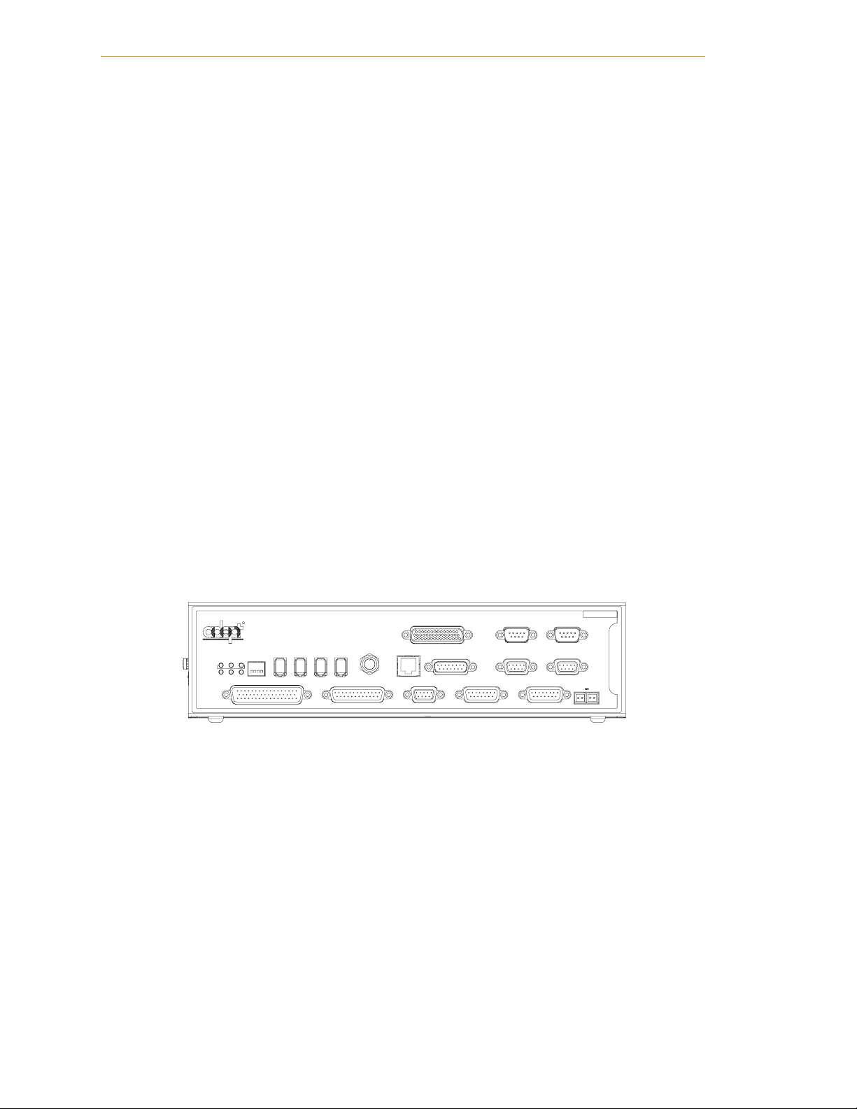
Adept SmartController CX
The SmartController CX is the foundation of Adept’s family of high-performance
distributed motion and vision controllers. The SmartController CX is designed for use
with:
• Adept Cobra s-series robots
• Adept Viper s-series robots
•Adept Python Modules
• Adept Servo Kit Systems
•Adept sMI6 (SmartMotion)
• Adept Quattro robots
The SmartController CX supports an integrated vision option and a conveyor tracking
option. It offers scalability and support for IEEE 1394-based digital I/O and general
motion expansion modules. The IEEE 1394 interface is the backbone of Adept SmartServo,
Adept's distributed controls architecture supporting Adept products. The controller also
includes Fast Ethernet and DeviceNet.
RS-422/485
RS-232-2
*S/N 3562-XXXXX*
XDC1 XDC2
24V 5A
-+ -+
SmartController CX
OK
SF ES HD
123
R
LANHPE
1234
SmartServo IEEE-1394
1.1 1.2 2.1 2.2
SW1
ON
OFF
XDIO
XUSR
Device Net
Eth 10/100
XSYS
CAMERA
BELT ENCODER
RS-232/TERM
RS-232-1
XFP
XMCP
Figure 1-5. Adept SmartController CX
18 Adept Python Modules User’s Guide, Rev. E
Page 19
Product Description
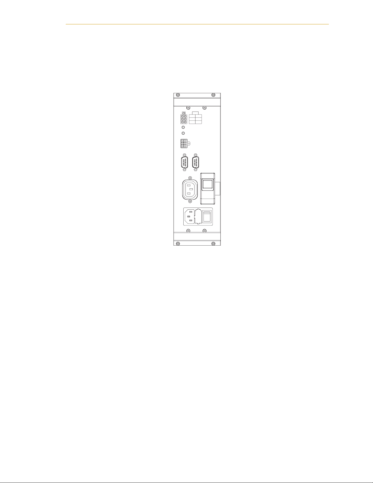
Power Distribution Unit (PDU3)
The Power Distribution Unit (PDU3) is a safety device that provides Category-3 E-Stop
functionality, per EN 954. The PDU3 also provides surge protection, power filtering, and
DC power for the MB-10 and optional IO Blox devices.
PDU3
24V
AMP
AUX
CH1 CH2
ES2
ES1
AMP DC RESET
AUX DC RESET
XDCS
1
AC
PWR
AMP
AC
PWR
IN
2
XSLV1/
XSLV2
Figure 1-6. PDU3
B
C
R
I
E
R
A
C
K
U
E
I
R
T
Adept Python Modules User’s Guide, Rev. E 19
Page 20

Chapter 1 - Introduction
1.2 Overview of Typical System Installation
This section provides an overview of the installation process for a typical Adept Python
modules system using an Adept SmartController.
Installing Adept Python Modules
1. Unpack your system and verify that you have everything required.
2. Install the modules onto your work surface (see Chapter 6 for information).
3. Connect these cables:
a. IEEE 1394 cable from MB-10 #1 to SmartController
b. Switched AC power cable from MB-10 #1 to PDU3
c. 24 VDC cable from MB-10 #1 to PDU3
4. To install an optional IO Blox device, see the Adept IO Blox User’s Guide.
Installing the SmartController
NOTE: Refer to the Adept SmartController User’s Guide for detailed
instructions on installing the controller.
1. Mount the controller chassis in the workcell. There are several different mounting
choices. See page 117.
2. Connect 24 VDC power to the SmartController.
3. Connect a ground wire to the SmartController.
Installing Peripherals and Options
1. Install the PDU3 in the workcell. See Section 8.2 on page 122.
2. Connect AC power to the PDU3. See Section 8.3 on page 123.
3. Mount the Adept Front Panel.
It must be outside of the workcell. See the Adept SmartController User’s Guide
for information on using the Front Panel.
4. Connect the Front Panel to the SmartController. See Section 7.4 on page 119.
5. Connect the optional T2 pendant to the SmartController. See Section 7.5 on page
119.
6. Install the User Interface. See Section 7.6 on page 120. There are two choices:
• AdeptWindows PC software, running on the user-supplied PC
• Optional Adept DeskTop software, running on the user-supplied PC
20 Adept Python Modules User’s Guide, Rev. E
Page 21

7. Refer to the Operation chapter in the Adept SmartController User’s Guide for
information on installing customer-supplied equipment and safety circuits,
including:
• Emergency Stop circuits
• Remote Manual Mode control
• Remote High Power control
• Connecting user-supplied serial and digital I/O equipment
Turning On the System
1. Refer to Chapter 10 to perform system installation verification.
2. After the installation has been verified for all safety regulations, turn on DC
power to the controller and AC power to the PDU.
3. See Section 10.4 on page 145 for the software configuration process.
Manufacturer’s Declaration
1.3 Manufacturer’s Declaration
The Manufacturer’s Declaration of Incorporation and Conformity for Adept Python
modules systems can be found on the Adept website, in the Download Center of the
Support section.
http://www.adept.com/support/downloads_disclaimer.asp
In the Download Types search box, select Regulatory Certificates to find the document,
which you can then download.
1.4 How Can I Get Help?
Refer to the How to Get Help Resource Guide (Adept P/N 00961-00700) for details on
getting assistance with your Adept software and hardware.
Additionally, you can access information sources on Adept’s corporate website:
http://www.adept.com
Adept Python Modules User’s Guide, Rev. E 21
Page 22

Chapter 1 - Introduction
1.5 Related Manuals
This manual covers the installation of a SmartContoller-based Adept Python Modules
system. There are additional manuals that cover programming the system, reconfiguring
installed components, and adding other optional components. See Table 1-2. These
manuals are available on the Adept Document Library on CD-ROM provided with each
system.
Manual Title Description
Table 1-2. Related Manuals
Adept SmartController
User’s Guide
Adept T2 Pendant User’s
Guide
Adept IO Blox User’s Guide Describes the IO Blox product.
AdeptWindows Installation
Guide and AdeptWindows
Online Help
Instructions for Adept
Utility Programs
V+ Operating System User’s
Guide
V+ Language User’s Guide Describes the V
Contains complete information on the installation and operation
of the Adept SmartController and the optional sDIO products.
Describes the T2 Pendant product.
Describes complex network installations, installation and use of
NFS server software, the AdeptWindows Offline Editor, and the
AdeptWindows DDE software.
Describes the utility programs used for advanced system
configurations, system upgrades, file copying, and other system
configuration procedures.
Describes the V
operations, monitor commands, and monitor command
programs.
control system.
+
operating system, including disk file
+
language and programming of an Adept
Adept Document Library
In addition to the Adept Document Library on CD-ROM, you can find Adept product
documentation on the Adept website in the Document Library area. The Document
Library search engine allows you to locate information on a specific topic. Additionally,
the Document Menu provides a list of available product documentation.
To access the Adept Document Library, type the following URL into your browser:
http://www.adept.com/Main/KE/DATA/adept_search.htm
or, select the Document Library link on the Home page of the Adept website.
22 Adept Python Modules User’s Guide, Rev. E
Page 23
Safety 2
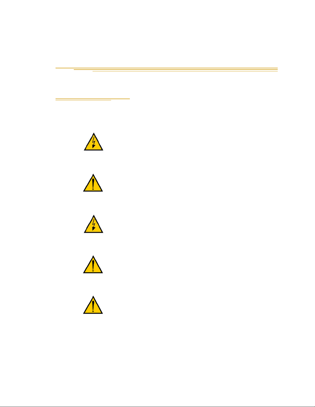
2.1 Dangers, Warnings, Cautions, and Notes
There are six levels of special alert notation used in this manual. In descending order of
importance, they are:
DANGER: This indicates an imminently hazardous
electrical situation which, if not avoided, will result in
death or serious injury.
DANGER: This indicates an imminently hazardous
situation which, if not avoided, will result in death or
serious injury.
WARN IN G: This indicates a potentially hazardous
electrical situation which, if not avoided, could result in
injury or major damage to the equipment.
WARN IN G: This indicates a potentially hazardous
situation which, if not avoided, could result in injury or
major damage to the equipment.
CAUTION: This indicates a situation which, if not avoided,
could result in damage to the equipment.
NOTE: This provides supplementary information, emphasizes a point or
procedure, or gives a tip for easier operation.
Adept Python Modules User’s Guide, Rev. E 23
Page 24

Chapter 2 - Safety
2.2 Intended Use of the Modules
The installation and use of Adept products must comply with all safety instructions and
warnings in this manual. Installation and use must also comply with all applicable local
and national requirements and safety standards (see Section 2.7 on page 31).
Adept Python Modules are intended for use in parts assembly and material handling for a
variety of payloads, depending on the specific configuration.
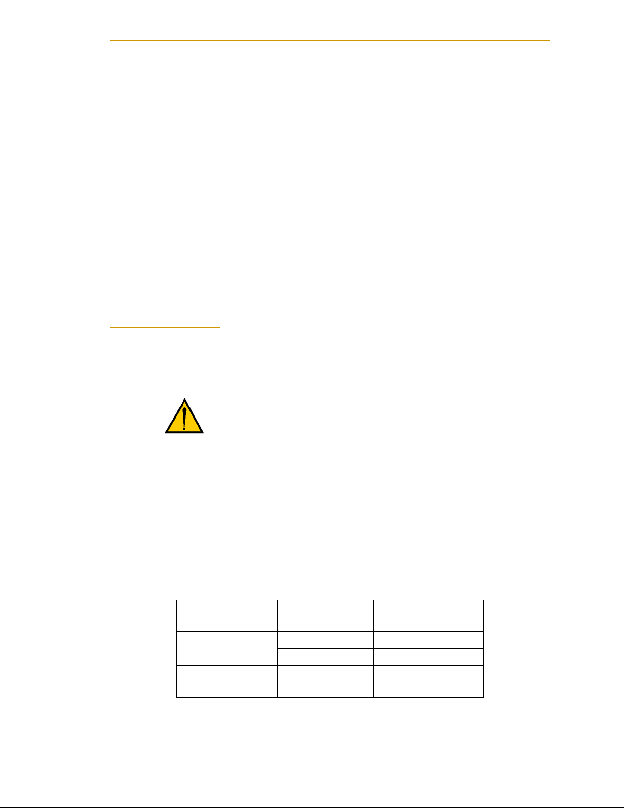
WARN IN G: For safety reasons, it is prohibited to make
certain modifications to Adept robots (see Section 2.5 on
page 30).
The SmartController is a component subassembly of a complete industrial automation
system. The SmartController must be installed inside a suitable enclosure. The
SmartController and modules must not come into contact with liquids.
The Adept equipment is not intended for use in any of the following situations:
• In hazardous (explosive) atmospheres
• In mobile, portable, marine, or aircraft systems
• In life-support systems
• In residential installations
• In situations where the Adept equipment will be washed down or subject to
extremes of heat or humidity.
Non-intended use of an Adept Python Modules system can:
• Cause injury to personnel
• Damage the robot or other equipment
• Reduce system reliability and performance
All persons that install, commission, operate, or maintain the robot must:
• Have the necessary qualifications
• Read and follow exactly the instructions in the documentation
WARN IN G: The instructions for operation, installation,
and maintenance given in the documentation must be
strictly observed.
If there is any doubt concerning the application, ask Adept to determine if it is an
intended use or not.
24 Adept Python Modules User’s Guide, Rev. E
Page 25

Risk Assessment
2.3 Risk Assessment
Without special safeguards in its control system, Adept Python Modules could inflict
serious injury on an Operator working within its work envelope. Safety standards in
many countries require appropriate safety equipment to be installed as part of the system.
Table 2-1 lists some of the safety standards that affect industrial robots. It is not a
complete list. You must comply with all applicable local and national standards for the
location where the robot will be installed.
Table 2-1. Partial List of Robot and Machinery Safety Standards
International USA Canada Europe Title of Standard
ISO 10218 EN 775 Manipulating Industrial Robots -
Safety
ANSI/RIA
R15.06
Adept has performed a Risk Assessment for this product, based on the intended
applications of the robot. The conclusions are summarized in the following sections.
CAN/CSAZ434-94
Industrial Robots and Robot Systems
- Safety Requirements
EN 292-2 Safety of Machinery - Basic
Concepts, General Principles for
Design
EN 954-1 Safety Related Parts of Control
Systems - General Principles for
Design
EN 1050 Safety of Machinery - Risk
Assessment
Exposure
When High Power is on, all personnel must be kept out of the robot work envelope by
interlocked perimeter barriers. The only permitted exception is for teaching the robot in
Manual Mode by a skilled programmer (see Section 2.11 on page 33), who must wear
safety equipment (see Section 2.12 on page 33) and carry the T2 pendant. Therefore,
exposure of personnel to hazards related to the robot is limited (seldom and/or short
exposure time).
Severity of Injury
Provided that skilled personnel who enter the modules robot work envelope are wearing
protective headgear, eyeglasses, and safety shoes, it is likely that any injuries caused by
the robot would be slight (normally reversible).
Adept Python Modules User’s Guide, Rev. E 25
Page 26

Chapter 2 - Safety
Avoidance
Due to the module’s size and speed capability, it is likely that such personnel could avoid
being hit by the robot even in a high-acceleration, runaway failure condition. The
programmer must carry the T2 pendant when inside the work envelope, as the T2
pendant provides both E-Stop and Enabling switch functions.
For normal operation, AUTO mode, user-supplied interlocked guarding must be installed
to prevent any person entering the workcell while High Power is on.
DANGER: The Adept-supplied system components
provide Category 3 Emergency Stop functionality and
Category 1 protection during TeachMode operation, as
defined by EN 954. The robot system must be installed
with user-supplied interlock barriers. The interlocked
barrier should interrupt the AC supply to the system in
the event of personnel attempting to enter the workcell
when High Power is enabled, except for Teaching in
Manual mode. Failure to install suitable guarding could
result in injury or death.
The E-stop CIRCUIT is "category 3" as defined by EN 954 (dual channel: redundant,
diverse, and control-reliable).
Activating the E-stop system causes a Category 0, Uncontrolled stop, as defined by
NFPA79.
The E-stop circuit is Dual Channel (redundant, diverse, and control reliable).
The Risk Assessment for teaching this product depends on the application. In many
applications, the programmer will need to enter the robot workcell while High Power is
enabled to teach the robot. Other applications can be designed so that the programmer
does not have to enter the work envelope while High Power is on. Examples of alternative
methods of programming include:
1. Programming from outside the safety barrier.
2. Programming with High Power off (using the brake release button when
required).
3. Copying a program from another (master) robot.
4. Off-line or CAD programming.
Control System Behavior Category
The following paragraphs relate to the requirements of European (EU/EEA) directives for
Machinery, Electric Safety, and Electromagnetic Compatibility (EMC).
26 Adept Python Modules User’s Guide, Rev. E
Page 27
Precautions and Required Safeguards
In situations with low exposure consideration factors, European Standard EN 1050
specifies use of a Category 1 Control System per EN 954. EN 954 defines a Category 1
Control System as one that employs Category B components designed to withstand
environmental influences, such as voltage, current, temperature, EMI, and well-tried
safety principles. The standard SmartController control system described in this user’s
guide employs hardware components in its safety system that meet or exceed the
requirements of the EU Machinery Directive and Low Voltage Directive.
Furthermore, the standard control system is fully hardened to all EMI influences per the
EU EMC Directive and meets all functional requirements of ISO 10218 (EN 775)
Manipulating Robots Safety. In addition, a software-based reduced speed and maximum
current limit provided to the motor by the amplifier have been incorporated to limit speed
and impact forces on the Operator and production tooling when the robot is operated in
Manual mode.
In consideration of the above, the standard Adept SmartController Control System meets
or exceeds the requirements imposed by the EN 954 specified Category 1 level of safety.
2.4 Precautions and Required Safeguards
This manual must be read by all personnel who install, operate, or maintain Adept
systems, or who work within or near the workcell.
WARN IN G: Adept Technology strictly prohibits
installation, commissioning, or operation of an Adept
robot without adequate safeguards according to
applicable local and national standards. Installations in EU
and EEA countries must comply with EN 775/ISO 10218,
especially sections 5, 6, EN 292-2, EN 954-1, and
EN 60204-1, especially section 13.
Maximum Thrust
Adept Python Modules systems include computer-controlled mechanisms that are
capable of exerting considerable force. Like all robot and motion systems, and most
industrial equipment, they must be treated with respect by the user and the operator (see
Table 2-2 and Table 2-3).
Table 2-2. Maximum Thrust (at slider)
Module Type
Lead type,
mm/rev
[N], Instantaneous
a
Maximum thrust
L18 and L12 10 2280
20 1140
L08 10 850
20 430
Adept Python Modules User’s Guide, Rev. E 27
Page 28

Chapter 2 - Safety
a
Safety Barriers
Safety barriers must be an integral part of robot workcell design. Adept systems are
computer-controlled and may activate remote devices under program control at times or
along paths not anticipated by personnel. It is critical that safeguards be in place to
prevent personnel from entering the workcell whenever equipment power is present.
The robot system integrator, or end user, must ensure that adequate safeguards, safety
barriers, light curtains, safety gates, safety floor mats, etc., will be installed. The robot
workcell must be designed according to the applicable local and national standards (see
Section 2.7 on page 31).
The safe distance to the robot depends on the height of the safety fence. The height and
the distance of the safety fence from the robot must ensure that personnel cannot reach the
danger zone of the robot (see Section 2.7 on page 31).
The Adept control system has features that aid the user in constructing system
safeguards, including customer emergency stop circuitry and digital input and output
lines. The emergency power-off circuitry is capable of switching external power systems,
and can be interfaced to the appropriate user-supplied safeguards.
See module product specifications for maximum rated thrust
that can be applied repeatedly in an application. The values
listed in the table above are for safety considerations.
Impact and Trapping Points
The modules are capable of moving at high speeds. If a person is struck by a robot
(impacted) or trapped (pinched), death or serious injury could occur. System
configuration, joint speed, joint orientation, and attached payload all contribute to the
total amount of energy available to cause injury.
Hazards From Expelling a Part or Attached Tooling
The maximum joint tip speeds that can be achieved by Adept Python Modules in a
runaway situation are listed in Table 2-3. Any tooling, fixtures, end-effectors, etc.,
mounted to the module must be attached by sufficient means to resist being expelled from
the module. Additionally, any payload must be held by the end-effector in a manner that
prevents the payload from being expelled accidentally.
Table 2-3. Maximum Linear Modules Joint Velocities in Runaway Situations
Module Type
Lead type,
mm/rev
Max linear speed
(mm/s)
a
L18 10 979
20 1940
L12 10 979
20 1940
L08 10 1170
20 2340
a
These velocities can occur only in a runaway or mechanical
failure situation. These are not performance specifications.
28 Adept Python Modules User’s Guide, Rev. E
Page 29

Precautions and Required Safeguards
The safety fence or barrier constructed around the robot must be designed to withstand
the impact of any item expelled accidentally from the robot. Projectile energy can be
calculated using the formula E = 1/2mv
2
.
Additional Safety Information
The standards and regulations listed in this manual contain additional guidelines for
robot system installation, safeguarding, maintenance, testing, start-up, and operator
training. Table 2-4 on page 29 lists some sources for the various standards.
.
Table 2-4. Sources for International Standards and Directives
SEMI International Standards
3081 Zanker Road
San Jose, CA 95134
USA
Phone: 1.408.943.6900
Fax: 1.408.428.9600
http://www.semi.org/
BSI Group (British Standards)
389 Chiswick High Road
London W4 4AL
United Kingdom
Phone +44 (0)20 8996 9000
Fax +44 (0)20 8996 7400
http://www.bsi-global.com
DIN, Deutsches Institut für Normung e.V.
German Institute for Standardization
Burggrafenstrasse 6
10787 Berlin
Germany
Phone.: +49 30 2601-0
Fax: +49 30 2601-1231
American National Standards Institute (ANSI)
11 West 42nd Street, 13th Floor
New York, NY 10036
USA
Phone 212-642-4900
Fax 212-398-0023
http://www.ansi.org
Document Center, Inc.
1504 Industrial Way, Unit 9
Belmont, CA 94002
USA
Phone 415-591-7600
Fax 415-591-7617
http://www.document-center.com
Global Engineering Documents
15 Inverness Way East
Englewood, CO 80112
USA
Phone 800-854-7179
Fax 303-397-2740
http://global.ihs.com
http://www.din.de
http://www2.beuth.de/ (publishing)
IEC, International Electrotechnical Commission
Rue de Varembe 3
PO Box 131
CH-1211 Geneva 20
Switzerland
Phone 41 22 919-0211
Fax 41 22 919-0300
http://www.iec.ch
Adept Python Modules User’s Guide, Rev. E 29
Robotic Industries Association (RIA)
900 Victors Way
PO Box 3724
Ann Arbor, MI 48106
USA
Phone 313-994-6088
Fax 313-994-3338
http://www.robotics.org
Page 30

Chapter 2 - Safety
Table 2-4. Sources for International Standards and Directives (Continued)
Underwriters Laboratories Inc.
333 Pfingsten Road
Northbrook, IL 60062-2096 USA
Phone: +1-847-272-8800
Fax: +1-847-272-8129
http://www.ul.com/info/
2.5 Equipment Modifications
It is sometimes necessary to modify the robot in order to successfully integrate it into a
workcell. Unfortunately, many seemingly simple modifications can either cause a robot
failure or reduce the robot’s performance, reliability, or lifetime. The following
information is provided as a guideline to modifications.
Acceptable Modifications
In general, the following modifications will not cause problems, but may affect
performance:
• Attaching tooling, utility boxes, solenoid packs, vacuum pumps, screwdrivers,
cameras, lighting, etc., to a module.
• Attaching hoses, pneumatic lines, or cables to a module. These should be designed
so they do not restrict robot motion or cause robot motion errors. T-slots and
threaded holes are provided on each module for the purpose of mounting user
equipment. T-slots accept a standard M4 square nut (DIN 562).
Unacceptable Modifications
The following modifications may damage the module, reduce system safety and
reliability, or shorten the life of the module.
CAUTION: Making any of the modifications outlined
below will void the warranty of any components that
Adept determines were damaged due to the modification.
You must contact Adept Customer Service if you are
considering any of the following modifications.
• Modifying any of the module harnesses or module-to-controller cables.
• Modifying any module access covers or drive system components.
• Modifying, including drilling or cutting, any module extrusion.
• Modifying any module or MB-10 electrical component or printed-circuit board.
• Routing additional hoses, air lines, or wires through the module.
• Modifications that compromise EMC performance, including shielding.
30 Adept Python Modules User’s Guide, Rev. E
Page 31

2.6 Transport
Always use adequate equipment to transport and lift Adept products.
Encoder Battery Life
The servo motors in Adept Python modules with MB-10 amplifiers have a serial absolute
encoder. Each module is calibrated before shipment. An external encoder backup battery
is shipped with each module, and is located inside the motor cover. The battery allows the
encoder to retain the calibration data for 10 years of use in this application. The MB-10
amplifier has its own internal battery, which is also rated for 10 years. The encoder does
not receive any power from the MB-10 amplifier’s battery. Therefore, leaving the encoder
connected to the MB-10 during transport or power-off periods will not drain the MB-10
battery. Likewise, disconnecting the module from the MB-10 will not affect the absolute
encoder.
Transport
WARN IN G: Never stand under the module while it is
lifted or transported.
CAUTION: Do not disconnect the encoder backup battery
from the motor encoder cable. Doing so may cause loss of
encoder multi-turn data and the user will be required to
recalibrate the system. See Section 11.4 on page 156 for the
procedure to replace the encoder battery.
2.7 Safety Requirements for Additional Equipment
Additional equipment used with modules (grippers, conveyor belts, etc.) must not reduce
the workcell safeguards.
All emergency stop switches must always be accessible.
If the system is to be used in an EU or EEA member country, all components in the system
workcell must comply with the safety requirements in the European Machine Directive
89/392/EEC (and subsequent amendments) and related harmonized European,
international, and national standards. For robot systems, these include: EN 775/ISO
10218, sections 5,6, EN 292-2, EN 954-1, and EN 60204. For safety fences, see EN 294.
In other countries, Adept strongly recommends, in addition to complying with the
applicable local and national regulations, that a similar level of safety be obtained.
In the USA, applicable standards include ANSI/RIA R15.06 and ANSI/UL 1740.
In Canada, applicable standards include CAN/CSA Z434.
Adept Python Modules User’s Guide, Rev. E 31
Page 32

Chapter 2 - Safety
2.8 Sound Emissions
The sound emission level of a module system depends on the commanded speed and
payload. The maximum value is 85 dB, when measured at 1 meter. (This is at maximum
AUTO-mode speed.)
CAUTION: Acoustic emission from this system may be up
to 85 dB (A) under worst-case conditions. Typical values
will be lower, depending on payload, speed, acceleration,
and mounting. Appropriate safety measures should be
taken, such as ear protection and display of a warning
sign.
2.9 Thermal Hazard
WARN IN G: Thermal Hazard!
You can burn yourself. Do not touch the MB-10 cooling
fins shortly after the system has been running at high
ambient temperatures (40°C/104°F) or at fast cycle times
(over 60 cycles per minute). The MB-10 skin/surface
temperature can reach 85°C (185°F).
2.10 Working Areas
Adept Python Modules have a Manual and an Automatic (AUTO) operating mode. While
in Automatic Mode, personnel are not allowed in the workcell.
In Manual mode, operators with additional safety equipment (see Section 2.12 on page
33) are allowed to work in the workcell. For safety reasons the operator should, whenever
possible, stay outside of the work envelope to prevent injury. The maximum speed and
power of the robot is reduced, but it could still cause injury to the operator.
Before performing maintenance in the working envelope of the robot, High Power must
be switched off and the power supply of the robot must be disconnected. After these
precautions, a skilled person is allowed to maintain the robot. See Section 2.11 for the
specifications.
WARN IN G:
Electrical Hazard!
Impact Hazard!
Never remove any safeguarding and never make changes
in the system that will decommission a safeguard.
32 Adept Python Modules User’s Guide, Rev. E
Page 33

2.11 Qualification of Personnel
This manual assumes that all personnel have attended an Adept training course and have
a working knowledge of the system. The user must provide the necessary additional
training for all personnel who will be working with the system.
As noted in this manual, certain procedures should be performed only by skilled or
instructed persons. For a description of the level of qualification, Adept uses the standard
terms:
• Skilled persons have technical knowledge or sufficient experience to enable them
to avoid the dangers, electrical and/or mechanical.
• Instructed persons are adequately advised or supervised by skilled persons to
enable them to avoid the dangers, electrical and/or mechanical.
All personnel must observe sound safety practices during the installation, operation, and
testing of all electrically powered equipment. To avoid injury or damage to equipment,
always remove power by disconnecting the AC power from the source before attempting
any repair or upgrade activity. Use appropriate lockout procedures to reduce the risk of
power being restored by another person while you are working on the system.
Qualification of Personnel
WARN IN G: The user must get confirmation from every
entrusted person before they start working with the robot
that the person:
• Has received the manual
• Has read the manual
• Understands the manual
• Will work in the manner specified by the manual
For vertically oriented modules, always lower the payload to the bottom hardstop before
attempting any repair or upgrade activity.
2.12 Safety Equipment for Operators
Adept advises operators to wear extra safety equipment in the workcell. For safety
reasons, operators must wear the following when they are in the robot workcell:
• Safety glasses
• Protective headgear (hard hats)
•Safety shoes
Install warning signs around the workcell to ensure that anyone working around the
robot system knows they must wear safety equipment.
Adept Python Modules User’s Guide, Rev. E 33
Page 34

Chapter 2 - Safety
2.13 Protection Against Unauthorized Operation
The system must be protected against unauthorized use. Restrict access to the keyboard
and the pendant by locking them in a cabinet or use another adequate method to prevent
access to them.
2.14 Safety Aspects While Performing Maintenance
Only skilled persons with the necessary knowledge about the safety and operating
equipment are allowed to maintain the robot and controller.
WARN IN G: During maintenance and repair, the power to
the SmartController and PDU3 must be turned off.
Unauthorized third parties must be prevented from
turning on power through the use of lockout measures.
2.15 Risks That Cannot Be Avoided
The Adept Python Modules control system implementation has devices that disable High
Power if a system failure occurs. However, certain residual risks or improper situations
could cause hazards. The following situations may result in risks that cannot be avoided:
• Failure of software or electronics that may cause high-speed robot motion in
Manual mode
• Failure of hardware associated with enabling a device or an E-Stop system
2.16 Risks Due to Incorrect Installation or Operation
Certain risks will be present if installation or operation is not performed properly.
• Purposely defeating any aspect of the safety E-Stop system
• Improper installation or programming of the robot system
• Unauthorized use of cables other than those supplied or use of modified
components in the system
• Defeating an interlock so that an operator can enter a workcell with High Power
ON
• Ejection of a work piece (see “Hazards From Expelling a Part or Attached
Tooling” on page 28)
Take precautions to ensure that these situations do not occur.
34 Adept Python Modules User’s Guide, Rev. E
Page 35

What to Do in an Emergency Situation
2.17 What to Do in an Emergency Situation
Press any E-Stop button (a red push-button on a yellow background/field) and then
follow the internal procedures of your company or organization for an emergency
situation. If a fire occurs, use CO
to extinguish the fire.
2
Adept Python Modules User’s Guide, Rev. E 35
Page 36

Page 37

Python Linear Module
Descriptions 3
3.1 Adept Python Linear Modules
Use the Adept 3D Linear Modules Builder section of the Adept website (www.adept.com)
to select, configure, and request a quote for your linear modules. The website and this
chapter provide detailed information about Adept Python linear modules. See Chapter 4
for information about the Adept Python Theta modules.
Single-Axis and Multiple-Axis Configurations
You can order an Adept Python linear module system consisting of a single module,
MB-10 amplifier, and a SmartController CX. Or, multiple modules can be assembled into a
multi-axis system. For systems with an extended-reach Y-axis, or extended payloads, a
gantry support module is also available.
3.2 Linear Module Options
The following are configurable for each linear module:
• L-Series module type - L18, L12, and L08
• Stroke lengths - 100 and 200 mm increments standard
• Ball screw lead - 5, 10, and 20 mm leads standard
•Fail-safe brakes
• Motor mount orientation - in-line, side-, or bottom--mounted
• Harness exit configuration - left or right side
• Module preparation (assembly) - standard or cleanroom
Adept Python Modules User’s Guide, Rev. E 37
Page 38

Chapter 3 - Python Linear Module Descriptions
L-Series Module Types
Three Python L-Series linear module types are available: L18, L12, and L08. All three
module types have similar construction features:
• Rigid aluminum extruded-frame bodies for high stiffness with
precision-machined straightness tolerances
• Dual linear square rails with four preloaded bearings per carriage to maximize
carriage stiffness and assure high moment load capacities
• Precision ground screw, low backlash ball screw drivetrain (rolled screws used on
certain module configurations)
• Maintenance-free operation - all bearing components are lubricated for life
• High-performance AC servo motors with 8 kHz servo update rate and optimized
current loop tuning in amplifier
• Serial absolute encoders with 65,536 counts/rev minimum resolution; no homing
required
•Zero-backlash, high-stiffness shaft couplings
• Extruded covers with integral belt seals to keep dust out and provide IP-20 ingress
protection
• Mounting options including bolt and dowel pin patterns on underside and
extruded T-slots for toe clamp mounting
All external dimension and weight specifications for each module type can be found on
the module specification drawings located on the Adept website. The load ratings for each
module type scale with the frame size and ball screw lead.
Payloads and Moments
For cantilevered or simply-supported applications, the stiffness of the module's main
body extrusion is an important parameter to determine overall system and tool tip
stiffness. The Python modules main body moment of inertia and polar moment of inertia
values, listed in the following table, can be used to calculate approximate system tool tip
stiffness.
Table 3-1. Main Body Extrusion Moment of Inertia
Module Type IXX (Pitch) IYY (Yaw) Polar (Roll) Units
L18 8.74E+5 2.37E+7 3.31E+7 mm
L12 5.47E+5 5.64E+6 6.95E+6 mm
L08 3.20E+5 1.56E+6 2.20E+6 mm
4
4
4
Python linear modules employ high quality linear rails manufactured by IKO corporation.
The following load rating values and maximum transportable moments apply to the
carriage bearing life. These values are typically motor and/or ball screw dependent.
38 Adept Python Modules User’s Guide, Rev. E
Page 39

Linear Module Options
Table 3-2. Carriage Bearing Static and Dynamic Load Ratings
Module Type
C
(N)
a
Co
(N)
b
c
To
(N·m)
d
Tx
(N·m)
e
Ty
(N·m)
L18 25200 28800 362 1690 1690
L12 11600 13400 112 556 556
L08 2370 4030 18.7 98.3 82.5
a
Basic Dynamic load rating (50 km)
b
Basic Static load rating
c
Static Roll Moment rating
d
Static Pitch Moment rating
e
Static Yaw Moment rating
Rated payload specifications for Python modules are provided as a general guideline for
users. At these payloads, the user can expect to achieve good performance for the 15,000
km life of the modules, assuming typical cycle and dwell times are used.
Dynamic payload capacities for Python modules are limited by available motor torque
and duty cycle restrictions. These values change based on the ball screw lead selection
and the mounting orientation (horizontal or vertical). Adept specifies sustained cycle
performance for Python modules at SPEED 100 and ACCEL 100 at 100% duty cycle using
a MotionBlox-10 amplifier (unless otherwise specified). These values are measured
without any dwell time or breaks between moves. This performance is limited by a heat
sensor in the motor or amplifier.
Python modules are capable of carrying much higher payloads than the values listed in
the following table. However, the speed or acceleration must be reduced and/or breaks
inserted to avoid envelope errors or duty cycle limits.
In a vertical application, one of the limiting factors for payload capacity is regeneration
energy produced by the motor. Because of this, Adept recommends that vertical axes be
restricted to a stroke length of 400 mm or less.
Adept Python Modules User’s Guide, Rev. E 39
Page 40

Chapter 3 - Python Linear Module Descriptions
Table 3-3. Carriage Maximum Payload and Transportable Moments
Horizontal Mount Vertical Mount Side Mount
Moments Moments Moments
Mod.
Pitch
Type
(mm)
L18 10 80 400 450 325 40 n/a 420 430 80 330 270 450
20 30 330 500 530 20 n/a 300 320 30 250 400 500
L12 10 40 130 160 105 30 n/a 120 140 40 100 80 140
20 20 100 160 160 15 n/a 90 100 20 80 130 160
L08 10 10 16 25 13 8 n/a 16 18 10 10 8 20
20 5 12 25 19 5 n/a 10 11 5 10 16 25
Max
Payload
(kg)
Roll
(N·m)
Pitch
(N·m)
Yaw
(N·m)
Max
Payload
(kg)
Roll
(N·m)
Pitch
(N·m)
Yaw
(N·m)
Max
Payload
(kg)
Roll
(N·m)
Pitch
(N·m)
Yaw
(N·m)
NOTE: Maximum payloads require decreased duty cycle for continuous
operation. Please contact Adept sales for more information.
NOTE: These values apply at 15,000 km of travel which is equivalent to 25
million 300 mm pick and place cycles. For 10,000 km of travel, multiply
all values by 1.14. For 5,000 km of travel, multiply all values by 1.44.
These values are calculated in a traditional manner and assume constant
velocity, they do not take moments caused by acceleration into account.
The motors used in Python modules are high-quality AC servo motors manufactured by
Yaskawa corporation. These motors employ serial absolute encoders. The motor model
numbers, size, maximum torque values, and encoder resolution are provided here for
reference.
Table 3-4. Motors Used in Python Linear Modules
Module Type Motor Type
Motor Size
(Watts)
Peak Torque
(N-m)
Resolution
L18 Sigma-II 400 W 3.82 65,536
L12 Sigma-II 400 W 3.82 65,536
L08 Sigma-III 150 W 1.43 131,072
40 Adept Python Modules User’s Guide, Rev. E
Encoder
(Cnts/Rev)
Page 41

Linear Module Options
Stroke Length
Stroke lengths are available in 100 and 200 mm increments, depending on module type.
Table 3-5. Linear Module Available Standard Stroke Lengths
Module Type Available Lengths
L18 300 to 2000 mm
L12 200 to 1500 mm
L08 100 to 800 mm
NOTE: Check the Adept website for actual standard-length increments.
Module systems with stroke lengths greater than 1200 mm may not be
shipped fully assembled.
Accuracy
Module axial positional accuracy, straightness, and flatness depend on the stroke length
of the module. The following table lists the specified values for fully-constrained modules
in a thermally-controlled environment. Cantilevered mounting conditions (such as a
typical Y-axis) will cause these values to degrade.
Table 3-6. Python Module Accuracy
Stroke Length
(mm)
100 25 10
200 25 15
300 30 20
400 35 25
500 40 30
600 45 35
800 55 45
1000 65 55
Positional
Accuracy
(µm)
Straightness
and Flatness
(µm)
1200 75 65
1400 85 75
1500 90 80
1600 95 85
Adept Python Modules User’s Guide, Rev. E 41
Page 42

Chapter 3 - Python Linear Module Descriptions
Ball Screw Lead
The available ball screw lead options are 5, 10, and 20 mm per revolution. Repeatability,
thrust, payload, speed, resolution, and other specifications vary by the selected lead
option.
All Python modules up to 1600 mm in stroke length employ precision ground ball screws
manufactured by Kuroda corporation. 15 mm diameter screws are used in all modules up
to and including lengths of 1000 mm. Modules over 1000 mm use 20 mm diameter screws.
1800 and 2000 mm L18 modules use 20 mm diameter rolled ball screws, which have
reduced lead accuracy.
Speed
The maximum speeds of Python linear modules are determined by ball bearing
recirculation limits established by the ball screw manufacturer up to certain lengths, then
decrease due to ball screw shaft rotation dynamics. Therefore, the maximum speed
settings are constant up to 800 mm stroke lengths but are reduced as lengths increase.
1800 and 2000 mm modules are only available in side- and bottom-mount configurations.
40 mm lead ball screws are coupled with 2:1 timing belt ratios for a net lead of 20 mm. L18
modules with 10 mm net ball screw leads are available as customs in lengths of 1400 to
2000 mm. The following table lists the SPEED 100 speeds for each module stroke length.
Table 3-7. Linear module SPEED 100 speed [mm/s]
Lead Pitch (mm/rev)
Length
[mm]
100 330 660 1330
200 330 660 1330
300 330 660 1330
400 330 660 1330
500 330 660 1330
600 330 660 1330
800 330 660 1330
1000 n/a 440 880
1200 n/a 320 635
1400 n/a n/a 635
1500 n/a n/a 590
1600 n/a n/a 515
1800 n/a n/a 500
2000 n/a n/a 500
a. Adept users are able to command speeds up to
SPEED 110, so the effective maximum speeds are
10% higher than those listed above.
51020
a
42 Adept Python Modules User’s Guide, Rev. E
Page 43

Linear Module Options
Acceleration
The maximum acceleration rate achievable for Python modules varies with ball screw
lead pitch, stroke length, module type, and payload. As payload and/or ball screw inertia
increase, the available torque to inertia ratio will decrease, limiting the maximum
acceleration rate. The ACCEL 100 values for Python are conservatively set in SPEC, so
they are achievable for all rated payload and screw combinations (see Table 3-8). The user
is able to command higher acceleration values up to Accel 110 by modifying the Max
Accel value in SPEC. For short axes with light payloads, maximum acceleration rates 50%
higher than these values may be possible.
Table 3-8. Linear Module ACCEL 100 Acceleration Rate (mm/s
Ball Screw
Lead (mm)
54,000
10 8,000
20 16,000
ACCEL
100 Rate
(mm/sec
2
)
2
)
Resolution and Repeatability
The linear resolution of Python modules is a function of the encoder resolution and the
ball screw lead. Therefore, the values vary with module and ball screw type. See the
following table for details.
Table 3-9. Linear Module Resolution
Module
type
Encoder
resolution
(counts/rev)
Linear resolution
(counts/mm)
Screw Lead Screw Lead
5 mm 10 mm 20 mm 5 mm 10 mm 20 mm
Linear resolution
(µm/count)
L18/L12 65536 n/a 6553.6 3276.8 n/a 0.153 0.305
L08 131072 26214.4 13107.2 6553.6 0.0381 0.0763 0.153
NOTE: The minimum incremental step size may be greater than the linear
resolution due to mechanical and/or servo limitations. Adept has
demonstrated consistent sub-micron incremental step performance on
standard modules under various payloads. Typically a Python module
motor will null to a single count, and the high stiffness and low friction in
the drive train of in-line modules will enable discrete step increments per
the previous table. However, Adept does not guarantee this performance
due to other variables that could have adverse effects.
Adept Python Modules User’s Guide, Rev. E 43
Page 44

Chapter 3 - Python Linear Module Descriptions
Linear module repeatability is a function of linear resolution, servo performance, ball
screw linear clearances, friction, payload, etc. Unidirectional and bidirectional
repeatability values as measured per ISO 232 for Python modules are specified in the
following table.
Table 3-10. Linear Module Repeatability
In-Line Motors
Ground Screws:
Unidirectional ±6 µm ±15 µm
Bidirectional ±8 µm ±20 µm
Rolled Screws:
Unidirectional n/a ±20 µm
Bidirectional n/a ±50 µm
Wrap-Around
Motors
Thrust
Python linear modules are capable of generating significant intermittent axial thrust
forces for applications such as insertion. As long as the thrust force is applied slowly (i.e.
non-impacting) and the resultant pitch moments are within the Carriage Maximum
Transportable Moments specified in table Table 3-3 on page 40, the modules can
successfully perform millions of repeated operations. The maximum non-impact thrust
force capabilities are dependent upon the ball screw lead. See the following table for
details.
Table 3-11. Maximum Non-impact Axial Thrust Force
Module 5 mm Pitch 10 mm Pitch 20 mm Pitch
L18 n/a 200 kg 100 kg
L12 n/a 200 kg 100 kg
L08 140 kg 70 kg 35 kg
NOTE: Continuous thrust values are approximately 30% of the values
listed above, limited by the motor duty cycle limitations.
Brakes
Python linear modules can be configured with or without payload-holding brakes. The
brakes used on L18 and L12 modules are ball screw shaft-mounted brakes and are located
at the end of the module, opposite the motor. L08 modules use motor-mounted brakes.
44 Adept Python Modules User’s Guide, Rev. E
Page 45

Linear Module Options
Brakes are required for all modules on which the payload will be moving vertically. The
brakes are designed to hold the maximum-rated payload when High Power to the MB-10
amplifier is removed. Brakes are not engaged during normal servo operation. They are
not required to assist in deceleration or nulling at a programmed location. When ordering
linear modules via the Adept website, configurations with vertical axes default to include
a brake.
Brakes increase the length of each module, as shown in the following drawings.
143.50 mm
Figure 3-1. L18 Module without Brake, Shown at End of Stroke
Figure 3-2. L18 Module with Brake, Shown at End of Stroke
168.50 mm
Adept Python Modules User’s Guide, Rev. E 45
Page 46

Chapter 3 - Python Linear Module Descriptions
Figure 3-3. L12 Module without Brake, Shown at End of Stroke
137 mm
295.50 mm
155 mm
Figure 3-4. L12 Module with Brake, Shown at End of Stroke
243 mm
Carriage shown at zero position in both drawings
Figure 3-5. L08 Module with Brake (Left) and without Brake (Right)
46 Adept Python Modules User’s Guide, Rev. E
Page 47

Linear Module Options
Motor Mount Configuration
The following motor mount configuration options are available:
• In-line motors
• Left-side motors
•Right-side motors
• Bottom-mount motors (L18 and L12 modules only)
In-line motor configurations provide the highest levels of accuracy and repeatability
because the motor is directly coupled to the ball screw shaft. Side or bottom-mount
configurations use a parallel timing belt drive and therefore are more compact in the axial
direction.
NOTE: The left- and right-hand orientations are observed when facing a
module carriage with the motor end upward. See the following figure.
160 mm
EXAMPLE: L12--------M10----(WIRE HARNESS LEFT-HAND EXIT)
160 mm
EXAMPLE: L12--------M11----(WIRE HARNESS RIGHT-HAND EXIT)
Figure 3-6. Left- and Right-Hand Orientation Example
Adept Python Modules User’s Guide, Rev. E 47
Page 48

Chapter 3 - Python Linear Module Descriptions
Figure 3-7. L18 Module with In-line Motor
Figure 3-8. L18 Module with Left-Side Motor
48 Adept Python Modules User’s Guide, Rev. E
Page 49

Linear Module Options
Figure 3-9. L18 Module with Right-Side Motor
Figure 3-10. L18 Module with Bottom-Mount Motor
Adept Python Modules User’s Guide, Rev. E 49
Page 50

Chapter 3 - Python Linear Module Descriptions
Harness Exit Configurations
Along with the motor mount configuration, the location where the wiring harness exits
from the motor enclosure can be configured. On in-line motor modules, the wire
harnesses can be configured to exit from the left or right side of the motor enclosure. For
left- and right-side motor modules, the wire harness exits from the motor side of the
module. The harness exit configurations are normally defined automatically as the
module system is configured, to optimize the system wiring.
In addition to left and right exit configurations, the actual grommet location is also
defined automatically. The harness exit locations and grommets can easily be
reconfigured in the field if needed.
Right Harness
Exit 0
Left Harness
Exit 0
Figure 3-11. In-Line Motor, Left Harness Exit Locations
Right Harness
Exit 1
Figure 3-12. In-Line Motor, Right Harness Exit Locations
Left Harness
Exit 1
50 Adept Python Modules User’s Guide, Rev. E
Page 51

Linear Module Options
Left-Side
Motor Mount
Exit 0
Figure 3-13. Left-Side Motor Mount, Harness Exit Locations
Right-Side
Motor Mount
Exit 0
Figure 3-14. Right-Side Motor Mount, Harness Exit Locations
Module Preparation (Assembly)
Left-Side
Motor Mount
Exit 1
Right-Side
Motor Mount
Exit 1
Standard and cleanroom versions of all types of Python modules (including Theta
modules) are available.
Standard and cleanroom modules all feature:
• Belt seals that provide IP-20 ingress protection
Standard modules feature:
• Hard, anodized aluminum with powder-coated surfaces
• Maximum speed: up to 1450 mm/sec (varies with ball screw)
Adept Python Modules User’s Guide, Rev. E 51
Page 52

Chapter 3 - Python Linear Module Descriptions
Cleanroom Modules
Cleanroom versions are available for modules. These modules meet Class 10 Airborne
Particulate Cleanliness Limits, as defined by Federal Standard 209E. Cleanroom modules
provide two air (pneumatic) lines that can be connected to a vacuum source to help
remove particles from within the module.
The specifications for cleanroom modules are as follows:
• Class rating of FED 209E Class 10 or ISO 14644 Class 4
• Module speed of up to 500 mm/s
• Vacuum flow rate of 60-90 L/min
The Cleanroom Air Kit includes a length of pneumatic tubing and some extra fittings for
connecting the modules to the vacuum source.
Cleanroom modules feature:
• Belt seals made of polymer belt material
• A pair of 8 mm vacuum lines for each module
See Section 6.4 on page 114 for cleanroom module installation instructions.
Module Descriptor Numbers
A descriptor number is associated with each Python linear module. This number fully
defines its configuration and shows all the selected options for the module.
NOTE: In addition to module descriptor numbers, a separate descriptor
number is associated with each system configuration. See “Module
System Descriptor Numbers” on page 67 for information.
L18 Module Descriptor Number Example and Key
The following figure shows an example descriptor number for an L18 module.
L18 030 S10 B0 M10 0 P0 0 0
Figure 3-15. L18 Descriptor Number Example
The boxes are provided to show how the descriptor number consists of characters whose
values and positions represent different configuration options. For example, “L18”in the
first three positions indicates an L18 module is configured.
The following two figures provide a key that shows all the options these characters can
represent. For layout purposes, the key is divided into two parts.
52 Adept Python Modules User’s Guide, Rev. E
Page 53

Linear Module Options
L18 030 S10 B0
MODULE SERIES
STROKE LENGTH
BALL SCREW TYPE
L18
300 mm
400 mm
500 mm
600 mm
800 mm
1000 mm
1200 mm
1400 mm
1600 mm
10 mm Lead
L18
030
040
050
060
080
100
120
140
160
S10
BRAKE OPTION
20 mm Lead
40 mm Lead*
S20
(*only availalble on L18180 and L18200
S40
modules at this time.)
No Brake
Shaft Brake
B0
B1
Figure 3-16. L18 Module Descriptor Key, Part 1 of 2
Adept Python Modules User’s Guide, Rev. E 53
Page 54

Chapter 3 - Python Linear Module Descriptions
M10 0 P0 0 0
M10
M11
M20
In-Line Motor / Left Harness Exit 0
In-Line Motor / Left Harness Exit 1
In-Line Motor / Right Harness Exit 0
P0
P1
0
0
0
Standard
Standard
Standard
Cleanroom
Standard
MOTOR MOUNT
OPTIONS
M40
M41
M42
Right Motor Mount / 1:1 Pulley Ratio / Harness Exit 0
Right Motor Mount / 1:1 Pulley Ratio / Harness Exit 1
Right Motor Mount / 2:1 Pulley Ratio / Harness Exit 0*
FUTURE OPTIONS
FUTURE OPTIONS
MODULE PREPARATION
(ASSEMBLY)
FUTURE OPTIONS
M21
M30
M31
M32
M33
(*only availalble on L18180 and
L18200 modules.)
In-Line Motor / Right Harness Exit 1
Left Motor Mount / 1:1 Pulley Ratio /
Harness Exit 0
Left Motor Mount / 1:1 Pulley Ratio /
Harness Exit 1
Left Motor Mount / 2:1 Pulley Ratio /
Harness Exit 0*
Left Motor Mount / 2:1 Pulley Ratio /
Harness Exit 1*
Figure 3-17. L18 Module Descriptor Key, Part 2 of 2
M43
M50
M51
M52
M53
M54
M55
Right Motor Mount / 2:1 Pulley Ratio / Harness Exit 1*
Bottom Motor Mount / 1:1 Pulley Ratio / Harness Exit 0
Bottom Motor Mount / 1:1 Pulley Ratio / Harness Exit 1
Bottom Motor Mount / 1:1 Pulley Ratio / Harness Exit 2
Bottom Motor Mount / 2:1 Pulley Ratio / Harness Exit 1
Bottom Motor Mount / 2:1 Pulley Ratio / Harness Exit 2
Bottom Motor Mount / 2:1 Pulley Ratio / Harness Exit 3
54 Adept Python Modules User’s Guide, Rev. E
Page 55

Linear Module Options
L12 Module Options and Descriptor Number Key
The next two figures provide a key that shows the options for L12 modules. For layout
purposes, the key is divided into two parts.
MODULE SERIES
STROKE LENGTH
L12
200 mm
300 mm
400 mm
500 mm
600 mm
800 mm
1000 mm
1200 mm
1500 mm
L12 020
L12
020
030
040
050
060
080
100
120
150
S10 B0
BALL SCREW TYPE
BRAKE OPTION
Figure 3-18. L12 Descriptor Number Key, Part 1 of 2
10 mm Lead
20 mm Lead
No Brake
Shaft Brake
S10
S20
B0
B1
Adept Python Modules User’s Guide, Rev. E 55
Page 56

Chapter 3 - Python Linear Module Descriptions
M10 0 P0 0 0
M10
M11
M20
In-Line Motor / Left Harness Exit 0
In-Line Motor / Left Harness Exit 1
In-Line Motor / Right Harness Exit 0
P0
P1
0
0
Standard
Standard
Standard
FUTURE OPTIONS
FUTURE OPTIONS
MODULE PREPARATION
(ASSEMBLY)
Cleanroom
0
Standard
FUTURE OPTIONS
MOTOR MOUNT
OPTIONS
M40
M41
M42
Right Motor Mount / 1:1 Pulley Ratio / Harness Exit 0
Right Motor Mount / 1:1 Pulley Ratio / Harness Exit 1
Right Motor Mount / 2:1 Pulley Ratio / Harness Exit 0*
M21
M30
M31
M32
M33
(*only availalble on L18180 and
L18200 modules.)
In-Line Motor / Right Harness Exit 1
Left Motor Mount / 1:1 Pulley Ratio /
Harness Exit 0
Left Motor Mount / 1:1 Pulley Ratio /
Harness Exit 1
Left Motor Mount / 2:1 Pulley Ratio /
Harness Exit 0*
Left Motor Mount / 2:1 Pulley Ratio /
Harness Exit 1*
Figure 3-19. L12 Descriptor Number Key, Part 2 of 2
M43
M50
M51
M52
M53
M54
M55
Right Motor Mount / 2:1 Pulley Ratio / Harness Exit 1*
Bottom Motor Mount / 1:1 Pulley Ratio / Harness Exit 0
Bottom Motor Mount / 1:1 Pulley Ratio / Harness Exit 1
Bottom Motor Mount / 1:1 Pulley Ratio / Harness Exit 2
Bottom Motor Mount / 2:1 Pulley Ratio / Harness Exit 1
Bottom Motor Mount / 2:1 Pulley Ratio / Harness Exit 2
Bottom Motor Mount / 2:1 Pulley Ratio / Harness Exit 3
56 Adept Python Modules User’s Guide, Rev. E
Page 57

Linear Module Options
L08 Module Options and Descriptor Number Key
The following charts show the module options unique to L08 modules (the ball screw type
options are the same for all module types).
L08 010 S10 B0
MODULE SERIES
STROKE LENGTH
BALL SCREW TYPE
L08
100 mm
200 mm
300 mm
400 mm
500 mm
600 mm
800 mm
5 mm Lead
10 mm Lead
20 mm Lead
L08
010
020
030
040
050
060
080
S05
S10
S20
BRAKE OPTION
No Brake
Motor Brake
B0
B2
Figure 3-20. L08 Descriptor Number Key, Part 1 of 2
Adept Python Modules User’s Guide, Rev. E 57
Page 58

Chapter 3 - Python Linear Module Descriptions
M10 0 P0 0 0
0
0
P0
P1
0
M10
M11
M20
M21
Standard
Standard
Standard
Cleanroom
Standard
In-Line Motor / Left Harness Exit 0
In-Line Motor / Left Harness Exit 1
In-Line Motor / Right Harness Exit 0
In-Line Motor / Right Harness Exit 1
FUTURE OPTIONS
FUTURE OPTIONS
MODULE PREPARATION
(ASSEMBLY)
FUTURE OPTIONS
MOTOR MOUNT
OPTIONS
M30
M31
M40
M41
Left Motor Mount / 1:1 Pulley Ratio / Harness Exit 0
Left Motor Mount / 1:1 Pulley Ratio / Harness Exit 1
Right Motor Mount / 1:1 Pulley Ratio / Harness Exit 0
Right Motor Mount / 1:1 Pulley Ratio / Harness Exit 1
Figure 3-21. L08 Module Descriptor Key, Part 2 of 2
58 Adept Python Modules User’s Guide, Rev. E
Page 59

3.3 Gantry Support Modules
An L-Series gantry module is available to support Y-axis modules in multi-axis
configurations. The gantry modules have a similar rigid aluminum extrusion frame with a
single linear bearing support. These idler rails do not have motors or ball screws, but they
are equipped with a single belt seal, similar to the standard linear modules. The purpose
of the gantry module is to support the cantilevered end of a Y-axis to allow increased
Y-axis stroke length, higher payloads, and improved system stiffness.
Gantry Support Modules
60 mm
60 mm
Figure 3-22. Gantry (LG6) Module
Gantry Support Module Descriptor Numbers
When a Python L-Series gantry support module is included in a system, a descriptor
number is generated to describe the gantry, similar to the module descriptor numbers.
The following figure shows an example LG6 (gantry) descriptor number.
LG6 020 P0 0 0
Figure 3-23. LG6 (Gantry) Descriptor Number Example
The boxes are provided to show how the descriptor number consists of characters whose
values and positions represent different configuration options. For example, “020”
indicates a 200 mm stroke length.
Adept Python Modules User’s Guide, Rev. E 59
Page 60

Chapter 3 - Python Linear Module Descriptions
Figure 3-24 provides a key that shows all the options these characters can represent.
GANTRY SERIES
LG6
STROKE LENGTH
200 mm
300 mm
400 mm
500 mm
600 mm
800 mm
1000 mm
1200 mm
1400 mm
LG6 020
LG6
020
030
040
050
060
080
100
120
140
P0 0 0
MODULE PREPARATION/ASSEMBLY
FUTURE OPTIONS
0
Standard
FUTURE OPTIONS
0
Standard
P0
Standard
P1
Cleanroom
1500 mm
1600 mm
1800 mm
2000 mm
150
160
180
200
Figure 3-24. LG6 (Gantry) Descriptor Number Key
60 Adept Python Modules User’s Guide, Rev. E
Page 61

Python Theta Module
Description 4
4.1 Adept Python Theta Modules
The LT1 Theta module adds a 4th axis to a Python system, providing additional handling
options. Use the Adept 3D Linear Module Builder section of the Adept website
(www.adept.com) to select, configure, and request a quote for your Theta modules. The
website and this chapter provide detailed information about Adept Python Theta
modules. See Chapter 3 for information about one-, two-, and three-axis linear modules.
Single-Axis and Multiple-Axis Configurations
You can order a single Adept Python Theta module system consisting of a single module,
MB-10 amplifier, and a SmartController CX. Or, multiple modules can be assembled into a
complete multi-axis system.
4.2 Theta Module Options
The following options are configurable for Theta modules:
• Module preparation (standard or ESD)
• Interface (flange or shaft)
L-Series Module Type
Currently, LT1 is the available Theta module type. See “Single-Axis Theta Modules” on
page 75 for Theta module dimensions. LT1 Theta modules have the following
construction features:
• Rigid aluminum body for high stiffness, with precision-machined tolerances for
increased concentricity and repeatability
• Dual pre-loaded heavy duty radial ball bearings for maximized stiffness and
increased load capacity
• High-precision Harmonic Drive component set for increased torque and
repeatability
• Maintenance-free operation: bearing and drive components are lubricated for life
• High-performance AC servo motors with 8 kHz servo update rate and optimized
current loop tuning in amplifier
• Serial absolute encoders with 65,536 counts/rev resolution, no homing required
Adept Python Modules User’s Guide, Rev. E 61
Page 62

Chapter 4 - Python Theta Module Description
• ±360 degrees of motion (continuous turn operation available)
• Mounting option on L08 module carriage or L08 module body
All external dimension and weight specifications for each module type can be found on
the module specification drawings located on the Adept website.
The LT1 Theta module utilizes heavy duty radial ball bearings to support its output shaft.
The basic load ratings for these bearings are given in the following table.
Table 4-1. Output Shaft Bearing Static and Dynamic Load Ratings
Module Type
C
(N)
a
Co
(N)
b
LT1 10,100 5850
a
Basic Dynamic load rating
b
Basic Static load rating
Table 4-2. Carriage Maximum Payload and Transportable Moments
Module Type Payload (kg)
LT1 5.0 (max) /
2.0 (rated)
Payload
Moment
(kg-cm)
40.0 (max) 350 (max) /
Load Inertia
(kg-cm
2
150 (rated)
)
The motor used in the LT1 Theta module is a high-quality AC motor manufactured by
Yaskawa corporation. These motors employ serial absolute encoders. The motor model
numbers, size, maximum torque values, and encoder resolution are provided here for
reference.
Table 4-3. Motors Used in Python LT1 Modules
Module Type Motor Type
Motor Size
(Watts)
Peak Torque
(N-m)
LT1 Sigma-II 50 0.48 65,536
Table 4-4. LT1 Module Acceleration, Speed, Torque, and Repeatability
Module Type
Acceleration
(deg/sec)
LT1 8000 (max) 1000 (max)
Speed
(deg/sec)
400 (rated)
Torque (N-m)
9.0 (max)
4.0 (rated)
Repeatability
(deg)
±0.1
62 Adept Python Modules User’s Guide, Rev. E
Encoder
Resolution
(Cnts/Rev)
Page 63

Theta Module Options
Gear Ratio
The LT1 Theta module uses a high-precision Harmonic Drive component set for the gear
reduction in its drive mechanism. The gear ratio is 30:1.
Module Preparation (Assembly)
The LT1 Theta module comes standard with a painted motor cover. An optional
ESD-resistant nickel-plated motor cover is available.
Cleanroom Modules
All Theta modules have cleanroom compliance as a standard feature. The Theta module
meets Class 10 Airborne Particulate Cleanliness Limits, as defined by Federal Standard
209E. See “Module Preparation (Assembly)” on page 51 for information on cleanroom
versions of modules.
Interface
The LT1 Theta module comes standard with a 20 mm diameter output shaft. An optional
user flange is also available. See “Single-Axis Theta Modules” on page 75 for the
mounting dimensions for the standard shaft and optional flange.
Figure 4-1. LT1 (Theta) Module with User Flange
Adept Python Modules User’s Guide, Rev. E 63
Page 64

Chapter 4 - Python Theta Module Description
± 360° RANGE OF MOTION
(CONTINUOUS TURN AVAILABLE)
Figure 4-2. LT1 (Theta) Module with Standard Shaft/Range of Motion
Module Descriptor Numbers
A descriptor number is associated with each Python module. This number fully defines its
configuration and shows all the selected options for the module.
NOTE: In addition to module descriptor numbers, a separate descriptor
number is associated with each system configuration. See “Module
System Descriptor Numbers” on page 67.
LT1 Module Descriptor Number Example and Key
The following figure shows an example descriptor number for an L18 module.
LT1 G30 B0
Figure 4-3. LT1 (Theta) Module Descriptor Number Example
The boxes are provided to show how the descriptor number consists of characters whose
values and positions represent different configuration options. For example, “LT1”in the
first three positions indicates a Theta (LT1) module is configured.
P0 0 0
The following figure provides a key that shows all the options these characters can
represent.
64 Adept Python Modules User’s Guide, Rev. E
Page 65

Theta Module Options
MODULE SERIES
LT 1
30:1
BRAKE OPTION
No
Brake
LT 1
GEAR RATIO
G30
B0
LT1 G30 B0
Figure 4-4. LT1 (Theta) Module Descriptor Key
P0 0 0
FUTURE OPTIONS
0
Standard
INTERFACE OPTIONS
0
Output Shaft
1
User Flange
ASSEMBLY OPTIONS
P0
Standard
P2
ESD/Cleanroom
Adept Python Modules User’s Guide, Rev. E 65
Page 66

Page 67

Module System Descriptions 5
5.1 System Configuration Options
In addition to module options, several system configuration options are available. A
system consists of one or more modules, one amplifier per module, combining brackets,
interconnect harnesses, and optional mounting feet.The following system options are
available:
• Control series
• System configuration
•Module types
•Orientation
• Mounting options
• Cable kits
• Gantry mounting kits
•IO Blox
• Cabling/plumbing option
5.2 Module System Descriptor Numbers
A module system descriptor number is associated with each system. This number is
similar to the descriptor number used to specify each module: it specifies each selected
system option and defines the assembly orientation of the system.
The module system descriptor number defines all of the system bill of material items,
except for the individual modules and the controller bundle. For example, the descriptor
number defines the number of MB-10 amplifiers, the type of combining bracket kits, and
the lengths of the interconnect cable harnesses. The number also defines optional
materials, such as gantry mount hardware, mounting feet/toe clamps, and IO Blox. Just as
important, the module system descriptor number defines the assembly orientation for the
modules, gantry, and IO Blox. Both the individual module and module system descriptor
numbers are required to fully define a Python module system.
NOTE: In addition to module system descriptor numbers, a descriptor
number is associated with each module. See “Module Descriptor
Numbers” on page 52 information.
Adept Python Modules User’s Guide, Rev. E 67
Page 68

Chapter 5 - Module System Descriptions
Module System Descriptor Number Example and Key
The following figure shows an example module system descriptor number.
10 S 1 0 0 0 SS 13M A0 A0 A0 A0 X00 0
Figure 5-1. Module System Descriptor Number Example
The boxes are provided to show how the descriptor number consists of characters whose
values and positions represent different configuration options. For example, “SS”
indicates a Standard/Standard orientation.
The following two figures provide a key that shows all the options these characters can
represent. For layout purposes, the key is divided into two parts.
68 Adept Python Modules User’s Guide, Rev. E
Page 69

Module System Descriptor Numbers
SERIES
MotionBlox System
CONTROLS TYPE:
'S' Series MotionBlox-10 System Controls
SYSTEM CONFIG. STYLE
Single Axis System
Two Axis "D" Style
Two Axis "G" Style
Two Axis "K" Style
Two Axis "X" Style
Two Axis "Z" Style
Three & Four Axis "P" Style
Three & Four Axis "Q" Style
MODULE 1 TYPE
MODULE 2 TYPE
L18
L12
L08
No Module
L18
L12
M
M
10
S
D
G
K
X
Z
P
Q
1
2
3
6LT 1
0
1
2
3L08
6LT 1
10 S 1 0 0 0
SS
MODULE 3 TYPE
No Module
L12
L08
MODULE 4 TYPE
ASSEMBLY ORIENTATION
Standard/Standard
Module 2 Standard Mounting
Module 2 Standard Mounting
Module 2 Rolled Mounting
Module 2 Rolled Mounting
Right-handed,
Flipped/Standard
Left-handed,
Standard/Rolled
Right-handed,
Flipped/Rolled
Left-handed,
Figure 5-2. Module System Descriptor Number Key, Part 1 of 2
0
2
3
6LT 1
0No Module
6LT 1
SS
FS
SR
FR
Adept Python Modules User’s Guide, Rev. E 69
Page 70

Chapter 5 - Module System Descriptions
00
A0 A0 A0 A0 X00 0
CABLE 4 KIT
CABLE 3 KIT
CABLE 2 KIT
CABLE 1 KIT
MOUNTING OPTIONS
No Mounting Hardware Supplied
00
L18 Mount Plate Kits, Quantity 2
12
L18 Mount Plate Kits, Quantity 3
13
L18 Mount Plate Kits, Quantity 5
15
21
L12 Mount Plate Kits, Quantity 1
22
L12 Mount Plate Kits, Quantity 2
23
L12 Mount Plate Kits, Quantity 3
25
L12 Mount Plate Kits, Quantity 5
32
L08 Mount Plate Kits, Quantity 2
33
L08 Mount Plate Kits, Quantity 3
81 1 Toe Clamp Kit, Quantity 4 Toe Clamps
82 2 Toe Clamp Kits, Quantity 8 Toe Clamps
83 3 Toe Clamp Kits, Quantity 12 Toe Clamps
CABLING/PLUMBING
OPTION
Standard
0
Cleanroom
1
I/O BLOX OPTION
See related drawing for details
XO
GANTRY MOUNTING
KIT
No Gantry
0
1 Standard Gantry
A0 No Cable Kit
Amp To Amp Kit, .27 M
A1
A3
Amp To Amp Kit, Hi-Flex, 1.1 M
A4
Amp To Amp Kit, Hi-Flex, 1.4 M
A5
Amp To Amp Kit, Hi-Flex, 1.8 M
A6
Amp To Amp Kit, Hi-Flex, 2.2 M
A7
Amp To Amp Kit, Hi-Flex, 2.6 M
A8
Amp To Amp Kit, Hi-Flex, 3.0 M
B3
Amp To Motor Kit, Hi-Flex, 1.1 M
B4
Amp To Motor Kit, Hi-Flex, 1.4 M
B5
Amp To Motor Kit, Hi-Flex, 1.8 M
Amp To Motor Kit, Hi-Flex, 2.2 M
B6
Amp To Motor Kit, Hi-Flex, 2.6 M
B7
Amp To Motor Kit, Hi-Flex, 3.0 M
B8
Amp To Amp Kit, Fly-Over, 1.1 M
C3
Amp To Amp Kit, Fly-Over, 1.4 M
C4
Amp To Amp Kit, Fly-Over, 1.8 M
C5
Amp To Amp Kit, Fly-Over, 2.2 M
C6
Amp To Amp Kit, Fly-Over, 2.6 M
C7
Amp To Amp Kit, Fly-Over, 3.0 M
C8
Amp To Motor Kit, Fly-Over, 1.1 M
D3
Amp To Motor Kit, Fly-Over, 1.4 M
D4
Amp To Motor Kit, Fly-Over, 1.8 M
D5
Amp To Motor Kit, Fly-Over, 2.2 M
D6
Amp To Motor Kit, Fly-Over, 2.6 M
D7
Amp To Motor Kit, Fly-Over, 3.0 M
D8
Figure 5-3. Module System Descriptor Number Key, Part 2 of 2
70 Adept Python Modules User’s Guide, Rev. E
Page 71

X0
Figure 5-4. IO Blox Options in Module System Descriptor Number
Control Series
Module System Descriptor Numbers
IO BLOX OPTIONS
No IO Blox Supplied
X0
1 IO Blox at 1st MB-10, mounted at T-bracket cover
X1
2 IO Blox at 1st MB-10, mounted at T-bracket cover & main body
X2
3 IO Blox at 1st MB-10, mounted at T-bracket cover & main body (2)
X3
4 IO Blox at 1st MB-10, mounted at T-bracket cover & main body (3)
X4
1 IO Blox at last MB-10, mounted at Y-axis T-bracket cover or Z-axis enclosure
X5
2 IO Blox at last MB-10, mounted at Y-axis T-bracket cover & main body or Z-axis enclosure & main body
X6
2 IO Blox (1 each at first and last MB-10, mounted at T-bracket cover or enclosure)
X7
4 IO Blox (2 each at first and last MB-10, mounted at T-bracket cover, enclosure, & main bodies)
X8
NOT USED
X9
Currently, the only system control series available is the MotionBlox-10 ‘s’ series (CX
controller required). Therefore, all module system descriptor numbers start with “M10.”
Daisy-chained set of
MB-10 amplifiers, one
for each module
Figure 5-5. Three-Axis System with MB-10 Amplifiers Identified
Adept Python Modules User’s Guide, Rev. E 71
Page 72

Chapter 5 - Module System Descriptions
5.3 System Configuration and Module Types
The following chart shows all the available configuration options and the descriptor
characters used to indicate them.
S 2 0 0 0
SYSTEM CONFIGURATION
Single Axis System
Two Axis ‘D’ Style
Two Axis ‘G’ Style
Two Axis ‘K’ Style
Two Axis ‘X’ Style
Two Axis ‘Z’ Style
Three & Four Axis ‘P’ Style
Three & Four Axis ‘Q’ Style
Figure 5-6. Configuration Options in Module System Descriptor Number
S
D
G
K
X
Z
P
Q
Module Types
Each Python module system configuration can be ordered with a variety of module types,
depending on the payload and space requirements. For example, single-axis (‘S’ type)
systems can be ordered with L18, L12, L08, or Theta modules.
The next 4 digits in the module system descriptor number define the type of module used
for module 1, module 2, module 3, and module 4 (future) respectively. A ‘1’ in any
location denotes an L18 module, a ‘2’ denotes an L12 module, ‘3’ denotes an L08 module,
and ‘6’ denotes an LT1 (Theta) module (‘0’ denotes no module present).
Examples:
S2000 - a single-axis system comprising an L12 module as module 1.
P1230 - a three-axis ‘P’-style system comprising an L18 as module 1, an L12 module as
module 2, and an L08 module as module 3.
72 Adept Python Modules User’s Guide, Rev. E
Page 73

System Configuration and Module Types
Single-Axis Configurations
Single-axis configurations combine a single module with an MB-10 amplifier. Any of the
available module types can be configured in a single-axis configuration.
System Options
System options for linear modules include mounting feet or toe clamps (see Section 5.5 on
page 90) and IO Blox modules (see Section 5.8 on page 103). Most module options can be
configured with most system options. One exception is the requirement that brakes be
configured on all vertically-oriented linear module axes.
Available in the following configurations:
• S1000
• S2000
• S3000
X-Axis
Motion
Figure 5-7. S2000 System with Mounting Feet
NOTE: The single-axis shown above is a “moving carriage” orientation,
mounted horizontally. These module systems can also be mounted
vertically or in “moving module” orientations, mounted either vertically
or horizontally.
Adept Python Modules User’s Guide, Rev. E 73
Page 74

Chapter 5 - Module System Descriptions
NOTE: In vertical mounting applications (see Figure 5-8), the linear
module must be configured with a payload-holding brake. See “Brakes”
on page 44 for information on brakes.
The carriage can be fixed to the
mounting structure, and the module
then moves up and down along the
Z-Axis.
Z-Axis motion
End-user tooling can be mounted
to the back surface or end cover as shown.
Figure 5-8. S2000 System (with Brake) Mounted Vertically
74 Adept Python Modules User’s Guide, Rev. E
Page 75

System Configuration and Module Types
Single-Axis Theta Modules
The single-axis Theta module can be configured with a standard 20 mm diameter output
shaft or an optional user flange. The following drawings show the module envelope and
mounting hole dimensions for the Theta module. The output shaft and user flange
dimensions are also shown.
Available in the following configurations:
• S6000
10.70
38.60
4x M4 x 0.7
LT1G30B0PX0X
140.00
230.00
18.00
60.00
38.60
90.00
CL
SYM
26.00
Ø
Ø52.00
Ø60.00
20.00
19.97
All dimensions
are in mm.
4x M4 x 0.7
57.15
35.45
Figure 5-9. LT1 (Theta) Module Envelope/Mounting Hole Dimensions (Top View)
Adept Python Modules User’s Guide, Rev. E 75
Page 76

Chapter 5 - Module System Descriptions
51.05
38.50
2x M4 x 0.7
BOTH SIDES
65.00
45.50
31.50
15.00
Ø 6.50
OPTONAL CABLE
PASSAGE GROMMET
6.00
98.00
All dimensions
are in mm.
Figure 5-10. LT1 (Theta) Module Envelope/Mounting Hole Dimensions (Side View)
77.00
50.00
CL
SYM
50.00
100.00
72.00
5.02
2x Ø
5.01
4x C'BORE FOR
M5 SHCS - FAR SIDE
40.00
80.00
6.02
Ø
6.01
4x C'BORE FOR
M6 SHCS - FAR SIDE
All dimensions
are in mm.
Figure 5-11. LT1 (Theta) Module Envelope/Mounting Hole Dimensions (Bottom View)
76 Adept Python Modules User’s Guide, Rev. E
Page 77

System Configuration and Module Types
240.00
13.00
8.90
3x 90°
45°
2x Ø
63.00
62.80
A
Ø
All dimensions
are in mm.
6.02
6.01
Ø 50.00 B.C.
41.170
41.150
6.80
Ø
4x M6 x 1.0 THRU
DETAIL A
SCALE 1:1
-A- ^J
25°
Figure 5-12. LT1 (Theta) Module User Flange Dimensions
1.50
4.15
B
Adept Python Modules User’s Guide, Rev. E 77
Page 78

Chapter 5 - Module System Descriptions
Two-Axis Configuration Drawings
The drawings in this section show the available two-axis configurations.
D Configuration
In the D configuration, the second axis is mounted in a fixed position on the first-axis'
slide, so that the second axis' slide is opposite the work surface and moves in a horizontal
motion.
Available in the following configurations:
• D1200
• D2300
Flyover Type
Cable Harness
Y-Axis
Motion
X-Axis
Motion
Figure 5-13. D1200 System with Optional Mounting Feet
78 Adept Python Modules User’s Guide, Rev. E
Page 79

System Configuration and Module Types
G Configuration
In the G configuration, the second axis is rolled onto its side and mounted in a fixed
position on the first-axis' slide, so that the second axis' slide is perpendicular to the work
surface and moves in a horizontal motion.Available in the following configurations:
•G1100
• G1200
• G2300
Y-Axis
Motion
X-Axis
Motion
Rolling (Hi-Flex) Type
Cable Harness
Figure 5-14. G1200 System with Optional Mounting Feet
Adept Python Modules User’s Guide, Rev. E 79
Page 80

Chapter 5 - Module System Descriptions
K Configuration
In the K configuration, the first axis is parallel to the work surface and rotated 90 degrees
so that the second axis is perpendicular to the work surface. The second axis’ slide
operates in a vertical ’Z’ motion (perpendicular to the work surface).
Available in the following configurations:
• K1200
• K2300
Z-Axis
Motion
Figure 5-15. K1200 System
X-Axis
Motion
80 Adept Python Modules User’s Guide, Rev. E
Page 81

System Configuration and Module Types
X Configuration
In the X configuration, the second axis' slide is mounted to the first axis' slide such that the
entire second axis operates in a back-and-forth Y motion (parallel to the work surface).
Available in the following configuration:
•X1100
Flyover Type
Cable Harness
Y-Axis
Motion
X-Axis
Motion
Figure 5-16. X1100 System with Optional Mounting Feet
Adept Python Modules User’s Guide, Rev. E 81
Page 82

Chapter 5 - Module System Descriptions
Z Configurations
In the Z configuration, the first axis is parallel to the work surface and rotated 90 degrees
so that the second axis is perpendicular to the work surface. The second axis’ slide is
attached to the first axis' slide such that the entire axis moves up and down in a vertical ‘Z’
motion (perpendicular to the work surface).
Available in the following configurations:
• Z1200
• Z2300
Z-Axis
Motion
Figure 5-17. Z1200 System
X-Axis
Motion
82 Adept Python Modules User’s Guide, Rev. E
Page 83

System Configuration and Module Types
Three-Axis Configuration Drawings
The following drawings show the available three-axis configurations.
P Configuration
In the P configuration, the second axis is rolled onto its side and mounted in a fixed
position on the first-axis' slide, so that the second axis' slide is perpendicular to the work
surface. The third (Z) axis is fixed to the second-axis' slide. The third (Z) axis' slide
operates in an up-down ’Z’ motion (perpendicular to the work surface).
NOTE: In the P configuration, the tooling is mounted to the slide of the
third axis.
Available in the following configurations:
• P1120
• P1230
• P2330
Z-Axis Module Carriage
Moves Up & Down
X-Axis
Motion
Figure 5-18. P Configuration (P1230 System)
Adept Python Modules User’s Guide, Rev. E 83
Y-Axis
Motion
Page 84

Chapter 5 - Module System Descriptions
Q Configuration
In this configuration, the second axis is rolled onto its side and mounted in a fixed
position on the first-axis' slide, so that the second axis' slide is perpendicular to the work
surface. The third (Z) axis' slide is mounted to the second-axis' slide so that the entire third
axis operates in an up-down ’Z’ motion (perpendicular to the work surface).
NOTE: In the Q configuration, the tooling is mounted to the bottom end of
the third axis.
Available in the following configurations:
• Q1120
• Q1230
• Q2330
Z-Axis
Module
Moves Up &
X-Axis
Motion
Figure 5-19. Q Configuration (Q1230 System)
Down for its
Stroke Length
Y-Axis
Motion
84 Adept Python Modules User’s Guide, Rev. E
Page 85

System Configuration and Module Types
Four-Axis Configuration Drawings
The following drawings show the available four-axis configurations.
P Configuration with Theta
In this configuration, the first, second, and third axes are configured as described in “P
Configuration” on page 83. The Theta axis is mounted on the third axis carriage and
operates in an up-down ’Z’ motion, perpendicular to the work surface.
Available in the following configuration:
• P1236
• P2336
Figure 5-20. P Configuration with Theta
Adept Python Modules User’s Guide, Rev. E 85
Page 86

Chapter 5 - Module System Descriptions
Q Configuration with Theta
In this configuration, the first, second, and third axes are configured as described in “Q
Configuration” on page 84. The Theta axis is mounted in a fixed position on the third axis
and operates in an up-down ’Z’ motion, perpendicular to the work surface.
Available in the following configuration:
• Q1236
• Q2336
Figure 5-21. Q Configuration with Theta
5.4 System Orientation
The orientation options define the mounting positions of the amplifiers and interconnect
harness tubes, as well as the alignment of the second module with respect to the first
module.
• The first orientation option (Standard or Flipped) refers to the amplifier mounting
orientation on module 1.
• The second orientation option (Standard or Rolled) refers to the orientation of
module 2 (and module 3, if configured). The standard, or right-hand orientation,
applies when viewing the module carriage with the motor end up (this naming
convention is the same for multi-axis systems as for single-axis systems). See the
following drawings for examples.
NOTE: Refer to the Python 3D Linear Modules section of the Adept
website for more information on system orientation.
86 Adept Python Modules User’s Guide, Rev. E
Page 87

Single-Axis Orientations
System Orientation
Standard/Standard
Orientation amp mounted on
right-hand side
Figure 5-22. Single-Axis Orientation Example
Typical Two-Axis Orientations
Flipped/Standard
Orientation amp mounted on
left-hand side
Module 2, Standard
(Carriage 2 facing Amp 1)
Y-axis carriage faces X-axis amp most centered workspace
Figure 5-23. Standard/Standard Orientation
Module 1, Standard
(Amp 1 mounted on
right-hand side)
Adept Python Modules User’s Guide, Rev. E 87
Page 88

Chapter 5 - Module System Descriptions
Module 2, Standard
(Carriage 2 facing Amp 1)
Figure 5-24. Flipped/Standard Orientation
Module 2, Rolled
(Amp 2 facing Amp 1)
Module 1, Flipped
(Amp 1 mounted on left-hand side)
Module 1, Standard
(Amp 1 mounted on left-hand side)
Figure 5-25. Standard/Rolled Orientation (Rear View)
88 Adept Python Modules User’s Guide, Rev. E
Page 89

System Orientation
Module 2, Rolled
(Amp 2 facing Amp 1)
Figure 5-26. Flipped/Rolled Orientation
Module 1, Flipped
(Amp 1 mounted on left-hand side)
Adept Python Modules User’s Guide, Rev. E 89
Page 90

Chapter 5 - Module System Descriptions
5.5 Mounting Options
When a Python module system is configured, mounting feet or toe clamps can be
included. Mounting feet are aluminum plates that bolt to the underside of module 1 and
allow the fully-assembled system to be bolted in place. Toe clamps are inserted into the
T-slots on the sides of module 1 and secured to the mounting surface. Each toe clamp kit
contains four toe clamps and two mounting screws per toe clamp. The type and number
of mounting feet or toe clamps are automatically configured based on the selected stroke
length for module 1.
The two digits following the system orientation characters define both mounting feet/toe
clamps and the quantity of feet/toe clamps required. In the example from Figure 5-1 on
page 68, “13” indicates an L18 module configured with three mounting feet. The
following chart shows all the available mounting options and the descriptor numbers
used to indicate them.
00
MOUNTING OPTIONS
00
No Mounting Hardware Supplied
L18 Mount Feet Kits, Quantity 2
12
13
L18 Mount Feet Kits, Quantity 3
15
L18 Mount Feet Kits, Quantity 5
L12 Mount Feet Kits, Quantity 1
21
L12 Mount Feet Kits, Quantity 2
22
L12 Mount Feet Kits, Quantity 3
23
L12 Mount Feet Kits, Quantity 5
25
L08 Mount Feet Kits, Quantity 2
32
L08 Mount Feet Kits, Quantity 3
33
1 Toe Clamp Kit, Quantity 4 Toe Clamps
81
82 2 Toe Clamp Kits, Quantity 8 Toe Clamps
83 3 Toe Clamp Kits, Quantity 12 Toe Clamps
Figure 5-27. Mounting Options in Module System Descriptor Number
NOTE: If a gantry support module is included in the system, and if
mounting feet or toe clamps are configured on module 1, the same
number of gantry mounting feet/toe clamps are automatically included.
If no mounting feet/toe clamps are specified on module 1, no mounting
feet/toe clamps are configured on the gantry.
90 Adept Python Modules User’s Guide, Rev. E
Page 91

Mounting Feet Drawings
Mounting Options
Figure 5-28. S1000SS13 - Single L18 System with Three Mounting Feet
Figure 5-29. S1000SS00 - Single L18 System without Mounting Feet
Adept Python Modules User’s Guide, Rev. E 91
Page 92

Chapter 5 - Module System Descriptions
Toe Clamp Drawings
Figure 5-30. L08 Module with Toe Clamps
Figure 5-31. L12 Module with Toe Clamps
92 Adept Python Modules User’s Guide, Rev. E
Page 93

Mounting Options
Figure 5-32. L18 Module with Toe Clamps
Mounting Feet Dimensions
Mounting feet are bolted to the underside of module 1 using the provided bolt patterns.
The spacing of each mounting foot is determined by the length of the module. See the
individual module specification drawings for that detail.
All dimensions
are in mm.
216
200
9 THRU-HOLE
10DP.
14
4X
(accepts
M8 screw)
200
216
20
Figure 5-33. L18 Module with Mounting Feet Dimensions
Adept Python Modules User’s Guide, Rev. E 93
Page 94

Chapter 5 - Module System Descriptions
All dimensions
are in mm.
200
216
9 THRU-HOLE
10
14
4X
(accepts
M8 screw)
140
156
Figure 5-34. L12 Module with Mounting Feet Dimensions
All dimensions
are in mm.
116
100
20
7 THRU-HOLE
11
9 DP.
4X
(accepts
M6 screw)
100
116
Figure 5-35. L08 Module with Mounting Feet Dimensions
94 Adept Python Modules User’s Guide, Rev. E
20
Page 95

All dimensions
are in mm.
7 THRU-HOLE
11 9DP.
4X
(accepts
M6 screw)
Figure 5-36. LG6 Module with Mounting Feet Dimensions
Toe Clamp Dimensions
Mounting Options
116100
20
100
116
Toe clamps are inserted into the T-slots on the sides of module 1 (see “Toe Clamp
Drawings” on page 92) and then attached to a mounting surface using the provided two
screws per toe clamp. See the following dimension drawings for the maximum spacing
between toe clamps and other detailed dimension information.
113.00
TYP
40.00
TYP MAX SPACING
25.00
TYP
98.00
TYP
M6 C'BORE
TYP
All dimensions
are in mm.
400.00
Figure 5-37. L08 Module with Toe Clamp Dimensions
Adept Python Modules User’s Guide, Rev. E 95
Page 96

Chapter 5 - Module System Descriptions
153.00
TYP
138.00
TYP
40.00
TYP MAX SPACING
25.00
TYP
400.00
All dimensions
M6 C'BORE
TYP
are in mm.
Figure 5-38. L12 Module with Toe Clamp Dimensions
40.00
TYP
25.00
TYP
400.00
MAX SPACING
213.00
TYP
198.00
TYP
M6 C'BORE
TYP
All dimensions
are in mm.
Figure 5-39. L18 Module with Toe Clamp Dimensions
96 Adept Python Modules User’s Guide, Rev. E
Page 97

5.6 Cable Kits
t
Currently all cable kits are automatically configured by Adept based on the module
lengths and configuration of system ordered. The next eight alpha and numeric characters
in the module system descriptor number (after the mounting options characters) define
the type and length of cabling required to build the system. The first pair of characters
define the cables leading to amplifier 1, the second pair of characters define the cables
leading to amplifier or motor 2, and so on. In M10 systems (MotionBlox-10, CX controller
required) the first set of characters always defaults to “A0” (no cable required). This is
because the cables from the CX Controller and PDU3 are included in the CX controller
bundle. (See Chapter 7.)
‘A’ style cable kits are hi-flex, MB-10 amp to MB-10 amp cable tube kits that include IEEE
1394 and AC and DC power cables.
‘B’ style cable kits are hi-flex MB-10 amp to motor cable tube kits that include motor,
encoder, and brake (if required) cables. These kits are used on systems on which the amp
is mounted remotely from the motor, such as module 3 on ‘P’ and ‘Q’ style systems.
‘C’ style and ‘D’ style cable kits are similar to ‘A’ and ‘B’ kits respectively, but are
mounted in stiffer tubing for use in flyover-type applications, such as on ‘D’ and ‘X’ style
systems.
Cable Kits
The second digit in each pair determines the cable kit length required to assemble the
system. Adept’s goal is to optimize the cable length for each system to minimize cable
overhang when the carriage travels to the end stroke. Therefore, each kit is available in 6
or 7 lengths.
A0 A5 B3 A0
CABLE 4 KIT - No cable
CABLE 3 KIT - 1.1 M amp-to-motor ki
CABLE 2 KIT - 1.8 M amp-to-amp kit
CABLE 1 KIT - No cable
Figure 5-40. Cable Kit Descriptors for a Typical 3-Axis P or Q System
Adept Python Modules User’s Guide, Rev. E 97
Page 98

Chapter 5 - Module System Descriptions
5.7 Gantry Mounting Kits
When ordering linear modules, an LG6 gantry support module is configured by default
on systems with Y-axis modules over a certain length. For example, a gantry is
automatically included on two-axis, G-style systems with a an L12 or L18 Y-axis module
(module 2) 800 mm or longer.
NOTE: Systems with carriage-mounted Y-axis modules, such as X-Style,
cannot be configured with a gantry.
The following figure shows a gantry module with 3 support feet and Y-axis interconnect
hardware.
Y-Axis Gantry
Support Block
Gantry Spindle
Support Tower
Optional Mounting
Feet
Figure 5-41. Gantry (
The gantry is automatically configured to have the same stroke length as module 1. A
similar quantity of gantry support module mounting feet/toe clamps are included if
mounting feet/toe clamps are configured on module 1. If no mounting feet/toe clamps
are configured on module 1, no mounting feet/toe clamps are configured on the gantry.
LG6) Module Shown with Gantry Mounting Kit
98 Adept Python Modules User’s Guide, Rev. E
Page 99

Gantry Mounting Kits
0
GANTRY MOUNTING
KIT
No Gantry
0
1 Standard Gantry
Figure 5-42. Gantry Key Details
If a gantry support module is specified, the standard option bit 1 defines the proper Y-axis
interconnect hardware required. These hardware kits vary slightly depending on whether
the Y-axis is an L18, L12, or an L08 module. The Y-axis gantry support block is sized
appropriately for each module, and the gantry spindle support tower is sized such that
the gantry module and the X-axis module always mount at the same elevation.
Each gantry interconnect hardware kit can be mounted to the Y-axis in one of two ways:
end-mounted or side-mounted. See Figure 5-43. Side mounting allows for the most
compact system footprint, but the gantry module or its mounting plates may interfere
with full Y-axis travel, depending on Z-axis and/or end-effector configuration. For that
reason, end mounting is the standard orientation.
End-Mount
Side-Mount
Figure 5-43. L12 Gantry Mounting Methods, End and Side
Adept Python Modules User’s Guide, Rev. E 99
Page 100

Chapter 5 - Module System Descriptions
Gantry Support Module Installation
Parallel Alignment Specifications
The gantry support block contains a spherical bearing and a lip seal. It is
factory-lubricated with cleanroom grease. Both the bearing and spindle interface surface
are lubricated. This design allows the gantry to operate with up to 0.5 mm of
mis-alignment with respect to the primary axis. The bearing will self-align and the gantry
spindle will slide axially within the bearing’s inner race.
NOTE: The life of the LG6 gantry support module and the gantry support
assembly may be reduced if the parallelism specification (see Figure 5-44)
or nominal gap tolerances (see Figure 5-45) are exceeded. You must
measure the gap throughout the entire X-axis stroke to verify compliance.
A
C
L
LG6 Gantry Support Module
Figure 5-44. Gantry Installation: Parallel Alignment Specs
Dimension determined
by stroke length of
Y module
0.50 mm
A
x.xx
C
L
100 Adept Python Modules User’s Guide, Rev. E
 Loading...