

Page 1

Adept Lynx Platform
User's Guide
Page 2

Page 3

Adept Lynx Platform
User's Guide
11970-000 Rev B
March, 2014
5960 Inglewood Drive • Pleasanton, CA 94588 • USA • Phone 925.245.3400 • Fax 925.960.0452
Revierstraße 5 44379 Dortmund Germany • Phone +49.231.75.89.40 • Fax +49.231.75.89.450
Block 5000 Ang Mo Kio Avenue 5 • #05-12 Techplace II • Singapore 569870 • Phone +65.6755 2258 • Fax +65.6755 0598
Page 4

Copyright Notice
The information contained herein is the property of Adept Technology, Inc., and shall not be
reproduced in whole or in part without prior written approval of Adept Technology, Inc. The
information herein is subject to change without notice and should not be construed as a commitment by Adept Technology, Inc. The documentation is periodically reviewed and revised.
Adept Technology, Inc., assumes no responsibility for any errors or omissions in the documentation. Critical evaluation of the documentation by the user is welcomed. Your comments
assist us in preparation of future documentation. Please submit your comments to: tech-
pubs@adept.com.
Copyright 2013-2014 by Adept Technology, Inc. All rights reserved.
Adept, the Adept logo, the Adept Technology logo, AdeptVision, AIM, Hexsight, Motivity,
LaserPlans, Seekur, PatrolBot, and SILMA are registered trademarks of Adept Technology, Inc.
Brain on Board is a registered trademark of Adept Technology, Inc. in Germany.
Adept Enterprise Manager, Adept Enterprise Manager Lite, Adept Lynx, Adept SmartFleet EX,
ARAM, MARC, MARCOS, MobileEyes, MobilePlanner, and SetNetGo are trademarks of Adept
Technology, Inc.
Any trademarks from other companies used in this publication are the property of those
respective companies.
MPEG Layer-3 audio coding technology licensed from Fraunhofer IIS and Thomson.
Copyright 2012 CEPSTRAL LLC http://www.cepstral.com This product may contain copyright
material licensed from CEPSTRAL LLC, all right reserved.
Created in the United States of America
Adept Lynx Platform User's Guide, Rev B
Page 4 of 116
Page 5

Table of Contents
Chapter 1: Introduction 9
Definitions 9
1.1 Product Description
Body and Drive 10
What's Included - Basic Components 10
Optional Components and Attachments (partial list) 11
User-Supplied Components / System Requirements 11
Software Overview 11
1.2 Installation and Setup Overview
1.3 Dangers, Warnings, Cautions, and Notes
1.4 Safety Precautions
1.5 What to Do in an Emergency
1.6 Additional Safety Information
Manufacturer's Declaration of Conformity (MDOC) 14
Adept Robot Safety Guide 14
1.7 Manufacturer's Declaration
1.8 How Can I Get Help?
Related Manuals 16
Adept Document Library 16
Support 16
Including a Debuginfo File 17
12
13
14
14
14
15
15
9
Chapter 2: Setup 19
2.1 Transport and Storage
Platform 19
Battery Storage 19
2.2 Before Unpacking the Platform
2.3 Unpacking
Lifting the Platform 21
2.4 Repacking for Relocation
2.5 Operating Environment
2.6 Installing a Lynx System
Installing the Battery 24
Attaching the Payload and Options 26
Setting Up Wireless Ethernet 27
Installing the Docking Station 29
Adept Lynx Platform User's Guide, Rev B
Page 5 of 116
19
19
20
24
24
24
Page 6

Table of Contents
Chapter 3: Getting Started 35
3.1 Startup
Joystick 35
Follow Mode 36
3.2 Settings and Configuration
Maintenance Ethernet Connection 37
SetNetGo Configuration 37
Mapping 37
35
36
Chapter 4: Payloads 39
4.1 Considerations
Weight 39
Power Consumption 39
Payload Bay Access 40
Dimensions 41
Center of Gravity 41
4.2 Connections Between Platform and Payload
39
44
Chapter 5: Connectivity 47
5.1 Required Connections
5.2 Payload Bay Connections
Lynx Core Front, Upper 48
Lynx Core Rear, Upper 54
5.3 Internal Lynx Core Connections
Lynx Internal Data Pinouts 62
Lynx Internal Power Pinouts 64
47
47
61
Chapter 6: Operation 67
6.1 Operating Environment
6.2 Typical Operation
6.3 Power and Charging
Battery Indicators and Controls 68
Automated Docking Station 69
Manually Charging the Battery 71
6.4 Operator Panel
Screen 71
E-Stop 73
ON Button 73
OFF Button 73
Brake-release Button 74
Keyswitch 74
6.5 Other Controls and Indicators
Adept Lynx Platform User's Guide, Rev B
Page 6 of 116
67
67
68
71
74
Page 7

Table of Contents
Light Discs, Light Tower 74
Joystick 76
Maintenance Ethernet 77
Lynx Core Indicators 77
6.6 Sensors
Safety Scanning Laser 78
Sonar 78
Other Sensors 78
6.7 Startup
78
79
Chapter 7: Options 81
Chapter 8: Maintenance 83
8.1 Safety Aspects While Performing Maintenance
8.2 Periodic Maintenance Schedule
Cleaning 84
Tires 85
Axles 85
Lasers 85
Docking Station Contacts 85
8.3 Accessing the Payload Bay
8.4 Removing and Installing Covers
Cover Removal 86
Cover Installation 89
8.5 Replacing Periodic Parts
Battery 91
8.6 Replacing Non-Periodic Parts
Docking Station Roller and Bearing 94
Docking Station ACPower Fuse 95
Docking Station Internal Fuse 96
Rear Sonar Units 97
Front Sonar Units 97
Sonar Controllers 97
Light Discs 99
Operator Panel 99
Drive Assemblies 99
Front or Rear Casters 101
Safety Scanning Laser 103
Lynx Core 105
E-Stop and Safety Laser Commissioning 107
8.7 Spare Parts List
84
84
85
85
91
94
108
Chapter 9: Technical Specifications 111
9.1 Dimension Drawings
Adept Lynx Platform User's Guide, Rev B
Page 7 of 116
111
Page 8

Table of Contents
9.2 Platform Specifications
9.3 Docking Station Specifications
112
114
Adept Lynx Platform User's Guide, Rev B
Page 8 of 116
Page 9

Chapter 1: Introduction
This manual covers the setup, operation, and user maintenance of the Adept Lynx™ platform.
Other than the basics, this manual does not cover configuration performed using the software
that comes with the platform. That is covered in the Adept Motivity®User's Guide.
Definitions
Platform: The most basic part of the robot. It includes the chassis, drive assemblies, suspension, wheels, battery, safety scanning laser, sonar, an on-board Lynx core with a built-in
gyroscope, software needed to navigate, connectors for interfacing with and powering the payload, and the robot covers.
Payload: Anything you attach to the Lynx platform. This could be as simple as a box for holding parts or documents that you want transported, or as complicated as a robotic arm that will
be used to pick up parts to transport.
AIV (Autonomous Indoor Vehicle):The Lynx platform with a payload attached to it. This is
your complete mobile robot, which will transport your products, parts, or data.
When referring to the initial setup, configuration, and connections, we will refer to the platform.
When talking about controlling or monitoring the full mobile robot, with a payload attached,
we will refer to the AIV.
1.1 Product Description
The Adept Lynx platform is a general-purpose, indoor mobile robot platform, designed and
sized to carry loads up to 60 kg (132 lb)while working around people. It is self-guided and
self-charging, with an automated docking station. The platform's size and drive assembly are
designed to work in any wheelchair-accessible environment.
The platform combines hardware and mobile-robotics software to provide an intelligent,
mobile platform to support and transport your payload. The platform comes complete with the
ability to know where it is within an indoor workspace, and to navigate safely and autonomously to any accessible destination within that workspace, continuously and without human
intervention.
Its primary guidance uses a safety scanning laser to navigate, comparing the laser readings to
a digital map stored on the platform. The laser is backed up by four front- and four rear-facing
sonar units, a front sensing bumper, a gyroscope mounted on the internal Lynx core, and
encoders and Hall sensors on each drive wheel.
For situations which are so dynamic that laser localization becomes difficult, Adept offers the
Acuity Localization option, which localizes the platform using an upward-facing camera to
recognize overhead lighting patterns. Refer to the Adept Lynx Platform Peripherals Guide. This
would apply to areas where objects, such as pallets or carts, are moved so frequently that they
can’t be mapped, or where they block the laser’s view of the mapped features.
Adept Lynx Platform User's Guide, Rev B
Page 9 of 116
Page 10

Chapter 1: Introduction
For most applications, you will want to customize the Lynx platform with a payload, attached
to the top of the platform, to hold, carry, or handle your parts, samples, or documents. Refer to
Payloads on page 39 for general information on designing a payload.
The Adept Lynx platform provides a variety of interfaces and power connections to support
your application-specific sensors and accessories, mounted on your payload. Refer to Connectivity on page 47, for information on the available connectors on the Lynx platform.
Body and Drive
The Adept Lynx platform is relatively small, lightweight, and highly maneuverable. It has a
strong aluminum chassis and solid construction that makes it very durable. It is insulated
against water splashes and dust, with an IPrating of IP-44.
The platform is a two-wheel, differential-drive vehicle, with spring-loaded passive casters front
and rear, and independent drive-wheel spring-suspension for balance. Its solid, foam-filled
wheels are at the mid-line of the platform, so that the platform can turn in place.
What's Included - Basic Components
l
One fully-assembled Lynx platform
The platform includes a safety scanning laser, front bumper with four sonar discs, and
four rear-facing sonar discs.
l
One fully-charged battery
This is shipped separately from the platform, due to air shipping regulations.
l
Lynx core, which includes an integrated computer, running Advanced Robotics Automation Management (ARAM™) and a microcontroller with MARCOS™ firmware. The
core is housed inside the Lynx platform. It also runs the SetNetGo™ OS.
ARAM and MARCOS firmware and the SetNetGo OS are pre-loaded on the platform.
A gyroscope is mounted on the Lynx core, and each drive wheel has an encoder and a
Hall sensor to complement the safety scanning laser.
l
Operator Panel
This includes a screen, an E-Stop button, ON and OFF buttons, a brake-release button,
and a keyswitch, which can be locked, and key removed, in either position. This will
usually be mounted on the user-designed and -built payload.
l
Automated docking station
Allows the platform to charge itself, without user intervention. This includes a wallmount bracket and a floor plate, for a choice of installation methods. See Installing the
Docking Station on page 29.
A manual charging cord is included, so you can charge the battery or a spare battery
outside of the platform.
l
Joystick
Used for manually controlling the platform, mostly when making a scan to be used for
generating a map.
l
User documentation
Adept Lynx Platform User's Guide, Rev B
Page 10 of 116
Page 11

Chapter 1: Introduction
Optional Components and Attachments (partial list)
l
Adept Enterprise Manager™
This is the combination of the ARAMCentral software running on an Adept SmartFleet
EX™appliance, used for multi-AIV (fleet)coordination
The software requires either the Adept Enterprise Manager™ or Adept Enterprise Manager Lite™ license.
l
Spare batteries
l
Vertical-mount Object Detection Lasers
Option for payload development.
l
Payload Sonar Kit
Includes eight sonar emitters/receivers and one sonar controller, which handles the
eight sonar units.
l
Cleanroom version
The platform is available in a cleanroom-suitable version.
l
Call buttons
Either RF Mesh, WiFi, or wired Ethernet.
User-Supplied Components / System Requirements
PC with Microsoft Windows
l
Ethernet (wireless preferred)
l
100 megabytes of available hard-disk storage
®
Software Overview
A fair amount of software is involved in setting up and running an Adept Lynx platform.
The platform comes with the following software (listed from lowest- to highest-level):
MARCOS
At the lowest level, a microcontroller running MARCOS firmware handles the details of mobility, including maintaining the platform’s drive speed and heading, as well as acquiring sensor
readings, such as from the encoders and gyroscope, and managing the platform’s emergency
stop systems, bumper, and joystick. The MARCOS firmware computes and reports the platform’s odometry (X, Y, and heading) and a variety of other low-level operating conditions to
ARAM.
SetNetGo
The SetNetGo OS runs on the Lynx core. It is usually accessed through the SetNetGo interface
in the MobilePlanner™software. It can also be accessed through the maintenance Ethernet port
or, when enabled, wirelessly over the network. It is used for the original wireless Ethernet configuration of the platform, and to perform systems diagnostics, such as retrieving log files. It is
also used to update ARAM.
Adept Lynx Platform User's Guide, Rev B
Page 11 of 116
Page 12

Chapter 1: Introduction
NOTE:It is also possible to connect directly to the SetNetGo OSon a platform
through a web browser. The main intent of this is to allow your IT support to set up
the network for you, without using MobilePlanner, which requires a license.
ARAM
The Advanced Robotics Automation Management software (ARAM™) runs on the Lynx core.
It operates ranging sensors like the safety scanning laser and sonar, and performs all the highlevel, autonomous robotics functions, including obstacle avoidance, path planning, localization, navigation, and so on, culminating in motion commands to the MARCOS firmware.
ARAM also controls the battery and light discs, and manages digital and analog I/O, which,
along with platform power, provide for integration of application-specific sensors and effectors
(user-supplied).
ARAMCentral
ARAMCentral is the software that runs on the Adept SmartFleet EXappliance. This software
and the appliance combined are referred to as the Enterprise Manager.
For a fleet, the ARAMCentral software manages:
l
the map that all AIVs use
l
the configuration that all AIVs use
l
traffic control of the AIVs
This includes multi-robot avoidance, destination, standby, and dock control.
l
queuing of jobs for the AIVs
l
remote I/O, if you are using it
MobilePlanner (licensed)
In order to have your AIV perform autonomous mobile activities, you need to make a map of
its operating space, and configure its operating parameters. The MobilePlanner software is
used to make this map and perform this configuration.
Refer to the separate Adept Motivity®User's Guide for details on how to map a working space
and prepare the virtual elements, goals, routes, and tasks for your application.
The MobilePlanner software requires a license to run. You will need at least one license for
MobilePlanner for each fleet of AIVs. Once you generate a map for an area, it can be shared
between multiple AIVs in one fleet.
MobileEyes
The MobileEyes software is used to monitor one or more AIVs’ activities and have them perform mobile tasks in the mapped space. Refer to the Adept Motivity®User's Guide for details.
1.2 Installation and Setup Overview
Most of the steps in setting up a Lynx platform are straightforward. The design and construction of the payload needs to be tailored to your application.
Adept Lynx Platform User's Guide, Rev B
Page 12 of 116
Page 13
Chapter 1: Introduction
l
Install the docking station. See Installing the Docking Station on page 29.
l
Install the battery in the platform. See Installing the Battery on page 24.
l
Set up the wireless Ethernet for the platform. See Settings and Configuration on page 36.
l
Design, build, and install a payload for your application. See Payloads on page 39.
This is the most involved task in getting your AIV working the way you want.
l
Configure the AIV for your environment, so it can perform useful tasks.
This includes generating the map that the AIV will use for its navigation. The configuration is covered in the Adept Motivity®User's Guide.
1.3 Dangers, Warnings, Cautions, and Notes
There are five levels of special alert notation used in Adept manuals. In descending order of
importance, they are:
DANGER: This indicates an imminently hazardous electrical situation
which, if not avoided, will result in death or serious injury.
DANGER: This indicates an imminently hazardous situation which, if
not avoided, will result in death or serious injury.
WARNING: This indicates a potentially hazardous electrical situation
which, if not avoided, could result in serious injury or major damage to
the equipment.
WARNING: This indicates a potentially hazardous situation which, if
not avoided, could result in serious injury or major damage to the equipment.
CAUTION: This indicates a situation which, if not avoided, could result
in minor injury or damage to the equipment.
NOTE: Notes provide supplementary information, emphasize a point or procedure,
or give a tip for easier operation.
Adept Lynx Platform User's Guide, Rev B
Page 13 of 116
Page 14

1.4 Safety Precautions
Read the installation and operation instructions, as well as the Adept Robot Safety Guide, before
using the equipment.
l
Do not ride on the Lynx platform.
l
Do not exceed the maximum weight limit.
l
Limit operation to a 1:12 slope.
l
Do not drop the platform, run it off a ledge, or otherwise operate it in an irresponsible
manner.
l
Do not get the platform wet. Do not expose the platform to rain or moisture.
l
Do not use power extension cords with the docking station unless properly rated.
l
Do not continue to run the platform after hair, yarn, string, or any other items have
become wound around the platform’s axles or wheels.
l
Never access the interior of the platform with the charger attached.
Immediately disconnect the battery after opening the battery compartment door.
l
Do not use parts not authorized by Adept.
Chapter 1: Introduction
l
Do not use any charger not supplied by Adept.
1.5 What to Do in an Emergency
Press the E-Stop button (a red push-button on a yellow background/field) and then follow the
internal procedures of your company or organization for an emergency situation. If a fire
occurs, use a type D extinguisher: foam, dry chemical, or CO2.
1.6 Additional Safety Information
Adept provides other sources for more safety information:
Manufacturer's Declaration of Conformity (MDOC)
This lists all standards with which the Lynx platform complies. See Manufacturer's Declaration on page 15.
Adept Robot Safety Guide
The Adept Robot Safety Guide provides detailed information on safety for Adept robots. It also
gives resources for more information on relevant standards.
It ships with each robot, and is also available from the Adept Document Library. Refer to
Adept Document Library on page 16.
Adept Lynx Platform User's Guide, Rev B
Page 14 of 116
Page 15

Chapter 1: Introduction
1.7 Manufacturer's Declaration
The Manufacturer’s Declaration of Incorporation and Conformity (MDOC) for Adept robot systems can be found on the Adept website, in the Download Center of the Support section.
http://www.adept.com/support/downloads/file-search
The Download Center requires that you be logged in for access. If you are not logged in, you
will be redirected to the Adept website Login page, and then automatically returned to the
Download Center when you have completed the login process.
1.
From the Download Types drop-down list, select Manufacturer Declarations.
2.
From the Product drop-down list, select Adept Mobile Robots.
3.
Click Begin Search. The list of available documents is shown in the Search Results area,
which opens at the bottom of the page. You may need to scroll down to see it.
4.
Use the Description column to locate the document for your Adept robot, and then click
the corresponding Download ID number to access the Download Details page.
5.
On the Download Details page, click Download to open or save the file.
1.8 How Can I Get Help?
Refer to the How to Get Help Resource Guide (Adept P/N 00961-00700) for details on getting
assistance with your Adept software and hardware. Additionally, you can access information
sources on Adept’s corporate website:
http://www.adept.com
For details on getting assistance with your Adept software or hardware, you can access the following information sources on the Adept corporate website:
l
For contact information:
http://www.adept.com/contact/americas
l
For product support information:
http://www.adept.com/support/service-and-support/main
l
For user discussions, support, and programming examples:
http://www.adept.com/forum/
l
For further information about Adept Technology, Inc.:
http://www.adept.com
Adept Lynx Platform User's Guide, Rev B
Page 15 of 116
Page 16

Chapter 1: Introduction
Related Manuals
This manual covers the installation, setup, operation, and maintenance of a Lynx platform.
There are additional manuals that cover configuring the platform. See the following table.
These manuals are available on the software media delivered with your system, and on the
online Adept Document Library.
Table 1-1. Related Manuals
Manual Title Description
Adept Robot Safety
Guide
Adept Motivity®User's
Guide
Adept SmartFleet EX
Appliance User's Guide
Adept Lynx Platform
Peripherals Guide
How to Get Help
Resource Guide
Contains general safety information for all Adept robots.
Covers MobileEyes and MobilePlanner software, the SetNetGo
OS, and most of the configuration of a Lynx platform.
Covers the Adept SmartFleet EX Appliance and the Adept Enterprise Manager, for managing a fleet of Lynx AIVs.
Covers the Lynx Touchscreen, Call/Door boxes, and Acuity Localization for the Lynx.
Covers general information for getting information on Adept
products. Gives WEEE information.
Adept Document Library
The Adept Document Library (ADL) contains documentation for Adept products. You can
access the ADL from the Adept website. Select Support >Document Library from the Adept
home page. To go directly to the Adept Document Library, use the following URL:
http://www.adept.com/Main/KE/DATA/adept_search.htm
To locate information on a specific topic, use the Document Library search engine on the ADL
main page. To view a list of available product documentation, use the menu links located
above the search field.
Support
If, after reading this manual, you are having problems with your Adept Lynx platform, contact
us at:
support@adept.com
l
In the body of your e-mail message, provide your platform’s serial number and describe
the problem you are having in as much detail as possible.
l
Attach your debuginfo file to the email. Refer to the next section for details on retrieving
your debuginfo file.
Tell us when and how we can best contact you. We will assume e-mail is the best format,
unless otherwise notified. We will try to resolve the problem through communication. If the
platform must be returned to the factory for repair, obtain a Repair Authorization Code and
shipping details from us first.
Adept Lynx Platform User's Guide, Rev B
Page 16 of 116
Page 17

Chapter 1: Introduction
Including a Debuginfo File
If the Lynx platform has been set up on a wireless network, skip to SetNetGo Access on page
18.
Network Setup
If the Lynx platform has not been set up on a wireless network, a local area network will have
to be set up on a separate PC, and configured to talk to the Lynx platform over a TCP/IP port.
The IP address should be set to: 1.2.3.5. The Subnet Mask should be 255.255.255.0.
(XP) Start > Control Panel > Network Connections
Right-click on the LAN Connection. Select Properties.
(Windows 7) Start >Control Panel >(Network and Internet >)Network and Sharing Center
>Change adapter settings
Right-click on the LAN Connection, and click on Properties.
For both XP and Windows 7, from the Properties dialog, scroll to and double-click the Internet
Protocol (TCP/IP or TCP/IPv4) option. In Internet Protocol Properties, click both ‘Use the following…’ radio buttons to enable them, and then type in the IP and netmask values.
Connect the network port of your computer to the platform's maintenance port. See the figure
Location of Parts on the Platform on page 83.
Adept Lynx Platform User's Guide, Rev B
Page 17 of 116
Page 18

Chapter 1: Introduction
SetNetGo Access
If the MobilePlanner software is available, use the SetNetGo interface within that software to
access SetNetGo. Otherwise, open a web browser and enter the URL: https://1.2.3.4:
You will be requested to confirm security certificates.
Regardless of how you accessed SetNetGo, you should now have a window similar to the following:
1.
From the SetNetGo screen, select:
System >Debug Info
This will display the “Download debug info” button.
2.
Click Download debug info.
3.
Save the downloaded file, and attach it to your support request.
Adept Lynx Platform User's Guide, Rev B
Page 18 of 116
Page 19

In general, setup is the physical and logical preparation of the platform, configuration of the
wireless network, and the installation of the docking station. The physical preparation of the
platform includes attaching your payload to the platform.
Setup includes generation of the map that the platform will use for navigation. This manual
only provides an overview of that process, which is covered in detail in the
Adept Motivity®User's Guide.
2.1 Transport and Storage
Platform
The Adept Lynx platform must be shipped and stored in a temperature-controlled environment, from 5° to 70° C (41° to 158° F). The recommended humidity range is 5 to 95%, noncondensing. It should be shipped and stored in the Adept-supplied shipping container, which
is designed to prevent damage from normal shock and vibration. You should protect the container from excessive shock and vibration.
Use a forklift, pallet jack, or similar device to transport and store the shipping crate.
The platform must always be stored and shipped in an upright position in a clean, dry area
that is free from condensation. Do not lay the crate on its side or any other non-upright position. This could damage the platform.
Chapter 2: Setup
The crate with pallet for the platform measures 1219 x 711 x 762 mm (48 x 28 x 30 in.), and
weighs 95 kg (210 lb).
Battery Storage
NOTE:If you purchased spare batteries, this section applies to them, also.
The battery is shipped in a separate container, not inside the Lynx platform. Its crate with pallet measures 457 x 279 x 406 mm (18 x 11 x 16 in.), and weighs 27 kg (60 lb).
If the battery needs to be stored, the manufacturer recommends 5° to 70° C (41° to 158° F).
The battery should start storage fully-charged. If the battery will be stored for an extended
period, it should be recharged periodically to avoid total discharge, which will damage the battery. Recharging a battery every six months is sufficient to keep it charged enough to avoid
damage.
2.2 Before Unpacking the Platform
Carefully inspect all shipping containers for evidence of damage during transit. If any damage
is indicated, request that the carrier’s agent be present at the time the container is unpacked.
Adept Lynx Platform User's Guide, Rev B
Page 19 of 116
Page 20

2.3 Unpacking
Before signing the carrier’s delivery sheet, compare the actual items received (not just the packing slip) with your equipment purchase order. Verify that all items are present and that the
shipment is correct and free of visible damage.
l
If the items received do not match the packing slip, or are damaged, do not sign the
receipt.
l
If the items received do not match your order, please contact Adept immediately.
Retain the crates and packaging materials. These items may be necessary to settle claims or, at
a later date, to relocate the equipment.
The Adept Lynx platform comes packed in a wooden crate, lined with foam. It is mounted on
a pallet, with a wooden cover. See the following two figures.
The docking station, joystick, and platform are shipped in the same crate. The joystick is in the
smaller compartment on the near side in the previous figure.
The battery is shipped in a separate crate.
1.
Remove the lag screws that attach the crate cover to the pallet.
2.
Lift off the crate cover to reveal the crate, pallet, and contents.
Chapter 2: Setup
3.
Remove the two wing nuts and washers holding the back panel of the crate to the crate.
Retain the two wing nuts and washers for reassembly.
4.
Remove the back panel.
Retain the back panel.
5.
Remove the docking station.
6.
Remove the tie-downs (not shown here) that hold the platform in place.
Figure 2-1. Side View of Docking Station and Platform in Crate
Adept Lynx Platform User's Guide, Rev B
Page 20 of 116
Page 21
Chapter 2: Setup
Figure 2-2. Adept Lynx Platform in Shipping Crate, on Pallet, with Crate Cover
Lifting the Platform
CAUTION: You can damage the platform if you lift it incorrectly.
l
Use two people to lift the platform out of its crate.
l
Lift ONLY at the points shown.
Adept Lynx Platform User's Guide, Rev B
Page 21 of 116
Page 22

Chapter 2: Setup
Front Lifting Points
Lift on each side of the laser, under the upper side of the laser slot.
Do not lift at the center, where the laser is located. There is no frame support there.
Do not lift anywhere else! Refer to the following figure:
Figure 2-3. Upper Side of Laser Slot, at Sides, NOT at Center
Rear Lifting Points
Lift near the center of the platform, where the cover has a raised section.
Do not lift anywhere else.
Refer to the following figure:
Adept Lynx Platform User's Guide, Rev B
Page 22 of 116
Page 23

Chapter 2: Setup
Figure 2-4. Bottom of Inner Rear Cover. Lift from the Frame, not the Cover.
The following split photo shows a platform being lifted out of its crate:
1.
Lift the platform out of the crate.
2.
Re-install the back panel, using the two wing nuts and washers.
Adept Lynx Platform User's Guide, Rev B
Page 23 of 116
Page 24

2.4 Repacking for Relocation
If the platform or other equipment needs to be relocated, reverse the steps in the installation
procedures in this chapter. Reuse the original packing crate and materials and follow all safety
notes used for installation. Improper packaging for shipment will void your warranty.
The platform must always be shipped in an upright orientation.
2.5 Operating Environment
The Adept Lynx platform is designed to operate in an environment that is wheelchair accessible. Care must be taken to avoid:
l glass doors and walls
l pits without railings or low bumpers
l floors with access panels removed
l loose cables, hoses, etc.
l large, highly-reflective objects
Chapter 2: Setup
Floors must provide good traction, typical of good walking conditions.
l Slope
l Step traversal
l Gap traversal
l Temperature
l Humidity
up to 1:12
up to 15 mm (0.6 in.)
up to 15 mm (0.6 in.)
5° to 40° C (41° to 104° F)
5 to 95%, non-condensing
The Adept Lynx platform is not intended for use in hazardous environments (explosive gas,
water, dust, oil mist). It has an IP rating of IP-44.
2.6 Installing a Lynx System
Installing the Battery
Your Adept Lynx platform comes fully-assembled, battery fully-charged.
NOTE:Air shipping regulations require that the platform be shipped without the
battery installed.
Refer to Removing and Installing Covers in the Maintenance section for cover removal and
installation.
1.
Remove the inner rear platform cover.
2.
Unlatch and open the battery compartment door, at the back of the platform.
The battery compartment door is capable of being locked. You may need to unlock it.
Adept Lynx Platform User's Guide, Rev B
Page 24 of 116
Page 25

Chapter 2: Setup
Figure 2-5. Battery Compartment Door (keys are zip-tied for shipping)
3.
Lift and slide the new battery into the platform body.
The battery weighs 20 kg (44 lbs).
There are recesses at the front and the back of the battery, to aid in lifting it.
Figure 2-6. Battery Recesses, for Gripping
Adept Lynx Platform User's Guide, Rev B
Page 25 of 116
Page 26

Chapter 2: Setup
The battery is designed to be lifted and replaced by one person, using one hand in each
of the grips, as shown in the following figure.
Figure 2-7. Lifting the Battery
The connectors for power and data go toward the rear of the platform.
4.
Attach the battery power and data cables to the connectors at the rear of the battery.
5.
Close the battery compartment door to secure the battery in place.
The battery compartment is designed to hold the battery tightly, so that it will not move
within the compartment, once the door is closed.
6.
Reinstall the inner rear platform cover.
Attaching the Payload and Options
You may need to attach any accessories that were shipped separately or detached for safety.
You will also have to attach your payload. See Payloads on page 39.
NOTE:An E-Stop jumper or a user-supplied E-Stop button needs to be attached to
the E-STOP port (User Interface)for the platform to function. The jumper is
provided as part number 12730-000L. An E-Stop button would be user-supplied.
See the following figure.
Adept Lynx Platform User's Guide, Rev B
Page 26 of 116
Page 27

Chapter 2: Setup
Figure 2-8. E-Stop Jumper on Lynx Core
Setting Up Wireless Ethernet
NOTE:The Adept Lynx AIV is capable of working without wireless Ethernet. If
there are no other AIVs that it needs to know about (and to avoid), you can have an
installation in which the AIV simply uses its map, knows its patrol route, and performs without human intervention.
For example, you could set up a AIV to make stops, and wait for a specified period
of time, and then continue on its patrol.
NOTE:For all of the following settings, work with your IT group to verify the correct IP, radio, and security settings.
The following applies to the wireless Ethernet supported by the Adept Lynx platform.
Access the SetNetGo OS through the MobilePlanner software:
MobilePlanner >SetNetGo >Networking
NOTE:It is also possible to connect directly to the SetNetGo OSon a platform
through a web browser. The main intent of this is to allow your IT support to set up
the network for you, without using MobilePlanner, which requires a license dongle.
IP Address, Netmask, Gateway, DNS1
Choose Static (DHCP is not recommended), and fill in the IP address, netmask, gateway, and
DNS1, as supplied by your network administrator.
NOTE:The following settings have to be provided by your IT department.
Adept Lynx Platform User's Guide, Rev B
Page 27 of 116
Page 28

Radio Settings
l
SSID (e.g. AGV)
Fill in the appropriate wireless SSID for your wireless network.
The SSID is case sensitive.
l
Mode
Managed/STA, Ad-Hoc, or Master/AP
l
Radio Mode
Auto, 802.11a, 802.11b, 802.11g
l
Channel Set
l
Wireless Watchdog IP Address
l
Wireless Watchdog Max Count
0 disables this.
Security Settings
Chapter 2: Setup
Encryption:
l
Disabled
l
WEP 64-bit
l
WEP 128-bit
l
TKIP/RC4
l
CCMP/AES
l
TKIP/CCMP/AES
Authentication:
l
OPEN
l
WPA-PSK
l
WPA2-PSK
WEP
l
WEP Key Number (Key 1 - Key 4)
l
WEP Keys
WPA/WPA2-PSK
l
PSK
l
PSK-Type (Passphrase or Raw Hex)
Click Apply for your changes to take effect.
Adept Lynx Platform User's Guide, Rev B
Page 28 of 116
Page 29

Chapter 2: Setup
Wireless Coverage
The Adept Lynx AIV must have wireless coverage for multi-AIV installations, or in areas
where you wish to send new commands to or receive status updates from the AIV.
Ensure that, in such cases, you have adequate wireless coverage. Because of the variation possible in different environments, Adept doesn't specify what components or techniques should
be used to obtain this coverage.
Adept suggests that you conduct a comprehensive site survey to ensure adequate wireless
coverage. You can test the coverage of your wireless setup by trying to ping it from various
locations.
Bandwidth Considerations
The typical bandwidth in a fleet will average about 50 Kbps/AIV. This would increase if the
AIV is connected to the Enterprise Manager, and is actively viewed by MobileEyes. This number can increase or decrease depending on the types of commands and debugging tools that
are enabled in MobileEyes. In any case, the bandwidth is not likely to exceed 500 Kbps per
AIV (0.5 Mbps).
0.5 Mbps per AIV would easily fit within the capabilities of access points (>=54 Mbps). If you
have multiple access points, this number becomes even less of a concern.
Also, other factors will affect the bandwidth requirements, such as if the AIV supports a camera on top and streams the video through the AIV’s WiFiinterface. Based on such possibilities,
the bandwidth usage will vary by application.
Installing the Docking Station
The automated docking station can be used for either manual or automated charging of your
platform's battery.
The docking station sits on the floor. It can be attached to a wall with the wall bracket,
attached directly to the floor with screws through its base, or can sit stand-alone on the floor
with the floor plate, all of which will keep the docking station from moving when the platform
docks. Both the wall bracket and floor plate are included with each docking station.
CAUTION: It is very important that the docking station be mounted
with one of these methods, or the platform will simply move the docking station when it tries to dock, rather than docking successfully.
For all mounting methods:
l
Locate the docking station near an AC outlet with 1 - 2 meters (3.25 - 6.5 ft)of clear
space in front to ease the platform’s maneuvers, especially automated ones, onto the
docking station.
l
The top of the docking station foot is spring-loaded, and lifts off of the bottom of the foot
slightly to accommodate variations in the floor surface. The weight of the Lynx platform
will push the top of the foot down.
Adept Lynx Platform User's Guide, Rev B
Page 29 of 116
Page 30
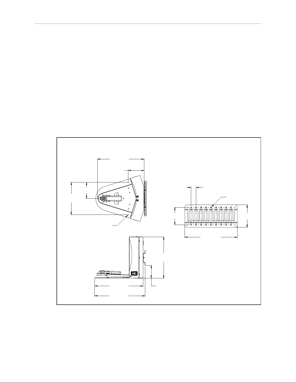
Requirements
89 [3.5]
114 [4.5]
267 [10.5]
247 [9.7]
123 [4.9]
121 [4.8]
356 [14.0]
315 [12.4]
369 [14.5]
384 [15.1]
Wall Mount
and Floor Mount
Units are mm [in.]
Wall Mount Bracket
98 ± 20
[3.8 ± 0.8]
3x Ø6 [0.25]
8x 25 [1.0]
18x Ø6 [0.25]
l
100 to 240 VAC, 50 to 60 Hz, 8 A
The station's power converter automatically detects the source voltage.
l
Ambient operating temperature: 5° to 40° C (41° to 104° F)
l
5 to 95% humidity, non-condensing
Wall Bracket Mount
1.
Attach the docking station mounting bracket to a wall, with the bottom edge of the
bracket 98 ± 20 mm (3.8 ± 0.8 in.) above the floor, using user-supplied anchors and
screws. There is leeway, so you can adjust the height a little bit.
Refer to the following figure:
Chapter 2: Setup
Figure 2-9. Docking Station, Wall Mount
Adept Lynx Platform User's Guide, Rev B
Page 30 of 116
Page 31

Chapter 2: Setup
2.
Screw the two shoulder bolts, each with a washer, into the rear of the docking station.
The shoulder bolts are M5 x 4, stainless steel. Their locations are shown in the following figure. Tighten to 9 N-m (80 in-lb).
Figure 2-10. Rear View of Docking Station with Wall Bracket
3.
Lower the docking station down, so the two bolts on the back of the docking station
slide into the bracket, to secure the docking station to the wall.
Floor-mount, without Floor Plate
Screw the base of the docking station directly to the floor, using three user-supplied screws. For
dimensions of the available holes in the base, refer to Figure 2-9. Adept recommends M5 selftapping or M4 sheet rock screwsfor this.
Floor-mount, with Floor Plate
This mounting method uses the floor plate. The floor plate is not shipped attached to the docking station, so you must attach it for this type of mount. It will be in the crate with the platform, right behind the docking station.
Adept Lynx Platform User's Guide, Rev B
Page 31 of 116
Page 32

Chapter 2: Setup
Attaching the Floor Plate
Refer to the following figures.
1.
Tip the docking station onto its back, so you can access the underside.
2.
Remove the two lowest screws (M4 x 12 flat-head), if present.
In the following figure, these screws are circled. The location of the third screw hole is
also circled.
3.
Attach the floor plate to the base of the docking station with three M4 x 12 flat-head
stainless steel screws.
The floor plate comes with three screws, so you will have two spares.
The docking station and floor plate do not need to be attached to the floor, as the weight of the
AIV on the floor plate will keep the docking station from moving.
Figure 2-11. Underside of Docking Station Foot, Showing Screw Locations
Adept Lynx Platform User's Guide, Rev B
Page 32 of 116
Page 33

Chapter 2: Setup
406 [16.0]
495 [19.5]
Free Standing
Units are mm [in.]
NOTE:These are the three locations for the M4 x 12 flat-head screws. Two are
already in place, and need to be removed before attaching the plate.
Figure 2-12. Docking Station, Mounted on Floor Plate
Figure 2-13. Docking Station Floor Plate Dimensions
Adept Lynx Platform User's Guide, Rev B
Page 33 of 116
Page 34

Chapter 2: Setup
All mounting methods
Install the power cord and turn the power switch to ON. The power switch is next to the
power plug. The blue power LED indicator should light.
Docking Station Contact Adjustment
The contacts on the docking station have five height settings. The station is shipped with the
height in the middle setting, which should be correct in most cases. The height can be changed
by tilting the station enough to see the bottom of the base, making the adjustment accessible.
NOTE:Squeeze and keep the platform foot against the bottom of the foot to make
this adjustment easier.
Adjust the height of the contacts by using the pull-knob on the bottom of the dock. The height
changes by 4 mm (0.15 in.) for each notch. See the following figure.
The height of the contacts should be set so that the roller is high enough to stay in contact with
the platform as it is docking, but low enough so that the bi-level of the roller guides the paddle
under the platform.
Figure 2-14. Docking Station Contact Adjusting Pull-Knob
Adept Lynx Platform User's Guide, Rev B
Page 34 of 116
Page 35

Chapter 3: Getting Started
The Adept Lynx platform comes with firmware and onboard software installed.
The configuration of parameters is performed with the MobilePlanner software, covered in the
Adept Motivity®User's Guide.
Other setup, mostly for communication, is handled by the SetNetGo OS, which is accessed
through the MobilePlanner software. It can also be accessed through a direct connection, so
your IT support can set up your wireless without needing the MobilePlanner dongle.
The Adept Lynx platform navigates using a map, generated with the MobilePlanner software.
The operation of this software, as well as the downloading of the resultant map to the platform, is covered in the Adept Motivity®User's Guide.
NOTE:The map must be generated and downloaded to the platform before you can
perform the steps covered in the Operation chapter of this manual.
The Adept Lynx platform is autonomous, but can be monitored and manually controlled
through the MobilePlanner or MobileEyes software. These are covered in the
Adept Motivity®User's Guide.
This chapter describes how to quickly start up, configure, and operate your new Adept Lynx
platform. For mapping and integration details, refer to the Adept Motivity®User's Guide.
3.1 Startup
Press and hold the power ON button for half a second, then release. It takes about a minute for
all the systems to start up and make their various interconnections. If the platform doesn't
start up, try power OFF, check your connections, and then power ON.
Startup is complete when the light discs stop indicating boot (two blue light segments, moving
in opposite directions from 6 o'clock to 12 o'clock and back).
Out-of-the-box, the platform does not have a working map, nor are its wired or wireless network settings likely to match your network. Consequently, it will not do anything autonomously, but you can drive it with the joystick or have it follow you around, in Follow Mode.
Adept recommends that you drive it to and position it onto its automated docking station in
preparation for the next steps. (Installation of the automated docking station was covered in
the previous chapter.)
Joystick
The joystick lets you quickly move the platform to its destination. This can be used to drive it
from the shipping dock to an automated docking station.
Adept Lynx Platform User's Guide, Rev B
Page 35 of 116
Page 36

Chapter 3: Getting Started
Trigger
Steering
Knob
Goal Button
Speed
Button
Trigger
The joystick plugs into the left side of the Lynx platform, under the small access panel at the
upper right corner of the platform. (The Maintenance Ethernet port is also there.) The access
panel is held in place with a push-push latch, and retained by a lanyard. See Figure 8-1.
WARNING: The Adept Lynx Platform Safety Scanning Laser is not tied
into the E-Stop chain when driven using the joystick. The platform will
still avoid obstacles detected by the Safety Scanning Laser. The sonar, on
the other hand, are disabled entirely when driving with the joystick.
Follow Mode
Connect the joystick, start up normally, then press the joystick GOAL button. Step in front of
the platform and it will now follow you wherever you go. Actually, it follows your legs or the
legs of anyone else who may step in front and capture its attention. This is useful if you need
to transport it to a different location.
Driving with the joystick, activation of an E-Stop, or any other mobility interaction, such as
through MobileEyes, stops Follow Mode.
3.2 Settings and Configuration
Preparing your Adept Lynx platform for autonomous mobile operation is very easy and takes
just a few moments. You attach a PC to the platform’s maintenance Ethernet port, and connect
Figure 3-1. Joystick
Adept Lynx Platform User's Guide, Rev B
Page 36 of 116
Page 37

Chapter 3: Getting Started
with the SetNetGo OS through the MobilePlanner SetNetGo interface. If you do not have wireless yet, you can connect MobileEyes and MobilePlanner through the wired Ethernet port
(Maintenance LAN) and set up the wireless network later.
Maintenance Ethernet Connection
Attach a pass-through or cross-over CAT5 (or better)Ethernet cable between the PC and the
Maintenance Ethernet port of the Adept Lynx platform. The Lynx Ethernet is Auto-MDIX, and
will detect the type of cable you are using. Set your computer’s IP address to 1.2.3.x, where x is
any number from 1 through 254, except 4. Manually set the net mask to 255.255.255.0. No special DNS or gateway settings are needed.
The Maintenance Ethernet plugs into the left side of the Lynx platform, under the small access
panel at the upper right corner of the platform. (The joystick port is also there.) The access
panel is held in place with a push-push latch, and retained by a lanyard. See Figure 8-1.
The platform's Maintenance Ethernet port is always enabled, and permanently set to IP
address 1.2.3.4, with a netmask of 255.255.255.0, for direct, wired access to the onboard systems.
Start the Network Connections:Local Area Connection dialog for the ETH 0 Ethernet port:
(Windows) Start > Settings > Network Connections > Local Area Connection
Select Properties, and, from its dialog, scroll to and double-click the Internet Protocol (TCP/IP)
option. In the Internet Protocol (TCP/IP) Properties dialog, click both ‘Use the following…’ associated radio buttons to enable them, and then type in the IP and netmask values.
SetNetGo Configuration
The SetNetGo OS is used to configure the Adept Lynx platform wireless Ethernet, among other
things. Refer to the Adept Motivity®User's Guide for details.
Mapping
In order to have your Adept Lynx platform perform autonomous mobile activities, you need to
make a map of its operating space. Use the MobilePlanner application to make maps. Refer to
the Adept Motivity®User's Guide.
The tasks involved are:
l
Make a floor plan scan while driving the platform with the joystick.
l
Load that floor plan scan into MobilePlanner, on your PC, to make and edit the map.
l
Transfer the working map back to the platform and share it with any other Lynx platforms in that workspace, to perform autonomous mobile actions.
l
Save map collections and deploy your platform in any of your working spaces by selecting the appropriate map file.
NOTE:It is a good idea to have the automated docking station installed prior to creating the map scan. Its distinctive diagonal face will be useful in locating and setting it up in the map.
Adept Lynx Platform User's Guide, Rev B
Page 37 of 116
Page 38

Page 39

Everything that you attach to the Lynx platform is referred to as the payload.
In some custom cases, Adept designs and builds the payload. In most cases, you will need to
design a payload that suits your application. This chapter discusses considerations to be
aware of when you design a payload for your Lynx platform.
The Lynx platform provides the mobility and navigation you will need, as well as power and
I/O connections between the platform and your payload, so the two can work effectively
together.
4.1 Considerations
The main factors to consider in designing a payload are the size, weight, and center of gravity
of the payload, and power requirements. Adding weight to the Lynx platform tends to have
less effect on run-time than adding electrical power requirements. Additional weight will have
more effect on carpet than on hard surfaces.
Weight
Increased payload weight will decrease your AIV's run-time. This will be most noticeable if
you are driving the AIV up an incline. On level ground, a certain amount of extra weight will
not shorten the AIV's run-time very much. When adding a payload with substantial weight,
the center of gravity of the entire AIV needs to be considered. This is particularly important if
you intend to equip the Lynx platform with a robot arm, which would be lifting items off-center from the Lynx platform.
Chapter 4: Payloads
A heavy payload, with most of its weight concentrated just above the Lynx platform, will be
much more stable than the same weight payload in which the weight is either off-center or
high above the top of the platform.
NOTE:The weight of your payload added to the weight of the parts it is carrying
must not exceed 60 kg (132 lb).
Power Consumption
Using devices on your payload that consume significant power will noticeably shorten the
run-time of the AIV. You should try to minimize such power consumption whenever possible.
Examples of power-consuming payloads would be one with a robot arm attached, or any
motorized fixture as part of the payload. The standard Operator screen and light discs consume some power, but are not significant compared to the rest of the platform.
The battery is rated at 1500 W*hr (1.5 kWh). Unloaded, the platform uses from 80 - 107 W.
With a full load, this increases to 94 - 125 W. (The range for each reflects the speed at which
the platform is driven.) You can use the wattage of any accessories you add to your payload,
added to these typical values, to calculate the expected run-time per charge.
Adept Lynx Platform User's Guide, Rev B
Page 39 of 116
Page 40

Chapter 4: Payloads
NOTE:In the following table, 50% is 900 mm/sec., 100% is 1800 mm/sec.
Table 4-1. Typical Watts Drawn
% Speed
kg 50 100
0 80 107
60 94 125
To calculate your estimated run-time:
1.
Find the closest match to your payload weight and average driving speed, as a percentage of full speed.
This will be a value in Watts.
2.
Add the power used by all electrical devices on your payload, in Watts.
It is unlikely that any electrical device on your payload will operate continuously, so
you need to figure out what average percent of the time it will operate, and multiply
that by the Watts of the drain to get an average drain factor.
3.
Divide 1500 W*hr by that value, in Watts.
This will yield your estimated run-time, in hours.
Example Calculation
If your payload weighs 60 kg, and you expect to run at an average of 50% full speed, you
would use the value of 94 from the table.
If your payload includes a device that draws 150 watts half of the time, add 75 (150*50%) to
94, to get 169 Watts, total.
Dividing 1500 W*hr by 169 Watts yields:
1500 W*hr/169 W = 8.87 hr of estimated run-time.
Payload Bay Access
The area between the Lynx platform and your payload is the payload bay. You will occasionally need to access the Lynx platform and the connectors in the payload bay. This is where
you can access all of the platform power and I/O connectors. It's a good idea to provide for
access to this when designing your payload.
If the payload is small and light enough, it can just be lifted off of the platform to access the
connectors in the payload bay. Care should always be taken not to damage any wiring
between your payload and the platform.
A larger, heavier payload may need some form of hinge, so that the payload can be tilted out
of the way while you access the payload bay. Consideration should be given to harness length
and position so that this can be accomplished without disconnecting or damaging any connectors or harnesses.
Adept Lynx Platform User's Guide, Rev B
Page 40 of 116
Page 41

Chapter 4: Payloads
145°
Units are mm [in.]
2x 50 [2.0]
2x 43 [1.7]
2x 146
[5.7]
4x 130
[5.1]
2x 49
[1.9]
2x 48
[1.9]
2x 43 [1.7]
2x 50 [2.0] 106 [4.2]
57 [2.2]
8x 50 [2.0]
8x 75 [3.0]
8x 73 [2.9]
4x 146 [5.7]
191
[7.5]
[7.3]
186
437 [17.2]
177 [7.0]
615
[24.2]
431
[17.0]
Dimensions
You must keep your payload no wider and no longer than the Lynx platform.
The most common payload is a vertical extension of the platform, adding whatever features
are needed by your application above the platform itself.
Take care to keep all of the payload higher than the top of the Lynx platform. If any of the platform's sensors get blocked, it won't be able to function normally. This is critical in the case of
the safety scanning laser.
If you purchased the optional vertical-mount lasers for your payload, you need to make sure
that the payload will not interfere with the view of those lasers. Typically, the vertical lasers
are mounted on the sides of the payload, so that they protrude enough to miss the payload
itself with the laser beam. Some customers have found it prudent to build a protective guard
over the vertical lasers, to protect the lasers from impact. Ensure that any such guard does not
block the laser beam.
The height of your payload will affect the center of gravity, covered in the next section.
Center of Gravity
Figure 4-1. Platform Deck Dimensions, for Attaching Payload
As much as possible, you should keep the payload center of gravity centered on the Lynx platform, and as low (close to the platform top) as possible. This will give you the best stability,
particularly when crossing thresholds or irregularities in the floor.
The following figure shows the center of gravity of the platform, without payload.
Adept Lynx Platform User's Guide, Rev B
Page 41 of 116
Page 42

Chapter 4: Payloads
499.6
697
Wheel
Axis
345.3
CG
16.5
249.8
372
CG
188.7
CG
16.5
Units are mm
Wheel
Axis
Rear of Lynx Platform
Front of Lynx Platform
Wheel
Axis
Figure 4-2. Center of Gravity of Platform
The three following figures show the calculations of safe placements for the center of gravity
for payloads with the weights listed. The center of gravity, in each instance, needs to be within
the area shown. All units are mm.
In the following three figures, light blue represents the payload, while dark (Adept) blue represents the Adept Lynx Platform.
NOTE:These figures show the limits of where the payload center of gravity can be
placed. You should try to keep your CG as close to the center of these figures as possible.
Adept Lynx Platform User's Guide, Rev B
Page 42 of 116
Page 43

10 kg
Chapter 4: Payloads
30 kg
Figure 4-3. Center of Gravity Graphs, 10 kg
Figure 4-4. Center of Gravity Graphs, 30 kg
Adept Lynx Platform User's Guide, Rev B
Page 43 of 116
Page 44

60 kg
Chapter 4: Payloads
Figure 4-5. Center of Gravity Graphs, 60 kg
4.2 Connections Between Platform and Payload
The Lynx platform provides a variety of I/O and power connections, which you can use to
make your AIV more effective.
The Operator screen, E-Stop, Brake-release, ON, and OFF can be "moved" using a single connector (the HMI Panel connector). This allows you to put many of the more common operator
controls somewhere on your payload with just one cable.
The cutout needed for mounting the Operator interface is shown in the following figure:
Adept Lynx Platform User's Guide, Rev B
Page 44 of 116
Page 45

Chapter 4: Payloads
0
7.06 (0.28)
23.02 (0.91)
42.07 (1.66)
61.12 (2.41)
77.06 (3.03)
84.14 (3.31)
89.51 (3.52)
5.39 (0.21)
0
1.52
(0.06)
11.97
(0.47)
6.35
(0.25)
78.98
(3.11)
151.61
(5.97)
159.48
(6.28)
169.93
(6.69)
161
(6.34)
70
(2.76)
4x Ø5
C
L
C
L
Punch Thru
3 mm (0.12)
Clearance Area
HMI Panel
Profile
(0.2) Thru
Units in mm (in.)
Figure 4-6. Operator Interface Cutout Dimensions
Many other options are available. Details and specifications of the connections available are
covered in Connectivity on page 47.
Adept Lynx Platform User's Guide, Rev B
Page 45 of 116
Page 46

Page 47

Most of the connections that are available to the user are in the payload bay, which is the
space between the platform and any payload placed on top of it. These include I/O and power
connections. Some are required; others are available if needed. The two exceptions are the Joystick port, and the Maintenance Ethernet port, which are located under a small access panel
on the left side of the Lynx platform, in the upper-right corner. Both of these connectors have a
second, equivalent connector inside the payload bay. See Figure 8-1.
5.1 Required Connections
l
Joystick port In order to generate maps with the Adept Lynx platform, you need to
connect a joystick to its Joystick port.
The Joystick port is located under a small access panel on the left side
of the platform, in the upper-right corner.
This is internally connected to the Joystick port in the payload bay.
l
Maintenance
Ethernet
The Maintenance Ethernet port is located under a small access panel
on the left side of the platform, in the upper-right corner.
Its IP address is 1.2.3.4, with Netmask 255.255.255.0.
Access to the SetNetGo OS is always enabled on this interface, and
does not require a password or a license.
Chapter 5: Connectivity
This is internally connected to the Maintenance Ethernet port in the
payload bay.
l
Wireless
Ethernet
For multi-AIV installations, or where you wish to send new commands or receive status updates from the AIV, you need to have wireless Ethernet.
l
Docking
The AIV needs access to a docking station so it can charge itself.
Station
5.2 Payload Bay Connections
These connections are available for use with Adept- and user-supplied accessories. The antennas and joystick come with the platform.
NOTE:Standard connectors, such as Ethernet and audio, are not covered here. This
includes all of the connectors on the right side of the core, shown in the following
figure:
Adept Lynx Platform User's Guide, Rev B
Page 47 of 116
Page 48

Digital
Ant1
Ant2
Audio In
Audio Out
Audio Out
Lynx Core Front, Upper
CAN Bus B Digital I/O
Analog I/O
User LANRS232-1RS232-2Aux Sensors
Chapter 5: Connectivity
Figure 5-1. Right Side of the Core
Figure 5-2. Front Upper Core
Connection Type Description
Ethernet RJ45,
Shielded
RS-232 (Aux Sensors) HDB15M Optional vertical lasers
RS-232 x 2 DB9M Port 1 and Port 2, general use
CAN Bus B DB9F Consult Adept for use.
Digital I/O (HDB44F) HDB44F 16 digital inputs, in 4 banks of 4. Each bank
General (USER LAN), Auto-MDIX.
can be wired as active high or active low
depending on the connection of the BANK# terminal.
VINrange for each input is 0 to 30 V. The input
is ON when VIN> 4 V, OFF when VIN< 1.3 V.
16 digital outputs, protected low-side (opendrain) drivers. 500 mA output each. May be
used with loads connected to VBAT, AUX_20V,
_12V, or _5V. You must stay within the
allowed current capacity of the VBAT or AUX
power supplies.
Analog I/O HDB15M General use
Adept Lynx Platform User's Guide, Rev B
Page 48 of 116
Page 49

CAN Bus B
Connector type DB9F
Use CAN Bus
Pin No. Designation Notes
1, 4, 8 No Connection
2 CANL_B CAN Communication differential pair
3, 6 GND Direct GND
5 SHIELDGND Bead filter to GND
7 CANH_B CAN Communication differential pair
9 CANB_12V_OUT_SW 12 V @ 0.5 A Max (switched in SW)
Digital I/O
Chapter 5: Connectivity
Connector type HDB44F
Pin No. Hardware Software Notes
1 INPUT_1.1 Input_1.1 0 – 30 V Range, Rin= ~3.9 kΩ
2 INPUT_1.2 Input_1.2 0 – 30 V Range, Rin= ~3.9 kΩ
3 INPUT_1.3 Input_1.3 0 – 30 V Range, Rin= ~3.9 kΩ
4 INPUT_1.4 Input_1.4 0 – 30 V Range, Rin= ~3.9 kΩ
5 BANK1 Common for INPUT_1.X
6 INPUT_2.1 Input_2.1 0 – 30 V Range, Rin= ~3.9 kΩ
7 INPUT_2.2 Input_2.2 0 – 30 V Range, Rin= ~3.9 kΩ
8 INPUT_2.3 Input_2.3 0 – 30 V Range, Rin= ~3.9 kΩ
9 INUIT2.4 Input_2.4 0 – 30 V Range, Rin= ~3.9 kΩ
10 BANK2 Common for INPUT_2.X
11 INPUT_3.1 Input_3.1 0 – 30 V Range, Rin= ~3.9 kΩ
Designation
12 INPUT_3.2 Input_3.2 0 – 30 V Range, Rin= ~3.9 kΩ
13 INPUT_3.3 Input_3.3 0 – 30 V Range, Rin= ~3.9 kΩ
14 INPUT_3.4 Input_3.4 0 – 30 V Range, Rin= ~3.9 kΩ
15 BANK3 Common for INPUT_3.X
Adept Lynx Platform User's Guide, Rev B
Page 49 of 116
Page 50

Chapter 5: Connectivity
Designation
Pin No. Hardware Software Notes
16 INPUT_4.1 Input_4.1 0 – 30 V Range, Rin= ~3.9 kΩ
17 INPUT_4.2 Input_4.2 0 – 30 V Range, Rin= ~3.9 kΩ
18 INPUT_4.3 Input_4.3 0 – 30 V Range, Rin= ~3.9 kΩ
19 INPUT_4.4 Input_4.4 0 – 30 V Range, Rin= ~3.9 kΩ
20 BANK4 Common for INPUT_4.X
21 OUTPUT_1 Output_1
22 OUTPUT_2 Output_2
23 OUTPUT_3 Output_3
24 OUTPUT_4 Output_4
25 OUTPUT_5 Output_5
26 OUTPUT_6 Output_6
27 OUTPUT_7 Output_7
28 OUTPUT_8 Output_8
29 OUTPUT_9 Output_9
30 OUTPUT_10 Output_10
31 OUTPUT_11 Output_11
32 OUTPUT_12 Output_12
33 OUTPUT_13 Output_13
34 OUTPUT_14 Output_14
35 OUTPUT_15 Output_15
36 OUTPUT_16 Output_16
37 VBAT_IO_OUT4 VBAT @ 0.5 A Max
(shared with light pole)
38 VBAT_IO_OUT3 VBAT @ 0.5 A Max
39 VBAT_IO_OUT2 VBAT @ 0.5 A Max
40 VBAT_IO_OUT1 VBAT @ 0.5 A Max
41, 42,
43, 44
GND
Adept Lynx Platform User's Guide, Rev B
Page 50 of 116
Page 51

Chapter 5: Connectivity
Table 5-1. Digital Input Specifications
Parameter Value
Operational voltage range 0 to 30 VDC
OFF state voltage range 0 to 1.3 VDC
ON state voltage range 4 to 30 VDC
Operational current range 0 to 7.5 mA
OFF state current range 0 to 0.5 mA
ON state current range 1.0 to 7.5 mA
Impedance (Vin/Iin) 3.9 kΩ minimum
Current at Vin= +24 VDC Iin≤ 6 mA
NOTE:The input current specifications are provided for reference. Voltage sources
are typically used to drive the inputs.
Figure 5-3. Typical Digital Input Wiring Example
Adept Lynx Platform User's Guide, Rev B
Page 51 of 116
Page 52

Chapter 5: Connectivity
Table 5-2. Digital Output Specifications
Parameter Value
Power supply voltage range 5 - 30 VDC
Operational current range, per channel I
ON state resistance (I
= 0.5 A) Ron≤ 0.14 Ω @ 85° C
out
Output leakage current I
≤ 500 mA
out
≤ 5 μA
out
DC short circuit current limit 0.7 A ≤ I
LIM
≤ 1.7 A
Analog I/O
Connector type HDB15M
Pin No. Designation Notes
1 ANALOG_IN1 0 – 10 V Range, Rin= ~35 kΩ
2 ANALOG_IN2 0 – 10 V Range, Rin= ~35 kΩ
3 ANALOG_IN3 0 – 10 V Range, Rin= ~35 kΩ
4 ANALOG_IN4 0 – 10 V Range, Rin= ~35 kΩ
5 ANALOG_IN5 0 – 30 V Range, Rin= ~110 kΩ
Figure 5-4. Typical Digital Output Wiring Example
Adept Lynx Platform User's Guide, Rev B
Page 52 of 116
Page 53

Pin No. Designation Notes
6 ANALOG_IN6 0 – 30 V Range, Rin= ~110 kΩ
7 ANALOG_IN7 0 – 30 V Range, Rin= ~110 kΩ
8 ANALOG_IN8 0 – 30 V Range, Rin= ~110 kΩ
9 ANALOG_OUT1 0 – 20 V Range, ±10 mA, Ro = ~200 Ω
10 ANALOG_OUT2 0 – 20 V Range, ±10 mA, Ro = ~200 Ω
11 ANALOG_OUT3 0 – 20 V Range, ±10 mA, Ro = ~200 Ω
12 ANALOG_OUT4 0 – 20 V Range, ±10 mA, Ro = ~200 Ω
13, 14, 15 GND
Aux Sensors
Connector type HDB15M
Use Optional vertical lasers
Chapter 5: Connectivity
Designation
Pin No. Hardware Software Notes
1 RS232_VERT1_TXD
2 RS232_VERT2_TXD
3 RS232_FOOT_TXD
4 5V_SW1 USB_1_and_2_Power 5 V @ 1 A (shared with USB port 1)
5, 10 SW_20V_VERT Vertical_Laser_Power 20 V @ 300 mA
6, 7, 8 GND
9 5V_SW2 USB_1_and_2_Power 5 V @ 1 A (shared with USB port 2)
11 RS232_VERT1_RXD
12 RS232_VERT2_RXD
13 RS232_FOOT_RXD
14 5V_SW3 USB_3_Power 5 V @ 1 A (shared with USB port 3)
15 SW_20V_FOOT Foot_Laser_Power 20 V @ 150 mA
RS232 1 & 2
Connector type DB9M
Use Port 1 and 2, General Use
Adept Lynx Platform User's Guide, Rev B
Page 53 of 116
Page 54

Lynx Core Rear, Upper
Light Pole User Interface User Bumpers Aux Power User Power
Maint LAN Joystick HMI Panel Sonar 2
Chapter 5: Connectivity
Pin No. Designation Notes
1, 4, 6, 9 No Connection
2 RS232_USR#_RXD #=1 or 2
3 RS232_USR#_TXD #=1 or 2
5 GND
7 RS232_USR#_RTS #=1 or 2
8 RS232_USR#_CTS #=1 or 2
Figure 5-5. Rear Upper Core
Connection Type Description
Light Pole Mini-Fit2 x 3 Connects to a user-supplied light tower with 3 lights and 1
buzzer, using a default configuration
NOTE:The following four functions are pins on the User Interface connector.
Brakerelease
ON Pins for user-supplied ON button; same function as Operator
OFF Pins for user-supplied OFF button; same function as Operator
ESTOP Pins for user-supplied E-Stop
User Bumpers
Mini-Fit 2 x 7 Pins for user-supplied brake release
Panel ON
Panel OFF
Mini-Fit 2 x 4 Payload bumpers, user-supplied, connected between ESTOP_
SRC and USER_BMP# (for each of the 6 inputs).
Contacts should be 12 V @ 10 mA.
Adept Lynx Platform User's Guide, Rev B
Page 54 of 116
Page 55

Chapter 5: Connectivity
Connection Type Description
Aux Power Mini-Fit 2 x 3 5, 12, and 20 VDC Outputs
User Power Mini-Fit 2 x 6 Battery and switched battery power
Maintenance
Ethernet
Joystick DB9F Directly connected to the externally-mounted Joystick port
HMI Panel HDB15F Operator screen, E-Stop, Brake_Rel, ON, OFF
Sonar #2 DB9M Optional sonar (x8) for payload
Power Connections
RJ45,
Shielded
Directly connected to the externally-mounted Maintenance Ethernet, Auto-MDIX.
The Lynx platform provides conditioned 5, 12, and 20 VDC, and raw (battery) 22 - 30 VDC
power to the platform’s and accessory electronics, including the onboard Lynx core and safety
scanning laser LIDAR (Light Detection And Ranging).
All power connectors are Mini-Fit®.
Nominal Qty Actual
5 VDC 1 5 VDC 1 A Switched Aux power
12 VDC 1 12 VDC 1 A Switched Aux power
20 VDC 1 20 VDC 1 A Switched Aux power
22 - 30 VDC 2 battery 4 A Switched
Maximum
Current
Description
22 - 30 VDC 1* battery 10 A Switched
22 - 30 VDC 1* battery 10 A Safe, Switched
* 10 A Switched and 10 ASafe, Switched share the 10 A of current.
Each supply has an associated LED which, when lit, indicates that the port is actively
powered. See Lynx Core Indicators on page 77.
The Safe 22 - 30 VDC supply automatically gets disconnected when the E-Stop button is
pressed, an obstacle is detected, or the bumper touches something.
Light Pole (user-supplied)
Connector type Mini-Fit®3 x 2
Use Light tower
Pin No. Designation Notes
1 GND
2 LIGHT_P1
Adept Lynx Platform User's Guide, Rev B
Page 55 of 116
Page 56

Chapter 5: Connectivity
Pin No. Designation Notes
3 LIGHT_P2
4 VBAT_IO_OUT4 VBAT @ 0.5A Max (shared with DIO)
5 LIGHT_P3
6 LIGHT_P4
NOTE:Light 4 is the buzzer on the light tower.
User Interface
Connector type Mini-Fit®7 x 2
Use Brake release, ON, OFF, E-Stop
Pin No. Designation Notes
1, 2, 3 FBAT_ALWAYS Fused VBAT @ 500 mA
4 ESTOP_USR_1L Short 4 & 11 to close ESTOP_USR_1
5 ESTOP_USR_2L Short 5 & 12 to close ESTOP_USR_2
6 ESTOP_OUT_1L Pins 6 & 13 short when ESTOP_CH1 is closed
7 ESTOP_OUT_2L Pins 7 & 14 short when ESTOP_CH2 is closed
8 OFF_BUTTON Short to FBAT_ALWAYS to signal OFF (min 1 s pulse)
9 START_BUTTON Short to FBAT_ALWAYS to signal ON (min 1 s pulse)
10 MOTOR_BRAKE Short to FBAT_ALWAYS for manual brake release
11 ESTOP_USR_1H Short 4 & 11 to close ESTOP_USR_1
12 ESTOP_USR_2H Short 5 & 12 to close ESTOP_USR_2
13 ESTOP_OUT_1H Pins 6 & 13 short when ESTOP_CH1 is closed
14 ESTOP_OUT_2H Pins 7 & 14 short when ESTOP_CH2 is closed
NOTE:An E-Stop jumper or a user-supplied E-Stop button needs to be attached to
the E-STOP port on the User Interfaceconnector for the platform to function. The
jumper is provided as part number 12730-000L. An E-Stop button would be usersupplied.
Adept Lynx Platform User's Guide, Rev B
Page 56 of 116
Page 57

Chapter 5: Connectivity
Figure 5-6. E-Stop Chain Diagram
Adept Lynx Platform User's Guide, Rev B
Page 57 of 116
Page 58

Chapter 5: Connectivity
User Bumper
Connector type Mini-Fit®4 x 2
Use Optional bumper (x8) for payload
Pin No. Designation Notes
1 USER_BUMPER_1 Short to ESTOP_SRC to signal bumper hit
2 USER_BUMPER_2 Short to ESTOP_SRC to signal bumper hit
3 USER_BUMPER_3 Short to ESTOP_SRC to signal bumper hit
4 USER_BUMPER_4 Short to ESTOP_SRC to signal bumper hit
5 USER_BUMPER_5 Short to ESTOP_SRC to signal bumper hit
6 USER_BUMPER_6 Short to ESTOP_SRC to signal bumper hit
7, 8 ESTOP_SRC 12 V ESTOP Source Output @ 10 mA
Aux Power
Connector type Mini-Fit®3 x 2
Pin No. Hardware Software Notes
1, 2, 3 GND
4 AUX_5V_OUT Aux_5V 5 V @ 1 A max
5 AUX_12V_OUT Aux_12V 12 V @ 1 A max
6 AUX_20V_OUT Aux_20V 20 V @ 1 A max
Designation
Adept Lynx Platform User's Guide, Rev B
Page 58 of 116
Page 59

Chapter 5: Connectivity
User Power
Connector type Mini-Fit®6 x 2
Designation
Pin No. Hardware Software Notes
1, 2,
3, 4,
5, 6
7 SW_VBAT_OUT1 Battery_Out_1 VBAT @ 4 A max (switched in SW)
8 SW_VBAT_OUT2 Battery_Out_2 VBAT @ 4 A max (switched in SW)
9, 10* SW_VBAT_OUT34 Battery_Out_3_and_4 VBAT @ 10 A max (switched in SW).
11, 12* SAFE_VBAT_OUT SW_VBAT_OUT34 gated by
*9,10 and 11,12 share the 10 A of current.
Joystick
Connector type DB9F
Use Joystick
GND Limit to < 5 A per pin
Limit to < 5 A per pin.
dual-channel ESTOP relays.
Pin No. Designation Notes
1 JOY_XAXIS Analog X input
2 JOY_YAXIS Analog Y input
3 JOY_SPEED Analog SPEED input
4 JOY_GOAL Goal Button Input
5 JOY_EN_1H Enable channel 1
6 JOY_EN_2L Enable channel 2
7 No Connection
8 GND
9 5V 5 V @ 100 mA
Adept Lynx Platform User's Guide, Rev B
Page 59 of 116
Page 60

Chapter 5: Connectivity
HMI Panel
Connector type HDB15F
Use Operator screen, E-Stop, Brake_Rel, ON, OFF
Designation
Pin No. Hardware Software Notes
1 RS422_HMI_TX+
2 RS422_HMI_TX-
3 MOTOR_BRAKE
4, 5 ESTOP_FP_1H, _2H
6 RS422_HMI_RX+
7 RS422_HMI_RX-
8 START_BUTTON
Connections to Adept HMI Panel
9, 10 ESTOP_FP_1L, _2L
11 HMI_5V_SW HMI_Power
12, 14 GND
13 OFF_BUTTON
15 FBAT_ALWAYS
Sonar 1 & 2
Connector type DB9M
Use Platform sonar & optional sonar (x8) for payload
NOTE:Sonar 1 is part of the Internal Lynx Core connections.
Designation
Pin No. Hardware Software Notes
1, 4, 8 No Connection
2 RS422_SNR_RX+
3 RS422_SNR_TX+
5 GND
6 RS422_SNR_RX-
Connections to Adept Sonar Module
# = 1 or 2
7 RS422_SNR_TX-
9 SW_12V_SNR Sonar_#_Power
Adept Lynx Platform User's Guide, Rev B
Page 60 of 116
Page 61

Chapter 5: Connectivity
VGA Wheel Lights Sonar 1
Charge
Contacts
Battery
Power
Debug
USB1
USB2USB3
Bumper Speakers Batt Comm.
LIDAR R. Motor L. Motor
5.3 Internal Lynx Core Connections
The following connections are internal (under the platform's top deck), and not normally available for the user. They are listed here so that you can reconnect them in the event that they
need to be disconnected for parts replacement.
Connection Type Description
VGA HDB15F Reserved
Wheel Lights DB9F Motion and status indicator
Sonar #1,
RS-422
Charge Contacts Mini-Fit Sr., 2-pin
Debug RS-232 DB9M Reserved
USB x 3 USB Type A Reserved
LIDAR HDB26M Safety Scanning Laser
Figure 5-7. Internal Connectors on the Lynx Core (Front)
light discs on the platform sides
DB9M Connection to Adept Sonar Module
(Front bumper and rear sonar sensors)
Adept Lynx Platform User's Guide, Rev B
Page 61 of 116
Page 62

Chapter 5: Connectivity
Connection Type Description
Right Motor HDB26F NOTE:The Right and Left Motor connectors use
Left Motor HDB26F
Battery Power Mini-Fit Sr., 3-pin Battery VDC; connects to battery
Bumper Switches Mini-Fit 2 x 4 Connect to standard bumper contacts
Speakers Mini-Fit 2 x 2 Drives built-in speakers
Battery Comm. Mini-Fit 2 x 3 Battery communication/control
the same type of plug. Take care not to reverse them.
Lynx Internal Data Pinouts
Wheel Lights (Light Discs)
Connector type DB9F
Use Motion and status indicator light discs on the platform sides
Designation
Pin No. Hardware Software Notes
1, 2 CANL_A CAN Communication differential pair
3, 4 GND Direct GND
5 SHIELD GND Bead filter to GND
6, 7 CANH_A CAN Communication differential pair
8, 9 SW_12V_WHEEL WheelLight_Power 12 V @ 1 A Max (switched in SW)
NOTE:Sonar 1 is covered at the end of Core, Upper Rear.
Adept Lynx Platform User's Guide, Rev B
Page 62 of 116
Page 63

Chapter 5: Connectivity
LIDAR (Light Detection And Ranging)
Connector type DB26M
Use Front safety scanning laser
Designation
Pin No. Hardware Software Notes
1 RS422_LIDAR_RX+
2 RS422_LIDAR_RX-
3 OSSD1
4 OSSD2
5 WF_OUT
6 O3_OUT
7 STANDBY
8 EDM
9 No Connection
10, 18 SW_20V_LIDAR Main_Laser_Power
11 thru 17 GND
19 RS422_LIDAR_TX+
20 RS422_LIDAR_TX-
21 IN_A1
22 IN_A2
23 IN_B1
24 IN_B2
25 IN_C1
26 IN_C2
Pin 10 +18:Current < 600 mA
Connections to Adept-Supplied LIDAR
Adept Lynx Platform User's Guide, Rev B
Page 63 of 116
Page 64

Chapter 5: Connectivity
Lynx Internal Power Pinouts
Bumper
Connection Mini-Fit®4 x 2
Connector type DB9F
Use Front bumpers
Pin No. Designation Notes
1 BUMPER_R2L Right, Channel 2, Low
2 BUMPER_R1L Right, Channel 1, Low
3 BUMPER_L2L Left, Channel 2, Low
4 BUMPER_L1L Left, Channel 1, Low
5 BUMPER_R2H Right, Channel 2, High
Speakers
Connector type Mini-Fit®2 x 2
Use Speakers
6 BUMPER_R1H Right, Channel 1, High
7 BUMPER_L2H Left, Channel 2, High
8 BUMPER_L1H Left, Channel 1, High
Pin No. Designation Notes
1 RIGHT+
Right Speaker
2 RIGHT-
3 LEFT+
Left Speaker
4 LEFT-
Adept Lynx Platform User's Guide, Rev B
Page 64 of 116
Page 65

Batt Comm.
Connector type Mini-Fit®3 x 2
Use Battery control
Pin No. Designation Notes
1 GND
2 RS232_BATT_RXD
Chapter 5: Connectivity
3 RS232_BATT_TXD
4 FBAT_ALWAYS
5 START_BUTTON
6 OFF_BUTTON
Connections to the Adept-Supplied Battery
Adept Lynx Platform User's Guide, Rev B
Page 65 of 116
Page 66

Page 67

Before proceeding, you need to have performed the steps covered in the Setup and Getting Started chapters, so your platform has a map to work from.
6.1 Operating Environment
The Adept Lynx platform is designed to operate in an environment that is wheelchair accessible. Care must be taken to avoid:
l glass doors and walls
l pits without railings or low bumpers
l floors with access panels removed
l loose cables, hoses, etc.
l large, highly-reflective objects
Floors must provide good traction, typical of good walking conditions.
Chapter 6: Operation
l Slope
l Step traversal
l Gap traversal
l Temperature
l Humidity
The Adept Lynx platform is not intended for use in hazardous environments (explosive gas,
water, dust, oil mist). It has an IP rating of IP-44.
6.2 Typical Operation
During normal startup, your Adept Lynx platform powers all its onboard systems1and runs
its onboard software and your integrated processes automatically to provide an applicationready AIV. If it has been given a map of its workspace and knows where it is within that environment (localized), your AIV is ready to perform on startup and will operate autonomously,
without human intervention.
The following applications are covered in detail in the Adept Motivity®User's Guide.
There are many options for configuring and tuning your Adept Lynx platform to best suit your
application.
Maps are developed with the MobilePlanner application. These may contain a variety of virtual elements, including special lines and sectors which act to modify the behavior of an
up to 1:12
up to 15 mm (0.6 in.)
up to 15 mm (0.6 in.)
5° to 40° C (41° to 104° F)
5 to 95%, non-condensing
1
As configured either by the factory or through your own parameter changes.
Adept Lynx Platform User's Guide, Rev B
Page 67 of 116
Page 68

Adept Lynx platform. Virtual elements include forbidden lines and areas, speed zones, preferred-direction zones, and more, all working to help you configure your platform’s workspace
for efficient and safe performance of your mobile application. You can also create your own virtual elements for application-specific AIV-workspace interactions.
Maps contain a variety of goals, routes, and tasks that comprise the destinations and activities
of the AIV in the workspace.
Paths are not pre-programmed, but instead are generated dynamically onboard the platform.
Paths are updated many times per second to maintain a smooth trajectory and to account for
any obstacles that are detected by the onboard sensors. Navigational parameters are stored
onboard the platform, and can be viewed and modified using the MobilePlanner software. The
MobilePlanner software is covered in the Adept Motivity®User's Guide.
The MobilePlanner application, running on your computer, is used to configure the many
high-level operating characteristics of the platform, including speeds and accelerations, sensor
safety zones, minimum battery level allowed before docking for recharging, which map to use,
and many other parameters. The MobilePlanner software typically communicates with the platform over the wireless network. A direct connection, through the maintenance Ethernet port on
the platform, is also possible.
6.3 Power and Charging
Chapter 6: Operation
The Adept battery is sealed. It supplies ample power for the motors, electronics, and accessories.
The platform ships separately from the battery. The battery is shipped fully-charged. You
should have installed the battery in the platform in Setup on page 19.
Battery recharging is managed by the platform. With ample power, as is provided by the automated docking station, all onboard systems function continuously while the battery recharges.
The Operator screen shows % state-of-charge (SOC)remaining for battery.
Run-time, with no load, is approximately 13 hours. This will vary significantly depending on
use and accessory power consumption.
Recharge time is approximately 3.5 hours.
Battery Indicators and Controls
The battery has one push-button and four LEDs. From left to right, they indicate:
LED Color Meaning
1 Red Error condition
Green 25% state of charge
2 Green 50% state of charge
3 Green 75% state of charge
4 Green 100% state of charge
Adept Lynx Platform User's Guide, Rev B
Page 68 of 116
Page 69

Chapter 6: Operation
Figure 6-1. Battery LEDs, Push-Button, Power Cable, and Data Cable
The push-button "wakes up" the battery, so it displays its state of charge. This can be useful
when a battery is in storage, and you need to know its state of charge.
Automated Docking Station
The automated docking station is both a manual and an automated means for recharging your
battery.
During normal, autonomous operation of the Adept Lynx AIV in the workspace, the AIV manages charging automatically through the automated docking station. The AIV will approach
the docking station frontward, and then turn around and back onto the docking station to
charge. There is up to a 10-second delay between when a AIV docks and when the charging
LED turns on.
Powering ON or OFF the AIV, or connecting and disconnecting the AIV with network and
onboard clients will not disturb the charging state. (Moving the AIV will, of course.) The station supplies ample power for all onboard systems while charging its battery, so you can continue operating those systems while charging.
If the AIV is powered off, it will turn on automatically when it is pushed onto the docking station. An AIV cannot be turned off while on the docking station.
Adept Lynx Platform User's Guide, Rev B
Page 69 of 116
Page 70

Chapter 6: Operation
Figure 6-2. Docking Station
Indicators, Controls, and Connections
The docking station has a power switch and two LEDs:
l
blue indicates that power is available.
l
yellow indicates that a charge is in progress.
The power plug for AC supply is on the right side of the station, as viewed from the front.
Power requirements are 100 - 240 VAC, 50 - 60 Hz, and 8 A.
The plug for connecting the manual charging cable is on the left side of the station, as viewed
from the front.
Adept Lynx Platform User's Guide, Rev B
Page 70 of 116
Page 71

Chapter 6: Operation
Environmental Requirements
l
Ambient temperature range:5° to 40° C (41° to 104° F)
l
Humidity:5 to 95% non-condensing
Maintenance
The docking station contacts should be cleaned quarterly with isopropyl alcohol. See Docking
Station Contacts on page 85.
The guide roller can be replaced in the field. See Docking Station Roller and Bearing on page
94.
If necessary, the height of the docking station contacts can be adjusted. See Docking Station
Contact Adjustment on page 34.
Manually Charging the Battery
Inside the Platform
To manually charge a battery inside the platform, push the AIV backwards, with E-STOP
engaged, so that the rear of the platform slides over the contacts of the docking station.
NOTE:You will need to press the brake release button first.
Outside the Platform
The battery can be charged, outside of the platform, by using the connector on the left side of
the docking station (viewed from the front)with the provided charging cable. This will most
likely to be used for charging a spare battery, while the second battery is still in the platform,
and the platform is in use.
There is up to a 10-second delay between when you connect the battery cable and when the
charging LED turns on.
NOTE:The docking station cannot charge a platform and a separate battery at the
same time. If a platform is at the station, the power to the manual charge connector
is cut off.
6.4 Operator Panel
The Operator panel comprises a screen, an E-Stop button, ON and OFF buttons, a brake-release
button, and a keyswitch. The panel will typically be mounted on the payload, so that it is easily reached by an Operator.
Screen
The screen is a color TFT, 320 x 240 pixels, 3.5 in. diagonal. It can display 256K colors, and is
backlit.
NOTE:Tapping lightly on the screen will turn on the backlight, in case it has timed
out.
Adept Lynx Platform User's Guide, Rev B
Page 71 of 116
Page 72

Chapter 6: Operation
Default/Sample Screen Contents
The first screen, during boot-up, will be the following:
Figure 6-3. Initial Boot Screen
Once the Lynx platform is booted, you will see the main screen:
Figure 6-4. Fields of the Main Screen
Adept Lynx Platform User's Guide, Rev B
Page 72 of 116
Page 73

Chapter 6: Operation
l
Up to six messages will be displayed in the main screen, in order of importance.
l
Only one fault at a time will be displayed.
l
Any event or condition that causes an ARAM restart or AIV shut down will be displayed, giving the cause of the restart or shut down.
E-Stop
When pressed, the red, latching push-button removes power from the platform’s motors and
from the E-Stop power port after a 1 second delay, giving the software time to stop the platform gently. To reset the E-Stop, twist the button slightly, so it pops up.
The motors must also be explicitly enabled, either with the dialog box that will pop up or with
the ON button. (This is not the case if the AIV is docked or experienced a critical driving fault.)
This can be done either with the MobilePlanner (with Map >Show Robot on) or MobileEyes
software, or with an ARCL command. See the following figure:
Figure 6-5. Motor Enable Pop-up Dialog
There is, in fact, a second pop-up that will say the E-Stop has been cleared, and you need to
click Enable to re-enable the motors.
ON Button
The ON button is used for restoring power after the OFF button has been pressed, and the software has finished shutting down the AIV.
It can also be used to restore power after an E-Stop has been pressed.
OFF Button
The red OFF button removes power from all systems except the charging hardware circuits.
The platform's software systems prevent loss of data on shutdown, and save the platform’s
last known location so it automatically localizes when it is next powered on.
NOTE:The OFF button can be disabled by the keyswitch, which can be locked.
Adept Lynx Platform User's Guide, Rev B
Page 73 of 116
Page 74

Chapter 6: Operation
Brake-release Button
The brake-release is used when you need to manually move the platform.
Keyswitch
The keyswitch can be used to disable the OFF button. The key can be removed in either the
locked or unlocked positions.
6.5 Other Controls and Indicators
Light Discs, Light Tower
Circular lights on the sides of the platform are used to indicate motion, turns, and several
other states. A user-supplied light tower can be added for extra signaling.
Their states are described here, and summarized in the following tables.
Stopped, no errors (ready)
Entire light disc on each side pulses blue slowly (0.25 Hz). Light tower is steady green.
Driving Straight
Blue arcs on each side of the platform will appear to rotate in the direction of the platform's
travel, to let nearby people know that it is moving (or about to move). Light tower is green and
buzzer sounds, both intermittently.
Turn Signals (for turns >30 degrees)
The blue drive indicators will include a blinking orange segment at the front of one light disc
to indicate that the platform is about to turn in the direction of the signal.
Light tower is green blinking and intermittent buzzer (same as driving straight).
Obstacle Detected
The light discs will blink yellow if the Lynx AIV is stopped for an object in its safety zone.
Light tower is yellow blinking.
Warning, Driving or Stopped (doesn't prevent driving, such as low battery)
The light discs will be orange instead of blue for Stopped, Driving, and Turn Signals.
Light tower alternates green with buzzer then yellow if driving, Long green alternates with
short yellow if stopped.
Lost
When the platform is lost, the light discs will each display two orange arcs, traveling from the
6 o'clock to the 12 o'clock position and back, in opposite directions. Light tower blinks yellow.
Charging
When docked, a green arc will indicate the current state of charge (SOC), showing steady green
from the top of the disc to the current SOC. A small white arc travels back and forth between
the two ends of the green arc. Light tower is off.
Adept Lynx Platform User's Guide, Rev B
Page 74 of 116
Page 75

Chapter 6: Operation
Lynx Left Side Lynx Right Side State of Charge
0 to 90 cw 0 to 270 ccw 25%
0 to 180 cw 0 to 180 ccw 50%
0 to 270 cw 0 to 90 ccw 75%
full circle full circle 100%
E-Stop
The light discs will blink red in an E-Stop condition. Light tower blinks red.
Booting
When booting, the light discs will display two blue arcs, traveling from the 6 o'clock to the 12
o'clock position and back, in opposite directions. Light tower alternates green, yellow, then red.
In the following table:
l
Blink indicates that a disc/light/buzzer is on for a period, then off for a period.
l
Pulse indicates a 0.25 Hz fade on and off.
l
Circle indicates that the lights appear to be going in a circle.
l
Half-circles indicates two arcs, moving opposite each other between the top and bottom.
l
Solid indicates that a light is on, with no off interrupting it.
l
Alt indicates that the light tower switches between different lights (and/or buzzer), with
no pause. Two lights with Alt means one light is always on, but not two at once.
Table 6-1. Indicator Meanings
Light Disc Light Tower Meaning
Color Pattern Color Pattern
1 Blue Pulse Green Solid Stopped, all ok
2 Blue Moving
Circle
3 Blue/
Orange
@front
Moving
Circle/
Blinking signal
4 Yellow Blink Yellow Blink Object detected in
Green+Buzzer Blink Driving Straight,
all ok
Green+Buzzer Blink Turning > 30 degrees in
direction of orange turn
signal, all ok
safety zone
5 Orange Same as
1,2,3
(Green+Buzzer)
/Yellow if driving
Green/Green/Green
/Yellow if stopped
Alt
Alt
Warning, doesn't prevent driving - applies to
driving, turning, and
stopped
e.g. low battery
6 Orange Left+Right Yellow Blink Lost
Adept Lynx Platform User's Guide, Rev B
Page 75 of 116
Page 76

Chapter 6: Operation
Trigger
Steering
Knob
Goal Button
Speed
Button
Trigger
Light Disc Light Tower Meaning
Color Pattern Color Pattern
Half-circles
7 Red Blink Red Blink E-Stop, stops driving
8 Green/White
arc
9 Blue Left+Right
quarter, half, or
three-quarter
green arc
Half-circles
no signal n/a Charging
Green/Yellow/Red Alt Booting
Joystick
The joystick plugs into the left side of the Lynx platform, under the small access panel at the
upper-right corner of the platform. See Location of Parts on the Platform on page 83. A second,
identical joystick port is located on the rear side of the Lynx core.
Figure 6-6. Joystick Buttons and Trigger
Use the joystick to drive the Lynx platform manually. Squeeze the trigger to drive.
Push the handle forward or back to make the platform move in that direction. Push the handle
to the side to make the platform rotate in that direction. Diagonal positions of the handle drive
the platform in an arc.
Adept Lynx Platform User's Guide, Rev B
Page 76 of 116
Page 77

Chapter 6: Operation
The Adept Lynx platform slows to a stop when you release the trigger. To stop more quickly,
continue to squeeze the trigger and pull or push the joystick handle to its limit in the opposite
direction of the platform’s travel.
The joystick’s GOAL button is for marking positions while making a map scan. When not making maps, press GOAL to enter Follow Mode. See Follow Mode on page 36.
WARNING: The Adept Lynx Platform Safety Scanning Laser is not tied
into the E-Stop chain when driven using the joystick. The platform will
still avoid obstacles detected by the Safety Scanning Laser. The sonar, on
the other hand, are disabled entirely when driving with the joystick.
Maintenance Ethernet
The Maintenance Ethernet port is on the left side of the Lynx platform, under the small access
panel at the upper-right corner of the platform. This is internally connected to the Ethernet port
located on the rear side of the Lynx core in the payload bay.
The Maintenance Ethernet port is permanently set to IP address 1.2.3.4, with a netmask of
255.255.255.0, for direct, wired access to the onboard systems. Accordingly, when accessing the
port, manually set the offboard computer’s Ethernet to an IP 1.2.3.x, where x is any number 1
through 254 except 4, and with a netmask of 255.255.255.0. No special DNS or gateway settings are needed.
Lynx Core Indicators
The left end of the Lynx core has 12 indicator lights. The following table gives their meanings:
Indicator Meaning
Left Column
LOGIC The microcontroller has power
PC The Lynx core and the servo controller are communicating
DRIVE The drive wheels are under servo control
ESTOP An E-Stop has been activated
Middle Column
20V 20 V power is available
12V 12 V power is available
5V 5 V power is available
VBAT Raw battery power is available
Right Column
LANUSER The USER LAN connector is showing activity
LANMAINT The Maintenance Ethernet connector is showing activity
WLAN The WiFi is showing activity
HD The hard drive is showing activity
Adept Lynx Platform User's Guide, Rev B
Page 77 of 116
Page 78

6.6 Sensors
Safety Scanning Laser
The onboard safety scanning laser is a very precise scanning sensor. The laser provides 500
readings in a 250 degree field of view, with a typical maximum range of 15 m (49.2 ft). The
laser operates in a single plane, positioned at about 191 mm (7.5 in.) above the floor. In most
environments, the sensor will provide highly-accurate data.
Glass, mirrors, and other highly-reflective objects cannot be reliably detected by the laser. Caution must be exercised when operating the platform in areas that have these types of objects. If
the platform will need to drive in close proximity of these objects, Adept recommends that you
use a combination of markings on the objects, such as tape or painted strips, and also use forbidden sectors in the map, so that the platform knows to plan paths safely around these
objects.
Sonar
Rear-Facing
The Adept Lynx platform’s four rear-facing sonar are for obstacle-sensing while backing up.
The range is up to 5 m (16 ft), though the typical accurate range is only up to 2 m (10 ft). Note
that the only two times the platform will back up is when docking on the docking station, or
when the bumper has hit an obstacle. In the latter case, the platform will back up just enough
so that it can rotate without touching the obstacle.
Chapter 6: Operation
Front-Facing
The platform's front bumper houses four sonar units, for detecting low obstacles.
Other Sensors
Encoders and Gyroscope
Each wheel has an encoder that tells the navigation system how far the wheel has turned, and
in which direction. Each wheel also has a Hall sensor.
The Lynx core has a gyroscope mounted on it, to track the platform's rotation.
The combination of rotation and distance traveled are used by the platform to back up the
safety scanning laser during localization. These limit the area on the platform's map that the
platform needs to search.
Bumper
One bumper, with two pairs of sensors, is mounted at the front of the platform, should the
obstacle-avoidance systems fail to detect an obstacle.
Optional user (payload) bumpers can be added using the User Bumper connector on the rear
upper core, in the payload bay.
Vertical Lasers Option
Two vertically-mounted lasers are available as an option. These are typically mounted on the
sides of the payload, to detect objects that protrude into the AIV's path, but but at a height that
is not detected by the safety scanning laser, such as shelves that stick out.
Adept Lynx Platform User's Guide, Rev B
Page 78 of 116
Page 79

Acuity Localization Option
Adept’s Acuity Localization uses an upward-facing camera to localize the platform using overhead lights. This can be used in circumstances where laser localization is difficult, either
because the environment has too many changing features or simply not enough features for
localization. If there are many objects, such as pallets or carts, which change location frequently, they will not show up on a map, and may also block the laser’s view of features that
are on the map. In such cases, Acuity Localization may be a better choice than using the safety
scanning laser for localization.
6.7 Startup
By default, the Lynx core, safety scanning laser, and some auxiliary power start automatically
when you press ON. To change that behavior, or to assign AUX power to your own accessories, modify their related parameters from the MobilePlanner software. You can also control
power from a client connected with the Lynx core.
Networking
The Lynx core is preset and tested on a Class-C network (netmask for all ports 255.255.255.0).
The Maintenance Ethernet port is set to IP address 1.2.3.4 and the wireless IP comes set with
an AP-based (“managed”) SSID of “Wireless Network”, unsecured. Consult with your network
systems administrator before modifying these network details through the SetNetGo OS.
Chapter 6: Operation
The USER LANport is set to IP address 10.10.10.10.
Refer to the Adept Motivity®User's Guide.
Adept Lynx Platform User's Guide, Rev B
Page 79 of 116
Page 80

Page 81

Chapter 7: Options
The Lynx platform is available with a number of options to enhance its performance and abilities.
l
The Adept Enterprise Manager is used to manage a fleet of AIVs.
It consists of the ARAMCentral software running on an Adept SmartFleet
EX™appliance. This requires either the Adept Enterprise Manager or Adept Enterprise
Manager Lite license.
This is covered in the Adept SmartFleet EX Appliance User's Guide.
l
MobilePlanner™software (licensed)
In order to have your AIV perform autonomous mobile activities, you need to make a
map of its operating space, and configure its operating parameters. The MobilePlanner
software is used to make this map and perform this configuration.
Refer to the separate Adept Motivity®User's Guide for details on how to map a working
space and prepare the virtual elements, goals, routes, and tasks for your application.
The MobilePlanner software requires a license to run. You need at least one MobilePlanner license for each fleet of AIVs. Once a map is generated, it can be shared with multiple AIVs working in the same space.
l
Spare Batteries
l
Vertical-mounted Lasers
This is an option for payload development. The two lasers mount on each side of the
payload to detect obstacles projecting into the path of the AIV.
This is useful when the payload is tall enough that it might run into obstacles not detected by the safety scanning laser.
The optional vertical lasers connect to the RS-232 Aux Sensors connector on the Lynx
core.
l
Payload Sonar
This is in addition to the eight standard sonar transmitter/receivers, and includes eight
sonar units and a controller, which mounts in the payload bay.
l
Light Tower
This complements the light discs, to indicate the AIV's status and movement. Three colors and a buzzer are supported. The light tower behavior is described in Other Controls
and Indicators on page 74
l
Call Buttons
Call buttons are used to issue a request for a AIV to go to the goal associated with the
button. There may be multiple call buttons, even in an installation where there is only
one AIV. See Adept Lynx Platform Peripherals Guide.
l
Cleanroom version
Adept Lynx Platform User's Guide, Rev B
Page 81 of 116
Page 82

Chapter 7: Options
The platform is available in a cleanroom-suitable version.
l
Acuity Localization
This lets the platform localize in dynamic situations where pallets, carts, and other
objects are moved frequently, and therefore cannot be used for localization. Acuity Localization uses an upward-facing camera to detect patterns of overhead lights, which it
compares with lights stored in its map.
Adept Lynx Platform User's Guide, Rev B
Page 82 of 116
Page 83

Chapter 8: Maintenance
Lynx Core
Platform
Sonar
Controller
Safety
Scanning
Laser
Bumper
Front Sonar
x4
Light Disc
x2
Drive Wheel x2Front Caster x2 Rear Caster x2
Rear
Sonar
x4
Joystick/Ethernet
Access Panel
Battery
Access
Door
Payload
Bay
Core
Mounting
Bracket
This chapter covers periodic maintenance and user-serviceable parts replacement for the Lynx
platform and the docking station. It does not cover maintenance of the payload, which is the
user's responsibility.
Figure 8-1. Location of Parts on the Platform
Adept Lynx Platform User's Guide, Rev B
Page 83 of 116
Page 84

Chapter 8: Maintenance
8.1 Safety Aspects While Performing Maintenance
DANGER: During maintenance and repair, the power to the docking station must be turned off. Remove and lock up the power cord to prevent
unauthorized third parties from turning on power. The access covers on
the docking station are not interlocked.
DANGER: Only skilled or instructed persons, as defined in the Adept
Robot Safety Guide, should perform the procedures and replacement of
parts covered in this section.
DANGER: During maintenance and repair of the platform, disconnect
the battery as soon as possible. Avoid shorting the terminals of the battery.
8.2 Periodic Maintenance Schedule
The drive motors and gearbox are sealed and permanently lubricated, so they do not require
periodic maintenance.
Cleaning
The following table gives a summary of cleaning procedures for the Adept Lynx Platform.
Table 8-1. Cleaning
Item Period Reference
Clean docking station
contacts
Clean axles and tires As needed Tires on page 85
Clean safety scanning
laser lens - wipe clean
Clean vertical lasers 6 months/ as
NOTE:The frequency of these procedures will depend on your particular system,
its operating environment, and the amount of usage. Operating in an environment
with a lot of dust or dirt will require more frequent cleaning. Use the intervals in
this section as guidelines, and modify the schedule as needed.
3 months Docking Station Contacts on page 85
6 months/ as
needed
needed
Lasers on page 85
Lasers on page 85
Adept Lynx Platform User's Guide, Rev B
Page 84 of 116
Page 85

Chapter 8: Maintenance
Tires
Occasionally clean the tires with a mild soapy solution. Remove any dirt or debris that may
accumulate on the tires, because these can degrade the AIV’s performance.
This applies to both the drive wheels and to the casters.
Axles
Keep the axles free of carpet, hair, string, or anything that may wrap around and bind up the
platform’s drive.
Lasers
Occasionally clean the lenses of the safety scanning laser and the vertical lasers, if used. Use
only alcohol-based, non-abrasive cleaners, and wipe thoroughly.
Docking Station Contacts
The two docking station contacts occasionally need to be cleaned. The suggested interval is 3 –
6 months, depending on frequency of charging.
WARNING: Unplug power from the docking station before starting.
Remove the power cord at the charger.
Clean the contacts with isopropyl alcohol.
CAUTION: Do not lubricate the docking station paddle. Lubrication will
reduce the life of the paddle.
8.3 Accessing the Payload Bay
Access to the payload bay will be dependent on how you have designed your payload. A
small, light payload may be easily disconnected and simply lifted off, taking care not to disconnect or damage any of the wires connected to the platform.
A taller or heavier payload should be designed with hinges, so that it can be tilted off of the
platform after being mechanically disconnected. For most payloads, this will enable a single
technician to access the payload bay without assistance. Care must be taken, when designing
the hinges and payload, that the wires and connections between the platform and the payload
will not be disturbed when the payload is tilted.
8.4 Removing and Installing Covers
Many of the maintenance procedures require removing some of the platform's covers. Most
covers are held in place with just magnets. The rear cover has an additional brace for support,
the bumper cover uses screws and magnets, and the access panel uses a push-push latch.
Adept Lynx Platform User's Guide, Rev B
Page 85 of 116
Page 86

Chapter 8: Maintenance
CAUTION: Pinch hazard. The magnets holding the covers in place are
strong enough to pinch you if you are not careful.
NOTE:In general, it is better to install the payload first, and then the covers.
The covers are:
l
Rear Inner (Battery)
l
Access Panel
l
Left Side
Both side covers include a light disc and cover.
l
Right Side
l
Front Upper
l
Bumper
l
Rear Outer
With the exception of the bumper cover, no tools are needed for either the removal or installation of the covers.
Cover Removal
NOTE:After removing covers, place them inner-side down, so the outer surfaces
don't get scratched.
The covers can be removed in the order in which they are listed above.
l
The rear outer must wait for the rear inner and the two side covers.
l
The front upper must wait for the two side covers.
l
The two sides, the rear inner, and the bumper cover can all be removed without removing any other covers, except that the left cover must wait for the access panel.
NOTE:The light disc covers are not covered here because they are only removed
from the side covers to replace one of the light disc controllers.
Rear Inner Cover (Battery)
This provides access to the battery compartment door.
1.
Pull the bottom of the cover away from the platform chassis.
This is easiest if you grip it with two hands, toward the center.
2.
Lower the cover down, so its top tab clears the rear outer cover.
Adept Lynx Platform User's Guide, Rev B
Page 86 of 116
Page 87

Chapter 8: Maintenance
Access Panel
This provides access to the Maintenance Ethernet and the Joystick ports.
1.
Push the left (front) side of the panel in, and the latch will release it.
Pushing the panel a second time will reattach it to the platform.
2.
Pull the left side out, and slide the panel to the left.
The panel is attached with a lanyard, to prevent getting lost.
You will need to place this panel out of the way when removing the left side cover.
Side Covers
1.
For the left side cover, put the access panel out of the way.
2.
Pull the bottom of the cover, near both sides, away from the chassis.
3.
Work your way up the edges of the cover, pulling it away from the chassis as you go.
4.
Remove the cover a few inches from the chassis.
The light disc wires plug into connectors on the inner side of each side cover.
5.
Unplug the light disc connector, and move the side cover away from the platform.
Repeat for the other side cover.
Front Upper Cover
This cover is held onto the chassis the most tightly of any of the covers.
1.
Grip the cover at the two outer edges.
2.
Pry the cover away from the chassis.
Bumper Cover
This is the only cover that requires tools to remove.
1.
Remove the screws at the sides of the cover.
Retain the screws for installing the new bumper cover.
2.
Pull the cover off of the bumper.
It is held on with magnets, as well as screws.
Rear Outer Cover
This cover houses the four rear sonar units, which must be disconnected once the cover is
part-way off the chassis.
1.
Pull the top of the cover away from the chassis a few inches.
The cover will pivot on the metal brace at its bottom edge.
2.
Pull the four sonar wires, with their connectors, out of the chassis holes.
Adept Lynx Platform User's Guide, Rev B
Page 87 of 116
Page 88

Chapter 8: Maintenance
Refer to the following two figures.
Figure 8-2. Sonar Leads, with Connectors Still in Chassis
3.
Unscrew all four sonar connectors.
Ensure that both sides of all connectors are labeled, and match. If not, label them.
Figure 8-3. Sonar Connectors, with Connectors Exposed
Adept Lynx Platform User's Guide, Rev B
Page 88 of 116
Page 89

Chapter 8: Maintenance
4.
Tilt the cover down to about 45°, and slide the brace on the bottom of the cover out of
its clip.
This will separate two pairs of magnets, so you will feel some resistance at first.
Cover Installation
The covers can be installed in the reverse of the order in which they are listed above.
l
The front upper and rear outer covers must be installed first and second.
l
The access panel must wait for the left side cover.
Bumper Cover
This is the only cover that requires tools to install.
1.
Place the cover on the bumper.
It is held on with magnets, as well as screws.
2.
Install the screws, removed during the cover removal, at the sides of the cover.
Front Upper Cover
1.
Grip the cover at the two outer edges.
2.
Align the bottom edge of the cover so it slides under the chassis support.
3. Tilt the top of the cover into position.
Rear Outer Cover
This cover houses the four rear sonar units, which must be reconnected once the metal brace
across the bottom is in the clip just below the battery access hole.
1.
Slide the metal brace into the clip in the chassis.
Watch the two magnets on the bottom of the cover, to align them with their mating magnets on the chassis. This is your best guide for getting this cover in its proper place.
These are inboard of the clip holding the brace, so you will have to look on each side of
the cover to check their alignment.
2.
When the magnets at the bottom are lined up, tilt the cover up to within a few inches of
the chassis.
3.
Pull the sonar connectors out of the chassis, if they are not already out.
4.
Screw the four sonar connectors to their corresponding sonar leads.
Ensure that the labels for the connectors and leads match.
5.
Tuck the connectors into the four holes in the chassis, until just an inch of sonar lead is
sticking out.
6.
Tilt the top of the cover up to meet the chassis.
Adept Lynx Platform User's Guide, Rev B
Page 89 of 116
Page 90

Side Covers
1.
Move the cover to within a few inches of the chassis, and plug in the light disc connector.
The light disc is connected to a connector, accessible on the inner side of the side cover.
2.
Place the top edge of the cover on the chassis, so the magnets hold it there.
Make sure the gaps on each side of the cover are the same width.
3.
Tilt the bottom edge of the cover down.
4.
Check each side of the cover to ensure that the cover edges on each side of the gap stick
out the same amount away from the chassis.
This is most likely to be uneven near the top of the cover.
5.
If either edge sticks out more than the neighboring cover, pull the neighboring cover
away from the side cover slightly, and release.
This should allow the side cover to snap into place, so both sides of the gap stick out
the same amount.
Repeat for the other side cover.
Chapter 8: Maintenance
NOTE:The gaps between the side covers and the bumper cover will be smaller
than the other gaps, and will not be even.
Access Panel
1.
Slide the panel to the right, so its tab goes under the left side cover.
The panel is attached with a lanyard, to prevent getting lost.
Figure 8-4. Right Side Cover, Showing Even Gaps at Edges
Adept Lynx Platform User's Guide, Rev B
Page 90 of 116
Page 91

2.
Press the left (front) side of the panel in, and the latch will hold it.
This is a toggle latch - pressing it once engages it, pressing it a second time releases it.
Rear Inner Cover (Battery)
1.
Slide the cover up, so its top tab fits under the rear outer cover.
CAUTION: Pinch hazard. This cover is the most likely to pinch
you if you are not careful, particularly at its bottom edge. Hold the
cover at the bottom, in the center, with two hands.
2.
Holding the cover near the center, with both hands, tilt the bottom of the cover down,
towards the platform chassis.
8.5 Replacing Periodic Parts
Battery
The battery is expected to last for approximately 7 years of 16 hours/day, 5 days/week. Life
expectancy for 19/7 is 4 years. (19 hours/day is full-time, with time-out to recharge.)
Chapter 8: Maintenance
NOTE:There are no serviceable parts inside the battery case. Do not open it.
WARNING: Replace the battery only with an Adept battery.
Dispose of the battery according to all local and national environmental regulations regarding
electronic components. Refer to:
http://www.adept.com, under Contacts.
DANGER: Follow appropriate ESD procedures during the
removal/replacement phases.
Before removing or installing a battery, remove the rear inner platform cover. Refer to Removing and Installing Covers on page 85.
Removal
WARNING: The battery is heavy (20 kg/44 lbs). Observe safe lifting
practices when removing or installing the battery.
Adept Lynx Platform User's Guide, Rev B
Page 91 of 116
Page 92

Chapter 8: Maintenance
1.
Unlatch and open the battery compartment door, at the back of the platform.
The battery compartment door is capable of being locked. You may need to unlock it
before opening.
2.
Disconnect the power and data cables before removing the battery.
See the following figure.
Figure 8-5. Battery Power and Data Cable Connectors
3.
Slide the battery back and out of the platform.
There is a hand grip at the front and the rear of the battery, to help you lift it.
Installation
Refer to Removing and Installing Covers in the Maintenance section for cover removal and
installation.
1.
Remove the inner rear platform cover.
2.
Unlatch and open the battery compartment door, at the back of the platform.
The battery compartment door is capable of being locked. You may need to unlock it.
Adept Lynx Platform User's Guide, Rev B
Page 92 of 116
Page 93

Chapter 8: Maintenance
Figure 8-6. Battery Compartment Door (keys are zip-tied for shipping)
3.
Lift and slide the new battery into the platform body.
The battery weighs 20 kg (44 lbs).
There are recesses at the front and the back of the battery, to aid in lifting it.
Figure 8-7. Battery Recesses, for Gripping
Adept Lynx Platform User's Guide, Rev B
Page 93 of 116
Page 94

Chapter 8: Maintenance
The battery is designed to be lifted and replaced by one person, using one hand in each
of the grips, as shown in the following figure.
Figure 8-8. Lifting the Battery
The connectors for power and data go toward the rear of the platform.
4.
Attach the battery power and data cables to the connectors at the rear of the battery.
5.
Close the battery compartment door to secure the battery in place.
The battery compartment is designed to hold the battery tightly, so that it will not move
within the compartment, once the door is closed.
6.
Reinstall the inner rear platform cover.
8.6 Replacing Non-Periodic Parts
All of the following parts are replaced on an as-needed basis.
Docking Station Roller and Bearing
The roller, which guides the AIV onto the docking station, may be subject to wear after extended use. The time to replace the roller should be based on your visual inspection and judgement of when it is too worn. Adept does not specify a quantitative measure for this.
Refer to the following figure for the location of the roller.
WARNING: Unplug power from the docking station before starting.
Remove the power cord at the charger.
The roller is held to the docking station with a shoulder bolt.
1.
Remove the shoulder bolt from the center of the roller. Retain the shoulder bolt.
2.
Remove the roller and bearing from the docking station.
Adept Lynx Platform User's Guide, Rev B
Page 94 of 116
Page 95

Chapter 8: Maintenance
Roller
Fuse
3.
Install the new roller and bearing, using the retained shoulder bolt.
Figure 8-9. Docking Station Roller and Fuse Locations
Docking Station ACPower Fuse
The only user-serviceable fuses are in the docking station. The two external AC fuses are located between the power switch and the ACpower plug.
Symptoms: When the docking station is switched on, the blue power light does not come on.
(Verify that the unit is plugged into AC power.)
WARNING: Unplug power from the docking station before starting.
Remove the power cord at the charger.
Adept Lynx Platform User's Guide, Rev B
Page 95 of 116
Page 96

Chapter 8: Maintenance
The fuse assembly can be removed by squeezing the two tabs toward each other, and pulling it
away from the docking station. The fuses are p/n 04563-000. See the following figure.
Figure 8-10. Docking Station Fuse
Docking Station Internal Fuse
Symptoms: When the docking station is switched on, the blue power light does not come on,
but the docking station can charge a battery manually.
WARNING: Unplug power from the docking station before starting.
The docking station cover is NOT interlocked. Remove the power cord at
the charger.
1.
Remove the ten screws from the back cover of the docking station.
Two of these are on the sides, near the bottom.
Figure 8-11. Docking Station Rear Cover Screws (8 of 10)
Adept Lynx Platform User's Guide, Rev B
Page 96 of 116
Page 97

Chapter 8: Maintenance
Retain the screws for reassembly.
2.
Remove the rear cover of the docking station.
3.
Locate the in-line fuse.
It will be near the top of the docking station, just to the right of the central terminal bar.
4.
Remove the old fuse, and replace it with a new fuse.
The fuse is p/n 13091-000.
5.
Reinstall the docking station rear cover, and secure with the ten screws previously
removed.
Rear Sonar Units
The platform's four rear sonar units can be replaced individually.
1.
Remove the inner and outer rear covers from the platform. Refer to Removing and
Installing Covers on page 85.
2.
Unscrew the connection between the sonar cable and the sonar unit's lead.
Ensure that both the connectors and leads are labeled, and match. If not, label them.
3.
Compress the two flat springs holding the sonar unit, and remove it from the cover.
4.
Press the new sonar unit through the hole in the rear outer cover, from the outside.
5.
Connect the sonar cable to the new sonar unit's lead.
6.
Reinstall the rear covers.
Front Sonar Units
The front sonar units are housed in the bumper. They can be replaced, individually, without
removing the bumper or its cover. No tools are required for this replacement.
1.
Reach under the bumper cover, and compress the two flat springs holding the sonar
unit.
Push it out of the bumper cover, away from the chassis, to remove it from the cover.
2.
Unscrew the connection between the sonar cable and the sonar unit's lead.
Ensure that both the connector and lead are labeled, and match. If not, label them.
3.
Connect the sonar cable to the new sonar unit's lead.
4.
Tuck the cable and lead through the sonar unit's hole in the bumper cover, and press
the new sonar unit through the hole, from the outside.
Sonar Controllers
The sonar controllers are located in the payload bay. One is used for the standard front/rear
sonar. A second controller is only present if you purchased the optional payload sonar kit.
1.
Move the AIV payload out of the way, so you have access to the payload bay.
2.
Locate the sonar controller that you need to replace.
Adept Lynx Platform User's Guide, Rev B
Page 97 of 116
Page 98

Payload sonar controller
l
The payload sonar controller is plugged into the Sonar 2 connector on the Lynx
core. This connector is accessible from the payload bay.
l
The controller will be on one side of the payload bay, screwed into the payload
bay deck with two screws.
a.
Unscrew the controller from the payload bay deck by removing two screws.
Retain the screws for mounting the replacement controller.
b.
Unplug the larger cable from the controller (coming from the Lynx core).
c.
Unplug the eight sonar units from the sonar controller.
These are the smaller cables that go to the individual sonar units.
Make sure these are labeled, and are tied up so they can't slip into the chassis.
d.
Replace the old controller with the new one.
e.
Plug the eight sonar unit cables into the new controller.
Ensure that the cable labels match the controller labels.
Chapter 8: Maintenance
f.
Plug the cable from the Lynx core into the new controller.
g.
Screw the new controller to the payload bay deck, using the two screws you
removed from the old controller.
Platform sonar controller.
l
This controller is plugged into the Sonar 1 connector on the Lynx core. This connector is not accessible from the payload bay, but does not need to be unplugged
for this procedure.
l
The controller will be at the very front of the payload bay, screwed into the payload bay deck with two screws.
a.
Unscrew the controller from the payload bay deck by removing two screws.
Retain the screws for mounting the replacement controller.
b.
Unplug the larger cable from the sonar controller.
Be careful not to let the cable end slip into the chassis.
c.
Unplug the eight sonar unit cables from the controller.
These are the smaller cables that go to the individual sonar units.
Make sure these are labeled and tied up, so they can't slip into the chassis.
d.
Remove the controller from the payload bay, and replace it with the new one.
e.
Connect the eight sonar unit cables to the new controller.
Ensure that the cable labels match the controller labels.
f.
Plug the larger cable into the new controller.
Adept Lynx Platform User's Guide, Rev B
Page 98 of 116
Page 99

Chapter 8: Maintenance
g.
Screw the new controller to the payload bay deck, using the two screws removed
from the old controller.
3.
Reinstall the payload.
4.
Dispose of the old controller according to local and national regulations concerning electronic components.
Light Discs
The two light disc assemblies and their controllers are single units, so replacing a controller
also replaces all of the lights on that side of the platform.
1.
Remove the side cover, on the side that needs the light disc assembly replaced.
Refer to Removing and Installing Covers on page 85.
2.
Unscrew the four screws holding the light disc PCA to the side cover.
Retain the screws and round cover for installing the new assembly.
3.
Remove the light disc PCA.
4.
Screw the new assembly and retained round cover to the side cover, using the screws
retained from the old assembly. The PCA is keyed so that it can only be installed in one
orientation.
5.
Reinstall the side cover, connecting the cable to the new light disc PCA.
6.
Dispose of the old light disc PCA according to local and national regulations concerning electronic components.
Operator Panel
The Operator panel will typically be located on a user-supplied payload, so the removal and
replacement of this will vary from one AIV to another. It plugs into the HMI Panel connector
on the Lynx core.
Drive Assemblies
The platform drive assemblies have been designed to be field-replaceable. This will replace the
drive motor, gearbox, encoder, and wheel/tire assembly.
Removal
1.
Remove the inner rear cover.
2.
Unlatch and open the battery compartment door, at the back of the platform.
The battery compartment door is capable of being locked. You may need to unlock it
before opening.
3.
Disconnect battery power by unplugging the two cables at the rear of the battery.
4.
Remove the side cover a small distance from the platform on the side where you want
to replace the drive assembly. Refer to Removing and Installing Covers on page 85.
The light disc PCA cable will still be attached.
Adept Lynx Platform User's Guide, Rev B
Page 99 of 116
Page 100

Chapter 8: Maintenance
5.
Disconnect the cable from the light disc PCA, so the side cover can be moved completely away from the platform.
This will expose the drive assembly.
6.
Lift the drive wheel up, compressing its springs, enough so that you can insert a Ø 6 x
10 mm(Ø 0.24 x 0.4 in.) pin into the hole on the rear side of the assembly (there is a
hole on each side). This will keep the springs compressed (the wheel will be in the up
position), and make removal easier. An M5 x 10 screw works well for this.
Figure 8-12. Spring-Compression Hole
7.
The drive assembly is held in place with three nuts on studs across the top, and two
sets of two screws at each side, near the bottom of the assembly.
Remove the three nuts and four screws (and their washers) holding the drive assembly
to the platform.
Retain these nuts, screws, and washers for attaching the new drive assembly.
Figure 8-13. Mounting Studs and Nuts at top of Drive Assembly
Adept Lynx Platform User's Guide, Rev B
Page 100 of 116
 Loading...