

Page 1

AdeptSight User's Guide, v3.2.x
This is a PDF/print version of the AdeptSight User's Guide online documentation. A Table of
Contents is provided so that you can locate the desired topics. Because the AdeptSight User's
Guide was designed for online viewing, there may be slight formatting anomalies in the
PDF/print version. Additionally, links to external documents will not work in the PDF file.
For optimal viewing and navigation, please use the HTML version of this document, which
can be accessed from the Adept Document Library.
NOTE: Please see the Adept ACE ReadMe File, which is included with your Adept ACE software, for a
description of any recent changes.
AdeptSight User's Guide, Version 3.2.x, Updated: 8/23/2012
Page 1
Page 2

Page 3

Copyright Notice
The information contained herein is the property of Adept Technology, Inc., and shall not be reproduced in
whole or in part without prior written approval of Adept Technology, Inc. The information herein is subject
to change without notice and should not be construed as a commitment by Adept Technology, Inc. The documentation is periodically reviewed and revised.
Adept Technology, Inc., assumes no responsibility for any errors or omissions in the documentation. Critical evaluation of the documentation by the user is welcomed. Your comments assist us in preparation of
future documentation. Please submit your comments to: techpubs@adept.com.
Copyright 1998-2012 by Adept Technology, Inc. All rights reserved.
Adept, the Adept logo, the Adept Technology logo, AdeptVision, AIM, Blox, Bloxview, FireBlox, Fireview,
Meta Controls, MetaControls, Metawire, Soft Machines, and Visual Machines are registered trademarks of
Adept Technology, Inc.
Brain on Board is a registered trademark of Adept Technology, Inc. in Germany.
Adept ACE, ACE PackXpert, AdeptSight, and V+ are trademarks of Adept Technology, Inc.
Any trademarks from other companies used in this publication
are the property of those respective companies.
Created in the United States of America
AdeptSight User's Guide, Version 3.2.x, Updated: 8/23/2012
Page 3
Page 4

Page 5
Table Of Contents
AdeptSight Overview 15
Compatibility 15
Documentation Map 16
AdeptSight 16
Device 17
Tool 18
Related Topics and Manuals 20
Prerequisites
Hardware 21
Software 21
Hardware Installation and Startup 22
Software Installation and Startup 22
Related Topics and Manuals 23
Vision Overview
Vision Devices 24
Vision Tools 25
Sequences 25
Related Topics 25
User Interface
Workspace Explorer 26
Display Window 26
Grid of Results 27
Configuration Window 27
The Vision Window 28
Virtual Cameras 29
Images 29
Tabs in the Vision Window 30
3D Visualization Window 30
Workspace Explorer 32
Toolbars 33
Shortcut Menus 38
Object Editors 41
Dockable Editor Windows 43
Editor Window Management 45
Calibration Overview
Basic Camera Calibration 48
AdeptSight Belt Calibration 48
AdeptSight Camera Calibration 48
AdeptSight Latch Calibration 48
Related Topics 48
Special Tools Overview
Sequence 49
OverlapTool 49
Communication Tool 49
21
24
26
48
49
AdeptSight User's Guide, Version 3.2.x, Updated: 8/23/2012
Page 5
Page 6

Related Topics 49
Safety Conventions and Getting Help
How Can I Get Help? 50
Related Topics and Manuals 50
50
Calibrations 51
When do I Calibrate? 51
What Order? 51
Wizard Screens 52
Related Topics 53
AdeptSight Belt Calibration
Requirements 55
Next Steps 57
AdeptSight Belt Calibration Interview Wizard 59
Procedure 59
Next Step 64
Related Topics 64
AdeptSight Belt Calibration Wizard 65
Using the AdeptSight Belt Calibration Wizard 65
Procedure 66
Testing the Calibration 70
Related Topics 70
AdeptSight Camera Calibration
Requirements 73
Next Step 73
Related Topics 73
AdeptSight Camera Calibration Interview Wizard 75
AdeptSight Camera Calibration Wizard - Automated, no Belt 85
AdeptSight Camera Calibration Wizard - Automated, with Belt 97
AdeptSight Camera Calibration Wizard - Automated, Arm-Mount 109
AdeptSight Camera Calibration Wizard - Automated Upward-Looking 121
AdeptSight Camera Calibration Wizard - Manual, no Belt 131
AdeptSight Camera Calibration Wizard - Manual with Belt 141
AdeptSight Camera Calibration Wizard - Manual, Arm-Mount 153
AdeptSight Camera Calibration Wizard - Manual, Upward-looking 167
55
73
AdeptSight Special Tools 179
AdeptSight Sequences 179
Communication Tool 179
Overlap Tool 179
Gripper Offset Tool 179
Related Topics 179
AdeptSight Sequence
Description 181
Configuration 182
Communication Tool
AdeptSight User's Guide, Version 3.2.x, Updated: 8/23/2012
Page 6
181
183
Page 7

How It Works 184
Requirements for Using the Communication Tool 185
Order of the Communication Tool in a Vision Sequence 185
Multiple Communication Tools 185
Properties 186
Results 187
Related Topics 187
Configuring Communication Tool Properties 189
Related Topics 192
Overlap Tool
How It Works 194
Basic Steps for Configuring the Overlap Tool 195
Input 195
Results 196
Related Topics 196
Gripper Offset
Related Topics 197
Gripper Offset Table 199
Related Topics 200
193
197
Vision Devices 201
Cameras 201
Calibration 201
Emulation Devices 201
Virtual Cameras 201
Related Topics 201
Adding a Camera
Adding a Camera to the Workspace 203
Related Topics 206
Standalone Camera Calibration
Calibration with a Grid of Dots 207
Calibration with Fixed-Pixels 212
Creating a Dot Target
Adding an Emulation Device
Configuring the Emulation Device Virtual Camera 217
Related Topics 219
Adding a Virtual Camera
Related Topics 222
Camera Properties
Information 223
Stream Format 223
Video Format 224
Trigger 226
203
207
213
215
221
223
Vision Tools 229
AdeptSight User's Guide, Version 3.2.x, Updated: 8/23/2012
Page 7
Page 8

Region of Interest 229
Locator and Finder Tools 229
Image Processing Tools 230
Inspection Tools 230
Filter Tools 231
Calculation Tools 232
Other Tools 232
Related Topics 233
Vision Tools Summary Table
Related Topics 237
Adding Vision Tools
Related Topics 240
Arc Caliper
Configuration 242
Results 243
Edge Pair Collection Editor 244
Related Topics 244
Configuring Arc Caliper Properties 245
Related Topics 252
Configuring Arc Caliper Properties - Advanced 253
Tool Sampling 253
Related Topics 255
Arc Caliper Results 257
Grid of Results 257
Related Topics 258
Arc Edge Locator
Configuration 261
Results 261
Edge Constraint Editor 262
Related Topics 262
Configuring Arc Edge Locator Properties 263
Configuring Arc Edge Locator Properties - Advanced 271
Tool Sampling Parameters 271
Related Topics 272
Arc Edge Locator Results 273
Display Window 273
Related Topics 275
Arc Finder
Configuration 277
Results 279
Related Topics 280
Configuring Arc Finder Properties 281
Properties 282
Related Topics 285
Configuring Arc Finder Properties - Advanced 287
Advanced Properties 287
Related Topics 289
235
239
241
259
277
AdeptSight User's Guide, Version 3.2.x, Updated: 8/23/2012
Page 8
Page 9
Arc Finder Results 291
Display Window 291
Related Topics 292
Blob Analyzer
Image Segmentation 293
Histogram 294
Thresholding 294
Configuration 295
Results 297
Related Topics 297
Configuring Blob Analyzer Properties 299
Segmentation Parameters 299
Blob Selection and Display 306
Related Topics 306
Configuring Blob Analyzer Properties - Advanced 307
Tool Sampling Parameters 307
Related Topics 312
Blob Analyzer Results 313
Display Window 313
Grid of Results 313
Enabling Blob Analyzer Results 313
Description of Blob Analyzer Results 314
General Results 314
Perimeter Results 315
Intrinsic Inertia Results 316
Extrinsic Inertia Results 317
Intrinsic Bounding Box Results 318
Extrinsic Bounding Box Results 321
Grey-Level Results 323
Topological Results 324
Related Topics 324
Calculated Arc
Configuration 326
Results 327
Calculated Frame
Configuration 331
Results 331
Calculated Line
Configuration 335
Results 335
Calculated Point
Configuration 339
Results 339
Calibration Grid Locator
Configuration 342
Results 342
293
318
325
329
333
337
341
AdeptSight User's Guide, Version 3.2.x, Updated: 8/23/2012
Page 9
Page 10
Caliper
Configuration 346
Results 346
Related Topics 348
Configuring Caliper Properties 349
Related Topics 356
Configuring Caliper Properties - Advanced 357
Edge Detection Parameters 357
Tool Sampling Parameters 357
Related Topics 358
Color Matching
Creating a Filter 361
Configuration 361
Results 363
Related Topics 363
Configuring Color Matching Properties 365
Related Topics 367
Creating and Configuring Color Filters 369
Configuring Color Filters in the Color Finder 369
Color Values 370
Color Tolerances 372
Related Topics 372
Custom Vision Tool
Configuration 375
Results 376
Edge Locator
Configuration 378
Results 379
Additional Menus 379
Related Topics 379
Configuring Edge Locator Properties 381
Related Topics 387
Configuring Edge Locator Properties - Advanced 389
Related Topics 390
Gripper Clearance Tool
Description 391
Related Topics 392
Configuring Gripper Clearance Properties 393
Inspection Configuration 393
Thresholds 394
Tails 395
Custom Menu 395
Tool Links 396
Display 397
Results Logging 397
345
359
373
377
391
392
397
AdeptSight User's Guide, Version 3.2.x, Updated: 8/23/2012
Page 10
Page 11

Related Topics 397
Gripper Clearance Results 399
Related Topics 400
Image Histogram
Configuration 403
Results 404
Related Topics 404
Configuring Image Histogram Properties 405
Tails 405
Related Topics 407
Configuring Image Histogram Properties - Advanced 409
Related Topics 410
Image Histogram Results 411
Related Topics 413
Image Processing
Configuration 415
Results 416
Custom Editor 416
Operand Image 418
Modes of Operation 419
Related Topics 422
Configuring Image Processing Properties 423
Arithmetic Operations 424
Assignment Operations 426
Transform Operations 426
Logical Operations 427
Filtering Operations 427
Morphological Operations 434
Histogram Operations 435
Related Topics 437
Configuring Image Processing Properties - Advanced 439
Arithmetic Properties 439
Assignment Properties 439
Configuration Parameters 440
Filtering Properties 440
Histogram Properties 441
Logical Properties 441
Morphological Properties 441
Transform Properties 441
Image Processing Tool Results 442
Related Topics 442
Image Sampling
Configuration 443
Results 444
Custom Display 444
Image Sharpness
Input 446
Configuration 446
401
415
443
445
AdeptSight User's Guide, Version 3.2.x, Updated: 8/23/2012
Page 11
Page 12

Results 447
Related Topics 448
Configuring Image Sharpness Properties - Advanced 449
Related Topics 452
Image Sharpness Results 453
Related Topics 454
Inspection
Configuration 455
Results 463
Advanced Properties 464
Line Finder
Configuration 468
Results 469
Related Topics 469
Configuring Line Finder Properties 471
Region of Interest (ROI) 472
Offset 472
Relative To 472
Search Area 472
Guideline Offset 473
Related Topics 473
Configuring Line Finder Properties - Advanced 475
Related Topics 476
Line Finder Results 479
Related Topics 480
Locator
Configuration 482
Results 484
Additional Menus 485
Related Topics 485
Configuring Locator Properties - Advanced 487
Search 490
Model 495
Instance Output Constraints 496
Related Topics 498
Locator Model
Properties 499
Results 500
Additional Menus 501
Related Topics 504
Pattern Locator
Properties 507
Results 507
Related Topics 508
Configuring Pattern Locator Properties 509
Related Topics 513
Configuring Pattern Locator Properties - Advanced 515
455
467
481
499
505
AdeptSight User's Guide, Version 3.2.x, Updated: 8/23/2012
Page 12
Page 13

Tool Sampling Parameters 515
Related Topics 517
Pattern Locator Results 519
Related Topics 519
Point Finder
Configuration 522
Results 523
Related Topics 523
Configuring Point Finder Properties 525
Related Topics 526
Configuring Point Finder Properties - Advanced 527
Region of Interest (ROI) 528
Offset 528
Relative To 528
Search Area 528
Guideline Offset 529
Related Topics 530
Remote Vision Tool
Properties 532
Results 532
Basic Steps for Configuring Remote Vision 533
521
531
Application Samples 537
Preparing for the Application Sample 537
Selecting the Application Sample 538
Programming the Application Sample 541
Related Topics 541
V+ Table-Mounted Sample
Related Topics 559
V+Belt-Camera Sample
Load and Run Sample Code 580
Related Topics 580
V+ Arm- or Fixed-Mounted Sample
Related Topics 596
MicroV+ Fixed-Mount Sample
Related Topics 611
Cobra i-Series Pick-and-Place Sample
Related Topics 628
543
561
581
597
613
Vision Basics 629
Camera Mounting 629
Obtaining an Image 629
Using an Image - Computer Image Analysis 629
Blobs and Prototypes 629
AdeptSight User's Guide, Version 3.2.x, Updated: 8/23/2012
Page 13
Page 14

Vision Basics - Camera Mounting
Fixed-Mount Camera 630
Arm-Mounted Camera 630
Camera Height 631
Vision Basics - Resolution
Pixel 632
Resolution 632
Focal Length 633
Vision Basics - Mode
Binary vs. Greyscale 638
Vision Basics - Camera Calibration and Lighting
Camera Calibration 643
Lighting 643
Filtering and Special Effects 645
Related Topics 645
629
632
638
643
AdeptSight User's Guide, Version 3.2.x, Updated: 8/23/2012
Page 14
Page 15

AdeptSight Overview
AdeptSight Overview
The AdeptSight software is a vision application built on the AdeptSight framework. It can be
used as a standalone application, or in conjunction with other AdeptSight applications.
The AdeptSight software contains all the tools necessary to locate and inspect products—you
use the mouse and menus to tell the software where to put the tools and how to interpret
the results.
In this way, the AdeptSight software allows quick development of robust and accurate visionguided location and inspection applications through its graphical user interface, without
requiring low-level programming.
The vision features of the AdeptSight software are based on Adept HexSight tools.
NOTE:The AdeptSight software requires a USB dongle with AdeptSight license to enable
complete functionality. This dongle is included with your AdeptSight or AdeptSight software.
If you're new to vision guidance/inspection, you should read Vision Basics - Resolution on
page 632.
The AdeptSight software also provides tools for calibrating cameras and conveyor belts to be
used with AdeptSight applications.
l You can use the AdeptSight software to set up a camera, calibrate the camera, and
then add vision tools. See Vision Overview on page 24.
l You can calibrate the vision system to the robot and, optionally, a conveyor. See Cal-
ibrations on page 51.
Cameras must be calibrated, both for vision parameters and for their physical relationship to other components, before they are used with an AdeptSight application.
Conveyor belts, if used, must be calibrated with the cameras and robots they interact
with.
The AdeptSight software provides several application samples you can use to learn about the
basic features and functions of the software. See Application Samples on page 537
Compatibility
The AdeptSight software can be used either as a standalone product or with other AdeptSight-based applications. When used with the ACE PackXpert, for example, it allows you to
locate and inspect products being handled by the ACE PackXpert application in a “point and
click” environment.
AdeptSight User's Guide, Version 3.2.x, Updated: 8/23/2012
Page 15
Page 16
Documentation Map
Documentation Map
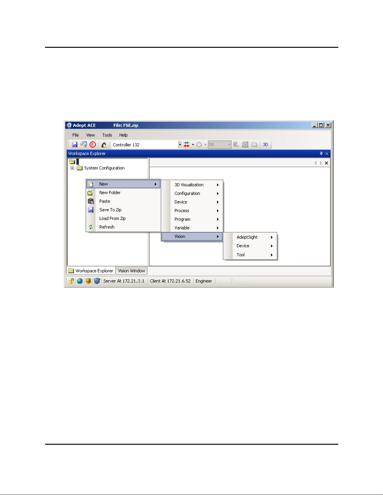
The AdeptSight topics cover everything that appears in the AdeptSight screens after you
right-click in the Tree structure of the AdeptSight Workspace Explorer and select:
New > Vision
The contents of that are as follows:
AdeptSight
AdeptSight Belt Calibration
AdeptSight Camera Calibration
AdeptSight Sequence
Communication Tool
Gripper Offset
Overlap Tool
AdeptSight User's Guide, Version 3.2.x, Updated: 8/23/2012
Page 16
Page 17

Device
Adding a Camera
Adding an Emulation Device
Adding a Virtual Camera
Device
AdeptSight User's Guide, Version 3.2.x, Updated: 8/23/2012
Page 17
Page 18

Tool
Tool
AdeptSight User's Guide, Version 3.2.x, Updated: 8/23/2012
Page 18
Page 19

Arc Caliper
Arc Edge Locator
Arc Finder
Blob Analyzer
Calculated Arc
Calculated Frame
Calculated Line
Calculated Point
Calibration Grid Locator
Caliper
Color Matching
Tool
Custom Vision Tool
Edge Locator
Gripper Clearance Tool
Image Histogram
Image Processing
Image Sampling
Image Sharpness
Inspection
Line Finder
Locator
Locator Model
Pattern Locator
Point Finder
Remote Vision Tool
AdeptSight User's Guide, Version 3.2.x, Updated: 8/23/2012
Page 19
Page 20

Related Topics and Manuals
Related Topics and Manuals
Vision Basics - Resolution on page 632
Calibrations on page 51
Application Samples on page 537
AdeptSight User's Guide
AdeptSight Reference Guide
AdeptSight User's Guide, Version 3.2.x, Updated: 8/23/2012
Page 20
Page 21
Prerequisites
Prerequisites
Hardware
You should be familiar with your robot and its capabilities. In particular, you should know:
l How to power-up the controller
SmartController User's Guide
l How to power-up and perform start-up calibration of the robot, which is explained in
the user guide for your robot
Adept Document Library
l How to power-up and adjust any other devices in the workcell
l The safety requirements of your robot and any other devices that operate in the work-
cell
WARNING: When run carelessly or by inexperienced operators, robots and other motion devices can severely injure personnel and cause equipment damage.
Adept Document Library
l Basic operation and use of the Adept SmartVision EX, if you will be using one
Adept SmartVision EX User's Guide
l Basic operation and use of the optional control pendant, if you will be using one
Adept T2 Pendant User's Guide (for SmartController CX) or Adept T20 Pendant User's
Guide (for SmartController EX)
Software
AdeptSight
You should be familiar with the AdeptSight workspace.
The AdeptSight workspace uses objects to represent items that, when put
together, make up a functioning workcell. The workspace is composed of a hierarchy of objects, both physical (like robots and end-effectors) and non-physical
(like sequences and variable values).
Some objects are created automatically when you connect to a controller (for
example, the controller, robot, and robot grippers). Other objects can be added
to provide increased functionality to the workcell.
AdeptSight User's Guide, Version 3.2.x, Updated: 8/23/2012
Page 21
Page 22

Hardware Installation and Startup
After objects have been added to the AdeptSight workspace, the object editors
are used to edit their parameters.
For more details, refer to AdeptSight User's Guide.
V+
If you will be using V+ to access and execute the AdeptSight tools, you need to
be familiar with the V+ operating system and programming environment. For
details, refer to the V+ user and reference guides in the Adept Document
Library.
Application Samples
The AdeptSight software includes application samples to help you learn the
user interface and get started with basic application development. For more
details, refer to the topic Application Samples on page 537.
Hardware Installation and Startup
Hardware that will be used with the AdeptSight software should already be installed and
tested. Hardware in the following list should be installed before proceeding.
l The robot and any devices that will work in conjunction with the robot
l The robot controller and the following option:
o
Digital I/O
Note that the Cobra i-Series robots do not use an Adept SmartController.
l The vision processor and any of the following accessories:
o
Cameras
o
Lighting or strobes
l Workcell equipment, including:
o
Part feeders
o
Conveyors
o
Connections between the workcell equipment and the digital I/O system
o
Any safety devices needed to prevent injuries during workcell operation
Software Installation and Startup
The AdeptSight User's Guide covers installing the software on your system.
AdeptSight User's Guide, Version 3.2.x, Updated: 8/23/2012
Page 22
Page 23

Related Topics and Manuals
NOTE: The AdeptSight software requires a USB dongle with AdeptSight license to enable
complete functionality. This dongle is included with your AdeptSight or AdeptSight software.
Related Topics and Manuals
User Interface on page 26
Calibrations on page 51
AdeptSight User's Guide
AdeptSight User's Guide, Version 3.2.x, Updated: 8/23/2012
Page 23
Page 24

Vision Overview
Vision Overview
A vision system consists of some means of obtaining an image, and some means of processing that image.
l AdeptSight systems typically uses one or more cameras to capture images for proc-
essing. These images can be stored for later processing, if desired.
l Images are processed with AdeptSight vision tools. See Vision Tools on page 229.
This topic introduces some of the concepts and terms used in the other vision topics.
If you're new to vision guidance/inspection, you should read the section on Vision Basics,
starting with Vision Basics - Resolution on page 632.
Vision Devices
A vision device can be either a physical camera or an emulated camera. Vision devices are
added to the workspace as needed. You can have multiple vision devices in the workspace.
See Vision Devices on page 201.
Physical Camera
AdeptSight supports the following physical cameras:
l Basler 1394a
l Basler 1394b
l Basler GigE
A physical camera needs to be calibrated, to establish the relationship between
physical distance in the camera's field of view and the pixels returned from the
camera. This type of calibration also helps correct for a certain amount of distortion in the lens. This calibration is covered in the section Standalone Camera
Calibration on page 207.
If the camera will be used with a robot and/or conveyor belt, the camera also
needs to be calibrated with respect to those devices. Those are separate calibrations, distinct from the relatively simple distance-pixel calibration. These calibrations are added as objects in the workspace. See AdeptSight Camera
Calibration Interview Wizard on page 75 .
The area that a camera can "see" is called its field of view (FOV).
Emulated Camera (emulation device)
An emulated camera is a collection of stored images that can be used as input,
via a virtual camera, to vision tools. Using an existing image, rather than taking
an image with a camera, can be useful when setting up a new system, or when
AdeptSight User's Guide, Version 3.2.x, Updated: 8/23/2012
Page 24
Page 25

Vision Tools
troubleshooting. Images taken at a system that is having trouble can be sent
to a remote facility for analysis.
Virtual Camera
The interface between AdeptSight and Vision Devices is a virtual camera. Both
physical and emulated cameras require the definition of an associated virtual
camera. This allows AdeptSight to access either type of camera using the same
interface.
Vision Tools
A vision tool is software that performs one or more vision-related operations on its input.
Each tool performs a specific function, such as inspection or some other processing. The input
can be an image from a virtual camera or it can be the output of another vision tool.
NOTE:A new workspace doesn't have any tools in it. You add (create) them in the workspace as needed. See Adding Vision Tools on page 239.
Sequences
The output of one vision tool can be used as the input to another. In this way, the order of
tool execution is implicitly defined. You can add a Sequence object to the workspace, to help
you see the order in which tools will be executed. See AdeptSight Sequence on page 181.
Related Topics
Vision Devices on page 201
Adding Vision Tools on page 239
Calibrations on page 51
AdeptSight User's Guide, Version 3.2.x, Updated: 8/23/2012
Page 25
Page 26
User Interface
User Interface
The Workspace Explorer and the Vision Window are the primary user interfaces to the AdeptSight software.They are both launched from the main AdeptSight window.
Workspace Explorer
The Workspace Explorer Window
The Workspace Explorer provides an interface for displaying information and allowing you to
make changes to Device and Tool configurations.
The left side of the Workspace Explorer is the Tree structure. This allows you to select or add
objects. The remainder of the window is referred to as the Object Editor for the active object.
A tab at the top of the Workspace Explorer indicates which tool or device is active.
For vision tools, the Workspace Explorer typically shows a Display window, a Grid of Results,
and a Configuration window. Refer to the previous figure.
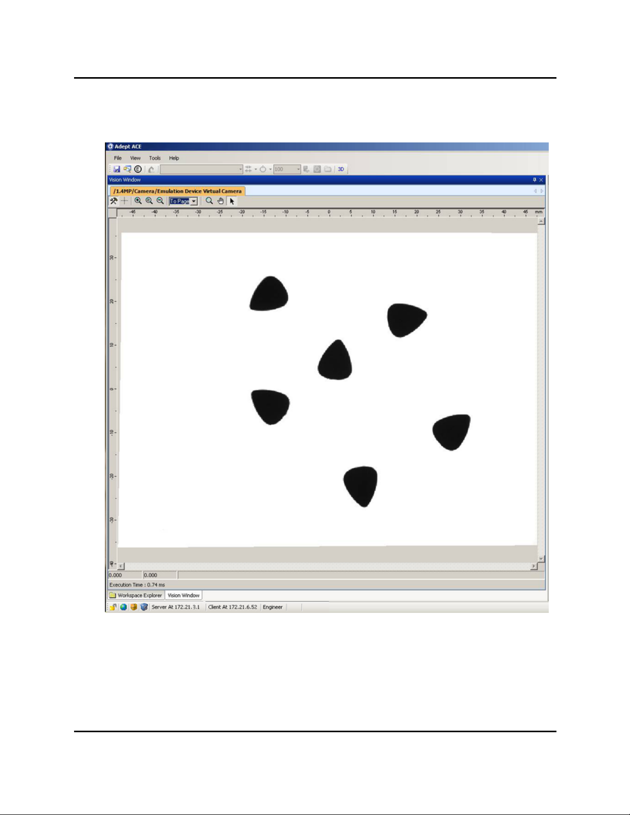
Display Window
The Display window generally shows the image being processed, locations of found instances
on that image, as well as the time of execution, at the bottom of the window.
AdeptSight User's Guide, Version 3.2.x, Updated: 8/23/2012
Page 26
Page 27
Grid of Results
The Display window for an individual tool shows you the results for the tool being edited and
also allows you to edit the region of interest for the tool.
Note that, while the Display window shows the image and results from the tool's latest iteration, the Vision Window is the "runtime display" for the image, and shows cumulative
graphic results of tools executed on it. For more details, see the topic The Vision Window on
page 28.
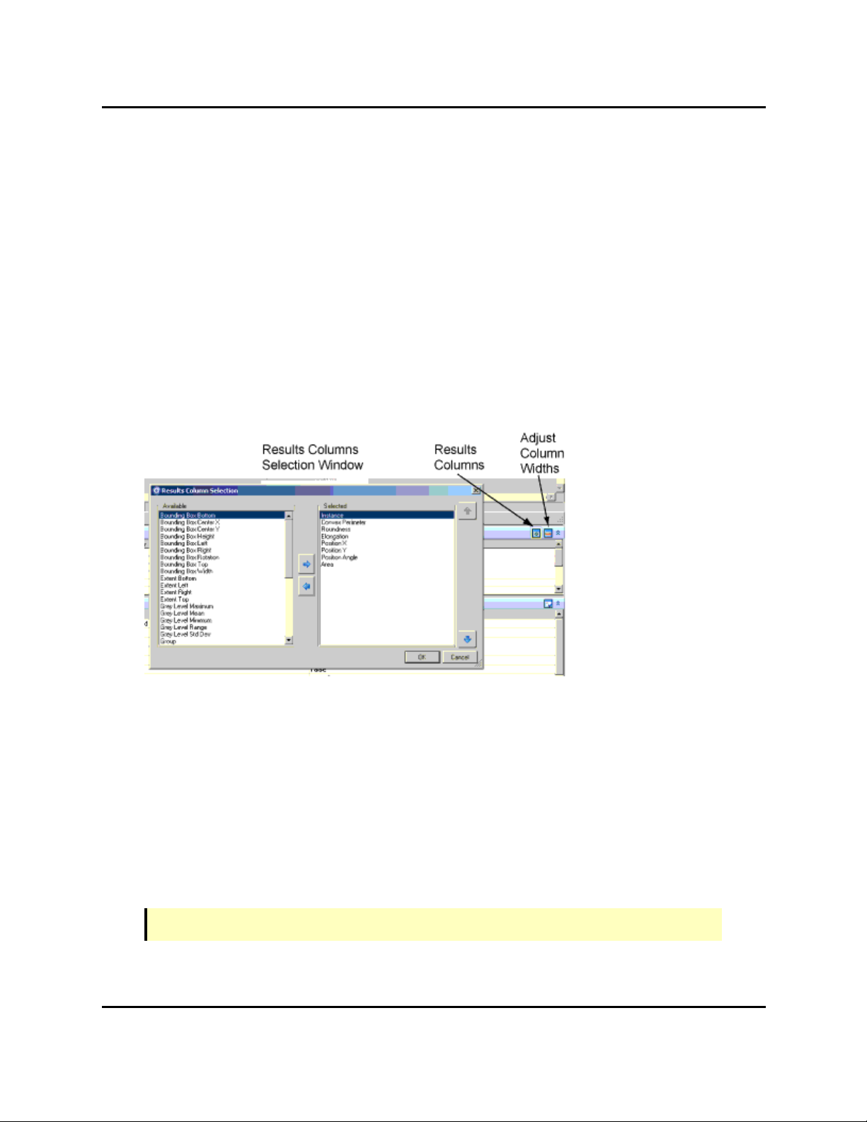
Grid of Results
The Grid of Results displays the values for all the results you have selected to be displayed for
the tool.
Clicking the Results Columns icon displays the window shown in the following figure:
Results Columns Window
The left and right arrows in this window let you select which results will be displayed in the
Grid of Results.
The widths of the columns can be automatically adjusted with the Adjust Column Widths
icon, or you can manually size them with the mouse.
Configuration Window
The Configuration window allows you to modify the behavior of the tool. It typically contains
sections for Properties, Advanced Properties, Region of Interest, and Tool Links.
NOTE:Not all tools will have all of these sections.
AdeptSight User's Guide, Version 3.2.x, Updated: 8/23/2012
Page 27
Page 28
The Vision Window
The Vision Window
The Vision Window
The Vision Window shows the cumulative results of vision operations executed on the vision
buffer. The Vision Window:
AdeptSight User's Guide, Version 3.2.x, Updated: 8/23/2012
Page 28
Page 29

Virtual Cameras
l Displays the images from virtual cameras
l Displays results of image processing tools
l Provides access to images (stored in buffers and represented as tabs in the Vision Win-
dow)
NOTE: The Vision Window is displayed from the Workspace Explorer by selecting
View > Vision Window or by clicking the Vision icon (a camera) in the tool bar at
the top of the Workspace Explorer screen.
Virtual Cameras
A virtual camera is used to represent the output of a physical camera or an emulated camera
(stored image).
l The virtual camera lets AdeptSight software process all images, regardless of their
source, using the same interface.
l The AdeptSight software allows multiple simultaneous virtual cameras.
l Each virtual camera has its own setup and calibration.
Images
Images can be the output of a virtual camera (a photograph taken by a physical camera, or a
stored image), or the output of a vision tool. For instance, the Image Processing and Color
Matching tools output an image, which can be selected as the input to another vision tool.
Each image is stored in a buffer, represented by a tab in the Vision Window, and selectable
from the Vision Window.
When vision tools run, they are executed on the selected image.
AdeptSight User's Guide, Version 3.2.x, Updated: 8/23/2012
Page 29
Page 30
Tabs in the Vision Window
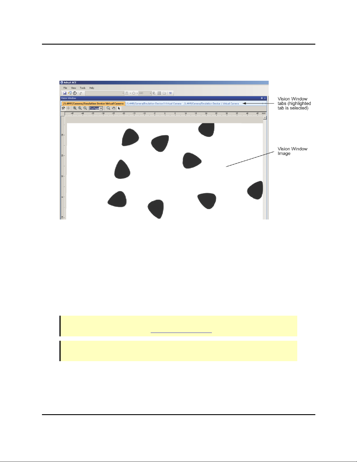
Tabs in the Vision Window
Tabs in the Vision Window - the selected tab determines the image displayed
Tabs are used to represent and access items in the Vision Window, as follows:
l Each virtual camera is represented by a tab in the Vision Window and the Workspace
Explorer.
l Each active vision tool that outputs an image will have a tab in the Vision Window to
display its results (the Image Processing and Color Matching tools output an image).
l The results of the selected vision tool will be displayed in the Vision Window.
3D Visualization Window
NOTE: This feature operates differently in emulation mode. For details on emulation
mode, see Emulation Mode in the Adept ACEUser's Guide.
NOTE: The 3D Visualization feature requires hardware that supports DirectX 9.0c, or
later, and 3D graphics.
The Adept ACE software incorporates Adept’s "3D Visualization" technology, which automatically creates a 3D visualization (simulation) of your system. For example, when you first
connect to the Adept SmartController, the robot automatically appears in the 3D
AdeptSight User's Guide, Version 3.2.x, Updated: 8/23/2012
Page 30
Page 31

3D Visualization Window
Visualization window. If you add a gripper to your robot, the tool offset is added to the 3D display. If you add other objects to the Workspace Explorer and then teach the locations of the
objects, they automatically move to the correct locations in the 3D display. You can even see
representations of your move locations in the 3D Visualization window.
Refer to the Adept ACEUser's Guide for details on the 3D Visualization Window.
Related Topics
Vision Devices on page 201
Adding Vision Tools on page 239
Calibrations on page 51
AdeptSight User's Guide, Version 3.2.x, Updated: 8/23/2012
Page 31
Page 32

Workspace Explorer
Workspace Explorer
The Workspace Explorer is the main work area for the AdeptSight software. You can use it to
add and delete objects, access an object editor, access configuration utilities, and access program editors.
The Workspace Explorer displays the workspace objects in a tree structure on the left side of
the display, and editors for those objects on the right side of the display. Objects include cameras, virtual cameras, robots, controllers, grippers, sequence objects, calibration objects (belt
or camera), and vision tools. Refer to the following figure.
Workspace Explorer Window
AdeptSight User's Guide, Version 3.2.x, Updated: 8/23/2012
Page 32
Page 33

Toolbars
Toolbars
The AdeptSight toolbars provide quick access to frequently-used items (see the following figures). The toolbar icons will be shown (or hidden) based on the licenses available on the USB
hardware key.
Toolbar - General
Toolbar - Connections
Toolbar - Task Status Control
The toolbars can be displayed (or hidden) by selecting View > Toolbars and then selecting
the toolbar(s) you wish to view.
Toolbars Menu
The toolbar items are described below.
NOTE:If a toolbar item is not available, its icon will be dimmed (shown as a gray image).
Toolbar - General
Item Description
Saves the current workspace in the default file (the
last file loaded or selected in the "Save As" dialog
box). Refer to the AdeptSight User's Guide for
details.
AdeptSight User's Guide, Version 3.2.x, Updated: 8/23/2012
Page 33
Page 34

Toolbars
Item Description
Finds text in any of the following objects:
l UI Builder C# code
l C# Program
l C# Custom Allocation Script
l C# Custom Vision Tool
l V+ module program collection
l V+ global variable collection
l Notes
Opens the Edit OPC window.
Opens the Workspace Explorer window. Refer to the
AdeptSight User's Guide for details.
Opens the Task Status Control. Refer to the AdeptSight User's Guide for details.
(3D available)
(3D not available)
Toolbar - Connections
Item Description
Opens the 3D Visualization window. Refer to the
AdeptSight User's Guide for details.
Opens the Watch Variable Tool. Refer to the AdeptSight User's Guide for details.
Opens the AdeptSight Vision window. See the User
Interface on page 26 for details.
Displays any system configuration error messages.
Opens the Robot Jog Control. See the topic Robot and
Teach Controls in the AdeptSight User Guide for
details.
AdeptSight User's Guide, Version 3.2.x, Updated: 8/23/2012
Page 34
Page 35

Toolbars
Item Description
Displays the currently-selected controller. A list of
available controllers can be viewed by clicking the
down arrow ( ).
(not connected)
(connected)
Connects (initiates communication) to the selected
controller. When connected, click to disconnect (stop
communication) from the selected controller. A progress indicator displays the status of the operation:
Connecting Progress Indicator
You can connect/disconnect from ALLcontrollers in
the system by selecting the "All" option.
AdeptSight User's Guide, Version 3.2.x, Updated: 8/23/2012
Page 35
Page 36

Toolbars
Item Description
(not enabled)
(enabled, not cal-
ibrated)
(enabled, calibrated)
DANGER:The robot may move during the enable power/calibration procedure. Make certain that the work
cell is clear of all personnel and
obstacles so that the robot does not
cause death/injury or damage
when moving.
Enables high power to the controller/robot and indicates the calibration state of the robot.
NOTE:For most systems, after the icon is clicked,
you are required to press and release the High
Power button (a physical button located on the
external front panel) within 10 seconds. If this is
not done in the required time, High Power is not
enabled and an error message is displayed.
See your Adept robot user's guide for more details
on enabling high power.
A progress indicator displays the status of the
operation:
Enable/Disable Power Progress Indicator
After enabling high power, the system will automatically calibrate the robot, if needed.
When enabled, click to disable high power to the controller/robot (icon turns red).
You can enable/disable high power to
ALLcontrollers/robots in the system by selecting the
"All" option.
AdeptSight User's Guide, Version 3.2.x, Updated: 8/23/2012
Page 36
Page 37

Item Description
Toolbar - Task Status Control
Toolbars
Displays the current monitor speed. To change the
monitor speed, select it from the drop-down list, or
type the desired value into the field, and press Enter.
Opens the Monitor windows. Refer to the AdeptSight
User's Guide for details.
Opens the Controller Development Tools windows.
Refer to the AdeptSight User's Guide for details.
Opens the Digital I/O control. Refer to the AdeptSight
User's Guide for details.
Opens the File Explorer Manager, which is used to view
files/folders on the controller.
NOTE:This toolbar provides quick access to specific Task Status controls. This includes
Process Managers, C# Programs, and AdeptSight Sequences. For additional controls,
status messages, and other task control features, use the Task Status Control. Refer to
the AdeptSight User's Guide for details.
Item Description
Displays the currently-selected task. A list of available processes can be viewed by clicking the down
arrow ( ). Refer to the AdeptSight User's Guide for
details.
Starts (executes) the selected task.
Enabled during execution, pauses or exceptions,
this button causes the execution to stop for the
selected task.
Item Description
Displays the currently-selected process. A list of
available processes can be viewed by clicking the
down arrow ( ).
AdeptSight User's Guide, Version 3.2.x, Updated: 8/23/2012
Page 37
Page 38

Shortcut Menus
Shortcut Menus
Right-clicking on an object in the Tree structure of the Workspace Explorer opens a shortcut
menu, as shown in the following example.
Example Object Shortcut Menus
Right-clicking on an empty area in the Tree structure opens an abbreviated short-cut menu,
with just those items that don't operate on a specific file.
The shortcut menu items will vary, depending on the object that is selected. The following is
a description of the shortcut menu items:
Item Description
New… Adds new objects.
New Folder Creates a new folder under the current folder.
Delete Deletes the selected object or folder.
Rename Renames the selected object or folder.
Copy Copies the selected object or folder to the clipboard as XML
data.
AdeptSight User's Guide, Version 3.2.x, Updated: 8/23/2012
Page 38
Page 39

Shortcut Menus
Item Description
Duplicate Creates a copy of the selected object in its current folder. A
number appended to the end of the name for the duplicated object.
Links to Other Objects Shows all references to the specified object or folder in the
workspace.
Paste Pastes an object or folder from the clipboard. A number
appended to the end of the name for the pasted object.
Save To File Saves the selected folder or object to a file. You can save
the file in ZIP or AWP format.
Load From File Loads a folder or object from a file. You can load a file that
has been saved in ZIP or AWP format.
Refresh Refreshes the display of the selected object or folder. The
F5 key also refreshes the selected object or folder.
Tree Structure Toolbar Icons
The Tree structure of the Workspace Explorer contains a set of toolbar icons, which are used
for managing the objects and folders.
Tree Structure Toolbar
NOTE:In addition to the Tree structure toolbar, the Workspace Explorer also contains a
main toolbar. Refer to the AdeptSight User's Guide for details.
The following is a description of the toolbar items.
AdeptSight User's Guide, Version 3.2.x, Updated: 8/23/2012
Page 39
Page 40

Shortcut Menus
Icon Description
Opens the Create a New Object dialog, which is used to add a new object
to the workspace. For more details on adding new objects to the workspace, refer to the AdeptSight User's Guide.
Adds a new folder to the workspace.
Deletes the selected item.
Copies the selected item.
Pastes the previously-copied item.
AdeptSight User's Guide, Version 3.2.x, Updated: 8/23/2012
Page 40
Page 41

Object Editors
Icon Description
Opens the Links to Other Objects window, which displays the Incoming
and Outgoing linked objects for the selected object. You can double-click
any link to open the corresponding editor for the linked object. For more
details on editing objects, refer to the AdeptSight User's Guide.
Refreshes (updates) the list of items in the Tree structure of the Workspace Explorer. The F5 key also refreshes the selected object or folder.
Object Editors
Double-click an object in the Tree Structure of the Workspace Explorer to open its editor.
NOTE:Objects can be dragged and dropped from the Tree structure into other active windows.
AdeptSight User's Guide, Version 3.2.x, Updated: 8/23/2012
Page 41
Page 42

Object Editors
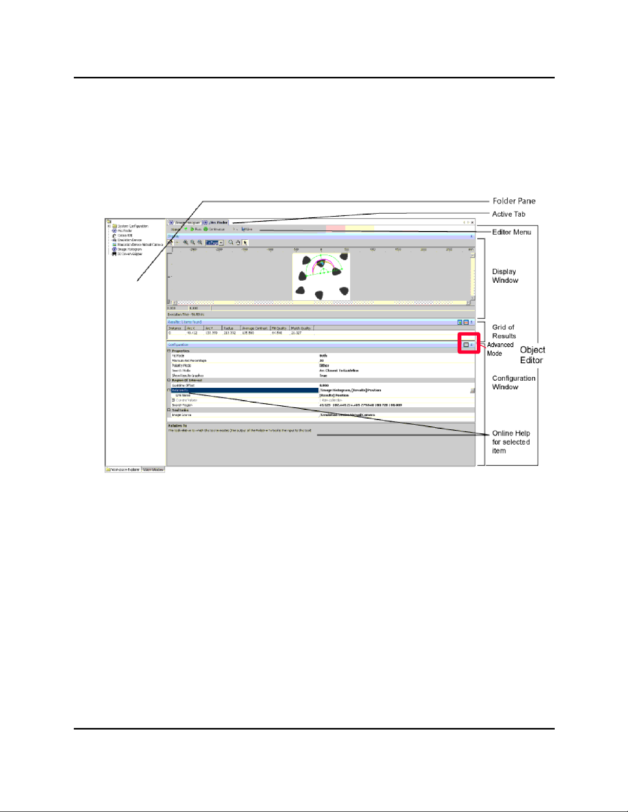
Workspace Explorer with Arc Finder Editor
Most object editors include one or more of the following items:
Item Description
Editor name Displays the name and path of the current editor, as a
tab
Menu Menu contents will vary, depending on which editor is
open
Display window Graphic display of the image results, as well as
elapsed/execution time for the tool
Grid of Results Non-graphical results of the tool
Configuration window Used to select and enter values for each item. For most
editors, items are grouped; a group can be expanded or
collapsed using the '+' or '-' symbol next to the group
heading
Online help Provides help for the selected editor item
AdeptSight User's Guide, Version 3.2.x, Updated: 8/23/2012
Page 42
Page 43

Dockable Editor Windows
Object editors for vision tools usually have a Display window (not the same as the Vision Window), a Results window, and a Configuration Window. Refer to the previous figure.
Dockable Editor Windows
The AdeptSight workspace is designed so you can position (dock) multiple editor windows
within the same workspace, as shown in the following figure. This feature allows you to customize the editing environment for your application.
Multiple Windows
To dock multiple editor windows in the workspace:
1. Open the object editors you wish to use.
The object editors are shown in a "stacked" configuration. The tabs at the top of the
window allow you to select the editor you wish to view.
AdeptSight User's Guide, Version 3.2.x, Updated: 8/23/2012
Page 43
Page 44

Dockable Editor Windows
Editor Window Tabs
2. Click and hold the tab at the top of the editor window to select it.
3. Drag the tab into the workspace.
Window position locators are displayed that you can use to position the selected editor
within the workspace window.
Window Position Locators
4. Drop the tab onto the desired position locator and release.
The editor window is repositioned in the workspace window.
5. Repeat these steps until all editor windows are positioned as desired.
AdeptSight User's Guide, Version 3.2.x, Updated: 8/23/2012
Page 44
Page 45

Editor Window Management
Editor Window Management
When working with multiple editor windows, you can right-click on any object editor tab to
display a menu containing window-management functions. The following figure shows a
menu along with a description of each function.
Close
Closes the selected object editor
Close All
Closes all object editors that are currently open
Close All But This
Closes all object editors that are currently open except the selected editor
Prominent
Resizes the selected object editor to
fill the current window
Rebalance
Resizes the object editors within a tab
group, so that all the editors are the
same size. Resizes the tab groups
within the Workspace Explorer, so
that all tab groups are the same size.
New Horizontal Tab Group
Splits the current tab group horizontally, and moves the selected tab
to the new tab group
New Vertical Tab Group
Splits the current tab group vertically, and moves the selected tab to
the new tab group
Move to Next/Previous Tab
Group
Moves the selected tab to the next or
previous tab group. If the current tab
group has only one tab, this collapses
that tab group.
Move to View
When multiple View tabs are available, you can use this menu item to
move the selected tab into a different
View tab. For more details on using
AdeptSight User's Guide, Version 3.2.x, Updated: 8/23/2012
Page 45
Page 46

Editor Window Management
View tabs, see View Tabs on page 46.
Move to New View
Creates a new view tab and then
moves the selected object editor to
that tab. For more details on using
View tabs, see View Tabs on page 46.
View Tabs
In addition to the editor management features described in the previous section, the AdeptSight software
includes a "View tab" feature that allows you to assign objects to tabs in the object editor pane of the Workspace Explorer window.
Creating a New View Tab
When you first open the AdeptSight software, there is one View tab displayed, which is followed by three
dots (...), as shown in the following figure.
Default View Tab
To create a new tab, simply click the three dots (...) and a new tab is added, as shown in the following figure.
Multiple View Tabs
After a tab is created, you can double-click an object in the Tree structure to open it in the selected tab. You
can have multiple objects open in a tab.
Renaming a View Tab
To rename a tab, double-click on the tab you wish to rename. The Edit View Name dialog opens.
Edit View Name Dialog
AdeptSight User's Guide, Version 3.2.x, Updated: 8/23/2012
Page 46
Page 47

Editor Window Management
Type the new name and then click OK. The dialog closes and the new name is assigned to the tab.
Closing a View Tab
To close a tab, select the tab and then click the X icon in the bottom right-hand corner. The selected tab
closes.
AdeptSight User's Guide, Version 3.2.x, Updated: 8/23/2012
Page 47
Page 48

Calibration Overview
Calibration Overview
The AdeptSight software provides three types of calibration. The calibrations must be performed in the following order:
l Basic camera calibration
l AdeptSight Belt Calibration Wizard - only needed if you will be using a conveyor belt in
the system
l AdeptSight Camera Calibration Wizard
l AdeptSight Latch Calibration Wizard
Basic Camera Calibration
This makes the system aware of the relationship between each pixel of the camera and absolute size in the field of view.
See Standalone Camera Calibration on page 207 .
AdeptSight Belt Calibration
This calibrates a conveyor belt to a robot.
See AdeptSight Belt Calibration on page 55.
AdeptSight Camera Calibration
This calibrates a camera to a robot, making the system aware of the location of
the field of view with respect to the robot.
See AdeptSight Camera Calibration on page 73.
AdeptSight Latch Calibration
This calibrates a latch to a robot.
See Latch Calibration.
Related Topics
Calibrations on page 51
AdeptSight User's Guide, Version 3.2.x, Updated: 8/23/2012
Page 48
Page 49

Special Tools Overview
Special Tools Overview
AdeptSight software provides several tools for special applications.
Sequence
The Sequence object shows the list of tools that will be executed as part of the sequence and
the order in which they will be executed. It also maps a V+ sequence number to the “toplevel” vision tool. "Top-level" means the last tool executed. This enables you to access an
AdeptSight sequence with the sequence_id parameter from a V+ program instruction or function. See AdeptSight Sequence on page 181.
OverlapTool
The Overlap Tool ensures that the AdeptSight system does not try to handle the same part
twice. This is generally placed before another tool, to be sure that the second tool processes
each part only one time. See Overlap Tool on page 193Overlap Tool on page 193.
Communication Tool
The Communication Tool determines how parts are distributed between the controller and
the next vision tool in the sequence. This gives you the ability to decide how to respond when
there are too many parts for a single robot to process. See Communication Tool on page 183
and Configuring Communication Tool Properties on page 189.
Related Topics
AdeptSight Special Tools on page 179
AdeptSight User's Guide, Version 3.2.x, Updated: 8/23/2012
Page 49
Page 50

Safety Conventions and Getting Help
Safety Conventions and Getting Help
Three levels of safety notation are used in this manual. In descending order of importance,
they are:
WARNING: If the actions indicated in a warning are not complied
with, injury or major equipment damage could result. A warning typically describes the potential hazard, its possible effect, and the measures that must be taken to reduce the hazard.
CAUTION: If the action specified in a caution is not complied with,
damage to your equipment or data could result.
NOTE: A note provides additional information, emphasizes or supplements a point or procedure, or gives a tip for easier operation.
How Can I Get Help?
For details on getting assistance with your Adept software or hardware, you can access the
following information sources on the Adept corporate website:
l For contact information: http://www.adept.com/contact/americas
l For product pupport information: http://www.adept.com/support/service-and-sup-
port/main
l For user discussions, support, and programming examples:
http://www.adept.com/forum/
l For further information about Adept Technology, Inc.: http://www.adept.com
Refer to the How to Get Help Resource Guide (Adept P/N 00961-00700) for details on getting
assistance with your Adept software or hardware.
Related Topics and Manuals
Adept Document Library
AdeptSight User's Guide
AdeptSight User's Guide, Version 3.2.x, Updated: 8/23/2012
Page 50
Page 51

Calibrations
Calibrations
This section covers two basic calibrations:
l Belt-to-robot calibration
l Camera-to-robot calibration
NOTE:The Basic camera calibration should have already been performed. See
Standalone Camera Calibration.
When do I Calibrate?
Calibration needs to be performed once for each different setup. If you make changes to the
setup, specifically to the robot, belt, or camera position, parameters, or configuration, then
you must recalibrate the new setup.
What Order?
NOTE:All devices being calibrated must be connected and functioning properly.
1. AdeptSight Belt Calibration: This calibrates a conveyor belt to a robot.
It consists of an interview wizard followed by a calibration wizard.
You must run this calibration before the AdeptSight Camera Calibration.
NOTE:AdeptSight Belt Calibration is not needed if there is no conveyor belt in the
system.
When the AdeptSight Belt Calibration is completed, a Belt Calibration object is
created, which will be needed for the AdeptSight Camera Calibration.
For details, see AdeptSight Belt Calibration on page 55.
2. AdeptSight Camera Calibration: This calibrates a camera to a robot, making the system aware of the location of the camera's field of view with respect to the robot.
It consists of an interview wizard followed by a calibration wizard.
When the AdeptSight Camera Calibration is completed, AdeptSight generates an
AdeptSight Camera Calibration object.
For details, see AdeptSight Camera Calibration on page 73.
The calibration interview wizards gather sufficient information about your system to use the
correct parameters during their respective calibration wizards.
AdeptSight User's Guide, Version 3.2.x, Updated: 8/23/2012
Page 51
Page 52

Wizard Screens
Wizard Screens
The AdeptSight Belt Calibration Wizard and AdeptSight Camera Calibration Wizard use similar
formats.
A sample calibration wizard screen is illustrated in the following screen shot:
Sample Calibration Interview Wizard Screen
Wizard Name
The title in the blue bar identifies which wizard is executing. It is the context of
the screen. In the example, this is "AdeptSight Robot-to-Camera Calibration
Wizard".
Task
The heading tells you what you will be doing in this screen: "Camera Mount
Type Selection".
Action
The line under the task heading tells you what you must do, or poses the question that this task will answer: "Select the type of camera mount".
Action Details
If needed, details are given in the inner window:"Select the camera mount
type".
At the bottom of the Wizard screens you will usually find I/O, Power, Previous, Next, Can-
cel, and Help buttons.
AdeptSight User's Guide, Version 3.2.x, Updated: 8/23/2012
Page 52
Page 53

Related Topics
Some of these, particularly Previous, may be greyed-out when that action is not appropriate. (Many procedures require that you click Cancel and start over, rather than backing
up with Previous.)
Related Topics
Standalone Camera Calibration on page 207
AdeptSight Belt Calibration Interview Wizard on page 59
AdeptSight Belt Calibration Wizard on page 65
AdeptSight Camera Calibration Interview Wizard on page 75
AdeptSight Camera Calibration Wizard - Automated, no Belt on page 85
AdeptSight Camera Calibration Wizard - Automated, with Belt on page 97
AdeptSight Camera Calibration Wizard - Automated Upward-Looking on page 121
AdeptSight Camera Calibration Wizard - Automated, Arm-Mount on page 109
AdeptSight Camera Calibration Wizard - Manual, no Belt on page 131
AdeptSight Camera Calibration Wizard - Manual with Belt on page 141
AdeptSight Camera Calibration Wizard - Manual, Upward-looking on page 167
AdeptSight Camera Calibration Wizard - Manual, Arm-Mount on page 153
AdeptSight User's Guide, Version 3.2.x, Updated: 8/23/2012
Page 53
Page 54

Page 55

AdeptSight Belt Calibration
AdeptSight Belt Calibration
AdeptSight Belt Calibration calibrates a robot to a conveyor belt.
This calibration is necessary when the robot will handle parts that are moving on a conveyor
belt. These are referred to as conveyor-tracking applications.
This calibration is available in Emulation Mode.
Requirements
l The robot, controller, and belt must be correctly connected and functioning.
l The PC running the AdeptSight software must be connected to the controller for the
robot and belt.
l The belt, as well as the robot and gripper, must be defined in the AdeptSight software.
To add a belt to the Workspace, right-click in the Tree structure of the Workspace
Explorer and select:
New > Process > Belt.
AdeptSight User's Guide, Version 3.2.x, Updated: 8/23/2012
Page 55
Page 56

Requirements
Adding a Belt Object
In the Belt Object Editor:
1. Click Add (under Encoders).
2. Click Associate. See the following figure.
AdeptSight User's Guide, Version 3.2.x, Updated: 8/23/2012
Page 56
Page 57

Next Steps
Add and Associate Buttons
3. Click the controller, to select it.
The selected controller will be highlighted.
4. Click OK.
Next Steps
Run the AdeptSight Belt Calibration Interview Wizard (for details, see AdeptSight Belt Calibration Interview Wizard on page 59), then the AdeptSight Belt Calibration Wizard (for
details, see AdeptSight Belt Calibration Wizard on page 65).
Related Topics
Calibration Overview on page 48
AdeptSight Belt Calibration Interview Wizard on page 59
AdeptSight Belt Calibration Wizard on page 65
AdeptSight Camera Calibration Interview Wizard on page 75
AdeptSight Camera Calibration Wizard - Automated, with Belt on page 97
AdeptSight Camera Calibration Wizard - Automated, no Belt on page 85
AdeptSight Camera Calibration Wizard - Automated Upward-Looking on page 121
AdeptSight Camera Calibration Wizard - Manual, no Belt on page 131
AdeptSight Camera Calibration Wizard - Manual with Belt on page 141
AdeptSight Camera Calibration Wizard - Manual, Upward-looking on page 167
AdeptSight User's Guide, Version 3.2.x, Updated: 8/23/2012
Page 57
Page 58

Page 59

AdeptSight Belt Calibration Interview Wizard
AdeptSight Belt Calibration Interview Wizard
The Belt Calibration Interview Wizard gathers the parameters necessary for you to run the
AdeptSight Belt Calibration Wizard. It does not automatically run that wizard.
To run the interview wizard, right-click in the Tree structure of the Workspace Explorer and
select:
New > Vision > AdeptSight > AdeptSight Belt Calibration
Procedure
All screens havethe title "AdeptSight Robot-to-Belt Calibration Wizard".
A list of tasks that will be performed is displayed in the left pane as you go through the calibration:
List of Wizard Tasks
The screens in this procedure are:
l Welcome
AdeptSight User's Guide, Version 3.2.x, Updated: 8/23/2012
Page 59
Page 60

Procedure
Belt Calibration Welcome Screen
Click Next.
l Robot Selection for Calibration
Select the robot that will be used for this calibration.
1. Click on the browse icon to display a list of available robots.
2. Select the robot that you wish to use.
3. Click OK.
4. Click Next.
l End-Effector Selection for Calibration
NOTE:This will default to the end-effector of the selected robot.
Select the end-effector of the selected robot.
1. Click on the browse icon to display a list of available end-effectors.
2. Select the end-effector that you wish to use.
3. Click OK.
4. Click Next.
l End-effector Signals
Set the I/O signal values for the selected end-effector.
AdeptSight User's Guide, Version 3.2.x, Updated: 8/23/2012
Page 60
Page 61

Procedure
Setting the End-effector Signal Values
Green indicates an enabled signal. Black indicates a disabled signal. Yellow in a text
field indicates an invalid value.
NOTE:These signals need to be set for the Belt Calibration Wizard to work, since
you will need to be able to move the belt with them.
l Select existing or new camera
The wizard will let you add a new camera at this point if you choose to.
l Camera properties
Edit these, if needed. Refer to Camera Properties on page 223.
AdeptSight User's Guide, Version 3.2.x, Updated: 8/23/2012
Page 61
Page 62

Procedure
Setting the Camera Properties
l Launch Grid Calibration
AdeptSight User's Guide, Version 3.2.x, Updated: 8/23/2012
Page 62
Page 63

Procedure
Launching the Grid Calibration
You will need a grid of dots for this calibration. Refer to Standalone Camera Calibration
on page 207.
l Select the encoder
The SmartController's only required connection with a conveyor belt is the belt's
encoder. In some installations, the controller will have control over belt motion.
Selecting the Encoder
l Turn on power
l Teach Picture-taking Position
l Teach the Vision tool
l Interview completed
AdeptSight User's Guide, Version 3.2.x, Updated: 8/23/2012
Page 63
Page 64

Next Step
Next Step
You can now run the AdeptSight Belt Calibration Wizard. For details, see AdeptSight Belt Calibration Wizard on page 65.
Related Topics
Calibration Overview on page 48
AdeptSight Belt Calibration on page 55
AdeptSight Belt Calibration Wizard on page 65
AdeptSight Camera Calibration Interview Wizard on page 75
AdeptSight Camera Calibration Wizard - Automated, no Belt on page 85
AdeptSight Camera Calibration Wizard - Automated, with Belt on page 97
AdeptSight Camera Calibration Wizard - Automated Upward-Looking on page 121
AdeptSight Camera Calibration Wizard - Manual, no Belt on page 131
AdeptSight User's Guide, Version 3.2.x, Updated: 8/23/2012
Page 64
Page 65

AdeptSight Belt Calibration Wizard
AdeptSight Belt Calibration Wizard
After the AdeptSight Belt Calibration Interview Wizard completes, it opens the Object editor
for the AdeptSight Belt Calibration. The toolbar contains buttons for accessing the calibration
wizard and testing the calibration. These procedures are described in the following sections.
AdeptSight Belt Calibration Object Editor
Using the AdeptSight Belt Calibration Wizard
The AdeptSight Belt Calibration Wizard calibrates a robot to a conveyor belt. The output of
this wizard will be a Belt Calibration object.
Launching the Calibration Wizard
AdeptSight User's Guide, Version 3.2.x, Updated: 8/23/2012
Page 65
Page 66

Procedure
Requirements
l The robot and belt must be correctly connected and functioning.
l The AdeptSight Belt Calibration Interview Wizard must have completed successfully.
What this Wizard Does
This calibration is necessary when the robot will handle parts that are moving on a conveyor
belt.
With this wizard you will:
l Establish the relationship between the belt, its encoder, and the robot
l Specify the upstream and downstream limits on the belt
l Specify the downstream pick limit on the belt
l Establish the usable width of the belt
Procedure
All screens have the title "Robot-to-Belt Calibration Sequence".
The screens in this procedure are:
l Select End-effector
l Test Encoder Operation
This lets you confirm that the belt encoder is communicating with the controller.
AdeptSight User's Guide, Version 3.2.x, Updated: 8/23/2012
Page 66
Page 67

Procedure
Testing the Encoder Operation
You can click On/Off to move the belt. You need to have set the I/O values in the Interview Wizard.
AdeptSight User's Guide, Version 3.2.x, Updated: 8/23/2012
Page 67
Page 68

Procedure
l Teach Upstream Limit (#1 in the following figure)
Upstream, Downstream, and Downstream Pick Limits
Upstream limit is the farthest point, towards the start of the belt, that the robot is
allowed to move. This teaches the upstream limit, as well as the far side of the belt,
width-wise (away from the robot).
The target should be taped or otherwise fastened to the belt to prevent the target
from moving, in relation to the belt, during calibration.
AdeptSight User's Guide, Version 3.2.x, Updated: 8/23/2012
Page 68
Page 69

Procedure
1. Place the target on the belt at the upstream limit, away from the robot
(widthwise on the belt).
If the robot is mounted above the belt, and is centered on the belt, pick either
side of the belt.
2. Move the robot tip to the target.
Click Pendant to display the pendant window. This lets you to move the robot,
to center the tip over the target.
3. Click Here.
l Teach Downstream Limit (#2 in preceding figure)
Downstream limit is the farthest point, towards the end of the belt, that the robot is
allowed to move.
1. Move the belt, without touching the target, so that the target stops at the
downstream limit.
2. Move the robot to the target.
3. Click Here.
l Teach Downstream Pick Limit (#3 in preceding figure)
Downstream pick limit is the farthest point, towards the downstream limit, that the
robot is allowed to pick an object. It will be between the upstream and downstream limits. This also teaches the near side of the belt, width-wise (nearest the robot). The difference between the far side and near side establishes the usable width of the belt.
1. Place the target at the downstream pick point, near the robot (widthwise on
the belt).
If the robot is mounted above the belt, and is centered on the belt, pick the side
of the belt opposite from the side you picked before.
2. Move the robot to the target.
3. Click Here.
l Test Calibration
1. Close the Pendant window (click Cancel).
NOTE:This procedure will fail if the Pendant window is left open.
2. Center the robot tool tip over a part on the belt.
3. Click Start Tracking.
AdeptSight User's Guide, Version 3.2.x, Updated: 8/23/2012
Page 69
Page 70

Testing the Calibration
4. Advance the belt.
The robot should track the part on the belt.
Testing the Calibration
The test procedure repeats the test performed at the end of the belt calibration wizard.
Testing the Calibration
1. Close the Pendant window, if it is open (click Cancel).
2. Click Start Tracking.
3. Place a part under the robot.
4. Advance the belt.
The robot should track the part.
Related Topics
Calibrations on page 51
AdeptSight Belt Calibration on page 55
AdeptSight Belt Calibration Interview Wizard on page 59
AdeptSight Camera Calibration Interview Wizard on page 75
AdeptSight Camera Calibration Wizard - Automated, no Belt on page 85
AdeptSight Camera Calibration Wizard - Automated, with Belt on page 97
AdeptSight Camera Calibration Wizard - Automated, Arm-Mount on page 109
AdeptSight Camera Calibration Wizard - Automated Upward-Looking on page 121
AdeptSight User's Guide, Version 3.2.x, Updated: 8/23/2012
Page 70
Page 71

Related Topics
AdeptSight Camera Calibration Wizard - Manual, no Belt on page 131
AdeptSight Camera Calibration Wizard - Manual with Belt on page 141
AdeptSight Camera Calibration Wizard - Manual, Arm-Mount on page 153
AdeptSight Camera Calibration Wizard - Manual, Upward-looking on page 167
AdeptSight User's Guide, Version 3.2.x, Updated: 8/23/2012
Page 71
Page 72

Page 73

AdeptSight Camera Calibration
AdeptSight Camera Calibration
AdeptSight Camera Calibration calibrates a robot to a camera. This calibration is necessary if
you will be using vision with a robot.
Because there are a number of ways to mount a camera, and the option of a conveyor belt,
there are eight different camera calibration wizards.
Requirements
l The robot, controller, belt (if used), and camera must be correctly connected and func-
tioning.
The Cobra i-Series robots do not need a SmartController motion controller.
l The camera itself must be calibrated. See Standalone Camera Calibration on page
207.
l The PC running the AdeptSight software must be connected to the controller for the
robot (and belt).
l The AdeptSight Belt Calibration Wizard must have completed successfully, if a con-
veyor belt will be used (a belt calibration object must exist in the workspace). See
AdeptSight Belt Calibration on page 55.
Next Step
Run the AdeptSight Camera Calibration Interview Wizard. See AdeptSight Camera Calibration Interview Wizard on page 75.
Related Topics
Calibrations on page 51
AdeptSight Belt Calibration on page 55
AdeptSight Camera Calibration Interview Wizard on page 75
AdeptSight Camera Calibration Wizard - Automated, no Belt on page 85
AdeptSight Camera Calibration Wizard - Automated, with Belt on page 97
AdeptSight Camera Calibration Wizard - Automated Upward-Looking on page 121
AdeptSight Camera Calibration Wizard - Automated, Arm-Mount on page 109
AdeptSight Camera Calibration Wizard - Manual, no Belt on page 131
AdeptSight Camera Calibration Wizard - Manual with Belt on page 141
AdeptSight Camera Calibration Wizard - Manual, Upward-looking on page 167
AdeptSight Camera Calibration Wizard - Manual, Arm-Mount on page 153
AdeptSight User's Guide, Version 3.2.x, Updated: 8/23/2012
Page 73
Page 74

Page 75

AdeptSight Camera Calibration Interview Wizard
AdeptSight Camera Calibration Interview Wizard
The AdeptSight Camera Calibration Interview Wizard acquires the data necessary to generate the correct AdeptSight Camera Calibration Wizard. It does not automatically run that
wizard.
What this Wizard Does
With this wizard you will:
l Select the robot, gripper, and virtual camera
l Specify the camera mounting (fixed-mounted, arm-mounted)
Requirements
l The robot and camera must be correctly connected and functioning.
l The camera itself must be calibrated. See Standalone Camera Calibration on page
207.
l The AdeptSight Belt Calibration Wizard must have completed successfully, if a belt will
be used.
Procedure
To add an AdeptSight Calibration Object to the workspace, right-click in the Tree structure of
the Workspace Explorer and select:
New > Vision > AdeptSight > AdeptSight Camera Calibration
All screens have the title "AdeptSight Robot-to-Camera Calibration Wizard".
A list of tasks that will be performed is displayed in the left pane as you go through the calibration:
AdeptSight User's Guide, Version 3.2.x, Updated: 8/23/2012
Page 75
Page 76

AdeptSight Camera Calibration Interview Wizard
List of Wizard Tasks
The screens in this procedure are:
l Welcome to the Calibration Interview Wizard
Camera Calibration Welcome Screen
AdeptSight User's Guide, Version 3.2.x, Updated: 8/23/2012
Page 76
Page 77

AdeptSight Camera Calibration Interview Wizard
l Robot Selection for Calibration
Select the robot that will be used for this calibration.
1. Click on the browse icon to display a list of available robots.
2. Select the robot that you wish to use.
3. Click OK.
4. Click Next.
l End-Effector Selection for Calibration
NOTE:This will default to the end-effector of the selected robot.
Select the end-effector that will be used for this calibration.
1. Click on the browse icon to display a list of available end-effectors.
2. Select the end-effector that you wish to use.
3. Click OK.
4. Click Next.
l Camera Selection for Calibration
Select the camera that will be used for this calibration.
1. Click on the browse icon to display a list of available cameras.
AdeptSight User's Guide, Version 3.2.x, Updated: 8/23/2012
Page 77
Page 78
AdeptSight Camera Calibration Interview Wizard
2. Select the camera that you wish to use.
3. Click OK.
4. Click Next.
l Choose Interview Mode
Specify either:
o
Answer questions and let the wizard select the correct scenario (Recommended)
or
o
Select the correct calibration options from a list
If you chose to answer the wizard's questions, the following information will be requested:
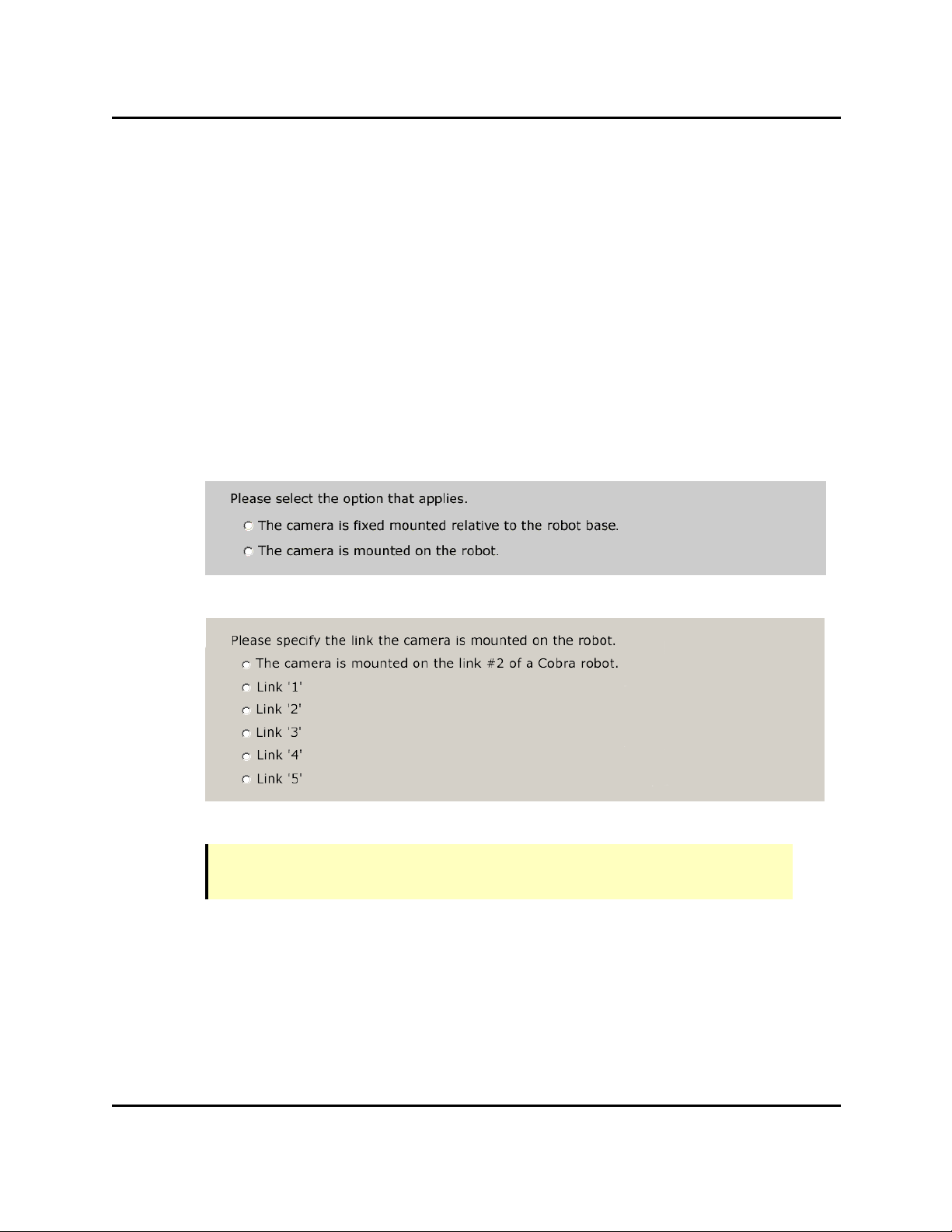
l Specify Camera Mount Type
l Define the camera link (arm-mount only)
l Will a conveyor be part of this calibration? (fixed-mount only)
NOTE:If you have a belt that hasn't been calibrated, you will not be able to complete this camera calibration.
Answering Yes to this includes the belt in the camera calibration.
l What is the interaction with the calibration object? (fixed-mount only)
AdeptSight User's Guide, Version 3.2.x, Updated: 8/23/2012
Page 78
Page 79

AdeptSight Camera Calibration Interview Wizard
l Specify End-Effector Type
l Is the Robot Free to Move?
o
Robot can move freely in workspace
NOTE:This will run the calibration in Automated mode.
o
There are obstacles in the workspace or the work surface is not parallel to the
robot XY plane. I want to move the robot manually.
NOTE: This will run the calibration in Manual mode.
l Allow End-Effector Rotation
l Select the Robot-to-Belt Calibration (conveyor belt systems only)
Select the AdeptSight Belt Calibration object, generated when you ran the Belt Calibration Wizard.
NOTE:If you did not run the AdeptSight Belt Calibration before this calibration,
there will be no Belt Calibration object, and this interview will fail here if you said
that there would be a conveyor belt as part of this calibration.
AdeptSight User's Guide, Version 3.2.x, Updated: 8/23/2012
Page 79
Page 80

AdeptSight Camera Calibration Interview Wizard
If you chose to select the calibration options from a list, you will be presented a screen similar
to the following:
Specifying Calibration Options from a List
1. Specify how the camera is mounted.
2. Specify whether a conveyor belt is to be used.
3. Specify if the calibration object is attached to the robot tool, or picked or
pointed to.
4. Specify whether the robot can pick an object or point to an object.
5. Specify if there are obstacles within the workspace that must be
AdeptSight User's Guide, Version 3.2.x, Updated: 8/23/2012
Page 80
Page 81

AdeptSight Camera Calibration Interview Wizard
considered.
6. Specify whether the tool should rotate during calibration.
l Interview Completed
There are a number of fields that are not covered in the interview wizard. These are usually
left at their defaults, but you can change their values if needed.
Vision Parameters
These parameters specify what vision tools are used in the calibration process.
Calibration Target Size
When using a user-defined vision tool, the size of the target, in mm, must be defined. It is
used to calculate how far the robot can move the calibration target in the camera field of
view. Default is 50 mm.
Use Vision Tool
When true, the calibration algorithm will use the vision tool specified by the user to locate the
calibration target.
Vision Tool
The vision tool used to locate the calibration target in the calibration process.
Properties
Align Z with Tool
A flag indicating whether to align the Z axis to the nominal tool axis. If true, the Z axis of the
camera offset will align with the tool axis. If false, the Z axis of the camera offset will be determined by the plane of the taught point cluster.
Keyword Mapping
Describes how the calibration is referenced when using V+ AdeptSight keywords
for:BeltCalibrationFrame, BeltCalibrationUpstreamLimit, BeltCalibrationDownstreamLimit,
InverseKinematics, ImageOriginRobot, VisionOriginRobot, ImageOriginBelt, VisionOriginBelt.
Camera Index
The camera index is passed through the "toolID" parameter in the V+ AdeptSight keyword.
Default is 0.
AdeptSight User's Guide, Version 3.2.x, Updated: 8/23/2012
Page 81
Page 82

AdeptSight Camera Calibration Interview Wizard
Robot Index
The robot index is passed through the "resultIndex" parameter in the V+ AdeptSight keyword. Default is 0.
Read Robot Position Latch
When a picture is taken with this camera, should the latched robot position be used? If false,
the current position is used. This parameter is only used for arm- and table-mounted cameras. Default is false.
Rotation Configuration
Describes the range of travel for the robot theta rotation used by the automated calibration
wizards. If the starting angle is negative and the ending angle is positive, the gripper will be
rotated through the -180/180 degree boundary. If the starting angle is positive and the ending angle is negative, the gripper will be rotated through the 0 degree boundary.
Full range of motion, or Limit Range, From, To, and Number of Points as parameters.
Settling Time
The amount of time, in milliseconds, the robot will wait after completing a motion when performing an automated calibration. Default is 500 ms.
Straight Line Motions
If True, the robot will use straight-line motions in automatic mode.
If False, the robot will use joint-interpolated motions in automatic mode.
You can now run the AdeptSight Camera Calibration Wizard from the Camera Calibration
Object window.
Related Topics
Calibrations on page 51
AdeptSight Camera Calibration on page 73
AdeptSight Camera Calibration Wizard - Automated, no Belt on page 85
AdeptSight Camera Calibration Wizard - Automated, with Belt on page 97
AdeptSight Camera Calibration Wizard - Automated Upward-Looking on page 121
AdeptSight Camera Calibration Wizard - Automated, Arm-Mount on page 109
AdeptSight Camera Calibration Wizard - Manual, no Belt on page 131
AdeptSight Camera Calibration Wizard - Manual with Belt on page 141
AdeptSight User's Guide, Version 3.2.x, Updated: 8/23/2012
Page 82
Page 83

AdeptSight Camera Calibration Interview Wizard
AdeptSight Camera Calibration Wizard - Manual, Upward-looking on page 167
AdeptSight Camera Calibration Wizard - Manual, Arm-Mount on page 153
AdeptSight User's Guide, Version 3.2.x, Updated: 8/23/2012
Page 83
Page 84

Page 85

AdeptSight Camera Calibration Wizard - Automated, no Belt
AdeptSight Camera Calibration Wizard - Automated, no Belt
This topic covers calibrating an arm- or fixed-mounted camera to a robot, without a conveyor
belt.
Requirements
l The robot and camera must be correctly connected and functioning.
l The camera itself must be calibrated. See Standalone Camera Calibration on page
207.
l The AdeptSight Camera Calibration Interview Wizard must have completed suc-
cessfully.
What this Wizard Does
With this wizard you will:
l Teach the picture-taking position, the vision model, and the placement position
l Perform a robot-to-camera calibration
Procedure
From the Camera Calibration Object window, click Calibration Wizard.
The screen titles will all say "Robot-to-Fixed or Arm-Camera Automated Calibration
Sequence".
The screens in this procedure are:
AdeptSight User's Guide, Version 3.2.x, Updated: 8/23/2012
Page 85
Page 86

AdeptSight Camera Calibration Wizard - Automated, no Belt
l Select the End-Effector
l Move the Robot to the Picture Position
1. Move the robot out of the way of the camera.
The robot should not be in the camera's field of view.
2. Click Here.
l Teach the Vision Tool
The following figures show the model, origin, and bounding box before and after this
procedure has been performed.
Vision Model BeforeTeaching
AdeptSight User's Guide, Version 3.2.x, Updated: 8/23/2012
Page 86
Page 87

AdeptSight Camera Calibration Wizard - Automated, no Belt
Vision ModelAfter Teaching
1. Place the target near the center of the work area.
2. Click Run to take an image.
3. Adjust the model bounding box to fully enclose the model.
Make it close to the perimeter of the model, as shown in the previous figure.
4. Move the origin marker to the center of the model.
l Drag the origin marker to the center of the model with the mouse
or
l Click Edit, to open the Edit window (shown in the following figure).
o
Click Center to center the marker on the bounding box
or
o
Click on the outline of the model, then click Center to center the
marker on the found part
AdeptSight User's Guide, Version 3.2.x, Updated: 8/23/2012
Page 87
Page 88

AdeptSight Camera Calibration Wizard - Automated, no Belt
Edit Window
AdeptSight User's Guide, Version 3.2.x, Updated: 8/23/2012
Page 88
Page 89

AdeptSight Camera Calibration Wizard - Automated, no Belt
l Take a Picture of the Calibration Target
Located Calibration Target
1. Adjust the bounding box to the work area. This must include the calibration target, as shown in the previous figure.
2. If no magenta origin marker is displayed, click Run.
If necessary, move the target so it can be located, then click Run.
3. Click Next.
l Move the Robot to the Pick Position
1. Move the robot to the target.
Click Pendant to display the Pendant window. This enables you to move the
robot, so that the end-effector is centered over the target.
2. Click Here.
3. Click Next.
AdeptSight User's Guide, Version 3.2.x, Updated: 8/23/2012
Page 89
Page 90

AdeptSight Camera Calibration Wizard - Automated, no Belt
l Start Automated Calibration
1. Close the Pendant window by clicking Cancel.
2. Click Start.
The robot will perform multiple picks and places, taking an image before each pick. The
number of picks and places will vary, depending on the type of calibration being performed. It will usually be 10 or more.
When this step is complete, a Calibration Summary screen will be displayed.
Calibration Summary Screen
This screen shows the amount of XY and Z difference between the calculated calibration points and the actual points used to generate the calibration. The automated
calibration obtains more points than are mathematically required for calibration. The
calculated calibration represents an average calibration. When AdeptSight uses the calculated calibration to predict where each actual point should be located, the difference
between the actual and calculated point is displayed as the error.
Your Calibration Summary may show a different number of points.
After clicking Next, the Task Manager pane displays "Calibration completed successfully".
AdeptSight User's Guide, Version 3.2.x, Updated: 8/23/2012
Page 90
Page 91

You may need to manually release the gripper at the end of this procedure.
Test Procedure
AdeptSight Camera Calibration Wizard - Automated, no Belt
The screens in this procedure are:
l Select End-Effector Tip
This allows you to test a calibration with a different end-effector tip than the one that
was used for calibration.
l Move the Robot to the Picture Position
1. Move the robot out of the way of the camera.
The robot should not be in the camera's field of view.
2. Click Here.
l Teach the Vision Tool
The following figures show the model, origin, and bounding box before and after this
procedure has been performed.
AdeptSight User's Guide, Version 3.2.x, Updated: 8/23/2012
Page 91
Page 92

AdeptSight Camera Calibration Wizard - Automated, no Belt
Vision Model BeforeTeaching
AdeptSight User's Guide, Version 3.2.x, Updated: 8/23/2012
Page 92
Page 93

AdeptSight Camera Calibration Wizard - Automated, no Belt
Vision ModelAfter Teaching
1. Place the target near the center of the work area.
2. Click Run to take an image.
3. Adjust the model bounding box to fully enclose the model.
Make it close to the perimeter of the model, as shown in the previous figure.
4. Move the origin marker to the center of the model.
l Drag the origin marker to the center of the model with the mouse
or
l Click Edit, to open the Edit window (shown in the following figure).
o
Click Center to center the marker on the bounding box
or
o
Click on the outline of the model, then click Center to center the
marker on the found part
AdeptSight User's Guide, Version 3.2.x, Updated: 8/23/2012
Page 93
Page 94

AdeptSight Camera Calibration Wizard - Automated, no Belt
Edit Window
l Locating the Target
See the figure Located Calibration Target.
1. Adjust the bounding box to the work area. This must include the calibration target.
This will most likely be correctly adjusted from the calibration procedure.
2. If no magenta origin marker is displayed, click Run.
If necessary, move the target so it can be located, then click Run.
3. Click Next. The robot should move to the target.
l Continue testing the calibration
o
I wish to continue testing
l Move the robot to the location where the picture is taken
l Locating the calibration target
o
Do not continue testing
AdeptSight User's Guide, Version 3.2.x, Updated: 8/23/2012
Page 94
Page 95

AdeptSight Camera Calibration Wizard - Automated, no Belt
Related Topics
Calibrations on page 51
AdeptSight Camera Calibration on page 73
AdeptSight Camera Calibration Interview Wizard on page 75
AdeptSight Camera Calibration Wizard - Automated, with Belt on page 97
AdeptSight Camera Calibration Wizard - Automated Upward-Looking on page 121
AdeptSight Camera Calibration Wizard - Manual, no Belt on page 131
AdeptSight Camera Calibration Wizard - Manual with Belt on page 141
AdeptSight Camera Calibration Wizard - Automated, Arm-Mount on page 109
AdeptSight Camera Calibration Wizard - Manual, Arm-Mount on page 153
AdeptSight Camera Calibration Wizard - Manual, Upward-looking on page 167
AdeptSight User's Guide, Version 3.2.x, Updated: 8/23/2012
Page 95
Page 96

Page 97
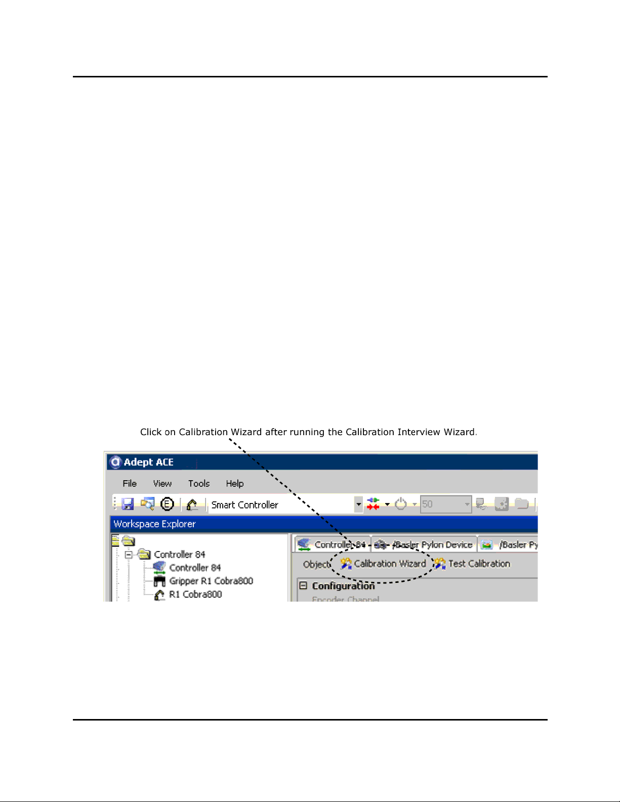
AdeptSight Camera Calibration Wizard - Automated, with Belt
AdeptSight Camera Calibration Wizard - Automated, with Belt
This topic covers calibrating an arm- or fixed-mounted camera to a robot, with a conveyor
belt.
Requirements
l The robot, belt, and camera must be correctly connected and functioning.
l The camera itself must be calibrated. See Standalone Camera Calibration on page
207.
l The AdeptSight Belt Calibration Wizard must have completed successfully.
l The AdeptSight Camera Calibration Interview Wizard must have completed suc-
cessfully.
What this Wizard Does
With this wizard you will:
l Teach the picture-taking position, the vision model, and the placement position
l Perform a robot-to-camera calibration
Procedure
From the AdeptSight Camera Calibration Object window, click Calibration Wizard.
The screen titles will all say "Robot-to-Belt Camera Calibration Sequence".
The screens in this procedure are:
AdeptSight User's Guide, Version 3.2.x, Updated: 8/23/2012
Page 97
Page 98

AdeptSight Camera Calibration Wizard - Automated, with Belt
l Select the End-Effector
l Teach the Vision Tool
The following figures show the model, origin, and bounding box before and after this
procedure has been performed.
Vision Model BeforeTeaching
AdeptSight User's Guide, Version 3.2.x, Updated: 8/23/2012
Page 98
Page 99

AdeptSight Camera Calibration Wizard - Automated, with Belt
Vision ModelAfter Teaching
1. Place the target near the center of the work area.
2. Click Run to take an image.
3. Adjust the model bounding box to fully enclose the model.
Make it close to the perimeter of the model, as shown in the previous figure.
4. Move the origin marker to the center of the model.
l Drag the origin marker to the center of the model with the mouse
or
l Click Edit, to open the Edit window (shown in the following figure).
o
Click Center to center the marker on the bounding box
or
o
Click on the outline of the model, then click Center to center the
marker on the found part
AdeptSight User's Guide, Version 3.2.x, Updated: 8/23/2012
Page 99
Page 100

AdeptSight Camera Calibration Wizard - Automated, with Belt
Edit Window
AdeptSight User's Guide, Version 3.2.x, Updated: 8/23/2012
Page 100
 Loading...