

Page 1

PB-1
This section provides information related to servicing, maintaining, and adjusting post boxes and
cuspidors. Details on how to troubleshoot specific problems relating to post boxes and cuspidors
are presented. For more information on service parts, see the Genuine A-dec Service Parts Catalog,
P/N 85.5000.00 or contact customer service.
85.0812.00, 2003
Post Boxes and Cuspidors Overview
Page 2
85.0812.00, 2003 PB-2
Post Boxes and Cuspidors Post Boxes
S
I
D
E
A
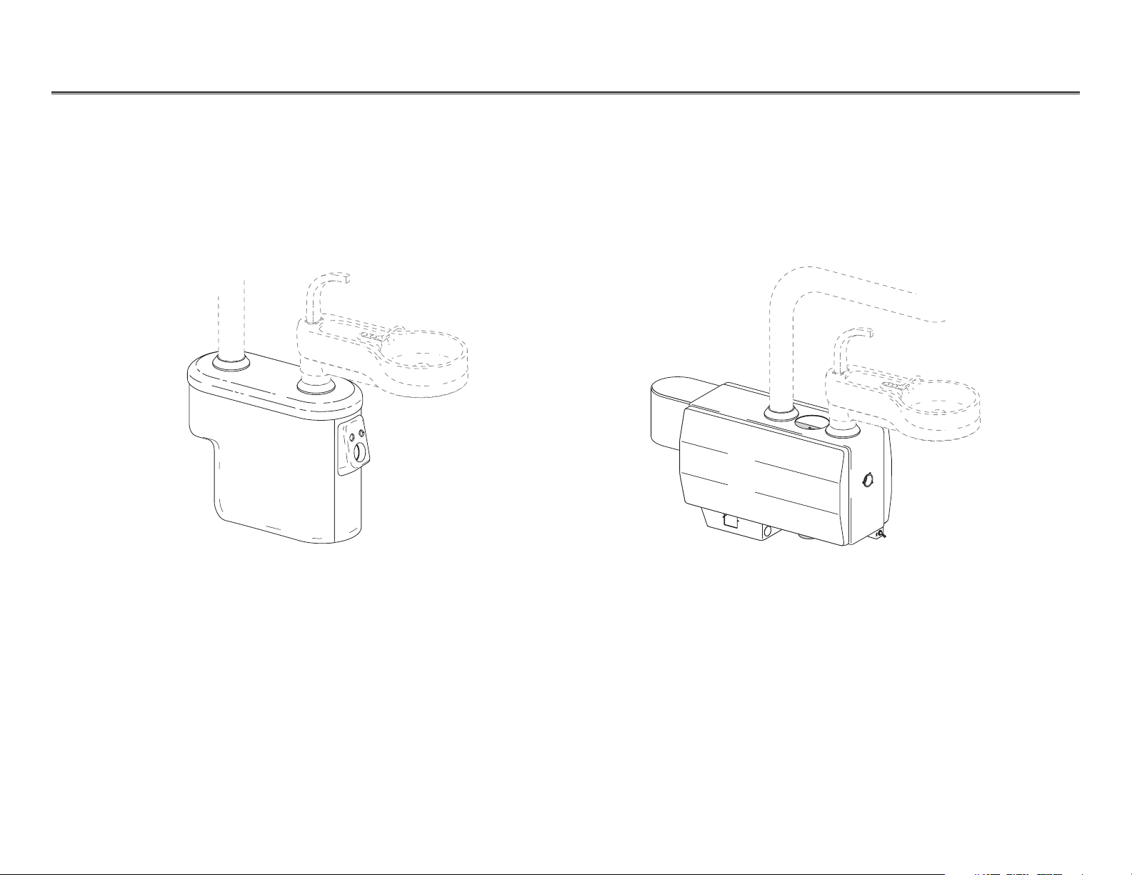
Cascade Post Box
Cascade International Post Box
Identifying Post Boxes
The following pages provide instructions, descriptions, part numbers, and flow diagrams that will
assist you while servicing and troubleshooting post box assemblies. Information for both Cascade
domestic and Cascade international post boxes are shown.
Page 3
85.0812.00, 2003 PB-3
Post Boxes and Cuspidors Post Boxes
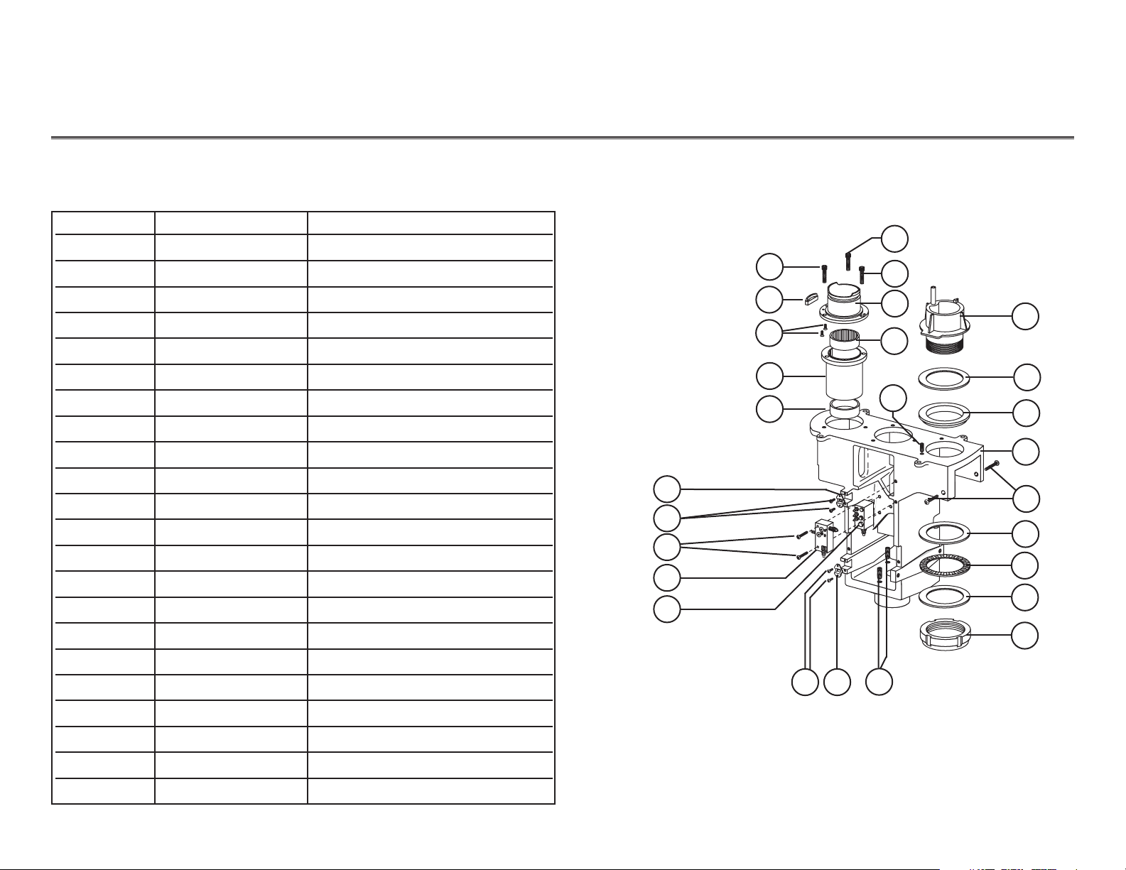
Inside Cascade Post Box
1
2
7
6
14
15
15
11
1
3
4
12
16
17
15
8
7
9
10
6
5
21
19
20
18
1
13
Cascade Post Box
Item # Part Number Description
1 001.009.00 Screw, socket head
2 75.0127.00 Stop
3 001.122.01 Screw, flat head socket
4 75.0125.00 Bearing carrier
5 016.100.00 Bearing sleeve
6 005.012.03 Screw, button head
6 042.221.00 Ball spring
7 002.118.00 Screw, button head
8 005.124.00 Screw, button head
9 75.0113.00 Water manifold assembly
10 75.0138.00 Air manifold assembly, w/o QDs
11 75.0126.00 Mounting hub
12 016.101.00 Roller bearing
13 007.023.00 Setscrew, 1/4-20
14 12.0931.00 Pivot hub
15 016.108.00 Thrust bearing, race
16 12.0911.00 Bushing
17 75.0139.00 Frame
18 005.010.01 Screw, button head
19 016.044.00 Thrust bearing, needle
20 61.0954.00 Lock nut
21 007.059.00 Setscrew, 3/8-16
Page 4
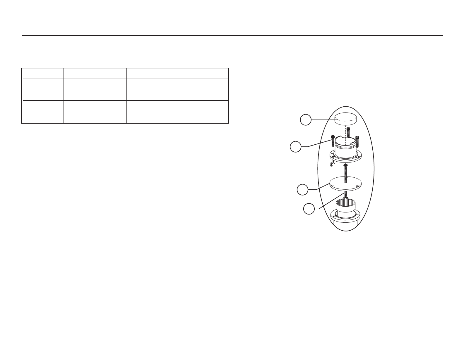
Item # Part Number Description
1 75.0089.00 Trim ring
2 006.002.00 Hex nut
3 75.0128.00 Spacer, bearing hub
4 75.0129.01 Rod
85.0812.00, 2003 PB-4
Post Boxes and Cuspidors Post Boxes
1
2
3
4
Inside Cascade Post Box
Cascade Post Box
Page 5
85.0812.00, 2003 PB-5
Post Boxes and Cuspidors Post Boxes
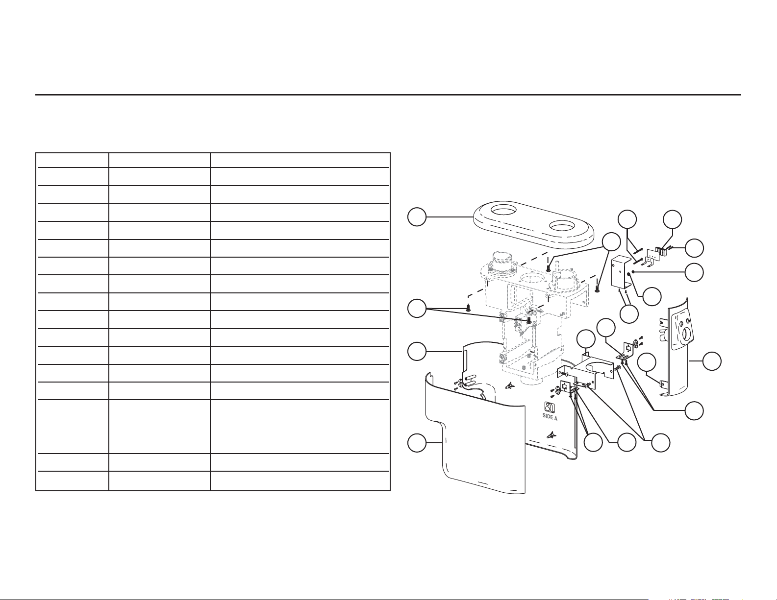
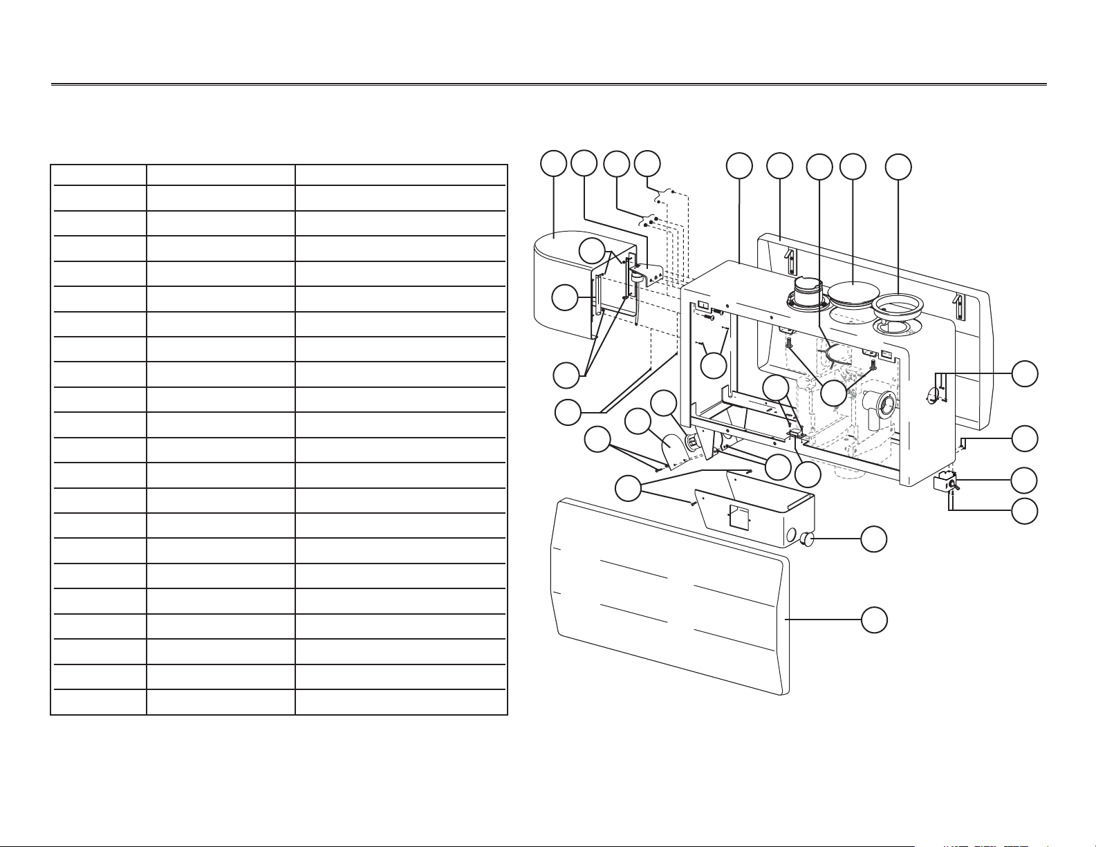
Outside Cascade Post Box
2
5
7
Item # Part Number Description
1 75.0068.00 Top cover
2 005.012.03 Screw, button head
3 75.0069.00 Side cover A
4 75.0070.00 Side cover B
5 005.110.00 Screw, button head
6 041.631.00 Terminal strip
7 001.021.00 Screw, socket head
8 006.002.00 Hex nut
9 004.076.00 Lock washer
10 002.097.00 Screw, button head socket, special
11 75.0110.00 Side front bracket
12 75.0102.00 Umbilical bracket
13 75.0117.00 Nut plate
14 75.0071.00 Vacuum housing w/vacuum
47.1938.00 Vacuum housing Int’l, w/o vacuum
12.0165.00 Vacuum housing assembly
12.0163.00 Vacuum housing w/o vacuum
15 002.015.00 Screw, pan head, phillips
16 005.012.03 Screw, button head
2
1
11
14
15
3
16
11
6
8
9
10
12
4
15
13
Cascade Post Box
Page 6
Item # Part Number Description
1 41.1112.00 Water bottle housing assy
2 47.1237.00 Cap
3 018.035.02 Hole plug, 1/4"
4 028.013.02 Hole plug, 5/32"
5 41.1200.00 Utility box weldment
6 41.0364.01 Side cover assembly
7 47.1349.00 Hole plug clamp
8 47.1348.00 Hole plug, 3-1/2"
9 41.1111.00 Trim ring
10 006.015.00 Hex nut
11 41.1114.00 Mounting bracket
12 028.013.02 Hole plug, 5/32"
13 005.138.00 Screw, button head socket
14 41.1436.00 Umbilical bracket hole cover
15 018.062.02 Hole plug, 1-3/8"
16 001.103.00 Screw, button head socket
17 002.097.00 Screw, button head, special
18 005.012.03 Screw, button head socket
19 006.016.00 Hex nuts, Kep
21 47.1347.00 Master toggle bracket
22 018.010.02 Hole plug, 1-1/4"
85.0812.00, 2003 PB-6
Post Boxes and Cuspidors Post Boxes
Outside Cascade International Post Box
Cascade International Post Box
11
10
2
4
3
10
12
16
15
14
13
19
16
22
5 6
8
97
18
17
20
6
16
19
16
21
1
Page 7
85.0812.00, 2003 PB-7
Post Boxes and Cuspidors Post Boxes
Item # Part Number Description
1 75.0127.00 Stop
2 002.147.00 Screw, socket head
3 001.122.01 Screw, flat head socket
4 006.002.00 Hex nut
5 016.101.00 Roller bearing
6 75.0125.00 Carrier bearing
7 016.100.00 Sleeve bearing
8 75.0126.00 Mounting hub
9 75.0129.01 Rod
Cascade International Post Box
Inside Cascade International Post Box
9
4
10
2
5
6
1
2
3
8
7
Page 8
85.0812.00, 2003 PB-8
Post Boxes and Cuspidors Post Boxes
Item # Part Number Description
1 75.0139.00 Post box frame, master
2 47.1234.00 Electrical assembly
3 005.012.03 Screw, button head
4 004.076.00 Lock washer
5 12.0931.00 Pivot hub
6 016.108.00 Race, thrust bearing
7 007.023.00 Setscrew, 1/4-20 X 3/4
8 75.0113.00 Water manifold assembly
9 005.124.00 Screw, button head socket
10 75.0138.00 Air manifold assembly, w/o QDs
11 007.029.00 Setscrew, 3/8-16 X 1
12 12.0911.00 Cuspidor pivot bushing
13 005.110.00 Screw, button head, socket
14 007.017.00 Setscrew, 1/4-20 X 1/4
15 016.044.00 Needle, thrust bearing
16 61.0954.00 Lock nut
Cascade International Post Box
Inside Cascade International Post Box
5
11
10
15
17
6
1314
16
9
8
11
4
3
2
3
7
12
14
13
Page 9
85.0812.00, 2003 PB-9
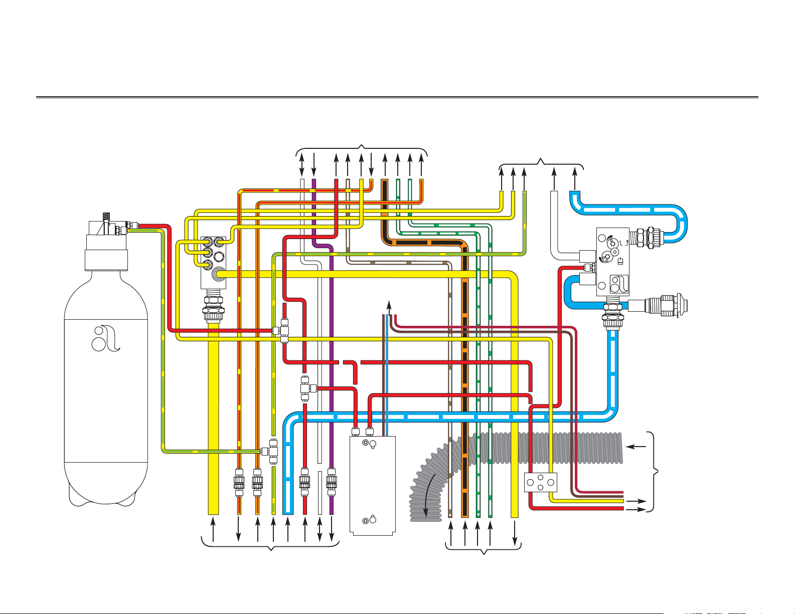
Post Boxes and Cuspidors Post Box Air and Water Flow Diagram
Floor box
Foot control
Assistant’s
instrumentation
Cuspidor
Low voltage
water heater
(optional)
Optional heated
syringe tubing
wiring
To post box
terminal strip
Self-contained water
Air
manifold
Water
manifold
To vacuum
supply
Handpiece controls
Page 10

85.0812.00, 2003 PB-10
Post Boxes and Cuspidors Post Box Electrical Flow Diagram
Wire Color Voltage
Black or Brown 0
Blue or Grey 24
Red 6
Terminal
strip
To heated syringe
tubing (optional)
To low voltage
water heater
(optional)
To floor box
To control head
To light
Terminal Strip Wiring Voltage
Page 11

Item # Part Number Description
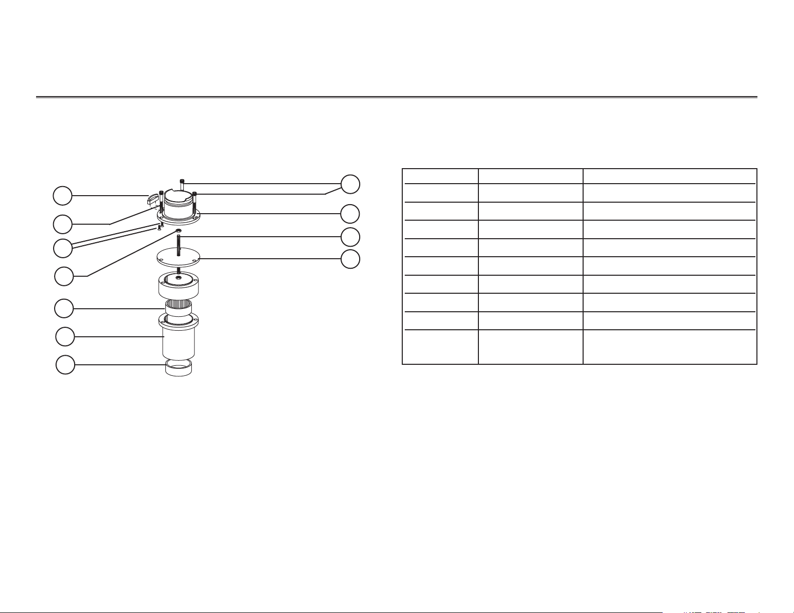
1 022.065.00 Adapter
2 022.014.01 Nut with sleeve
3 004.005.01 Washer
4 023.001.03 Barb, 1/4" pkg 10
5 023.004.03 Barb, 1/8" pkg 10
6 030.009.02 O-ring pkg 10
7 75.0108.00 Stem, fine flow adjustment
8 002.105.00 Screw, button head socket
9 75.0115.00 Stem, flow adjustment
85.0812.00, 2003 PB-11
Post Boxes and Cuspidors Manifold Assemblies
75.0113.00 Water Manifold Assembly
7
2
Water Manifold Assembly
6
8
9
6
1
3
4
3
4
1
2
5
3
Page 12

85.0812.00, 2003 PB-12
Post Boxes and Cuspidors Manifold Assemblies
75.0138.00 Air Manifold Assembly
Air Manifold Assembly
NOTE:Replace the air manifold as a complete assembly.
Page 13

85.0812.00, 2003 PB-13
Post Boxes and Cuspidors Valves
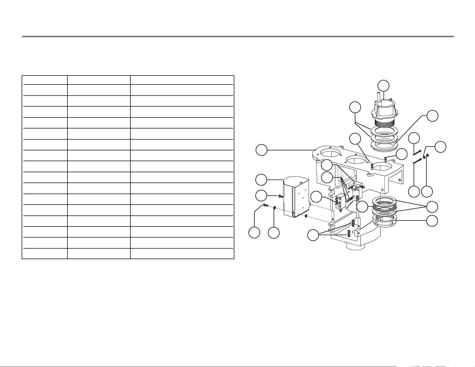
Vacuum Drain Valve
Item # Part Number Description
1 030.004.02 O-ring pkg 10
2 40.1082.00 Diaphragm, sensor
3 40.1086.00 Sensor stem with o-rings
4 030.003.02 O-ring pkg 10
5 030.001.02 O-ring pkg 10
6 40.1081.00 Diaphragm, vacuum
7 023.084.00 Male QD barb, with o-ring, 1/8"
Vacuum Drain Valve
6
3
7
4
5
2
1
4
From cuspidor
To vacuum drain
Vacuum Drain Valve
Vacuum drain valve
Page 14

85.0812.00, 2003 PB-14
Post Boxes and Cuspidors Valves
Vacuum Drain Manual Flush Toggle Valve Assembly
Item # Part Number Description
1 33.0037.01 Toggle and pin kit
2 030.001.02 O-ring pkg 10
3 29.0830.00 Stem with o-rings, 2-way
4 33.0007.00 Disk, brass
5 013.055.00 Spring
Manual Flush Toggle Valve
3
5
2
1
1
From cuspidor
To vacuum drain
Vacuum Drain Manual Flush Toggle Valve Flow
Manual flush toggle
valve (vacuum drain)
2
4
Page 15

85.0812.00, 2003 PB-15
Post Boxes and Cuspidors Cuspidors
Cascade (Phenolic) Cuspidor
Cascade 7284 and Radius 7285
(Vitreous china) Cuspidor
Identifying Cuspidors
The following pages provide instructions, descriptions, part numbers, and flow diagrams that will
assist you while servicing and troubleshooting cuspidor assemblies. Information for both Cascade
and Cascade Radius cuspidors are shown.
Page 16

85.0812.00, 2003 PB-16
Post Boxes and Cuspidors Cuspidors
Cascade Cuspidor
Item # Part number Description
1 75.0039.00 Contoured spout
2 12.0908.01 Button with actuator pkg 2
3 75.0035.01 Screen
4 030.011.02 O-ring
5 12.0913.00 Timed bowl rinse valve
6 001.016.01 Screw, button head socket
7 12.0915.00 N.O. momentary switch assembly
8 12.1144.00 Baseplate
9 024.152.01 Convoluted tubing, Surf 4, 10'
10 40.0783.00 Y-adapter
11 12.0914.00 Tubing clip
12 33.0138.00 3-way micro-valve, cup-fill assembly
(replace as a complete assembly)
13 12.0954.01 Lo-flo needle valve
14 001.016.01 Screw, socket head
15 12.1054.02 Mount screw assembly
16 33.0134.00 2-way micro-valve, cup-fill assembly
(replace as a complete assembly)
17 75.0052.00 Drain tube
18 12.1024.00 Seal
19 006.133.01 Expansion mounting nut pkg 4
3
1
4
6
7
8
9
10
2
14
14
17
16
13
12
14
11
15
15
5
6
Cascade Cuspidor
(Phenolic) Before serial number A650244
18
19
19
Page 17

85.0812.00, 2003 PB-17
Post Boxes and Cuspidors Cuspidors
Cascade 7284 and Radius 7285 Cuspidor
Item # Part Number Description
1 75.0039.00 Contoured spout
2 75.0145.01 Gasket pkg 5
3 030.011.02 O-ring
4 12.1040.00 Socket
5 004.005.02 Washer
6 023.004.03 Barb, 1/8" pkg 10
7 004.203.00 Washer, BUNA-N
8 004.126.00 Washer, nylon
9 006.134.00 Hex nut
10 12.0913.00 Air timed bowl relay assembly
11 12.1042.00 Bracket
12 001.016.01 Screw, socket head
13 12.0915.00 N.O. momentary switch assembly
14 12.1144.00 Baseplate
15 024.152.01 Convoluted tubing
16 75.0060.00 Trim ring
17 75.0091.00 Button
18 12.1079.00 Valve actuator
19 12.1080.00 Valve retainer
20 12.1054.02 Mounting screw
1
7
9
10
13
15
17
8
Cascade Cuspidor
(Vitreous China) Starting with/after serial number A650244
18
19
2
4
3
5
6
14
16
11
20
12
Page 18

85.0812.00, 2003
PB-18
Post Boxes and Cuspidors Cuspidors
Cascade 7284 and Radius 7285 Cuspidor
Item # Part Number Description
1 017.019.00 Bumper
2 006.133.01 Expansion nut
3 001.056.00 Screw, pan head phillips
4 006.009.00 Hex nut
5 004.140.00 Washer
6 004.068.00 Washer
7 33.0138.00 3-way micro-valve, cup-fill valve assy
8011.082.00 Clip pin
9 90.0456.00 Cascade cup timer stabilization kit
10 001.016.01 Screw, socket head
11 12.0914.00 Tubing clip
12 12.0934.00 Cup fill relay assembly
13 12.0953.00 Mini, air pilot valve assembly
14 33.0160.00 3-way restricted diaphragm valve
15 12.1031.00 Bowl spout
16 030.014.02 O-ring
17 75.0035.01 Screen pkg
18 12.1035.00 Cuspidor bowl housing (starting w/
serial number A650244)
19 12.1024.00 Seal
20 75.0052.00 Drain tube
21 12.1054.02 Mount screw assembly
15
10
21
20
13
4
Cascade Cuspidor
(Vitreous China) Starting with/after serial number A650244
16
17
18
2
7
3
8
9
12
14
10
4
11
2
1
19
6
5
4
10
1
Page 19

85.0812.00, 2003 PB-19
Post Boxes and Cuspidors Cup Fill Stabilization Kit
Cup Fill Stabilization Kit
(After January 2000)
90.0456.00 Cup Fill Stabilization Kit
Item # Part Number Description
1 90.0456.00 Cup timer stabilization kit
12.0953.00 (replace on phenolic cuspidor and
12.0954.01 on vitreous china cuspidor)
1
Note:Part number 13.0402.01 is a sub-assembly contained in the
90.0456.00 cup fill stabilization kit. Other part numbers included
in the stabilization kit are not shown.
Do not shorten
tubing
1
Page 20

85.0812.00, 2003
PB-20
Post Boxes and Cuspidors Cuspidor Valves
3-Way Restricted Diaphragm Valve
Location of 3-Way Restricted Diaphragm Valve
Item # Part number Description
1 33.0160.00 3-way restricted diaphragm valve
2 030.010.02 O-ring pkg 10
3 33.0138.00 3-way micro-valve
4 22.0440.02 Diaphragm pkg 10
5 023.036.00 Restrictor barb
33.0160.00 3-Way Restricted Diaphragm Valve
3
2
4
5
1
Page 21

85.0812.00, 2003 PB-21
Post Boxes and Cuspidors Cuspidor Valves
Pilot Air Mini-Valve
Location of Pilot Air Mini-Valve
Item # Part number Description
1 12.0953.00 Pilot air mini-valve (vitreous china)
12.0954.01 Pilot air mini-valve (phenolic)
1
Page 22

85.0812.00, 2003 PB-22
Post Boxes and Cuspidors Cuspidor Valves
Timed Bowl Rinse Relay Valve
Location of Timed Bowl Rinse Relay Valve
Item # Part Number Description
1 12.0913.00 Timed bowl rinse relay valve
2 12.0920.00 Needle valve assembly
3 22.0440.02 Diaphragm pkg 10
4 24.0132.00 Delrin piston with o-ring
5 013.032.00 Spring
6 24.0137.01 Nine-hole gasket pkg 10
1
12.0913.00 Timed Bowl Rinse Relay Valve
2
3
4
5
6
Page 23

85.0812.00, 2003
PB-23
Post Boxes and Cuspidors Cuspidor Valves
Cup Fill Water Relay Valve
Location Of Cup Fill Relay Valve
Item # Part Number Description
1 12.0934.00 Cup fill water relay valve assy
2 013.032.00 Spring
3 24.0137.01 Nine-hole gasket pkg 10
4 24.0440.02 Diaphragm pkg 10
5 24.0132.00 Delrin piston with o-ring
12.0934.00 Cup Fill Relay Valve
4
5
2
1
3
Page 24

85.0812.00, 2003 PB-24
Post Boxes and Cuspidors Manual Cuspidor Flow Diagram
Timed bowl rinse
relay valve
Timed bowl
rinse relay
valve
Cup fill water
relay valve
NOTE:Before January 1996,
this tubing was Surf 4.
To cuspidor cup
fill spout socket
To cuspidor
bowl spout
From post box
Item # Part Number Description
1 33.0134.00 2-way bowl rinse valve
2 33.0138.00 3-way bowl rinse valve
1
2
Page 25

85.0812.00, 2003 PB-25
Post Boxes and Cuspidors Automatic Cuspidor Flow Diagram
Timed bowl rinse
relay valve
To cuspidor
cup fill socket
From post box
To cuspidor
bowl spout
Cup fill air
relay valve
Cup fill water
relay valve
NOTE:Before January 1996,
this tubing was Surf 4.
Item # Part Number Description
1 33.0134.00 2-way bowl rinse valve
2 33.0138.00 3-way bowl rinse valve
3 023.036.00 1/8" restrictor barb
1
2
From timed bowl
rinse relay valve
3
Pilot air
mini-valve
Cup timer stabilization kit (adjustable needle valve is
replaced by the cup timer stabilization kit).
NOTE: Do not shorten tubing.
NOTE: Do not shorten tubing.
Page 26

85.0812.00, 2003 PB-26
Post Boxes and Cuspidors Adjustments
Adjusting
the Vacuum
Drain Valve
The vacuum drain valve has been pre-set at the factory.
Varying water or vacuum conditions may require further
adjustment if vacuum drain valve does not turn off or water
backs up into the cuspidor bowl.
To adjust the drain valve:
Task Description
1 Use a standard screwdriver to turn the water sensing
adjustment screw clockwise until you hear the actuator
beginning to open.
NOTE: When the valve is open, the diaphragm in it may
vibrate, causing a high pitch noise.
2Turn the adjustment screw counterclockwise until you hear
the vacuum drain valve close; then turn the screw 1/8"
counterclockwise.
3Test for correct function by rinsing the cuspidor. If water
backs up into the cuspidor bowl
•Turn the adjustment screw slightly clockwise to
decrease the amount of water required to open the
valve, or
•Turn the adjustment screw counterclockwise to
increase the amount of water required to open
the valve.
Vacuum Drain Assembly
Item # Description
1Water sensor body
2Vacuum drain valve
3Water sensor adjustment screw
1
3
2
Page 27

85.0812.00, 2003 PB-27
Post Boxes and Cuspidors Adjustments
Adjusting the
Bowl Rinse and
Cup Fill Flow
Adjustment Screw Locations
To... Do this...
Increase bowl rinse time Adjust screw clockwise (tighten)
Decrease bowl rinse time Adjust screw counterclockwise (loosen)
Increase cup fill or bowl rinse flow Adjust screw clockwise
Increase cup fill or bowl rinse flow Adjust screw counterclockwise
The bowl rinse time can be adjusted by turning the timed bowl rinse relay adjustment screw (accessed
from the underside of the cuspidor housing).
The cup fill and bowl rinse flow can be adjusted by turning the adjustment screw, found on the water
manifold, inside the post box.
Timed Bowl Rinse
Relay Valve
Water Manifold
Bowl rinse flow
adjustment screw
(Flow indicator
markings)
Cup fill flow
adjustment
screw
Bowl rinse timing
adjustment screw
NOTE: The placement of the dot on the adjustment screw and the flow
indicator marking show where adjustments are set.
(Flow indicator
marking)
Page 28

85.0812.00, 2003 PB-28
Post Boxes and Cuspidors Troubleshooting
Problem
Action
Burst of water from cup fill or
bowl rinse when first used
Inconsistent cup fill function
Air leak around the lo-flo
needle valve
Moisture in air lines or valves
Bowl rinse timing is incorrect,
too short or too long
Check water pressure from floor box. If below 30 psi
• adjust water pre-regulator to 30-40 psi, and
•retest cup fill or bowl rinse function.
Check for cup fill stabilization kit installation. If the kit is not installed, install it (P/N 90.0456.00)
If air leaks around the lo-flo needle valve
• tighten any loose connections
•replace defective parts, and
• test cup fill function.
If moisture is present in the air lines or valves
•dry out or replace all tubings or valves
• determine source of moisture and replace defective parts, and
• test cup fill function.
Adjust the bowl rinse timing. After locating the timing adjustment (under the cuspidor bowl housing)
• increase the bowl rinse by turning the adjustment screw clockwise, or
•decrease the bowl rinse by turning the adjustment screw counterclockwise.
Troubleshooting Cup
Fill, Bowl Rinse, and
Valve Controls
Tips and troubleshooting information are listed to assist in distinguishing cuspidor and valve
control problems.
 Loading...