

Page 1
User’s Manual
9640A
Enhanced Scan T ool
Professional
Page 2

Scan Tool Information
Complete the following list using the
function “Tool Information” on
page 3-4. Provide this information
when contacting customer support.
Serial No:
SW ID:
HW Ver:
Boot Ver:
Prod ID:
Board ID:
Burn Date:
Burn Loc:
Copyr igh t In fo rm a tio n
Copyright © 2003 Actron Manufacturing, Inc.
All rights reserved.
The information, specifications and illustrations in this
manual are b ased o n the latest i nf orma tion ava i lable at the
time of printing.
to make changes at any time without notice.
Actron Manufacturing
reserves the right
Page 3

Safety
!
Table of Contents
Section 1 –––––––––– Using this Manual
Section 2 –––––––––––– Getting Started
Section 3 ––––––––Using The Scan Tool
Section 4 ––– Global OBD II Diagnostics
Section 5 –––––––––––– GM Diagnostics
Section 6 –––––––––––Ford Diagnostics
ToC
1
2
3
4
5
6
Section 7 ––––––––Chrysler Diagnostics
Section 8 ––––– Help & Troubleshooting
Appendix A ––––– Data Link Connectors
Appendix B –––––––––––––––– Glossary
7
8
A
B
Page 4

Page 5
Safety Precautions
For your safety , read this manual thoroughly before oper ating your Professional
Enhanced Scan Tool. Always r efer to and foll ow safety messag es and test procedures provided by the manufacturer of the vehi cle or equipment being tested .
Y our scan t ool is intend ed for us e by properl y trained, sk illed pr ofessiona l automotive techni cians. The safety mes sages presented b elow and throughou t this
user’s manual are reminders to the operator to exercise extreme care when
using this test instrument.
Read All Instructions
Read, understa nd and fol low al l safet y mes sages and i nstru ctions in thi s manual and on the test equipment. Safety messag es in this secti on of the manual
contain a signal word with a three-part message and, in some instances, an
icon. The signal word indicates the level of the hazard in a situation.
Safety Messages
Safety messages are provided t o help prevent personal injury and equipment
damage. All safety messages are introduced by a signal word indicating the
hazard level. The types of safety messages are:
DANGER
!
WARNING
!
Indicates an imminently hazardous situation which, if not
avoided, will r esult in deat h or serious i njury to the o perator
or to bystanders.
Indicates a potential ly hazardous situation which, if not
avoided, could resul t in deat h or serio us injur y to the operator or to bystanders.
!
Indicates a potential ly hazardous situation which, if not
!
CAUTION
IMPORTANT
Safety messages contain three different type styles.
• Normal type states the hazard.
• Bold type states how to avoid the hazard.
•
Italic
An icon, when present, gives a graphical description of the potential hazard.
Example
• • • • • • • • • • • • • • • • • • • • • • • • • • • • • • • • • • • • • • • • • • • • • • • • • • • • • • Safety – i
avoided, may resul t in mod erate or m inor inj ury to the operator or to bystanders.
Indicates a situation which, if not avoided, may result in
damage to the test equipment or vehi cle.
type states th e possible consequences of not avoidi ng the hazard.
:
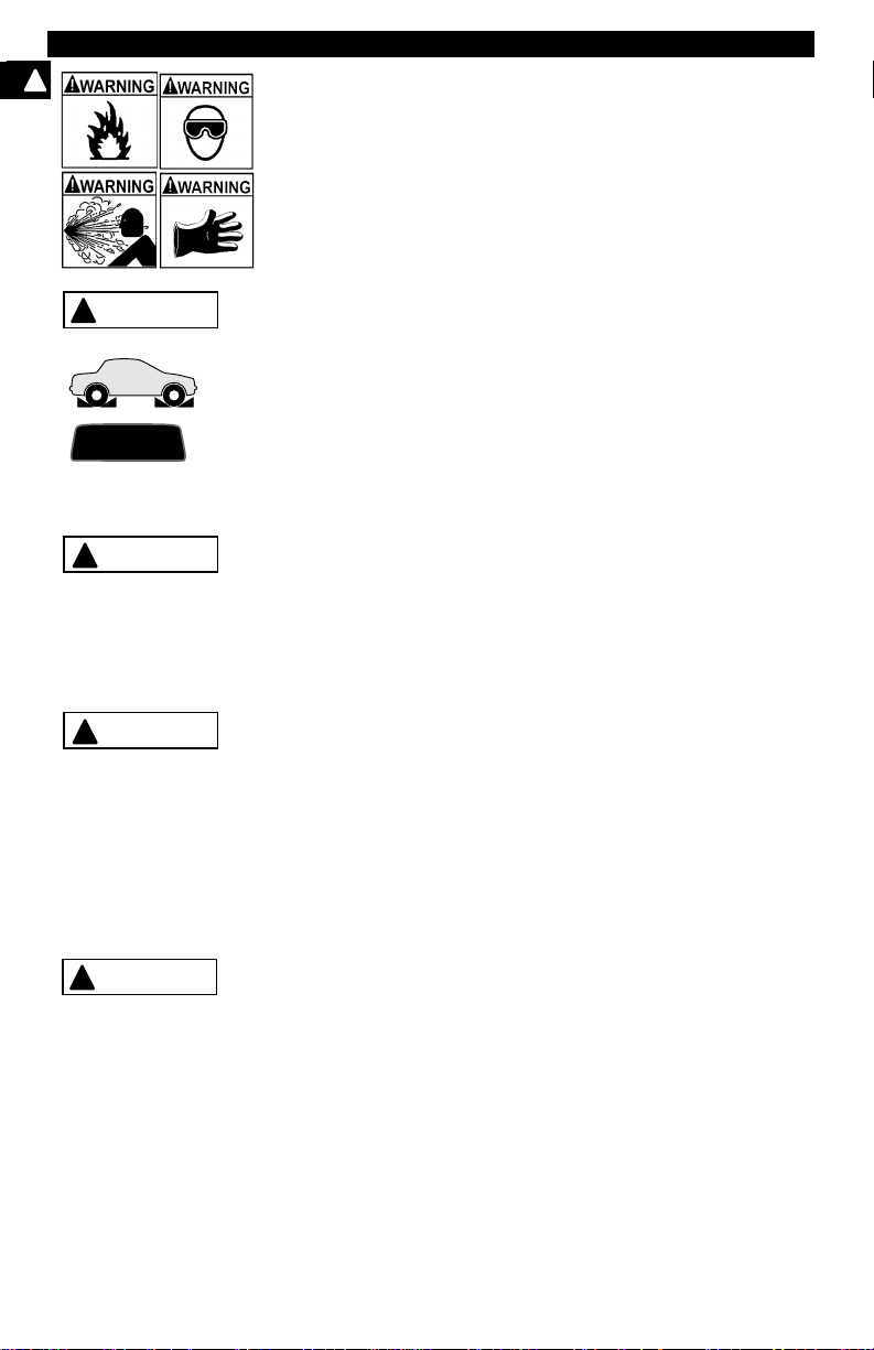
Engine systems can malfunction expelling fuel, oil vapors, hot
steam, hot toxic exhaust gases, acid, refrigerant and other
debris.
Wear safety goggles and protective gloves, user and
bystander . Ever yday eyeglasses onl y have impact resistant
lenses, they are NOT safety glasses.
Engine systems that malfunction can cause injury.
Page 6
Safety Precautions
!
Important Safe ty Instru ct ion s
Risk of electric shoc k.
• Do not exceed volt age limits between inputs as indicated
in the “Specifi cations” on page 3-2.
• Use extre me caution when worki ng with circuit s that have
greater than 60 volts DC or 24 volts AC.
Electric shock can cause injury .
Risk of explosion.
• Wear safety goggles and protective clothing, user and
bystan der. Everyday eyeglasses only have impact resistant lenses, they are NOT safety glasses.
• Do not use this system in environments where explosive
vapor may collect, such as i n below-ground pits , confined
areas, or area s that are less than 18 inches above t he floor .
• Use this equipment in locations with mechanical ventilation providing at least four air changes per hour.
• Flammable fuel and vapors can ignite.
• Do not smoke, stri ke a match, or cause a spark in the vicinity of the battery. Battery gases can ignite.
• Avoid making accidental connection between battery terminals. Do not place uninsula ted m etal tools on the battery.
• When removing battery cabl es, remove ground cable firs t.
• Avoid sparks when connecting or disconnecting power
leads to battery.
• Be sure ignition is OFF, headlight s and other accessori es
are OFF and vehicle doors are closed before disconnecting battery cables. Thi s also helps prevent damage to
on-board computer systems.
• Always disconnect batt ery ground connections before
servicing electrical system components.
Explosion can cause injury.
WAR NI NG
!
Risk of poisoning.
• Use this equipment in locations with mechanical ventilation providing at least four air changes per hour. Engine
exhaust contains odorless lethal gas.
• Route exhaust outside while testing with engine running.
Poisoning can result in death or serious injury.
!
WARNING
Battery acid is a highl y corrosive sulfuric acid.
• Wear safety goggles and protective gloves, user and
bystan der. Everyday eyeglasses only have impact resistant lenses, they are NOT safety glasses.
• Make sure someone can hear you or is close enough to
provide aid when working near a battery.
• Have plenty of fresh wat er and soap nearby . If battery aci d
contacts skin, clothing, or eyes, flush exposed area with
soap and water for 10 minutes.
• Seek medical help.
• Do not touch eyes while working near battery.
Battery acid can burn eyes and skin.
Risk of fire.
• Wear safety goggles and protective clothing, user and
bystan der. Everyday eyeglasses only have impact resistant lenses, they are NOT safety glasses.
Safety – ii • • • • • • • • • • • • • • • • • • • • • • • • • • • • • • • • • • • • • • • • • • • • • • • • • • • • •
Page 7
Safety Precautions
• Do not position head directly over or in front of throttle
body. Do not pour gasoline down throttle body when
cranking or ru nning engi ne, when wor king wit h fuel delivery systems or any open fuel line. Engine backfire can
occur when air cleaner is out of positi on.
• Do not use fuel injector cleaning solvents when performing diagnostic testi ng.
• Keep cigarett es, sp a rks, op en f lame and o ther sources of
ignition away from vehicl e.
• Keep a dry chemical (Class B) fire extinguisher rated for
gasoline, chemical and electrical fires in work area.
Fire can cause death or serious injury .
Risk of flying particles.
Wear safety goggl es while using elect rical equipment . Electrical equipment or rotating engine parts can cause flying
particles.
Flying particles can cause eye injury.
Risk of burns.
Batteries can produce a short-circuit current high enough
to weld je w e lr y to me tal . Re move jew e lr y su ch a s ri n g s,
bracelets and watches before working near batteri es.
Short circuits can cause injury.
WARNING
!
Risk of burns.
• Do not remove radiator cap unless engine is cold. Pressurized engine cool ant may be hot.
• Do not touch hot exhaust systems, ma nifolds, engines,
radiators, sampl e probe, etc.
• Wear insulated gloves when handling hot engine components.
• Tester leads can become hot after extended testing in
close proximity to manifolds etc.
Hot components can cause injury.
Risk of expelling fue l, oil vapors, hot steam, hot toxic exhaus t
gases, acid, refri gerant and other debris.
• Wear safety goggles and protective clothing, user and
bystan der. Everyday eyeglasses only have impact resistant lenses, they are NOT safety glasses.
• Engine systems can malfunction expelling fuel, oil
vapors, hot st eam, hot toxi c exhaust gas es, aci d, ref rigerant and other debris.
Fuel, oil vapors, hot steam, hot toxic exhaust gases, acid,
refrigerant and other debris can cause serious injury.
The engine compartment contains electrical connections and
hot or moving parts.
• Keep yourself, test le ads, clothing and other obj ect s clear
of electrical connections and hot or moving engine parts.
• Do not wear watches, rings, or loo se fitting cl othing when
working in an engine compartment.
• Do not place test equipment or tools on fenders or other
places in the engine compartment.
• Barriers are recommended to help identify dan ger zones
in test area.
• Prevent personnel f rom walking through immediate test
area.
Contact with electrical connections and hot or moving parts
can cause injury.
• • • • • • • • • • • • • • • • • • • • • • • • • • • • • • • • • • • • • • • • • • • • • • • • • • • • • Safety – iii
!
Page 8
Safety Precautions
!
WARNING
!
PR N DL 2
!
CAUTION
!
CAUTION
DANGER
!
Risk of injury.
• This equipment should be oper ated by qualified personnel only.
• Use this equipment onl y as described in this manual. Use
only the manufacturer’s recommended attachments.
• Do not operate equipment with a damaged cord or if the
equipment has been dropped or damaged, until it has
been examined by a qualified service representative.
Operation of this equipment by anyone other than qualified
personnel may result in injury.
Risk of unexpected vehicle movement.
• Block drive wheels before performing a test with engine
running.
• Unless instruct ed otherwise, set parking bra ke and pu t
gear selector in neut ral for standar d transmissions or park
for automatic transmissions.
• If vehicle has an aut omatic p ar king br ake r elease, disconnect release mech anism for testing and reconnect when
testing is completed.
• Do not leave a running engine unattended.
A moving vehicle can cause injury.
Risk of equipment or circ uit damage.
• Unless specific ally directed by the manufacturer, make
sure the ignition i s OFF before connect ing or disconnec ting connectors or any vehi cle electrical terminals.
• Do not create a short between bat tery terminals with a
jumper wire or tools.
Improper equipment use can cause equipment or circuit damage.
Misdiagnosis may lead to incorrect or improper repair and/or
adjustment.
Do not rely on errati c, questionable, or ob viously erroneous
test informati on or result s. If test in formation or re sults ar e
erratic, questionable, or obviously erroneous, make sure
that all connectio ns and da ta e ntr y infor mation are corr ect
and that the test proc edure was perform ed correctly . If test
information or resul ts ar e sti ll su spicious , do not use them
for diagnosis.
Improper repair and/or adjustment may cause vehicle or equipment damage or unsafe operation.
Some vehicles are equi pped wit h air bags. You must follow
vehicle service manual’s warnings when working around the
air bag components or wiring. If the service manual’s instructions are not follo wed, the air bag may open up unexpectedly,
resulting in perso nal injury. Note that the air bag can still open
up several minutes af ter the ignition key is off (or even if the
vehicle battery is disconnected) because of a speci al energy
reserve module.
Safety – iv • • • • • • • • • • • • • • • • • • • • • • • • • • • • • • • • • • • • • • • • • • • • • • • • • • • •
Page 9

Table of Contents
Safety Precautions
Section 1 – Using This Manual
Section 2 – Getting Started
Vehicle Service Information . . . . . . . . . . . . . . . . . . . . . . . . . . . . . . . . . . . . 2-1
Introduction to On-Board Diagnostics . . . . . . . . . . . . . . . . . . . . . . . . . . . 2-1
Diagnostic Link Connectors (DLC) . . . . . . . . . . . . . . . . . . . . . . . . . . . . . . 2-3
OBD II (J1962) . . . . . . . . . . . . . . . . . . . . . . . . . . . . . . . . . . . . . . . . . . . . 2-3
Ford Historic . . . . . . . . . . . . . . . . . . . . . . . . . . . . . . . . . . . . . . . . . . . . . . 2-4
GM Historic . . . . . . . . . . . . . . . . . . . . . . . . . . . . . . . . . . . . . . . . . . . . . . . 2-6
Chrysler Historic . . . . . . . . . . . . . . . . . . . . . . . . . . . . . . . . . . . . . . . . . . . 2-7
Diagnostic Trouble Codes (DTCs) . . . . . . . . . . . . . . . . . . . . . . . . . . . . . . . 2-7
Section 3 – Using The Scan Tool
The Scan Tool . . . . . . . . . . . . . . . . . . . . . . . . . . . . . . . . . . . . . . . . . . . . . . . 3-1
Specifications . . . . . . . . . . . . . . . . . . . . . . . . . . . . . . . . . . . . . . . . . . . . . 3-2
Accessories . . . . . . . . . . . . . . . . . . . . . . . . . . . . . . . . . . . . . . . . . . . . . . 3-2
Display . . . . . . . . . . . . . . . . . . . . . . . . . . . . . . . . . . . . . . . . . . . . . . . . . . 3-2
Keyboard . . . . . . . . . . . . . . . . . . . . . . . . . . . . . . . . . . . . . . . . . . . . . . . . 3-2
Power . . . . . . . . . . . . . . . . . . . . . . . . . . . . . . . . . . . . . . . . . . . . . . . . . . . 3-3
Scan Tool Setup . . . . . . . . . . . . . . . . . . . . . . . . . . . . . . . . . . . . . . . . . . . 3-4
Connecting The Scan Tool . . . . . . . . . . . . . . . . . . . . . . . . . . . . . . . . . . . . . 3-7
Vehicle Selection . . . . . . . . . . . . . . . . . . . . . . . . . . . . . . . . . . . . . . . . . . 3-7
Keep Current Vehicle . . . . . . . . . . . . . . . . . . . . . . . . . . . . . . . . . . . . . . . 3-7
Changing the Vehicle . . . . . . . . . . . . . . . . . . . . . . . . . . . . . . . . . . . . . . . 3-8
User Interface . . . . . . . . . . . . . . . . . . . . . . . . . . . . . . . . . . . . . . . . . . . . . 3-9
User Responses . . . . . . . . . . . . . . . . . . . . . . . . . . . . . . . . . . . . . . . . . . . 3-9
Viewing Data . . . . . . . . . . . . . . . . . . . . . . . . . . . . . . . . . . . . . . . . . . . . . . 3-9
ToC
Page 10

Section 4 – Global OBD II Diagnostics
Manual Info . . . . . . . . . . . . . . . . . . . . . . . . . . . . . . . . . . . . . . . . . . . . . . . . . . 4-1
I/M Readiness . . . . . . . . . . . . . . . . . . . . . . . . . . . . . . . . . . . . . . . . . . . . . . . . 4-1
Read Codes . . . . . . . . . . . . . . . . . . . . . . . . . . . . . . . . . . . . . . . . . . . . . . . . . 4-2
Pending Codes . . . . . . . . . . . . . . . . . . . . . . . . . . . . . . . . . . . . . . . . . . . . . . . 4-3
ToC
Erase Codes . . . . . . . . . . . . . . . . . . . . . . . . . . . . . . . . . . . . . . . . . . . . . . . . . 4-3
View Data . . . . . . . . . . . . . . . . . . . . . . . . . . . . . . . . . . . . . . . . . . . . . . . . . . . 4-4
View Freeze Data . . . . . . . . . . . . . . . . . . . . . . . . . . . . . . . . . . . . . . . . . . . . . 4-5
O2 Monitor Test . . . . . . . . . . . . . . . . . . . . . . . . . . . . . . . . . . . . . . . . . . . . . . 4-6
Non-Continuous Test s . . . . . . . . . . . . . . . . . . . . . . . . . . . . . . . . . . . . . . . . . 4-7
On-Board Systems . . . . . . . . . . . . . . . . . . . . . . . . . . . . . . . . . . . . . . . . . . . . 4-7
Record Data . . . . . . . . . . . . . . . . . . . . . . . . . . . . . . . . . . . . . . . . . . . . . . . . . 4-8
Vehicle Info . . . . . . . . . . . . . . . . . . . . . . . . . . . . . . . . . . . . . . . . . . . . . . . . . . 4-9
Modules Present . . . . . . . . . . . . . . . . . . . . . . . . . . . . . . . . . . . . . . . . . . . . 4-10
Review Data . . . . . . . . . . . . . . . . . . . . . . . . . . . . . . . . . . . . . . . . . . . . . . . . 4-10
Playback . . . . . . . . . . . . . . . . . . . . . . . . . . . . . . . . . . . . . . . . . . . . . . . 4-11
Print Data . . . . . . . . . . . . . . . . . . . . . . . . . . . . . . . . . . . . . . . . . . . . . . . . . . 4-12
Printing Data (except Playback) . . . . . . . . . . . . . . . . . . . . . . . . . . . . . . 4-12
Printing Playback Data . . . . . . . . . . . . . . . . . . . . . . . . . . . . . . . . . . . . . 4-13
Code Lookup . . . . . . . . . . . . . . . . . . . . . . . . . . . . . . . . . . . . . . . . . . . . . . . 4-14
Section 5 – GM Diagnostics
GM Historic (OBD I) Diagnostics . . . . . . . . . . . . . . . . . . . . . . . . . . . . . . . . 5-1
Manual Info . . . . . . . . . . . . . . . . . . . . . . . . . . . . . . . . . . . . . . . . . . . . . . 5-1
Read Codes . . . . . . . . . . . . . . . . . . . . . . . . . . . . . . . . . . . . . . . . . . . . . . 5-1
Erase Codes . . . . . . . . . . . . . . . . . . . . . . . . . . . . . . . . . . . . . . . . . . . . . 5-2
View Data . . . . . . . . . . . . . . . . . . . . . . . . . . . . . . . . . . . . . . . . . . . . . . . . 5-3
Record Data . . . . . . . . . . . . . . . . . . . . . . . . . . . . . . . . . . . . . . . . . . . . . . 5-4
Review Data . . . . . . . . . . . . . . . . . . . . . . . . . . . . . . . . . . . . . . . . . . . . . . 5-5
Field Service . . . . . . . . . . . . . . . . . . . . . . . . . . . . . . . . . . . . . . . . . . . . . 5-6
Code Lookup . . . . . . . . . . . . . . . . . . . . . . . . . . . . . . . . . . . . . . . . . . . . . 5-8
Print Data . . . . . . . . . . . . . . . . . . . . . . . . . . . . . . . . . . . . . . . . . . . . . . . . 5-8
GM Enhan c ed (O BD II) Diagn ostics . . . . . . . . . . . . . . . . . . . . . . . . . . . . . . 5-9
Manual Info . . . . . . . . . . . . . . . . . . . . . . . . . . . . . . . . . . . . . . . . . . . . . . 5-9
I/M Readiness . . . . . . . . . . . . . . . . . . . . . . . . . . . . . . . . . . . . . . . . . . . . 5-9
Read Codes . . . . . . . . . . . . . . . . . . . . . . . . . . . . . . . . . . . . . . . . . . . . . . 5-9
Pending Codes . . . . . . . . . . . . . . . . . . . . . . . . . . . . . . . . . . . . . . . . . . 5-10
Erase Codes . . . . . . . . . . . . . . . . . . . . . . . . . . . . . . . . . . . . . . . . . . . . 5-10
View Data . . . . . . . . . . . . . . . . . . . . . . . . . . . . . . . . . . . . . . . . . . . . . . . 5-10
View Freeze Data . . . . . . . . . . . . . . . . . . . . . . . . . . . . . . . . . . . . . . . . 5-12
O2 Monitor Test . . . . . . . . . . . . . . . . . . . . . . . . . . . . . . . . . . . . . . . . . . 5-12
Non-Continuous Tests . . . . . . . . . . . . . . . . . . . . . . . . . . . . . . . . . . . . . 5-12
On-Board Systems . . . . . . . . . . . . . . . . . . . . . . . . . . . . . . . . . . . . . . . . 5-12
Record Data . . . . . . . . . . . . . . . . . . . . . . . . . . . . . . . . . . . . . . . . . . . . . 5-13
Vehicle Info . . . . . . . . . . . . . . . . . . . . . . . . . . . . . . . . . . . . . . . . . . . . . 5-13
Review Data . . . . . . . . . . . . . . . . . . . . . . . . . . . . . . . . . . . . . . . . . . . . . 5-13
Print Data . . . . . . . . . . . . . . . . . . . . . . . . . . . . . . . . . . . . . . . . . . . . . . . 5-13
Code Lookup . . . . . . . . . . . . . . . . . . . . . . . . . . . . . . . . . . . . . . . . . . . . 5-13
ii
Page 11

Section 6 – Ford Diagnostics
Ford Historic Self-Test Routines . . . . . . . . . . . . . . . . . . . . . . . . . . . . . . . . 6-1
Manual Info . . . . . . . . . . . . . . . . . . . . . . . . . . . . . . . . . . . . . . . . . . . . . .. 6-1
Read KOEO Codes . . . . . . . . . . . . . . . . . . . . . . . . . . . . . . . . . . . . . . . .. 6-1
Read KOER Codes . . . . . . . . . . . . . . . . . . . . . . . . . . . . . . . . . . . . . . . .. 6-3
Review Codes . . . . . . . . . . . . . . . . . . . . . . . . . . . . . . . . . . . . . . . . . . . .. 6-5
Erase Codes . . . . . . . . . . . . . . . . . . . . . . . . . . . . . . . . . . . . . . . . . . . . .. 6-6
Wiggle Test (EEC-IV Vehicles) . . . . . . . . . . . . . . . . . . . . . . . . . . . . . . .. 6-7
Output Switch Test (EEC-IV Vehicles) . . . . . . . . . . . . . . . . . . . . . . . . .. 6-8
Cylinder (Cyl) Balance Test (EEC-IV Vehicles) . . . . . . . . . . . . . . . . . . .. 6-9
IVSC-Speed Ctrl (EEC-IV Vehicles) . . . . . . . . . . . . . . . . . . . . . . . . . .. 6-11
STAR Test Mode (EEC-IV, MECS and MCU Vehicles) . . . . . . . . . . .. 6-12
Code Lookup . . . . . . . . . . . . . . . . . . . . . . . . . . . . . . . . . . . . . . . . . . . .. 6-14
Print Data . . . . . . . . . . . . . . . . . . . . . . . . . . . . . . . . . . . . . . . . . . . . . . .. 6-14
DCL Data Functions (EEC-IV Vehicles) . . . . . . . . . . . . . . . . . . . . . . .. 6-15
Ford Enhanced (OBD II) Diagnostics . . . . . . . . . . . . . . . . . . . . . . . . . . . . 6-18
Manual Info . . . . . . . . . . . . . . . . . . . . . . . . . . . . . . . . . . . . . . . . . . . . .. 6-18
I/M Readiness . . . . . . . . . . . . . . . . . . . . . . . . . . . . . . . . . . . . . . . . . . .. 6-18
Read MIL DTC . . . . . . . . . . . . . . . . . . . . . . . . . . . . . . . . . . . . . . . . . . .. 6-18
Read All DTC . . . . . . . . . . . . . . . . . . . . . . . . . . . . . . . . . . . . . . . . . . . .. 6-19
Pending Codes . . . . . . . . . . . . . . . . . . . . . . . . . . . . . . . . . . . . . . . . . .. 6-19
Erase Codes . . . . . . . . . . . . . . . . . . . . . . . . . . . . . . . . . . . . . . . . . . . .. 6-19
View Data . . . . . . . . . . . . . . . . . . . . . . . . . . . . . . . . . . . . . . . . . . . . . .. 6-19
View Freeze Data . . . . . . . . . . . . . . . . . . . . . . . . . . . . . . . . . . . . . . . .. 6-20
Quick Tests . . . . . . . . . . . . . . . . . . . . . . . . . . . . . . . . . . . . . . . . . . . . .. 6-21
Quick Tests (7.3L Powerstroke Diesel Only) . . . . . . . . . . . . . . . . . . . .. 6-24
O2 Monitor Test . . . . . . . . . . . . . . . . . . . . . . . . . . . . . . . . . . . . . . . . . .. 6-26
Non-Continuous Tests . . . . . . . . . . . . . . . . . . . . . . . . . . . . . . . . . . . . .. 6-26
On-Board Systems . . . . . . . . . . . . . . . . . . . . . . . . . . . . . . . . . . . . . . .. 6-26
Record Data . . . . . . . . . . . . . . . . . . . . . . . . . . . . . . . . . . . . . . . . . . . .. 6-27
Vehicle Info . . . . . . . . . . . . . . . . . . . . . . . . . . . . . . . . . . . . . . . . . . . . .. 6-27
Review Data . . . . . . . . . . . . . . . . . . . . . . . . . . . . . . . . . . . . . . . . . . . .. 6-27
Print Data . . . . . . . . . . . . . . . . . . . . . . . . . . . . . . . . . . . . . . . . . . . . . . .. 6-27
Code Lookup . . . . . . . . . . . . . . . . . . . . . . . . . . . . . . . . . . . . . . . . . . . .. 6-27
ToC
iii
Page 12

Section 7 – Chrysler Diagnostics
Manual Info . . . . . . . . . . . . . . . . . . . . . . . . . . . . . . . . . . . . . . . . . . . . . . . . . . 7-1
Read Codes . . . . . . . . . . . . . . . . . . . . . . . . . . . . . . . . . . . . . . . . . . . . . . . . . 7-1
Read Temporary Codes . . . . . . . . . . . . . . . . . . . . . . . . . . . . . . . . . . . . . . . . 7-2
Erase Codes . . . . . . . . . . . . . . . . . . . . . . . . . . . . . . . . . . . . . . . . . . . . . . . . . 7-3
ToC
View Data . . . . . . . . . . . . . . . . . . . . . . . . . . . . . . . . . . . . . . . . . . . . . . . . . . . 7-4
Record Data . . . . . . . . . . . . . . . . . . . . . . . . . . . . . . . . . . . . . . . . . . . . . . . . . 7-5
Switch Test . . . . . . . . . . . . . . . . . . . . . . . . . . . . . . . . . . . . . . . . . . . . . . . . . . 7-6
Actuator Test . . . . . . . . . . . . . . . . . . . . . . . . . . . . . . . . . . . . . . . . . . . . . . . . 7-7
Idle Speed Test . . . . . . . . . . . . . . . . . . . . . . . . . . . . . . . . . . . . . . . . . . . . . . . 7-8
Sensor Test . . . . . . . . . . . . . . . . . . . . . . . . . . . . . . . . . . . . . . . . . . . . . . . . . . 7-8
Controller Info . . . . . . . . . . . . . . . . . . . . . . . . . . . . . . . . . . . . . . . . . . . . . . . 7-9
Reset EMR Lamp . . . . . . . . . . . . . . . . . . . . . . . . . . . . . . . . . . . . . . . . . . . . . 7-9
Set Basic Time . . . . . . . . . . . . . . . . . . . . . . . . . . . . . . . . . . . . . . . . . . . . . . 7-10
Review DATA . . . . . . . . . . . . . . . . . . . . . . . . . . . . . . . . . . . . . . . . . . . . . . . 7-11
Print Data . . . . . . . . . . . . . . . . . . . . . . . . . . . . . . . . . . . . . . . . . . . . . . . . . . 7-12
Code Lookup . . . . . . . . . . . . . . . . . . . . . . . . . . . . . . . . . . . . . . . . . . . . . . . 7-12
Section 8 – Help & Troubleshooting
How to Use On-Line Help . . . . . . . . . . . . . . . . . . . . . . . . . . . . . . . . . . . . . . 8-1
Scan Tool Does Not Power Up . . . . . . . . . . . . . . . . . . . . . . . . . . . . . . . . . . 8-1
Using Non-OBD II Adapter Cables . . . . . . . . . . . . . . . . . . . . . . . . . . . . 8-1
Using J1962 (OBD II) or Chrysler LH Adapter Cable . . . . . . . . . . . . . . . 8-1
Error Messages . . . . . . . . . . . . . . . . . . . . . . . . . . . . . . . . . . . . . . . . . . . . . . 8-2
Vehicle Communication Fault . . . . . . . . . . . . . . . . . . . . . . . . . . . . . . . . 8-2
Operating Error or Erroneous Data . . . . . . . . . . . . . . . . . . . . . . . . . . . . 8-2
Battery Replacement . . . . . . . . . . . . . . . . . . . . . . . . . . . . . . . . . . . . . . . . . . 8-3
Tool Self-Tests . . . . . . . . . . . . . . . . . . . . . . . . . . . . . . . . . . . . . . . . . . . . . . . 8-4
Display Test . . . . . . . . . . . . . . . . . . . . . . . . . . . . . . . . . . . . . . . . . . . . . . 8-4
Keyboard Test . . . . . . . . . . . . . . . . . . . . . . . . . . . . . . . . . . . . . . . . . . . . 8-4
Memory Test . . . . . . . . . . . . . . . . . . . . . . . . . . . . . . . . . . . . . . . . . . . . . 8-5
Printer Test . . . . . . . . . . . . . . . . . . . . . . . . . . . . . . . . . . . . . . . . . . . . . . 8-5
Program Mode . . . . . . . . . . . . . . . . . . . . . . . . . . . . . . . . . . . . . . . . . . . . . . . 8-6
Technical Support . . . . . . . . . . . . . . . . . . . . . . . . . . . . . . . . . . . . . . . . . . . . 8-6
Appendix A – Data Link Connectors
Appendix B – Glossary
iv
Page 13

Section 1 – Using This Manual
This manual cont ains in struct ions f or use and se tup of your sc an too l. A tabl e
of contents and gl ossary are provided to make this manual eas y to use.
Some of the inf ormation sh own in text or illust rations is obtaine d using optional
equipment. A
This section contains a list of conventions use d.
Safety Messages
Refer to “Safety Precautions” on page i.
Check Note
A check note provi des additional i nformation abou t the subject in t he preceding
paragraph.
Example
✓ Make sure the printer is turned on, on- line and connected.
Equipm ent Tips and Lists
Equipment tips and list s provide informat ion that applies to specifi c equipment.
Each tip is introduced by this icon
Example
❒ Observe all vehicle and/or equipment manufacturer’s cautions and warn-
ings when testing with the scan tool.
Equipment Damage
Situations aris e during t esti ng that coul d damag e the vehic le or the test equipment. The word IMPORTANT signals these situat ions.
Example
Sales Representa tive can determine option availabi li ty.
:
❒ for easy identification.
:
:
1
IMPORTANT
Failure to follow these instructions could damage the scan tool.
Functions and Selections
Diagnostic and tool functions performed by the scan too l ar e highlighted in
bold.
Example
The View Data function al lows you to view the vehicle’s Parameter Identification (PID) data in real time.
:
Menus
The menus on the scan tool display ar e refere nced in the pr ocedu res and are
highlighted in
Example
When the
• • • • • • • • • • • • • • • • • • • • • • • • • • • • • • • • • • • • • • • • • • • • • • • • • • • • • • • • • 1 – 1
bold-italic
text.
:
OBDII Function List
menu displays, the scan tool is ready for use.
Page 14
Using This Manual
Questions and Responses
Messages and user responses are CAPITALIZED.
The Scan Tool displays the Pending DTCs or a message stating SYSTEM
PASS: NO FAULT DETECTED.
Manual References
1
Used to reference other sections of the manual. Reference s include the “Title”
and page number (secti on-page).
For more information on DTCs, refer to “Diagnostic Link Connectors (DLC)”
on page 2-3.
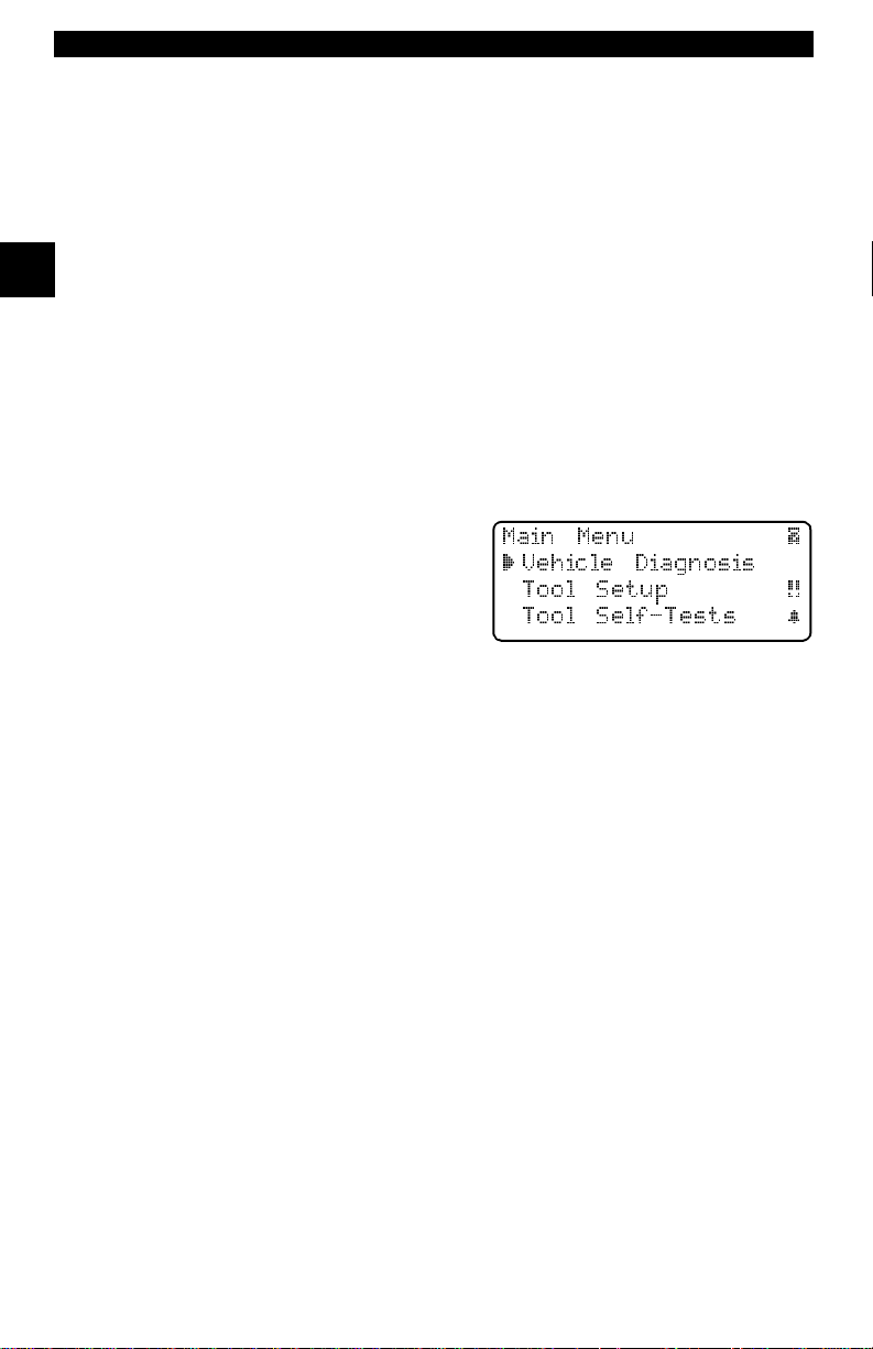
Screens
Certain Help mess ages, information, and dat a that are displayed on the scan
tool are also shown in graphical text boxes. The screens are presented as
examples and may change as the software is updated.
Example
Example
Example
:
:
:
Main Menu |
` Vehicle Diagnosis
Tool Setup [
Tool Self-Tests ~
1 – 2 • • • • • • • • • • • • • • • • • • • • • • • • • • • • • • • • • • • • • • • • • • • • • • • • • • • • • • • •
Page 15

Section 2 – Getting Started
The Professional Enhanced Scan Tool was developed by experts in the automotive servi ce industr y to help diagnose ve hicles and assist i n troubl eshooting
procedures. The tool monit ors vehicle e vents an d retrieves co des from t he vehicle computer’s memory to pinpoint problem areas.
All information, il lustrations and specifications contained in this manual are
based on the latest information available from indust ry sources at the time of
publication. No warranty (expressed or implied) can be made for its accur acy
or completeness , nor is any r esponsibilit y assumed by th e manufacturer or anyone connected with it for loss or damages suffered through reli ance on any
information conta ined i n t his manual o r misuse of acco mpan yin g produc t. The
manufacturer res erves the right to make changes at any time to this manual or
accompanyin g product without obligation to notify any person or organization
of such changes.
V EHICLE SERVICE INFORMATION
The following is a list of publi shers who have manuals containing el ectronic
engine control diagnost ic informat ion. Some m anuals may be availabl e at auto
parts stor es or your local public library. For others, you need to write for availability and pricing, specifying the make, model and year of your vehicle.
2
Chilton Book Company
Chilton Wa y
Radnor, PA 19089
Haynes Publications
861 Lawrence Drive
Newbury Park, CA 91320
Cordura Publications
Mitchell Manual s, Inc.
Post Office Box 26260
San Diego, CA 92126
Motor ís t Au to R ep a i r M a nu a l
Hearst Company
250 W. 55th Street
New York, NY 10019
General Motors Corporation:
Buick, Cadillac, Chevrolet, GEO, GMC,
Oldsmobile, & Pontiac
Helm Incorporated
Post Office Box 07130
Detroit, MI 48207
Saturn:
Adistra Corporation
c/o Saturn Publicat ions
101 Union St.
Post Office Box 100 0
Plymouth, MI 48170
Ford Motor Company:
Ford, Lincoln, & Mercury
Ford Publication Depar tment
Helm Incorporated
Post Office Box 07150
Detroit, MI 48207
Chrysler Corporation:
Chrysler, Plymouth, & Dodge
Chrysler Motors Service Training
26001 Lawrence Avenue
Center Line, MI 48015
INTRODUCTION TO ON-BOARD DIAGNOSTICS
Suitable manuals have titl es such as:
•“Electronic Engine Controls”
•“Fuel Injection and Feedback Carburetors”
•“Fuel Injection and Electronic Engine Controls”
•“Emissions Control Manual”
... or sim ila r titl es
• • • • • • • • • • • • • • • • • • • • • • • • • • • • • • • • • • • • • • • • • • • • • • • • • • • • • • • • • 2 – 1
Page 16

Getting Started
The original on-board diagnostics (OBD I) lacked consistency in communication and interfac e while allowin g different interpr etations am ongst vehicle m anufacturers. For d and Chr ysler used different types of engine cont rol comput ers
and data link conn ectors, and GM varied the tr ouble codes and communicat ion
protocols from year-to-year.
The tables belo w highl ight changes for GM, Ford, and Chrysl er. If this seems
confusing; d on’t worry. Your tool makes it easy. Based on the VI N information
selected during Scan Tool setup, the processor is aut omatically recogni zed. All
you have to do is choose the correct adapter cable and jumper wires (if necessary). Details on adapter cables and jumper wires may be found in “Diag-
nostic Link Connectors (DLC)” on page 2-3.
GM On-Board Diagnostics
2
System Years Description
Most vehicles u sed the 12 -pin AL DL (Asse m bly Li ne Data Li nk)
OBD I Control Module
OBD II Control Modul e
*
OBD II system used in certain 1994-1995 vehicles equipped with a 2.2L, 2.3L, 3.8L, 4.3L or 5.7L engines.
1981–199 5
1994*-Presen t Complies with OBD I I regulation s and us e s the J1 962 DLC.
located under the d ash on the driver side. S om e 94 -95 vehicles
used the 16-pin O B D II (J19 62) da ta link c onn ect or (DL C ), but
use the Historical application software. Refer to the vehicle’s
Vehicle Emission Control Information label.
Ford On-Board Diagnostics
System Long Na me Years Description
MCU
Microproc essor C o ntrol Unit 1980 –1991
EEC-IV
* EEC-V OBD II system used in 1994-1995 vehicles equipped with a 3.8L or 4.6L engine.
Elec tronic Engine Control,
Fourth gene ration
Mazda Electronic Control
MECS
System
Elec tronic Engine Control,
EEC-V
Fifth generation
Powertrain E lectron ic Co n-
PTEC
troller
1984 –1995
1988 –1995
1994* – present
2000 – presen t
Used in police vehicles, contai ning carbureted
engines. Uses the MCU DLC.
Most Ford ve hicles e quipped with North Am erican
engines. Uses the EEC- IV DLC.
Vehicles equ ipped with Mazda-sourced en gin es.
Uses MECS 6- pin and 17-pin DLCs.
Complies with O B D II regulations an d uses the
OBD II J1962 DLC.
Complies with O B D II regulations an d uses the
OBD II J1962 DLC.
Chrysler On-Board Diagnostics
System Long Na me Years Description
Single Module Engine
SMEC
Controller
Single Board Engine
SBEC
Controller
OBD II
OBD II Pow ert rain
PCM
Control Module
Jeep/T ruck Engi ne
JTEC
Controller
* In 1989, the SBEC system was installed in selected vehicles with 3.0L V6 engines.
** Some vehicles in 1995 were equipped with the OBD II PCM.
1989–199 0
1989*–19 95
1995**– present
1996– present
Used a 6-pin Serial Communication Interface (SCI) DLC
and has bidirectiona l cap ability.
Used two types of DLCs: a 6-pin SCI and a 6-pin LH
series.
The first to allow a tool to reset the EMR light on trucks.
Complies with O B D II regulations an d uses the O B D II
J1962 DLC .
Complies with O B D II regulations an d uses the O B D II
J1962 DLC .
The JTEC system is used on light-duty trucks and Jeeps
2 – 2 • • • • • • • • • • • • • • • • • • • • • • • • • • • • • • • • • • • • • • • • • • • • • • • • • • • • • • • •
Page 17

Getting Started
OBD II stands for O n-Boar d Diagnos tics ver sion I I. OBD I I is a syste m tha t the
Society of Autom otive Engineers (SAE) dev eloped to standardize automotive
electronic diagnosis. Technicians now can use the same tool to test any OBD
II compliant vehic les without special adapt ers. The SAE establish ed guidelines
that provide:
• a universal diagnostic test connector, c alled the data link connector (DLC),
with dedicated pin assi gnm ents.
• a standardized location for the DLC, visible under the dash on the driver’s
side.
• a standa rdi zed list of diagnostic trouble codes (DTCs) used by all manufacturers.
• a standardized list of parameter identification (PID) data used by all manufacturers.
• the ability of the vehicle system to recor d a freeze frame of the operati ng conditions when a fault occurs.
• expanded diagnostic capabilities that records a code whenever a condition
occurs that ef fects vehicle emissions.
• the ability to clear stored codes from vehicle memory with the scan tool.
In addition, SAE has published hundreds of pages of text defining a stan dard
communications protocol that establishes the hardware, software, and cir cuit
parameters of OBD II systems. Unfortunately , vehicle manufacturers have different interpr etations of this standard comm unications prot ocol. As a result, the
generic OBD II communic ations scheme us ed will vary, depending on t he vehicle.
SAE publishes r ecom m endations, not laws, bu t t he Environmental Protection
Agency (EPA) and California Air Resources Board (CARB) made many of
SAE’s recommenda ti ons legal requirements that vehicle manufacturers were
required to phase in over a three-year period. Beginni ng in 1994, vehicle s with
a new engine m anagement c omputer – about 1 0% of ea ch manufact urers fl eet
– were supposed to comply with O BD II standards. For 1995, OBD II systems
were to appear on about 40% of t he new vehic les sold in t he USA. Some of the
1994-1995 OBD II systems were not fully compliant, so the Government
granted waivers to give manufacturers time to fine-tune their systems. Beginning in 1996, m ost of the new vehicles sold in the USA were fully OBD II compliant.
2
DIAGNOSTIC LINK CONNECTORS (DLC)
The Data Link Connector (DLC) allows the scan to ol to communicate wit h the
vehicle’ s com puter(s). Before OBD II, manufactur ers used different data link
connectors to communicate with the vehicle. The proper DLC adapter cable
must be used to connect the tool to the ve hicle. Also , the vehi cle’s DLC may be
found in several different places and have many different configurations. The
following descri bes the DLCs used by Ford, GM and Chrysl er. The DLC lo cation
and types for domestic vehicles can be looked up in the charts in “Appendix
A - Data Link Connectors".
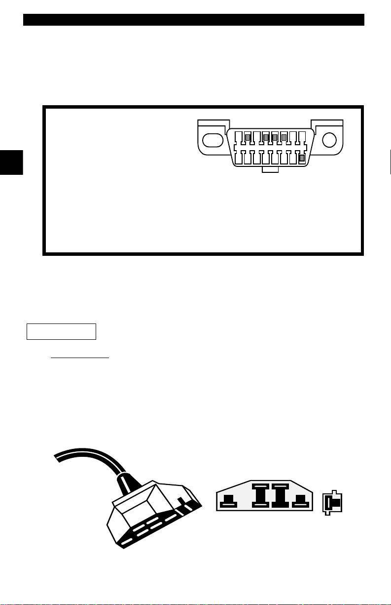
OBD II (J1962)
Beginning in 1996, vehicl es sold in
the United States use the J1962
(OBD II) DLC, a term taken from a
physical and el ectrical speci fication
number assigned by SAE (J1962).
The DLC should be located under
• • • • • • • • • • • • • • • • • • • • • • • • • • • • • • • • • • • • • • • • • • • • • • • • • • • • • • • • • 2 – 3
Page 18
Getting Started
the dashboard o n t he dri ver si de of the vehicl e. I f the DLC is n ot locat ed under
the dashboard as stated, a decal describing its location should be attached to
the dashboard in the area the DLC should have been located.
Because the OBD II J196 2 conn ector ha s power and ground , yo u only need a
single cable conn ection to the tool for both power and tool communi cations.
Attach the OBD II adapter cable to the extender cabl e, both supplied with the
tool, to connect the t ool. Certain pins in the connector are reserved.
2
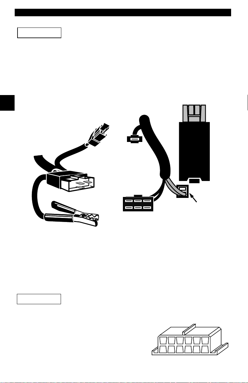
Ford Historic
IMPORTANT
EEC-IV/MCU
1 - Manufacturer Reserved
2 - J1850 Bus+
3 - Manufacturer Reserved
4 - Chassis Ground
5 - Signal Groun d
6 - CAN High, J-2284
7 - K Line, I SO 914 1- 2 & IS O/ DIS 14 230- 4
8 - Manufacturer Reserved
9 - Manufacturer Reserved
10 - J1850 Bus
11 - Manufacturer Reserved
12 - Manufacturer Reserved
1
9
13 - Manufacturer Reserved
14 - CAN Low, J-2284
15 - L Line, I SO 91 41-2 & ISO /DIS 14 230- 4
16 - Battery Power
8
16
Ford used three types of DLCs with their historic (OBD I) systems. Refer to
“Appendix A - Data Link Connectors" for the adapte r cable neede d for your
vehicle.
Use the Battery Power cab le to provi de power to the sca n tool
for all systems.
The EEC-IV/MCU DLC is a large si x-side d conn ector wi th a pi gtai l conne cto r .
The pigtail connector is not used on MCU vehicles – leave the pigtail unattached. The EEC-IV/MCU cable adapter is included with the scan tool.
Cable Adapter
EEC-IV/MCU
To Scan
Tool
Vehicle DLC
EEC-IV/MCU
STI Pigtail
EEC-IV
only
2 – 4 • • • • • • • • • • • • • • • • • • • • • • • • • • • • • • • • • • • • • • • • • • • • • • • • • • • • • • • •
Page 19
Getting Started
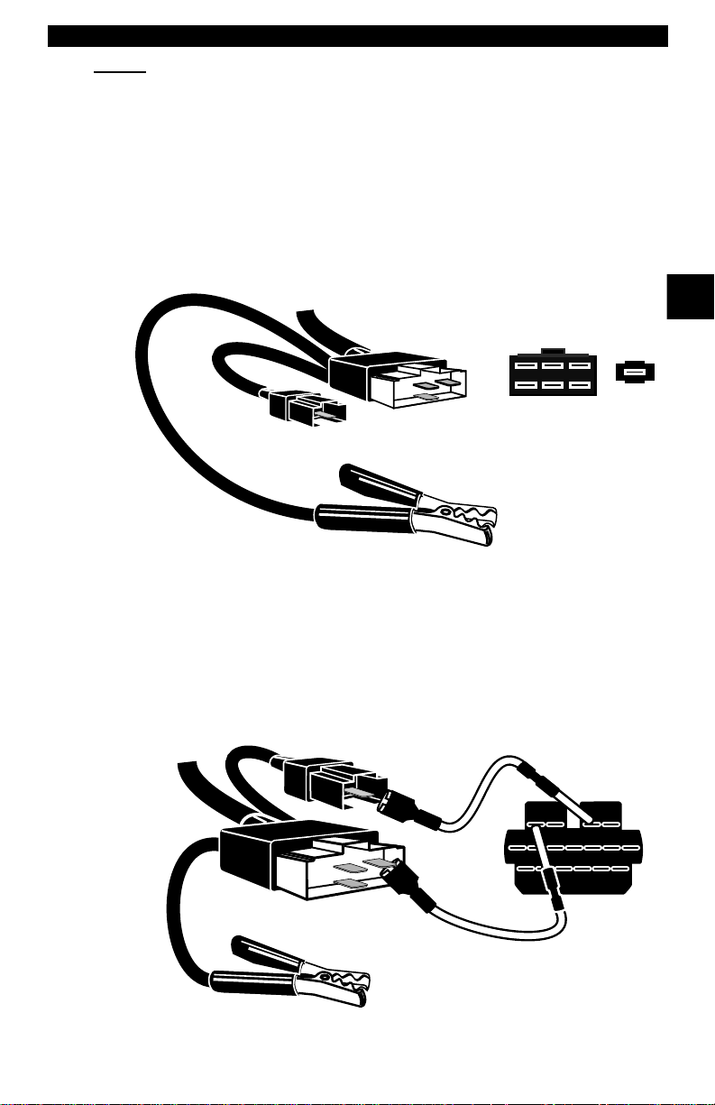
MECS
MECS vehicles (1988 –1995) use either a 6-pin (with pigtail) or a 17-pin DLC.
Use the MECS 6-pin adapte r cable k it (P/N 9603) fo r both con figur ation s. The
MECS adapter cable ki t includes jumpe r wires to connect to the MECS 17- pin
DLC. The MECS adapter cable kit is not included with this tool. It is available
through your dealer. Us e the following diagram s to connect the adapter cable.
6-Pin MECS
17-Pin MECS
To
Scan Tool
Cable Adapter
6-Pin MECS
P/N 9603
To Scan
To ol
STI Pigtail
Adapter Cable
6-Pin MECS
P/N 9603
STI Pigtail
Vehicle DLC
6-Pin MECS
2
Pigtail
6
5
4
3
2
1
Clip to good
Vehicle ground
Vehicle DLC
17-Pin MECS
4
1
3
2
6
5
STO
Clip to good
vehicle ground
• • • • • • • • • • • • • • • • • • • • • • • • • • • • • • • • • • • • • • • • • • • • • • • • • • • • • • • • • 2 – 5
Page 20
Getting Started
IMPORTANT
2
MECS Ford Probe
Certain Ford Probes have a WHITE TACH CONNECTOR
located very close to the 6-pi n Self-Test connec tor and
bundled in the same wiring harness. This is NOT the STI
(Self Test Input) Pigtail.
Connect the pigtail to the BLACK STI connector located fart her back on the wire
harness. If the tool is connec ted to the WHITE Tach co nnector , serious damage
will result and may void warranty. Refer to the illustration.
Cable Adapter
6-Pin MECS
P/N 9603
STI
Pigtail
Vehicle DLC
6-Pin MECS
To
Scan
Tool
GM Historic
Prior to1996, m ost GM vehicles us ed the 12-pin Assem bly Line Diagnosti c Link
(ALDL) DLC. The GM ALDL ca ble kit incl udes th e ALDL adapter and cigar ette
lighter power cable. This adapter cable is included with t he scan too. In 1994
and 1995, certain GM vehicles use the J1962 (OBD II) DLC, but are not OBD
II compliant. Refer to “Appendix A - Data Link Connectors".
IMPORTANT
The ALDL DLCs are usually located unde r
the dashboard on the driver’ s side.
On Corvettes & Fieros, the DLC may be
located in the center console behind the
ashtray . Refer to vehicle service manual for
exact locati on. I t may be in full view, or it
may be recessed behind a p anel. A n opening in the panel sho uld allow access to the recessed connect or.
Windshield
Wiper
Motor
WHITE
Tach
Connector
6
5
4
3
2
1
6-Pin MECS
BLACK STI
Connector
6-Pin MECS
DO NOT USE!
Clip to good
vehicle ground
Use the Battery Power cable to provide 12V to the tool.
ALDL
FGEHDJCKBLA
M
2 – 6 • • • • • • • • • • • • • • • • • • • • • • • • • • • • • • • • • • • • • • • • • • • • • • • • • • • • • • • •
Page 21
Getting Started
Chrysler Historic
Prior to 1996, most Chrys ler vehicl es use d either the SCI or LH DLC. Refer to
“Appendix A - Data Link Connectors" for DLC type and lo cation. The SCI
adapter cable is i ncluded with th e scan tool. The LH adapte r cab le (P/ N 9605)
can be purchased from your dealer.
IMPORTANT
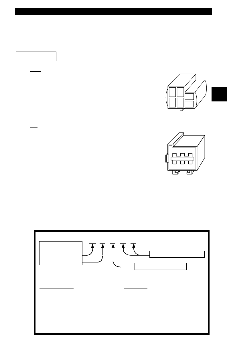
SCI
The SCI (serial communications interface) DLC is a
6-pin connector located in the engine compartment.
The adapter cable to be used on these vehicl es is supplied with the tool. This ca ble is labeled CHRY on the
15 pin DB styl e connec tor an d SCI on the veh icle end.
Use the Battery Power cable to provide 12V to the tool when
using the SCI adapter cable.
SCI
2
LH
The DLC is used on LH platform vehic les. The LH
style DLC is a small, blue, rectangular 6-pin connector located in the pas senger comp art ment belo w the
dashboard to the right of the steering column.
The LH Adapter Cable (P/N 9605) is optional and
must be purchased separately.
DIAGNOSTIC TROUBLE CODES (DTCS)
Diagnostic T rouble Codes (DTCs) consist of a five-digit alphanumeric code.
The DTC format and gener al code typ es are shown bel ow . When the on-b oard
computer recogni zes and identifi es a probl em, a DTC for t hat fault is stor ed in
memory. These codes are intended to help you determine the root cause of a
problem.
Bx - Body
Cx - Chassis
Px - Powert rain
Ux - Network Comm.
x = 0, 1, 2 or 3
Example:
P0101 - Mass or Volume Air Flow Circuit Range/Performance Problem
Powertrain Codes
P0xxx - Generic (SAE)
P1xxx - Manufacturer Specific
P2xxx - Generic (SAE)
P30xx-P33xx - Manufacturer Specific
P34xx-P39xx - Generic (SAE)
Chassis Codes
C0xxx - Generic (SAE)
C1xxx - Manufacturer Specific
C2xxx - Manufacturer Specific
C3xxx - Generic (SAE)
P 0 1 0 1
Body Codes
B0xxx - Generic (SAE)
B1xxx - Manufacturer Specific
B2xxx - Manufacturer Specific
B3xxx - Generic (SAE)
Network Communication Codes
U0xxx - Generic (SAE)
U1xxx - Manufacturer Specific
U2xxx - Manufacturer Specific
U3xxx - Generic (SAE)
Specific Fault Designation
Vehicle Specific System
LH (P/N 9605)
• • • • • • • • • • • • • • • • • • • • • • • • • • • • • • • • • • • • • • • • • • • • • • • • • • • • • • • • • 2 – 7
Page 22
Getting Started
y
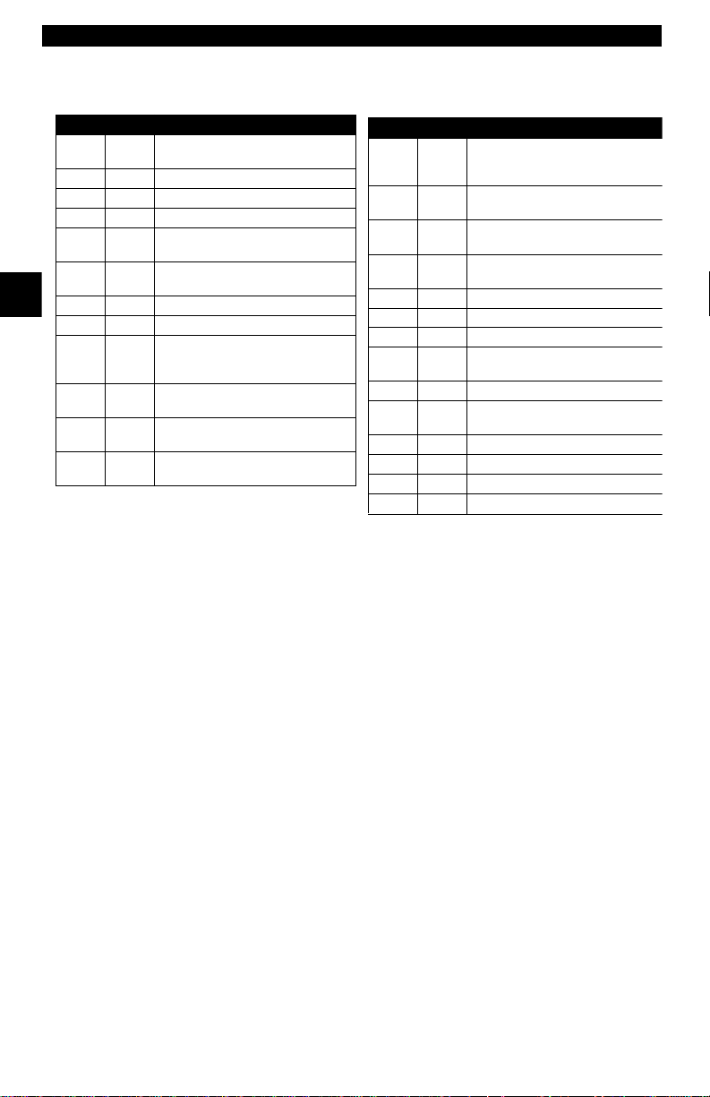
Within each general category, th e DTCs are assi gned to specific ranges that
cover certain vehicle systems.
Lower Upper Assigned DTC Syste m
Fuel Air Metering Auxiliary
Emission Controls
Fuel Air Metering
Ignition System or Misfire
Auxiliary Em is sion Contr o ls
Vehicle Speed Idle Speed Con-
trol Auxiliary Inputs
Computer and Auxiliary Out-
puts
Transmission
Hybrid Propulsion
Manufacturer Control Fuel & Air
Meterin g, Auxil ia ry Emis sion
Controls
Manufacturer Control Fuel & Air
Metering
Manufacturer Control Ignition
System or Misfire
Manufacturer Control Auxiliary
emission Controls
2
P0000 P00FF
P0100 P02FF
P0300 P03FF
P0400 P04FF
P0500 P05FF
P0600 P06FF
P0700 P09FF
P0A00 P0AFF
P1000 P10FF
P1100 P12FF
P1300 P13FF
P1400 P14FF
J2012 and ISO 15031-6 are standards for all DTCs, established by the SAE,
International Organization for S tandardization (ISO) and other governing bodies. Codes and the definitions assigned by this specification are known as
Generic OBD II codes. OBD II requi res compliance of this standard, and has
made it a standard for all cars , light t rucks , APVs, MPVs, an d SUVs so ld in t he
U.S. Codes not reserved by the SAE are reserved for the manufacturer and
referred to as Manuf acturer Specific.
Lower Upper Assigned DTC Syste m
Manufacturer Cntrl Veh.Spd.
P1500 P15FF
P1600 P16FF
P1700 P19FF
P2000 P22FF
P2300 P23FF
P2400 P24FF
P2500 P25FF
P2600 P26FF
P2700 P27FF
P2900 P32FF
P3300 P33FF
P3400 P34FF
U0000 U00FF
U0100 U02FF
Idle Speed Cont rol Auxiliary
Inputs
Manufacturer Control Auxiliar
Inputs Auxiliar y Outputs
Manufacturer Control Transmission
Fuel Air Metering Auxiliary
emission Controls
Ignition System or Misfire
Auxiliary Emission Controls
Auxiliary Inputs
Computer and Aux iliary Out -
puts
Transmission
Fuel Air Metering Auxiliary
Emission Controls
Ignition System or
Cylinder Deactivation
Network Electrical
Network Communication
2 – 8 • • • • • • • • • • • • • • • • • • • • • • • • • • • • • • • • • • • • • • • • • • • • • • • • • • • • • • • •
Page 23
Section 3 – Using The Scan Tool
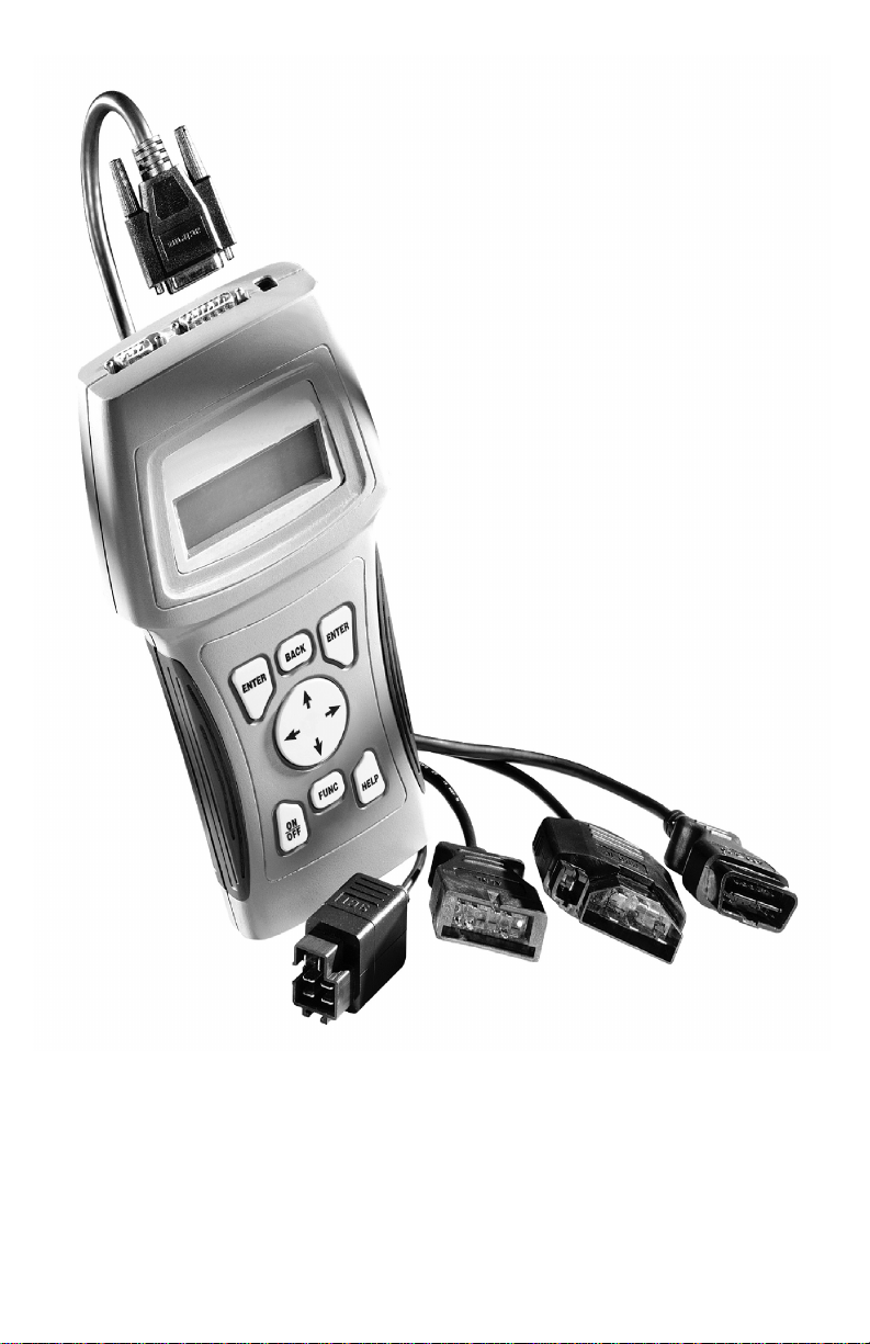
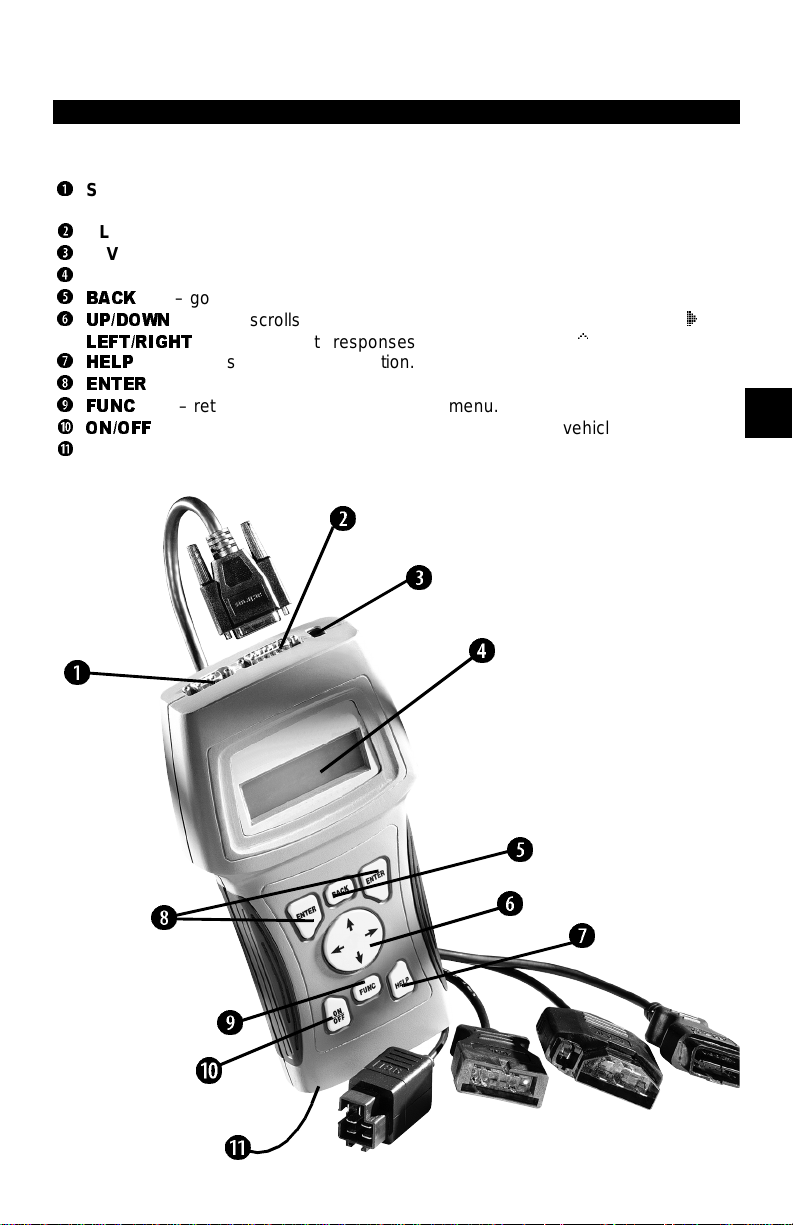
THE SCAN TOOL
B
Serial Port (DB9 Male Connector) – provides a serial RS232 connection for a prin ter
and for updating the soft ware.
C
DLC Port (DB15 Male Connector) – provides connection for vehicle interface.
D
12V Power Jack
E
LCD Display – backlit, 4 li ne x 20 character with contrast adjustment.
F
BACK
key – goes to the previous screen or level.
G
UP/DOWN
LEFT/RIGHT
H
HELP
I
ENTER
J
FUNC
a
ON/OFF
b
Battery compartment cover.
B
arrows – scrolls UP or DOWN and moves the selection pointer (`).
key – accesses the Help Functi on.
arrows – selects responses and moves cursor (^) in code lookup.
key – selects displa yed items.
key – returns back to a function li st or menu.
key – turns power ON/OFF when not connected to vehicle.
C
D
E
3
F
I
G
H
j
a
b
• • • • • • • • • • • • • • • • • • • • • • • • • • • • • • • • • • • • • • • • • • • • • • • • • • • • • • • • • 3 – 1
Page 24
Using The Scan Too l
Specifications
Display: Backlit LCD, 4 line, 20 column, contrast adjust
Operating Temperature: 0 to 50°C (32 to 122°F)
Storage Temperature: -20 to 70°C (-4 to 158°F)
Intern a l P o w e r: 6-AAA cells
External Power: 6.5 to 15 .5 Volts
✓ Most vehicle control modul es require at least 8.0 V to operate properly.
Power Dissipation: 3.5 Watts maximum
Dimensions: Height
1.625" 5.25" 9.75"
41 mm 133 mm 248 mm
Weight: 3.16 lb s (1432 g)
Accessories
3
Stan dard 8 ft Extender Cable
Battery Power Cable (includes cigarette lighter adapter)
– included with adapter cable kits
– Battery Clip Adapter — Optional
Adapter Cables: Standard OBD II (J1962) cable — Included
GM ALDL cable kit — Included
Ford EEC-IV/MCU cable kit — Included
Chrysler SCI cable kit — Included
9605 Chrysler LH cable kit — Optional
9603 Ford Probe/MECS cable kit — Optional
Optional / Replacement Parts are available from the:
• dealer where you originally purchased your tool.
• manufactur er cont act cust omer se rvice at 1-800-228-7667 (8:00 – 6:00 EST
Monday – Friday) or send an email to tech_support@actron.com.
Display
The scan tool uses a 4 line by 20 character, back-li t Liquid Crystal Display
(LCD). The l arge viewing area di splays mess ages, ins tructio ns, and di agnostic
informatio n. The contrast can be adjusted.
Seven charact ers help you nav igate and
operate the scan too l:
|
appears in upper right corner o f display to indicate Hel p is available.
`
identifies the selection.
[
indicates additional information is
available on the ne xt screen.
]
indicates additional information is available on the previous screen.
«
identifies selected items in data lists.
~
Bell in lower right corner means the sound alert is on or active.
Low battery symbol will appear i n bottom rig ht-hand corner of the screen at
power-up if the inte rnal batteries need replacement or are not installed.
Keyboard
The scan tool’ s software is designed for ease in operat ing and navigating
through menus. Do not use s olvents such as alco hol to cl ean the keyp ad or display . Use a mi ld nonabrasive de tergent and a soft cot ton cloth. Do not soak th e
keypad as water might find its way inside the scan tool.
3 – 2 • • • • • • • • • • • • • • • • • • • • • • • • • • • • • • • • • • • • • • • • • • • • • • • • • • • • • • • •
Width Length
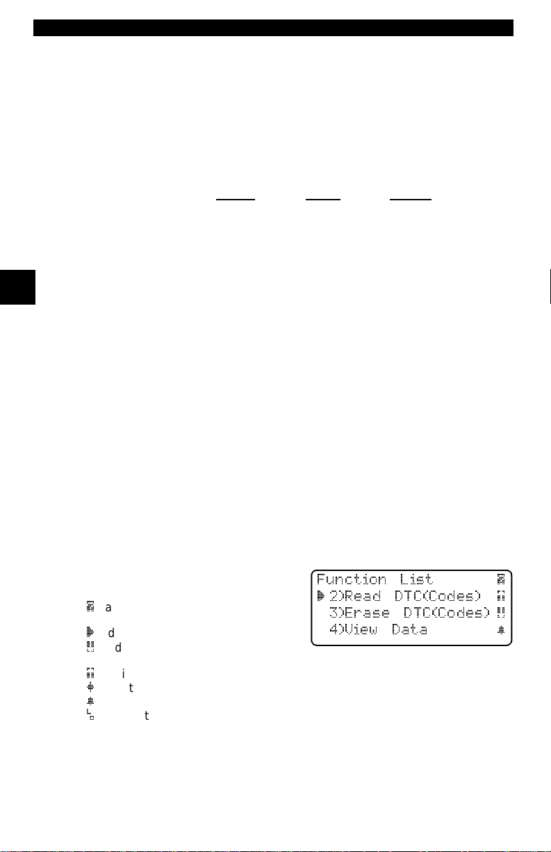
Function List |
` 2)Read DTC(Codes) ]
3)Erase DTC(Codes) [
4)View Data ~
Page 25
Using The Scan Tool
Power
✓ Refer to “Scan Tool Does Not Power Up” on page 8-1 if you encounter
problems.
Internal Batteries
When the scan tool is no t connect ed to the ve hicle , the
the scan tool . Press and hold do wn th e
turn ON the scan tool.
To conserve battery power, the scan tool disab les the display’s back-lighting
and turns OFF after a period of inactivity.
Each time the s can tool is p owere d up, t he v olt age of t he b atter ies i s checke d.
If the voltag e is low, t he Low Battery Symbol (
batteries using the instructions provided in “Battery Replacement” on
page 4-3.
ON/OFF
) displays on the screen. Replace
ON/OFF
key for at l east o ne se cond to
✓ If the scan tool wi ll not be used for an extended period of time, rem ove the
batteries to prevent electrolyte leakage from damaging the battery compartment.
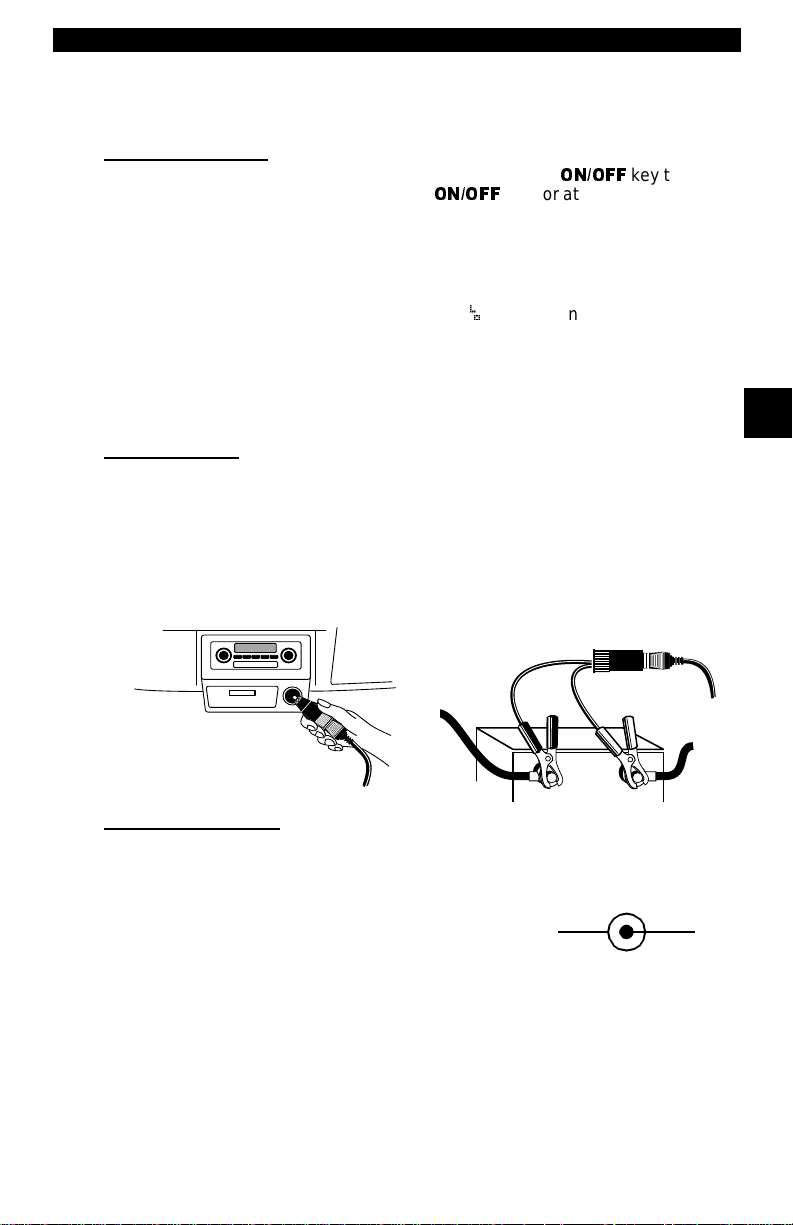
Vehicle Power
When using the OB D II J1962 or Chry sler LH adapte r cabl es, th e powe r to t he
tool comes from vehicle Dat a Link Connector (DLC). All other vehicles will
require power connec tion to the cigarette light er, acces sory plug, or the vehicl e
battery using battery clip adapters. If you are unsure of what DLC adapter to
use, then refer to “Appendix A - Data Link Connectors".
Some vehicle ci garette lighters are not po wered when the ignit ion is i n the OFF
position. Therefore, you may wish to use battery clip adapt ers.
Batter y Clip A da p ter (op t io na l)
key turns ON
3
Cigarette Lighter Adapter
AC Power Adapter
An AC power adapter (not incl uded) can be used to power the t ool when reprogramming from a per sonal comput er or off-vehi cle reviewing of codes and print ing. 12V AC-DC converters are available at most PC and electronic stores.
The tool is equipped to accept any 110 Vac - 12
Vdc wall adapter wit h the following specificat ions:
• 300 mA minimum current unregulated wall
power adapter.
• Adapter Dimensions: 5.5 mm Outside Diameter
• 2.5 mm Inside Diameter
• The Inside Tip is positive (+).
• • • • • • • • • • • • • • • • • • • • • • • • • • • • • • • • • • • • • • • • • • • • • • • • • • • • • • • • • 3 – 3
12 VGND
Page 26
Using The Scan Too l
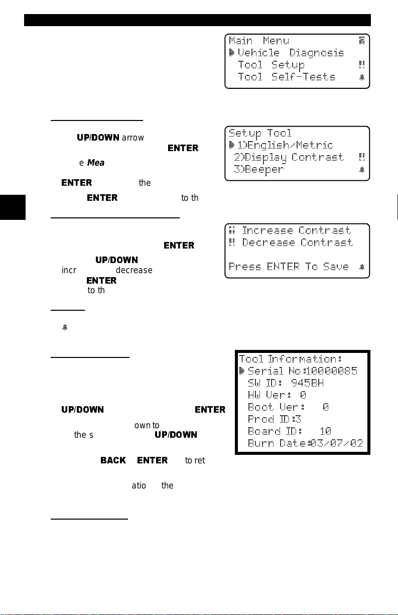
Scan Tool Setup
Tool Setup allows you to change the
measurement units and LCD contrast,
turn beeper On/Off and display tool
informatio n. The set tings remain until
the internal batteries become discharged.
Measurement Units
T o ch ange t he measur ement unit s, use
the
UP/DOWN
English/Metric and pre ss
In the
select English or Metric and then press
ENTER
Press
3
Changing Display Contrast
The display contr ast can be adjusted
from the
play Contrast and press
Use the
increase and decrease the contrast.
Press
return to the
Beeper
Beeper selection a llows the user to turn Off the tool ’s beeper. The bell symbol
~
will not appea r in t he lower right han d corner of th e displ ay wh en the be eper
is off.
Tool Information
This function allows you to view specific
tool informati on that may be needed when
contacting customer service.
Select Tool Information with th e
UP/DOWN
The information shown t o the right displays
on the screen. Use the
keys to view all the lines.
Press the
the
Setup Tool
✓ Write this inform ation in the space provi ded on the inside of the front cov er.
arrow keys to select
Measurement Units
. English is the default.
ENTER
ENTER
again to re tu rn to th e
Tool Setup
UP/DOWN
Setup Tool
arrow keys and press
BACK
menu. Sele ct Dis-
arrow keys to
to save the setting and to
or
menu.
menu.
UP/DOWN
ENTER
ENTER
ENTER
key to return to
.
menu,
Setup Tool
.
ENTER
arrow
Main Menu |
` Vehicle Diagnosis
Tool Setup [
Tool Self-Tests ~
Setup Tool
` 1)English/Metric
2)Display Contrast [
3)Beeper ~
menu.
] Increase Contrast
[ Decrease Contrast
Press ENTER To Save ~
Tool Information:
` Serial No:10000085
SW ID: 945BH
HW Ver: 0
Boot Ver: 0
.
Prod ID:3
Board ID: 10
Burn Date:03/07/02
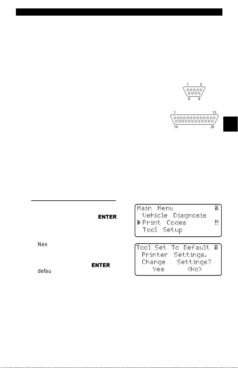
Printer Interface
The scan tool is designed as a Data Terminal Equipment (DTE) dev ice with a
DB9M (9-pin D-shape male) connector to interface with a compatibl e serial
printer.
Compatible Printers
The printer must have a ser ial RS- 232 inte rface c ircui t and be comp at ible wit h
the Epson FX format. The following printers are recommended:
3 – 4 • • • • • • • • • • • • • • • • • • • • • • • • • • • • • • • • • • • • • • • • • • • • • • • • • • • • • • • •
Page 27
Using The Scan Tool
❒ Seiko DPU-414
❒ Kodak DICONIX 180si (seri al printer model)
❒ Lexmark Model 2480 with optional serial interface (p/n 12T0154)
❒ Panasonic KX-P1131 printer
Cabling
❒ Type: A standard RS-232 type cable.
❒ Scan Tool end: DB9F (female) connector.
❒ Printer end:
• Use a DB9M (male) connec-t or for the Seiko and
Kodak printers.
• Use a DB25 male connector f or the Lexmark and
Panasonic printers.
• If the printer uses a di fferent connector, then an
adapter or different RS-232 cable is required.
Adapters are available at most local PC stores or
electronics outlets.
Serial Port Settings
❒ Default settings for the scan tool are: 9600 Baud, 8 Data Bits, No Parity
and 1 Stop Bit.
❒ Ensure the settings on the scan tool and printer match .
❒ For the Lexmark and Panasonic printers, ensure the pri nter’s interface
selection is set to either “auto” or “serial”.
The printer and scan tool must have t he same comm unication sett ings. Y ou c an
change the scan tool’s settings if necessary.
Changing the Printer Settings
Select either Print Codes from the
Main Menu
Function List
or Print D ata from of the
and press
ENTER
DB9
DB25
3
Main Menu |
.
Vehicle Diagnosis
` Print Codes [
Tool Setup
Next, the tool will inform you of the
printer setti ngs (Custom or Default),
then ask if you wish to change them.
Select YES and press
default values are desi gnated on the display with the word (Default) next to the
option.
Refer to the printer manu al for the settings. The changes made res ide in the tool
even when the tool is turned of f.
Tool settings are as follows. Defaults are in [ . . . ]
ENTER
.The
Tool Set To Default |
Printer Settings.
Change Settings?
Yes <No>
❒ Baud Rate: [9,6 00], 1200, 2400
❒ Stop Bits: [1 Bit], 2 bits
❒ Parity: [None], Odd, Even
❒ Printer Speed: [Fast], Slow
• • • • • • • • • • • • • • • • • • • • • • • • • • • • • • • • • • • • • • • • • • • • • • • • • • • • • • • • • 3 – 5
Page 28
Using The Scan Too l
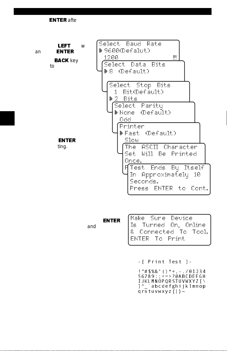
Press
ENTER
the screens. For the printer to work pro perly , the tool and the printer must be set
to the same configur ati on. Change the settings accordingly.
To change the settings,
press the
and then
Use the
return to the previous
menu.
LEFT
ENTER
BACK
after s electin g each sett ing. Fol low the i nstructions displaye d on
arrow
.
key to
Select Baud Rate
` 9600(Defalut)
1200 [
2400
Select Data Bits
` 8 (Default)
The new printer setti ngs
are tested by pr inting t he
ASCII character set.
Press to continue .
Select Stop Bits
1 Bit(Default)
`2 Bits
Select Parity
` None (Default)
3
Make sure print er is
turned ON, ONLINE and
connected to the too l.
Press the
begin printing.
ENTER
key to
Odd
Even
Printer
` Fast (Default)
Slow
The ASCII Characte r
Set Will Be Printed
Once.
Press ENTER to Cont.
Test Ends By Itself
In Approximately 10
Seconds.
Press ENT ER t o C ont .
If the printout is not OK, then retry or
change settings. If it is, press
and the data transmits and prints.
ENTER
Make Sure Device
Is Turned On, Online
& Connected To Tool.
ENTER To Print
A printout of the test looks similar to the
example shown.
3 – 6 • • • • • • • • • • • • • • • • • • • • • • • • • • • • • • • • • • • • • • • • • • • • • • • • • • • • • • • •
-[ Print Test ]-
!"#$%&'()*+,-./01234
56789:;<=>?@ABCDEFGH
IJKLMNOPQRSTUVWXYZ[\
]^_`abcdefghijklmnop
qrstuvwxyz{|}~
Page 29
Using The Scan Tool
Diagnostic
Connector
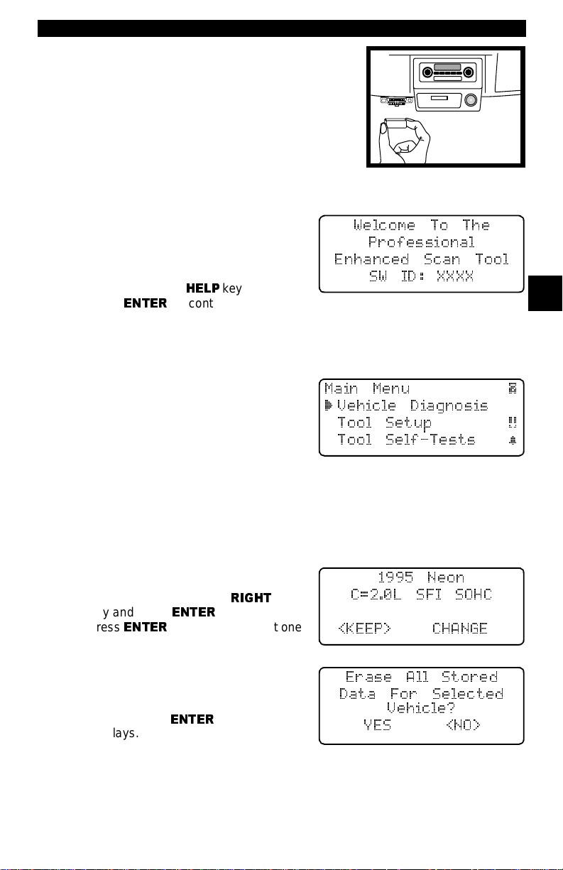
CONNECTING THE SCAN TOOL
To diagnose a vehicle, connect the DLC and
power adapter (if applicable) to the scan tool.
Refer to “Diagnostic Link Connectors (DLC)”
on page 2-3 of Getting St arted.
If you just want to power up the tool to do its
self-tests, code lookup, review or printing data
from the last vehicle t ested, then you do not need
to attach the cable to the Data Link Connector . The internal battery provides
power fo r th is .
When the scan tool powers u p, a series
of messages display on the screen
beginning with a “Welcome” scr een and
ending with a “Key Bu tton Help” scr een.
If you wish to re vie w the key button def initions, pus h the
press
ENTER
Veh icle Sel ectio n
When the tool powers up, the “Key Butt on Help” screen is fol lowed by a
Menu
screen.
Pick Vehicle Di agnosis to begin Vehi-
cle Selection. I f there is a pr evious vehi cle present, the tool displays that
vehicle. Y o u can choose the l ast vehicle
selected or set up for a new vehicle. The
tool retains all data retrieved from the
last vehicle select ed until any of the fol lowing occurs:
❒ A new vehicle is selected
❒ Internal AAA batteries are depleted or disconnect ed
❒ Tool is flash pro grammed to update software
❒ The last vehicle selected is kept but you choose Erase Data
You can either keep the previously
selected vehicle or change it. If changing the vehi cle, press t he
key and press
press
ENTER
Keep Current Vehicle
The next screen asks if you want t o
erase the stored data. The default is
NO.
After pressing
displays.
HELP
key; othe rwise,
to continue.
RIGHT
arrow
ENTER
. Otherwise,
to keep the current one.
ENTER
, the functi on li st
Main Menu |
` Vehicle Diagnosis
<KEEP> CHANGE
Welcome To The
Professional
Enhanced Scan Tool
SW ID: XXXX
3
Main
Tool Setup [
Tool Self-Tests ~
1995 Neon
C=2.0L SFI SOHC
Erase All Stored
Data For Selected
Vehicle?
YES <NO>
• • • • • • • • • • • • • • • • • • • • • • • • • • • • • • • • • • • • • • • • • • • • • • • • • • • • • • • • • 3 – 7
Page 30
Using The Scan Too l
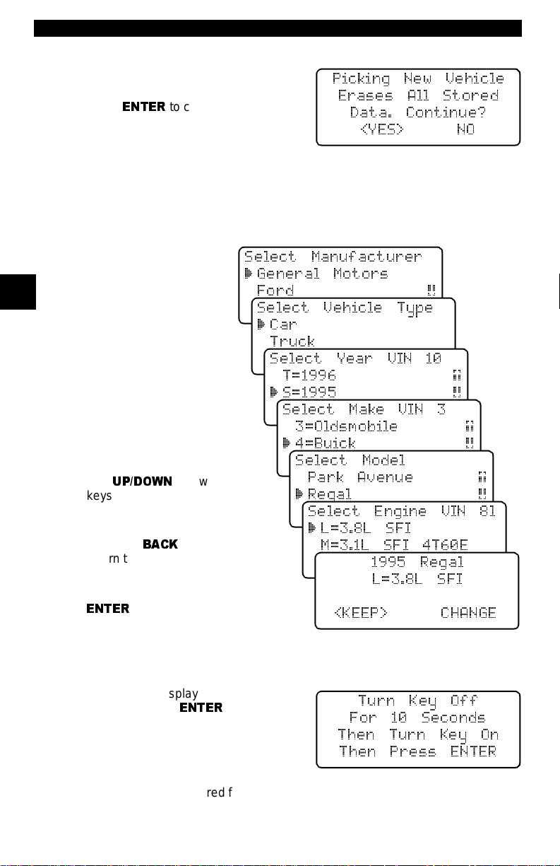
Chan ging the Vehicle
Changing vehicl es erases all data
stored in the tool. The default is YES.
Press
ENTER
Four V ehicle Op tions are avai lable: General Motor s, Ford, Ch rysler and Glo bal
OBD II. Global OBD II does not require additional information and takes you
directly to th e function list . The other three requ ire additional inf ormation so that
the tool can communicate with the vehicle. For example, selec t GENERAL
MOTORS.
The menus provide a list
of choices and reference
the vehicle’s VIN where
3
applicable. The VI N is visible fro m outsid e the vehi cle by looking thr ough the
base of the front windshield at the top of the
dashboard on the dr iver’s
side. Because manufacturers use diff erent VIN
schemes, the tool will
indicate which d igit of the
VIN to loca t e fo r info r m a tion such as Year, Make
and Engine.
Use
UP/DOWN
keys to move through the
list.
If you make a mistake,
press the
return to the previous
menu.
At the last screen, press
ENTER
BACK
.
to continue.
arrow
key to
Picking New Vehicle
Erases All Stored
Data. Continue?
<YES> NO
Select Manufacturer
` General Motors
Ford [
Chrysler
Select Vehicle Type
` Car
Truck
Select Year VIN 10
T=1996 ]
` S=1995 [
R=1994
Select Make VIN 3
3=Oldsmobile ]
` 4=Buick [
6=Cadillac
Select Model
Park Avenue ]
` Regal [
Reviera
Select Engine VIN 8l
` L=3.8L SFI
M=3.1L SFI 4T60E
M=3.1L SFI AUTO-3S
1995 Regal
L=3.8L SFI
<KEEP> CHANGE
If a message displays , follow the instructions then press
ENTER
.
Turn Key Off
For 10 Seconds
Then Turn Key On
Then Press ENTER
✓ Vehicles manufactured from 2000 to present automatically use G lobal OBD
II Diagnostics even if GM, Ford or Chrysler was selected.
3 – 8 • • • • • • • • • • • • • • • • • • • • • • • • • • • • • • • • • • • • • • • • • • • • • • • • • • • • • • • •
Page 31

Using The Scan Tool
User Interface
The scan tool i s designed t o be as intuit ive as possi ble. All m enu and list s operate the same way. Use the
the display or move t he cursor (
to select the functi on or item. To return to previous screens , pr ess the
key . This informat ion can be viewed on t he sca n tool by pressing the
after powering up the scan tool.
If a list or message c ontains more than f our lin es, an arr ow icon di splays on t he
last column o f the di splay to indi cate t he scr olli ng direct ion a vaila ble: up (
down (
[
play . When the bott om of the list i s reached , then on ly the
of the list, only the
For example: to read DTCs stored i n the
vehicle, move the cursor to Read
Codes with th e
and press
choice, such as viewing data, use the
UP/DOWN
sor down to View Data and press
ENTER
). Use the
.
User Responses
The scan tool may ask a questi on which
requires a YES or NO response —
brackets (
To accept the default choice, press the
ENTER
press the
ets to another re sponse and press
key. T o change the answer,
HELP
UP/DOWN
`
) to a selectable it em. Press t he
UP/DOWN
[
displays.
UP/DOWN
ENTER
<>
. To make a different
arrow keys to move the cur-
) enclose the defaul t one.
key to move the brack-
arrow keys to move line-by-line through the di s-
arrow keys
ENTER
arrow keys to m ove
UP/DOWN
ENTER
]
displays. At the top
Function List |
` 3)Erase DTC(Codes) ]
4)View Data [
5)View Freeze Data ~
View Instructions
For Creating Custom
Data List?
Yes <No> ~
.
through
BACK
HELP
]
key
key
) or
3
Viewing Data
Viewing dat a allows you to obs erve sensor data and the oper ation of switche s,
solenoids, a nd rel ays. As the compu ter
monitors the vehicle, the parameter
Identificati on (PID) data is transmitted to
the scan tool.
For viewing options, select View Data from the
ENTER
.
Entire Data List
The Entire Data List shows all sup-
ported parameter id entifica tion (PID)
data for the v ehi cle be ing t est ed. When
the scan tool makes a recording, the
data from al l support ed PIDs are stor ed
in the scan tool.
• • • • • • • • • • • • • • • • • • • • • • • • • • • • • • • • • • • • • • • • • • • • • • • • • • • • • • • • • 3 – 9
Function List |
3)Erase DTC(Codes) ]
` 4)View Data [
5)View Freeze Data ~
Function List
and press
Select Data To View
` Entire Data List
Custom Data List
View Data Setup ~
Page 32

Using The Scan Too l
Custom Data List
The Custom Data List allows you to
select certai n PIDs from the Entire Data
List, such as those PI Ds t hat pert ain to
a specific driveability symptom or system. The scan tool asks if you want to
view the instructions.
Once in the
follow the i nst ructions des cribed below.
A
«
symbol will be displ ayed next to all
selected PIDs. Use the
arrow keys to scroll through the list.
Custom Data List
UP/DOWN
menu,
View Instructions
For Creating Custom
Data List?
YES <NO> ~
Select Custom List
« MIL STATUS
ABSLT TPS(%) [
` ENGINE(RPM) ~
• Use the
•
UP
•
3
DOWN
•
RIGHT
ues are marked with
LEFT
•
•
ENTER
data pa r a m e ters .
Once in the Custom Data List selection screens, follow the instructions
described above to buil d a Custom Data List. Data parameter s or Parameter
Identificat ion Data (PID) will follow in alphabeti cal order . Refer t o “Appendix C
- PID Lis t " for a complete list ing of all PIDs.
When you are don e sele cting the PI Ds, pr ess the
PID values. Press the
menu.
UP/DOWN
arrow: Moves the cursor up the data list.
arrow: Moves the cursor down the data list.
arrow: Selects or deselects a data param eter. All select ed data val-
arrow: Desele cts all marked data parameters.
key: S tarts p laying back data , recording da ta, or displayi ng selected
View Da ta Se t up
View Data Setup changes the numbe r
of lines sh own on the scr een. Sel ecti ng
fewer lines provides faster update
speeds. The default is four-line display.
arrow keys to move up and down through the list.
«
symbol.
BACK
key twice to return to the
ENTER
key to view selected
Select Data To View
Select Data To View
Entire Data List
Custom Data List
` View Data Setup ~
3 – 10 • • • • • • • • • • • • • • • • • • • • • • • • • • • • • • • • • • • • • • • • • • • • • • • • • • • • • • •
Page 33

Section 4 – Global OBD II Diagnostics
The first time the scan tool communi cates with the veh icle, th e communicatio n
type is automat ical ly det ected, and is u sed u ntil th e sca n tool is tur ned OF F or
another vehicle is diagnosed.
✓ If an Error Message displays, make sure the OBD II connector is
securely attached, and the ignition key is ON. Cycle the ignition key to
OFF for 10 sec onds, then ON. This may b e required t o reset the computer .
If required, select Y ES t o try again. I f the problem s till exist s, refer to “Error
Messages” on page 8-2.
✓ On the initial link to the vehicle, the scan tool checks the status of the
I/M Monitors and conveys it to the operator, no matter which function is
selected.
MANUAL INFO
The Manual Info function, the last one in the f unction list, inst ructs the user what
section of t he manu al to u se. Thi s se ction covers Global OBD II Diagnos tics .
I/M READINESS
The I/M Readiness (Inspe cti on and Maintenance) function displays the st ate
of the vehicle ’s OBD II Moni tors. Monitor s are test s designed t o verify t he operation of emis sion related systems o r components and detect out-of-range values. The vehicle may have to be operated under certain driving conditions to
initiate a moni t or . I f the vehi cle l ose s elect ric al power or code s ar e erase d, the
monitors may be cleared. This function can be performed with the key ON —
engine OFF (KOEO) or key ON — engine Running (KOER).
The abbreviation s and names fo r the OBD II Moni tors suppor ted by this tool are
shown in the following lis t. They are required by the U.S. Environmental Protection Agency (EPA). Not all monitors are supported by all vehicles.
Abbreviated Name
Misfire Monitor ..............................Misfire Monitor
Fuel System Mon .........................Fuel System Monitor
Com Component..........................Comprehensive Component s Monitor
Catalyst Mon ................................Catalyst Monitor
Htd Catalyst..................................Heated Catalyst Monitor
Evap System Mon.......... ..............Evaporative System Monitor
Sec Air System............... .............Secondary Air System Monit or
A/C Refrig Mon.............................Air Conditioning Refrigerant Monitor
Oxygen Sens Mon................. .. ....Oxygen Sensor Monitor
Oxygen Sens Htr.............. .. .........Oxygen Heater Sensor Monitor
EGR System Mon ................ .... ....Exhaust Gas Recirc ulati on Syst em Moni tor
The vehicle may support two types of I/M Readiness:
❒
SINCE DTCs CLEARED
DTCs were last erased.
❒
THIS DRIVING CYCLE
of the current drive cycle.
If the monitors ar e not supported for
only shows monitors for
Expanded Name
shows the status of the monitors since the
shows the status of the monitors since the start
THIS DRIVING CYCLE
SINCE DTCs CLEARED
with no header on line 1.
, then the scan tool
4
• • • • • • • • • • • • • • • • • • • • • • • • • • • • • • • • • • • • • • • • • • • • • • • • • • • • • • • • • 4 – 1
Page 34

Global OBD II Diagnos t ic s
Select I/M Readiness from the
Function List
The scan tool displays a message stating whether the I/M Readi ness monitors
are completed.
menu and press
OBDII
ENTER
OBDII Function List |
.
` 1)I/M Readiness
2)Read Codes [
3)Pending Codes ~
Use the
supported, t hen use the
types.
4
4
• A status of “OK” means that the re quired driv ing c onditi ons f or that monito r
• A status of “Inc” means tha t the required driving conditions for that monitor
• A status of “N/A” mean s the vehicle does not support that monitor.
When done, press the
READ CODES
The Read Codes function retrieves Diagnos tic Trou ble Codes (DTCs) from th e
vehicle’ s compute r modul e(s). Thi s funct ion can be per f ormed with the KOEO
or KOER.
These codes cause t he c omputer t o illuminate the Malfunction Indicator Lamp
(MIL) when an emissi on-related or driveability faul t occurs. The MIL is also
known as the “service engine soon” or “check engine” lamp.
Select Read Codes and press
The Scan Tool retrieves the DTCs
stored in the veh icl e’s computer module(s).
On-Board Readiness |
Tests Are Complete
Not All Supported
On-Board Readiness
Tests Are Complete.
Use [ To View Test~
DOWN
arrow key to view the monitor stat uses. If both monitor types are
LEFT/RIGHT
Use [ To View ~
arrow keys to toggle between monitor
THIS DRIVING CYCLE
Misfire Monitor n/a
Fuel System Mon ok [
Catalyst Mon inc ~
have been met and the monitor passed.
have not been met or the monit or did not pass.
BACK
key to retur n to th e
ENTER
Misfire Monitor ok
Fuel System Mon ok [
Catalyst Mon inc~
.
OBDII Function List |
1)I/M Readiness
` 2)Read Codes [
3)Pending Codes ~
SINCE DTCS CLEARED
OBDII Function List
.
The Scan Tool displays the DTCs or a message st ating SYSTEM PASS: NO
CODES FOUND. Scroll down to view the DTCs or press the
to the
OBDII Function List.
System Pass:
No Faults Detected.
DTCs Found: 1
Use [ To View DTCs
BACK
key to retur n
Write Down Codes
~
4 – 2 • • • • • • • • • • • • • • • • • • • • • • • • • • • • • • • • • • • • • • • • • • • • • • • • • • • • • • • • •
For Reference ~
Page 35

Global OBD II Diagnos t ic s
Write down th e DTCs for ref erence and
then press
OBD II Function List
BACK
to retur n to the
PENDING CODES
Pending Codes are also referred as “continuous monitor” and “ma tur ing
codes”. An intermittent fault causes the computer to store a code in memory.
If the fau lt does n ot occur within 40 warm-up cyc les, th e code c lears from m emory. If the fault occurs a specif ic number of times , the code mature s into a DTC
the MIL illuminates or blinks. This function can be performed with the KOEO or
KOER.
Select Pendi n g Code s and press the
ENTER
key.
P0107 Mod$10 1/1
.
MAP/BARO
Circuit Low Input [
~
OBDII Function List |
1)I/M Readiness
2)Read Codes [
` 3)Pending Codes ~
The Scan Tool displays the Pending DTCs or a message stating SYSTEM
PASS: NO FAULT DETECTED.
System Pass:
No Faults Detected.
DTCs Found: 2
Use [ To View DTCs
Write Down Codes
~
DOWN
Use the
DTCs or press the
to the
OBDII Function List.
these tests indicate a fault, the DTCs
display in the same fo rmat as Read
Codes. Use the
to view the pending DTC(s).
Press
BACK
arrow key to view the
BACK
key to return
If any of
UP/DOWN
to retur n to the
arrow ke ys
OBDII Function List
Reference ~
P0115 Mod$10 1/2
Engine Coolant Temp
Circuit Malfunction [
~
.
ERASE CODES
The Erase Codes functi on deletes the DTCs from the vehicle’s compute r memory. It may also erase Freeze Frame, O2 Sensor Dat a, System Monitors, and
On-Board Monitor test results. Per form this function o nly after the syst ems have
been checked completely and DTCs have been documented. This functi on
should be performed with KOEO — Do not START engine.
After servici ng the vehicle, delete the stored DTCs and verify no codes have
been reset. If DTCs re turn, the probl em has not been cor recte d or other fault s
are present.
✓ In addition to clearing DTCs, the Erase Codes function may also erase
Freeze Frame, O2 Sensor Dat a, System Monito rs, and On-Board Monitor
test results.
4
• • • • • • • • • • • • • • • • • • • • • • • • • • • • • • • • • • • • • • • • • • • • • • • • • • • • • • • • • 4 – 3
Page 36

Global OBD II Diagnos t ic s
Select Erase Codes and press the
ENTER
key .
OBDII Function List |
` 4)Erase Codes ]
5)View Data [
6)View Freeze Data ~
4
4
VIEW DATA
A message appears ask ing if you are
sure. Press the
keys to mo ve th e bra c k ets to the
desired response and press
Selecting NO displays a COMMAND
CANCELLED message prompt ing you
to press
Selecting YES displ ays a screen
prompting you to turn ignition KOEO,
press
ENTER
The Scan Tool sends the erase command. Press
return to th e
The View Dat a function allows you to view the vehicle’s Parameter Identification (PID) data in real tim e. As the comput er monit ors the vehicl e, the information is simultaneously transmitted to the scan tool. Apart from Read Codes,
View Data is the most useful diagnosti c function for isolati ng the cause of a vehicle operation pro blem. Viewing data i s also used for observing se nsor data and
the status of switches, solenoids, and rel a ys.
Select View Data from the
Function List
LEFT/RIGHT
ENTER
to continue back to the
key to continue.
ENTER
OBDII Function List
to continue and
and press
arrow
ENTER
OBDII
ENTER
.
.
.
Erase Diagnostic
Results and Codes?
Are You Sure?
Yes <No> ~
OBDII Function List
.
Command Sent
Press ENTER To Cont~
OBDII Function List |
4)Erase Codes ]
`5)View Data [
6)View Freeze Data ~
The scan tool asks the vehi cle to pro-
vide the global PIDs i t supports.
Validating PID Map
PID23of99
Please Wait
After gener ati ng the PID list, the scan
tool displays a m enu wit h display
options. Use t he
option and press
“Viewing Data” on page 3-9 to setup
the data list.
4 – 4 • • • • • • • • • • • • • • • • • • • • • • • • • • • • • • • • • • • • • • • • • • • • • • • • • • • • • • • • •
UP/DOWN
ENTER
to select an
. Refer to
Select Data To View
` Entire Data List
Custom Data List
View Data Setup ~
Page 37

Global OBD II Diagnos t ic s
After making a sel ection, press
tiple PIDs may be sent if t he vehi cle i s equipped with mor e than one c omput er
module — Powertrain Control Module (PCM), Transmissio n Control Module
(TCM), etc. The scan tool i dentifies them by their identification names (ID)
assigned by the manufacturer (i.e. $40 or $1F).
If the Scan Tool receives multiple
responses for a PID, such as MIL STATUS, it displays the PID and with the
computer module ID blinking in parentheses.
ENTER
to est ablish a communi cation l ink. Mul -
MIL STATUS($10) ON
MIL STATUS($1A) OFF
ENGINE(RPM)($10) 256[
ENGINE(RPM)($1A) 261~
If one or more control mod ules stops
responding, the tool displays a message that it is not responding.
If you choose to continue, dashes will
replace the data in the right-hand column. If NO is selected, then the scan
tool attempt s to re establish communication with that module.
Press
FUNC
to return to the
OBDII Function List
Module $1F is not
Responding. Continue
Without it?
Yes <No> ~
.
VIEW FREEZE DATA
When an emission-rel ated fault occur s, certain v ehicle conditio ns are recorded
by the on-board computer. This information is referred to as a Freeze Frame
data. The inf ormati on is a “ snapsh ot” of the operati ng condi tion s at the tim e of
a fault. This data can be overwritten by faults with a higher priority.
✓ If codes were era sed, then freeze fram e data may not be stored i n vehicle
memory.
Select View Freeze Data from the
OBDII Function List
ENTER
The scan tool links to the vehicle, verifies the PIDs an d displays the d ata. Use
the
through the list.
.
UP/DOWN
and press
arrow keys to move
OBDII Function List |
4)Erase Codes ]
5)View Data [
`
6)View Freeze Data ~
TROUB CODE P0443
ABSLT TPS(%) 36.5
CALC LOAD(%) 95.0[
COOLANT (oF) 120~
4
If more than one computer module
responds with freeze frame data, then
the frame number and module display
on the first line. Press the
key to change modules.
When done, press the
return to the
• • • • • • • • • • • • • • • • • • • • • • • • • • • • • • • • • • • • • • • • • • • • • • • • • • • • • • • • • 4 – 5
OBDII Function List
LEFT/RIGHT
BACK
key to
Frame 1 Mod $1A
TROUB CODE P0443
ABSLT TPS(%) 36.5[
CALC LOAD(%) 95.0~
.
Page 38

Global OBD II Diagnos t ic s
O2 MONITOR TEST
✓
The O2 Monitor Test is NOT AN ON-DEMAND TEST.
NOT tested when sel ected via the menu. The O2 sensors ar e tested when
engine operating conditions are within specified limits.
OBD II regulations require that applicable vehic les monitor and test the
oxygen (O2) sensors to determine prob lems related to fuel and emissions. The
O2 Monitor T est
O2 sensors are located before (upstream) and after (downstream) the catalyst(s). The sens ors are named (xy) for their positi on relative to both the cylinde r
banks and the catalysts.
• The O2 sensor f or cyl inder bank 1 ha s the pre fix
cylinder bank 2 has the prefix
• The O2 sensor upst ream of the catalyst (clos est to the engine) has the suf fix
x
1
while the O2 sensor downs tream of the cat a lyst has suff ix x2. If the vehicle contai ns m ore catalysts, the O2 sensor downstream of the second catalyst has the suffix x
has the suffix x4.
• For example,
The following O2 sensor tests are available:
4
4
1) Rich to Lean sensor threshold voltage
2) Lean to Rich sensor threshold voltage
3) Low sensor voltage for switch time
4) High sensor voltage for switch time
5) Rich to Lean sensor switch time
6) Lean to Rich sensor switch time
7) Minimum sensor voltage test cycle
8) Maximum sensor voltage test cycle
9) Time between sensor transitions
10) Sensor Period
O2 Monitor T est
Select
Function List
O2 sensors are
allows r etrieval of comp leted O2 sensor s monitor test r esults .
1
y while the O2 sen sor for
O2S 21
and press
2
y.
3
and the O2 sensor downstream of the next catalyst
is the upstre am O2 sens or f or cylinder bank 2.
from th e OBDII
ENTER
.
OBDII Function List |
` 7)O2 Monitor Test ]
8)Non-Contin Tests [
9)On-Board Systems
~
Select the desired test from the menu
and press
sor tests t ogether makes the data easier to compare.
ENTER
. Grouping O2 sen-
02 Sensor Tests
` 1)RICH-LN Thresh
2)LN-RICH Thresh
3)Lo V For Switch
[
~
✓ The O2 sensors located upst ream (before the catalyst) may perf orm dif-
ferently than the ones located downstream (aft er t he catalyst).
Oxygen sensor tests not supported by
the vehicl e display th ree dashes as the
value.
Press the
Sensor Tests menu or press
return to th e
4 – 6 • • • • • • • • • • • • • • • • • • • • • • • • • • • • • • • • • • • • • • • • • • • • • • • • • • • • • • • • •
BACK
key to return to the O2
OBDII Function List.
ENTER
Low Volts For Switch
O2S 11(V) 1.15
O2S 12(V) ---[
O2S 21(V) 1.28
to
~
Page 39

Global OBD II Diagnos t ic s
NON-CONTINUOUS TES TS
The
Non-Contin (Non-Continuous) Test s
sion-related powertrain components and systems that are not continuously
monitored. Th e
ing the vehic le’ s memor y. Test result s d o not nec essar ily indi cate a f aulty component or system.
The scan tool asks the vehicle for any available non-continuous test IDs, and
then displays them in a l ist. Th e vehicle manufacturer is respo nsible fo r assigning the test and component IDs.
Select
Non-Contin Tests
OBDII Function List and press
ENTER
.
Non-Contin T est
from the
function i s useful after servicing or aft er eras-
obtains test results for emis-
OBDII Function List |
7)O2 Monitor Test ]
` 8)Non-Contin Tests [
9)On-Board Systems
~
A list of tests applicable to the vehicle
are displayed. Select a test and press
ENTER
.
Non-Cont Tests Avail
` $01
$05 [
$10
The scan tool displays the test ID, system or component (ID), test measurement (MEAS), specifica ti on value
(SPEC) and status (STS).
TEST $01
ID MEAS SPEC STS
74 8861 C000min Low [
76 3876 FFFFmax OK~
✓
Refer to the appropriate vehicle service manual for test IDs and definitions.
Test results requested by the scan tool may also inclu de test limits. Only one
test limit i s included in the respons e message and d isplayed on the s creen. The
test limit could be ei ther a minimum or a maximum test limit.
The Test Measurement and Specification values are hexadecimal numbers
(i.e., $1A, $FE, $11). The status i s cal culated by the scan tool using the measurement and specif ication data. Status is either LOW, HIGH, or OK.
Press the
ENTER
BACK
key to return to the Non-Cont Test s Avail menu or press t he
key to return to the OBDII Function List.
ON-BOARD SYSTEMS
This test allows the scan tool to control the operation of vehicle components,
tests or s ystems. Some manufa cturers d o not a llow tools to cont rol vehi cle systems. A vehicl e not suppo rtin g an on -board s ystem is id entifi ed by a message
displayed when selected.
✓ Refer to the appropriate vehicle service manual for on-board systems
instructions.
4
~
• • • • • • • • • • • • • • • • • • • • • • • • • • • • • • • • • • • • • • • • • • • • • • • • • • • • • • • • • 4 – 7
Page 40

Global OBD II Diagnos t ic s
Select
On-Board Systems
OBDII Function List and press
ENTER
A list of on-board systems and components available for testing display on
the screen.
.
from the
OBDII Function List |
` 10)Record Data ]
11)Vehicle Info [
12)Modules Present ~
Select a tes t and press
sible for determining the criteria to automatically stop the test. Refer to the
appropriat e vehicle service manual.
RECORD DATA
The
driven. This func tion is mainly used for diagnosing intermi ttent driveabili ty problems that cannot be isol ated by any other method.
4
4
Select
Function List and press
low all instruc ti ons on the display.
The scan tool asks the vehi cle to pro-
vide the global PIDs i t supports.
✓ The scan tool can maintain only one recordi ng per group. Be sure to tho r-
oughly review the old recording before erasing it.
If a recording currently exists in memory , a mes sage prompti ng you to er ase
the data is displayed.
Record Data
Two people should be in the vehicle when driving — one
to drive and the other to attend to the equipment.
Record Data
ENTER
function records PIDs while the vehicle is parked or being
from the OBDII
to activate t he test. The manuf acturer is respon-
ENTER
. Fol-
OBDII Function List |
` 10)Record Data ]
11)Vehicle Info [
12)Modules Present ~
Validating PID Map
PID23of99
Please Wait
Cannot Record. Old
Recording Filled Up
Memory. Erase Old?
YES <No>
~
After t he list is generate d, the scan tool p rompts you to selec t the type of data
to view. Refer to “
Lists.
4 – 8 • • • • • • • • • • • • • • • • • • • • • • • • • • • • • • • • • • • • • • • • • • • • • • • • • • • • • • • • •
Viewing Data
” on page 3-9 to setup Entire or Cust om Data
Page 41

Global OBD II Diagnos t ic s
On the next screen, sel ect a triggering
method.
technician to use the
ger On Codes
when a DTC is indicated by the vehicle .
Once the trigger method is selected, the scan tool will begin recording data.
When the tri gger event (either a DTC or a Press of the
time is recorded and data fr om the last five frames is saved. Data will continue
to be saved until either the record memory is full or the technician presses
ENTER
Press
cle. If
five frames. When done, press
Manual T rigger
.
ENTER
Manual T ri gger
and the scan tool establishes a c ommunication li nk with the vehi-
allows the
ENTER
key .
automatically triggers
is selected, the s can tool in itialize s by recordi ng the fir st
ENTER
Pick Trigger Method
`1)Manual Trigger
Trig-
2)Trigger On Codes
ENTER
.
key) occur s, the
** INITIALIZING **
**Ready To Record**
Press ENTER Anytime
PRETRIG FRAME:-5
BACK To Exit ~
If
Trigger On Codes
then the sca n tool triggers when a DTC
is stored in the vehicle.
Press the
the OBDII Function List.
BACK
was selected,
key twi c e to return to
To Start Recording.
Stops Automatically
Waiting For Trouble
Code To Trigger The
Start of Recording
BACK To Exit
~
✓ The scan tool can maintain only one rec ording at a time. Be sure to thor-
oughly review the old recording before erasing it.
The scan tool rec ording time varies. A
recording consists of 5 frames of data
prior to the trigger and several frames
after the trigger. The amount of PIDs
recorded determi ne the number of
frames.
After a recording, the Scan Tool displays a prompt to pl ayback the recording. Answer NO to return to the OBDII
Function List.
Answer YES to display recorded data.
Refer to
description of this function.
“Playback
” on page4-11 for
**Recording Data*
FRAME: 14 of 29
Press ENTER to Stop
Playback Data?
<YES> NO ~
4
~
~
V EHICLE INFO
The
Vehicle Info
number and the cal ibrati on ID(s) which uniquely i dentif ies the sof tware ve rsion
in the vehicle control module(s).
This function appl ies to model year 2000 and newer OBD II compliant vehi cles.
The scan tool cannot veri fy if the dat a retur ned is cor rect for the scann ed vehicle. This information is provided by the vehicle manufacturer.
• • • • • • • • • • • • • • • • • • • • • • • • • • • • • • • • • • • • • • • • • • • • • • • • • • • • • • • • • 4 – 9
function enables the scan tool to request the vehicle’s VIN
Page 42

Global OBD II Diagnos t ic s
Calibration Verification Numbers (CVNs) are calculated values required by
OBD II regul ations. CVNs ar e reported to determi ne if emi ssion-relat ed calibrations have been al tered. Multip le CVNs may be repor ted for a con trol modu le.
✓ The calculation may take several minutes the first time the CVNs are
requested.
Vehicle Info
Select
Function List
from the OBDII
and press
ENTER
.
OBDII Function List |
10)Record Data ]
` 11)Vehicle Info [
12)Modules Present
~
The Scan Tool displays the VIN,
Calibration I D , and CVNs if supported
by the vehi cle. In the fol lowing example,
MOD $10 returned data. Scroll down to
view the informati on. The CVNs are
shown as hexadecim al number.
Cal ID # 1 MOD $10
GXAG20w.HEX ]
4
4
If the mes sage INVALID d isplays on the screen, t hen the dat a retu rned is i ncorrect, or not format ted in accordance with the OBD II specificati on. Press the
BACK
or
ENTER
MODULES PRESENT
The Scan Tool displays the vehicle’s module IDs and communication type.
Select
Modules Present
OBDII Function List and press
ENTER
After viewing the list, press
return to the OBDII Function List.
.
REVIEW DATA
The
Review Data
Scan Tool’s mem ory. The scan to ol does n ot requ ire powe r f rom the v ehicl e to
perform this function. Internal battery power can be used.
Select
Review Data
Function List and press
The scan tool di splays the Review Data
screen with nine types of data to review.
VIN # 1 MOD $10
1F1FS11P0S2100001
Cal Ver # 1 MOD $10
D4 5B 01 5D ]
[
~
key to return to the OBDII Function List.
from the
OBDII Function List |
10)Record Data ]
ENTER
function allows you to review the information stored in the
from the OBDII
ENTER
to
.
11)Vehicle Info [
` 12)Modules Present
OBDII Function List |
` 13)Review Data ]
14)Print Data [
15)Code Lookup
[
~
~
~
~
1) I/M Readiness
2) DTC (Codes)
3) Pending Codes
4) Freeze Frame
5) O2 Monitor
4 – 10 • • • • • • • • • • • • • • • • • • • • • • • • • • • • • • • • • • • • • • • • • • • • • • • • • • • • • • • •
6) Non-Continuous
7) Playback
8) Vehicle Info
9) Modules Present
Page 43

Global OBD II Diagnos t ic s
Most of the functions displayed on the Review Data screen are self explanatory. Only one function,
prompts and instr uctions provided by the scan tool .
If data does not exist for the function
you selected to review (f or example
Vehicle Info
to run the function first.
), a message informs you
Playback
, needs detailed instructions. Follow the
No Data Stored In
Tool. Use VEHICLE
INFO Before
Reviewing.
~
Playback
The
Playback
back a recording. This function is very
similar to
enc e is that
viewing of PIDs, while
viewing of previousl y recorded PIDs.
To play back you r vehicle’s recorded PIDs, select
Data list. Press the
The scan tool displ ay s a NO RECORDING PRES ENT message if a recording
does not exist . Other wise, pr ess
tool plays back the
how the data was recorded.
The Playback
lines of data an d one l ine f or the f rame
number and timestamp (in seconds).
Negative frames and timestamps indicate data record ed before the trigger
event. Positive f rames and timest amps
indicate data recorded after the trigger event.
Use the
The end of the list is reached when only the
Use the
The
RIGHT
earliest frame when the f inal frame i s reached. Th e
to the previous frame, again “wrapping around” to the final frame.
function is used to play
View Data
View Data
UP/DOWN
LEFT/RIGHT
arrow key advances to the next fr am e, “wrapping around” to the
. The only dif fer -
is a real time
Playback
ENTER
Entire Data List
is composed of three
arrow keys to view the record ed PID dat a of each frame.
arrow keys to scroll back and forth through the frames.
is a
key to continue.
ENTER
Review Data
`7)Playback ]
8)Vehicle Info
9)Modules Present
Playback
to play back the recording. The scan
or the
Custom Data List
from the Review
, depending on
MIL STATUS($10) ON
MIL STATUS($1A) ON
ABSLT TPS(%)($10) 35[
FRAME: 1 TM: 4.4
]
(up) icon is visible.
LEFT
arrow key goes back
✓ Different vehicles com municate at differe nt speeds and support a different
number of PIDs. There fore, the maximum number of frames that can be
recorde d will vary.
✓ Some vehicles wait a long period of ti me to store a trouble co de afte r the
driveabilit y problem occur s. If you select ed “T rigger On Codes” when you
made your recording , you might not see any drastic cha nge in data parameters before and after the trigger point. In cases like this, the user can
manually trigger the recording when the symptom is observed.
When done, pres s
List.
BACK
to retur n to Review Data or to t he OBDII Function
~
4
~
• • • • • • • • • • • • • • • • • • • • • • • • • • • • • • • • • • • • • • • • • • • • • • • • • • • • • • • • 4 – 11
Page 44

Global OBD II Diagnos t ic s
PRINT DATA
This function allows you to print the
diagnostic information stored in the
Scan Tool.
The scan tool’ s internal battery power
can be used to print data.
Select
ENTER
of the printer settings (Custom or
Default), then asks if you wish to
change them.
T o change the sett ings, refer to “
Interface
Scan Tool
If the printout is OK, select YES and
press
the printer man ual if the printout is not
4
4
OK.
Print Data
key . The scan tool inf orms you
” on page3-4 of
ENTER
and press the
Printer
Using The
. Select NO and press the
. Refer to th e se t tin g s in
OBDII Function List |
13)Review Data ]
` 14)Print Data [
15)Code Lookup
Tool Set To Default|
Printer Settings.
Change Settings?
YES <NO> ~
ENTER
key to begin printing.
Is Printout OK?
<YES> NO ~
~
Printing Data (except Playback)
Next, selec t the data to be print ed and
press
ENTER
the menu of those funct ions that store
data and can be print ed.
. The scan tool displays
Select Print Data
` 1)I/M Readiness
2)Read Codes [
3)Pending Codes
~
✓ Make sure the printer is turned on, on-line and connected.
When the selected data does not exist in the scan tool’s memory, a message
informs you to run the function.
If the sel ected data i s stored in the scan
tool, the d ata automatical ly transmits t o
the printer.
ENTER
Press
Print Data screen. Either select
another item to print or press
return to th e OBDII Function List.
to retur n to the Select
BACK
to
Press ENTER To Cont.
4 – 12 • • • • • • • • • • • • • • • • • • • • • • • • • • • • • • • • • • • • • • • • • • • • • • • • • • • • • • • •
Transmitting
To Printer
--Please Wait--
~
All Data Has Been
Sent To Printer
~
Page 45

Global OBD II Diagnos t ic s
Printing Playback Data
When printing playback data, the Start Frame and End Frame need to be
defined.
After select ing
ENTER
shows the earlies t possibl e frame. Use
the
UP/DOWN
the frame number and then press
ENTER
Playback
, the Start Frame screen
arrow keys to change
.
and pressing
Start Frame: -5
Use Scroll Wheel To
Change Frame Number
Press ENTER to Cont.
~
Next, the End Frame scr een displays
the latest possible frame. Use the
UP/DOWN
frame number and then press
The Scan T ool st arts transm itting to the
printer, frame-by-frame. After all the
frames have been sent , press
to return to the Select Print Data
screen.
Press the
A printout of the recording might
look similar to th e one shown at the
right.
arrow keys to change the
ENTER
ENTER
BACK
key to return to the OBDII Function List.
End Frame: 19
Use Scroll Wheel To
Change Frame Number
.
Press ENTER to Cont.
Sending Frame -2
To Printer
---(Recorded Data)---
BATTERY(V) 12.0
COOLANT(F) 80
ENGINE RPM 0
LOOP STATUS OPEN
Frame:-1 Time:-1.1
BATTERY(V) 16.0
COOLANT(F) 90
ENGINE RPM 1000
LOOP STATUS CLSD
Frame: 0 Time: 0.0
BATTERY(V) 16.0
COOLANT(F) 90
ENGINE RPM 1000
~
4
~
• • • • • • • • • • • • • • • • • • • • • • • • • • • • • • • • • • • • • • • • • • • • • • • • • • • • • • • • 4 – 13
Page 46

Global OBD II Diagnos t ic s
CODE LOOKUP
Code Lookup
(DTCs) store d in the Sca n T oo l. The scan tool d oes not requ ire power f rom the
vehicle to perform this function. Internal battery power can be used.
T o look up DTC def initions, select
Lookup
is used to look up definitions of Diagnostic Troub le Codes
from the OBDII Function List.
Code
OBDII Function List |
13)Review Data ]
14)Print Data [
15)Code Lookup ~
When entering codes, all characters
must be entered. Onl y one character
can be changed at a time.
Lookup Code: P0000
Use Arrow Keys ^
To Select Or Press
ENTER To Lookup
❒ Use
❒ Use the
4
4
Press
Use the
play the previous or next DTC. The
DTCs for th e code type se lected (i.e. , P ,
B, C, or U) are listed i n numerical order .
To enter another DTC number, press
the
again to return to t he OBDII Function
List.
If the DTC definition does not exist for
the vehicl e, t hen a m essage, NO DTC
DEFINITION FOUND, displays on the
screen.
LEFT/RIGHT
ENTER
UP/DOWN
BACK
key . Press the
arrow keys to scroll to the desired character.
UP/DOWN
when done.
arrow keys to dis-
arrow keys to change the selected character.
P0622
Generator F-Term. ]
Field F Control [
BACK
key
P1C95
No DTC Definition ]
Found. See [
Service Manual
~
~
~
If the DTC is manufact urer specif ic, the
system the DTC is assigned to displays. You need to refer to an appropriate service manual for the exact
definition.
4 – 14 • • • • • • • • • • • • • • • • • • • • • • • • • • • • • • • • • • • • • • • • • • • • • • • • • • • • • • • •
P1605
Computer and ]
Auxiliary Outputs. [
See Service Manual
~
Page 47

Section 5 – GM Diagnostics
✓ If the Scan Tool displays an
adapters are securely at tached an d the ignition key is ON. Cycle t he ignition key to OFF f or 10 seconds, then ON. A ttempt the test selec ted again.
If the problem remains, refer to “
Error Message
Error Messages
, make sure the cables and
” on page 8-2.
GM HISTORIC (OBD I) DIAGNOSTICS
✓ Some 1994 and 1995 v ehicles use the 16- pin OBD II connector, but are not
OBD II compliant. They sti ll use the OBD I application software. Ref er to
“
Appendix A - Data Link Connector s
".
Manual Info
The
Manual Info
This section cover s
function inst ructs t he user what sec tion of th e manual to use.
GM Historic (OBD I) Diagnostics
.
Read Codes
The
Read Codes
Codes (DTCs) from the co ntrol module(s ). This can be per formed with key ON
engine OFF (KOEO) or key ON eng ine RUNNING (KOER). T wo types of codes
were used by GM in the Historic Syst em : Cur rent codes and History codes.
Prior to 1986, all codes were ref erred as Current Codes. From 1986 through
1995, both codes were used as the PCM was able to di fferentiate them.
The tool automatically displays the type of codes that pertain to the vehicle
under test. The DTC types are defined as follows:
•
History Codes
the trouble origi nall y occurr ed, and wi ll remain t here even i f the tr ouble ha s
been corrected. If no trouble after 50 engine warm-up cycles, the DTC
erases.
•
Current Codes
a trouble condition is active and cannot be erased. The problem must be
repaired to remove the DTC.
function is used to ret rieve all stored Diagnostic Trouble
— intermittent codes placed in th e vehicle ’s memory when
— codes transmitted through the PCM’ s data stream when
✓ On some vehicles, all codes ar e Current Codes, because the PCM cannot
distinguish Curr ent Codes from History Codes. The only way to determine
this is to erase the code and t hen dri ve the vehicle to see if the code
returns.
Perform the following:
1) Set Parking Brake
2) Turn Key On-Engine Off or Running.
3) Put Transmission In Park Or Neutral.
5
Read Codes
Select
tion List
will retrieve the DTCs.
• • • • • • • • • • • • • • • • • • • • • • • • • • • • • • • • • • • • • • • • • • • • • • • • • • • • • • • • • 5 – 1
and press
from the GM Func-
ENTER
. The tool
GM Function List
` 1)Read Codes
2)Erase Codes
3)View Data
|
[
~
Page 48

GM Historic (OBD I) Diagnostics
One of two screens display s: If the dia gnostic c hecks a re worki ng correct ly and
no DTCs have been stored in veh ic le’s memory, a SYSTEM PASS message
displays. If not , the tool displays a screen indicat ing the number DTCs.
Erase Codes
5
System Pass:
No Faults Detected.
Codes Found: 1
Use To View Codes
Write Down Codes
Use the
through the c odes. Not e the codes and
press
tion List.
UP/DOWN
FUNC
arrow keys to scroll
to return to th e GM Func-
~
For Reference
Current Code P0325
Ign System Problem
Elec Spark Control
ESC Failure
The
Erase Codes
ory. Perform this function with KOEO or KOER. This function should be performed only after the systems have b een ch ecke d compl etel y and DTCs have
been documented .
After ser vicing the vehicle, erase the stored DTCs, perform a road test, and then
verify no new co des have been stored. If DTCs re turn, the problem has not been
corrected or other faults are present.
function deletes the DTCs from the v ehicle’s com puter mem-
✓ Some codes can only be removed by repairing the faults that caused
them. Theref ore, the se codes wil l remai n in the vehicle’s memory unt il th e
condition is repaired.
✓ Not all trouble codes can be automatically erased using the scan tool.
Some vehicles require a manual erasing procedure. If possible, the tool
performs the appropriate
Erase Codes
procedure for your vehicle.
~
~
Erase Codes
Select
ENTER
A message appears ask ing if you are
sure. Press
brackets to the desired response and
press
Selecting NO and pressing
returns you to the GM Function List.
Selecting YES displ ays a screen
prompting you to turn i gnition O N. Turn
ignition key O N. Engi ne can be off or
running. Press
key .
LEFT/RIGHT
ENTER
.
ENTER
and press the
to move the
ENTER
to continue.
GM Function List
1)Read Codes
` 2)Erase Codes
3)View Data
Erase Codes?
Are You Sure?
Yes <No>
Turn Ign Key On
Engine Can Be Off
Or Running.
|
[
~
Press ENTER To Cont
5 – 2 • • • • • • • • • • • • • • • • • • • • • • • • • • • • • • • • • • • • • • • • • • • • • • • • • • • • • • • •
Page 49

GM Historic (OBD I) Diagnostics
A message confirming that the
Codes
command was successful displays. Press
Function List.
ENTER
to return to theGM
Erase
Erase Codes Command
Sent. Perform READ
CODES Function To
Verify Erase.
Manual Erase Methods
Alternate Method 1:
1) Turn Ignition Key Off.
2) Locate Fuse Box and Remove ECM Fuse.
3) Wait 20 seconds.
4) Replace the Fuse.
Alternate Method 2:
1) Turn Ignition Key Off.
2) Remove Power from Scan Tool.
3) Disconnect Scan Tool fr om Vehicle.
4) Remove Negative (-) Battery Cable. Wait 30 seconds, then replace the
cable.
✓ The computer has a “l earning” ability to compensate for minor variations
in engine operati on. Whenever powe r is removed from the PCM, the computer must “relearn” various functions. Vehicle performance may be
noticeably dif ferent until this is ac complished. This is a tempora ry situation
and is normal. The “learning” process takes place during warm engine
driving.
View Data
The
View Data
fication Data (PIDs) in real time. As the PCM monitors PIDs, they are simultaneously trans mitted to the scan tool. The PIDs ar e continuous ly updated at the
PCM’s rate.
In addition to readi ng codes,
for isolati ng the cause of a vehicle operation probl em. Viewing d ata is al so used
for observing sen sor data and the ON/OFF state of switches, solenoids, and
relays.
View Data
WARNING
!
WARNING
!
Select
View D ata
tion List and press
Group screen does not ap pear, sk ip the
Multiple Group sec ti on and continue.
function allows the user to view the vehicle Parameter Identi-
View Data
can be performed with the ignition key On-Engine Off or Running.
Never operate the tool while dri ving. Have another per son
assist with the operation of the tool.
from the GM Func-
ENTER
. If a Select
is the most useful diagn ostic function
GM Function List |
1)Read Codes
2)Erase Codes [
` 3)View Data ~
5
Multiple Group Vehicles
Some vehicles display a Select G roup
screen for vi ewing data. In thes e cases,
only one group of dat a can be viewed at
a time.
Select Group |
Engine Group 1
Engine Group 2
` Engine Group 3 ~
• • • • • • • • • • • • • • • • • • • • • • • • • • • • • • • • • • • • • • • • • • • • • • • • • • • • • • • • • 5 – 3
Page 50

GM Historic (OBD I) Diagnostics
Select the type of data to view. Refer to
“
Viewing Data
or Custom Data Lists.
After maki ng a selecti on, press
to establi sh a comm unication link.
” on page 3-9 for Entire
ENTER
Select Data To View|
1)Entire Data List
` 2)Custom Data List
~
Record Data
5
WARNING
!
WARNING
!
Use the
through the PIDs.
A Vehicle Data List header marks the
beginning.
Change the selec tion of Custom Dat a Li st par ameters at an y time by pr essin g
the
The
while the vehicl e is parked or being dr iven. This functi on is mainly used for di agnosing inter m it tent driveability proble ms that cannot be isolated by any other
method. The tool recor ds dat a based on tim e (5 fr ames prio r to the star t of th e
recording, and for a duration af ter). The ti me after depen ds on the vehicl e data
rate. The
analyzing dat a leading up to the problem, durin g the problem, and possibly af ter
the problem, depending on duration.
Select
tion List
instruct ions on the display.
UP/DOWN
BACK
key. This returns to the Custom Data List selecti on screen.
Record Dat a
Record Dat a
Record Data
and press
arrow keys to scroll
Custom Data List
Codes Present Yes
1ST GEAR SW ON [
A/F RATIO 18.8~
function reco rds vehicle PIDs (Parameter Iden tification Data)
function a llows diagnos is of an inter mitt ent pr oblem by
from the GM Func-
ENTER
. Follow all
GM Function List |
` 4)Record Data ]
5)Review Data [
6)Field Service ~
✓ The tool can maint ain onl y one re cordin g at a time. Be sure to thoroug hly
review the old recording before erasing it.
Never operate the tool while drivi ng. Have another person
assist with the operation of the tool.
This function c an be performed wi th the ign ition key On-Engi ne Off or Running.
If a recording curr ently exists in memory ,
a message to Erase Old Recording is
displayed. The tool stores only one
recording at a time, so be sur e to review
it before erasing it.
Multiple Group Vehicles
Some vehicles display a Select Group screen for recording data. In these
cases, only one gro up of data can be recorded at a time. Recording another
group of data over wri tes the present one.
In the next screen, select a method to
trigger a recor ding.
begin recordi ng when the
pressed.
recording when a DTC is stored in the
PCM.
Trigger On Codes
Manual Trigger
ENTER
will begin
key
Cannot Record. Old
Recording Filled Up
Memory. Erase Old?
<YES> NO ~
Pick Trigger Method
will
` 1)Manual Trigger
2)Trigger On Codes
~
5 – 4 • • • • • • • • • • • • • • • • • • • • • • • • • • • • • • • • • • • • • • • • • • • • • • • • • • • • • • • •
Page 51

GM Historic (OBD I) Diagnostics
Select a met hod and p ress
with the PCM.
Manual Trigger
If
ENTER
Codes
to begin rec ording.
will not show this scr een.
is selected, pr ess
ENTER
. The tool will esta blish a communication lin k
Trigger On
**Ready To Record**
Press ENTER Anytime
To Start Recording.
~
The function runs autom atically and
stops when the tool’s memory is filled.
**Recording Data**
Stops Automatically
When Memory is Full.
When done, the tool prompts you to “PLAY THE RECORDING?” Select
to review the dat a now o r
Data
.
NO
to review i t l ater u sing t he ne xt fu nction ,
Review Data
The
Review Data
such as Diagnostic Trouble Codes (DTCs) and playback recorded data.
Select
Review Data
GM Function List
DTC (Codes)
The
DTC (Codes)
after performing the
DTC (Codes)
Select
Data
screen and press
function allows you t o review recorded data stored in the tool
from the
and press
ENTER
GM Function List |
.
4)Record Data ]
` 5)Review Data [
6)Field Service ~
function is used to review DTCs stored in the tools memory
Read Codes
.
Review Data |
from the
ENTER
Review
.
` 1)DTC (Codes)
2)Playback
~
~
YES
Review
5
Codes will be noted as History or Cur rent. U se
than one DTC exists. Press
return to Review Data or
return to the GM Function List.
UP/DOWN
arrow keys if mo re
BACK
FUNC
to
History Code P0054
Low Fuel Pump
to
Voltage
~
Playback
The
Playback
tion is very similar to
time viewing of PIDs, while
• • • • • • • • • • • • • • • • • • • • • • • • • • • • • • • • • • • • • • • • • • • • • • • • • • • • • • • • • 5 – 5
function is used to pl ayback a
View Data
. The only diffe rence is that
Playback
is a viewing of previ ously recorded PI Ds.
Record Data
recording. This func-
View Data
is a real
Page 52

GM Historic (OBD I) Diagnostics
Select
Playback
screen and press
from th e Review Data
ENTER
:
Review Data |
1)DTC (Codes)
` 2)Playback
~
✓ If a recording does not exist in the tool memory, then the tool wil l di splay
a “NO RECORDING PRESENT” message. Perform “
page 5-4.
Select which list to pl ayback. Refer to
“
Viewing Data
The Scan Tool
Data Lists.
” on page 3-9 of
for Enti re or Custom
Using
Playback Data As |
1)Entire Data List
` 2)Custom Data List
~
The Playback screen has a V ehi cle Dat a Lis t header t o mark t he beg inning of
the data l ist. The re corded PI Ds ar e disp layed ne xt. Li ne 4 displ ays the Fra me
number and Time in seconds.
Record Data
” on
5
✓ After reaching the last time interval recorded. The
✓ Some vehicles will wait 3 to 4 minutes after the driveability problem first
Field Service
• Use the
scroll through the data line by line.
The end of the list is reached when
the
• The
used to increase or dec rease the
Frame/Time index. Time 0.0 is the
trigger point, when the user pressed
sign (–) occurs before the trigger point.
• The tool rec ording ti me varies. A recordin g consists of 5 frame s of data prior
to the trigger and several frames after the trigger. The number of PIDs
recorded will deter m ine the number of frames.
change from data recorded after trigger to data recorded before. This is
normal. The
interval s in ei ther direction.
occurs before st oring a trouble code in the vehicle’s on-board computer .
If you sel ect ed
might not se e any drast ic chang e i n dat a p arameter s be fore an d aft er the
trigger point. In cases like this, it is better to manually trigger the start of
the recordin g when the driveability symptom is first observed.
T o change the selec tions of Custom Dat a List p arameters, p ress the
This will return to the Custom Data List selection di splay screens. When done,
press
List.
Field Service
read DTCs. So me GM se rvice manua ls may re fer to this mode as the Fi eld Service Mode Check. This mode works on vehicles equipped with a 12-pin ALDL
connector wi th a wire present in Pin-B, Diag nostic or T e st Enable. The scan tool
enters this mode by grounding Pin-B: shorting Pin-B to Pin -A (ground).
UP/DOWN
DOWN
arrow icon is not visible.
LEFT/RIGHT
BACK
to return to Review Data or
is a special d iagnostic mode to monito r fuel system operati on and
arrow keys to
arrow keys are
LEFT/RIGHT
Trigger On Codes
Vehicle Data List |
CODES PRESENT YES
CALC LOAD(%) 7.0[
FRAME: 1 Time: 4.4 ~
ENTER
arrows may be used to scroll through all time
when you made your recording, you
. A time interval with a minus
Time
display will
FUNC
to return to the GM Function
BACK
key.
5 – 6 • • • • • • • • • • • • • • • • • • • • • • • • • • • • • • • • • • • • • • • • • • • • • • • • • • • • • • • •
Page 53

GM Historic (OBD I) Diagnostics
Field Service
(KOEO) or with the Key On-Engine Runni ng (KOER).
Mode can be operated with the ignition Key On-Engine Off
✓ Vehicles equipped with climate control computers do not use Field Ser-
vice Mode.
✓ Some 1994 & 1995 vehicles equipped wit h a 12-pin ALDL connector with
pins A and B shorted will not cause the CHECK ENGINE light to flash
codes.
Field Service
Select
Function List and press
from the GM
ENTER
.
GM Function List |
4)Record Data ]
5)Review Data [
` 6)Field Service ~
Turn ignit ion Key On, but do not start
engine. The Check En gine ligh t should
flash. Select Y ES to con tinue. If the light
does not illuminate, either the vehicle
does not support this test mode, the
lamp is burned-out or circuit problems
exist.
*Test Availability*
Does Your CHECK
ENGINE Light Flash?
<Yes> No ~
✓ It is difficult to know exactly which GM vehicles use the Field Service
mode. It is possi ble t o hav e the Field Ser vice mod e f uncti on on t he Fu nction List, and it not be applicable.
If Check Engine li ght operates, the Field
Service screen is displayed. Pressing
ENTER
B On and Off.
Continue with either the KOEO procedure or KOER procedure. When done,
press
✓ While i n
will toggle t he short to Pins A &
FUNC
to retur n to the GM Function List.
cle’s memory.
Field Service
mode, no new trouble cod es are stored in the vehi -
KOEO Procedure
In the
KOEO Procedure
speed motor, and obtain DTCs using the CHECK ENGINE light.
1) Turn ignition Key ON but DO NOT Start Engine.
2) On scan tool, place Fiel d S ervice On.
3) The Check Engine light will begin to flash codes. Each DTC is displayed
three (3) times . The DTCs are di splayed starti ng with the lowest numbered
one. After all DTCs are displ aye d, th e sequenc e k eeps repeat ing u ntil the
ignition key or Field Service mode is turned OFF.
— Count CHECK ENGINE Light Flashe s to obt ain tro uble codes . The fi rst
digit is sent first. A short pause separates digits whil e a long pause
separates each DT C. All codes contain 2 digits.
, Field Service can check relays, solenoids an d the idle
Field Service: Off
Press ENTER To Turn
Field Service On
5
|
~
• • • • • • • • • • • • • • • • • • • • • • • • • • • • • • • • • • • • • • • • • • • • • • • • • • • • • • • • • 5 – 7
Page 54

GM Historic (OBD I) Diagnostics
— DTC 12 (No RPM reference pulse) sho uld display first si nce the engi ne
is not running. If not, problems exist in the PCM or Check Engine light
circuitry.
Code 12 will look like:
FLASH-pause-FLASH-FLASH — long pause.
Code 23 will look like:
FLASH-FLASH-pause-FLASH-FLASH-FLASH — long pause.
4) When Field Service Mode is ON, most computer controlled Relays and
Solenoids will be turned ON, exce pt for t he fuel pump relay and fuel i njectors. Toggle the Fi eld Service Mode On and Off.
❒ Use a voltmeter to measure Relays and Solenoids input voltage to
verify On/Of f conditions. An ohmmeter could be used to check the
continuity between the relay’s switch t erminals.
❒ The Idle Air Control (IAC) valve is fully seated to the zero position by
the PCM.
❒ The Exhaust Gas Recirculati on (EGR) solenoid is energized for 25
seconds.
KOER Procedure
With the engi ne running, the
timing, che ck open loop/closed loop operation, and determine if the engine is
running rich or lean.
1) Engage parking br ake and block drive wheels.
5
2) Verify engine is cold. If engine is
3) On scan tool, place Field Servi ce On.
4) Start engine and pla ce trans missio n in Park or Neut ral. The Check Engin e
light will flash once.
5) Warm the engine by idling for 2 minutes at 2000 RPM.
6) Observe Check Engine light.
• If Check Engine light flashes 2.5 times a second, the on-board
computer is operat ing in Open Loop.
• When the engine warms up to norm al operating temperature, the
on-board computer is now operating in Closed Loop. The Check
Engine light should flash once a second. The on-board computer
is now operating in Closed Loop.
• If Check Engine light...
— flashes equally ON/OFF, then the fuel system is running normally.
— is mostly ON, then the fuel system is running Rich.
— is mostly OFF, then the fuel system is running Lean.
7) On some engines, the spark advance timing is fixed during Field Service
Mode. This allows the technician to measure the engine base timi ng.
Field Servic e
hot
mode can be used t o measure base
or
warm
, allow it to co o l.
Code Looku p
Refer to “
Code Lookup
” on page4-14 of
Global OBD II Diagnostics
✓ Enter only the code numbe rs. No system designation is used for historic
DTCs, they are either History or Current codes.
✓ A “P” appears at the b eginni ng of t he DTC i f the vehicl e uses OB D II typ e
codes.
Print Data
Refer to
5 – 8 • • • • • • • • • • • • • • • • • • • • • • • • • • • • • • • • • • • • • • • • • • • • • • • • • • • • • • • •
“Print Data
” on page4-12 of
Global OBD II Diagnostics.
.
Page 55

GM Enhanced (OBD II) Diagnostics
GM ENHANCED (OBD II) DIAGNOSTICS
IMPORTANT
✓ If an
securely attached, and the ignition key is ON. Cycle the ignition key to
OFF for 10 sec onds, then ON. This may b e required t o reset the computer .
If required, select Y ES t o try again. I f the problem s till exist s, refer to “
Messages
This system applie s to GM vehicles manufactured from 1996 to
present. Some GM vehicles in 1994 and 1995 were equipped with
this sy stem. Refer to “
vehicles manufact ured from 2000 to present automatically use
Global OBD II Diagnostics.
Error Message
” on page 8-2.
displays, make sure the OBD II connector is
Appendix A - Data Link Connectors
✓ On the initial link to t he vehic le, th e scan tool chec ks the st atus of th e
Monitors
selected.
and conveys it to the operator, no matter which function is
✓ Specific GM Enhance d functions are defined in this section. Refer to “
tion 4 - Global OBD II Diagnostics
The first time the scan tool communi cates with the veh icle, th e communicatio n
type is automat ical ly det ected, and is u sed u ntil th e sca n tool is tur ned OF F or
another vehicle is diagnosed.
Manual Info
The
Manual Info
section of t he manual to use . This secti on covers
nostics
.
function, the last one in the funct ion list, inst ructs the user what
I/M Readiness
Refer to “
I/M Readiness
” on page 4-1 of
" for other functions.
GM Enhanced (OBD II) Diag-
Global OBD II Diagnostics
". GM
Error
I/M
Sec-
5
.
Read Codes
The
Read Codes
vehicle’ s computer modul e(s). This f uncti on can be per f ormed wit h the KOEO
or KOER. These codes cause the computer to il luminate the Malfunction Indicator Lamp (MIL) when an emissi on-related or driveabil ity fault occurs. The MIL
is also known as the “service engine soon” or “check engine” lamp .
For the Enhanced OBD I I system, GM added a thi rd code type, T ransient codes.
The types are defined below:
•
History Codes
the trouble origi nall y occurr ed, and wi ll remain t here even i f the tr ouble ha s
been corrected. If no trouble after 50 engine warm-up cycles, the DTC will
be erased.
•
Current Codes
a trouble condition is active and cannot be erased. The problem must be
repaired to remove the DTC.
Transient Codes
•
but possibly not enough to cause a history code to be stored.
In GM Enhanced OBD II, if DTCs are present, then three conditions (or statuses) accompany each DTC definition.
•
MIL
(Malfunction Indica tor Lamp) : REQUESTED or NOT REQUESTED
An emissions-related DTC is requesting the MIL (Check Engine/Se rvice
Engine Soon) to be ON.
• • • • • • • • • • • • • • • • • • • • • • • • • • • • • • • • • • • • • • • • • • • • • • • • • • • • • • • • • 5 – 9
function re trieves Diagnost ic Troub le Codes (DTCs) f rom the
— intermittent codes placed in th e vehicle ’s memory when
— codes transmitted through the PCM’ s data stream when
— indicates the current code has been se t at least once
Page 56

GM Enhanced (OBD II) Diagnostics
•
Since IGN
Provides the DTC status dur ing this power-up . P/F (Pass/Fail) ind icates the
PCM detected the DTC that passed and failed at least once during this
power-up cycl e. NOT RUN mean s t he PCM h as not t ested for t he c ondition
that set the DTC during this power-up cycle.
•
Since Clear
Provides the DTC status since the last time the codes were erased.
P/F indicates the PCM test that det ected the DTC passed and fail ed at least
once since the las t
for the condition that set the DTC since the last
Select
The Scan Tool displays the DTCs or a message st ating SYSTEM PASS: NO
CODES FOUND. Scroll down to view the DTCs or press the
to the GM Function List.
(ignition): PASS, FAIL , P/F, or NOT RUN
: PASS, FAIL, P/F, or NOT RUN
Erase Code
Read Codes
and press
. NOT RUN means the PCM has not te sted
ENTER
.
GM Function List |
Erase Code
.
1)I/M Readiness
` 2)Read Codes [
3)Pending Codes ~
BACK
key to retur n
5
Use the
arrow keys to toggle the DTC definition and status screen.
Press
Pending Codes
Refer to
Erase Codes
Refer to
View Data
The
tion (PID) data in real tim e. As the comput er monit ors the vehicl e, the information is simultaneously transmitted to the scan tool. Apart from
View Data
cle operation pro blem. Viewing data i s also used for observing se nsor data and
the status of switches, solenoids, and rel a ys.
System Pass:
No Faults Detected.
DTCs Found: 13
Use [ To View DTCs
~
UP/DOWN
Current Code P0201
Injector Circuit
Open [
Cylinder 1
FUNC
“Pending Codes
“Erase Codes
View D a ta
is the most useful di agnostic function for isolating the cause of a vehi-
arrow keys to view the DTCs. Use the
Current Code P0201
MIL REQUESTED
Since IGN FAIL [
Since Clear P/F
to return to th e GM Function List.
” on page 4-3 of
” on page4-3 of
function allows you to view the vehicle’s Parameter Identifica-
Global OBD II Diagnostics.
Global OBD II Diagnostics.
Write Down Codes
For Reference ~
LEFT/RIGHT
Read Codes
,
5 – 10 • • • • • • • • • • • • • • • • • • • • • • • • • • • • • • • • • • • • • • • • • • • • • • • • • • • • • • •
Page 57

GM Enhanced (OBD II) Diagnostics
Select
View D ata
tion List and press
from theGM Func-
ENTER
.
GM Function List |
4)Erase Codes ]
` 5)View Data [
6)View Freeze Data ~
GM arranges the PIDs in four groups:
❒
Analog:
signals, such as measured voltage from O2 sensors, temperature sensors, and air f low
sensors.
❒
O2:
❒
Misfire:
❒
Digital:
viewing of analog se nsor
viewing oxygen sensor information.
viewing of cylinder misfire information.
viewing of switches, solenoids and relays.
Select Pid Group |
` Analog
O2 [
Misfire ~
✓ Some GM trucks manufactured in 1996 – 1998 have only one PID gr oup.
For these vehicles, the selection menu does not appear.
After selecting a group, the scan tool
asks the vehicle to provide the PIDs it
supports for that group.
The scan tool di splays a menu with display options. Use the
select an option and press
Refer to “
setup the data list.
After making a selectio n, press
tiple PIDs may be sent if t he vehi cle i s equipped with mor e than one c omput er
module — Powertrain Control Module (PCM), Transmissio n Control Module
(TCM), etc. The scan tool i dentifies them by their identification names (ID)
assigned by the manufacturer (i.e. $40 or $1F).
If the Scan Tool receives multiple
responses for a PID, such as MIL STATUS, it displays the PID and with the
computer module ID blinking in parentheses.
Viewing Dat a
UP/DOWN
” on page 3-9 to
to
ENTER
ENTER
.
Validating PID Map
PID23of99
Please Wait
Select Data To View
` Entire Data List
Custom Data List
View Data Setup ~
to establ ish a communicat ion lin k. Mul-
MIL STATUS($10) ON
MIL STATUS($1A) OFF
ENGINE(RPM)($10) 256[
ENGINE(RPM)($1A) 261~
5
If one or more modules stops responding, the scan tool displays a mes sage that
the module is not res ponding and asks to cont inue wit hout i t. I f No i s sele cted,
the Scan Tool attempts to reestablish communication with that module.
• • • • • • • • • • • • • • • • • • • • • • • • • • • • • • • • • • • • • • • • • • • • • • • • • • • • • • • • 5 – 11
Page 58

GM Enhanced (OBD II) Diagnostics
If one or more contr ol modules stops
responding, the tool will display a message that it is not re sponding. If you
choose to c ontinue, dash es will r eplace
the module ID.
Press
FUNC
to return to th e GM Function List.
View Freeze Dat a
When an emi ssion-re lated f ault occ urs, cer tain v ehicle c ondition s are re corded
by the on-board computer. This inform ati on is referred to as a Freeze Frame
data. The in formati on is a “ snapsho t” of the operat in g condit ions at the t ime of
a fault. This dat a can be overwritten by faults with a higher priority.
✓ If codes were erased, then fre eze frame dat a may not be stored i n vehicl e
memory.
View Fr eeze Dat a
Select
press
ENTER
than one Freeze Frames or Failure
records. Use t he
to select a DTC.
DTC Definition(s)
5
Pressing t he
the DTC definit ion. Us e the
arrow keys to view each DTC definition.
Pressing the
exits to the Freeze Data for: screen.
The cursor is positi oned in front of the
last DTC definition viewed before exiting.
Fault Data
Select the Freeze Frame/Failure
Record and press the
display the PIDs recorded at the ti me of
the fault.
Use the
through the list. The
arrow keys page up/down through the
list.
When done, press the
. A vehicl e can store more
RIGHT
BACK
UP/DOWN
from the and
UP/DOWN
or
arrow keys to move
arrow keys
arrow key displays
UP/DOWN
LEFT
arrow key
ENTER
LEFT/RIGHT
key to
FUNC
key to return to the GM Function List.
Module $1F is not
Responding. Continue
Without it?
Yes <No> ~
Freeze Data for:
` P0107(Frz Frame)
P0405(Failure Rec) [
P1604(Failure Rec) ~
P0107 Mod$10 1 of 4
MAP/BARO
Circuit Low Input [
~
FAIL REC DTC PO405
LOOP STATUS N/A
CALC LOAD(%) 0.0[
o
ECT(
F) -40.0~
O2 Monitor Test
Refer to
“O2 Monitor Test
” on page 4-6 of
Global OBD II Diagnostics.
Non-Continuous Tests
Refer to
“Non-Continuous Tests
” on page 4-7 of
Global OBD II Di agnostics.
On-Board Systems
Refer to
5 – 12 • • • • • • • • • • • • • • • • • • • • • • • • • • • • • • • • • • • • • • • • • • • • • • • • • • • • • • •
“On-Board Systems
” on page 4-7 of
Global OBD II Diagnostics.
Page 59

GM Enhanced (OBD II) Diagnostics
Record Data
Refer to
the PIDs into four catego ri es:
“Record Data
❒
Analog:
from O2 sensors, temperature sensors, and air flow sensors.
❒
O2:
❒
Misfire:
❒
Digital:
viewing of analog sensor signals, such as measured voltage
viewing oxygen sensor information.
viewing of cylinder misfire information.
viewing of switches, solenoids and relays.
” on page 4-8 of
Global OBD II Diagnostics.
✓ Some GM trucks manufactured in 1996 – 1998 have only one PID gr oup.
For these vehicles, the selection menu does not appear.
Veh icle Inf o
Refer to
Review Data
Refer to
lowing stored infor m ati on can be reviewed for GM vehicles.
“Vehicle Info
“Review Data
1) I/M Readiness
2) DTC (Codes)
3) Pending Codes
4) Freeze Frame
” on page4-9 of
” on page4-10 of
Global OBD II Diagnostics.
Global OBD II Diagnostics
5) O2 Monitor Test
6) Non-Continuous
7) Playback
8) Vehicle Info
GM groups
. The fol-
Print Data
Refer to
“Print Data
Code Lookup
Refer to
“Code Lookup
” on page 4-12 of
” on page4-14 of
Global OBD II Diagnostics.
Global OBD II Diagnostics.
5
• • • • • • • • • • • • • • • • • • • • • • • • • • • • • • • • • • • • • • • • • • • • • • • • • • • • • • • • 5 – 13
Page 60

GM Enhanced (OBD II) Diagnostics
5
5 – 14 • • • • • • • • • • • • • • • • • • • • • • • • • • • • • • • • • • • • • • • • • • • • • • • • • • • • • • •
Page 61

Section 6 – Ford Diagnostics
FORD HISTORIC SELF-TEST ROUTINES
Due to different processor calibrations, t he Ford Function List for a particular
vehicle may or may not appear as shown. Based on the vehicle informati on
entered at the V ehicle Se tup menu, the tool automatically rec ognizes the computer system inst alled.
If the function is not supported by the vehicle, than the scan tool
does not display it.
✓ Ford vehicles manufactured from 2000 to present automatica ll y use Global
OBD II Diagnostics.
✓ Most Ford vehicles prior to 1996 use the EEC-IV system. Vehicl es wit h
Mazda-sourced engi ne s use t he Mazd a Elect ro nic Cont rol System (MECS) .
Refer to “
✓ If the Scan T ool displays an
is securely attached and the ignition key is ON. Cycle the ignition key to
OFF for 10 seconds, then ON. This may be required because the Ford
system allows only one Self-Test function to be performed for each Key
ON. Attempt the test selected again and if the problem remains, refer to
“
Error Messages
Manual Info
The
This section cover s
Read KOEO Codes
The
Continuous Mem ory self-t ests whi ch retr ieves KOEO an d Continuou s Memory
DTCs from the PCM.
•
KOEO DTCs
dition is active . KOEO codes remain until the trouble condition becomes
inactive – usually when the fault is repaired.
•
Continuous Memory DTCs
occurrence duri ng continuous self-test monitoring. They will remain there
until the problem does not reoccur within 40 warm-up cycles, Fast KOEO
codes have been read, or the Erase Codes function has been run. Continuous memory codes follow the KOEO cod es in t he data stream.
The DTCs are transmit ted i n two for mats; b oth transmi t the same i nformat ion:
Slow Codes
•
faults with an analog voltmeter or the check engine light. Slow codes are
transmitted with in 3 minutes.
•
Fast Codes
nostic tool. Retrievi ng Fast Cod es erases Continuo us Memory Codes, Slow
Codes does not.
Select
Ford Function List
Appendix A - Data Link Connectors
Error Message
” on page8-2.
Manual Info
Read KOEO Codes
Read KOEO Codes
function inst ructs t he user what sec tion of th e manual to use.
Ford Historic Self-Test Routines
function acti vates the KOEO (K ey On Engine Of f) and
are transmit ted through the PCM data li nk when a troub le con-
are stored in vehicle’s memory at the time of
are regular service codes that allow the user to identify the
are transmitted within seconds and must be read with a diag-
Fast Codes
and press
do not apply to MECS vehicles.
from the
ENTER
".
, make sure the adapter cable
Ford Function List |
.
` 1)Read KOEO Codes
2)Read KOER Codes [
3)Review Codes
6
• • • • • • • • • • • • • • • • • • • • • • • • • • • • • • • • • • • • • • • • • • • • • • • • • • • • • • • • • 6 – 1
Page 62

Ford Historic Self-Test Routines
Select
Fast Codes or Slow Codes
step-by-step.
1) Set Parking Brake.
2) Put Transmission In Park Or Neutral.
3) Turn A/C Off.
4) Sta rt En gi n e — Le t Idl e Un ti l Ho t.
5) Turn Ign Key Off.
6) Wait 10 Seconds. Turn Key On-Engine Off. Do Not Start Engine
!
CAUTION
While waiting for the codes to transmit,
the PCM cycles the following system
components On and Off:
• Electric radiator cooling fan
• Fuel pump
• Check engine l ight or Malfunction
Indicator Light (MIL) – slow codes only .
• Idle speed control solenoid
After performing these steps, wait for
the tool to retriev e DTCs. When the test
is done, turn Ign Key OFF and press
ENTER
.
Avoi d Cooli ng Fan! I t May Turn On During Test.
and press
ENTER
. Follow the instructions
Procedure Runs Less
Than 3 Minutes.
Time Remaining=1:56
Test Completed
Turn Ign Key Off.
Press ENTER To Cont
.
The KOEO codes transmit before the
6
Continuous Memo ry codes. Use the
DOWN
arrow key to begin viewing
codes.
Use to view Codes.
Write Down Codes
For Reference. [
~
If no prob lems exist, Code 1 1 or 1 1 1 wi ll
be dis playe d .
KOEO Code 111
System Pass Code
No Faults Detected [
During KOEO Test ~
If vehi cle prob lems exis t, codes are set.
UP/DOWN
Use
codes. Wr ite do wn codes fo r refe rence.
arrow keys to view
KOEO Code 628
Excess Converter ]
Clutch Slippage. [
~
✓ Continuous Memory Codes (codes set previously under normal driving
condition s) are available after readi ng KO EO Codes. They are indicated
as Memory Codes by the scan tool and are transmitted after KOEO
Codes.
6 – 2 • • • • • • • • • • • • • • • • • • • • • • • • • • • • • • • • • • • • • • • • • • • • • • • • • • • • • • • • •
Page 63

Ford Historic Self-Test Routines
After viewing and not ing the KOEO
codes, use the
Continuous Memory codes.
When done, press
the Ford Function List.
DOWN
FUNC
Read KOER Codes
The
Read KOER Codes
ning) self-test which retrieves KOER DTCs that are present when the engine
is running.When the trouble condi tion is inactiv e, the KOER Code will no longer
be sent through t he data stream. This function al so performs a
ing Check
The DTCs are tran smitte d in t wo f ormats which t ransm it the same i nformat i on:
Slow Codes
•
faults with an analog voltmeter or the check engine light. Slow codes are
transmitted with in 3 minutes.
•
Fast Codes
nostic tool. MECS vehicles do not support Fast Codes.
WARNING
!
for EEC-IV vehicles manu factured from 1984 through 1991.
are regular service codes that allow the user to identify the
are transmitted within seconds and must be read with a diag-
Exhaust gases are harmfu l or le thal. Always Operate
vehicle in a well-ventilated area.
arrow key to view
to return to
function activat es the KOER (Key-On-Engine-Run-
Memory Code 126
MAP Sensor Signal ]
Voltage Higher or [
Lower Than Expected~
Computed Tim-
!
CAUTION
!
CAUTION
Select
Ford Function Li st
Read KOEO Codes
The KOER test is done with the engine running. Do not
over-rev engine. Obser ve all safety precautions.
Avoid Cooling Fan! It May Turn On During Test.
from the
and press
ENTER
Ford Function List |
.
1)Read KOEO Codes
` 2)Read KOER Codes [
3)Review Codes ~
Fast or Slow Codes
Select
Fast Codes or Slow Codes
press
ENTER
Follow the instructions step-by-step.
Failure to perform these st eps may set
a false DTC in the PCM — observ e the
display.
1) Set Parking Brake.
2) Transmission In Park Or Neut ral.
3) Turn A/C Off.
4) Start Engine — Let Idle Until Hot.
5) Turn Ign Key Off.
6) Wait 10 Seconds. Start Engi ne — Let Idle.
7) If Vehicle Has A Manual Transmi ssion, Release Clutch.
Press
.
ENTER
to acti va te the self-test.
and
Select Code Type
` 1)Fast Codes
2)Slow Codes
3)Computed Timing
✓ The following actions do not apply to MECS vehicles.
❒ For a 7.3L Diesel, depress the throttl e until test is done.
• • • • • • • • • • • • • • • • • • • • • • • • • • • • • • • • • • • • • • • • • • • • • • • • • • • • • • • • • 6 – 3
6
Page 64

Ford Historic Self-Test Routines
❒ If Applicable, set Octane Switch To Premium.
The tool will prompt the user to:
❒ Work Steering Wheel
❒ Pump Brake Pedal & Cycle OD (overdrive) Cancel Switch.
✓ Observe Screen for Prompt to Perform the next action.
❒ Quickly Press And Release Throttle. One Time Only!
After performing these steps, wait for
the tool to retriev e DTCs. When the test
is done, turn Ign Key OFF and press
ENTER
Use the
ing codes.
.
DOWN
arrow key t o b egin vi ew-
Turn Ign Key Off.
Press ENTER To Cont
Use to view Codes.
Write Down Codes
For Reference.
Test Completed
[
~
If no problems exi st, Code 1 1 or 11 1 will
be dis playe d .
6
If vehicle probl em s exist, codes are set.
UP/DOWN
Use
codes. Write down codes for reference.
When done, press
Ford Function List screen.
arrow keys to view
FUNC
to retur n to the
KOER Code 111
System Pass Code
No Faults Detected
During KOER Test
~
KOER Code 326
PFE/DPFE EGR Sensor]
Below Min. Voltage [
~
[
Computed Timing Check (1984-1991 EEC-IV Vehicles)
This option of the
“Base” engine tim ing (no compute r adjustment) and th e ability of the computer
to control sp ark advance.
KOER Read Codes
function allows you to check both the
✓ This does not apply to 7.3L diesel vehicles.
Connect a
instruct ions. (For 2.3L dual plu g engines, use exhaust side plug. Refer to ignition system section in vehicle service manua l fo r specific instructions.)
Select
ENTER
Follow the instructions step-by-step.
Failure to perform these steps may set a
false DTC in the PCM — observe the
display.
Timing Light
Computed Timing
.
to the vehicle in accordance with the manufacturer’s
and press
Select Code Type
1)Fast Codes
2)Slow Codes
` 3)Computed Timing
!
CAUTION
6 – 4 • • • • • • • • • • • • • • • • • • • • • • • • • • • • • • • • • • • • • • • • • • • • • • • • • • • • • • • • •
Avoi d Cooli ng Fan! I t May Turn On During Test.
Page 65

Ford Historic Self-Test Routines
1) Set Parking Brake.
2) Transmission In Park Or Neut ral.
3) Turn A/C Off.
4) Start Engine — Let Idle Until Hot.
5) Turn Ign Key Off.
6) Wait 10 Seconds. Start Engi ne — Let Idle.
7) If Vehicle Has A Manual Transmi ssion, Release Clutch.
If a KOER code of 98 or 99 8 is detect ed,
then the fault must be fixed before performin g th is function. Press the
key to retur n to the Ford Func tion List.
BACK
Can't Run Timing
Check. Code 98/998
Detected. Fix Fault
& Redo Timing Check~
Otherwise, t he timing remains fixed for
90 seconds to allow you to measure i t
with the Timing Light.
Timing Is Now Fixed
At Base Timing Plus
20 Deg. (+/- 3 deg).
Time Remaining=1:30 ~
Computed timing is equal to the base timing plus 20 degrees BTDC (Before T op
Dead Center) wi th 3 de grees tol erance. The base timing value is printed on the
Vehicle Emission Control Information (VECI) decal.
Press
ENTER
when done.
Review Codes
After reading DTCs, reviewin g the codes is possible, even af ter retur ning to the
Ford Function L ist. The codes acquired during t he KOEO and KOER tests are
stored in the Scan Tool’s memory. This is a safeguard to make sure that all
codes have been viewed.
S
elect
Review Codes
Function List an d press
play the Review Codes screen.
Select the cod es to be viewed a nd press
ENTER
to scroll through the lists.
. Use the
from the Ford
ENTER
UP/DOWN
to dis-
arrow keys
Ford Function List |
1)Read KOEO Codes
2)Read KOER Codes [
` 3)Review Codes ~
Review Codes
` 1)KOEO Codes
2)KOER Codes [
3)IVSC KOEO Codes ~
6
If data does not exist, then a message
displays inst ructing you to perform a
function.
Press
FUNC
to return to the Ford Func-
tion List or
screen.
• • • • • • • • • • • • • • • • • • • • • • • • • • • • • • • • • • • • • • • • • • • • • • • • • • • • • • • • • 6 – 5
BACK
to the Review Codes
No Data Stored in
Tool. Use Desired
Function from Menu
Before Reviewing. ~
Page 66

Ford Historic Self-Test Routines
Erase Codes
The vehicle service manual may recommend erasing Continuous Memory
Codes from vehic le’ s memor y, and then drive v ehicl e to dupl icate the malf unction before beg inning a diagnostic test. If KOEO codes were read using Fast
Codes, the memory codes have already been erased.
Only Contin uous Memory Codes can be eras ed from t he vehicl e without repai ring the fault. To remove KOEO and KOER Codes, the fault must be repaired
since they only exist when a fault exists.
EEC-IV Erase Codes
Select
Erase Codes
Function List and press
ENTER
Press
from the Ford
after each message.
ENTER
.
Ford Function List |
3)Review Codes ]
` 4)Erase Codes [
5)Wiggle test ~
Only Memory Codes
Are Erasable!
To Erase KOEO And
KOER Codes, You Must
Fix Cause of Code.
Press ENTER to Cont~
Follow all inst ructions on the display.
1) Turn Ign Key Off.
2) Transmission In Park Or Neutral.
6
3) Wait 10 Seconds.
4) Turn Ign Key On.
ENTER
Press
codes. The procedure takes less 1
minute to run.
to begin erasing the
Press ENTER to Cont~
Erasing Codes
Procedure Runs Less
Than 1 Minute.
Time Remaining=0:53 ~
Press
FUNC
to return to the Ford Func-
tion List.
MECS Erase Codes
Select
Erase Codes
Function List and press
from the Ford
ENTER
.
Ford Function List |
3)Review Codes ]
` 4)Erase Codes [
5)Wiggle test ~
ENTER
Press
6 – 6 • • • • • • • • • • • • • • • • • • • • • • • • • • • • • • • • • • • • • • • • • • • • • • • • • • • • • • • • •
after each message.
Page 67

Ford Historic Self-Test Routines
Only Memory Codes
Are Erasable!
To Erase KOEO And
KOER Codes, You Must
Fix Cause of Code.
Press ENTER to Cont~
!
CAUTION
Follow a ll in s tru c ti o ns on th e dis p la y.
1) Turn Ign Key Off.
2) Remove Negative (–) Batter y Cable.
3) Hold Down Break Pedal for 10 Seconds.
4) Reattach Negative (–) Batt ery Cable.
All continuous me mory codes sh oul d be erased. Press
Ford Function List.
Never Lay Tools On Vehicle Battery. Tools May Create
Shorts And Cause Harm To User And Damage To Tools,
Battery And Electrical System.
Press ENTER to Cont~
FUNC
to return to the
Wiggle Test (EEC-IV Vehicles)
The
Wiggle T est,
locate intermit tent electrical faults on EEC-IV vehicles. When the test is activated, the to ol will beep and display a m essage when a fault is present. If the
problem is fixed o r goe s away, the tone and message goes a way. Refer to the
applicable vehicle service manual for circuit s that can be tested.
often referred to as the Continuous Monitor Test, is used to
✓ If the Audio Alert was turned off in the tool Setup menu, it will be auto-
matically activated for the
plete, the audio alert returns to its previous setting.
Wiggle Test
Select
tion List and press
from the Ford Func-
ENTER
Wiggle Test
.
. Once the
Wiggle Test
Ford Function List |
3)Review Codes ]
4)Erase Codes [
` 5)Wiggle Test ~
is com-
6
Either a KOEO or KOER Wiggle T est can
be run. If the vehicle problem occurs
while driving, the KOER Wiggle Test is
recommended. After selecting, press
ENTER
Follow the tool’s instructions.
• • • • • • • • • • • • • • • • • • • • • • • • • • • • • • • • • • • • • • • • • • • • • • • • • • • • • • • • • 6 – 7
.
1) Set Parking Brake.
2) Put Transmission In Park Or Neutral.
3) Turn A/C Off.
4) Turn Ign Key Off. Wait 10 Seconds.
5) KOEO: Turn Key On. Engine Off. Do Not Start Engine
6) KOER: Turn Key On. Engine On and let Idle.
Select Wiggle Test
` 1)KOEO Wiggle Test
2)KOER Wiggle Test
~
.
Page 68

Ford Historic Self-Test Routines
Instruct ions are available for viewing.
The default is YES. If NO is sele cted, the
test will beg i n to in iti al ize.
If YES is selected, the following instructions will appear.
❒ Gently tap and shake the sensor.
❒ Wiggle the sensor connec tors.
❒ Twist and shake the wiring between the sensor and the PCM.
Press
ENTER
sage display ed while fault exist s. Pre ss
to in itialize .
After t he 10-s econ d ini tializ ation perio d,
the tool is ready for the
Locate the suspect sensor or circuit
according to t he above instructions.
to continue. The nex t instruction states : Beeper sounds and mes-
Wiggle Test
View Instructions
For Wiggle Test?
<YES> NO ~
ENTER
.
to Test and the test will begi n
Wiggle Test Running
Status:
*** Circuit OK ***
~
If a fault is detected, the tool will beep
and displays a FAULT PRESENT message. A DTC(s) will be stored in the PCM
and in the too l. When done, press
to return to the Ford Function List.
6
Perform the “
wiggle test.
After maki ng all rep airs, perfor m “
ory.
Read KOEO Codes
FUNC
” on page 6-1 to retrieve t he DTC(s) set during
Erase Codes
Wiggle Test Running
Status:
***Fault Present***
” on page 6-6 to clear the mem-
Output Switch Test (EEC-IV Vehicles)
The
Output Sw (Switch) T est
to check the operat ion of the computer-controlled relays and solenoids on
EEC-IV vehicles. The user can tro ubleshoot circuits using a voltmeter to measure voltage at the relays and solenoids in both energiz ed and non-energized
condition s. Al l measurements should be recorde d for reference.
, also known as the Outpu t St ate Check, is us ed
✓ Fuel injectors are NOT energized during this test.
✓ On vehicles equipped with Integr ated Vehicle Sp eed Contro l (IVSC) , fail-
ure to discon nect th e vacu um supply ho se f rom the Speed Control Serv o
energizes the Speed Control Solenoids.
Output Sw T est
Select
Function List and press
Observe the screens and follow the
instructions.
1) Set Parking Brake.
2) Put Transmission In Park Or Neutral.
3) Turn A/C Off.
4) Sta rt En gi n e — Le t Idl e Un ti l Ho t.
6 – 8 • • • • • • • • • • • • • • • • • • • • • • • • • • • • • • • • • • • • • • • • • • • • • • • • • • • • • • • • •
from the Ford
ENTER
.
Ford Function List
5)Wiggle test
` 6)Output Sw Test
7)DCL Data
~
|
]
[
~
Page 69

Ford Historic Self-Test Routines
5) Turn Ign Key Off.
6) Wait 10 Seconds. Turn Key On-Engine Off. Do not Start Engine
!
CAUTION
Avoid Cooling Fan! It May Turn On During Test.
.
The test screen indicates the time
remaining. Do not touch vehicle or tool
keys during this time unt il the next
screen appears.
Procedure Runs Less
Than 3 Minutes.
Time Remaining=1:56
Depress the acceler ator pedal fully to
turn ON relays and solenoid s. Do the
same to turn them OFF. This can be
repeated as many times as required to
locate the fault.
Turn the ignition key Off and press
Relays & Solenoids
Are *Off*. Depress &
Release Throttle
Fully To turn On.
FUNC
to return to the Ford Function List.
Cylinder (Cyl) Balance Test (EEC-IV Vehicles)
✓ The
WARNING
!
!
CAUTION
Cyl Balance Tes t
Sequential Electronic Fuel Injection (SEFI or SFI) .
Cyl Balance Test
The
cylinder may be ca used by low compre ssi on, poor valve se ating, foul ed sp ark
plugs, damaged fue l injector s, and other cylinder faults . The PCM shuts off the
fuel supply to each cyli nder and measures the RPM drop. The PCM then calculates varia ti ons between cylinders thus ident if ying the weak ones.
Exhaust gases are harmful or lethal. Always operate vehicle in a well-ventilated area.
The Cyl Balance Test is done with the engine runni ng
not over-rev engine. Obs erve all safety precautions.
is only a pplicable to en gines equipped with EEC-IV
identifies a weak cyl inder(s) on EEC-IV vehicles. A weak
|
]
[
~
6
. Do
Select
Cyl Balance T e st
Function List and press
from the Ford
ENTER
.
Ford Function List |
6)Output Sw Test ]
7)DCL Data [
` 8)Cyl Balance Test~
!
CAUTION
Follow the instructions on the tool screen that prompt t he user to:
1) Set Parking Brake.
2) Put Transmission In Park Or Neutral.
3) Turn A/C Off.
4) Start Engine — Let Idle Until Hot.
5) Turn Ign Key Off.
6) Wait 10 Seconds. Start Engi ne — Let Idle.
7) If Vehicle Has A Manual Trans., Rel ease Clutch.
• • • • • • • • • • • • • • • • • • • • • • • • • • • • • • • • • • • • • • • • • • • • • • • • • • • • • • • • • 6 – 9
Keep hands and tools away from fan and engine during
test.
Page 70

Ford Historic Self-Test Routines
After pr essing
inder ID. The PCM has 15 seconds to respond. If no ID was r eceived, the tool
prompts the user to try again.
Once the ID is rec eived, a Read KOER Self-Test begin. Follow all user pr ompts:
ENTER
to continu e, the scan tool p rompts the PCM for the Cyl -
❒ Work Steering Wheel
❒ Pump Brake Pedal & Cycle OD (overdrive) Cancel Switch.
✓ Observe Screen for Prompt to Perform the next action.
❒ Quickly Press And Release Throttle. One Time Only!
If no DTC is present, continue with the
paragraph following the note below. If
any DTC(s) are presen t, the
ance Test
screen to the right.
Select YES to review the DTC(s), then t urn engine off. Record them and make
repairs bef ore repeating the
In the next step, Do Not
cle or to ol key s whil e the tes t is runni ng.
Allow engi ne to idle. Engine speed may
drop or become uneven — th is is normal.
stops and the tool displays the
Cyl Bal-
Cyl Balance Test
touch any vehi-
Correct All Faults
Rerun Test
View Fault Codes?
<YES> NO
Running Test.
Don
Test Under 5 Min.
Time Remaining=4:45
.
t Move Throttle
~
~
With no DTCs present, the tool prompts
the user to depress the Throttle Hal fway
and release with in t he next 1. 5 minutes .
Press
6
ENTER
the throttle.
If the t hrottle was mov ed, th e tool displ ays an err or message indicat ing that the
test fai led d ue to thr ottl e mo vement. It p rompt s t he user t o ret est the vehicl e or
return to th e Ford Function List.
to continue. Do not move
Fully Depress And.
Release Throttle
Once In Next 1.5 Min.
Press ENTER to Cont.
~
✓ Noise from the Throt tle Pos iti on Sensor may ca use t he test to abo rt eve n
though the throttle was not moved.
If the engine operates properly, the
screen to the right displays. Press
ENTER
If a probl em exists with one or more cylinders, the tool displays a list of failed cy linder(s). Press
Refer to the applicable vehicle service
manual for cylinder numbering
sequence. Cylinder failure may be
caused by faulty injectors, sparks plugs, or wiring.
to continue.
ENTER
to continue.
Stage 1 Completed.
Code 90: Cylinder
Balance Test Passed.
Press ENTER To Cont
Stage 1 Completed.
Failed Cylinders:
1
Press ENTER To Cont
~
6 – 10 • • • • • • • • • • • • • • • • • • • • • • • • • • • • • • • • • • • • • • • • • • • • • • • • • • • • • • • •
Page 71

Ford Historic Self-Test Routines
Turn the ign iti on key O ff and pr ess
user to retest (up to t hree times). If required, rerun the test to doub le check the
results, or to check for weaker or dead cylinders.
When done, press
FUNC
to return to th e
ENTER
IVSC-Speed Ctrl (EEC-IV Vehicles)
The IVSC-Speed Ctrl (Integrated Vehicle Speed Control) is Ford’s computerized cruise control system on EEC-IV vehicl es. It is contr olled by the PCM and
contains a dedicated network of sensors, switches, and actua tors. Bot h KOEO
and KOER Codes exist for this test. The tool provides the ability to diagnose
problems by reading DTCs.
S
elect IVSC-Speed Ctrl from the
Function List
and press
ENTER
Ford
.
to contin ue — t he tool prompt s t he
Ford Function List
.
Ford Function List |
8)Cyl Balance Test ]
` 9)IVSC-Speed Ctrl [
10))STAR Test Mode ~
The sub-menu Select IVSC Test is dis-
played.
Select IVSC Test
` 1)Read KOEO Codes
2)Read KOER Codes
Reading IVSC KOEO Codes
Select Read KOEO Codes from the sub-men u and pr ess
instructions on the tool screen. These instructions will prompt the user to:
1) Set Parking Brake.
2) Put Transmission In Park Or Neutral.
3) Turn A/C Off.
4) Start Engine — Let Idle Until Hot.
5) Turn Ign Key Off.
6) Wait 10 Seconds. Turn Key On-En gine Off. Do Not Start Engine
!
CAUTION
Avoid Cooling Fan! It May Turn On During T est.
ENTER
✓ During testing, it is VERY IMPORTANT that each required step be per-
formed when prompted by the scan tool. Failure to perform these steps
may set DTC(s) in the PCM.
During this test, the too l pr om pts the user to perform the following steps:
❒ Press speed control ON button.
❒ Press speed control OFF, RESUME, COAST, & ACCEL buttons.
❒ T ap brake and clutch pedals.
Once the codes have been read by the
scan tool, turn the ignition key off. Press
ENTER
to view the KOEO failures.
IVSC KOEO Code Read
Turn Ign Key Off.
|
~
. Follo w th e
6
.
Press ENTER To Cont
• • • • • • • • • • • • • • • • • • • • • • • • • • • • • • • • • • • • • • • • • • • • • • • • • • • • • • • • 6 – 11
~
Page 72

Ford Historic Self-Test Routines
Use the
through the KOEO Code listing. Be sure
to write down any codes for reference.
UP/DOWN
Reading IVSC KOER Cod e s
Select Read KOER Codes from the sub-menu and press
codes, follow the i nstructions on the tool screen as fol lows:
1) Set Parking Brake.
2) Put Transmission In Park Or Neutral.
3) Turn A/C Off.
4) Sta rt En gi n e — Le t Idl e Un ti l Ho t.
5) Turn Ign Key Off.
6) Wait 10 Seconds. Start Engine — Let Idle.
During test ing, the tool wil l prompt the use r to press the vehi cle’s S peed Control
ON Button.
WARNING
!
!
CAUTION
✓ During testing, it is VERY IMPORTANT that each required step be per-
formed when prompted by the scan tool. Failure to perform these steps
may set DTCs in the PCM. Be sure to observe the tool di splay f or indications to perform these steps.
✓ Do not touch the throttle pedal during testing. The user will be reminded
6
of this by the scan tool.
Once the codes have been read by the sc an tool, it will ins truct the user to tur n
the ignition key off:
Use the
UP/DOWN
scroll through the KOER Codes. Be
sure to write down any codes for reference.
When done, pre ss
Ford Function List
arrow keys to scroll
IVSC KOEO Code 568
SCVAC Failure: Speed
Control Vacuum
Circuit Failure
ENTER
Exhaust gases are harmful or lethal. Always operat e vehicle in a well-ventilated area.
The Read KOER test is done with the engine running. Do
not over-rev engi ne. Observe all safety precautions.
arrow keys to
IVSC KOER Code 37
. T o retrieve
~
Low RPM Decrease
FUNC
.
to return to the
Insufficient RPM
Decrease.
[
~
STAR Test Mode (EEC-IV, MECS and MCU Vehicles)
The STAR Test Mode can be used to re trieve DTCs from the PCM or other
ST AR (Self-Test Automatic Readout) comp atible controllers inst alled in the
vehicle. STAR T est Mode functions largel y the same way and serves th e same
purpose as ru nning KOEO and KOER tests. It is gener ally used a s a last resor t
to check for DTCs in sy st ems which may not be covere d by KOEO an d KOER
testing (i.e. - Computer Ride Control suspension sys tems).
6 – 12 • • • • • • • • • • • • • • • • • • • • • • • • • • • • • • • • • • • • • • • • • • • • • • • • • • • • • • • •
Page 73

Ford Historic Self-Test Routines
Select STAR Test Mode from the
Function List
and press
ENTER
Ford
Ford Function List
` 9)STAR Test Mode
10)Code Lookup
11)Print Data
Follow the instruct ions on the tool screen
to access DTCs from the PCM. Pressing
ENTER
begins test.
STAR Mode.
STO:
Test/Hold On: Hold
ENTER To Test.
The TEST/HOLD parameter indi cates
the state the STI (Self-Test Input). The
ENTER
to HOLD.
key toggles t his state from T EST
Test/Hold On: Test
STAR Mode
STO:LOW
ENTER To Hold.
With the STI in the TEST state, the
self-test begin s. The STO (Sel f-Test Output) parameter flas hes eith er a HIGH
or LOW. A beep will accom pany each LOW flash. Writ e down the 2– digit or 3
– digit code for reference.
✓ Disregard the blink which may occur when ignition key is turned ON.
Depending on the vehi cle being tested, deter m ines if a three digit or t wo
digit code used. If required, refer to the vehicle service manual for applicable code struct ure.
❒ A digit consists of consecutive LOW flashes or beep — count the
number of LOWs for the digit
❒ A short HIGH (short pause) occurs between digits.
❒ A long HIGH (long pause) occurs between codes.
❒ There is no flash for the digit 0 (zero).
After all c odes are se nt, t he series will r epea t once and then st op. An exam ple
is shown below.
|
]
[
~
6
A Three-Digit DTC (214) will Flash as follows:
STO: LOW-LOW =2XX (Hundreds Place =2)
STO: HIGH Short Pause
STO: LOW =21X (Tens Place =1)
STO: HIGH Short Pause
STO: LOW-LOW-LOW-LOW =214 (Ones Place =4)
T wo -Di git DTCs (12, 42) will Flash as follows:
STO: LOW =1X (Tens Place =1)
STO: HIGH Short Pause
STO: LOW-LOW =12 (One’s Place =2)
STO: HIGH Long Pause (Between DTCs)
STO: LOW-LOW-LOW-LOW =4X (Tens Place =4)
STO: HIGH Short Pause
STO: LOW-LOW =42 (Ones Place =2)
If necessary, refer to an appropriate vehicle service manual for proc edure on
how to use STAR Test Mode for specific vehicle under test.
When done, press
• • • • • • • • • • • • • • • • • • • • • • • • • • • • • • • • • • • • • • • • • • • • • • • • • • • • • • • • 6 – 13
BACK
to return to the
Ford Function List
.
Page 74

Ford Historic Self-Test Routines
Code Looku p
Code Lookup is used to l ook up definitions of Diagnostic Trouble Codes
(DTCs) stor ed in t he s can too l. The scan tool does not r equire power f rom the
vehicle to perform this function. Internal battery power can be used.
Select Code Lookup from the
Function List
.
Ford
Ford Function List |
11)Print Data ]
` 12)Code Lookup [
13)Manual Info ~
Only one character can be changed at
a time .
Lookup Code: 000
Use Arrow Keys ^
To Select Or Press
ENTER To Lookup ~
❒ Use
❒ Use the
Press
tion(s) for that num ber. More than one
definition may be availab le for the DTC
number entered. Use the
arrow keys to view them.
LEFT/RIGHT
position t he cursor.
UP/DOWN
change the selected character.
ENTER
to display the defini -
arrow keys to
arrow keys to
UP/DOWN
Lookup Code: 058
Use Arrow Keys ^
To Select Or Press
ENTER To Lookup
KOEO Code: 058
VAT Sensor
Above Max Voltage [
-40 F Indicated
~
~
6
KOER Code: 058
Idle Switch ]
CKT Grounded [
~
If the definit ion does not exist for the
vehicle, then a mes sage displays.
Press
ENTER
Code
screen or pr ess th e
return to the
to return to the
FUNC
Ford Function List
Lookup
key to
menu
Memory Code: 058
VVAT Sensor
Above Max Voltage [
-40 F Indicated
Undefined Code
.
ENTER To Try Again
~
~
Print Data
Refer to “Print Data” on page 4-12 of Global OBD II Diagnostics.
6 – 14 • • • • • • • • • • • • • • • • • • • • • • • • • • • • • • • • • • • • • • • • • • • • • • • • • • • • • • • •
Page 75

Ford Historic Self-Test Routines
DCL Data Funct ions (EEC-IV Vehicles)
DCL (Data Communication Link) Data functions are used to view and record
engine data t ransmitted from the vehicle on EEC-IV vehi cles beginning in 19 90.
These function s allo w viewin g of dat a p aramete rs in r eal t ime to pi npoint problems when they occur. The tool also has the ability to record these data parameters as the vehicle is operated to locate intermittent problems.
T o view DCL Data Functions, select DCL
Data from the
Ford Function List
.
Ford Function List
6)Output Sw Test
` 7)DCL Data
8)Cyl Balance Test
|
]
[
~
The tool displays the
List
. Select View Data and press
ENTER
.
DCL Function
DCL Function List
` 1)View Data
|
2)Record Data
3)Playback Data
~
View Da ta
The View Data function allows t he mechan ic to vi ew PIDs i n real ti me. Simply
stated, as t he PCM monito rs the v ehi cles PI Ds, they are simul tan eousl y tra nsmitted to the scan too l. Viewing data is also used for obs erving sensor data and
the ON/OFF state of switches, solenoids, and relays.
After select ing View Data, a
to Vie w
ize the function. See “Viewing Data” on
page 3-9 of Using The Scan Tool for
Entire or Custom Data Lists.
After selecting the Entire Data List or Custom Data List, press
Once the communi cation link has been e stablished, st art the engine and let idle.
The tool disp lays either the Entire or Custom Data List, depending on the previous selection s. A Vehicle Data List header mar ks the beginning of the da ta list.
Use the
If the Custom Data List param eters nee d to be changed, press the
at any time. This returns the tool to the
When done, press
FUNC
screen will allow you to custom-
UP/DOWN
to return to the
arrow keys to scroll through the PIDs.
BACK
Select Data
Custom Data List
twice to return to the
Ford Function List.
Select Data To View
` 1)Entire Data List
2)Custom Data List
ENTER
.
BACK
display.
DCL Function List
or press
~
key
Record Data
The Record Data function is used to record vehicle dat a parameters ov er time.
The Record Data function allows diagnosis of an intermi ttent probl em by ana-
lyzing data leadi ng up to the problem, during the problem, and poss ibly after the
problem, depending on duration. This function is used if no other diagnostic
method works.
The tool records dat a based on t ime (5 frames prior to the t rigger point , and for
a duration after). The time after depends on the vehicl e data rate.
• • • • • • • • • • • • • • • • • • • • • • • • • • • • • • • • • • • • • • • • • • • • • • • • • • • • • • • • 6 – 15
6
Page 76

Ford Historic Self-Test Routines
Select Record Data from the
tion List
and press
ENTER
DCL Func-
.
DCL Function List
1)View Data
` 2)Record Data
3)Playback Data
~
If a recor ding currently exists in memory ,
a message to ERASE OLD RECORDING displays.
The tool mai ntains only one recordi ng at
a time, so be sure to thoroughly review
an old recording bef ore erasing it. Power
to store r ecordings is provided by the scan tool ’s internal batt ery, thus, recordings are store d in mem ory only for the life of the battery.
Once the communication link has been established, you are ready to record
data.
!
CAUTION
Recording st arts when the
pressed.
The tool reco rds for a varyi ng time du ration. The recording will consist of 5
frames of data prior to the trigger point,
and approximat el y 20 secon ds af ter the
6
recording. All applicable data parameters will be recorded for the vehicle.
When the recording is in progress, the
screen to the right is displayed.
Never operate the tool while drivi ng. Have another person
assist with the operation of the tool.
ENTER
key is
Cannot Record. Old
Recording Filled Up
Memory. Erase Old?
Yes <No>
**Ready To Record**
Press ENTER Anytime
To Start Recording.
Stops Automatically
***Recording Data***
~
~
Stops Automatically
When Memory I s Full.
~
When the r ecording is complete, t he tool will prompt the user to play back the
recording. Answering NO returns to the
goes to the
Select Data to View
Ford Function List
screen.
. Answering YES
Playback Data
The Playback Data func tion is used to view a recordi ng stored in memory . This
function is simi lar to View Data except the data displayed has been previously-recorded.
Select Playback Data from the
Function List
recording does not exist in the Scan
Tool ’s memo ry, then a “No da t a
recorded” mes sage appea rs. Data must
be recorded firs t befo re it c an be pl ayed
back.
6 – 16 • • • • • • • • • • • • • • • • • • • • • • • • • • • • • • • • • • • • • • • • • • • • • • • • • • • • • • • •
and press
ENTER
DCL
. If a
DCL Function List
1)View Data
2)Record Data
` 3)Playback Data
~
Page 77

Ford Historic Self-Test Routines
If data is recorded, the tool will prompt
the user to playback data as an Entire
Data List or a Custom Data List. Refer to
“Viewing Data” on page 3-9 of Usi ng
The Scan T ool for help on Data Lists.
Playback Data As:
` 1)Entire Data List
2)Custom Data List
~
After selecting the data List type, press
the
ENTER
recorded data.
key to start playing back the
BOO-Brake Sw ON |
Canst Purge ON ]
ECT Sensor(v) 3.3
Frame:16 T i m e : 2 4 . 7
Playback Data
The
beginning of the dat a list . On the
display vehicle data parameters. The fourth line displays the Frame number
and Time in seconds.
Negative frames and timestamps indicate data recorded before the trigger
event. Positive fr ames and timestamp s indicate data recorded af ter the trigge r
event.
Use the
The end of the list is reached when only the
Use the
The
earliest frame when the f inal frame i s reached. Th e
to the previous frame, again “wrapping around” to the final frame.
UP/DOWN
LEFT/RIGHT
RIGHT
arrow key advances to the next fr am e, “wrapping around” to the
screen has a Vehicle Data List header that marks the
Playback Data
arrow keys to view the record ed PID dat a of each frame.
arrow keys to scroll back and forth through the frames.
screen, lines 1-3 a re used t o
]
(up) icon is visible.
LEFT
arrow key goes back
✓ After reaching the last time interval recorded. The Time display will
change from data recorded after trigger to data recorded before. This is
normal. The
intervals in either direction.
The Frame index is very similar to the T ime index. A Frame is a “snapshot ” of
engine operating conditions at that moment. The Frame number i ncreases
every time the vehic le’s PCM transmits dat a across the communication link.
Remember , not all Ford vehicles use the sa me number of PIDs. For this reason,
not all vehicles will start and end with the same Frame number. The vehicles
with less PIDs will have the greater Frame number range. Like the T ime index,
Frame 0 is the trig ger poi nt. T hus, negati ve Fra me number s c ontai n dat a pr ior
to the trigger point, and positive Frame numbers contain data after.
If you wish to cha nge the Custom Data List parameters, press the
to retu rn to the
a recording, press the
LEFT/RIGHT
Playback Data As:
arrows may be used to scroll thr ough all time
FUNC
key to return to the
BACK
menu. When you have finished play ing back
Ford Function List.
[
~
6
key
• • • • • • • • • • • • • • • • • • • • • • • • • • • • • • • • • • • • • • • • • • • • • • • • • • • • • • • • 6 – 17
Page 78

Ford Enhanced (OBD II) Diagnos tics
FORD ENHANCED (OBD II) DIAGNOSTICS
IMPORTANT
The first time the scan tool communicat es with the vehicl e, the communicat ion
type is auto matical ly det ected, and is us ed until the sc an to ol is tur ned OFF or
another vehicle is diagnosed.
This system applies to Ford vehicles manufactured from 1996 to
present. Some vehi cles in 1994 and 1995 were equipped with the
EEC-V system. Refer to “Appen dix A - Data Link Connectors".
Ford vehicles manu factured from 2000 to present automatically
use Global OBD II Diagnosti cs.
✓ If an Error Message displays, make sure the OBD II connector is
securely att ached, and the ignition key i s ON. Cycle the ignition key t o OFF
for 10 seconds, then ON. This may be required to reset the computer. If
required, select YES to try agai n. If th e pro blem sti ll e xists, re fer to “Error
Messages” on page 8-2.
Manual Info
The Manual Info function i nstruct s the user what secti on of the manual to use.
This section covers Ford Enhanced (OBD II) Diagnostics.
I/M Readiness
Refer to “I /M Readiness” on page 4-1 of Global OBD II Diagnostics.
Read MIL DTC
The Read MIL DTC function retrieves Diagnostic Trouble Codes (DTCs) from
the vehicle’s computer module(s). This function can be performed with the
KOEO or KOER. These codes caus e the computer to illuminate th e Malfunction
Indicator Lamp (MIL) when an emission-related or driveability fault occurs.
Select Read MIL DTC and press
6
ENTER
DTCs stored in the vehicle’s computer
module(s).
. The Scan Tool retrieves the
Ford Function List |
1)I/M Readiness
` 2)R ea d MI L DTC [
3)Read All DTC ~
If a message di splays stat ing SYSTEM
PASS: NO DTCS FOUND, press the
FUNC
key to return to the
tion List.
Ford Func-
System Pass:
No DTCs Founded.
~
If DTCs are found, use t he
key to view them.
DOWN
arrow
DTCs Found: 3
Use [ To View DTCs
Write Down Codes
For Reference ~
Write d own the DTCs for ref erence and
then press
Function List
BACK
to return to the
.
Ford
DTC P0107
MAP/BARO
Circuit Low Input [
~
6 – 18 • • • • • • • • • • • • • • • • • • • • • • • • • • • • • • • • • • • • • • • • • • • • • • • • • • • • • • • •
Page 79

Ford Enhanced (OBD II) Diagnostics
Read All DTC
The Read All DTC function retriev es all DTCs (MIL, non-MIL, Pending and
Memory) stored i n the vehi cle’ s com puter module( s) . This funct ion can be pe rformed with the KOEO or KOER.
Select Read All DTC and press
ENTER
DTCs stored in the vehicle’s computer
module(s).
. The Scan Tool retrieves the
Ford Function List |
1)I/M Readiness
2)Read MIL DTC [
` 3)Read All DTC ~
If a message displays stating SYSTEM
PASS: NO DTCS FOUND, press the
FUNC
key to return to the
tion List.
Ford Func-
System Pass:
No DTCs Founded.
~
If DTCs are foun d, use the
key to view them.
DOWN
arrow
DTCs Found: 2
Use [ To View DTCs
Write Down Codes
For Reference ~
Write down th e DTCs for reference. Use
the
UP/DOWN
DTCs.
Press
FUNC
tion List
arrow keys to review the
to return to the
.
Ford Func-
DTC P0110
Intake Air Temp
Circuit Malfunction [
~
Pending Codes
Refer to “Pending Codes” on page 4-3 of Global OBD II Diagnostics.
Erase Codes
Refer to “Erase Codes” on p age4-3 of Global OBD II Diagnostics. Per form
this KOEO. After erasing the DTCs, verify new ones have not been set using
the Read All DTC function.
View Data
The View Data function allows you to view the vehicle’s Param eter Identification (PID) data i n real t ime. As th e comput er monit ors the vehicl e, the i nformation is simultaneously transmitted to the scan too l. Apart from Read Codes,
View Data is the most useful diagnostic function for isolating the cause of a
vehicle driveabi lit y probl em. View data is also used for observ ing senso r dat a
and the status of switches, solenoids, and relays.
Select View Data from the
tion List
and press
ENTER
Ford Func-
.
Ford Function List |
5)Erase Codes ]
` 6)View Data [
7)View Freeze Data ~
6
• • • • • • • • • • • • • • • • • • • • • • • • • • • • • • • • • • • • • • • • • • • • • • • • • • • • • • • • 6 – 19
Page 80

Ford Enhanced (OBD II) Diagnos tics
Ford arranges the PIDs in six groups:
❒ Standard Info: viewing of analog
sensor signa ls, such a s measured
voltage fr om O2 se nsors, temperature sensors, and air flow sensors.
❒ O2 Sensor Info: viewing oxygen sensor information.
❒ Misfire Info: viewing of cylinder misfire information.
❒ Auto Trans Info: viewing of automatic transmission inf ormation.
❒ Man Trans Info: viewing of manual transmission information.
❒ A/C Info: viewing of air conditioning information.
After selecting a group, the scan tool
asks the vehicle to provide the PIDs it
supports fo r that group.
Data Group |
` Standard Info
O2 Sensor Info [
Misf i r e Inf o ~
Validating PID Map
PID23of99
Please Wait
The scan tool dis plays a menu with display options . Use th e
select an option and press
Refer to “Viewing Dat a” on page 3-9 to
setup the data list.
After makin g a selectio n, press
tiple PIDs ma y be sent if t he vehic le is equipped with mor e th an one comput er
6
module — Powertrain Cont rol Module (PCM), Transmissi on Control Module
(TCM), etc. The scan tool identifies them by their identification names (ID)
assigned by the manufacturer (i.e. $40 or $1F).
If the Scan Tool receives m ultiple
responses for a PID, such as MIL STATUS, it displays the PID and with the
computer module ID blinking in parentheses.
If one o r more modu les stops responding, the scan tool displ ays a messag e that
the module is not res ponding and as ks to co nti nue wit hout i t. I f No is sel ect ed,
the Scan Tool attempts to reestablish communica ti on with that module.
If one or more contr ol modules stops
responding, the tool will display a message that it is not re sponding. If you
choose to c ontinue, dash es will r eplace
the module ID.
Press
FUNC
Function List
to return to th e
.
UP/DOWN
ENTER
Ford
to
ENTER
Select Data To View
` Entire Data List
.
Custom Data List
View Data Setup ~
to establish a com munication link. Mul-
MIL STATUS($10) ON
MIL STATUS($1A) OFF
ENGINE(RPM)($10) 256[
ENGINE(RPM)($1A) 261~
Module $1F is not
Responding. Continue
Without it?
Yes <No> ~
View Freeze Dat a
Refer to “View Freeze Data” on page 4-5 of Global OBD II Diagnostics .
6 – 20 • • • • • • • • • • • • • • • • • • • • • • • • • • • • • • • • • • • • • • • • • • • • • • • • • • • • • • • •
Page 81

Ford Enhanced (OBD II) Diagnostics
Quick Tests
The Quick T ests checks the int egrity and performance of t he EEC-V and PTEC
system. It i s performed first i n m ost diagnostic procedures and after se rvi cing
to verify the repair.
Three Quick Tests are performed on all Ford vehicles.
❒ KOEO On Demand: Key On-Engine Off (KOEO) Self-Test.
❒ KOER On Demand: Key On-Engine Running (KOER) Self-Test.
❒ KOEO Output State.
Additional Quick Tests for OBD II 7.3L Powerstroke Diesel vehicles.
❒ KOEO Injector Buzz Test
❒ KOER Glow Plug Test
❒ KOER Cylinder Contribution Test
❒ KOER Switch Test.
Select Quick T est from the
tion List
and press
ENTER
Ford Func-
.
Ford Function List
6)View Data
7)View Freeze Data
` 8)Quick Test
|
]
[
~
The list o f available t ests a re displayed.
If testing a 7.3L powers tr oke diesel,
more tests become a vailable.
Quick Tests
` KOEO On Demand
KOER On Demand
KOEO Output State
KOEO On Demand
The KOEO On Demand is a functional test of the compute r modules and sys-
tem with the Key ON – Engin e OFF (KOE O ). It tests the inputs, outputs, and
sensor ranges. Any fau lt s or DTCs will be retrieved by the scan tool.
✓ It is VERY IMPOR TANT that each step be performed when prompted by
the scan tool. Failure to f ollow directions may set DTC(s).
Select KOEO On Demand from the
Follow the instructions displayed on the tool.
1) Set Parking Brake.
2) Put Transmission In Park Or Neutral.
3) Turn A/C Off.
4) Start Engine — Let Idle Until Hot.
5) Turn Ign Key Off.
6) Wait 10 Seconds. Turn Key On-En gine Off. Do Not Start Engine
7) For a 7.3L Diesel, depress/hold throttle during test.
Quick Tests
screen and press
ENTER
.
✓ For Gasoline engines, Do Not touch the thr ottle during test.
ENTER
Press
Time Remaining will be displayed.
to begin the test. The
Test In Progress |
Approximate
Time Left 0:29
Press BACK to Quit
~
6
.
~
• • • • • • • • • • • • • • • • • • • • • • • • • • • • • • • • • • • • • • • • • • • • • • • • • • • • • • • • 6 – 21
Page 82

Ford Enhanced (OBD II) Diagnostics
The following system components are tested:
❒ Electric radiator cooli ng fan - Avoid cooling fan!
❒ Fuel pump
❒ Check engine light
❒ Idle speed control solenoid
If no Codes are read, the System Pass
screen displ ays.
System Pass :
No DTCs Found
KOER On Demand
6
IMPORTANT
If problems exi st, the screen indicates
that codes have been read. Use
UP/DOWN
Press the
Ford Function List.
The
NING (KOER) that checks t he com puter module’s inputs, outputs, sensor
ranges, and operat ion. Any faults or DTCs will be retrieved by the scan tool.
Select
Quick T ests screen and press
arrow keys to view them.
FUNC
key to return to the
KOER On Demand
KOER On Demand
is a functional test with the Key ON – Engine RUN-
from the
ENTER
DTCs Found: 2
Use [ To View DTCs
Write Down Codes
For Reference.
Quick Tests
.
KOEO On Demand
` KOER On Demand [
KOEO Output State
Exhaust gases are harm ful or FATAL. Always operat e
vehicle in a well-ventilated area.
Keep Hands and tools away from fan and engine during
test.
Perform each step when prompted by the scan tool. Failure to follow directions may set DTC(s) in t he PCM.
Follow the instr uctions displayed on t he
tool. If the steps are not followed correctly, a message displays asking you
to RETRY.
1) Set Parking Brake.
2) Transmission In Park Or Neutral.
3) Turn A/C Off.
4) Sta rt En gi n e — Le t Idl e Un ti l Ho t.
5) Turn Ign Key Off.
6) Wait 10 Seconds. Start Engine — Let Idle.
7) If Vehicle Has A Manual Trans., Release Clutch.
Unable to Run Test |
Verify Key ON,
Engine RUNNING
<RETRY> QUIT
~
~
~
~
6 – 22 • • • • • • • • • • • • • • • • • • • • • • • • • • • • • • • • • • • • • • • • • • • • • • • • • • • • • • • •
Page 83

Ford Enhanced (OBD II) Diagnostics
After pressin g
KOER self-tests begins.
The tool prompts you to:
ENTER
to continue, the
❒ Work Steering Whe el
❒ Pump Brake Pedal
❒ Cycle OD (overdrive) Cancel Switc h (on some Automatic Transmissions.
When the test is done, the DTCs f ound
display on the screen. Use
arrow keys to view Codes. If no codes
are read, the System Pass sc reen is
displayed.
UP/DOWN
Test In Progress
Approximate
Time Left 4:00
Press BACK to Quit
DTCs Found: 2
Use [ To View DTCs
Write Down Codes
For Reference.
~
~
Press the
the Quick Tests screen.
FUNC
key to return to the Ford Function List or
BACK
to return to
KOEO Output State
The
Output State
the PCM by powering them on and off. The voltage and outputs on suspect
devices can be measured and re corded using a voltm eter. Compare voltages
measured with the power turned on and off to verify operation.
tests the out put devices (actuators, relays, etc.) co ntrolled by
✓ Fuel injectors are NOT energized by this test.
KOEO Output State
Select
Quick T ests screen and press
Follow th e sc a n too l’s instruction s.
1) Set Parking Brake.
2) Put Transmission In Park Or Neutral.
3) Turn A/C Off.
4) Start Engine — Let Idle Until Hot.
5) Turn Ign Key Off.
6) Wait 10 Seconds. Turn Key On-En gine Off. Do Not Start Engine
7) For a 7.3L Diesel, depress/hold throttle during test.
The Output S tate Options are displayed. The fourth opti on is “High
Speed F an.” Select an opti on and press
ENTER
.
from the
ENTER
Quick Tests
.
KOEO On Demand
KOER On Demand [
` KOEO Output State
Output State Option
` 1)All Off
2)All But Fans/Inj
3)Low Speed Fan
.
6
~
[
~
✓ Listen for devices turn on and off.
After a brief Command Sent screen, an
Output S tate s creen is displ ayed for t he
duration of the test. Sel ect CHANGE to
toggle the state to On/Off or QUIT to
return to the Quick Tests screen.
• • • • • • • • • • • • • • • • • • • • • • • • • • • • • • • • • • • • • • • • • • • • • • • • • • • • • • • • 6 – 23
All But Fans/Inj
State: ON
<Change> Quit
|
~
Page 84

Ford Enhanced (OBD II) Diagnostics
Quick Tests (7.3L Powerstroke Diesel Only)
These addition al
a 7.3L Powerstroke Diesel engine.
KOEO Inj. Buzz
The
KOEO Inj. Buzz
key ON and Engine OFF. The test determines if the injector circuits and solenoids are operating electrically correct and without faults.
All injectors are buzzed initially (audible feedback of sol enoids energizing the
valves) for approximately 2 seconds. Then each injector will buz z individually
for approximat ely 1 second, in numerical order (1 – 8).
Select
KOEO Inj. Buzz
Tests screen, press
Perform the follow ing:
1) Set Parking Brake.
2) Transmission In Park Or Neutral.
3) Turn A/C Off.
4) Sta rt En gi n e — Le t Idl e Un ti l Ho t.
5) Turn Ign Key Off.
6) Wait 10 Seconds. Turn Key On-Engine Off. (Do Not Start
ENTER
Press
one long buzz and then 8 short equal
buzzes as each fu el injector is energized.
Press the
Ford Function Li st or
6
to the Quick Tests screen.
KOER Glow Plug
The
KOER Glow Plug
and detect s any diff erence in the a mount of curren t between both ba nks of glow
plugs. DTCs retu rned from the test indicate which bank has failed glow plugs
or failed wiring.
Quick T est s
is a functiona l test pe rformed on d emand wit h the igniti on
ENTER
are avail able when t esting a t ruck equi pped with
from the Quick
.
Quick Tests
KOEO Output State
` KOEO Inj. Buzz
KOER Glow Plug
).
to start the test. Listen for
Test In Progress
Approximate
Time Left 3:00
FUNC
key to return to the
BACK
to retu rn
is an on-demand test which activ ates the glow plug relay
Exhaust gases are harm ful or FATAL. Always operat e
vehicle in a well-ventilated area.
The KOER glow plug t est i s don e with the engi ne runni ng.
Do not over-rev engine. Observe all safety precautions.
Press BACK to Quit
✓ Battery Voltage must be between 11.8 and 14.0 volts for the Glow Plug
T est . T o m aintain bat tery volt age, increas e engine RPM. If requi red, monitor battery voltage during the test using a vol tmeter.
Select
KOER Glow Plug
Quick Te sts screen. Perform the fol-
lowing:
1) Set Parking Brake.
2) Transmission In Park Or Neutral.
3) Turn A/C Off.
4) Sta rt En gi n e — Le t Idl e Un ti l Ho t.
5) Turn Ign Key Off.
6) Wait 10 Seconds. Start Engine — Let Idle.
6 – 24 • • • • • • • • • • • • • • • • • • • • • • • • • • • • • • • • • • • • • • • • • • • • • • • • • • • • • • • •
from the
Quick Tests
` KOER Glow Plug ]
KOER Cyl. Cont.
KOER Switch
|
]
[
~
~
|
~
Page 85

Ford Enhanced (OBD II) Diagnostics
When the vehicle has f inished th e test,
the DTCs found di splay on t he scre en.
If no codes are read, the System Pas s
screen is displa yed.
Use
UP/DOWN
Codes.
Press the
the Quick Tests screen.
arrow keys to view
FUNC
key to return to the Ford Function List or
DTCs Found: 2
Use [ To View DTCs
Write Down Codes
For Reference.
BACK
to return to
~
KOER Cyl. Cont.
The
KOER Cyl. Cont.
the A/C OFF and engi ne o il temper ature a bove 7 6.6C (17 0°F). Th is test d etermines that all cyli nders are contributing equally to engine performance.
The PCM first tests the cylinders in numeric order (1 – 8) for a bad/weak cylinder. If all cylinders check good, a 4 cylinder test is then execut ed (if a weak
cylinder is detected in the 8 cylinder test, the four cylinder test will not be
started).
During the test, the engine will emit smoke, and the RPM varies with each check
(there is no audible difference in RPM if a bad/weak cylinder is det ected).
Select
KOER Cyl. Cont.
Quick Tes ts
Perform the following:
1) Set Parking Brake.
2) Transmission In Park Or Neut ral.
3) Turn A/C Off.
4) Start Engine — Let Idle Until Hot.
5) Turn Ign Key Off.
6) Wait 10 Seconds. Start Engi ne — Let Idle.
When the veh icle has finished the test, the DTCs found display on the screen.
Use
Codes.
If no Codes are read, the Sy stem Pass
screen is displa yed.
Press the
Ford Function Li st or
to the Quick Tests screen.
screen.
UP/DOWN
FUNC
is an on-demand test perfor med with the engine running,
Exhaust gases are harmfu l or FA TAL. Always operate
vehicle in a well-ventilated area.
The KOER cylinder contribution test is done with the
engine running. Set the parking brake and place the
transmission in DRIVE (
Do not over-rev engine. Observe all safety precautions.
from the
Automatic Transmissions only
Quick Tests
KOER Glow Plug
` KOER Cyl. Cont.
KOER Switch
arrow keys to view
Test In Progress
Approximate
Time Left 4:00
Press BACK to Quit
key to return to the
BACK
to return
).
|
]
~
~
KOER Switch
The
KOER Switch
running. The test is designed to set DTCs if one or more switches fail to tran sition from one state to another (i .e. - cycle ON/OFF). Upon initiating the test,
wait 5 seconds before beginnin g the driver- operat ed contro ls . This elimi nates
the possibilit y of setting false DTCs with the cruise/speed control switches.
• • • • • • • • • • • • • • • • • • • • • • • • • • • • • • • • • • • • • • • • • • • • • • • • • • • • • • • • 6 – 25
is a functional test perfor med On-De mand with t he eng ine
6
Page 86

Ford Enhanced (OBD II) Diagnostics
Select
KOER Switch
Tests screen. Press
the test.
Exhaust gases are harm ful or FATAL. Always operat e
vehicle in a well-ventilated area.
The KOER switch test is done with the engine running.
Do not over-rev engine. Observe all safety precautions.
Follow all use r int eract ion req uired t o run t he KOER Swit ch Self -Test. The tool
will display a pr om pt when action is required.
Perform the following as displayed on the tool screen:
1) Set Parking Brake.
2) Transmission In Park Or Neutral.
3) Turn A/C Off.
4) Sta rt En gi n e — Le t Idl e Un ti l Ho t.
5) Turn Ign Key Off.
6) Wait 10 Seconds. Start Engine — Let Idle.
ENTER
Press
Do the following as instructed by the
scan tool.
1) Release parking brake, set and
release again.
6
2) Press speed cont rol ON, OFF,
SET, COAST, & RESUME buttons.
3) Press Transmission Control (Overdrive switch) or Clutch.
4) Depress and release brake pedal.
When the vehicl e has finishe d the test, the DTCs f ound displ ay on the s creen.
If no codes are read, the System Pass screen is displayed.
Use
UP/DOWN
Codes.
Press the
Ford Function Li st or
to the Quick Tests screen.
to start the test.
arrow keys to view
FUNC
from the Quick
ENTER
to begin
key to return to the
BACK
to retu rn
Quick Tests
KOER Glow Plug ]
KOER Cyl. Cont.
` KOER Switch
Test In Progress
Approximate
Time Left 3:00
Press BACK to Quit
DTCs Found: 3
Use [ To View DTCs
Write Down Codes
For Reference.
|
~
~
~
O2 Monitor Test
Refer to
“O2 Monitor Test
” on page 4-6 of
Global OBD II Diagnostics.
Non-Continuous Tests
Refer to
“Non-Continuous Tests
” on page 4-7 of
Global OBD II Di agnostics.
On-Board Systems
Refer to
6 – 26 • • • • • • • • • • • • • • • • • • • • • • • • • • • • • • • • • • • • • • • • • • • • • • • • • • • • • • • •
“On-Board Systems
” on page 4-7 of
Global OBD II Diagnostics.
Page 87

Ford Enhanced (OBD II) Diagnostics
Record Data
Refer to
groups the PIDs into six categories:
“Record Data
•
Standard Info:
voltage from O2 sensors, temperature sensors, and air flow sensors.
•
O2 Sensor Info:
Misfire Info:
•
•
Auto Trans Inf o:
•
Man Trans Info:
A/C Info:
•
” on page 4-8 of
viewing of analog sensor signals, such as measured
viewing of cylinder misfire information.
viewing of air conditioning information.
Veh icle Inf o
Refer to
“Vehicle Info
” on page4-9 of
Review Data
Refer to
lowing stored infor m ati on can be reviewed for Ford vehicles.
“Review Data
1) I/M Readiness
2) MIL DTC (Codes)
3) All DTC (Codes)
4) Pending Codes
5) Freeze Frame
” on page4-10 of
Print Data
Refer to
“Print Data
” on page 4-12 of
Global OBD II Diagnostics.
viewing oxygen sensor information.
viewing of automat ic transmission informat ion.
viewing of manual transmission information.
Global OBD II Diagnostics.
Global OBD II Diagnostics
6) Quick Test
7) O2 Monitor Test
8) Non-Contin Tests
9) Playback
10) Vehicle Info
Global OBD II Diagnostics.
Ford
. The fol-
Code Lookup
Refer to
• • • • • • • • • • • • • • • • • • • • • • • • • • • • • • • • • • • • • • • • • • • • • • • • • • • • • • • • 6 – 27
“Code Lookup
” on page4-14 of
Global OBD II Diagnostics.
6
Page 88

Ford Enhanced (OBD II) Diagnostics
6
6 – 28 • • • • • • • • • • • • • • • • • • • • • • • • • • • • • • • • • • • • • • • • • • • • • • • • • • • • • • • •
Page 89

Section 7 – Chrysler Diagnostics
✓ Due to different pr ocessor calibrations used, the function list fo r a partic-
ular vehicle may or may not appear a s shown. Based on th e vehicle i nformation entered at the Vehicle Setup menu, the tool recognizes the
computer system installed.
✓ If an
✓ This section covers Chrysl er vehicles manufactured from 1989 t o 1999.
✓ Screens and functions may differ slightly for vehicl e m ake and year.
MANUAL INFO
READ CODES
!
CAUTION
Error Message
attached, and the ignition k ey is ON. Cycle the igni tion key to OFF for 10
seconds, then ON. This may be required to reset the computer . If r equired,
select YES to try again. If the problem still exists, refer to “
sages
” on page 8-2.
Chrysler vehicles manufactured from 2000 to present autom atically use
Global OBD II Diagnostics.
Instructs the user what section of the manual to use. This sect ion covers
Chrysler Diagnostics
The
Read Codes
emission-relat ed Diagnosti c Troubl e Codes (DTC) stor ed in vehicle’ s memory.
This function can be performed KOEO or KOER.
Select
Read Codes
Functions list and press
Perform the following.
1) Set Parking Brake
2) Turn Key On-Engine Off or Running.
3) Put Transmission In Park Or Neutral.
Keep hands and Tools away from fan and engine during
test.
If no DTCs ha ve been stored i n veh icle’s
memory, a System Pass screen displays.
displays, make sure the adapter cable is securely
.
function e nables the tool to re trie ve a nd disp lay any sp eci fic
from the Chrysler
ENTER
.
Chrysler Functions
` 1)Read Codes
2)Read Temp Codes
3)Erase Codes
System Pass:
No Faults Detected.
Error Mes-
|
[
~
7
If not, press the
DTCs.
• • • • • • • • • • • • • • • • • • • • • • • • • • • • • • • • • • • • • • • • • • • • • • • • • • • • • • • • • 7 – 1
DOWN
arrow to v iew the
Use To View Code.
Write Down Codes
For Reference
~
~
Page 90

Chrysler Diagnostics
Use the
through the codes. Write down the
codes for refer ence or print them later.
The DTCs are categorized by ENG (engine) or TRANS (transmission). The
Chrysler MIL code (3-digit) and SAE code (5-digit) follow on the first line.
UP/DOWN
arrow keys t o scrol l
ENG: 31/P0443
EVAP Purge Solenoid
Circuit
~
ENG: 31/P0443
EVAP Purge Solenoid
Circuit
There may be times where only one or both di splay . Dashes di splay if the DTC
type does not exist.
ENG: 7/----
Boost Limit
Exceeded
Note the codes and press
BACK
READ TEMPORARY CODES
✓ For JTEC and SBEC III Equipped Vehicles Only.
Read T emp Codes
The
equipped with Jeep and T ruck Engi ne Cont rollers (JTEC) and SBEC ver sion III
modules. The funct ion enables the tool to retrieve and display all DTCs that
failed one trip but did not turn on the MIL light. If the vehicle does not support
7
this function, then the tool will not display it.
Select
Read Temp Codes
Chrysler Functions list and press
ENTER
.
(Read T em porary Codes) function is us ed on vehicle s
from the
TRANS: 18/P1792
Battery ]
Disconnected [
~
(In Last 50 Cycles)
ENG: ---/P0010
Camshaft Position ]
Actuator A - Bank 1[
~
to return to the Chrysler Functions list.
Circuit Malfunction
Chrysler Functions
1)Read Codes
` 2)Read Temp Codes
3)Erase Codes
~
~
|
[
~
!
CAUTION
Next, turn the igni ti on key O n-Engine can be Off or Running.
Once the tool has complet ed reading the temporary DTC s, one of two scr eens
display:
System Pass:
No Faults Detected.
Keep hands and Tools away from fan and engine during
test.
Use To View Code.
Write Down Codes
For Reference
7 – 2 • • • • • • • • • • • • • • • • • • • • • • • • • • • • • • • • • • • • • • • • • • • • • • • • • • • • • • • •
~
~
Page 91

Chrysler Diagnostics
Use the
through the codes. Note the codes and
press
Functions list.
UP/DOWN
FUNC
arrow keys to scroll
to retur n to the Chrysler
ENG: 14/P0107
MAP Voltage Too
Low
~
Use the
through the codes. Write down the
codes for referen ce or pr int them later.
The DTCs are categorized by ENG (engine) or TRANS (transmission). The
Chrysler MIL code (3-digit ) and SAE code (5-digit) follow on the first line.
UP/DOWN
ENG: 31/P0443
EVAP Purge Solenoid
Circuit
There may be times where only one or both dis play . Dashes dis play if the DTC
type does not exist.
ENG: 7/----
Boost Limit
Exceeded
Note the codes and press
ERASE CODES
The
Erase Codes
ory . Perform this function onl y after the syst ems have been chec ked completely
and DTCs have been documented. This function sho uld be perfor med KOEO.
Do not START engine.
After servici ng the vehicle, erase the stored DTCs, perform a road test, and then
verify no new codes have been stored. If DTCs return, the pro blem has not been
corrected or other faults are present.
Select
Erase Codes
ENTER
key.
arrow keys to scroll
ENG: 31/P0443
EVAP Purge Solenoid
Circuit
~
TRANS: 18/P1792
Battery ]
Disconnected [
~
(In Last 50 Cycles)
~
ENG: ---/P0010
Camshaft Position ]
Actuator A - Bank 1[
~
BACK
to retur n to the Chrysler Functions list.
function delet es the DTCs from the vehi cle’s computer mem -
and press the
Circuit Malfunction
Chrysler Functions
~
1)Read Codes
2)Read Temp Codes
` 3)Erase Codes
[
~
7
Follow the instructions and press
ENTER
.
Turn Ign Key On.
Engine Must Be Off
To Erase Codes.
Press ENTER To Cont
• • • • • • • • • • • • • • • • • • • • • • • • • • • • • • • • • • • • • • • • • • • • • • • • • • • • • • • • • 7 – 3
~
Page 92

Chrysler Diagnostics
A message confirms the codes are
erased. Press
Chrysler Functions menu.
VIEW DATA
The
View Data
identificat ion dat a (PIDs) in real time. As the PCM monitor s the PIDs, they are
sent to the scan tool. Apart from
diagnostic function fo r isolat ing the c ause of a ve hicle oper ation pr oblem. Vi ewing data is also used for observing sensor data and the ON/OFF state of
switches, solenoids, and relays.
Select
View Data
Functions list and press
Perform the following.
1) Set Parking Brake
2) Turn Key On-Engine Off or Runni ng.
3) Put Transmission In Park Or Neutral.
Press
ENTER
!
CAUTION
ENTER
to return to the
function allows the mechanic to view the vehicle’s par am eter
Read Codes, View Data
from the Chrysler
ENTER
.
Codes Erased.
is the most useful
Chrysler Functions
2)Read Temp Codes ]
3)Erase Codes [
` 4)View Data
when done.
Keep hands and Tools away from fan and engine during
test.
~
✓ On 1999 and newer ve hicles, a sc reen may a sk you to se lect Engi ne Dat a
or Transmission Data.
Select the type of dat a to v iew . Refer t o
“
Viewing Data
7
7 – 4 • • • • • • • • • • • • • • • • • • • • • • • • • • • • • • • • • • • • • • • • • • • • • • • • • • • • • • • •
The Scan Tool
After making a sel ection, press
to establish a commun ication l ink. Use
the
UP/DOWN
throug h th e PID s . A “n /a ” or “- - -” ind icates the PID is not used by t he vehicle.
Change the selection of Cust om Data Lis t paramet ers at any time by pres sing
the
BACK
FUNC
to retu rn to the Chrysler Functions menu.
” on page3-9 of
.
arrow keys to scroll
key. This returns to the Custom Data List selection screen. Press
Using
ENTER
Select Data To View |
` Entire Data List
Custom Data List
~
Vehicle Data List
ADPT FUEL(%) n/a
BARO (Hg) 29.2
BATT TEMP(
o
F) 78
]
[
~
Page 93

Chrysler Diagnostics
RECORD DATA
The
Record Dat a
while the vehicle is parked or being driven. This f unction is mainly used for di agnosing intermittent driveability problem s that cannot be isolated by any other
method.
The tool records dat a based on time (5 frames pr ior to the start of the recording,
and for a duration aft er). The time after depends on the vehicle data rate.
The
Rec ord Data
lyzing dat a leading up to th e problem, duri ng the problem, and possibly after the
problem, depending on duration.
Select
Record Data
Functions list and press
low all instructions on the display.
function re cords veh icle PI D (Paramet er Ide ntif ication) dat a
function allows diagnosis of an inter mit tent problem by ana-
from the Chrysler
ENTER
. Fol-
Chrysler Functions
4)View Data ]
` 5)Record Data
6)Switch Test
✓ The tool can maintain onl y one recor ding at a t ime. Be sur e to thor oughly
review the old recording before erasing it.
If a recording currently exists in memory,
a message to Erase Old Recording is
displayed. The to ol st ores only one
recording at a ti me, so be sur e revi ew it
before erasing it.
Cannot Record. Old
Recording Filled Up
Memory. Erase Old?
|
[
~
~
✓ On 1999 and newer veh icles, a scr een may as k you to sel ect Engin e Data
or Transmission Data.
Next, turn the ignition key On. Engine can be Off or Running.
!
CAUTION
Refer to “
Using The Scan Tool
Custom Data Lists.
On the next screen, sel ect a triggering
method.
technician to use the
ger On Codes
when a DTC is indicated by the vehicle.
ENTER
Press
lishes a communicat ion link with the
vehicle.
• • • • • • • • • • • • • • • • • • • • • • • • • • • • • • • • • • • • • • • • • • • • • • • • • • • • • • • • • 7 – 5
Never operate the t ool whil e drivi ng. Hav e another pe rson
assist with the operation of the tool.
Viewing Data
” on page3-9 of
for Enti re and
Select Record Data: |
` Entire Data List
Custom Data List
~
Manual T rigger
automatically triggers
and the scan tool estab-
allows the
ENTER
key.
Trig-
Pick Trigger Method
`1)Manual Trigger
2)Trigger On Codes
** INITIALIZING **
PRETRIG FRAME:-5
BACK To Exit ~
7
Page 94

Chrysler Diagnostics
If
Manual T rigger
tool initia lizes by recor di ng the f irst five
frames. When done, press
is selected, t he scan
ENTER
.
**Ready To Record**
Press ENTER Anytime
To Start Recording.
Stops Automatically ~
Trigger On Codes
If
the scan tool trigge rs when a DTC is
stored in the vehicle.
Press the
the Chrysler Functions menu.
The scan tool recording time varies. A
recording consists of 5 frames of data
prior to the trig ger and several frames
after the tri gger. The amount of PIDs
recorded determi ne the number of
frames.
After a recordin g, the Scan Tool displays a prompt to playback the recording. Answ e r NO to re tu rn to the
Chrysler Functions menu.
Answer YES to display record ed data.
SWITCH TEST
The
Switch Test
vehicle systems. These systems may includ e cruise control, A/C, braking, and
the shift lever position.
✓ Because of differences in veh icle designs, the
7
the same switches in every car.
Select
BACK
key twice to re tu r n to
is used to t est the operation of switches on various Chrysler
Switch Test
was selecte d, then
and press
ENTER
Waiting For Trouble
Code To Trigger The
Start of Recording
BACK To Exit ~
**Recording Data*
FRAME: 14 of 29
Press ENTER to Stop ~
Playback Data?
<YES> NO ~
Switch Test
.
Chrysler Functions |
may not test
` 6)Switch Test ]
7)Actuator Test [
8)Idle Speed Test ~
✓ Switches for the Engine and T ransmis sion are combi ned into on e list when
applicable.
Select a switch to be test ed from the list
and press
7 – 6 • • • • • • • • • • • • • • • • • • • • • • • • • • • • • • • • • • • • • • • • • • • • • • • • • • • • • • • •
ENTER
.
Select SW To Test |
` A/C CLCH REL
ASD RELAY [
ASD VOLTS SENS ~
Page 95

Chrysler Diagnostics
To test a switch, press the swit ch and
check the tool display. If the switch is
available for test ing, the tool displays
the current status of the switch.
To finish testing switch, press the
switch again. The switc h stat us on the
bottom should change i f the switch is working.
T o test anot her switch, press the
screen. To return to the Chrysler Functions list, pr ess the
BACK
Testing Switch:
A/C CLUTCH REL
SWITCH IS HIGH ~
key to return to the Select SW to Test
ACTUATOR TEST
The
Actuator T est
trolled rela ys and solenoids. This is also help ful for checking v oltages and o utput
signals. Use a vol tmeter to chec k the output signa ls at each rel ay and solenoi d
to verify their operation. T o do this, t ake voltage readings at relays and solenoids
before beginni ng this test . Then activ ate the test to energize t he relays and solenoids. Check voltages again to determine if they are functioning properly.
Remember to write down readings for reference.
is used to check the operat ion of many of the computer -con-
✓ Not all vehicles have the same actuators. The tool will not allow the test
of actuators not present on the vehicle.
!
CAUTION
WARNING
!
Some Actuator Tests may activate the fue l pump. Do not
disconnect any fuel lines or r emo ve fuel injectors unless
it is required by the vehicle service manual. Be sure to
reconnect all lines when testing is complete.
Gasoline leaking onto hot engine and exhaust parts can
cause fire or other hazardous condi tions.
FUNC
key.
Select
Actuator Test
ENTER
Follow a ll in s tru c ti o ns on the too l
screen. It will prompt the user when to
turn the igniti on key ON, do not st art the
engine.
.
and press
Chrysler Functions |
6)Switch Test ]
` 7)Actuator Test [
8)Idle Speed Test ~
✓ Actuators for the Engine and Transmission are combined into one list
when applicable.
Select an a ctuator to be tested from th e
list and press
If the actuator selec ted is not avail able
for the vehicle under t est, the tool will
indicate so. If the actuator is a vailable,
the tool w ill e n er g iz e that a ct u at o r
Use a voltmeter to test the actuator fo r
correct opera tion. To test another actuator on the list, press the
• • • • • • • • • • • • • • • • • • • • • • • • • • • • • • • • • • • • • • • • • • • • • • • • • • • • • • • • • 7 – 7
ENTER
.
BACK
key.
Pick Actuator Test
` A/C CLCH REL
ALL SOLS/RELS
AIS SW SOL
Testing Actuator:
A/C CLCH REL
BACK To Select
Different Actuator
|
[
~
~
7
Page 96

Chrysler Diagnostics
To return to the Chrysler Functions list, press the
IDLE SPEED TEST
The
Idle Speed Test
control system. The tes t allows the user to enter the desired engi ne speed. The
test vehicl e shoul d respond by mat ching t he s peed co mmanded. I f the ve hic le
matches the demanded engine speed, the idle speed control system is functioning properly.
Select
Idle Speed Test
Chrysler Functions list and press
7
ENTER
The tool instructi ons may vary depending on the vehicle information entered.
However, in all cases it will instruct the
user to perform the following:
WARNING
!
WARNING
!
Use the
change the Ide al RPM (engi ne speed) .
The vehicle shoul d respond by matching the Ideal RPM.
Press the
the test and return to the Chrysler
Functions list.
.
1) Set the Parking Brake.
2) Turn A/C off.
3) Start engine and let idl e
UP/DOWN
BACK
FUNC
key .
is used to test the functionality of the vehicle idle speed
from the
Chrysler Functions |
6)Switch Test ]
7)Actuator Test [
` 8)Idle Speed Test ~
.
Keep hands and Tools away from fan and engine during
test.
Carbon monoxide (CO) and other vehicle emissions are
harmful or fatal to personnel. Always operate vehicle in a
well ventilated area.
arrow keys to
Idle Speed Test
Actual RPM 750
Ideal RPM 755
][
or
FUNC
key to end
To Change RPM
~
SENSOR TEST
The
Sensor T est
systems. The
the current output of various sensors throughout the vehicle.
Select
Sensor T es t
Functions list and press
Turn igni tion key On — Engine can be Off or Runn ing. Press
scan tool will build a list of sensors and display them.
7 – 8 • • • • • • • • • • • • • • • • • • • • • • • • • • • • • • • • • • • • • • • • • • • • • • • • • • • • • • • •
is used to v iew the sens or output s of som e monitore d vehicle
Sensor T est
is similar to
from the Chrysler
ENTER
.
View Data
, as it allows the user to re ad
Chrysler Functions
` 9)Sensor Test
10)Controller Info
11)Reset EMR Lamp
ENTER
and the
|
]
[
~
Page 97

Chrysler Diagnostics
One sensor will be displayed per
screen. Use t he
to scroll thr ough the supported sen sors.
The tool displays the status of the sensor.
UP/DOWN
arrow ke ys
Viewing Sensor:
ADPT FUEL(%) 5.00
[
~
Press the
tions list.
BACK
or
FUNC
key to end t he test and retur n to t he Chrysler Fu nc-
CONTROLLER INFO
Cont ro ll e r In fo rmatio n
vehicle under tes t, such as:
• Internal PCM ID number
• Emission Type (Federal, California, Canadian, etc.)
• Fuel type
• Model year of car (controller)
• Turbo or non-turbo engine
• Engine Controller typ e
• Engine size
• Car or truck appli cation
• Transmi ssion type
• Drivetrain layout (front or rear drive)
provides additional specifications on the PCM and
✓ Controller Information varies from vehicle to vehicle .
Controller Info
Select
Chrysler Functions list and press
ENTER
Turn igni tion key On-Engine ca n be Off
or Running. Press
scan tool will build the Controller Info
list.
After re trieving th e
mation
tion. Scroll through the list using the
UP/DOWN
.
, the tool displays the informa-
arrow keys.
from the
ENTER
and the
Controller Infor-
Chrysler Functions
9)Sensor Test
` 10)Controller Info
11)Reset EMR Lamp
Controller Info:
1995
3.5L
[
ID# 135278289309847
|
]
[
~
7
~
BACK
or
FUNC
Press the
tions list.
key to end t he test and retur n to t he Chrysler Fu nc-
RESET EMR LAMP
✓ (Trucks and Vans Only)
Reset EMR Lamp
The
cle’s emissi ons control sys tems. Some Chrysle r vehicles ar e equipped with an
Emission Maint enance Reminder (E MR) lamp. The EMR i s illuminate d after the
vehicle is driven a pre -programmed number of miles. The tool can do this by
resetting the EMR codes inside the vehicle PCM.
• • • • • • • • • • • • • • • • • • • • • • • • • • • • • • • • • • • • • • • • • • • • • • • • • • • • • • • • • 7 – 9
function should be performed after servicing the vehi-
Page 98

Chrysler Diagnostics
Select
Reset EMR Lamp
Chrysler Functions list and press
ENTER
Turn ignition key On, but do not start
engine.
.
from the
Chrysler Functions
9)Sensor Test
10)Controller Info
` 11)Reset EMR Lamp
|
]
[
~
ENTER
Press
Press the
to the Chrysler Functions list.
FUNC
SET BASIC TIME
The
Set Basic Time
suspends sp ark scatter at idle. Other tests, such as
formed concurren tl y wit h thi s m ode.
Select
Set Basic Time
Chrysler Functions list and press
7
ENTER
!
CAUTION
Connect a strobe timing light and perform ALL steps as prompted by the tool
screens as follows:
.
1) Set the Parking Brake.
2) Transmission in park (P) or neutral (N).
3) Turn A/C Off.
4) Start engine and let idle until hot.
5) Turn ignition key Off.
6) Wait 10 seconds. Start engine and let idle.
7) If vehicle has a manual tr ansmission, release clutc h.
to reset the EMR lamp.
or
BACK
key to re turn
function is us ed when chec king basic timing. This feature
from the
EMR Lamp Is Reset.
Sensor Test
, can be per-
Chrysler Functions
` 12)Set Basic Time
13)Review Data
14)Print Data
Keep hands and Tools away from fan and engine during
test.
~
|
]
[
~
ENTER
Press
mode. Depending on the vehi cle, some
Request Modes may not be available.
✓
Set Sync Mode
7 – 10 • • • • • • • • • • • • • • • • • • • • • • • • • • • • • • • • • • • • • • • • • • • • • • • • • • • • • • •
and then select a request
Select Request Mode
1)Abolish Request
2)Initiate Timing
`
3)Set Sync Mode
is available on 3.9L, 5.2L and 5.9L engines only .
[
~
Page 99

Chrysler Diagnostics
When returning to the Chrysler Functions list, timing will remain fixed. This
allows the mechanic to use t he
restore timing, the
Request Mode menu.
Depending on the Request Mode sent to the PCM, the too l wi ll display the following messages:
• Basic Timing Has Been Abolished.
• Basic T iming Has Been Ini tiated. S pa rk Is Being Fired At Predet ermined Set
Point Without S park Scatter .
• Basic Timing or Set Sync Is Rejected Due To Open Throttle.
• Basic Timing Is Rejected Due To Automatic Transmi ssion In DRIVE.
• Set Sync Has Been Initiated.
REVIEW DATA
The
Review Data
Review Data
Select
ENTER
.
Abolish Request
Sensor T es t
function allows you to review data stored in the scan tool .
and press
function an d read se nsor d at a. To
mode must be selected from the Select
Chrysler Functions
12)Set Basic Time
` 13)Review Data
14)Print Data
|
]
[
~
The types of stored data are listed.
Select an option and press
Codes, Temp Codes
Info
display the informat ion stored when
those functions were ran.
The
Playback
back a recording. This function is very simil ar to
is that
View Data
previously recorded PIDs.
To play back your vehicle’s recorded PIDs, select
Data list. Press the
function is used to pl ay
is a real time v iewing of PI Ds, whi le
ENTER
ENTER
and
Controller
key to continue.
Review Data
.
1)Codes
` 2)Temp Codes [
3)Playback Data
View Data
. The only diffe rence
Playback
Playback
from the Review
is a viewi ng of
✓ On 1999 and newer veh icles, a scr een may as k you to sel ect Engin e Data
or Transmission Data.
The scan tool displays a NO RECORDING PRESENT message if a recording
does not exist. Othe rwise, pre ss
tool plays back the
how the data was recorded.
The Playback
lines of d ata and one line for the frame
number and timestamp (in seconds).
Negative frames and timestamps indicate data record ed before the trigger
event. Positive f rames and times tamps
indicate data recorded after the trigger
event.
Entire Data List
is composed of three
ENTER
or the
to play back the rec ording . The scan
Custom Data List
, depending on
MIL STATUS($10) ON
MIL STATUS($1A) ON
ABSLT TPS(%)($10) 35[
FRAME: 1 TM: 4.4 ~
|
~
7
• • • • • • • • • • • • • • • • • • • • • • • • • • • • • • • • • • • • • • • • • • • • • • • • • • • • • • • • 7 – 11
Page 100

Chrysler Diagnostics
Use the
end of the list is reached when only the
Use the
The
liest frame when the f inal frame i s reached . The
the previous fram e, again “wrapping around” to the final fr am e.
UP/DOWN
LEFT/RIGHT
RIGHT
✓ Different vehic les communicate at different s peeds and support a di fferent
number of PIDs. Therefore, the maximum number of frames that can be
recorded will vary.
✓ Some vehicles wait a long period of time to store a trouble code after the
driveabilit y probl em o ccurs. If y ou se lecte d “T r igger On Codes ” when yo u
made your r ecording, you migh t not see a ny drastic change in data parameters before and aft er the trigger point. In cases like th is, the user can manually trigger t he recording when the symptom is observed.
When done, press
the Chrysler Functions menu.
PRINT DATA
This function all o ws you to print recorded data stored in the tool, such as:
Codes, Temp Codes, Playback Data
on page 4-12 of
CODE LOOKUP
Code Lookup
(DTCs) stored i n the s can tool . The sc an t ool does not requi re power f rom the
vehicle to perform this function. Internal battery power can be used.
Select
Code Lookup
Chrysler Functions menu.
7
Codes can be entered in the
Chrysler-specific format (MIL codes –
flashed through the MIL) or in the SAE
format. The scan too l aut om atically
detects the type. Only one character
can be changed at a time.
❒ Use
position the cursor.
❒ Use the
change the selected character.
arrow keys to vi ew the recorded PID data of each frame. The
]
(up) icon is visibl e.
arrow keys to scr oll back and forth through the frames.
arrow key advances t o the next frame, “wrapping around” to the ear-
BACK
to retur n to Rev iew Data or press
and
Global OBD II Diagnostics
is used to look up definitions of Diagnostic Troubl e Codes
from the
LEFT
arrow key goes back to
FUNC
to return to
Controller Info
.
. See
“Print Data
Chrysler Functions |
14)Print Data ]
` 15)Code Lookup [
16)Manual Info ~
Lookup Code: 00000
Use Arrow Keys ^
To Select Or Press
ENTER To Lookup ~
LEFT/RIGHT
UP/DOWN
arrow keys to
arrow keys to
Lookup Code: 00046
Use Arrow Keys ^
To Select Or Press
ENTER To Lookup
”
~
7 – 12 • • • • • • • • • • • • • • • • • • • • • • • • • • • • • • • • • • • • • • • • • • • • • • • • • • • • • • •
 Loading...