


4” Outdoor Dome Series
Hardware Manual
D71A, D72A, D81A, D82A
E72A, E74A, E75, E76, E77
E81A, E82A, E83A, E84A, E85A, E86A, E88
2014/01/15

Hardware Manual
Table of Contents
|
Precautions ............................................................. |
4 |
|
|
|
|
|
|
Safety Instructions .................................................................................... |
6 |
|
|
Introduction............................................................. |
7 |
|
|
|
|
|
|
The List of Models ..................................................................................... |
7 |
|
|
Package Contents...................................................................................... |
9 |
|
|
Physical Description ............................................................................... |
10 |
|
|
Mounting Options .................................................................................... |
12 |
|
|
Other Mounting Accessories ................................................................. |
14 |
|
|
Installing the Camera on a Surface ..................... |
15 |
|
|
|
|
|
|
Step 1: Drill the Holes.............................................................................. |
15 |
|
|
Step 2: Open the Dome Cover ................................................................ |
16 |
|
|
Step 3: Prepare for Waterproof Installation........................................... |
18 |
|
|
Waterproof Solution with Naked Cable ................................................. |
19 |
|
|
Waterproof Solution with Conduit.......................................................... |
21 |
|
|
Step 4: Install the Camera to the Surface .............................................. |
25 |
|
|
Step 5: Connect the Cable(s) .................................................................. |
26 |
|
|
Step 6: Access the Camera Live View.................................................... |
27 |
|
|
Step 7: Adjust the Viewing Angle ........................................................... |
27 |
|
|
Step 8: Close the Dome Cover................................................................ |
28 |
|
|
Other Connections................................................ |
29 |
|
|
|
|
|
|
Connecting DI/DO and Audio Devices (Optional) ................................. |
29 |
|
|
How to Connect DI/DO Devices ............................................................ |
29 |
|
|
How to Connect Audio Devices ............................................................. |
33 |
|
|
|
|
|
2 |
www.acti.com |
||
|
|
|
|

Hardware Manual
Other Adjustments and Accessories .................. |
34 |
How to Adjust the Viewing Angle ........................................................... |
34 |
D7xA / E7x / E7xA Series...................................................................... |
34 |
D8xA / E8xA Series............................................................................... |
36 |
How to Install / Remove the Memory Card ............................................ |
37 |
How to Insert the Memory Card ............................................................ |
37 |
How to Remove the Memory Card ........................................................ |
37 |
How to Replace the Dome Cover............................................................ |
38 |
Accessing the Camera ......................................... |
41 |
Configure the IP Addresses .................................................................... |
41 |
Access the Camera.................................................................................. |
45 |
3 |
www.acti.com |
|
|

Hardware Manual
Precautions
Read these instructions
You should read all the safety and operating instructions before using this product.
Heed all warnings
You must adhere to all the warnings on the product and in the instruction manual. Failure to follow the safety instruction given may directly endanger people, cause damage to the system or to other equipment.
Servicing
Do not attempt to service this video device yourself as opening or removing covers may expose you to dangerous voltage or other hazards. Refer all servicing to qualified service personnel.
Trademarks
All names used in this manual are probably registered trademarks of respective companies.
Liability
Every reasonable care has been taken during the writing of this manual. Please inform your local office if you find any inaccuracies or omissions. We cannot be held responsible for any typographical or technical errors and reserve the right to make changes to the product and manuals without prior notice.
4 |
www.acti.com |
|
|

Hardware Manual
Federal Communications Commission Statement
This equipment has been tested and found to comply with the limits for a class B digital device, pursuant to Part 15 of the FCC Rules. These limits are designed to provide reasonable protection against harmful interference in a residential
installation. This equipment generates, uses, and can radiate radio frequency energy and, if not installed and used in accordance with the instructions, may cause harmful interference to radio communications. However, there is no guarantee that interference will not occur in a particular installation. If this equipment does cause harmful interference to radio or television reception, which can be determined by turning the equipment off and on, the user is encouraged to try to correct the interference by one or more of the following measures:
Reorient or relocate the receiving antenna.
Increase the separation between the equipment and receiver.
Connect the equipment into an outlet on a circuit different from that to which the receiver is connected.
Consult the dealer or an experienced radio/TV technician for help.
Warning: Changes or modifications to the equipment that are not expressly approved by the responsible party for compliance could voidauthoritythe tousoperater’sthe equipment.
European Community Compliance Statement
This product has been tested and found to comply with the limits for Class B Information Technology Equipment according to European Standard EN 55022 and EN 55024. In a domestic environment, this product may cause radio interference in which
cause the user may be required to take adequate measures.
5 |
www.acti.com |
|
|

Hardware Manual
Safety Instructions
Cleaning
Disconnect this video product from the power supply before cleaning.
Attachments
Do not use attachments not recommended by the video product manufacturer as they may cause hazards.
Do not use accessories not recommended by the manufacturer
Only install this device in a dry place protected from weather
Servicing
Do not attempt to service this video product yourself. Refer all servicing to qualified service personnel.
Damage Requiring service
Disconnect this video product from the power supply immediately and refer servicing to qualified service personnel under the following conditions.
1)When the power-supply cord or plug is damaged
2)If liquid has been spilled, or objects have fallen into the video product.
3)If the inner parts of video product have been directly exposed to rain or water.
4)If the video product does not operate normally by following the operating Instructions in this manual. Adjust only those controls that are covered by the instruction manual, as an improper adjustment of other controls may result in damage, and will often require extensive work by a qualified technician to restore the video product to its normal operation.
Safety Check
Upon completion of any service or repairs to this video product, ask the service technician to perform safety checks to determine if the video product is in proper operating condition.
6 |
www.acti.com |
|
|
Hardware Manual
Introduction
The List of Models
This hardware manual contains the following models:
|
D71A |
|
1MP Outdoor Dome with D/N, IR, Fixed lens |
|
|
|
|
|
|
|
|
|
|
|
D72A |
|
3MP Outdoor Dome with D/N, IR, Fixed lens |
|
|
|
|
|
|
|
|
|
|
|
D81A |
|
1MP Outdoor Dome with D/N, IR, Vari-focal lens |
|
|
|
|
|
|
|
|
|
|
|
D82A |
|
3MP Outdoor Dome with D/N, IR, Vari-focal lens |
|
|
|
|
|
|
|
|
|
|
|
E72A |
|
3MP Outdoor Dome with D/N, IR, Basic WDR, Fixed lens |
|
|
|
|
|
|
|
|
||
|
E74A |
|
3MP Outdoor Dome with D/N, IR, Superior WDR, Fixed lens |
|
||
|
|
|
|
|
||
|
E75 |
|
1.3MP Outdoor Dome with D/N, IR, Basic WDR, SLLS, Fixed lens |
|
||
|
|
|
|
|
||
|
E76 |
|
2MP Outdoor Dome with D/N, IR, Basic WDR, SLLS, Fixed lens |
|
||
|
|
|
|
|
|
|
|
E77 |
|
10MP Outdoor Dome with D/N, IR, Basic WDR, Fixed lens |
|
|
|
|
|
|
|
|
||
|
E81A |
|
1MP Outdoor Dome with D/N, IR, Basic WDR, Vari-focal lens |
|
||
|
|
|
|
|
||
|
E82A |
|
3MP Outdoor Dome with D/N, IR, Basic WDR, Vari-focal lens |
|
||
|
|
|
|
|
||
|
E83A |
|
5MP Outdoor Dome with D/N, IR, Basic WDR, Vari-focal lens |
|
||
|
|
|
|
|
||
|
E84A |
|
2MP Outdoor Dome with D/N, IR, Basic WDR, SLLS, Vari-focal lens |
|
||
|
|
|
|
|
||
|
E85A |
|
1MP Outdoor Dome with D/N, IR, Superior WDR, Vari-focal lens |
|
||
|
|
|
|
|
||
|
E86A |
|
3MP Outdoor Dome with D/N, IR, Superior WDR, Vari-focal lens |
|
||
|
|
|
|
|
||
|
E88 |
|
1.3MP Outdoor Dome with D/N, IR, Basic WDR, SLLS, Vari-focal lens |
|
||
|
|
|
|
|
|
|
|
|
|
|
|
|
|
|
|
|
7 |
|
www.acti.com |
|
|
|
|
|
|
|
|

Hardware Manual
From the installation perspective, these models are similar; therefore, one manual is used for all
of them.
8 |
www.acti.com |
|
|

Hardware Manual
Package Contents
|
|
Camera |
|
|
|
Mounting Screw Kit |
|
Hexagon Screwdriver |
|
|||
|
|
|
|
|
|
|
||||||
|
|
|
|
|
|
|
|
|
|
|
|
|
|
|
|
|
|
|
|
|
|
|
|||
|
|
|
|
|
|
|
|
|
|
|||
|
|
Drill Template |
|
|
|
Conduit Gland |
|
|
Cable Gland |
|
||
|
|
|
|
|
|
|
|
|
|
|
|
|
|
|
|
|
|
|
|
|
|
|
|
|
|
|
|
Drill Template |
|
|
|
|
|
|
|
|
|
|
|
|
|
|
|
|
|
|
|
|
|
||
|
|
|
|
|
|
|
|
|
|
|
|
|
|
|
|
|
|
|
|
|
|
|
|
||
|
|
Lens Focus Tuner |
|
|
|
Terminal Block |
|
Quick Installation Guide |
|
|||
|
|
|
|
|
|
|||||||
|
|
(for D7xA / E7xA only) |
|
|
|
(for Audio and DI/DO) |
|
|
||||
|
|
|
|
|
|
|
|
|
|
|||
|
|
|
|
|
|
|
|
|
|
|
|
|
|
|
|
|
|
|
|
|
|
|
|
|
|
|
|
|
|
|
|
|
|
|
|
|
|
|
|
|
|
|
|
|
|
|
|
|
|
|
|
|
|
|
|
|
|
|
|
|
|
|
|
|
|
|
Warranty Card |
|
|
|
|
|
|
|
|
|
|
|
|
|
|
|
|
|
|
|
|
|
|
9 |
www.acti.com |
||||
|
|
|
|
|
|
Hardware Manual
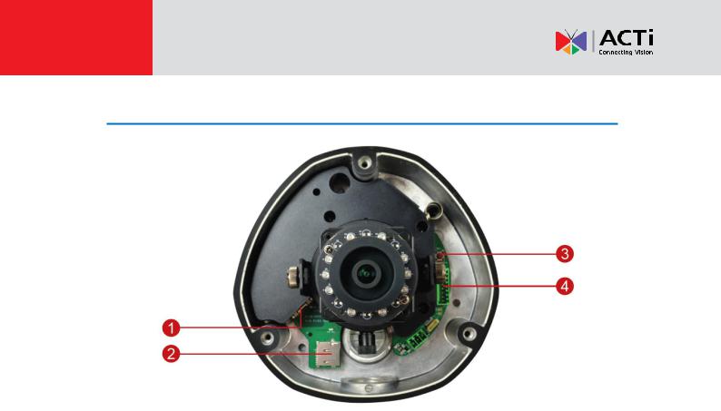
Physical Description
NOTE: The camera picture above is for reference only. Actual camera may slightly differ.
1)Ethernet Port
Connects to a network using an Ethernet cable.
2)Memory Card Slot
Insert a memory card (not included) into this slot for local recording purposes. See How to Install / Remove the Memory Card on page 37 for more information.
NOTE: Supports microSDHC and microSDXC cards.
3)Reset Button
The purpose of the reset button is to restore the factory default settings of the camera, including the administrator’s password.
When to use the reset button?
1.The administrator’s password has been forgotten and therefore the camera cannot be accessed.
2.In case of IP address, mask, or allow/deny filter related issues, resulting with inability to modify these settings.
3.In case of connectivity issues or abnormal video quality.
How to do the reset?
Press and hold the reset button for 5 seconds.
10 |
www.acti.com |
|
|
Hardware Manual
4)Digital Input / Output (DI/DO) and Audio Input / Output
This connector connects to digital input or output devices, such as an alarm trigger, panic button, etc., as well as audio input and output devices, such as microphones and speakers. Digital Input (DI) and Digital Output (DO) devices are used in applications like motion detection, event triggering, alarm notifications, etc. See Connecting DI/DO and Audio Devices (Optional) on page 29 for more information.
11 |
www.acti.com |
|
|
Hardware Manual
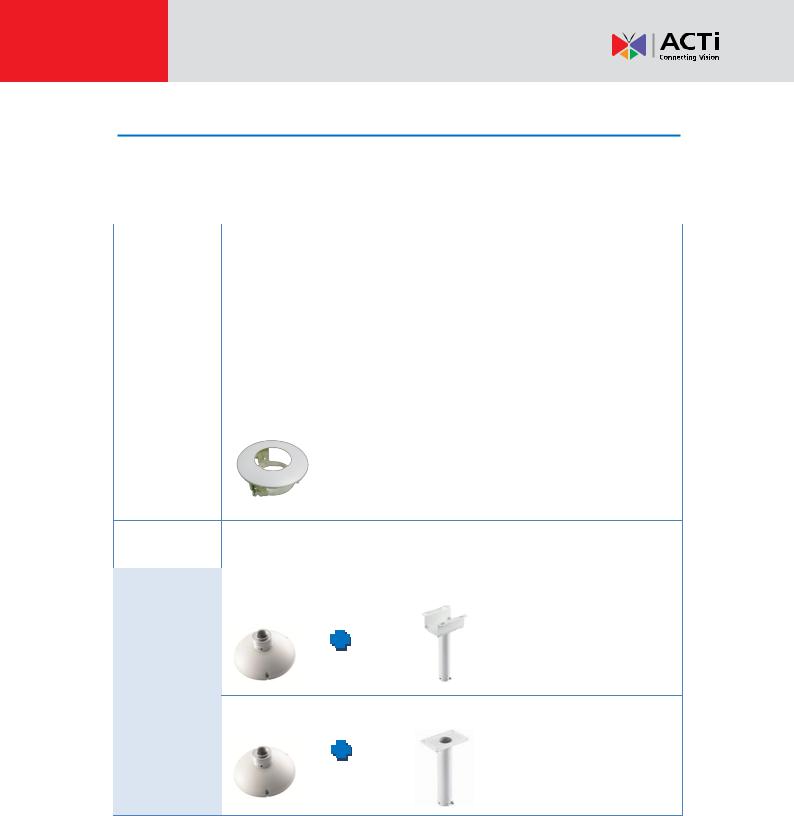
Mounting Options
There are several mounting options that you can use to install the camera. Select the most
suitable solution for your installation environment.
|
Mount Types |
|
|
|
Accessories |
|
|
|
|
|
|
|
|
|
|
|
Surface |
|
|
|
Suitable when mounting the camera directly walls or ceilings |
|
|
|
Mount |
|
|
|
without extra accessories. See Installing the Camera on a |
|
|
|
|
|
|
|
Surface on page 15 for mounting instructions. |
|
|
|
|
|
|
|
|
||
|
|
|
|
|
|
||
|
|
|
|
|
|
|
|
|
Flush Mount |
|
|
|
Suitable when mounting the camera discretely above dropped |
|
|
|
|
|
|
|
|
|
|
|
|
|
|
|
ceilings wherein only the dome cover will be visible underneath |
|
|
|
|
|
|
|
the ceiling. |
|
|
|
|
|
|
|
PMAX-1003 |
|
|
|
|
|
|
|
|
|
|
|
Pendant |
|
Suitable when mounting the camera on hard and high ceilings. |
|
|
Mount |
|
|
|
|
|
|
|
|
|
|
|
|
|
|
|
|
PMAX-0101 |
PMAX-0103 (Straight Tube with Bracket) |
PMAX-0101 |
PMAX-0102 (Straight Tube) |
12 |
www.acti.com |
|
|

Hardware Manual
Straight Wall Suitable when mounting the camera on straight walls.
Mount
PMAX-0308 (L-Type Wall Mount)
PMAX-0101 |
PMAX-0305 (Heavy Duty Wall Mount) |
Vertical Pole  Suitable when mounting the camera on vertical poles.
Mount |
PMAX-0101 |
PMAX-0305 |
PMAX-0503 |
|
|
|
|
|
|
|
|
Horizontal |
|
Suitable when mounting the camera on horizontal poles. |
||
|
Pole Mount |
|
|
|
|
|
|
|
|
|
|
|
|
|
|
|
|
|
|
|
PMAX-0101 |
PMAX-0102 |
PMAX-0503 |
|
|
|
|
|
|
|
|
Corner |
|
|
Suitable when mounting the camera on a corner wall. |
||
|
Mount |
|
|
|
|
|
|
|
|
|
|
|
|
|
|
|
|
PMAX-0101 |
PMAX-0305 |
PMAX-0402 |
|
|
|
|
|
|
|
|
|
|
|
|
|
|
13 |
www.acti.com |
|
|

Hardware Manual
Other Mounting Accessories
 Accessories
PMAX-0104 (Extension Tube) |
PMAX0700 (Junction Box) |
NOTE:
For more information about the mounting solutions and accessories, please check the
Mounting Accessory Selector in our website (http://www.acti.com/mountingselector).
The above mounting accessories are not included in the package. Contact your sales agents to purchase.
14 |
www.acti.com |
|
|
Hardware Manual
Installing the Camera on a Surface
This section describes the procedures in installing the camera on a flat surface such as a hard or dropped ceiling and straight or tilted walls. Before installation, make sure the wall or ceiling can bear more than the weight of the camera.
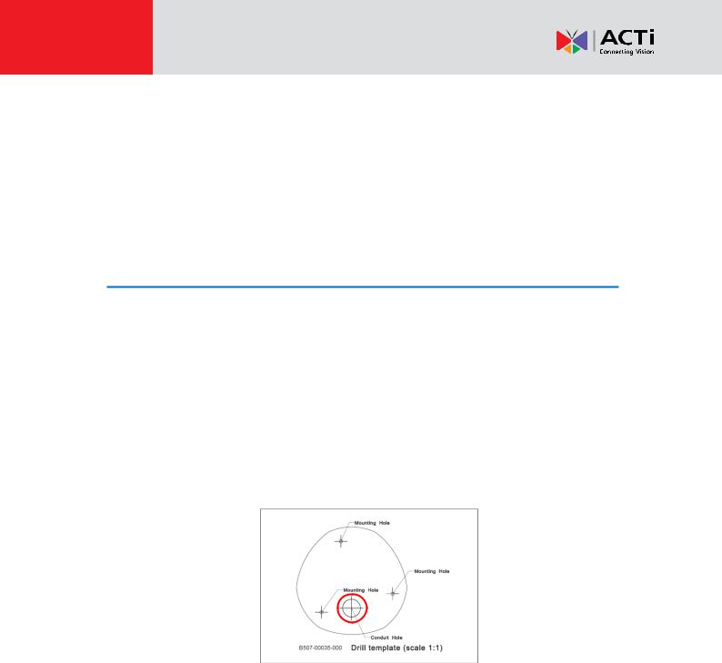
Step 1: Drill the Holes
Before drilling the holes, note the direction of the connectors side of the camera, which is also the opposite side of the camera logo. This influences the camera placement and where you should drill the hole where the cables will pass through or how the cables will go along the ceiling or wall.
1.According to the preferred camera orientation, mark the screw holes location on the surface.
2.Determine how the cables will be routed: pass through the surface or along the surface.
If the cables will pass through the surface, drill the cable hole and the three (3) screw holes on the surface.
If the cables will be routed along the surface, just drill the three (3) screw holes on the surface.
3.Insert the plastic plugs into the screw holes, if necessary.
15 |
www.acti.com |
|
|
 Loading...