


Bullet Camera Series
Hardware Manual
D41A, D42A, E42B, E43B, E47
Ver. 2014/05/05

Hardware Manual
Table of Contents |
|
Precautions |
4 |
Safety Instructions ........................................................................... |
6 |
Introduction |
7 |
List of Models.................................................................................... |
7 |
Package Contents............................................................................. |
8 |
Physical Description ........................................................................ |
9 |
Mounting Options ........................................................................... |
11 |
Installation Procedures Using the Bundled |
|
Bracket |
12 |
Step 1: Install the Bundled Bracket............................................... |
12 |
Step 2: Attach the Sunshield ......................................................... |
13 |
Step 3: Install the Camera .............................................................. |
14 |
Step 4: Waterproof and Connect the Cable .................................. |
15 |
How to Use the Cable Gland........................................................ |
16 |
How to Use the Conduit Gland..................................................... |
19 |
Step 5: Connect the Cable ............................................................. |
23 |
Step 6: Access the Camera Live View........................................... |
23 |
Other Connections |
24 |
How to Connect DI/DO Devices (Optional) ................................... |
24 |
How to Connect Audio Input / Output Devices (Optional)........... |
27 |
Adjustments and Accessories |
28 |
How to Install / Remove the Memory Card ................................... |
28 |
How to Insert the Memory Card ................................................... |
28 |
How to Remove the Memory Card ............................................... |
29 |
Adjust the Viewing Angle and Focus ............................................ |
30 |
How to Reset the Camera............................................................... |
31 |
2 |
www.acti.com |
|
|

Hardware Manual
Accessing the Camera |
32 |
Configure the IP Addresses ........................................................... |
32 |
Using DHCP Server to Assign IP Addresses................................ |
32 |
Using the Default Camera IP Address.......................................... |
34 |
Access the Camera......................................................................... |
36 |
3 |
www.acti.com |
|
|

Hardware Manual
Precautions
Read these instructions
You should read all the safety and operating instructions before using this product.
Heed all warnings
You must adhere to all the warnings on the product and in the instruction manual. Failure to follow the safety instruction given may directly endanger people, cause damage to the system or to other equipment.
Servicing
Do not attempt to service this video device yourself as opening or removing covers may expose you to dangerous voltage or other hazards. Refer all servicing to qualified service personnel.
Trademarks
All names used in this manual are probably registered trademarks of respective companies.
Liability
Every reasonable care has been taken during the writing of this manual. Please inform your
local office if you find any inaccuracies or omissions. We cannot be held responsible for any
typographical or technical errors and reserve the right to make changes to the product and
manuals without prior notice.
4 |
www.acti.com |
|
|

Hardware Manual
Federal Communications Commission Statement
This equipment has been tested and found to comply with the limits for a class B digital device, pursuant to Part 15 of the FCC Rules. These limits are designed to provide reasonable protection against harmful interference in a
residential installation. This equipment generates, uses, and can radiate radio frequency energy and, if not installed and used in accordance with the instructions, may cause harmful interference to radio communications. However, there is no guarantee that interference will not occur in a particular installation. If this equipment does cause harmful interference to radio or television reception, which can be determined by turning the equipment off and on, the user is encouraged to try to correct the interference by one or more of the following measures:
Reorient or relocate the receiving antenna.
Increase the separation between the equipment and receiver.
Connect the equipment into an outlet on a circuit different from that to which the receiver is connected.
Consult the dealer or an experienced radio/TV technician for help.
Warning: Changes or modifications to the equipment that are not expressly approved by the responsible party for compliance could void the user’sauthority to operate the equipment.
European Community Compliance Statement
This product has been tested and found to comply with the limits for Class B
Information Technology Equipment according to European Standard EN 55022
and EN 55024. In a domestic environment, this product may cause radio interference in which cause the user may be required to take adequate measures.
5 |
www.acti.com |
|
|

Hardware Manual
Safety Instructions
Don’t open the housing of the product
Cleaning
Disconnect this video product from the power supply before cleaning.
Attachments
Do not use attachments not recommended by the video product manufacturer as they may cause hazards.
Water and Moisture
Do not use this video product near water, for example, near a bathtub, washbowl, kitchen sink, or laundry tub, in a wet basement, or near a swimming pool and the like.
Don’t use accessories not recommended by the manufacturer
Only install this device in a dry place protected from weather
Servicing
Do not attempt to service this video product yourself as opening or removing covers may expose you to dangerous voltage or other hazards. Refer all servicing to qualified service personnel.
Damage Requiring service
Disconnect this video product from the power supply immediately and refer servicing to qualified service personnel under the following conditions.
1)When the power-supply cord or plug is damaged
2)If liquid has been spilled, or objects have fallen into the video product.
3)If the video product has been directly exposed to rain or water.
4)If the video product does not operate normally by following the operating Instructions in this manual. Adjust only those controls that are covered by the instruction manual, as an improper adjustment of other controls may result in damage, and will often require extensive work by a qualified technician to restore the video product to its normal operation.
Safety Check
Upon completion of any service or repairs to this video product, ask the service technician to perform safety checks to determine if the video product is in proper operating condition.
6 |
www.acti.com |
|
|
Hardware Manual
Introduction
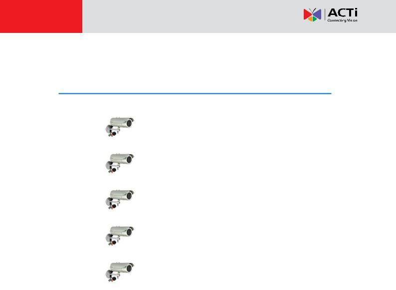
List of Models
This hardware manual contains the following models:
D41A |
|
1MP Bullet with D/N, Adaptive IR, Vari-focal lens |
|
|
|
D42A |
|
3MP Bullet with D/N, Adaptive IR, Vari-focal lens |
|
|
|
E42B |
|
3MP Bullet with D/N, Adaptive IR, Basic WDR, Vari-focal lens |
|
|
|
E43B |
|
5MP Bullet with D/N, Adaptive IR, Basic WDR, Vari-focal lens |
|
|
|
E47 |
|
1.3MP Bullet with D/N, Adaptive IR, Basic WDR, SLLS, |
|
Vari-focal lens |
|
|
|
|
|
|
|
7 |
www.acti.com |
|
|

Hardware Manual
Package Contents
|
Camera |
|
|
|
Conduit Gland |
|
Cable Gland |
|
|
|
|
|
|
|
|
|
|||
|
|
|
|
|
|
|
|
|
|
|
|
|
|
|
|
|
|||
|
|
|
|
|
|
|
|||
|
Washer |
|
|
|
Mounting Screw Kit |
|
Sunshield Screw Kit |
|
|
|
|
|
|
|
|
|
|||
|
|
|
|
|
|
|
|||
|
|
|
|
|
|
|
|||
|
Bracket |
|
|
|
Bracket Plate |
|
Sunshield |
|
|
|
|
|
|
|
|
|
|
||
|
|
|
|
|
|
|
|
||
|
|
|
|
|
|
|
|
||
|
Warranty Card |
|
|
|
Quick Installation Guide |
|
|
|
|
|
|
|
|
|
|
|
|
|
|
|
|
|
|
|
|
|
|
|
|
|
|
|
|
|
|
|
|
|
|
|
|
8 |
|
www.acti.com |
|||||
|
|
|
|
|
|
|
|
Hardware Manual
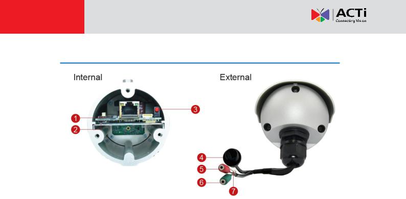
Physical Description
|
Item |
Description |
|
|
|
1 |
Memory Card Slot |
Insert a memory card (not included) into this slot for local |
|
|
recording purposes. See How to Install / Remove the Memory |
|
|
Card on page 28 for more information. |
|
|
NOTE: Supports microSDHC and microSDXC cards. |
|
|
|
2 |
Reset Button |
Use the Reset Button to reset the camera to its factory default |
|
|
settings. To do the reset, press and hold the Reset button for at |
|
|
least 5 seconds or until the Power LED lights up. When the |
|
|
Power LED lights up again, reset is complete. See How to Reset |
|
|
the Camera on page 31. |
|
|
|
3 |
Power LED |
The Power LED lights up when the camera is connected to the |
|
|
power source and goes off once the camera boot-up process is |
|
|
complete. |
|
|
NOTE: For typical use, the power LED is hidden inside the |
|
|
housing and cannot be seen. However, knowing how the power |
|
|
LED works is essential when troubleshooting or doing a reset. |
|
|
|
4 |
Ethernet Port |
Connects to a network using a standard Ethernet cable. |
|
|
|
5 |
Audio Input |
Connects to audio input devices, such as a microphone with |
|
|
built-in amplifier, etc. |
|
|
NOTE: The microphone must have a built-in amplifier. |
|
|
Connecting an ordinary microphone will dwarf sounds and will |
|
|
result in inaudible recording. |
|
|
|
6 |
Audio Output |
Connects to audio output devices, such as a speaker, etc. |
|
|
|
9 |
www.acti.com |
|
|

Hardware Manual
|
Item |
Description |
|
|
|
7 |
Digital Input / Output |
Connects to digital input or output devices, such as an alarm |
|
|
trigger, panic button, etc. Digital Input (DI) and Digital Output |
|
|
(DO) devices are used in applications like motion detection, |
|
|
event triggering, alarm notifications, etc. See How to Connect |
|
|
DI/DO Devices (Optional) on page 24 for information on how to |
|
|
connect DI/DO devices to your camera. |
|
|
|
10 |
www.acti.com |
|
|
Hardware Manual
Mounting Options
In areas with fierce weather conditions, the light bundled bracket can be replaced by a heavy duty outdoor bracket combined with additional mounting accessories.
Below are the optional mounting accessories that you can use with the camera.
|
Mount Types |
|
|
Accessories |
|
|
|
|
|
||
|
|
|
|
|
|
Corner Mount |
|
|
Suitable when mounting the camera on a corner wall. |
||
|
|
|
|
|
|
|
|
|
|
PMAX-1103 |
PMAX-0402 |
+
Pole Mount |
Suitable when mounting the camera on a pole. |
|
|
|
|
|
PMAX-1103 |
PMAX-0503 |
+
NOTE:
For more information about the mounting solutions and accessories, please check the
Mounting Accessory Selector in our website (http://www.acti.com/mountingselector).
The above mounting accessories are not included in the package. Contact your sales agents to purchase.
11 |
www.acti.com |
|
|
Hardware Manual
Installation Procedures Using the
Bundled Bracket
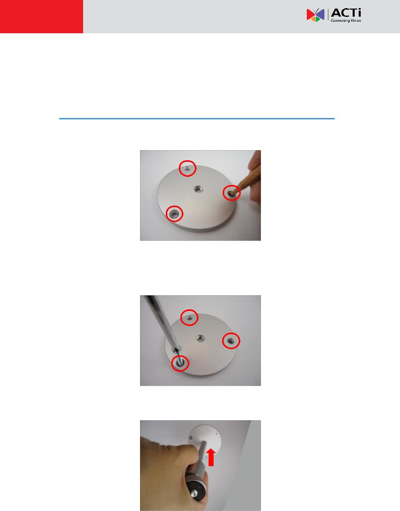
Step 1: Install the Bundled Bracket
1.Mark the location of the three (3) screw holes using the bracket plate included in the package.
NOTE: Depending on the surface where you will install the camera, it may be necessary to drill the holes and use the supplied screw tox.
2. Attach the plate to the surface using the three (3) supplied screws.
3. Attach the bracket to the plate.
12 |
www.acti.com |
|
|
 Loading...