

Acer AL506, AL506SG Schematic

ACER Monitor AL506
- Table of Contents -
1. Attention During Servicing ...........................................................................................................................2
2. Monitor Appearance Description of ProLite E380S .....................................................................................3
2-1. Front View .........................................................................................................................................3
2-2. Rear View...........................................................................................................................................4
2-3. System Block Diagram ......................................................................................................................5
2-4. Explosion Diagram ............................................................................................................................6
3. OSD Menu Screen.........................................................................................................................................8
4. Description of Level 1 Service Tools..........................................................................................................13
5. Troubleshooting Analysis............................................................................................................................14
6. Level 1 Service Items--Monitor Assembly and Disassembly ............................................................................................19
6-1. Remove Stand Bottom .....................................................................................................................20
6-2. Separate Cover (Case Rear Assy) ....................................................................................................20
6-3. Remove FFC ....................................................................................................................................22
6-4. Remove Bezel ..................................................................................................................................22
6-5. Remove lnverter...............................................................................................................................23
6-6. Change New Inverter .......................................................................................................................26
6-7. Remove AD PCBA ..........................................................................................................................29
6-8. Change New AD PCBA...................................................................................................................32
6-9. Change New SW/B (PCB-K)...........................................................................................................35
6-10. Change New SW/B(PCB-K)..........................................................................................................36
6-11. Case Assembly...............................................................................................................................37
7.FRU ..............................................................................................................................................................41
8. Method for LCD Monitor Testing after Servicing ......................................................................................43
8-1. Test Method Without Connection of Computer ...............................................................................43
8-2. Test Method with Connection of Computer.....................................................................................44
8-3. Definition of the Connector Pin of Signal Cable.............................................................................44
8-4. Specification ....................................................................................................................................45
8-5. Factory Mode Function....................................................................................................................47
9.BIOS & OSD Software Update....................................................................................................................48
9-1. Programs: .........................................................................................................................................48
9-2. Tools.................................................................................................................................................48
9-3. Install BIOS Software (Simply way to ROM) & kit: ......................................................................48
9-4. Program Running .............................................................................................................................50
10. Glossary.....................................................................................................................................................54

ACER Monitor AL506
1. Attention During Servicing
1-1. This monitor should be operated from the type of power indicated on the using
label. If you are not sure of the type of power available, consult your dealer or
local power company..
1-2. The LCD shall be placed at low humidity and low dust.
1-3. Place the LCD on firm flat surface carefully. The surface of the LCD monitor is
plastic material and thin glass, drop or sharp impact will cause damage to the
LCD monitor.
1-4. Do not use alcohol or ammonia-based liquid to clean the monitor. If necessary,
clean with a slightly damp cloth. Disconnect the monitor from the power
supply before cleaning.
1-5. Remove the power supply immediately in case of abnormality occurred in the
LCD, especially strange noise of smell
1-6. Turn on power for testing only after complete the assembly of the monitor
include casing and tighten the screw while servicing the monitor to prevent
hazard.
ACER Monitor AL506
2. Monitor Appearance Description
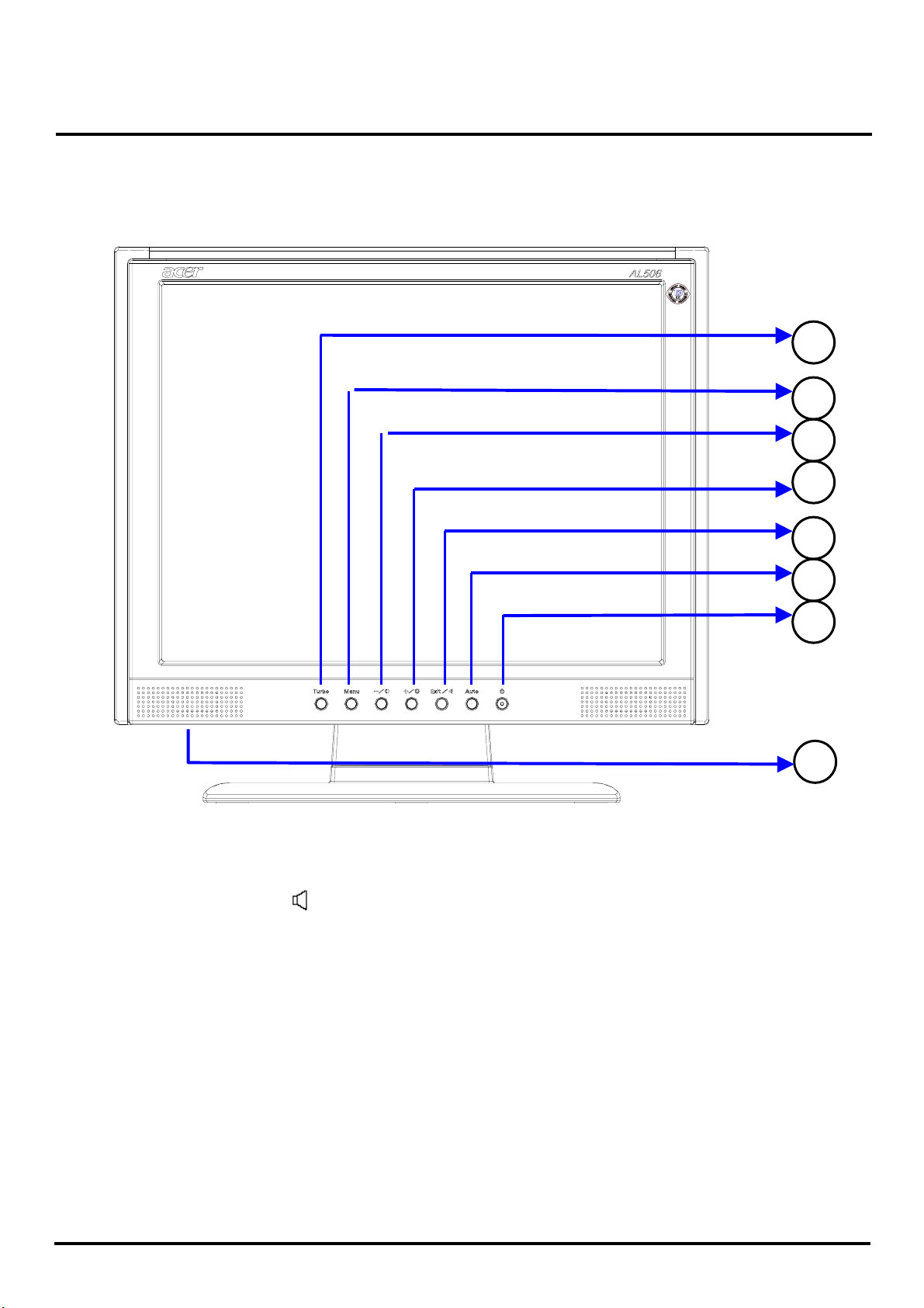
2-1. Front View
Turbo
1
Menu - / Contrast
2
3
Button (Exit / )
+ / Brightness
4
Exit / Volume
5
Auto : Auto Setup
6
Power Switch /Power Indicator
7
Green : Normal
Blue
Orange : Power Off
8
Speakers
: Power Saving
ACER Monitor AL506
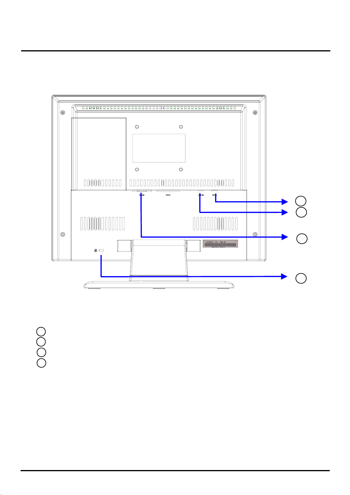
2-2. Rear View
10
11
12
13
DC Power Jack (DC-In)
10
Stereo Mini Jack (LINE-IN)
11
D-sub mini 15pin Connector (D-SUB)
12
Lock hole
13
ACER Monitor AL506
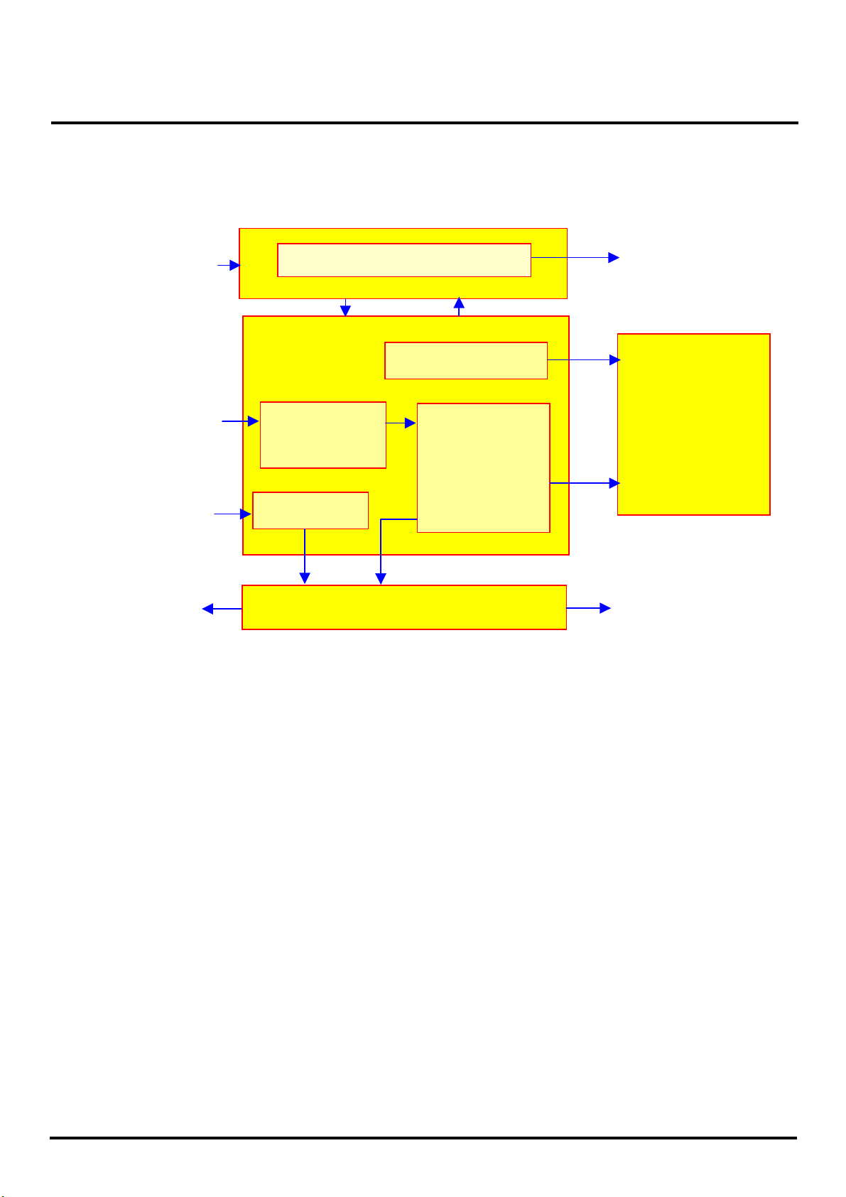
2-3. System Block Diagram
Adapter IN
(+12VDC) Power
Inverter
Lamp X3
DC-DC converter
Analog IN
Audio IN
A/D
converter
Audio Amp
LCD controller
-Scaler
-OSD
-T-con
LCD panel
Speaker
OSD Keypad
Speaker
ACER Monitor AL506
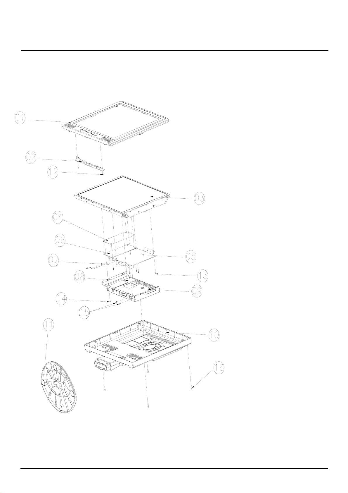
2-4. Explosion Diagram
1.BEZEL_W/_SPEAKER_
CIRCLE_ASSY
2.OSD PCBA
3.PANEL ASSY
4.PET_FILM_METAL_
FRAM_REAR
5.SMART PCBA
6.INVERTER
7.FFC AD_OSD
8.PET ISOLUTION FILM
9.METAL COVER SMART
10.REAR_STAND_
11.SEAT_ELLIPSE_ASSY
W/O_TUNER_ASSY
12.SCREW
13. SCREW
14. SCREW
15.STAND-OFF
16.SCREW
ACER Monitor AL506
The Table of Explosion Diagram
NUM. ITEM NAME CHI-MEI P/N
1
2
3
4
5
6
7
9
10
11
12
BEZEL_W/_SPEAKER_CIRCLE_ASSY
OSD PCBA
PANEL ASSY
PET_FILM_METAL_FRAM_REAR
SMART PCBA
INVERTER
FFC AD_OSD
METAL COVER SMART
REAR_STAND_W/O_TUNER_ASSY
SEAT_ELLIPSE_ASSY
SCREW
40A1522923
35A15K0208
44A1513026
7341391001
35A15S0203
2714000001
3241500001
41A1599115
40A1592966
40A1592949
42A9930001
13
14
15
16
SCREW
SCREW
STAND-OFF
SCREW
42A9920002
42A9930008
42A9940007
42A9930009
ACER Monitor AL506
A
play
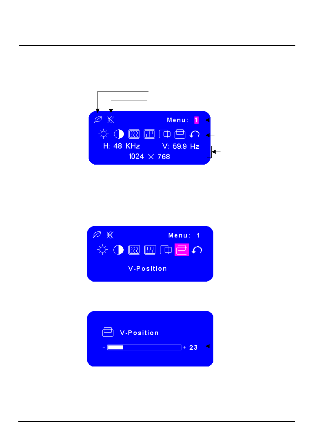
3. OSD Menu Screen
Operate
Explanation
Press the Menu Button to start the On Screen Display feature. There are additional
Menu pages which can be switched by using the +/–Buttons.
ed while Turbo is active
V-Position
Dis
Displayed while Mute is active
50
Page no.
djustment icon
Current horizontal frequency,
vertical refresh rate and
resolution
Select the Menu page that contains the adjustment icon relating to the adjustment
you want to make. Press the Menu Button again. Then, use the +/– Buttons to
highlight the desired adjustment icon. Press the Menu Button again.
Use the +/–Buttons to make the appropriate adjustment or setting.
For example, to correct for vertical position, select Menu page number 1 and then
press the Menu Button. Then, select (V-Position) by using the +/– Buttons.
An adjustment scale appears after you press the Menu Button. Use the +/– Buttons
to change the vertical position settings. The vertical position of the overall display
should be changing accordingly while you are doing this.
The bar shows the progress of the
adjustment being made
ACER Monitor AL506
g
Notes
Adjust
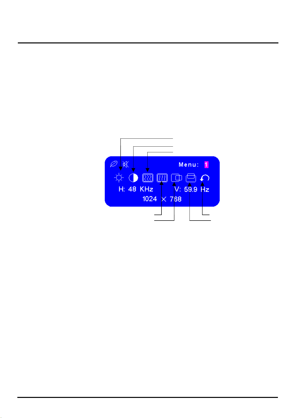
Menu contents
Menu: 1
The On Screen Display disappears several seconds after you stop pressing the
buttons while performing an adjustment.
Any changes are automatically saved in the memory when the On Screen Display
disappears. Turning off the power should be avoided while using the Menu.
Adjustments for Clock, Phase and Position are saved for each signal timing. Except
for these adjustments, all other adjustments have only one setting which applies to
all signal timings.
Pressing [+] , [-] or [Menu] buttons for the adjustment when the OSD is executed.
htness*1 (Direct)
Bri
Contrast (Direct)
Clock
Phase
H-Position
*1 Adjust the Brightness when you are using the monitor in a dark room and feel the
screen is too bright.
Note:
SWITCHING BRIGHTNESS /CONTRAST ADJUSTMENT:
To switch between Brightness and Contrast adjustments, press the Menu Button within 10
seconds after pressing the Brightness Button or the Contrast Button during the direct
adjustments above.
Return to Menu
V-Position
ACER Monitor AL506
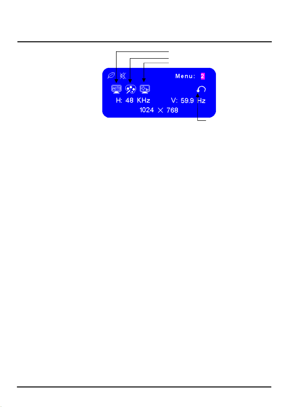
A
Menu: 2
uto Set-up*1 (Direct)
Color Temp.
Sharpness
*1 For best results, use the Auto Set-up in conjunction with the adjustment pattern. And
the screen becomes dark for approximately five seconds during the adjustment.
Note:
Auto Set-up Setting:
No: The Auto Set-up is not performed when the signal input is changed.
Yes: Adjust Clock and Phase automatically when the signal input is changed.
Color Temp.: Color 1: 9300K; Color 2: 7500K; Color 3: 6500K; sRGB: User
Return to Menu
sRGB is an international standard which defines and unifies the difference of
color appearance between equipment.
Sharpness: Adjust the picture quality at resolutions of less than 1024 × 768. You
can change the picture quality from 1 to 5 (sharp to soft). Press the + Button to
change the picture quality in numerical order. Press the – Button to change the
picture quality in reverse numerical order.

ACER Monitor AL506
(
)
Menu: 3
Volume
OSD Position
Language
Note:
OSD Position: You can move the OSD display area to any one of the following
5 positions within the overall display:
1
4
3
2
Press the + Button to move the OSD in numerical order. Press the – Button to move
the OSD in reverse numerical order.
5
Direct
Return to Menu
Reset
Language: Eng: English; Dth: German; Fns: French; Ity: Italian; Epl: Spanish;
Jpn: Japanese; T-C: Tranditional Chinese; S-C: Simplified Chines

ACER Monitor AL506
Direct
You can skip the Menu pages and display an adjustment scale directly by using the
following button operations:
Brightness: Press the Brightness Button when the Menu is not displayed.
Contrast: Press the Contrast Button when the Menu is not displayed.
Auto Set-up: Press the Auto Button when the Menu is not displayed.
Volume: Press the Volume Button when the Menu is not displayed. When OSD
menu is off, holding this button for 1-2 seconds will switch the Mute function
between ON and OFF.
Turbo:
Pct: Picture Mode (High brightness)
Text: Text Mode (Normal)
Eco Economy (Brightness of back-light is reduced)
Changing to a lower brightness mode can lessen eye fatigue.
Change from Picture Mode to Text Mode when working with text.
Change from Text Mode to Economy Modes when viewing the screen for long
periods.
ACER Monitor AL506
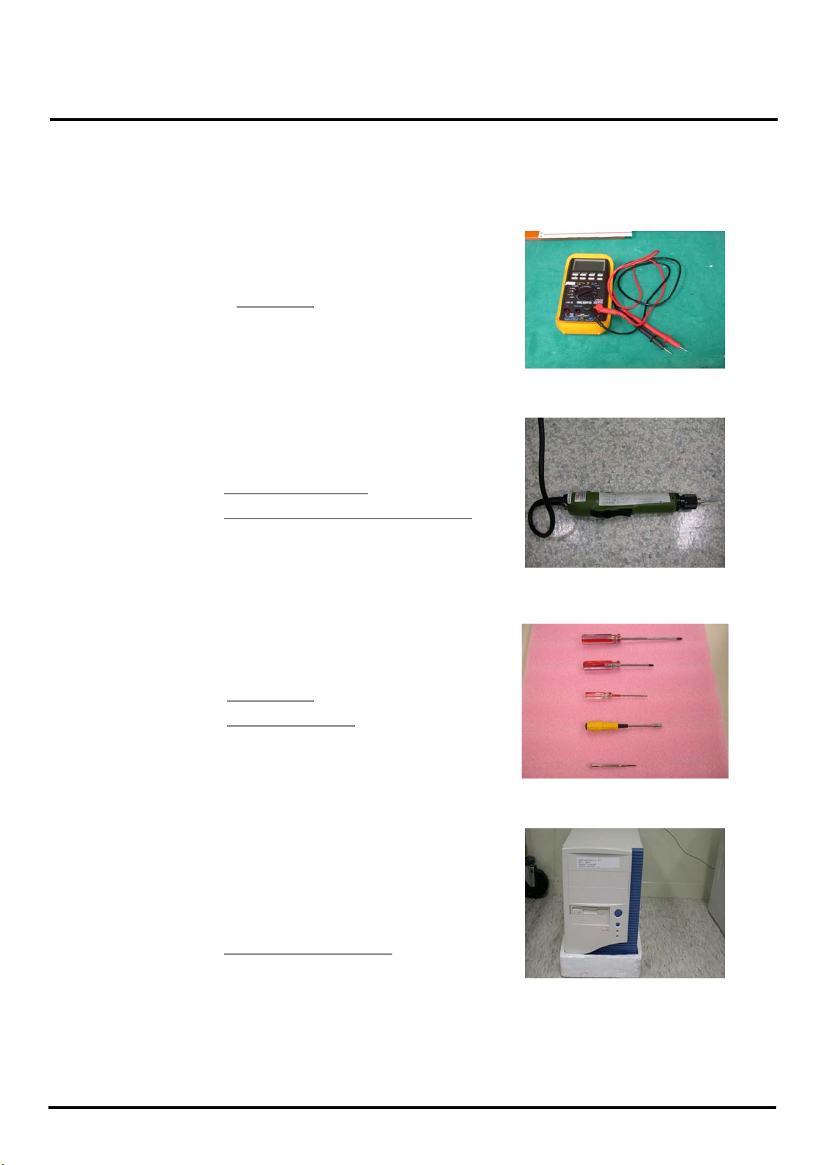
4. Description of Level 1 Service Tools
Definition : Replacement of failed PCB and internal signal wire.
Tools :
1. Multimeter.
Multimeter
2. Electric screwdriver.
Electric screwdriver
Torque value: adjust to 1.5kgf*cm
3. Screwdrivers
Screwdriver
Hexagon Wrench
Testing equipment : PC
Computer for testing :
ACER Monitor AL506
N
N
p
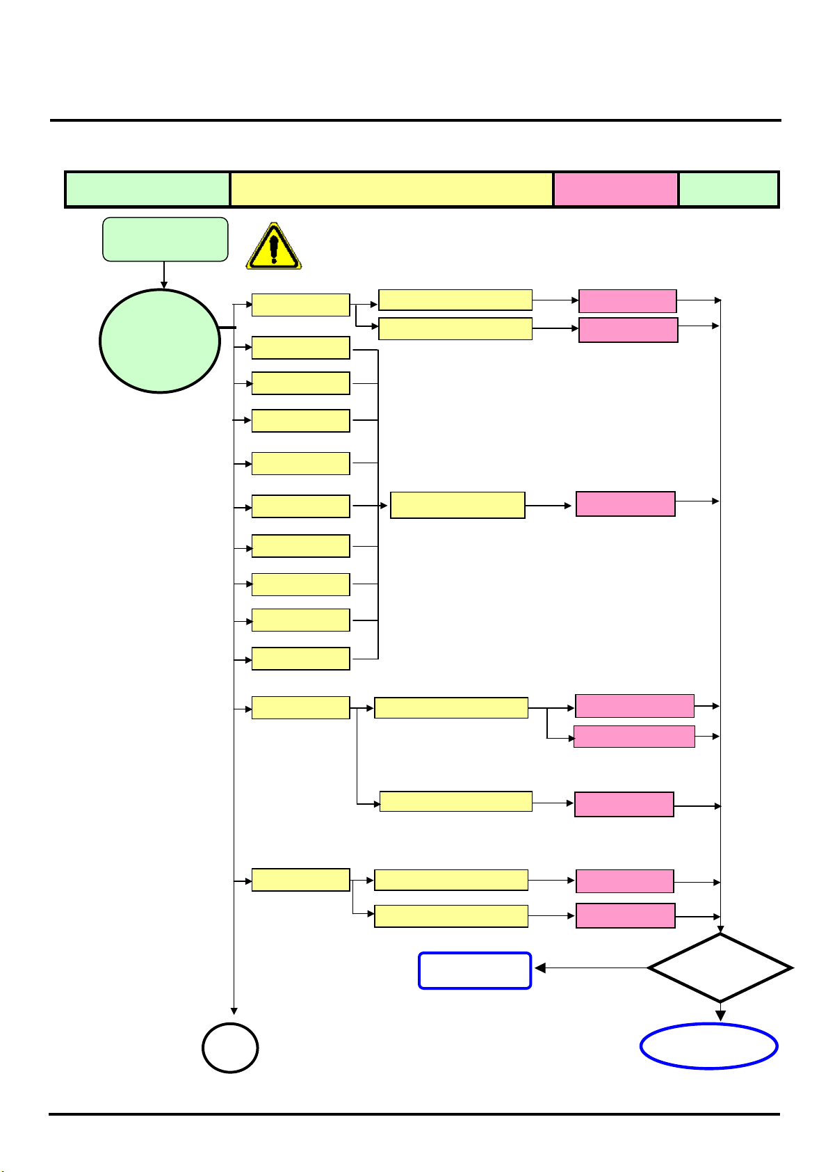
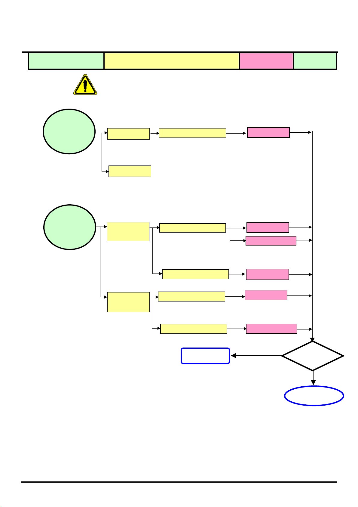
5. Troubleshooting Analysis
Defect Mode Failure Analysis Repair Testing
Light On Test
※ “ Panel Change” Should be Performed to Level 3 Repair stage
Abnormal
Display
Missing Line
Bright Dot
Dark Dot
Backlight
Light Leakage
Mura
Check PCB
Check Panel
Check Panel
AD/B Change
Panel Change
Panel Change
Image Sticking
Brightness spot
Particle
Dot Defect
o display
Check PCB
AD/B Change
Inverter Change
Check Panel
Panel Change
oise
Check PCB
AD/B Change
Check Panel
Next Ste
Panel Change
NG
TEST
Completed
A
ACER Monitor AL506
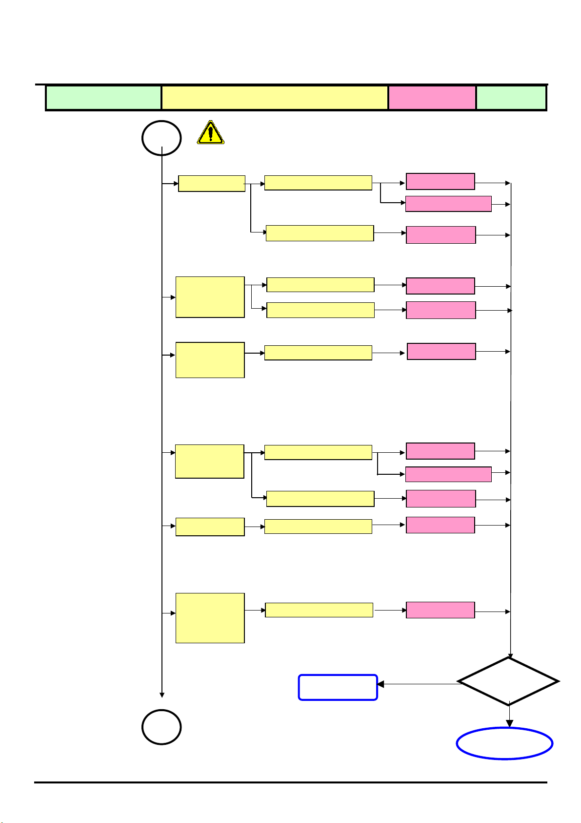
N
p
Defect Mode Failure Analysis Repair Testing
A
※ “ Panel Change” Should be Performed to Level 3 Repair stage
Flicker
Check PCB
Check OSD
AD/B Change
Inverter Change
Adjust VCOM
Gray value
display
Check PCB
Check Panel
AD/B Change
Panel Change
R.G.B display
abnormal
Check PCB
AD/B Change
Display Shut
Down
Check PCB
AD/B Change
Inverter Change
o signal
Check Panel
Check PCB
Panel Change
AD/B Change
Power on
Display
abnormal
Check PCB
AD/B Change
Next Ste
NG
TEST
A
Completed
ACER Monitor AL506
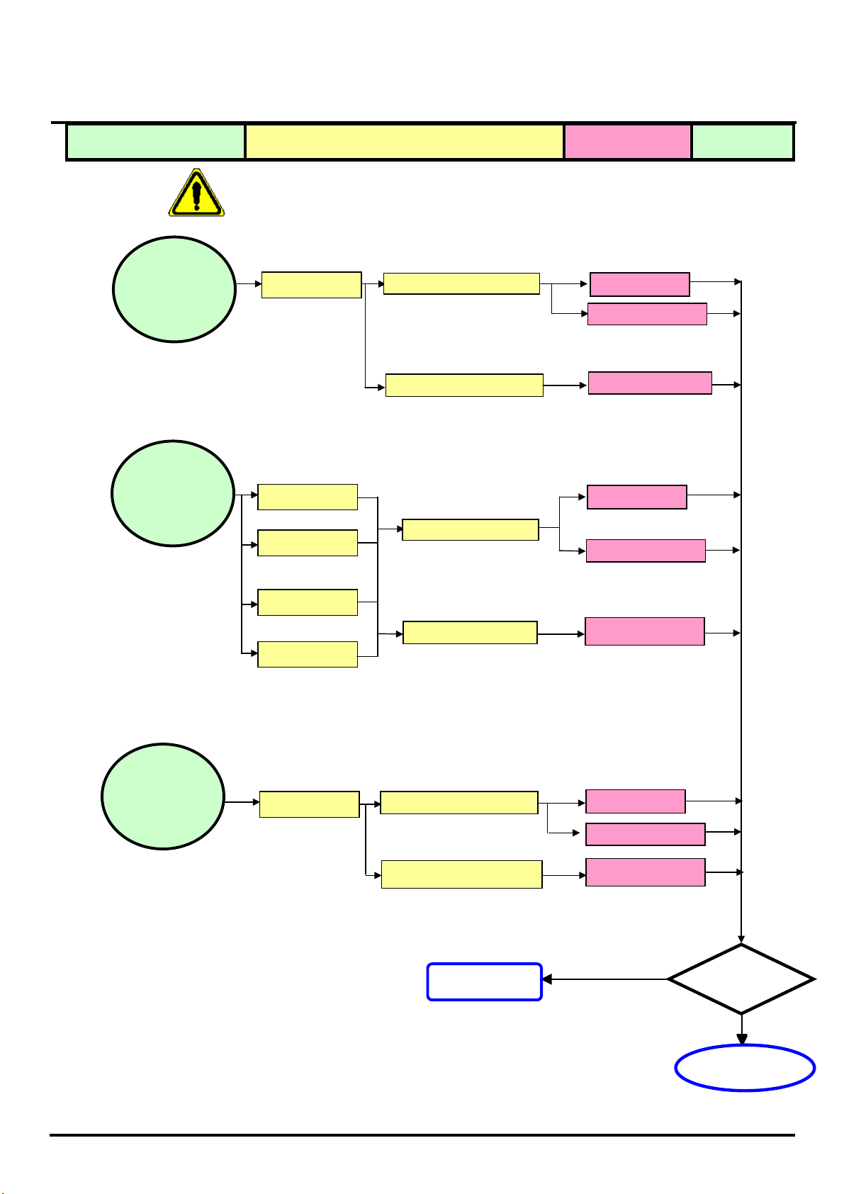
N
r
p
r
Defect Mode Failure Analysis Repair Testing
※ “ Panel Change” Should be Performed to Level 3 Repair stage
ON/OF
Abnormal
o Powe
Check PCB
AD/B Change
SW/B Change
Check Wire
FFC Change
LED display
abnormal
LED Off
LED Dark
AD/B Change
Check PCB
SW/B Change
LED Abnormal
LED Flicke
Check Wire
FFC Change
Abnormal
Keyboard
Unavailable
Check PCB
Check Wire
AD/B Change
SW/B Change
FFC Change
Next Ste
NG
TEST
Completed
ACER Monitor AL506
p
Defect Mode Failure Analysis Repair Testing
Abnormal BIOS
&OSD
※ “ Panel Change” Should be Performed at Level 3 Repair stage
Can’t Input
Can’t Read
Check PCB
AD/B Change
Other Abnormal
Display
Display Shut
Down
Display flicker
(tapping )
Check PCB
Check Panel
Check PCB
AD/B Change
Inverter Change
Panel Change
AD/B Change
Check Panel
Inverter Change
Next Ste
NG
TEST
Completed
 Loading...