

Page 1

AN7
Socket 462 System Board
User’s Manual
4200-0390-02
Rev. 1.00
Page 2

Copyright and Warranty Notice
The information in this document is subject to change without notice and does not
represent a commitment on part of the vendor, who assumes no liability or
responsibility for any errors that may appear in this manual.
No warranty or representation, either expressed or implied, is made with respect to the
quality, accuracy or fitness for any particular part of this document. In no event shall
the manufacturer be liable for direct, indirect, special, incidental or consequential
damages arising from any defect or error in this manual or product.
Product names appearing in this manual are for identification purpose only and
trademarks and product names or brand names appearing in this document are the
property of their respective owners.
This document contains materials protected under International Copyright Laws. All
rights reserved. No part of this manual may be reproduced, transmitted or transcribed
without the expressed written permission of the manufacturer and authors of this
manual.
If you do not properly set the motherboard settings, causing the motherboard to
malfunction or fail, we cannot guarantee any responsibility.
AN7
Page 3

Table Of Contents
AN7 快速安裝指引 ................................................................................... 2
AN7 のクイックインストールガイド ................................................... 4
AN7 Schnellinstallationsanleitung .......................................................... 6
AN7 Guide d’Installation Rapide ........................................................... 8
Краткое руководство по установке AN7........................................... 10
Guida all’installazione veloce Scheda madre AN7 .............................. 12
Chapter 1. Introduction .......................................................................... 1-1
1-1. Features & Specifications ........................................................................1-1
1-2. Layout Diagram .......................................................................................1-3
Chapter 2. Hardware Setup.................................................................... 2-1
2-1. Install The Motherboard...........................................................................2-1
2-2. Install CPU and Heatsink.........................................................................2-1
2-3. Install System Memory ............................................................................2-3
2-4. Connectors, Headers and Switches ..........................................................2-4
(1). ATX Power Input Connectors........................................................2-4
(2). FAN Connectors.............................................................................2-5
(3). CMOS Memory Clearing Header .................................................. 2-6
(4). Wake-up Header............................................................................. 2-7
(5). Front Panel Switches & Indicators Headers ..................................2-8
(6). Additional USB Port Header .........................................................2-9
(7). Additional IEEE1394 Port Header...............................................2-10
(8). Front Panel Audio Connection Header ........................................ 2-11
(9). Internal Audio Connectors ...........................................................2-12
(10). Accelerated Graphics Port Slot....................................................2-13
(11). Floppy Disk Drive Connector......................................................2-14
(12). IDE Connectors............................................................................2-15
(13). Serial ATA Connectors .................................................................2-16
(14). Status Indicators ...........................................................................2-17
(15). System Management Bus Headers...............................................2-18
(16). POST Code Display .....................................................................2-19
(17). Back Panel Connectors ................................................................2-20
User’s Manual
Page 4

Chapter 3. BIOS Setup............................................................................ 3-1
3-1. SoftMenu Setup........................................................................................3-3
3-2. Standard CMOS Features.........................................................................3-5
3-3. Advanced BIOS Features......................................................................... 3-8
3-4. Advanced Chipset Features....................................................................3-10
3-5. Integrated Peripherals ............................................................................3-12
3-6. Power Management Setup .....................................................................3-16
3-7. PnP/PCI Configurations.........................................................................3-18
3-8. PC Health Status ....................................................................................3-20
3-9. Load Fail-Safe Defaults .........................................................................3-23
3-10. Load Optimized Defaults.......................................................................3-23
3-11. Set Password ..........................................................................................3-23
3-12. Save & Exit Setup..................................................................................3-23
3-13. Exit Without Saving...............................................................................3-23
Appendix A. Install NVIDIA nForce Chipset Driver .......................................... A-1
Appendix B. Install Serial ATA RAID Driver...................................................... B-1
Appendix C. Install ABIT µGuru Driver..............................................................C-1
Appendix D. POST Code Definition ..................................................................... D-1
Appendix E. Troubleshooting (Need Assistance?)...............................................E-1
Appendix F. How to Get Technical Support........................................................ F-1
AN7
Page 5

1
User’s Manual
Page 6
2 AN7 快速安裝指引
AN7 快速安裝指引
如您要瞭解此主機板更詳細的資訊,請參閱我們的完整版使用手冊,裡面會有詳盡的說明。此快速
安裝手冊是給有經驗的系統組裝者使用,如果這是您第一次嘗試來組裝您的電腦系統,我們建議您
先去閱讀完整版的使用手冊,或是詢問技術人員來幫助您組裝您的電腦系統。(完整版的使用手冊
已包覆在隨本主機板所附的驅動程式與應用光碟之中。)
處理器的安裝
本主機板提供零出力(Zero Insertion Force, ZIF)
式 Socket 462,以方便安裝 AMD Socket A。您所
購買的 CPU 應已配備一組散熱套件及散熱片,如
果沒有,請另行購買專為 Socket A 設計的散熱套
件及散熱片。
請參考這裡所表示的圖來安裝 CPU 中央處理器和
散熱器。(僅供參考。您的散熱器與風扇組合可
能不見得與這一個完全相同。)
1. 請找出這塊主機板的 Socket 462 位置。將 CPU
插座桿拉出至插座旁,然後將插座桿以 90 度
角向上拉。
2. 將 CPU 的缺角對準 CPU 插座的缺角,CPU
插腳的一端向下置 CPU 插座。因為只能朝著
一個固定的方向插入 CPU,如果遇到阻礙
時,切勿勉強用力。最後壓住 CPU,拴上插
座桿。
3. 請將散熱器底面的自黏膠模移除,散熱器底
部凹角一端面向 CPU 插座標示 “Socket 462”
的一方,散熱器面向下蓋住 CPU,直到完全
蓋住 CPU 為止。
4. 先將固定夾具短的一邊壓下扣住 CPU 插座底
端的中間鎖扣。
5. 再以螺絲起子插入固定夾具長的一邊的凹
槽,壓下扣住 CPU 插座底端的中間鎖扣。現
在散熱器與風扇組合已互相緊扣在 CPU 插座
上。
6. 將散熱器與風扇組合的風扇電源端子與主機
板上面的風扇電源端子連接。
注意:請不要忘記去設定處理器正確的匯流排頻
率和倍頻的數值。
AN7
Page 7
AN7 快速安裝指引 3
將主機板安裝到機殼上
當您將處理器安裝到主機板上之後,您便可以開始將主機板固定到電腦機殼裡去。首先;請您先將
主機板固定到電腦機殼。大多數的電腦機殼底座都有許多的固定孔位,請將主機板上的固定孔位與
機殼底座上的固定孔位對準。如果孔能對準並且有螺絲孔,就表示可使用銅柱來固定主機板。另外;
您可以使用塑膠墊片來讓螺絲與主機板的 PCB 表層隔離(絕緣)。
安裝記憶體模組
1. 找出您主機板上 DIMM 插槽的位置。
2. 請您小心地抓住 DIMM 模組的兩側,請勿 碰觸
其接點。
3. 請將記憶體模組上的榫子與 DIMM 插槽上的卡
榫對準。
4. 穩固地施壓來將記憶體模組向下插入 DIMM 插
槽,直到 DIMM 插槽兩側的模組固定夾自動地
扣入記憶體模組的固定夾缺口為止。切勿太過施力地來將 DIMM 模組插入插槽,因為您只能
以一個固定的方向來插入 DIMM 模組。
5. 要取出 DIMM 模組,請您向外側同時地壓下 DIMM 插槽兩側的模組固定夾,即可將 DIMM 模
組抽取出來。
注意:靜電會造成電腦或是附加卡上電子元件的損壞,在您要進行這些程序之前,請確認您已經藉
由暫時地接觸已接地的金屬物體來放掉您身上所帶有的靜電。
連接器、連接頭以及附加卡的安裝
在任何一部電腦機殼的裡面,都必需連接一些纜線與插頭。這些纜線與插頭通常都是一對一的連接
至主機板的連接埠上,您必需注意任何一條纜線的連接方向。如果可能的話,請一併注意連接埠第
一根針腳的位置。您將會安裝一些特殊功能的附加卡到主機板上面,像是 SCSI 卡或是 AGP 顯示
卡等等。當您將它們安裝到主機板上適當的插槽之後,請以螺絲將這些附加卡與機殼背板牢牢地固
定好,避免有鬆動的情況發生。
如您想要瞭解相關且更為詳細的資訊,請參閱我們的完整版使用手冊,裡面會有詳盡的說明。
將電源供應器的電源線連接頭與主機板上的 ATX12V 電源接頭連接起來
請將電源供應器的 ATX 電源接頭確實地壓入主機板上的 ATX12V 電源接頭,並確定連接妥當。
BIOS 的設定
當您將所有的硬體安裝完畢以後,就可以開啟電腦的電源並進入 BIOS 的選項。如您想要瞭解相關
且更為詳細的資訊,請參閱我們的完整版使用手冊,裡面會有詳盡的說明。
User’s Manual
Page 8
4 AN7 のクイックインストールガイド
AN7 のクイックインストールガイド
このマザーボードの詳細については、ユーザーズマニュアルの完全版を参照してください。この
クイックインストールガイドは、経験あるシステム構築者向けに書かれました。今回始めてコン
ピュータシステムをセットアップする方は、まず完全版のマニュアルをお読みになるか、専門技
術者に連絡してコンピュータシステムのセットアップを行うようお勧めします。(完全なユーザ
ーズマニュアルはこのマザーボードに付属するドライバとユーティリティ CD を検索して入手
できます。)
プロセッサの取り付け
このマザーボードは ZIF(ゼロインサーションフォー
ス)Socket 462 を提供して AMD Socket A CPU をイン
ストールします。お買い上げになった CPU には、ヒ
ートシンクと冷却ファンのキットが付属しています。
付属していない場合、Socket A 向けに特別に設計され
たキットをお求めください。
ここに示した図を参照して、CPU とヒートシンクを
取り付けます(この図は参照専用です。お使いのヒー
トシンクとファンアセンブリはこの図と異なってい
ることがあります)。
1. このマザーボードの Socket 462 を探します。CPU
のリリースレバーを横に引っ張って掛け金を外
し、上まで引き上げます。
2. CPU のノッチを CPU のソケットのノッチに合わ
せます。そのピンの横側を下にして CPU のソケ
ットに差し込みます。CPU に差し込むときに無理
な力を入れないでください。ピンは一方向にだけ
フィットするようになっています。CPU のリリー
スレバーを閉じます。
3. ヒートシンクのプラスチックフィルム接着剤を
はがします。ヒートシンクの段のある部分が
“Socket 462”の文字のある側を向いていることを
確認してください。ヒートシンクの面を下にして、
プロセッサを完全に覆うまで降ろします。
4. まず支持クリップの短い方の端を押し下げて、ソ
ケット下部のセンターラグに固定します。
5. ネジ回しを使用して、支持クリップの長い方の端
のスロットに差し込みます。クリップを押し下げ
て、ソケット上部のセンターラグに固定します。
これで、ヒートシンクとファンアセンブリが CPU
のソケットにしっかり取り付けられました。
6. ヒートシンクとファンアセンブリのファンコネ
クタを、マザーボードのファンコネクタに取り付
けます。
AN7
Page 9
AN7 のクイックインストールガイド 5
注意:正しいバス周波数と倍数をプロセッサ用に設定するのを忘れないでください。
マザーボードをシャーシに取り付ける
マザーボードにプロセッサを取り付けた後、シャーシにマザーボードを固定することができるよ
うになります。まず、シャーシにマザーボードを固定する必要があります。ほとんどのコンピュ
ータシャーシには、多くの取り付け穴の付いた台が付属しており、それを使用することでマザー
ボードをしっかり取り付けたり、同時にショートを避けることができます。シャーシに付属する
飾りボタンかスペーサーを使用してマザーボードを固定します。
RAM モジュールの取り付け
1. ボードの DIMM スロットを探します。
2. DIMM モジュールの 2 つのエッジがそのコネクタ
に触れないように、注意して持ちます。
3. モジュールのノッチキーをスロットのリブに合
わせます。
4. モジュールをスロットにしっかり押し込むと、ス
ロットの両側にあるイジェクタタブが取り付け
ノッチにかちっと音を立てて自動的にはめ込ま
れます。DIMM モジュールに余分な力をかけないでください。DIMM モジュールは一方向に
しかフィットしません。
5. DIMM モジュールは、スロットの 2 つのイジェクタタブを外側に同時に引っ張ると外れます。
注意:静電気はコンピュータやオプションのボードの電気コンポーネントを損傷させることがあ
ります。これらの手順を開始する前に、アースされた金属物体に軽く触れて静電気を必ず放電し
てください。
コネクタ、ヘッダ、スイッチおよびアダプタ
コンピュータのケース内部には、複数のケーブルやプラグを接続できます。これらのケーブルや
プラグは、通常マザーボードにあるコネクタに 1 つずつ接続されます。ケーブルの接続方向には
十分な注意を払い、また必要に応じ、コネクタの第 1 ピンの位置にも注目する必要があります。
SCSI アダプタ、AGP アダプタのような特殊なニーズ向けには、それに対応したアダプタを取り
付けてください。アダプタをマザーボードのスロットに取り付けたら、ネジでシャーシの背面パ
ネルに固定してください。
詳細については、ユーザーズマニュアルの完全版を参照してください。
電源コネクタを ATX12V 電源コネクタに差し込む
電源装置から出ている電源ブロックコネクタをこの ATX12V 電源に接続します。コネクタが十
分奥まで装着されていることをご確認ください。
BIOS のセットアップ
ハードウェアの取り付けが完了したら、コンピュータの電源をオンにし、BIOS Setup アイテム
に移動して、プロセッサのパラメータをセットアップします。詳細については、ユーザーズマニ
ュアルの完全版を参照してください。
User’s Manual
Page 10

6 AN7 Schnellinstallationsanleitung
AN7 Schnellinstallationsanleitung
Beziehen Sie sich bitte für detaillierte Informationen über diese Hauptplatine auf die vollständige Version
des Benutzerbuchs. Diese Schnellinstallationsanleitung ist für erfahrene Systemaufbauer gedacht. Ist es
Ihr erster Versuch ein Computersystem aufzubauen, dann empfehlen wir Ihnen zuerst das vollständige
Benutzerhandbuch zu lesen oder einen Techniker zum Aufbauen des Systems zu Hilfe zu holen. (Ein
komplettes Handbuch finden Sie auf der CD mit den Treibern und Hilfsprogrammen, die diesem
Motherboard beiliegt.)
Installieren des Prozessors
Dieses Motherboard verfügt über einen ZIF (Zero
Insertion Force) Sockel 462 zur Installation eines AMD
Socket A CPU. Ihre CPU sollte über ein Kühlblech und
einen Lüfter verfügen. Wenn dies nicht der Fall ist, kaufen
Sie bitte diese Teile speziell für den Sockel A.
Bitte schauen Sie sich zur Installation von CPU und
Kühlblech diese Abbildung an. (Nur zur Referenz - Ihr
Kühlblech & Lüftergefüge könnten sich von dieser
Abbildung unterscheiden.)
1. Finden Sie Sockel 462 auf diesem Motherboard.
Ziehen Sie den CPU-Haltehebel zur Seite, um ihn zu
entriegeln und ziehen ihn dann ganz hoch.
2. Richten Sie die CPU-Kerbe mit der Sockelkerbe der
CPU aus. Stecken Sie den Prozessor mit den Pins
nach unten in den CPU-Sockel. Wenden Sie keine
Gewalt beim Einsetzend der CPU an; sie paßt nur in
eine Richtung hinein. Schließen Sie den
CPU-Haltehebel.
3. Entfernen Sie den Plastikfilm vom Kühlblech. Stellen
Sie sicher, daß der abgestufte Teil des Kühlblechs in
Richtung des Sockelendes zeigt, auf dem “Socket
462” steht. Setzen Sie das Kühlblech mit dem Gesicht
nach unten auf den Prozessor, bis es den Prozessor
komplett abdeckt.
4. Drücken Sie das kurze Ende des Halteclips zuerst an,
um es mit der Mittellasche unten am Sockel zu
verriegeln.
5. Setzen Sie es mit einem Schraubenzieher in den
Schlitz am langen Ende des Halteclips. Drücken Sie
den Clip nach unten, um ihn mit der Mittellasche oben
am Sockel zu verriegeln. Nun sind Kühlblech &
Lüftergefüge fest mit dem CPU-Sockel verbunden.
6. Verbinden Sie den Lüfteranschluß von Kühlblech &
Lüftergefüge mit dem Lüfteranschluß am
Motherboard.
AN7
Page 11
AN7 Schnellinstallationsanleitung 7
Achtung: Vergessen Sie nicht, die korrekte Busfrequenz und -Multiplikator für Ihren Prozessor
einzustellen.
Installieren der Hauptplatine im Gehäuse
Nach der Installation des Prozessors können Sie anfangen die Hauptplatine im Computergehäuse zu
befestigen. Die meisten Gehäuse haben eine Bodenplatte, auf der sich eine Reihe von Befestigungslöcher
befinden, mit deren Hilfe Sie die Hauptplatine sicher verankern können und zugleich Kurzschlüsse
verhindern. Verwenden Sie entweder die Dübeln oder die Abstandhalter, um die Hauptplatine auf der
Bodenplatte des Gehäuses zu befestigen.
Installation der RAM-Module
1. Finden Sie den DIMM-Steckplatz auf dem Board.
2. Halten Sie ie beiden Ränder des DIMM-Moduls
vorsichtig fest, wobei Sie darauf achten, nicht die
Anschlüsse zu berühren.
3. Richten Sie die Nut am Modul mit der Erhöhung am
Steckplatz aus.
4. Drücken Sie das Modul fest in die Steckplätze, bis die
Auswurflaschen zu beiden Seiten des Steckplatzes
automatisch in die Befestigungskerbe einschnappen. Wenden Sie keine Gewalt beim Einsetzen des
DIMM-Moduls an; es paßt nur in eine Richtung hinein.
5. Zum Ausbau der Module drücken Sie die beiden Auswurflaschen auf dem Steckplatz nach außen
zusammen und ziehen das Modul heraus.
Anschlüsse, Sockel, Schalter und Adapter
Im Inneren des Gehäuses findet man in jedem Computer viele Kabel und Stecker, die angeschlossen
werden müssen. Diese Kabel und Stecker werden normalerweise einzeln mit den Anschlüssen auf der
Hauptplatine verbunden. Sie müssen genau auf die Anschlussorientierung der Kabel achten und, wenn
vorhanden, sich die Position des ersten Pols des Anschlusses merken. Wenn Sie Adapter wie z.B.
SCSI-Adapter, AGP-Adapter usw. installieren, befestigen Sie bitte die Adapter immer mit Hilfe der
Schrauben auf die Rückseite des Computergehäuses.
Für detaillierte Informationen beziehen Sie sich bitte auf das vollständige Benutzerhandbuch.
Verbinden der Netzstecker mit dem ATX12V-Anschluss
Denken Sie daran, den Anschluss des ATX-Netzteils fest in das Ende mit dem ATX12V-Anschluss zu
drücken, um eine feste Verbindung zu garantieren.
BIOS-Setup
Schalten Sie nach der vervollständigten Hardwareinstallation den Computer ein und gehen zur Option im
BIOS, um die Prozessorparameter einzustellen. Für detaillierte Informationen beziehen Sie sich bitte auf
das vollständige Benutzerhandbuch.
User’s Manual
Page 12
8 AN7 Guide d’Installation Rapide
AN7 Guide d’Installation Rapide
Pour des informations relatives à cette carte mère plus détaillées, veuillez vous référer à notre version
complète du manuel utilisateur. Ce guide d’installation rapide est créé pour les assembleurs système
expérimentés. S’il s’agit de votre premier essai pour installer un ordinateur, nous vous suggérons de lire
d’abord le manuel en version complète ou de demander l’aide d’un technicien pour vous aider à
configurer le système ordinateur. (Un manuel de l'utilisateur complet est disponible en naviguant dans le
CD des pilotes et utilitaires fournis avec la carte mère.)
Installer le Processeur
Cette carte mère fournit un support ZIF (Zero Insertion
Force) Socket 462 permettant d'installer le
Microprocesseur AMD Socket A. Le microprocesseur que
vous achetez doit être muni d'un système de
refroidissement avec dissipateur thermique et ventilateur.
Dans le cas contraire, veuillez en acheter un, conçu
spécialement pour les microprocesseurs Socket A.
Veuillez vous référer à la figure illustrée ci-contre pour
installer le processeur et le dissipateur thermique.
(Démonstration donnée à titre indicatif uniquement.
L’assemblage de votre dissipateur thermique et de votre
ventilateur peut ne pas être tout à fait identique à celui-ci.)
1. Repérez le support Socket 462 situé sur cette carte
mère. Tirez le levier de maintien du processeur vers
l'extérieur pour le libérer puis soulevez-le
complètement vers le haut.
2. Alignez l’encoche du processeur avec celle du support
pour processeur. Installez le processeur avec sa broche
faisant face au support pour processeur. Ne forcez pas
en insérant le processeur; il ne peut s’insérer que dans
une seule direction. Rabattez le levier de maintien du
processeur.
3. Retirez le film adhésif du dissipateur thermique.
Assurez-vous que la partie surélevée du dissipateur
thermique fait face à l’extrémité du support marquée
“Socket 462”. Installez le dissipateur thermique pour
qu'il fasse face au processeur et jusqu’à ce qu’il
couvre complètement le processeur.
4. Tout d'abord, poussez vers le bas l'extrémité courte de
la bride de fixation pour verrouiller sur le crochet
central situé en bas du support.
5. Utilisez un tournevis pour insérer dans la fente la
longue extrémité de la bride de fixation. Poussez la
bride de fixation vers l'avant pour verrouiller sur le
crochet central situé en haut du support. L'assemblage
du dissipateur Thermique et du ventilateur est
maintenant solidement fixé sur le support du CPU.
6. Fixez le connecteur du ventilateur du dissipateur thermique & du ventilateur sur le connecteur
correspondant de la carte mère.
AN7
Page 13
AN7 Guide d’Installation Rapide 9
Attention: N’oubliez pas de programmer la fréquence de bus correcte et le multiple pour votre
processeur.
Installer la Carte Mre dans le Châssis
Une fois que vous aurez installé le processeur sur la carte mère, vous pourrez commencer à fixer la carte
mère sur le châssis. Tout d’abord, vous avez besoin de fixer la carte mère sur le châssis. La plupart des
châssis d’ordinateur possèdent une base sur laquelle il y a nombreux trous de montage permettant à la
carte mère d’être fixée fermement, et en même temps d’éviter les court-circuits. Utilisez les talons ou les
entretoises fixés sur le châssis pour fixer la carte mère.
Installer des Modules RAM
1. Localisez le socle DIMM sur la carte.
2. Maintenez les deux bords du module DIMM avec
précaution, en évitant de toucher ses connecteurs.
3. Alignez la touche du cran avec la ligne sur le socle.
4. Pressez fermement le module dans les socles jusqu’à
ce que les languettes d’éjection sur les deux côtés du
socle aillent automatiquement dans le cran de
montage. Ne forcez pas à l’excès sur le module
DIMM car celui-ci ne peut aller que selon une seule
orientation.
5. Pour enlever des modules DIMM, pressez simultanément les deux languettes d’éjection sur le socle,
puis sortez le module DIMM.
Attention: L’électricité statique risque d’endommager les composants électroniques de l’ordinateur ou
des cartes optionnelles. Avant de commencer ces procédures, assurez-vous de bien décharger toute
l’électricité statique en touchant rapidement un objet métallique relié au sol.
Connecteurs, Socles de connexion, Interrupteurs et Adaptateurs
A l’intérieur du boîtier de n’importe quel ordinateur il y a plusieurs câbles et prises qui doivent être
connectés. Ces câbles et prises sont habituellement connectés les uns après les autres aux connecteurs
situés sur la carte mère. Vous avez besoin de faire attention au sens de connexion des câbles et, s’il y a
lieu, remarquez la position de la première broche du connecteur. Vous installerez certains adaptateurs
pour des besoins spéciaux, tels adaptateurs SCSI, adaptateurs AGP, etc. Lorsque vous les installez dans
les emplacements situés sur la carte mère, veuillez les fixer sur le panneau arrière du châssis à l'aide des
vis.
Pour les informations détaillées, veuillez vous référer au manuel utilisateur en version complète.
Brancher les connecteurs d'alimentation dans les connecteurs ATX12V
Souvenez-vous que vous devez pousser le connecteur de votre alimentation fermement dans le connecteur
ATX12V pour assurer une bonne connexion.
Configuration du BIOS
Une fois le matériel installé complètement, démarrez l'ordinateur et allez sur l'item dans le BIOS pour
configurer les paramètres du processeur. Pour les informations détaillées, veuillez vous référer à la
version complète du manuel utilisateur.
User’s Manual
Page 14
10 Краткое руководство по установке AN7
Краткое руководство по установке AN7
Более подробные сведения о материнской плате приведены в руководстве пользователя. Краткое
руководство по установке предназначено для опытных специалистов. Если вы собираете
компьютер впервые, ознакомьтесь сперва с руководством пользователя или попросите техника
помочь в настройке компьютерной системы.
Установка процессора
На этой системной плате используется гнездо ZIP (с
нулевым усилием установки) типа 'Socket 462' для
процессора AMD Socket A. В комплект
приобретаемого процессора должны входить радиатор
и вентилятор. В противном случае следует приобрести
радиатор и вентилятор, предназначенные для
процессора AMD с разъемом 'Socket A'.
Для установки процессора и радиатора, посмотрите
пожалуйста на рисунок, показанный на этой странице.
(Только для справочной работы. Ваш радиатор и
комплект вентилятора может быть не точно такой же
как показанный рисунок здесь.)
1. Найтите на этой плате гнездо “Socket 462”.
Вытяните рычаг гнезда процессора в сторону от
гнезда, затем поднимите его.
2. Расположите зарубку процессора и зарубку гнезда
для процессора по одной линии. Положите
процессор со стороной контактов в гнездо
процессора. Устанавливая процессор, не
прикладывайте чрезмерных усилий. Его установка
возможна только в одном положении. Опустите
рычаг гнезда процессора.
3. Уберите ту пластическую оболочку, находящуюсь
на радиаторе. Ступенчатная часть радиатора
должна находиться лицом к стороне гнезда, где
показано слово “Socket 462”. Поместите радиатор
плоской стороной на процессор так, чтобы
процессор был полностью закрыт.
4. Сначала, прижмите вниз короткую сторону
фиксирующего зажима до его фиксации в
центральной проушине на нижней части гнезда.
5. Вставьте отвёрку в паз, находящийся на длинной
стороне фиксирующего зажима. Прижмите зажим
вниз до его фиксации в центральной проушине на
верхней части гнезда. Радиатор и комплект
вентилятора должны быть надежно скреплены к
гнезду процессора.
6. Подключите разъём раздиатора и комплекта вентилятора к разъёму вентилятора на
материнской плате.
AN7
Page 15
Краткое руководство по установке AN7 11
Внимание: Установите соответствующие частоту и кратность шины процессора.
Установка материнской платы в корпус
После установки процессора на материнскую плату можно начинать установку материнской
платы в корпус. Большая часть корпусов оборудована основанием, в котором проделаны
монтажные отверстия, которые позволяют надежно закрепить материнскую плату и предотвратить
короткие замыкания. Для крепления материнской платы к основанию используются винты и
прокладки.
Установка модулей памяти
1. Найдите на системной плате разъем для модулей
памяти DIMM.
2. Аккуратно, за два конца, возьмите модуль памяти,
не касаясь контактов.
3. Совместите выемку в модуле памяти с выступом в
разъеме.
4. Нажмите на модуль так, чтобы лепестки
выталкивателя с обеих сторон разъема
автоматически защелкнулись и вошли в пазы. Не применяйте при установке излишнюю силу.
Модуль входит в разъем только в одном положении.
5. Для извлечения модулей памяти DIMM одновременно нажмите на лепестки выталкивателя и
вытащите модуль.
Внимание: Статическое электричество может стать причиной выхода из строя электронных
компонентов компьютера. Перед началом данной процедуры снимите с себя статический заряд,
коснувшись заземленного металлического предмета.
Разъемы, переключатели и адаптеры
Внутри корпуса компьютера необходимо расположены несколько кабелей и вилок, которые
необходимо подключить. Обычно эти кабели подключаются к разъемам, расположенным на
материнской плате. При подключении любого кабеля необходимо обращать внимание на
расположение первого контакта разъема. Для особых целей могут потребоваться специальные
адаптеры, например, адаптер SCSI, адаптер AGP и т.п.. При установке адаптеров в гнезда
материнской платы закрепите их на задней панели с помощью винтов.
За более подробной информацией обращайтесь к полному руководству пользователя.
Подключение кабелей питания к разъемам ATX12V
Обратите внимание, разъем блока питания ATX необходимо вставить в разъем ATX12V до упора,
чтобы обеспечить надежное соединение.
Настройка BIOS
По окончании установки аппаратуры включите питание и перейдите в меню BIOS Setup, чтобы
настроить параметры процессора. За более подробной информацией обращайтесь к руководству
пользователя.
User’s Manual
Page 16
12 Guida all’installazione veloce Scheda madre AN7
Guida all’installazione veloce Scheda madre AN7
Per maggiori e dettagliate informazioni su questa scheda madre si prega di fare riferimento alla versione
integrale del Manuale utente. Questa guida all’installazione veloce è intesa per costruttori esperi di
sistemi. Se questa è la prima volta che si cerca di installare un sistema, si consiglia di leggere, innanzi
tutto, la versione integrale del manuale oppure di chiedere aiuto ad un tecnico per l’installazione.
Installazione del processore
Questa scheda madre fornisce una presa “Socket 462” ZIF
(Zero Insertion Force – forza d’inserimento zero) per
installare il processore AMD Socket A. Il processore
acquistato dovrebbe essere fornito di dispersore di calore e
ventolina per il raffreddamento. In caso contrario
acquistare un dispersore di calore specifico per la presa
Socket A.
Per il montaggio della CPU e del termodispersore,
consultare la figura accanto. Si noti che il gruppo
termodispersore-ventola illustrati possono non essere
identici a quelli effettivamente da montare.
1. Individuare il socket 462 sulla scheda madre. Tirare
lateralmente la leva di sblocco della CPU e sollevare
la CPU completamente.
2. Allineare la tacca della CPU con quella del socket
CPU. Appoggiare il processore con il lato di
connessione verso il basso nel socket, senza forzare.
La CPU può essere montata in una sola direzione.
Chiudere la leva di sblocco della CPU.
3. Staccare la pellicola adesiva dal termodispersore.
the plastic film adhesive on the heatsink. Accertarsi
che la superficie del termodispersore provvista di
gradino sia rivolta verso l'estremità del socket indicato
come "Socket 462". Applicare il termodispersore con
il lato inferiore verso il basso sul processore fino a
coprirlo completamente.
4. Tirare verso il basso il lato corto del clip di ritegno
fino ad impegno con la linguetta centrale sul lato
inferiore del socket.
5. Con l’aiuto di un cacciavite, inserire la linguetta nella
fessura sul lato lungo del clip di ritegno. Spingere il
clip verso il basso fino ad impegno con la linguetta
centrale della parte superiore del socket. A questo
punto, il gruppo termodispersore-ventola è saldamente
fissato al socket CPU.
6. Fissare il connettore ventola del gruppo
termodispersore-ventola al connettore ventola della scheda madre .
Attenzione: Non dimenticare di impostare la corretta frequenza multipla e BUS per il processore.
AN7
Page 17
Guida all’installazione veloce Scheda madre AN7 13
Installazione della scheda madre sul telaio
Dopo avere installato il processore sulla scheda madre si può iniziare a fissare la scheda madre sul telaio.
Innanzi tutto è necessario fissare la scheda madre al telaio. La maggior parte dei telai ha una base sulla
quale sono presenti diversi fori di montaggio che permettono di fissare in modo accurato la scheda madre
e, allo stesso tempo, di prevenire corto circuiti. Impiegare le borchie o gli spaziatori attaccati al telaio per
fissare la scheda madre.
Installare i moduli RAM
1. Ubicare gli alloggiamenti DIMM sulla scheda.
2. Tenere con delicatezza i lati del modulo DIMM senza
toccare i connettori.
3. Allineare la tacca sul modulo con la nervatura
dell’alloggiamento.
4. Premere con fermezza il modulo nell’alloggiamento
finché le linguette d’espulsione su entrambi i lati
dell’alloggiamento scattano sulla tacca di montaggio.
Non forzare eccessivamente il modulo DIMM perché quest’ultimo si adatta solamente in una
direzione.
5. Per rimuovere i moduli DIMM spingere contemporaneamente le due linguette d’espulsione
sull’alloggiamento, poi estrarre il modulo DIMM.
Attenzione: L’elettricità statica può danneggiare i componenti elettronici del computer o delle schede.
Prima di iniziare queste procedure, assicurarsi di avere scaricato completamente l’elettricità statica
toccando brevemente un oggetto metallico con massa a terra.
Connettori, collettori, interruttori ed adattatori
All’interno della copertura di ogni computer ci sono diversi cavi e prese che devo essere collegati. Questi
cavi e prese sono solitamente collegati uno ad uno ai connettori situati sulla scheda madre. E’ necessario
prestare particolare attenzione a qualunque orientamento del collegamento che possono avere i cavi e, se
necessario, notare la posizione del primo pin del connettore. Si installeranno alcuni adattatori per
particolari necessità quali l’adattatore SCSI, AGP, eccetera. Quando si installano gli adattatori sugli slot
della scheda madre, si ricorda di fissarli con le viti anche sul pannello posteriore del telaio.
Per informazioni dettagliate si prega di fare riferimento alla versione integrale del Manuale utente.
Collegamento dei connettori d’alimentazione ai connettori ATX12V
Ricordarsi che è necessario spingere con fermezza fino in fondo il connettore della sorgente
d’alimentazione ATX al connettore ATX12V, assicurando così un buon collegamento.
Impostazione BIOS
Quando l’hardware è stato installato completamente, accendere il computer ed andare alla voce BIOS per
impostare i parametri del processore. Per informazioni dettagliate si prega di fare riferimento alla versione
integrale del Manuale utente.
User’s Manual
Page 18

14 14
AN7 AN7
Page 19

Introduction 1-1
Chapter 1. Introduction
1-1. Features & Specifications
1. CPU
• Supports AMD-K7 Socket A 266/333/400MHz FSB Processors
2. Chipset
• NVIDIA nForce2 Ultra 400 chipset with MCP-T
• Integrated 128-bit memory controller
• Supports Advanced Configuration and Power Management Interface (ACPI)
• Accelerated Graphics Port connector supports AGP 8X/4X (0.8V/1.5V)
3. Memory
• 3x 184-pin DIMM sockets
• Supports 2 DIMM Un-buffered DDR 400 (Max. 2GB)
• Supports 3 DIMM Un-buffered DDR 200/266/333 (Max. 3GB)
4. ABIT Engineered
• ABIT µGuruTM Technology
• ABIT SoftMenu
• ABIT FanEQ
• ABIT MaxFID
5. SATA 150 RAID
• Onboard Silicon Image Sil 3112A SATA PCI Controller
• Supports 2 channels of Serial ATA 150MB/s data transfer rate with RAID function (0/1)
6. Audio
• Onboard Realtek ALC658 6-Channel AC 97 CODEC
• Professional digital audio interface supports S/PDIF Input/Output
• NVIDIA SoundStorm
7. LAN
• Onboard RTL8201BL 10/100M LAN Controller
8. IEEE 1394
• Supports IEEE 1394a at 400/200/100 Mb/s transfer rate
9. Internal I/O Connectors
• 1x AGP 8X/4X slot
• 5x PCI slots
• 1x floppy port supports up to 2.88MB
• 2x Ultra DMA 33/66/100/133 connectors
TM
Technology
TM
Technology
TM
Technology
TM
Technology with real-time Dolby Digital 5.1 encoder
User’s Manual
Page 20

1-2 Chapter 1
• 2x SATA 150 connectors
• 1x USB header
• 1x IEEE 1394a header
• 1x CD-IN, 1x AUX-IN header
10. Back Panel I/O
• 1x PS/2 keyboard, 1x PS/2 mouse
• 1x Serial port connector, 1x Parallel port connector
• 1x S/PDIF In connector
• 1x S/PDIF Out connector
• AUDIO2 connector (Rear-Left / Rear-Right, Center/Subwoofer)
• AUDIO1 connector (Mic-In, Line-In, Front-Left/Front-Right)
• 2x USB, 1x IEEE 1394a Connector
• 2x USB, 1x RJ-45 LAN Connector
11. Miscellaneous
• ATX form factor
• Hardware Monitoring – Including Fan speed, Voltages, CPU and System temperature
Specifications and information contained herein are subject to change without notice.
AN7
Page 21
Introduction 1-3
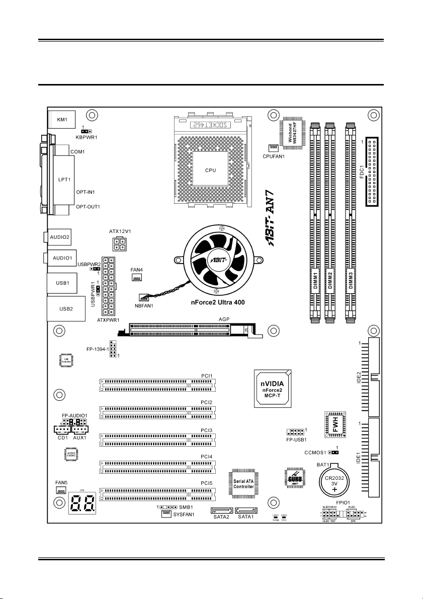
1-2. Layout Diagram
User’s Manual
Page 22

1-4 Chapter 1
AN7
Page 23
Hardware Setup 2-1
Chapter 2. Hardware Setup
Before the Installation: Turn off the power supply switch (fully turn off the +5V standby power), or
disconnect the power cord before installing or unplugging any connectors or add-on cards. Failing to do
so may cause the motherboard components or add-on cards to malfunction or damaged.
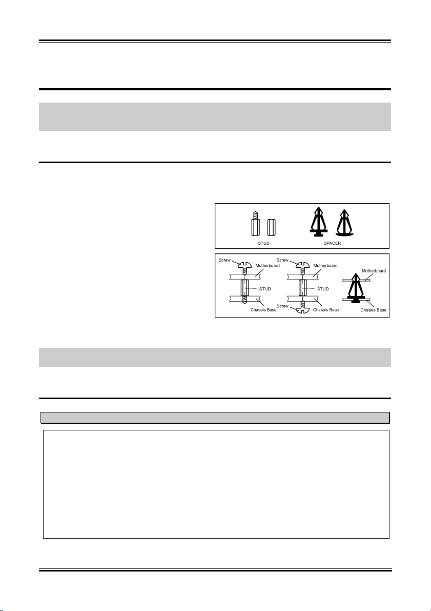
2-1. Install The Motherboard
Most computer chassis have a base with many mounting holes to allow motherboard to be securely
attached on and at the same time, prevented from short circuits. There are two ways to attach the
motherboard to the chassis base:
1. use with studs
2. or use with spacers
In principle, the best way to attach the board is to
use with studs. Only if you are unable to do this
should you attach the board with spacers. Line up
the holes on the board with the mounting holes on
the chassis. If the holes line up and there are
screw holes, you can attach the board with studs.
If the holes line up and there are only slots, you
can only attach with spacers. Take the tip of the
spacers and insert them into the slots. After doing
this to all the slots, you can slide the board into
position aligned with slots. After the board has been positioned, check to make sure everything is OK
before putting the chassis back on.
ATTENTION: To prevent shorting the PCB circuit, please REMOVE the metal studs or spacers if they
are already fastened on the chassis base and are without mounting-holes on the motherboard to align with.
2-2. Install CPU and Heatsink
Note
• Installing a heatsink and cooling fan is necessary for heat to dissipate from your processor.
Failing to install these items may result in overheating and processor damage.
• The AMD Socket A processor will produce a lot of heat while operating, so you need to use a
large heat sink that is especially designed for the AMD socket A processor. Otherwise, it may
result in overheating and processor damage.
• If your processor fan and its power cable are not installed properly, never plug the ATX power
cable into the motherboard. This can prevent possible processor damage.
• Please refer to your processor installation manual or other documentation with your processor for
detailed installation instructions.
User’s Manual
Page 24
2-2 Chapter 2
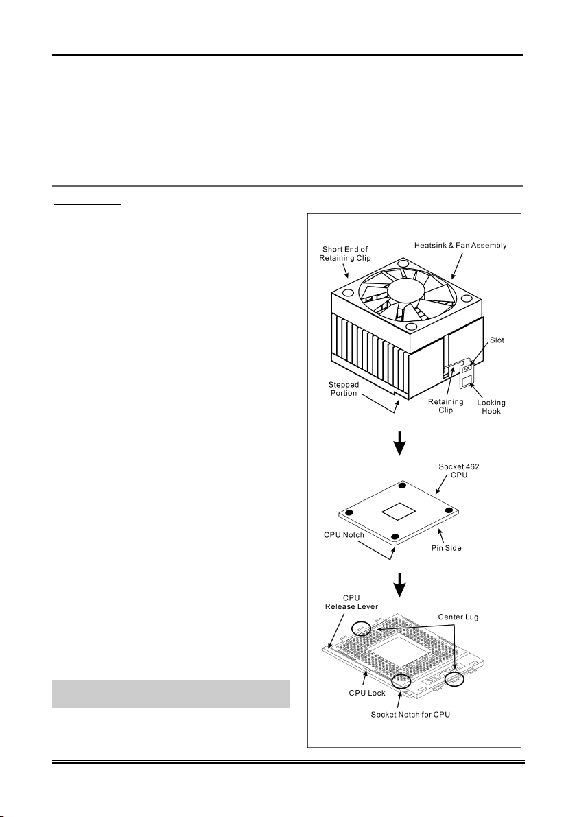
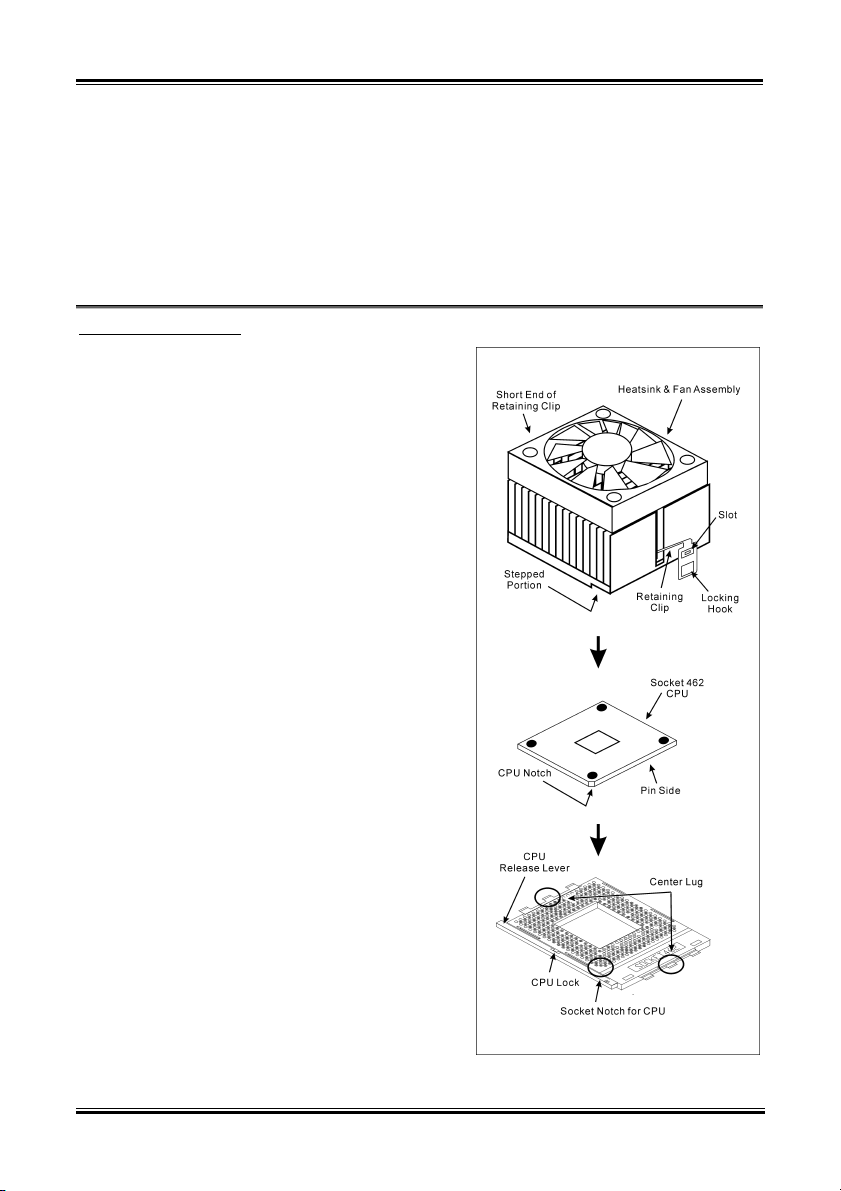
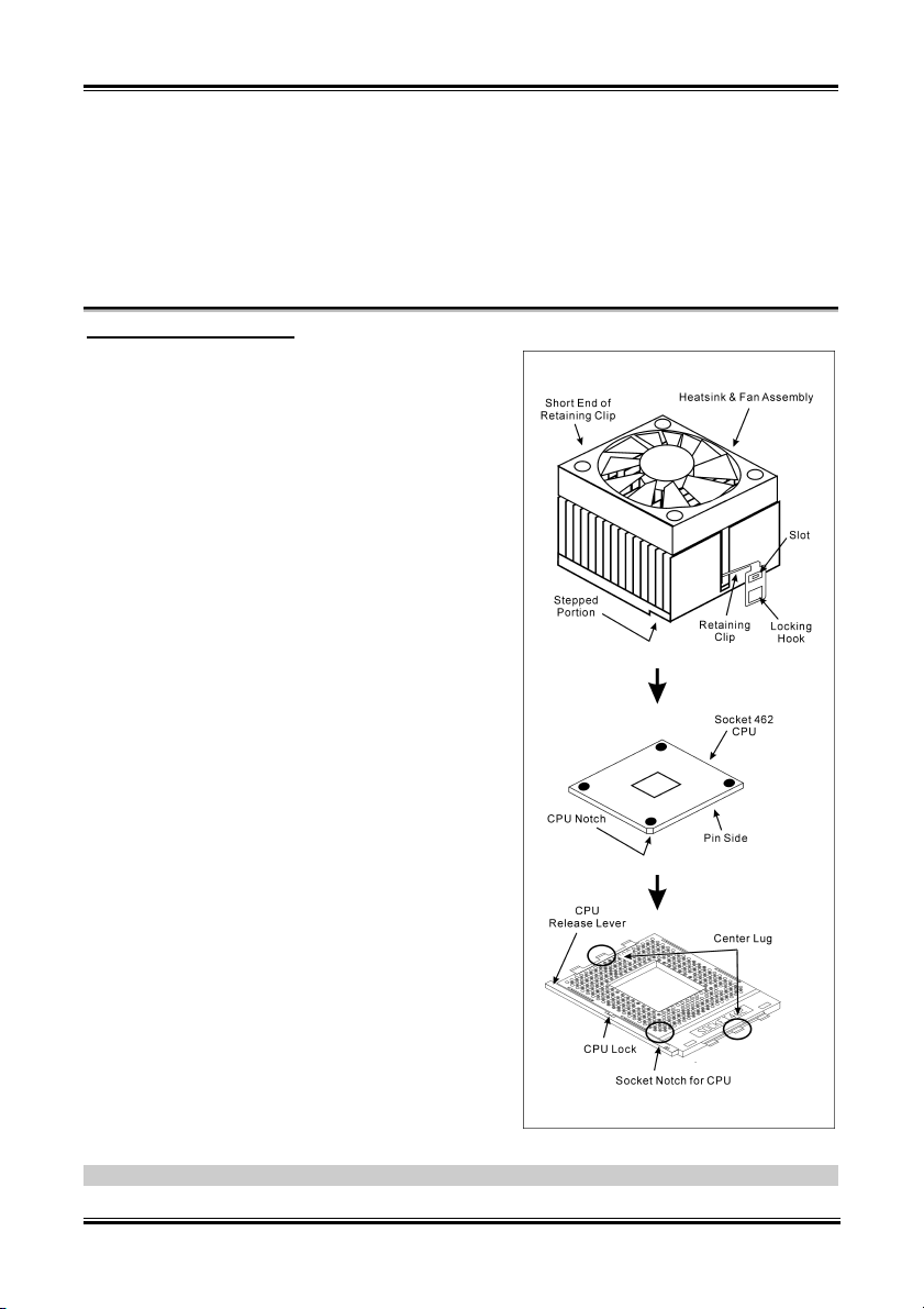
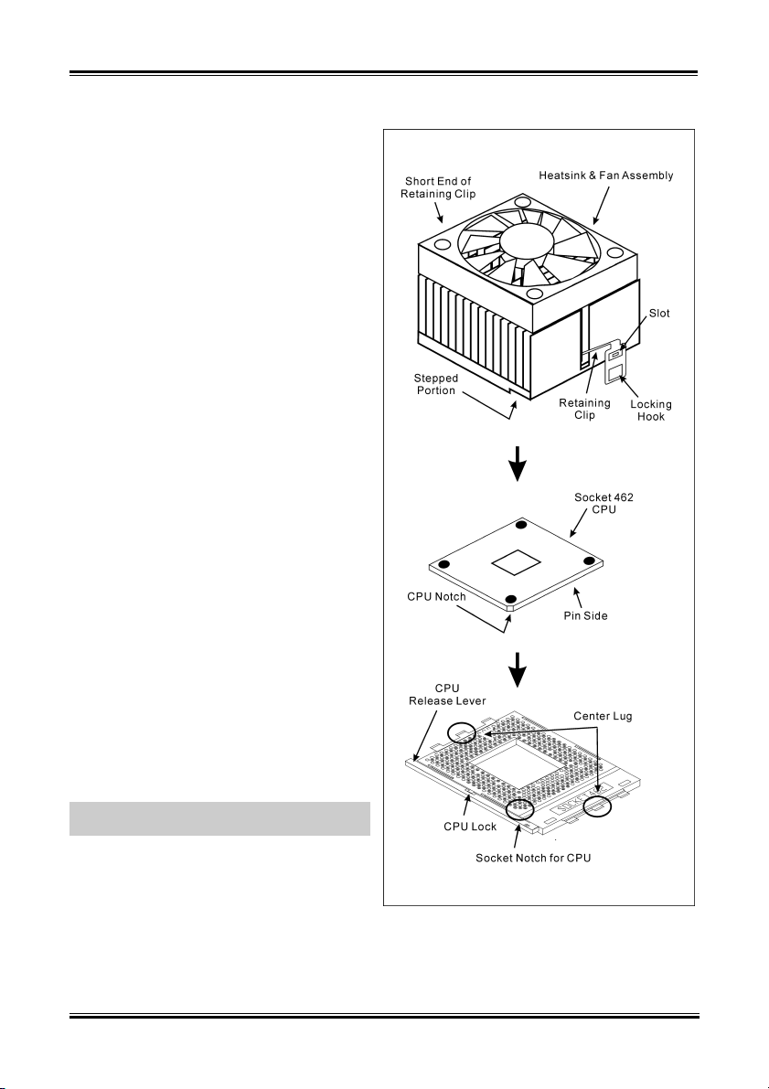
This motherboard provides a ZIF (Zero Insertion
Force) Socket 462 to install AMD Socket A CPU.
The CPU you bought should have a kit of
heatsink and cooling fan along with. If that’s not
the case, buy one specially designed for Socket A.
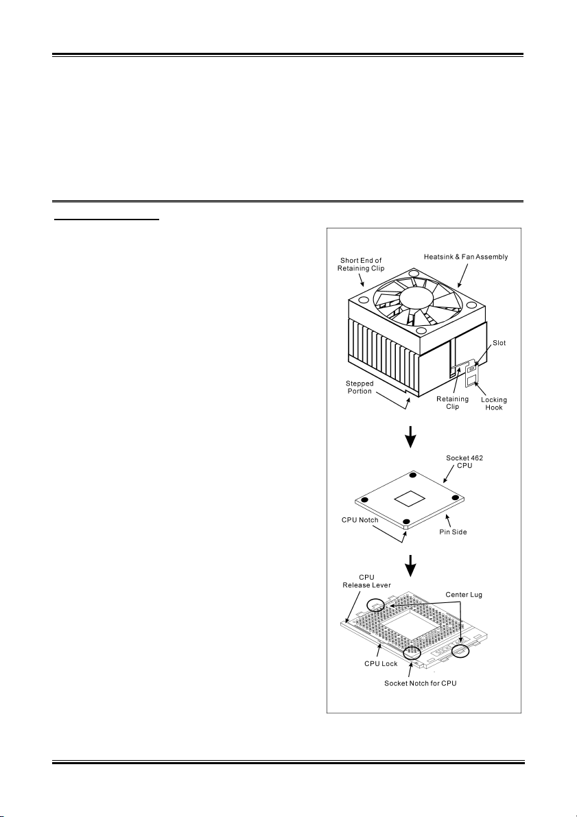
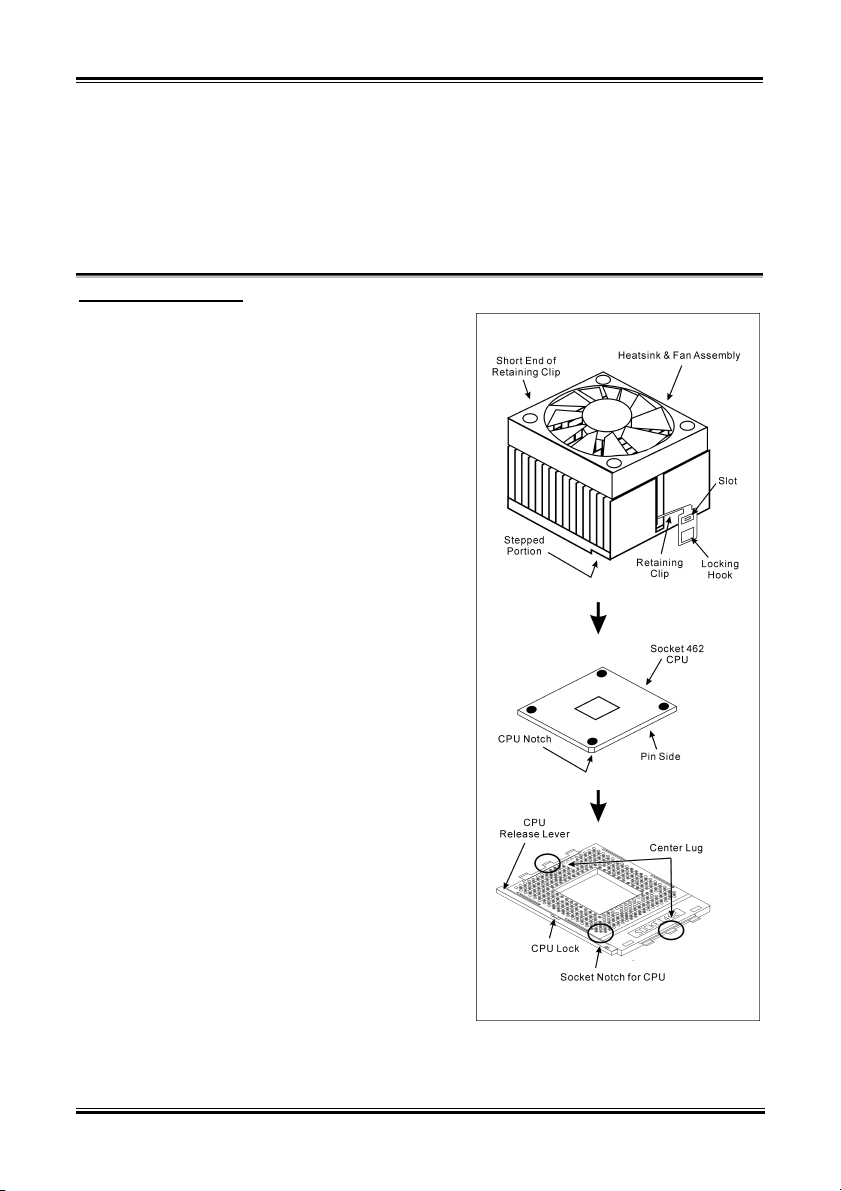
Please refer to the figure shown here to install
CPU and heatsink. (For reference only. Your
Heatsink & Fan Assembly may not be exactly the
same as this one.)
1. Locate the Socket 462 on this motherboard.
Pull the CPU release lever sideways to
unlatch and then raise it all the way up.
2. Align the CPU notch to the socket notch for
CPU. Drop the processor with its pin side
down into the CPU socket. Do not use extra
force to insert CPU; it only fit in one
direction. Close the CPU release lever.
3. Remove the plastic film adhesive on the
heatsink. Make sure the stepped portion of
the heatsink is facing toward the end of the
socket that reads “Socket 462”. Put the
heatsink faces down onto the processor until
it covers the processor completely.
4. Push down the short end of the retaining clip
first to lock up with the center lug at the
bottom of the socket.
5. Use a screwdriver to insert into the slot at the
long end of the retaining clip. Push the clip
downward to lock up with the center lug at
the top of the socket. The heatsink & fan
assembly is now firmly attached on the CPU
socket.
6. Attach the fan connector of Heatsink & Fan
Assembly with the fan connector on the
motherboard.
ATTENTION: Do not forget to set the correct
bus frequency and multiple for your processor.
AN7
Page 25
Hardware Setup 2-3
2-3. Install System Memory
This motherboard provides 3 184-pin DDR DIMM sites for memory expansion available from minimum
128MB to maximum 3GB.
Table 2-1. Valid Memory Configurations
Bank Memory Module Total Memory
Bank 0, 1 (DIMM1) 128, 256, 512MB, 1GB 128MB ~ 1GB
Bank 2, 3 (DIMM2) 128, 256, 512MB, 1GB 128MB ~ 1GB
Bank 4, 5 (DIMM3) 128, 256, 512MB, 1GB 128MB ~ 1GB
Total System Memory for Un-buffered DDR 200/266/333 DIMM 128MB ~ 3GB
Total System Memory for Un-buffered DDR 400 DIMM 128MB ~ 2GB
NOTE: We suggest you to install DDR SDRAM modules from DIMM3 to DIMM1 sockets in order.
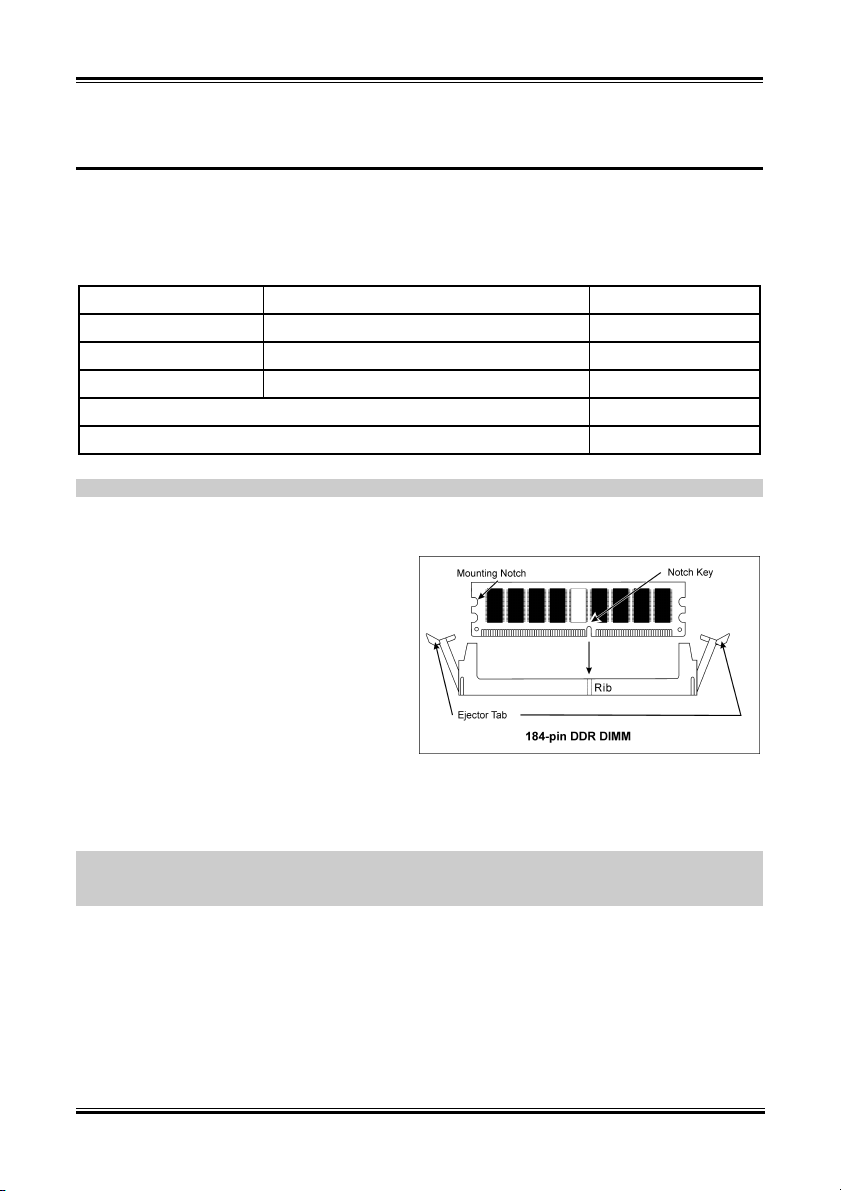
Power off the computer and unplug the AC power cord before installing or removing memory modules.
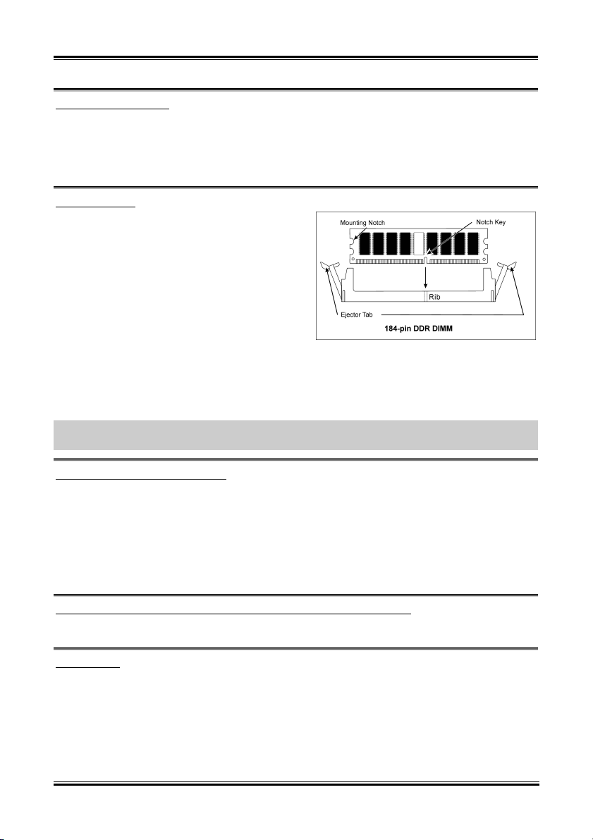
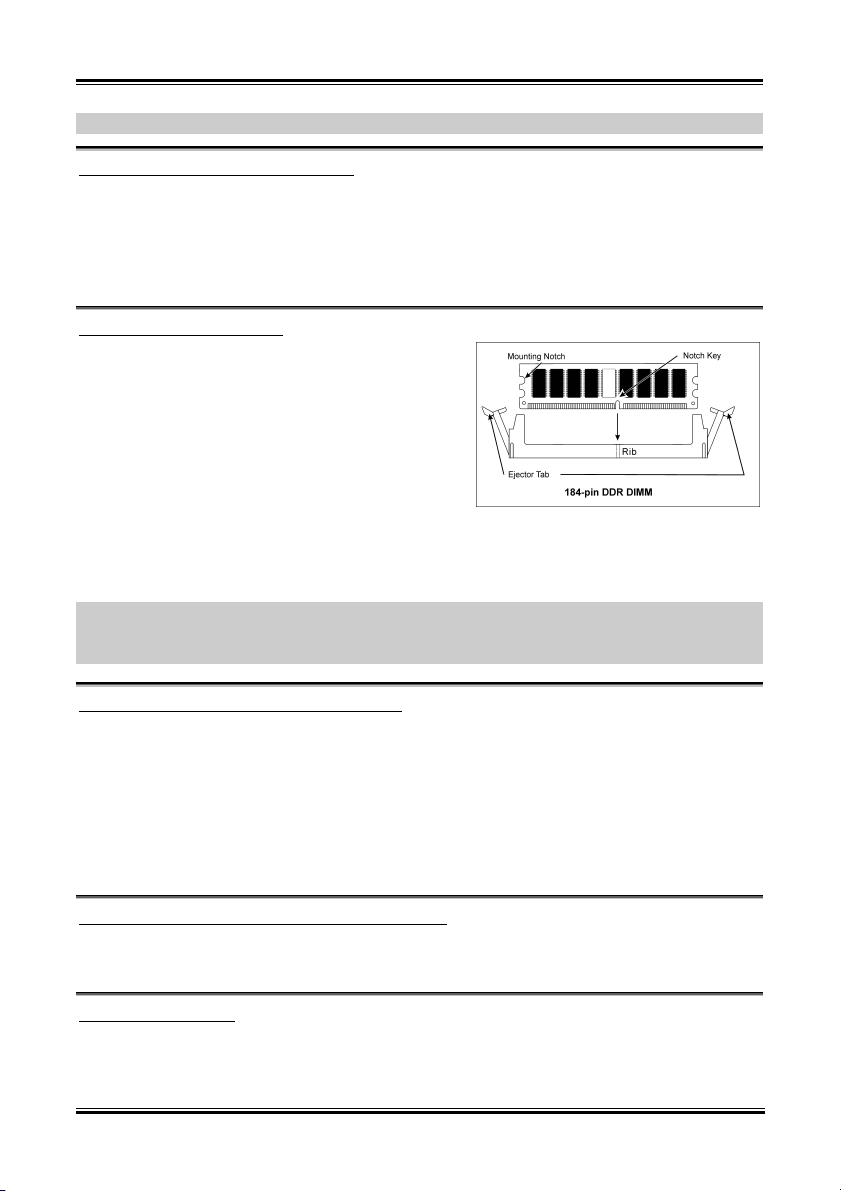
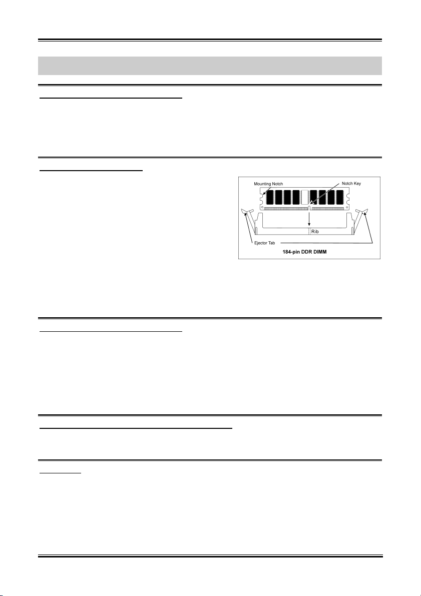
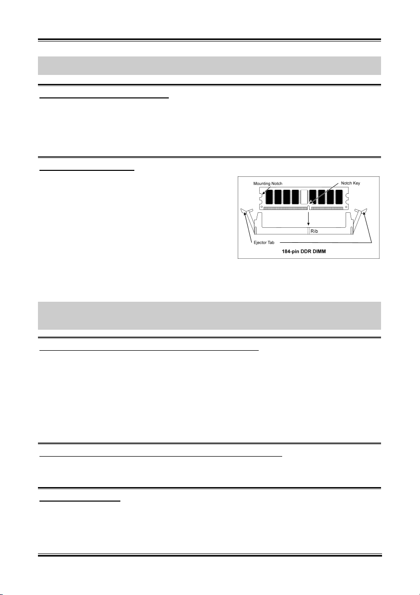
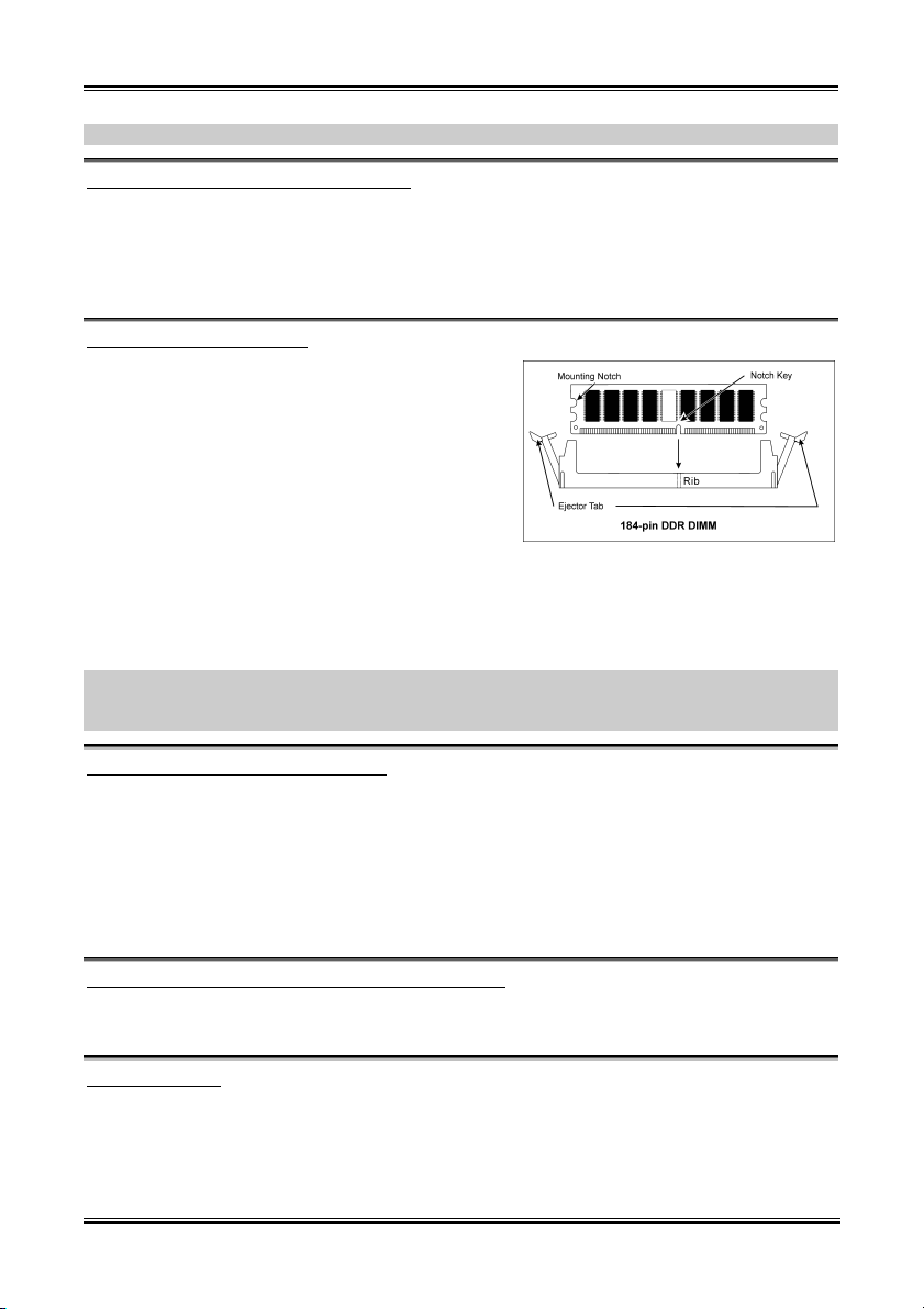
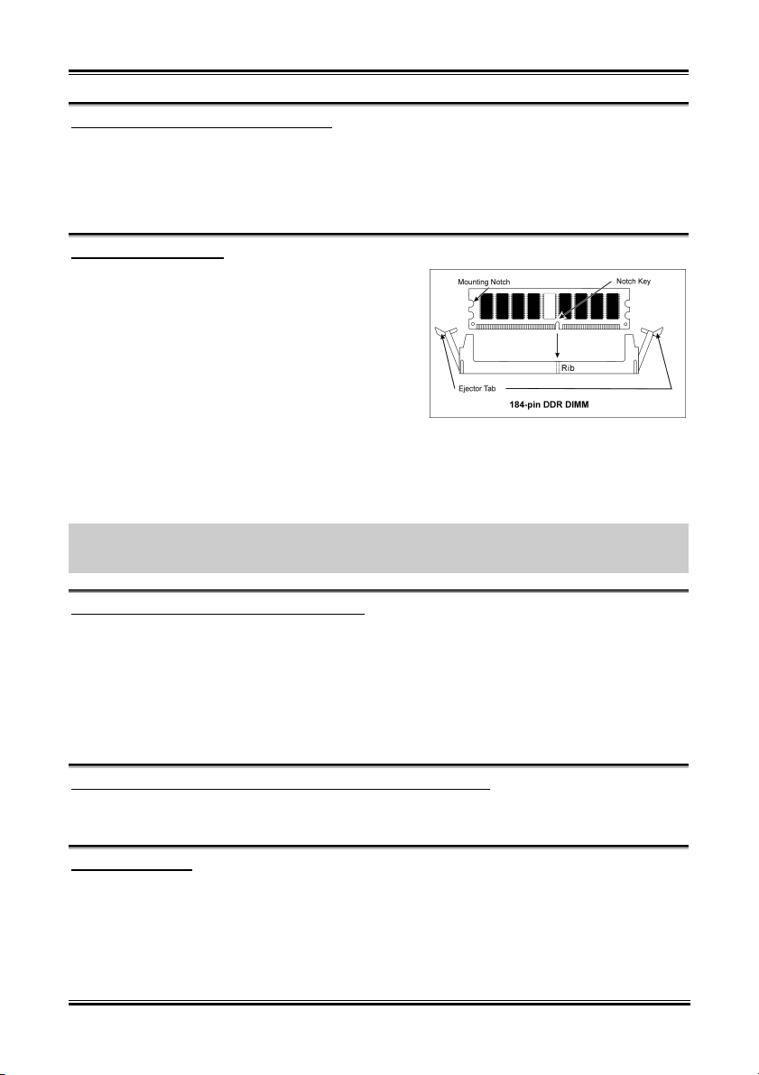
1. Locate the DIMM slot on the board.
2. Hold two edges of the DIMM module
carefully, keep away of touching its
connectors.
3. Align the notch key on the module with the
rib on the slot.
4. Firmly press the module into the slots until
the ejector tabs at both sides of the slot
automatically snaps into the mounting notch.
Do not force the DIMM module in with extra
force as the DIMM module only fit in one direction.
5. To remove the DIMM modules, push the two ejector tabs on the slot outward simultaneously, and
then pull out the DIMM module.
ATTENTION: Static electricity can damage the electronic components of the computer or optional
boards. Before starting these procedures, ensure that you are discharged of static electricity by touching a
grounded metal object briefly.
User’s Manual
Page 26
2-4 Chapter 2
2-4. Connectors, Headers and Switches
Here we will show you all of the connectors, headers and switches, and how to connect them. Please read
the entire section for necessary information before attempting to finish all the hardware installation inside
the computer chassis. A complete enlarged layout diagram is shown in Chapter 1 for all the position of
connectors and headers on the board that you may refer to.
WARNING: Always power off the computer and unplug the AC power cord before adding or removing
any peripheral or component. Failing to so may cause severe damage to your motherboard and/or
peripherals. Plug in the AC power cord only after you have carefully checked everything.
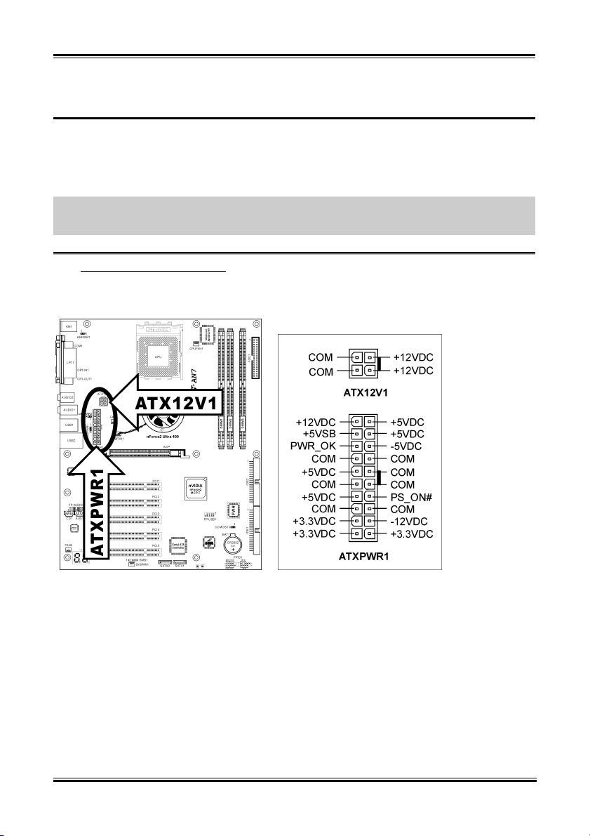
ATX Power Input Connectors
(1).
This motherboard provides two power connectors to connect to an ATX12V power supply with 300W,
20A +5VDC, and 720mA +5VSB capacity at least.
AN7
Page 27
Hardware Setup 2-5
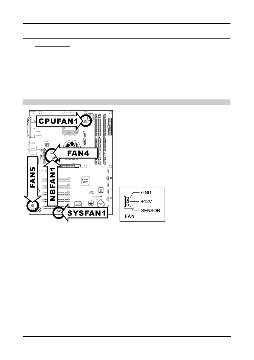
(2). FAN Connectors
These 3-pin connectors each provide power to the cooling fans installed in your system.
• CPUFAN1: CPU Fan
• NBFAN1: Chipset Fan
• SYSFAN1: System Fan
• FAN4, FAN5: Auxiliary Fan
WARNING: These fan connectors are not jumpers. DO NOT place jumper caps on these connectors.
User’s Manual
Page 28

2-6 Chapter 2
(3). CMOS Memory Clearing Header
This header uses a jumper cap to clear the CMOS memory.
• Pin 1-2 shorted (default): Normal operation.
• Pin 2-3 shorted: Clear CMOS memory.
WARNING: Turn the power off first (including the +5V standby power) before clearing the CMOS
memory. Failing to do so may cause your system to work abnormally or malfunction.
AN7
Page 29

Hardware Setup 2-7
(4). Wake-up Header
These headers use a jumper cap to enable/disable the wake-up function.
• KBPWR1:
Pin 1-2 shorted (default): Disable wake-up function support at Keyboard/Mouse port.
Pin 2-3 shorted: Enable wake-up function support at Keyboard/Mouse port.
• USBPWR1:
Pin 1-2 shorted (default): Disable wake-up function support at USB1 port.
Pin 2-3 shorted: Enable wake-up function support at USB1 port.
• USBPWR2:
Pin 1-2 shorted (default): Disable wake-up function support at USB2 port.
Pin 2-3 shorted: Enable wake-up function support at USB2 port
User’s Manual
Page 30

2-8 Chapter 2
(5). Front Panel Switches & Indicators Headers
This header is used for connecting switches and LED indicators on the chassis front panel.
Watch the power LED pin position and orientation. The mark “+” align to the pin in the figure below
stands for positive polarity for the LED connection. Please pay attention to connect these headers. A
wrong orientation will only cause the LED not lighting, but a wrong connection of the switches could
cause system malfunction.
• HLED (Pin 1, 3):
Connects to the HDD LED cable of chassis front panel.
• RST (Pin 5, 7):
Connects to the Reset Switch cable of chassis front panel.
• SPK (Pin 15, 17, 19, 21):
Connects to the System Speaker cable of chassis.
• SLED (Pin 2, 4):
Connects to the Suspend LED cable (if there is one) of chassis front panel.
• PWR-ON (Pin 6, 8):
Connects to the Power Switch cable of chassis front panel.
• PLED (Pin 16, 18, 20):
Connects to the Power LED cable of chassis front panel.
AN7
Page 31

Hardware Setup 2-9
(6). Additional USB Port Header
This header provides 2 additional USB 2.0 ports connection through an USB cable designed for USB 2.0
specifications.
Pin Pin Assignment Pin Pin Assignment
1 VCC 2 VCC
3 Data0 - 4 Data1 -
5 Data0 + 6 Data1 +
7 Ground 8 Ground
9 NC 10 NC
User’s Manual
Page 32

2-10 Chapter 2
(7). Additional IEEE1394 Port Header
This header provides one additional IEEE1394 port connection through an extension cable and bracket.
Pin Pin Assignment Pin Pin Assignment
1 TPA0 + 2 TPA0 -
3 GND 4 GND
5 TPB0 + 6 TPB0 -
7 +12V 8 +12V
9 NC 10 GND
AN7
Page 33

Hardware Setup 2-11
(8). Front Panel Audio Connection Header
This header provides the connection to audio connector at front panel.
• To use the audio connector at front panel, remove all the jumpers on this header, and then
connect to front panel by the extension cable provided with the chassis.
• To use the audio connector at rear panel, disconnect the extension cable, attach the jumpers back
at pin 5-6, and pin 9-10 (default setting).
Pin Pin Assignment Pin Pin Assignment
1 Audio Mic. 2 Ground
3 Audio Mic. Bias 4 VCC
Speaker Out Right
5
Channel
Speaker Out Right
6
Channel Return
7 X 8 NC
Channel
Speaker Out Left
9
Speaker Out Left
10
Channel Return
11 Ground 12 S/PDIF In
13 VCC 14 S/PDIF Out
User’s Manual
Page 34

2-12 Chapter 2
(9). Internal Audio Connectors
These connectors connect to the audio output of internal CD-ROM drive or add-on card.
AN7
Page 35

Hardware Setup 2-13
(10). Accelerated Graphics Port Slot
This slot supports an optional AGP graphics card up to AGP 8X mode. Please refer to our Web site for
more information on graphics cards.
ATTENTION: This motherboard does not support 3.3V AGP cards. Use only 1.5V or 0.8V AGP cards.
User’s Manual
Page 36

2-14 Chapter 2
(11). Floppy Disk Drive Connector
This connector supports two standard floppy disk drives via a 34-pin 34-conductor ribbon cable.
Connecting the Floppy Disk Drive Cable:
1. Install one end of the ribbon cable into the FDC1 connector. The colored edge of the ribbon cable
should be aligned with pin-1 of FDC1 connector.
2. Install the other end(s) of ribbon cable into the disk drive connector(s). The colored edge of the
ribbon cable should be also aligned with pin-1 of disk drive connector. The endmost connector
should be attached to the drive designated as Drive A.
AN7
Page 37

Hardware Setup 2-15
(12). IDE Connectors
This motherboard provides two IDE ports to connect up to four IDE drives at Ultra DMA mode by Ultra
ATA/66 ribbon cables. Each cable has 40-pin 80-conductor and three connectors, providing two hard
drives connection with motherboard. Connect the single end (blue connector) at the longer length of
ribbon cable to the IDE port on motherboard, and the other two ends (gray and black connector) at the
shorter length of the ribbon cable to the connectors on hard drives.
If you want to connect two hard drives together through one IDE channel, you must configure the second
drive to Slave mode after the first Master drive. Please refer to the drives’ documentation for jumper
settings. The first drive connected to IDE1 is usually referred to as “Primary Master”, and the second
drive as “Primary Slave”. The first drive connected to IDE2 is referred to as “Secondary Master” and the
second drive as “Secondary Slave”.
Keep away from connecting one legacy slow speed drive, like CD-ROM, together with another hard drive
on the same IDE channel; this will drop your integral system performance.
User’s Manual
Page 38

2-16 Chapter 2
(13). Serial ATA Connectors
These connectors are provided to attach one Serial ATA device at each channel via Serial ATA cable.
To enable the SATA1 and SATA2 controller, the item “Serial ATA Controller” must be kept enabled
(default setting) in the BIOS menu of “Onboard PCI Device”.
AN7
Page 39

Hardware Setup 2-17
(14). Status Indicators
• LED1 (5VSB): This LED lights up when the power supply is connected with power source.
• LED2 (VCC): This LED lights up when the system power is on.
User’s Manual
Page 40

2-18 Chapter 2
(15). System Management Bus Headers
This header is reserved for system management bus (SM bus). The SM bus is a specific implementation
2
of an I
C bus. I2C is a multi-master bus, which means that multiple chips can be connected to the same
bus and each one can act as a master by initiating a data transfer. If more than one master simultaneously
tries to control the bus, an arbitration procedure decides which master gets priority.
AN7
Page 41

Hardware Setup 2-19
(16). POST Code Display
This is an LED device to display the “POST” Code, the acronym of Power On Self Test. The computer
will execute the POST action whenever you power on the computer. The POST process is controlled by
the BIOS. It is used to detect the status of the computer’s main components and peripherals. Each POST
Code corresponds to different checkpoints that are also defined by the BIOS in advance. For example,
“memory presence test” is an important checkpoint and its POST Code is “C1”. When the BIOS execute
any POST item, it will write the corresponding POST Code into the address 80h. If the POST passes, the
BIOS will process the next POST item and write the next POST Code into the address 80h. If the POST
fails, we can check the POST Code in address 80h to find out where the problem lies.
This LED device also displays the “POST” Code of AC2003, an “uGuru” chipset developed exclusively
by ABIT computer.
NOTE: The decimal point lights up when executing the AC2003 POST action.
See Appendix for both AWARD and AC2003 POST Code definition.
User’s Manual
Page 42

2-20 Chapter 2
(17). Back Panel Connectors
• Mouse: Connects to PS/2 mouse.
• Keyboard: Connects to PS/2 keyboard.
• LPT1: Connects to printer or other devices that support this communication protocol.
• COM1: Connects to external modem, mouse or other devices that support this communication
protocol.
• OPT-IN1: This connector provides an S/PDIF in connection through optical fiber to digital
multimedia devices.
• OPT-OUT1: This connector provides an S/PDIF out connection through optical fiber to digital
multimedia devices.
• AUDIO2:
R.L./R.R. (Rear Left / Rear Right): Connects to the rear left and rear right channel in the 5.1
channel audio system.
Cen./Sub. (Center / Subwoofer): Connects to the center and subwoofer channel in the 5.1
channel audio system.
• AUDIO1:
Mic In: Connects to the plug from external microphone.
Line In: Connects to the line out from external audio sources.
F.L./F.R. (Front Left / Front Right): Connects to the front left and front right channel in the
5.1-channel or regular 2-channel audio system.
• IEEE1394: Connects to devices of IEEE1394 protocol.
• LAN: Connects to Local Area Network.
• USB1/USB2: Connects to USB devices such as scanner, digital speakers, monitor, mouse,
keyboard, hub, digital camera, joystick etc.
AN7
Page 43

BIOS Setup 3-1
Chapter 3. BIOS Setup
This motherboard provides a programmable EEPROM that you can update the BIOS utility. The BIOS
(Basic Input/Output System) is a program that deals with the basic level of communication between
processor and peripherals. Use the BIOS Setup program only when installing motherboard, reconfiguring
system, or prompted to “Run Setup”. This chapter explains the Setup Utility of BIOS utility.
After powering up the system, the BIOS message appears on the screen, the memory count begins, and
then the following message appears on the screen:
PRESS DEL TO ENTER SETUP
If this message disappears before you respond, restart the system by pressing <Ctrl> + <Alt> + <Del>
keys, or by pressing the Reset button on computer chassis. Only when it failed by these two methods can
you restart the system by powering it off and then back on.
After pressing <Del> key, the main menu screen appears.
NOTE: In order to increase system stability and performance, our engineering staffs are constantly
improving the BIOS menu. The BIOS setup screens and descriptions illustrated in this manual are for
your reference only, may not completely match what you see on your screen.
In the BIOS Setup main menu, you can see several options. We will explain these options step by step in
the following pages of this chapter, but let us first see a short description of the function keys you may
use here.
Esc:
Press this button to quit the BIOS Setup.
→:
↑↓←
Press these buttons to choose, in the main menu, the option you want to confirm or to modify.
F10:
When you have completed the setup of BIOS parameters, press this button to save these parameters and
to exit the BIOS Setup menu.
User’s Manual
Page 44

3-2 Chapter 3
F6:
You may create a profile to save the new BIOS settings in it. Press <F6> button in the main menu, a
dialog box with five numbers (1~5) will appear on the screen. Select one number, and press <Enter>.
Then, you will get a confirmation dialog box with a message similar to:
Save Profile To BIOS (Y/N)?
After pressing “Y”, the following message will appear to assist you in creating a name for the profile.
Enter Profile Name:
Type the profile name, and press <Enter>. The new BIOS settings now are saved to the selected profile.
NOTE: You may save up to five profiles to BIOS.
F7:
Press <F7> button in the main menu, a dialog box with five numbers (1~5) will appear on the screen.
Select the profile you want, and press <Enter>. Then, you will get a confirmation dialog box with a
message similar to:
Load Profile From BIOS (Y/N)?
Press “Y” to load the BIOS settings in this profile.
AN7
Page 45

BIOS Setup 3-3
3-1. SoftMenu Setup
The SoftMenu utility is ABIT’s exclusive and ultimate solution in programming the CPU operating speed.
All the parameters regarding CPU FSB speed, multiplier factor, the AGP & PCI clock, and even the CPU
core voltage are all available at your fingertips.
CPU Name Is:
This item displays the CPU model name, for example: AMD Athlon(tm) XP.
CPU Internal Frequency:
This item displays the CPU internal clock speed.
CPU Operating Speed:
This item displays the CPU operating speed according to the type and speed of your CPU. You can also
select the [User Define] option to enter the manual option.
User Define:
WARNING: The wrong settings of the multiplier and external clock in certain circumstances may cause
CPU damage. Setting the working frequency higher than the PCI chipset or processor specs, may cause
abnormal memory module functioning, system hangs, hard disk drive data lose, abnormal functioning of
the VGA card, or abnormal functioning with other add-on cards. Using non-specification settings for your
CPU is not the intention of this explanation. These should be used for engineering testing, not for normal
applications.
There will be no guaranty for the settings beyond specification, any damage of any component on this
motherboard or peripherals result therein is not our responsibility.
External Clock:
This item sets the CPU Front Side Bus speed from 100 to 300. Due to the specification limit of the CPU
you installed, the speed you set over its standard bus speed is supported, but not guaranteed.
Multiplier Factor:
This item sets the multiplier factor for the CPU you installed.
User’s Manual
Page 46

3-4 Chapter 3
NOTE: Some processors might have this multiplier factor locked, so there is no way to choose a higher
multiplier factor.
AGP Frequency:
This item allows you to set the AGP clock speed from 66MHz to 99MHz. Due to the AGP specification
limit, the speed you set over its standard clock speed is supported, but not guaranteed.
CPU FSB/DRAM ratio:
This item allows you to set the frequency ratio between CPU and DRAM.
CPU Interface:
Two options are available: Disabled Enabled. The default setting is Disabled. When set to Disabled,
the system uses the most stable CPU/FSB parameters. If you choose enabled, the system will use
overclocked CPU/FSB parameters.
Power Supply Controller:
This option allows you to switch between the default and user-defined voltages. Leave this setting to
default unless the current voltage setting cannot be detected or is not correct. The option “User Define”
enables you to select the following voltages manually.
CPU Core Voltage:
This item selects the CPU core voltage.
DDR SDRAM Voltage:
This item selects the voltage for DRAM slot.
NB Core Voltage:
This item selects the NB core voltage.
AGP Voltage:
This item selects the voltage for AGP slot.
ATTENTION: A wrong voltage setting may cause the system unstable or even damage the CPU. Please
leave it to default settings unless you are fully aware of its consequences.
Press F8 to OC on the Fly:
After a new configuration on items “External Clock” and “Voltage”, pressing <F8> button now in this
menu will make it become effective immediately.
ATTENTION: An external clock too much over its specification may cause the system unstable or even
fail, please proceed with highly attention.
AN7
Page 47

BIOS Setup 3-5
3-2. Standard CMOS Features
This section contains the basic configuration parameters of the BIOS. These parameters include date,
hour, VGA card, FDD and HDD settings.
Date (mm:dd:yy):
This item sets the date you specify (usually the current date) in the format of [Month], [Date], and [Year].
Time (hh:mm:ss):
This item sets the time you specify (usually the current time) in the format of [Hour], [Minute], and
[Second].
IDE Primary Master / Slave and IDE Secondary Master / Slave:
Click <Enter> key to enter its submenu:
IDE HDD Auto-Detection:
This item allows you to detect the parameters of IDE drives by pressing <Enter> key. The parameters will
be shown on the screen automatically.
User’s Manual
Page 48

3-6 Chapter 3
IDE Primary Master / Slave and IDE Secondary Master / Slave:
When set to [Auto], the BIOS will automatically check what kind of IDE drive you are using. If you want
to define your own drive by yourself, set it to [Manual] and make sure you fully understand the meaning
of the parameters. Please refer to the instruction manual provided by the device’s manufacturer to get the
setting right.
Access Mode:
This item selects the mode to access your IDE devices. Leave this item to its default [Auto] setting to
detect the access mode of your HDD automatically.
Capacity:
This item displays the approximate capacity of the disk drive. Usually the size is slightly greater than the
size of a formatted disk given by a disk-checking program.
Cylinder:
This item configures the numbers of cylinders.
Head:
This item configures the numbers of read/write heads.
Precomp:
This item displays the number of cylinders at which to change the write timing.
Landing Zone:
This item displays the number of cylinders specified as the landing zone for the read/write heads.
Sector:
This item configures the numbers of sectors per track.
Back to Standard CMOS Features Setup Menu:
Drive A & Drive B:
This item sets the type of floppy drives (usually only Drive A) installed.
Floppy 3 Mode Support:
This item allows you to use “3 Mode Floppy Drive” in Japanese computer system by selecting drive A, B,
or both. Leave this item to its default [Disabled] setting if you are not using this Japanese standard floppy
drive.
Video:
This item selects the type of video adapter used for the primary system monitor.
AN7
Page 49

BIOS Setup 3-7
[EGA/VGA]: (Enhanced Graphics Adapter/Video Graphics Array) For EGA, VGA, SVGA and PGA
monitor adapters.
[CGA 40]: (Color Graphics Adapter) Power up in 40-column mode.
[CGA 80]: (Color Graphics Adapter) Power up in 80-column mode.
[Mono]: (Monochrome adapter) Includes high-resolution monochrome adapters.
Halt On:
This item determines whether the system stops if an error is detected during system boot-up.
[All Errors]: The system-boot will stop whenever the BIOS detect a non-fatal error.
[No Errors]: The system-boot will not stop for any error detected.
[All, But Keyboard]: The system-boot will stop for all errors except a keyboard error.
[All, But Diskette]: The system-boot will stop for all errors except a diskette error.
[All, But Disk/Key]: The system-boot will stop for all errors except a diskette or keyboard error.
Base Memory:
This item displays the amount of base memory installed in the system. The value of the base memory is
typically 640K for system with 640K or more memory size installed on the motherboard.
Extended Memory:
This item displays the amount of extended memory detected during system boot-up.
Total Memory:
This item displays the total memory available in the system.
User’s Manual
Page 50

3-8 Chapter 3
3-3. Advanced BIOS Features
Hard Disk Boot Priority:
This item selects the hard disks booting priority. By pressing <Enter> key, you can enter its submenu
where the hard disks detected can be selected for the booting sequence to boot up system.
This item functions only when there is the option of [Hard Disk] in any one of the First/Second/Third
Boot Device items.
Virus Warning:
When set to [Enabled], the BIOS will monitor the boot sector and partition table of the hard disk drive. If
there is any attempt of writing to the boot sector or partition table of the hard disk drive, the BIOS will
halt the system and an error message will appear.
Quick Power On Self Test:
When set to [Enabled], this item speeds up the Power On Self Test (POST) after powering on the system.
The BIOS shorten or skip some check during the POST.
First Boot Device / Second Boot Device / Third Boot Device / Boot Other Device:
Select the drive to boot first, second and third in the [First Boot Device], [Second Boot Device], and
[Third Boot Device] items respectively. The BIOS will boot the operating system according to the
sequence of the drive selected. Set [Boot Other Device] to [Enabled] if you wish to boot from another
device other than these three items.
Swap Floppy Drive:
When set to [Enabled], and the system is booting from the floppy drive, the system will boot from drive B
instead of the regular drive A. There must be two floppy drives connected in the system to use this
function.
Boot Up Floppy Seek:
When set to [Enabled], the BIOS will check whether the floppy disk drive is installed or not.
AN7
Page 51

BIOS Setup 3-9
Boot Up NumLock Status:
This item determines the default state of the numeric keypad at system booting up.
[On]: The numeric keypad functions as number keys.
[Off]: The numeric keypad functions as arrow keys.
Security Option:
This item determines when the system will prompt for password - every time the system boots or only
when enters the BIOS setup.
[Setup]: The password is required only when accessing the BIOS Setup.
[System]: The password is required each time the computer boots up.
NOTE: Don’t forget your password. If you forget the password, you will have to open the computer case
and clear all information in the CMOS before you can start up the system. But by doing this, you will
have to reset all previously set options.
APIC Mode:
Leave this item to its default setting.
MPS Version Ctrl For OS:
This item specifies which version of MPS (Multi-Processor Specification) this motherboard will use. The
options are 1.1 and 1.4. The default setting is 1.4. If you use an older OS for dual processor executing,
please set this option to 1.1.
OS Select For DRAM > 64MB:
This item allows you to access the memory that is over 64MB in OS/2. Leave this item to its default
[Non-OS2] setting for operating system other than OS/2.
Report No FDD For OS:
When set to [Enabled], this item allows you to run some older operating system without floppy disk drive.
Leave this item to its default setting.
Delay IDE Initial:
This item allows the BIOS to support some old or special IDE devices by prolonging this delay time. A
larger value will give more delay time to the device for which to initialize and to prepare for activation.
User’s Manual
Page 52

3-10 Chapter 3
3-4. Advanced Chipset Features
Enhance PCI Performance:
Two options are available: Disabled Enabled. The default setting is Disabled. This item can improve
the PCI transmission performance.
CPU Disconnect Function:
When set to [Enabled], the system will disconnect the S2K FSB on a C1 state change.
Memory Timings:
Five options are available: Optimal Aggressive Turbo By SPD Expert. The default setting is
Optimal. Choose Optimal for better memory compatibility; choose Aggressive/Turbo for better memory
performance; choose Expert for user-define. When set to By SPD, the BIOS will read the DRAM module
SPD data and automatically set to the values stored in it.
Row-active delay:
Fifteen options are available: from 1 to 15. This option specifies the row active time. This is the minimum
number of cycles between an activate command and a precharge command to the same bank.
RAS-to-CAS delay:
Seven options are available: from 1 to 7. This item is to set SDR/DDR SDRAM RAS to CAS delay. It
can define the SDRAM ACT to Read/Write command period.
Row-precharge delay:
Seven options are available: from 1 to 7. This item controls the idle clocks after issuing a precharge
command to the DRAM.
CAS Latency:
Three options are available: 2.0 2.5 3.0. The default setting is 2.5. You can select SDRAM CAS
(Column Address Strobe) latency time according your SDRAM specification.
AN7
Page 53

BIOS Setup 3-11
FSB Spread Spectrum:
Three options are available: Disabled 0.50% 1.00%. The default setting is 0.50%.
AGP Spread Spectrum:
Two options are available: Disabled 0.50%. The default setting is 0.50%.
AGP Aperture Size:
This option specifies the amount of system memory that can be used by the AGP device. The aperture is a
portion of the PCI memory address range dedicated for graphics memory address space.
AGP Data Transfer Rate:
This item selects the data transfer rate of AGP device. A higher rate delivers faster and better graphics to
your system. Make sure your graphics card supports the mode you select.
AGP Fast Write Capability:
Two options are available: Disabled Enabled. The default setting is Enabled. If your AGP adapter can
support this function, then you can choose Enabled. Otherwise, choose Disabled.
CPU Thermal-Throttling:
Eight options are available: Disabled 87.5% 75.0% 62.5% 50.0% 37.5% 25.0%
12.5%. The default setting is 50.0%.
System BIOS Cacheable:
Two options are available: Disabled or Enabled. The default setting is Enabled. When you select Enabled,
you get faster system BIOS executing speed via the L2 cache.
Video RAM Cacheable:
Two options are available: Disabled or Enabled. The default setting is Enabled. When you select Enable,
you get faster video RAM executing speed via the L2 cache. You must check your VGA adapter manual
to find out if any compatibility problems will occur.
User’s Manual
Page 54

3-12 Chapter 3
3-5. Integrated Peripherals
OnChip IDE Device:
Click <Enter> key to enter its submenu:
OnChip IDE1 Controller:
This item allows you to enable or disable the primary and secondary IDE controller. Select [Disabled] if
you want to add a different hard drive controller.
Master/Slave Drive PIO Mode
The PIO (Programmed Input/Output) mode allows the BIOS to tell the controller what it wants and then
let the controller and the CPU perform the complete task, rather than having the BIOS issue a series of
commands to affect a transfer to or from the disk drive.
[Auto]: The BIOS will select the best available mode after checking your disk drive.
[Mode 0-4]: You can select a mode that matches your disk drive’s timing. Do not use the wrong setting
or you will have drive errors.
Master/Slave Drive Ultra DMA
This item allows you to set the Ultra DMA in use.
[Auto]: The BIOS will select the best available option after checking your hard drive or CD-ROM.
AN7
Page 55

BIOS Setup 3-13
[Disabled]: The BIOS will not detect these categories. If problem arises in using Ultra DMA devices, try
disabling this item.
OnChip IDE2 Controller:
The description is same as the OnChip IDE1 Controller.
IDE Prefetch Mode:
Two options are available: Disabled or Enabled. The default setting is Enabled. The onboard IDE drive
interfaces supports IDE prefetching for faster drive accesses. If you install a primary and/or secondary
add-in IDE interface, set this field to Disabled if the interface does not support prefetching.
IDE Bus Master:
This option enables or disables the IDE bus mastering capability under the DOS environment.
Back to Integrated Peripherals Setup Menu:
OnChip PCI Device:
Click <Enter> key to enter its submenu:
USB Controller:
Three options are available: Disabled V1.1+V2.0 V1.1. The default setting is V1.1+V2.0. If you
choose to disable this item, the “USB Keyboard Support” and “USB Mouse Support” items will not be
able to select in Integrated Peripherals menu.
USB KB, Storage Support:
This item allows you to select [BIOS] for using USB keyboard/USB storage device in DOS environment,
or [OS] in OS environment.
USB Mouse Support:
This item allows you to select [BIOS] for using USB mouse in DOS environment, or [OS] in OS
environment.
Audio Controller:
This option enables or disables the audio controller.
User’s Manual
Page 56

3-14 Chapter 3
LAN Controller:
This option enables or disables the LAN controller.
LAN Boot ROM:
This item allows you to use the boot ROM (instead of a disk drive) to boot-up the system and access the
local area network directly.
IEEE1394 Controller:
This option enables or disables the IEEE 1394 controller.
Back to Integrated Peripherals Setup Menu:
Onboard PCI Device:
Click <Enter> key to enter its submenu:
Serial ATA Controller:
This option enables or disables the onboard Silicon Image SIL3112A SATA controller.
Back to Integrated Peripherals Setup Menu:
Init Display First:
This item selects to initialize AGP or PCI Slot first when the system boots.
[PCI Slot]: When the system boots, it will first initialize PCI.
[AGP]: When the system boots, it will first initialize AGP.
EXT-P2P’s Discard Time:
This item allows you to set EXT-P2P’s discard time.
Onboard FDD Controller:
Two options are available: Enabled and Disabled. The default setting is Enabled. You can enable or
disable the onboard FDD controller.
AN7
Page 57

BIOS Setup 3-15
Onboard Serial Port 1:
This is used to specify the I/O address and IRQ of Serial Port 1. Six options are available: Disabled
3F8/IRQ4 2F8/IRQ3 3E8/IRQ4 2E8/IRQ3 AUTO. The default setting is 3F8/IRQ4.
Onboard Parallel Port:
Sets the I/O address and IRQ of the onboard parallel port. Four options are available: Disabled
378/IRQ7 278/IRQ5 3BC/IRQ7. Default setting is 378/IRQ7.
Parallel1 Port Mode:
Four options are available: SPP EPP ECP ECP+EPP. The default setting is ECP+EPP mode.
EPP Mode Select:
Two options are available: EPP1.7 EPP1.9. The default setting is EPP 1.9. When the mode selected
for the parallel port mode is EPP, the two EPP version options are available.
ECP Mode Use DMA:
Two options are available: 1 3. The default setting is 3. When the mode selected for the parallel port
mode is ECP, the DMA channel selected can be Channel 1 or Channel 3.
User’s Manual
Page 58

3-16 Chapter 3
3-6. Power Management Setup
ACPI Suspend Type:
This item selects the type of Suspend mode.
[S1(PowerOn-Suspend)]: Enables the Power On Suspend function.
[S3(Suspend-To-RAM)]: Enables the Suspend to RAM function.
Power Button Function:
This item selects the method of powering off your system:
[Instant-Off]: Pressing and then releasing the power button at once will immediately power off the
system.
[Delay 4 Sec.]: Pushing the power button for more than 4 seconds will power off the system. This will
prevent the system from powering off in case you accidentally hit or pushed the power button.
Wakeup by PME# of PCI:
Two options are available: Disabled or Enabled. The default setting is Disabled. When set to Enabled,
any event affecting from PCI card (PME) will awaken a system that has powered down.
Wakeup by Ring:
Two options are available: Disabled or Enabled. The default setting is Disabled. When set to Enabled,
any event affecting from Modem Ring will awaken a system that has powered down.
Wakeup by Alarm:
Two options are available: Disabled or Enabled. The default setting is Disabled. When set to Enabled,
you can set the date and time at which the RTC (real-time clock) alarm awakens the system from Suspend
mode.
Day of Month Alarm/ Time (hh:mm:ss) Alarm:
You can set the Date (month) Alarm and Time Alarm (hh:mm:ss). Any event occurring will awaken a
system that has powered down.
AN7
Page 59

BIOS Setup 3-17
Power On Function:
This item selects the way you want your system to power on.
[Password]: Use a password to power on the system, select this option then press <Enter>. Enter your
password. You can enter up to 5 characters. Type in exactly the same password to confirm, and then press
<Enter>.
[Hot KEY]: Use any of the function keys between <F1> to <F12> to power on the system.
[Mouse Left]: Double click the mouse left button to power on the system.
[Mouse Right]: Double click the mouse right button to power on the system.
[Any KEY]: Use any keyboard keys to power on the system.
[BUTTON ONLY]: Use only the power button to power on the system.
[Keyboard 98]: Use the power-on button on the “Keyboard 98” compatible keyboard to power on the
system.
NOTE: To enable this “Power On” function, the wake-up header of [KBPWR1], [USBPWR1],
[USBPWR2] must be set to [Enabled] position. Please refer to the configuration of “Wake-up Header”
[KBPWR1], [USBPWR1], and [USBPWR2] in section 2-4, chapter 2.
The mouse wake up function can only be used with the PS/2 mouse, not with the COM port or USB type.
Some PS/2 mice cannot wake up the system because of compatible problems. If the specs of your
keyboard are too old, it may fail to power on.
KB Power On Password:
When you perss the <Enter> key, then you can enter the password you want. When set be done, you need
to saving and leave the BIOS setting menu to reboot your computer system. Next time when you
shutdown your computer, you can’t use the power button to turn on the computer power anymore.
You need to press the password to turn on your computer power.
Hot Key Power On:
Fifteen options are available: Ctrl+F1 ~ Ctrl+F12, Power, Wake and Any Key. The default setting is
Ctrl+F1. You can choose the hot key that you want it to turn on your computer power.
Restore on AC Power Loss:
This item selects the system action after an AC power failure.
[Power Off]: When power returns after an AC power failure, the system’s power remains off. You must
press the Power button to power-on the system.
[Power On]: When power returns after an AC power failure, the system’s power will be powered on
automatically.
[Last State]: When power returns after an AC power failure, the system will return to the state where you
left off before power failure occurs. If the system’s power is off when AC power failure occurs, it will
remain off when power returns. If the system’s power is on when AC power failure occurs, the system
will power-on when power returns.
User’s Manual
Page 60

3-18 Chapter 3
3-7. PnP/PCI Configurations
Reset Configuration Data:
When set to [Enabled], the BIOS will reset the ESCD (Extended System Configuration Data) once
automatically next time you boot up. It will then recreate a new set of configuration data. But the next
time you boot up, this option will automatically be set as Disabled.
Resources Controlled By:
This item configures all of the boot and Plug-and-Play compatible devices.
[Auto(ESCD)]: The system will automatically detect the settings.
[Manual]: Choose the specific IRQ resources in the “IRQ Resources” menu.
IRQ Resources:
Click <Enter> key to enter its submenu:
This item sets each system interrupt to either [PCI Device] or [Reserved].
AN7
Page 61

BIOS Setup 3-19
Back to PnP/PCI Configurations Setup Menu:
PCI/VGA Palette Snoop:
This item determines whether the MPEG ISA/VESA VGA cards can work with PCI/VGA or not.
[Disabled]: MPEG ISA/VESA VGA cards do not work with PCI/VGA.
[Enabled]: MPEG ISA/VESA VGA cards work with PCI/VGA.
Assign IRQ For VGA:
This item assigns an IRQ for the VGA card installed.
[Enabled]: Automatically assign an IRQ for the VGA card installed.
[Disabled]: The IRQ that was previously occupied by the VGA card will be available for new device.
Assign IRQ For USB:
This item assigns an IRQ for the USB device connected.
[Enabled]: Automatically assign an IRQ for the USB device connected.
[Disabled]: The IRQ that was previously occupied by the USB device connected will be available for
new device.
PCI Latency Timer(CLK):
The DEC (decimal) numbers from 0 to 255 are available, with the default setting at 32. This item can let
you set the PCI latency clock delay time. Which means, you can set how many clocks you want it delay.
INT Pin 1 Assignment ~ INT Pin 4 Assignment:
This item specifies the IRQ number manually or automatically for the devices installed on PCI slots.
For the relations between the hardware layout of PIRQ (the signals from the south bridge chipset), INT#
(means PCI slot IRQ signals) and devices, please refer to the table below:
NOTE:
• PCI slot 1 shares IRQ signals with PCI-5, and SATA.
• If you want to install two PCI cards into those PCI slots that share IRQ with one another at the same
time, you must make sure that your OS and PCI devices’ driver supports the IRQ sharing function.
Signals PCI-1
PIRQ_0 Assignment INT C INT D INT A INT B INT C
PIRQ_1 Assignment INT D INT A INT B INT C INT D
PIRQ_2 Assignment INT A INT B INT C INT D INT A INT A
PIRQ_3 Assignment INT B INT C INT D INT A INT B
PCI-2 PCI-3 PCI-4 PCI-5 SATA
User’s Manual
Page 62

3-20 Chapter 3
3-8. PC Health Status
Temperature Monitoring:
Click <Enter> key to enter its submenu:
CPU Shutdown Temperature:
This item sets the temperature that would shutdown the system automatically in order to prevent system
overheats.
NOTE: The CPU shutdown temperature limit must be higher than the CPU alarm temperature limit.
CPU Alarm Temperature:
This item selects the CPU’s warning temperature limit. Once the system has detected that the CPU’s
temperature exceeded the limit, warning beeps will sound.
CPU Temperature/System Temperature/PWM Temperature:
These items display the temperature of CPU, System, and Power Module.
AN7
Page 63

BIOS Setup 3-21
Voltage Monitoring:
Click <Enter> key to enter its submenu:
These items display the voltage of each element.
FAN Speed Monitoring:
Click <Enter> key to enter its submenu:
CPU/NB/SYS/AUX1/AUX2 FAN Speed:
These items display the speed of the fans connected to CPU, NB, SYS, AUX1 and AUX2 FAN headers.
CPU FAN Failed Shutdown
When set to [Enabled], the system will be shut down if the fan connected to CPUFAN header is failed.
NOTE: Only the fans with 3-pin plugs provide the speed monitoring function.
User’s Manual
Page 64

3-22 Chapter 3
FanEQ Control:
Click <Enter> key to enter its submenu:
CPU FanEQ Control:
When set to [Enabled], this item allows you to control the CPU fan speed by its setting combination of
temperature and voltage high/low limit.
FanEQ Control Temp. High/Low
This item sets the high and low temperature limit that you want to do the fan speed control.
FanEQ DC Fan Voltage High/Low
This item sets the high and low voltage limit that you want to provide the fan with.
NOTE: The value of high limit must be higher than the value of low limit.
NB FanEQ Control:
When set to [Enabled], this item allows you to control the NB fan speed by its setting combination of
temperature and voltage high/low limit.
FanEQ Control Temp. High/Low
This item sets the high and low temperature limit that you want to do the fan speed control.
FanEQ DC Fan Voltage High/Low
This item sets the high and low voltage limit that you want to provide the fan with.
NOTE: The value of high limit must be higher than the value of low limit.
AN7
Page 65

BIOS Setup 3-23
3-9. Load Fail-Safe Defaults
This option loads the BIOS default values for the most stable, minimal-performance system operations.
3-10. Load Optimized Defaults
This option loads the BIOS default values that are factory settings for optimal-performance system
operations.
3-11. Set Password
This option protects the BIOS configuration or restricts access to the computer itself.
3-12. Save & Exit Setup
This option saves your selections and exits the BIOS setup menu.
3-13. Exit Without Saving
This option exits the BIOS setup menu without saving any change.
User’s Manual
Page 66

3-24 Chapter 3 3-24 Chapter 3
AN7 AN7
Page 67

BIOS Setup 3-25 BIOS Setup 3-25
User’s Manual
User’s Manual
Page 68

3-26 Chapter 3
AN7
Page 69

Install NVIDIA nForce Chipset Driver A-1
Appendix A. Install NVIDIA nForce Chipset Driver
NOTE: Please install this NVIDIA nForce Chipset driver first after having installed the Windows
operating system.
The installation procedures and screen shots in
this section are based on Windows XP operating
system. For those of other OS, please follow its
on-screen instruction.
Insert the Driver & Utility CD into CD-ROM
drive, it should execute the installation program
automatically. If not, double-click the execution
file at the main directory of this CD to enter the
installation menu.
After entering the installation menu, move your
curser to [Drivers] tab. Click [nVidia nForce
Chipset Driver]. The following screen appears.
2. Choose [Yes, I want to restart my computer
now.], and click [Finish] to complete setup.
1. Click [Next].
User’s Manual
Page 70

A-2 Appendix A
AN7
Page 71

Install Serial ATA RAID Driver B-1
Appendix B. Install Serial ATA RAID Driver
The installation procedures and screen shots in
this section are based on Windows XP operating
system. For those of other OS, please follow its
on-screen instruction.
Insert the Driver & Utility CD into CD-ROM
drive, it should execute the installation program
automatically. If not, double-click the execution
file at the main directory of this CD to enter the
installation menu.
After entering the installation menu, move your
curser to [Drivers] tab. Click [Serial ATA
Driver]. The following screen appears.
Click [Yes]. 3.
1. Click [Next].
2. Click [Continue Anyway].
Click [Next]. 4.
Click [Next]. 5.
User’s Manual
Page 72

B-2 Appendix B
6. Click [Finish].
7. Choose [Yes, I want to restart my computer
now.], and click [Finish] to complete setup.
9. To run the [SATARaid] application, click
[Start] [All Programs] [SATARaid].
10. This is the SATALink configuration menu.
For more information on how to operate, please
refer to the “Help” menu.
8. Check [Device Manager]. [Silicon Image
SiI 3112 SATARaid Controller] is successfully
installed.
AN7
Page 73

Install Serial ATA RAID Driver B-3
NOTE: If you want to create a RAID 0 (striping)
BIOS Setup for Serial ATA
RAID
This motherboard supports Striped (RAID 0)
and Mirrored (RAID 1) RAID set. For the
striped RAID set, the identical drives can read
and write data in parallel to increase
performance. The Mirrored RAID set creates a
complete backup of your files. Striped and
Mirrored RAID set requires 2 hard disks to do
so.
array, all the data stored in the hard disks will
first be erased! Please backup the hard disk data
before starting to create the RAID array.
If you want to create a RAID 1 (mirroring) array,
please make sure which hard disk is the source
disk and which one is the destination disk. If
you make a mistake, you may copy the blank
data to the source disk, which will result in both
hard disks becoming blank!
Option 1
Create RAID set
RAID Configuration Utility
Menu
Main Menu
Reboot your system. Press <CTRL> + <S> or
<F4> key while booting up the system to enter
the BIOS setting menu. The main menu of
BIOS Setting Utility appears as shown below:
To select the option in this menu, you may:
• Press <↑↓> (up, down arrow) to choose
the option you want to confirm or to
modify.
• Press <Enter> to confirm the selection.
• Press <Esc> to return to previous menu.
• Press <Ctrl-E> to exit the RAID
configuration utility.
This item allows you to create a RAID array.
After you had selected the function from the
main menu, press the <Enter> key to enter the
sub menu as shown below:
• Array Mode:
This item allows you to select the
appropriate RAID mode for the desired
array. There are two modes to choose.
When you choose a “Striped” or
“Mirrored” RAID set, the utility will ask
“Are You Sure?” before the Creating
RAID process. Press <Y> to confirm.
NOTE: It is highly recommended to attach hard
disks with the same model in reaching the
RAID performance.
Striping (RAID 0): This item is recommended
for high performance usage. Requires at least 2
disks.
Mirror (RAID 1): This item is recommended
for data security usage. Requires at least 2
disks.
User’s Manual
Page 74

B-4 Appendix B
Option 2
Delete RAID set
This item allows you to remove a RAID Array
on this onboard Serial ATA RAID controller.
NOTE: After you have made and confirmed
this selection, all the data stored in the hard disk
will be lost. (The entire partition configuration
will be deleted too.)
Option 3
Rebuild Mirrored set
This item allows you to rebuild only “Mirrored”
RAID set.
You need to check which hard disk is the source
disk and which one is the destination disk when
you decide to rebuild mirrored RAID set.
Option 4
Resolve Conflicts
When a RAID set is created, the metadata
written to the disk includes drive connection
information (Primary Channel, Secondary
Channel).
If, after a disk failure, the replacement disk was
previously part of a RAID set (or used in
another system), it may have conflicting
metadata, specifically in reference to the drive
connection information. If so, this will prohibit
the RAID set from being either created or
rebuilt.
In order for the RAID set to function properly,
this old metadata must be first overwritten with
the new metadata. To resolve this, select
“Resolve Conflict”. The correct metadata,
including the correct drive connection
information, will then be written to the
replacement disk.
NOTE: For more information on RAID
function, please refer to the RAID Management
Software enclosed in the CD that came packed
with this motherboard.
AN7
Page 75

Install ABIT µGuru Driver C-1
Appendix C. Install ABIT µGuru Driver
ABIT µGuru is a fresh Microprocessor developed by ABIT engineers used only on ABIT motherboards.
This processor combines the current ABIT engineered features into a user-friendly Windows-based
interface, providing users a perfect environment to maximize PC performance and stability.
ABIT µGuru family currently includes six categories:
1. ABIT EQ
2. ABIT FanEQ
3. ABIT OC Guru
4. ABIT FlashMenu
5. ABIT AudioEQ
6. ABIT BlackBox
To install the ABIT µGuru driver, please insert the Driver & Utility CD into CD-ROM drive. It should
execute the installation program automatically. If not, double-click the execution file at the main directory
of this CD to enter the installation menu. The following screen appears.
Move your mouse to “ABIT Utility” tab. Click [ABIT µGuru]. Follow the on-screen instruction to
complete the driver installation.
User’s Manual
Page 76

C-2 Appendix C
AN7
Page 77

POST Code Definition D-1
Appendix D. POST Code Definition
AWARD POST Code Definition:
Code Description
CF Test CMOS R/W functionality
C0
C1
C3 Expand compressed BIOS code to DRAM
C5 Call chipset hook to copy BIOS back to E000 & F000 shadow RAM
0A
0E
1B
1D Initial EARLY_PM_INIT switch
1F Load keyboard matrix (notebook platform)
Early chipset initialization:
-Disable shadow RAM
-Disable L2 cache (socket 7 or below)
-Program basic chipset registers
Detect memory
-Auto-detection of DRAM size, type and ECC
-Auto-detection of L2 cache (socket 7 or below)
01 Expand the Xgroup codes locating in physical address 1000:0
03 Initial Superio_Early_Init switch
1. Blank out screen
05
2. Clear CMOS error flag
1. Clear 8042 interface
07
2. Initialize 8042 self-test
1. Test special keyboard controller for Winbond 977 series Super I/O chips
08
2. Enable keyboard interface
1. Disable PS/2 mouse interface (optional)
2. Auto detect ports for keyboard & mouse followed by a port & interface swap (optional)
3. Reset keyboard for Winbond 977 series Super I/O chips
Test F000h segment shadow to see whether it is R/W-able or not. If test fails, keep
beeping the speaker
Auto detect flash type to load appropriate flash R/W codes into the run time area in F000
10
for ESCD & DMI support
Use walking 1’s algorithm to check out interface in CMOS circuitry. Also set real-time
12
clock power status, and then check for override
Program chipset default values into chipset. Chipset default values are MODBINable by
14
OEM customers
Initial onboard clock generator if Early_Init_Onboard_Generator is defined. See also
16
POST 26.
Detect CPU information including brand, SMI type (Cyrix or Intel) and CPU level (586
18
or 686)
Initial interrupts vector table. If no special specified, all H/W interrupts are directed to
SPURIOUS_INT_HDLR & S/W interrupts to SPURIOUS_soft_HDLR.
21 HPM initialization (notebook platform)
1. Check validity of RTC value: e.g. a value of 5Ah is an invalid value for RTC minute.
23
2. Load CMOS settings into BIOS stack. If CMOS checksum fails, use default value
instead.
Prepare BIOS resource map for PCI & PnP use. If ESCD is valid, take into consideration
24
of the ESCD’s legacy information.
User’s Manual
Page 78

D-2 Appendix D
25 Early PCI Initialization:
-Enumerate PCI bus number.
-Assign memory & I/O resource
-Search for a valid VGA device & VGA BIOS, and put it into C000:0
26 1. If Early_Init_Onboard_Generator is not defined Onboard clock generator initialization.
Disable respective clock resource to empty PCI & DIMM slots.
2. Init onboard PWM
3. Init onboard H/W monitor devices
27 Initialize INT 09 buffer
29 1. Program CPU internal MTRR (P6 & PII) for 0-640K memory address.
2. Initialize the APIC for Pentium class CPU.
3. Program early chipset according to CMOS setup. Example: onboard IDE controller.
4. Measure CPU speed.
2B Invoke Video BIOS
2D 1. Initialize double-byte language font (Optional)
2. Put information on screen display, including Award title, CPU type, CPU speed, full
screen logo.
33 Reset keyboard if Early_Reset_KB is defined e.g. Winbond 977 series Super I/O chips.
See also POST 63.
35 Test DMA Channel 0
37 Test DMA Channel 1.
39 Test DMA page registers.
3C Test 8254
3E Test 8259 interrupt mask bits for channel 1
40 Test 8259 interrupt mask bits for channel 2
43 Test 8259 functionality
47 Initialize EISA slot
1. Calculate total memory by testing the last double word of each 64K page
49
2. Program writes allocation for AMD K5 CPU
1. Program MTRR of M1 CPU
2. Initialize L2 cache for P6 class CPU & program CPU with proper cacheable range
4E
3. Initialize the APIC for P6 class CPU
4. On MP platform, adjust the cacheable range to smaller one in case the cacheable ranges
between each CPU are not identical
50 Initialize USB
52 Test all memory (clear all extended memory to 0)
53 Clear password according to H/W jumper (Optional)
55 Display number of processors (multi-processor platform)
Display PnP logo
57
Early ISA PnP initialization
-Assign CSN to every ISA PnP device
59 Initialize the combined Trend Anti-Virus code
5B (Optional Feature) Show message for entering AWDFLASH.EXE from FDD (optional)
5D
1. Initialize Init_Onboard_Super_IO
2. Initialize Init_Onbaord_AUDIO
Okay to enter Setup utility; i.e. not until this POST stage can users enter the CMOS setup
60
utility
63 Reset keyboard if Early_Reset_KB is not defined
65 Initialize PS/2 Mouse
67 Prepare memory size information for function call: INT 15h ax=E820h
69 Turn on L2 cache
AN7
Page 79

POST Code Definition D-3
6B
Program chipset registers according to items described in Setup & Auto-configuration
table
1. Assign resources to all ISA PnP devices
6D
2. Auto assign ports to onboard COM ports if the corresponding item in Setup is set to
“AUTO”
6F
1. Initialize floppy controller
2. Set up floppy related fields in 40:hardware
75 Detect & install all IDE devices: HDD, LS120, ZIP, CDROM …
(Optional Feature)
Enter AWDFLASH.EXE if:
76
-AWDFLASH is found in floppy drive
-ALT+F2 is pressed
77 Detect serial ports & parallel ports.
7A Detect & install co-processor
7C Init HDD write protect
Switch back to text mode if full screen logo is supported
7F
-If errors occur, report errors & wait for keys
-If no errors occur or F1 key is pressed to continue: Clear EPA or customization logo
E8POST.ASM starts
1. Call chipset power management hook
82
2. Recover the text font used by EPA logo (not for full screen logo)
3. If password is set, ask for password
83 Save all data in stack back to CMOS
84 Initialize ISA PnP boot devices
85 1. USB final Initialization
2. Switch screen back to text mode
87 NET PC: Build SYSID Structure
89 1. Assign IRQs to PCI devices
2. Set up ACPI table at top of the memory.
8B 1. Invoke all ISA adapter ROMs
2. Invoke all PCI ROMs (except VGA)
8D 1. Enable/Disable Parity Check according to CMOS setup
2. APM Initialization
8F Clear noise of IRQs
93 Read HDD boot sector information for Trend Anti-Virus code
1. Enable L2 cache
2. Program Daylight Saving
3. Program boot up speed
4. Chipset final initialization.
94
5. Power management final initialization
6. Clear screen & display summary table
7. Program K6 write allocation
8. Program P6 class write combining
95 Update keyboard LED & typematic rate
1. Build MP table
2. Build & update ESCD
96
3. Set CMOS century to 20h or 19h
4. Load CMOS time into DOS timer tick
5. Build MSIRQ routing table
FF Boot attempt (INT 19h)
User’s Manual
Page 80

D-4 Appendix D
AC2003 POST Code Definition:
POST
(hex)
Description
Power On Sequence
81 Start power on sequence
82 Enable ATX power supply
83 ATX power supply ready
84 DDR voltage ready
85 Setup PWM for CPU core voltage
86 Assert PWM for CPU core voltage
87 Check CPU core voltage
88 CPU core voltage ready
89 Initial clock generator IC
8A North Bridge chipset voltage ready
8B AGP voltage ready
8C 3VDUAL voltage ready
8D VDDA 2.5V voltage ready
8D GMCHVTT voltage ready
8E Check CPU fan speed
8F Assert all power ready
90
Complete uGuru initial process
AWARD BIOS take over booting job
Power Off Sequence
91 Start power off sequence
92 De-Assert all power
93 Se-Assert power on
94 De-Assert LDT Bus power
95 De-Assert PWM for CPU core voltage
96 De-Assert CPU core voltage
97 Check CPU core voltage
98 De-Assert ATX power supply
99 Complete power off sequence
Others
F0 Button reset
F1 SoftMenu reset
F2 Power on sequence timeout
F3 Power off sequence timeout
AN7
Page 81

Troubleshooting (Need Assistance?) E-1
Appendix E. Troubleshooting (Need Assistance?)
Q & A:
Q: Do I need to clear the CMOS before I use a new motherboard to assemble my new computer
system?
A: Yes, we highly recommend that you clear the CMOS before installing a new motherboard. Please
move the CMOS jumper from its default 1-2 position to 2-3 for a few seconds, and then back. When
you boot up your system for the first time, follow the instructions in the user's manual to load the
optimized defaults.
Q: If my systems hang when I update the BIOS or set the wrong CPU parameters, what should I
do?
A: Whenever you update the BIOS or if the system hangs due to wrong CPU parameters setting, always
clear CMOS jumper before booting up again.
Q: Why the system failed to boot up and nothing was displayed on the screen after I did some
over-clocking or non-standard settings inside the BIOS? Is the motherboard dead? Do I need to
return it to where I bought from or go through an RMA process?
A: It should not cause hardware or permanent damage to motherboard when BIOS settings were
changed from default to over-clocking or non-standard status.
We suggest the following three troubleshooting methods to discharge CMOS data, recover the
hardware default status, and then make the motherboard working again. No need to bother returning
the motherboard to where you bought from or go through an RMA process.
Step 1. Switch off the power supply unit and then switch it on again after one minute. If there is no
power switch on the power supply unit, disconnect its power cord for one minute and then
connect it back.
Press and hold the <Insert> key on the keyboard, press the power-on button to boot up
system. If it works, loose the <Insert> key and hit <Del> key to enter the BIOS setup page to
do the correct settings.
If the situation remains the same, repeat the procedures in Step 1 for three times, or try Step
2.
Step 2. Switch off the power supply unit or disconnect the power cord. Open the chassis cover.
Locate the CCMOS jumper near the button battery. Change the jumper position from default
1-2 to 2-3 for one minute to discharge the CMOS data, and then put it back to default 1-2
position.
Close the chassis and switch on the power supply unit or plug in the power cord. Press the
power-on button to boot up system. If it works, hit <Del> key to enter the BIOS setup page
to do the correct settings.
If the situation remains the same, try Step 3.
Step 3. The same procedure as Step 2, but in the meantime of discharging the CMOS data, pull out
ATX power connectors from motherboard and remove the button battery during CMOS
discharging.
User’s Manual
Page 82

E-2 Appendix E
Q: How can I get a quick response to my request for technical support?
A: Be sure to follow the guidelines as stated in the “Technical Support Form” section of this manual.
If you have a problem during operation, in order to help our technical support personnel quickly
determine the problem with your motherboard and give you the answers you need, before filling in
the technical support form, eliminate any peripheral that is not related to the problem, and indicate it
on the form. Fax this form to your dealer or to the company where you bought the hardware in order
to benefit from our technical support. (You can refer to the examples given below)
Example 1:
With a system including: motherboard (with CPU, DRAM, COAST...) HDD, CD-ROM, FDD, VGA
CARD, MPEG CARD, SCSI CARD, SOUND CARD, etc. After the system is assembled, if you
cannot boot up, check the key components of the system using the procedure described below. First
remove all interface cards except the VGA card and try to reboot.
If you still cannot boot up: Try installing another brand/model VGA card and see if the system will
start. If it still does not start, note the VGA card model, motherboard model, Bios identification
number, CPU on the technical support form (refer to main instructions), and describe the problem in
the problem description space provided.
If you can boot up: Insert the interface cards you have removed back into the system, one by one
and try to start the system each time you insert a card, until the system will not start. Keep the VGA
card and the interface card that caused the problem inserted on the motherboard, remove any other
cards or peripheral, and start again. If you still cannot start, note the information related to both cards
in the add-on Card space provided, and don’t forget to indicate the motherboard model, version,
BIOS identification number, CPU (refer to main instructions), and give a description of the problem.
Example 2:
With a system including the motherboard (with CPU, DRAM, COAST...) HDD, CD-ROM, FDD,
VGA CARD, LAN CARD, MPEG CARD, SCSI CARD, SOUND CARD, after assembly and after
having installed the Sound Card Driver, when you restart the system, when it runs the Sound Card
Driver, it resets automatically. This problem may be due to the Sound Card Driver. During the
Starting DOS… procedure, press SHIFT (BY-PASS) key, to skip CONFIG.SYS and
AUTOEXEC.BAT; edit CONFIG.SYS with a text editor, and in function the line that loads the
Sound Card Driver, add a remark REM, in order to disable the Sound Card Driver. See the example
below.
CONFIG.SYS:
DEVICE=C:\DOS\HIMEM.SYS
DEVICE=C:\DOS\EMM386.EXE HIGHSCAN
DOS=HIGH, UMB
FILES=40
BUFFERS=36
REM DEVICEHIGH=C:\PLUGPLAY\DWCFGMG.SYS
LASTDRIVE=Z
Restart the system. If the system starts and does not reset, you can be sure that the problem is due to
the Sound Card Driver. Write down the Sound Card model, motherboard model, BIOS identification
number on the technical support file (refer to main instructions), and describe the problem in the
space provided.
We will show you how to fill the “Technical Support Form”.
AN7
Page 83

Troubleshooting (Need Assistance?) E-3
Main instructions:
To fill in this “Technical Support Form”, refer to the step-by-step instructions given below:
*
. MODEL: Note the model number given in your user’s manual.
1
Example: AN7
*
. Motherboard model number (REV): Note the motherboard model number labeled on the
2
motherboard as “REV:*.**”.
Example: REV: 1.01
*
. BIOS ID and Part Number: See the on screen message.
3
4. DRIVER REV: Note the driver
version number indicated on the
DEVICE DRIVER disk (if any) as
“Release *.**”. For example:
*
. OS/APPLICATION: Indicate the
5
operating system and applications
you are running on the system.
®
Example: MS-DOS
Windows
*
. CPU: Indicate the brand and the speed (MHz) of your CPU.
6
®
98 SE, Windows® 2000, etc....
6.22,
Example:(A) In the “Brand” space, write “Intel”; in the “Specifications” space, write “Pentium® 4
1.9GHz”.
7. HDD: Indicate the brand and specifications of your HDD(s); specify if the HDD is using IDE1 or
IDE2. If you know the disk capacity, indicate it and check (“”) “
”; in case you give no
indication, we will consider that your HDD is “IDE1” Master.
Example: In the “HDD” space, check the box; in the Brand space, write “Seagate”; in the
Specifications space, write “ST31621A (1.6GB)”.
8. CD-ROM Drive: Indicate the brand and specifications of your CD-ROM drive. Specify if it uses
IDE1 or IDE2, and check (“”) “
”; in case you give no indication, we will consider that your
CD-ROM is “IDE2” Master.
Example: In the “CD-ROM drive” space, check the box, in the Brand space, write “Mitsumi”, in the
Specifications space, write “FX-400D”.
9. System Memory (DDR SDRAM): Indicate the brand and specifications (DDR DIMM) of your
system memory. Such as Density, Description, Module Components, Module Part Number, CAS
Latency, and Speed (MHz).
For example: In the Brand space, write “Micron”; in the Specifications space, write: Density:
128MB, Description: SS 16 Megx72 2.5V ECC Gold, Module Components: (9) 16 Megx 8,
Module Part Number: MT9VDDT1672AG, CAS Latency: 2, Speed (MHz): 200 MHz.
Please give us the detailed information of your DDR SDRAM module; it will help us to simulate the
problems you met.
10. ADD-ON CARD: Indicate which add-on cards you are absolutely sure are related to the problem.
If you cannot identify the problem’s origin, indicate all the add-on cards inserted into your system.
NOTE: Items between the “*” are absolutely necessary.
User’s Manual
Page 84

E-4 Appendix E
Technical Support Form
Company Name: Phone Number:
Contact Person: Fax Number:
E-mail Address:
Model * BIOS ID # *
Motherboard Model No. DRIVER REV
OS/Application *
Hardware Name Brand Specifications
CPU *
HDD
CD-ROM-Drive
System Memory
ADD-ON CARD
IDE1
IDE2
IDE1
IDE2
Problem Description:
AN7
Page 85

How to Get Technical Support F-1
Appendix F. How to Get Technical Support
(From our website) http://www.abit.com.tw
(In North America) http://www.abit-usa.com
(In Europe) http://www.abit.nl
Thank you for choosing ABIT products. ABIT sells all our products through distributors,
resellers and system integrators; we have no direct sales to end-users. Before sending email
for tech support please check with your resellers or integrators if you need any services, they
are the ones who sold you your system and they should know best as to what can be done,
how they serve you is a good reference for future purchases.
We appreciate every customer and would like to provide the best service to you. Providing
fast service to our customers is our top priority. However we receive many phone calls and a
huge amount of email from all over the world. At the present time it is impossible for us to
respond to every single inquiry. Therefore it is quite possible that if you send an email to us
that you may not receive a response.
We have done many compatibility tests and reliability tests to make sure our products have
the best quality and compatibility. In case you need service or technical support, please
understand the constraint we have and always check with the reseller who sold the product
to you first.
To expedite service, we recommend that you follow the procedures outlined below before
contacting us. With your help, we can meet our commitment to provide the best service to the
greatest number of ABIT customers:
1. Check the Manual. It sounds simple but we have taken a lot of care in making a
well-written and thorough manual. It is full of information that doesn't only pertain to
motherboards. The CD-ROM included with your board will have the manual as well as
drivers. If you don't have either one, go to our Program Download Area of the Website or
FTP server.
2. Download latest BIOS, software or drivers. Please go to our Program Download area
on our Website to check to see if you have the latest BIOS. They are developed over
periods of time to fixes bugs or incompatibilities. Also please make sure you have the
latest drivers from your peripheral cards makers!
3. Check the ABIT Technical Terms Guide and FAQ on our Website. We are trying to
expand and make the FAQs more helpful and information rich. Let us know if you have
any suggestions. For hot topics check out our HOT FAQ!
User’s Manual
Page 86

F-2 Appendix F
4. Internet Newsgroups. They are a great source of information and many people there can
offer help. ABIT's Internet News group, alt.comp.periphs.mainboard.abit
forum for the public to exchange information and discuss experiences they have had with
ABIT products. Many times you will see that your question has already been asked before.
This is a public Internet news group and it is reserved for free discussions. Here is a list of
some of the more popular ones:
alt.comp.periphs.mainboard.abit
comp.sys.ibm.pc.hardware.chips
alt.comp.hardware.overclocking
alt.comp.hardware.homebuilt
alt.comp.hardware.pc-homebuilt
5. Ask your reseller. Your ABIT authorized distributor should be able to provide the fastest
solution to your technical problem. We sell our products through distributors who sell to
resellers and stores. Your reseller should be very familiar with your system configuration
and should be able to solve your problem much more efficiently than we could. After all,
your reseller regards you as an important customer who may purchase more products and
who can urge your friends to buy from him or her as well. They integrated and sold the
system to you. They should know best what your system configuration is and your
problem. They should have reasonable return or refund policies. How they serve you is
also a good reference for your next purchase.
6. Contacting ABIT. If you feel that you need to contact ABIT directly you can send email
to the ABIT technical support department. First, please contact the support team for the
branch office closest to you. They will be more familiar with local conditions and
problems and will have better insight as to which resellers offer what products and
services. Due to the huge number of emails coming in every day and other reasons, such
as the time required for problem reproduction, we will not be able to reply to every email.
Please understand that we are selling through distribution channels and don't have the
resources to serve every end-user. However, we will try to do our best to help every
customer. Please also remember that for many of our technical support team English is a
second language, you will have a better chance of getting a helpful answer if your
question can be understood in the first place. Be sure to use very, simple, concise
language that clearly states the problem, avoid rambling or flowery language and always
list your system components. Here is the contact information for our branch offices:
, is an ideal
AN7
Page 87

How to Get Technical Support F-3
North America and South America:
ABIT Computer (U.S.A.) Corporation
45531 Northport Loop West,
Fremont, California 94538, U.S.A.
Tel: 1-510-623-0500
Fax: 1-510-623-1092
sales@abit-usa.com
technical@abit-usa.com
http://www.abit-usa.com
U.K. and Ireland:
ABIT Computer (U.K.) Corporation
Ltd.
Unit 3, 24-26 Boulton Road,
Stevenage, Herts SG1 4QX, U.K.
Tel: 44-1438-228888
Fax: 44-1438-226333
sales@abitcomputer.co.uk
technical@abitcomputer.co.uk
Germany, Benelux (Belgium,
Netherlands, Luxembourg), Denmark,
Norway, Sweden, Finland, and
Switzerland:
AMOR Computer B.V. (ABIT’s
European Office)
Van Coehoornstraat 7,
5916 PH Venlo, The Netherlands
Tel: 31-77-3204428
Fax: 31-77-3204420
sales@abit.nl
technical@abit.nl
http://www.abit.nl
Japan:
ABIT Computer (Japan) Co. Ltd.
Fax: 81-3-5396-5110
http://www.abit4u.jp
Shanghai:
ABIT Computer (Shanghai) Co. Ltd.
Tel: 86-21-6235-1829
Fax: 86-21-6235-1832
http://www.abit.com.cn
Russia:
ABIT Computer (Russia) Co. Ltd.
Fax: 7-095-937-2837
techrussia@abit.com.tw
http://www.abit.ru
France, Italy, Spain, Portugal, and
Greece:
ABIT Computer France SARL
Tel: 33-1-5858-0043
Fax: 33-1-5858-0047
http://www.abit.fr
All other territories not covered above
please contact Taiwan Head Office:
When contacting our headquarters please
Note we are located in Taiwan and we are
8+ GMT time. In addition, we have
holidays that may be different from those
in your country.
Austria, Czech, Romania, Bulgaria,
Yugoslavia, Slovakia, Slovenia, Croatia,
Bosnia, Serbia, and Macedonia:
Asguard Computer Ges.m.b.H
Schmalbachstrasse 5,
A-2201 Gerasdorf/Wien, Austria
Tel: 43-1-7346709
Fax: 43-1-7346713
asguard@asguard.at
ABIT Computer Corporation
No.323, Yang Guang St., Neihu, Taipei,
114, Taiwan
Tel: 886-2-8751-8888
Fax: 886-2-8751-3382
sales@abit.com.tw
market@abit.com.tw
technical@abit.com.tw
http://www.abit.com.tw
User’s Manual
Page 88

F-4 Appendix F
7. RMA Service. If your system has been working but it just stopped, but you have not
installed any new software or hardware recently, it is likely that you have a defective
component. Please contact the reseller from whom you bought the product. You should be
able to get RMA service there.
8. Reporting Compatibility Problems to ABIT. Because of tremendous number of email
messages we receive every day, we are forced to give greater weight to certain types of
messages than to others. For this reason, any compatibility problem that is reported to us,
giving detailed system configuration information and error symptoms will receive the
highest priority. For the other questions, we regret that we may not be able to reply
directly. But your questions may be posted to the Internet news group in order that a
larger number of users can have the benefit of the information. Please check the news
group from time to time.
9. The information listed below are some chipset vendors’ WEB site addresses for your
reference:
HighPoint Technology Inc.’s WEB site: http://www.highpoint-tech.com/
Intel’s WEB site: http://www.intel.com/
Silicon Image’s WEB site: http://www.siimage.com/
SiS’ WEB site: http://www.sis.com.tw/
VIA’s WEB site: http://www.via.com.tw/
AN7
Thank You
ABIT Computer Corporation
http://www.abit.com.tw
 Loading...