

Page 1

Operation Manual
TPS61-R
HT591545 English
Original Operation Manual
Chapter Document-ID
1 Introduction
2 Safety
3 Safety data sheet
4 Product description
HZTL4005_EN_F
HZTL4027_EN_A
HT591545
HZTL4042_EN_B
ABB Turbocharging
Page 2

Operating limits and replacement intervals
The recommended replacement intervals and the corresponding operating limits in chapter 3 are jointly defined
with the enginebuilder. This information is specific to the product.
Non-observance of the recommended replacement intervals and the operating limits increases the risk of unpredictable component failures.
Page 3

Operation Manual / 1 Introduction
Table of contents
Introduction
1 Introduction............................................................................................................ 2
1.1 Purpose of the manual.................................................................................................. 2
1.2 Symbols, definitions...................................................................................................... 3
1.3 Storage of new turbochargers and spare parts...................................................... 5
1.4 Contact information...................................................................................................... 7
© Copyright 2017 ABB. All rights reserved. HZTL4005_EN Revision F May 2017
Page 4
Operation Manual / 1 Introduction
1 Introduction / 1.1 Purpose of the manual
1 Introduction
1.1 Purpose of the manual
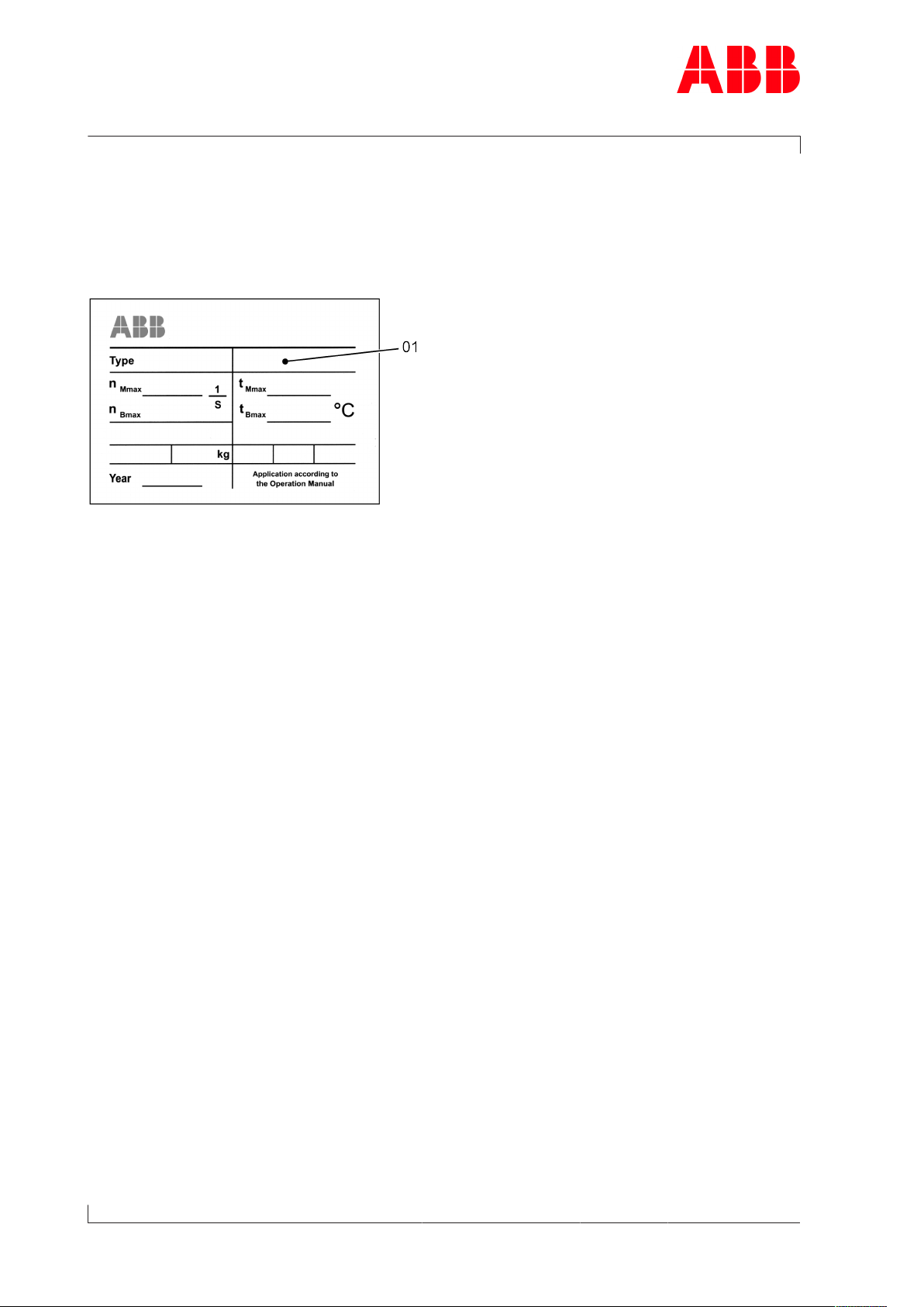
Fig.1: Serial number (01) on the rating plate
This Operation Manual belongs to the turbocharger with the identical serial number (01), see
chapter 3 (Safety data sheet) and the rating plate on the turbocharger.
Operation Manual
The Operation Manual explains the turbocharger and contains instructions for safe opera-
Page 2 / 7
tion.
The Operation Manual is a complement to and expansion of existing national regulations for
occupational safety, accident prevention and environmental protection.
Target group
The Operation Manual is aimed at engineers and trained mechanics responsible for the
proper operation of the engine and for the turbocharger connected to it.
Availability of the Operation Manual
The Operation Manual must be available where the turbocharger is used.
All persons operating or working on the turbocharger must have read and fully understood
the Operation Manual.
© Copyright 2017 ABB. All rights reserved. HZTL4005_EN Revision F May 2017
Page 5

Operation Manual / 1 Introduction
1 Introduction / 1.2 Symbols, definitions
1.2 Symbols, definitions
Symbols
The following symbols are used in this document:
u Indicates an action step.
1. Indicates a numbered action step.
→ Refers to a page number.
Definition of Note
NOTICE
Note
The note provides advice which facilitates the work.
Definition of mandatory signs
Mandatory signs show the protective equipment to be worn for a task. The mandatory signs
are described in chapter Safety and must be complied with.
Definition of Caution / Warning
Caution and warning signs are described in chapter Safety.
ABB Turbo Systems
ABB Turbo Systems Ltd is identified as ABB Turbo Systems in this document.
Official service stations of ABB Turbo Systems
Official service stations are identified in this document as ABB Turbocharging Service Stations. They are regularly audited and certified by ABB Turbo Systems. Also see chapter Con-
tact information →7.
Page 3 / 7
© Copyright 2017 ABB. All rights reserved. HZTL4005_EN Revision F May 2017
Page 6

Operation Manual / 1 Introduction
1 Introduction / 1.2 Symbols, definitions
Definition of pictograms
The following pictograms can occur in this document. These point out actions that must be
taken in accordance with the meaning of the relevant pictogram.
Pictogram Meaning Pictogram Meaning
Tighten with specified torque Affix
Tighten over specified tightening angle
Hand-tight, tighten without
tools
Oil Visually inspect
Apply screw locking paste (e.g.
Loctite)
Apply high-temperature grease See document
Apply other paste in accordance with specifications
Oil free, grease free and dry
Table1: Definition of pictograms
Measure
Note
Please note text for numbered
work step
Dispose of in an environmentally
compatible, professional way and
in compliance with locally applicable regulations
Page 4 / 7
© Copyright 2017 ABB. All rights reserved. HZTL4005_EN Revision F May 2017
Page 7
Operation Manual / 1 Introduction
1 Introduction / 1.3 Storage of new turbochargers and spare parts
1.3 Storage of new turbochargers and spare parts
Storage of new turbochargers and spare parts for up to 6 months
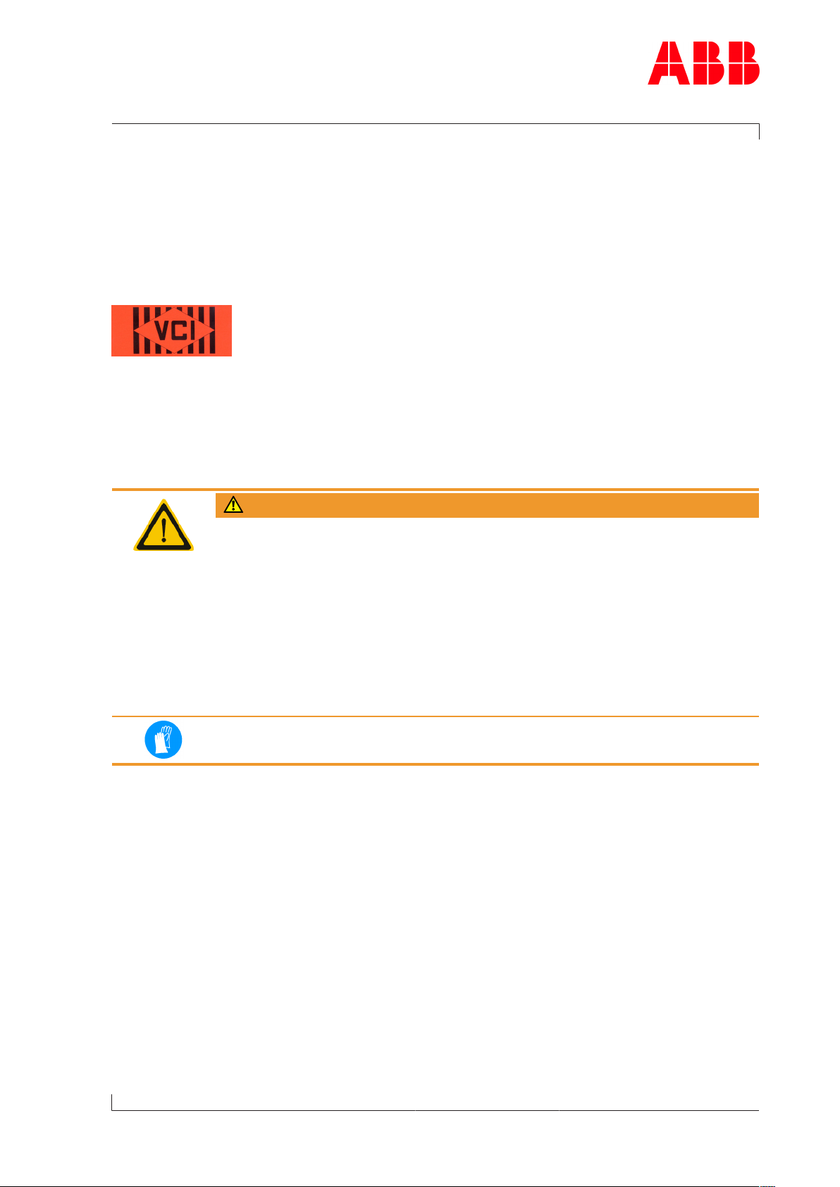
New turbochargers and spare parts can be stored in their closed packages for 6 months
from the date of delivery without additional mothballing measures, indicated by the VCI label on the package.
Fig.2: Volatile Corrosion Inhibitor (VCI)
Only dry rooms with 40...70 % atmospheric humidity, in which no water condensation can
form, are suitable as storage locations.
Storage of new turbochargers and spare parts for more than 6 months
WARNING
Health protection when handling VCI
VCI products are not hazardous in terms of the Ordinance on Hazardous
Substances. Nevertheless, the following points must be observed when
handling VCI:
u Observe information in material safety data sheet
u Ensure proper space ventilation.
u Do not eat, drink or store food at the workplace while working with VCI.
u Clean hands and face after working with VCI.
u For more information, see www.branopac.com.
Wear safety gloves to protect against mechanical hazards.
Every 6 months, the following mothballing measures are required:
u Open package.
u Remove VCI corrosion protection emitter from package and replace with a new VCI corro-
sion protection emitter of the same kind. New VCI corrosion protection emitters can be
obtained from www.branopac.com.
u Old VCI corrosion protection emitters must be disposed of in an environmentally compat-
ible, professional way and in compliance with locally applicable regulations.
Page 5 / 7
u Close package. The more tightly the package is sealed, the longer the protection dura-
tion.
© Copyright 2017 ABB. All rights reserved. HZTL4005_EN Revision F May 2017
Page 8
Operation Manual / 1 Introduction
1 Introduction / 1.3 Storage of new turbochargers and spare parts
Long-term storage of replacement turbochargers or spare parts
The turbochargers or cartridge groups will be prepared for long-term storage if requested in
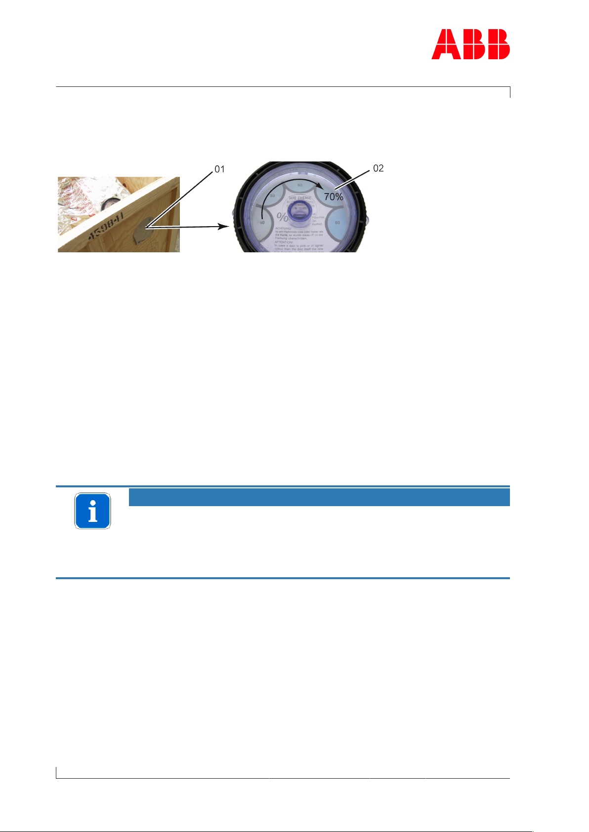
the purchase order. The package is equipped with a hygrometer (see illustration).
Fig.3: Package with hygrometer
Every 6 months, the following measures are required:
u Check the hygrometer(02) in the sight-glass. There is an opening(01) in the wooden
crate to enable you to perform this check. If the 70% indicator field has changed colour,
the maximum admissible atmospheric humidity has been exceeded. In this case, the turbocharger or cartridge group must be checked and repackaged by an ABB Turbocharging
Service Station.
u Check the package for damage. If the package is damaged, the turbocharger or cartridge
group must be checked and repackaged by an ABB Turbocharging Service Station.
After every 3 years, the following steps must be carried out by an ABB Turbocharging Service
Station:
Page 6 / 7
¡ Checking the component
¡ Replacing the desiccant
¡ Repackaging the component.
NOTICE
Replacement components which are ready for operation
If the 70% field of the hygrometer(02) has not changed colour and the package is not damaged, the replacement turbocharger or replacement cartridge
group can be put into operation without previously having been checked by
an ABB Turbocharging Service Station.
Unpackaging replacement turbochargers or spare parts
Once the material has been unpackaged from the VCI package, the corrosion protection is
no longer effective.
To prevent condensation, the temperature of the package contents must be the same as the
ambient temperature.
© Copyright 2017 ABB. All rights reserved. HZTL4005_EN Revision F May 2017
Page 9

Operation Manual / 1 Introduction
1 Introduction / 1.4 Contact information
1.4 Contact information
Contact information for the ABB Turbocharging Service Stations is available online.
u Scan the QR code to access our website.
ABB Turbo Systems Ltd
Bruggerstrasse 71a
CH-5401 Baden
Switzerland
www.abb.com/turbocharging
Page 7 / 7
© Copyright 2017 ABB. All rights reserved. HZTL4005_EN Revision F May 2017
Page 10

Page 11

Operation Manual / 2 Safety / TPS-R
Table of contents
Safety
1 Safety ...................................................................................................................... 2
1.1 Introduction .................................................................................................................... 2
1.2 CE conformity................................................................................................................. 2
1.3 Definition of mandatory signs .................................................................................... 3
1.4 Definition of safety instructions ................................................................................ 3
1.5 Intended use .................................................................................................................. 4
1.6 Warning plates on the turbocharger.......................................................................... 5
1.7 Turbocharger rating plate........................................................................................... 6
1.8 Lifting of loads .............................................................................................................. 8
1.9 Prerequisites for operation and maintenance........................................................ 9
1.10 Hazards during operation and maintenance ......................................................... 10
1.11 Safe operation .............................................................................................................. 12
1.12 Safe maintenance ........................................................................................................ 13
© Copyright 2018 ABB. All rights reserved. HZTL4027_EN Revision A April 2018
Page 12

Operation Manual / 2 Safety / TPS-R
1 Safety / 1.1 Introduction
1 Safety
1.1 Introduction
Turbochargers manufactured by ABB reflect the state of the art. The respective safety and
health protection requirements are met. This ensures safe operation of the turbocharger.
Nevertheless, there may be some residual risks during operation of and work on the turbocharger which:
¡ Are caused by the turbocharger itself or its accessories.
¡ Are caused by the operating equipment used or supplies and materials.
¡ Are a consequence of insufficient compliance with safety instructions.
¡ Are a consequence of insufficient or inappropriate performance of maintenance and in-
spection work.
The operating company is responsible for defining measures that regulate safe access to
and safe handling of the turbocharger.
Page 2 / 16
All instructions contained in this chapter must be observed for safe and trouble-free operation of the turbocharger and during all work on the turbocharger.
All further safety instructions contained and specifically identified in every chapter of this
manual (Definition of safety instructions →3) must also be observed.
1.2 CE conformity
Information
ABB turbochargers comply with the Machinery Directive 2006/42/EC and are partly completed machinery as defined by Article 2 g in this directive.
© Copyright 2018 ABB. All rights reserved. HZTL4027_EN Revision A April 2018
Page 13
Operation Manual / 2 Safety / TPS-R
1 Safety / 1.3 Definition of mandatory signs
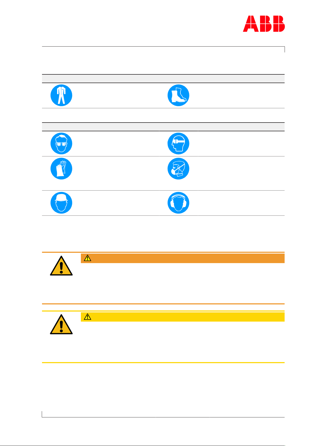
1.3 Definition of mandatory signs
To be worn at all times
Protective clothing Safety footwear to protect
against mechanical hazard and
risk of falling
Table1: Personal protective equipment to be worn at all times
To be worn specific to the respective task
Safety glasses Safety goggles
Safety gloves to protect
against
- Mechanical hazard
- Chemical hazard
- Thermal hazard
- Electrical hazard
Safety helmet Ear protection
Table2: Personal protective equipment to be worn specific to the respective task
Respiratory mask to protect
against
- Dusts
- Gases
1.4 Definition of safety instructions
WARNING
Definition of Warning
Non-compliance or inaccurate compliance with working or operating instructions indicated by this symbol and the word WARNING can lead to serious injuries to personnel and even to fatal accidents.
u Warning signs must always be observed.
Page 3 / 16
CAUTION
Definition of Caution
Non-compliance or inaccurate compliance with working or operating instructions indicated by this symbol and the word CAUTION can lead to serious damage to engine or property with grave consequences.
u Caution signs must always be observed.
© Copyright 2018 ABB. All rights reserved. HZTL4027_EN Revision A April 2018
Page 14
Operation Manual / 2 Safety / TPS-R
1 Safety / 1.5 Intended use
1.5 Intended use
Use on internal combustion engines in general
ABB turbochargers are intended for charging internal combustion engines.
The turbocharger supplies the engine with the air volume or air/gas mixture and the associated charging pressure required for operation.
The turbocharger is solely intended to be operated with a clockwise direction of rotation as
viewed from the turbine end.
The specific operating limits of the turbocharger were determined on the basis of information from the enginebuilder about the intended use. These data are given on the rating
plate.
ABB accepts no liability and rejects all warranty claims for any non-intended uses.
WARNING
Unapproved operation
Any operation of the turbocharger outside of its operating limits can be hazardous to personnel.
u Only operate the turbocharger within the operating limits.
u Only trained personnel must operate the turbocharger.
Page 4 / 16
The intended use of the turbocharger includes compliance with all regulations and conditions. In particular, the following must be observed:
¡ Operation Manual
¡ Instructions of the enginebuilder
State of the art
The turbocharger is designed and manufactured according to the state of the art and is safe
to operate.
Perfect condition
The turbocharger must only be used when it is in a technically flawless condition and operated in compliance with its intended use.
ABB excludes any liability for damage resulting from unauthorized modifications to the turbocharger or improper operation.
© Copyright 2018 ABB. All rights reserved. HZTL4027_EN Revision A April 2018
Page 15
Operation Manual / 2 Safety / TPS-R
1 Safety / 1.6 Warning plates on the turbocharger
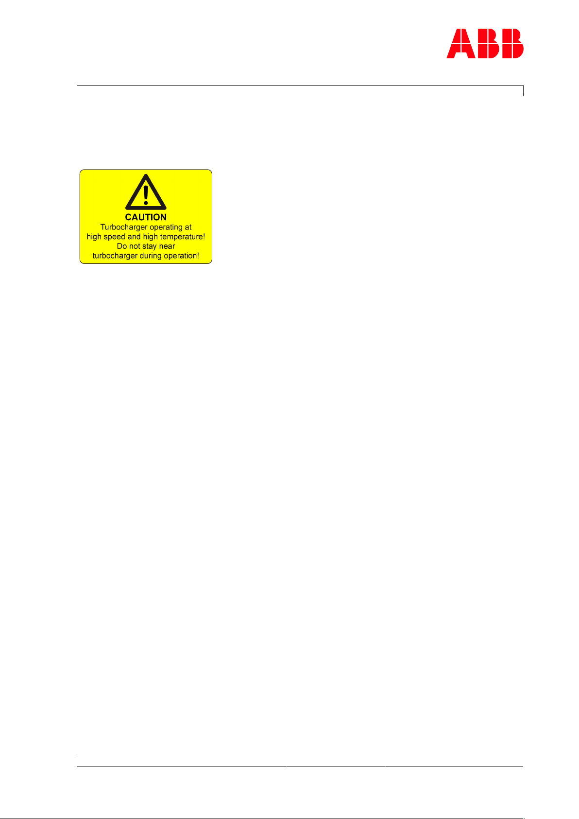
1.6 Warning plates on the turbocharger
Warning plates are attached to the turbocharger, which must be observed. The warning
plates must always be present in the intended locations and must be legible.
Fig.1: Warning plate
If warning plates are not present in the intended locations or are not legible, they must be
replaced with new warning plates. The necessary information can be found in the Operation
Manual, Chapter 4 Product description.
Turbochargers supplied to the enginebuilder without insulation must be equipped later with
warning plates on the insulation. This is the responsibility of the enginebuilder.
Page 5 / 16
© Copyright 2018 ABB. All rights reserved. HZTL4027_EN Revision A April 2018
Page 16
Operation Manual / 2 Safety / TPS-R
1 Safety / 1.7 Turbocharger rating plate
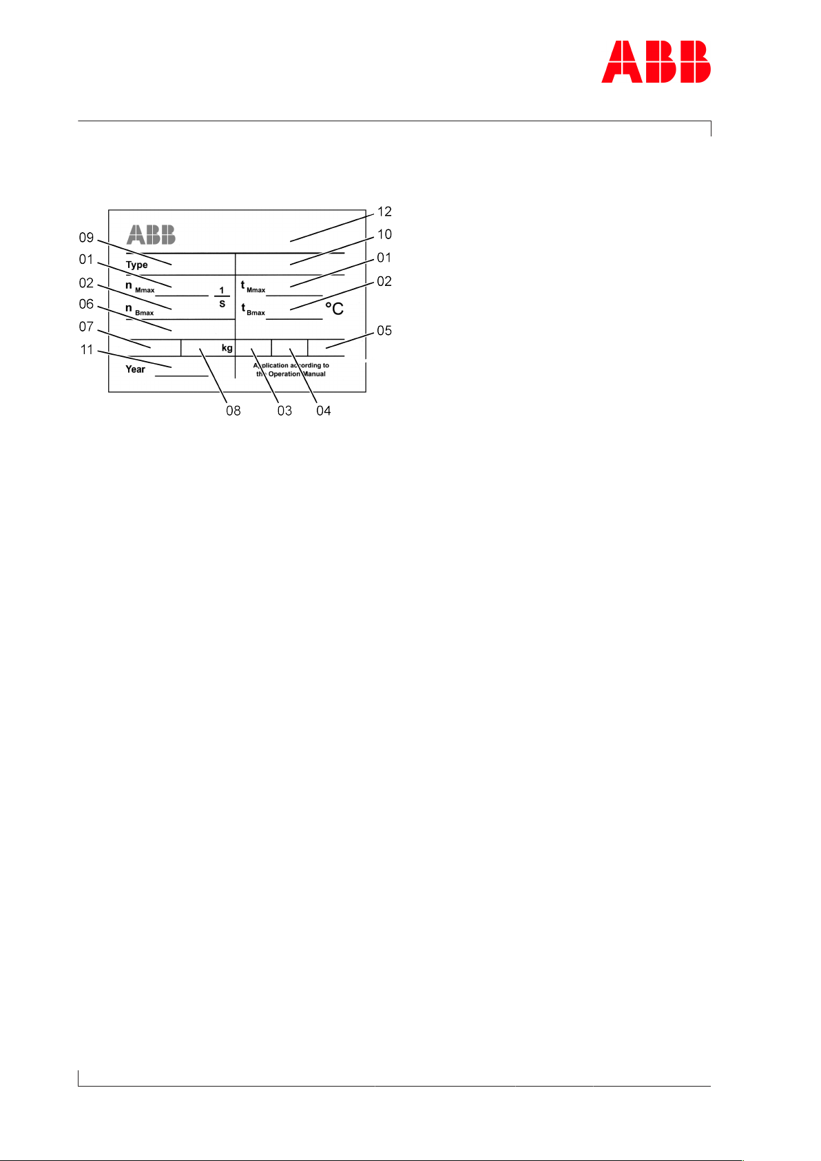
1.7 Turbocharger rating plate
Fig.2: Rating plate
Page 6 / 16
Operating limits
01 Turbocharger operating limits at engine overload (110%).
In test rig operation only, unless otherwise agreed with the enginebuilder.
02 Turbocharger operating limits during operation
Recommended inspection and replacement intervals of turbocharger components
03 Inspection interval of plain bearings in 1000h
04 Replacement interval of compressor in 1000h
05 Replacement interval of turbine in 1000h
Further data
06 Customer part number
07 Designation for special design
08 Weight of turbocharger in kg
09 Turbocharger type
10 Serial number
11 Year of construction of turbocharger
12 Manufacturing plant
© Copyright 2018 ABB. All rights reserved. HZTL4027_EN Revision A April 2018
Page 17

Operation Manual / 2 Safety / TPS-R
1 Safety / 1.7 Turbocharger rating plate
Explanations regarding the rating plate
The recommended inspection and replacement intervals and the corresponding operating
limits are jointly defined with the enginebuilder. This information is specific to the system.
Operation above the indicated values n
Bmax
, t
can considerably shorten the recommended
Bmax
replacement intervals. In such a case, we recommend that you contact the nearest official
service station of ABB Turbo Systems.
n
, t
Mmax
normally apply only when running at overload (110%) during trials on the engine
Mmax
test bed. These limit values can also be permitted during operation for special applications.
Operation above n
Mmax
and t
is not permitted.
Mmax
Non-observance of the recommended inspection and replacement intervals increases the
risk of unpredictable component failures.
Locations of the rating plates
The locations of the rating plates are defined in the Operation Manual, Chapter 4 Product
description.
Page 7 / 16
© Copyright 2018 ABB. All rights reserved. HZTL4027_EN Revision A April 2018
Page 18
Operation Manual / 2 Safety / TPS-R
1 Safety / 1.8 Lifting of loads
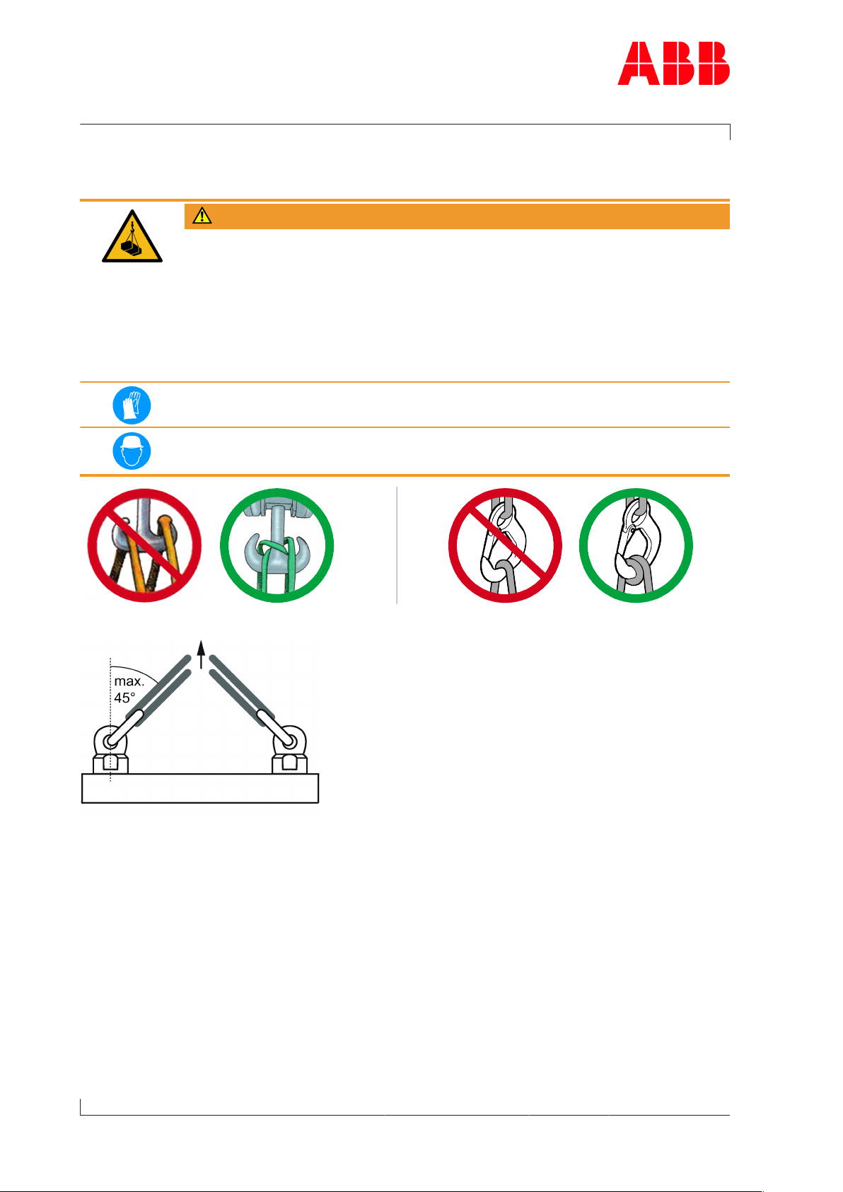
1.8 Lifting of loads
WARNING
Suspended loads
Loads that are not attached according to regulations can cause injury to
personnel or fatal accidents.
u Loads must always be fastened to properly functional lifting gear with a
sufficient load limit.
u Pay attention to the correct attachment of loads on the crane hook.
u People must not stand beneath suspended loads.
Wear safety gloves to protect against mechanical hazards.
Wear safety helmet.
Page 8 / 16
Fig.3: Attachment of loads on the crane hook
Fig.4: Attachment angle
If there are two or more suspension points, the attachment angle of 45° must not be exceeded. This prevents excessive loading due to diagonal pull.
u Before looping around the components of the turbocharger, let them cool down (max-
imum 80°C).
u Attach components of the turbocharger as described in the respective action steps.
u Use a suitable edge guard if there are sharp edges.
u The assembly devices must be completely screwed in and must not unscrew during use.
u Use assembly devices only for the described applications.
u Put down dismantled components of the turbocharger in such a way that they cannot tip
over.
© Copyright 2018 ABB. All rights reserved. HZTL4027_EN Revision A April 2018
Page 19
Operation Manual / 2 Safety / TPS-R
1 Safety / 1.9 Prerequisites for operation and maintenance
1.9 Prerequisites for operation and maintenance
Responsibility of the operating company
In awareness of its responsibility, the operating company must ensure that only authorised
personnel work on the turbocharger, who:
¡ Are versed in the general and locally applicable regulations for occupational safety and
accident prevention
¡ Are equipped with the prescribed personal protective equipment
¡ Have read and understood the Operation Manual
¡ Have been instructed in the use of the turbocharger.
The safety-conscious work of the personnel and adherence to the Operation Manual must be
checked periodically.
Suitable working materials and personal protective equipment must be kept in a perfect
condition.
Only authorised personnel may remain in the vicinity of the turbocharger when the engine is
running.
Competence of personnel
The turbocharger must only be operated and serviced by trained and authorised personnel.
Basic mechanical training is a prerequisite.
Modifications to the turbocharger
Modifications to the turbocharger must be approved by ABB Turbo Systems.
WARNING
Use original parts
Operation of the turbocharger with non-original parts can impair the safety
of the turbocharger and can cause serious damage to property and injury to
personnel.
u Only use original parts from ABB.
Original parts and accessories are specially designed for ABB turbochargers.
ABB accepts no liability for any damage resulting from the use of non-original parts and corresponding accessories.
Page 9 / 16
© Copyright 2018 ABB. All rights reserved. HZTL4027_EN Revision A April 2018
Page 20

Operation Manual / 2 Safety / TPS-R
1 Safety / 1.10 Hazards during operation and maintenance
1.10 Hazards during operation and maintenance
Noise hazards
The turbocharger's noise emission is influenced by its installation and operating conditions.
A noise level exceeding 85 dB(A) is harmful.
WARNING
Danger due to noise
Exposure to noise can harm the hearing system, impair health and the psychological state and may lead to lack of attention and irritation.
u When the engine is running, always wear ear protection.
u Always wear ear protection if the sound pressure level exceeds 85 dB(A).
Wear ear protection.
Page 10 / 16
Hazards due to hot surfaces
Surfaces of the turbocharger, attached parts and operating fluids (lubricating oil) get hot
during operation. The surface temperature depends on the efficacy of the existing insulation. The temperature may rise to a level that can cause burns.
WARNING
Danger of burns
Touching hot surfaces or contact with hot operating fluids can cause burns.
u Do not touch hot surfaces. Observe the warning plate on the turbochar-
ger.
u Wear heat-resistant safety gloves and protective clothing.
u Wait for the turbocharger to cool down before carrying out any work.
Wear safety gloves to protect against thermal hazards.
© Copyright 2018 ABB. All rights reserved. HZTL4027_EN Revision A April 2018
Page 21
Operation Manual / 2 Safety / TPS-R
1 Safety / 1.10 Hazards during operation and maintenance
WARNING
Hot surfaces on a non-insulated turbocharger
Non-insulated turbochargers can cause serious injuries to personnel (burns).
The turbocharger is supplied with or without insulation in accordance with
the purchase order received from the enginebuilder. If supply is without insulation, the enginebuilder is responsible for providing the turbocharger
with proper insulation and for providing protection against contact with hot
surfaces.
u Compliance with the instructions and specifications given by the en-
ginebuilder to protect against hot turbocharger surfaces is compulsory.
Wear safety gloves to protect against thermal hazards.
Hazards due to rotating parts
WARNING
Physical hazards
Contact with rotating parts can cause severe injury. The turbocharger must
never be used without the filter silencer or the air suction branch. With the
engine stopped, the rotor can rotate due to the stack draught alone.
u Operate the turbocharger in compliance with the specifications.
u Secure the rotor against unintentional rotation during maintenance.
Wear safety gloves to protect against mechanical hazards.
Page 11 / 16
© Copyright 2018 ABB. All rights reserved. HZTL4027_EN Revision A April 2018
Page 22

Operation Manual / 2 Safety / TPS-R
1 Safety / 1.11 Safe operation
1.11 Safe operation
Mechanical hazards during operation
During standard operation, no mechanical hazards are caused by the turbocharger itself if it
has been properly installed.
Safety during commissioning and operation
u Visually inspect your working environment before starting work.
u Remove any obstacles and objects littering the workplace.
u Check all pipes to and from the turbocharger for damage and leaks before commission-
ing.
u Check turbocharger for recognisable damage or defects every 12 hours of operation or at
least once a day.
u Report any damage and any alterations of operational characteristics to the responsible
department immediately.
Page 12 / 16
u In case of damage, take the turbocharger out of operation immediately and safeguard
against accidental/unauthorised use.
u When switching on operating energy supplies (hydraulics, pneumatics, electricity), pay at-
tention to the risks that may occur as a consequence of this energy input.
© Copyright 2018 ABB. All rights reserved. HZTL4027_EN Revision A April 2018
Page 23

Operation Manual / 2 Safety / TPS-R
1 Safety / 1.12 Safe maintenance
1.12 Safe maintenance
Occupational safety
WARNING
Injuries to persons
Severe injuries to personnel or fatal accidents can be caused by mechanical
influences as a consequence of hazardous and inadequate operational procedures or non-compliance with safety and health standards.
u When working on the turbocharger always wear safety footwear and pro-
tective clothing to protect against mechanical hazards.
u Keep personal protective equipment in perfect condition.
u Obey mandatory signs.
u Observe the general rules for occupational safety and prevention of acci-
dents.
u Only perform operations that are described in this manual.
u Only perform operations for which you have received instruction or train-
ing.
Wear safety footwear to protect against mechanical hazard and risk of falling.
Wear protective clothing.
WARNING
Risk of falling
When working on the turbocharger, there is a risk of falling.
u Do not climb onto the turbocharger or onto attached parts and do not
use them as climbing aids.
u Use suitable climbing aids and working platforms for work above body
height.
u Comply with the general accident prevention regulations.
u Only perform work on the turbocharger when you are in a physically and psychologically
stable condition.
u Only work with suitable tools, equipment and appliances that function properly.
u Power tools must be grounded and cables must be undamaged.
u Keep the workplace clean; clear away any loose objects and obstacles on the floor.
Page 13 / 16
u Keep the floor, equipment, and turbocharger clean.
u Have oil binding agents ready and provide or keep oil pans at hand.
u Clean up any spills.
u Have fire protection means and extinguishing agents available.
© Copyright 2018 ABB. All rights reserved. HZTL4027_EN Revision A April 2018
Page 24

Operation Manual / 2 Safety / TPS-R
1 Safety / 1.12 Safe maintenance
Use of assembly devices
Assembly devices are specially constructed and designed for the defined use; they are not
commercially available products.
u Use assembly devices only for the described applications.
Welding work in the vicinity of the turbocharger
u When performing welding work in the vicinity of the turbocharger, always cover the filter
silencer to prevent the filter mat from being damaged.
u Keep flammable objects and substances out of the vicinity of flying sparks.
u Cover all connections on the turbocharger so that no foreign objects can enter the tur-
bocharger.
u Wear personal protective equipment (PPE) for welding operations.
Safety during cleaning
Page 14 / 16
If cleaning agents or solvents are used for cleaning, the corresponding material safety data
sheet and the safety instructions in section Hazards due to operating materials and supplies
must be observed.
u Observe the material safety data sheet for the cleaning agent or solvent.
u Wear personal protective equipment (PPE) according to the material safety data sheet.
u Inspect the electric cables for abrasion and damage before and after your cleaning work.
Safety during disassembly, assembly, maintenance and repair
u Observe the procedures for set-up, service and inspection work and the inspection inter-
vals.
u Inform the operating staff before starting any service or repair work. Make sure the en-
gine is not started while work is being conducted on the turbocharger.
u Before taking off any cover or removing any guard from the turbocharger, switch off the
engine and wait until the turbocharger has come to a standstill.
u Make sure that the oil supply is interrupted, especially with an external oil supply.
u Only restart the engine after all parts have been properly fitted again and oil supply is en-
sured.
CAUTION
Mechanical operations on the turbocharger
Components of the turbocharger can be damaged or destroyed as a result
of improper procedures.
u Only perform operations that are described in this chapter.
u Only perform operations for which you have received instruction or train-
ing.
© Copyright 2018 ABB. All rights reserved. HZTL4027_EN Revision A April 2018
Page 25

Operation Manual / 2 Safety / TPS-R
1 Safety / 1.12 Safe maintenance
Safety when taking out of operation or preparing for mothballing
u Secure rotor against turning. The rotor can rotate due to the stack draught alone.
u Observe the material safety data sheet for the cleaning and mothballing agents.
u Wear personal protective equipment (PPE) according to the material safety data sheet.
Mechanical hazards when working on the turbocharger
WARNING
Physical hazards due to rotating parts
The rotor can rotate due to the stack draught alone. Contact with rotating
parts can cause severe injury.
u Secure rotor against turning.
WARNING
Mechanical hazard
Severe injuries to personnel or fatal accidents can be caused by mechanical
influences as a consequence of hazardous and inadequate operational procedures.
u Observe the general rules for occupational safety and prevention of acci-
dents.
u Ensure workplace safety.
u Only perform operations that are described in this chapter.
u Only perform operations for which you have previously received instruc-
tion or training.
Page 15 / 16
© Copyright 2018 ABB. All rights reserved. HZTL4027_EN Revision A April 2018
Page 26
Operation Manual / 2 Safety / TPS-R
1 Safety / 1.12 Safe maintenance
Hazards due to operating materials and supplies
Operating materials and supplies are substances required for the operation of the turbocharger or for the performance of maintenance work. Oils, greases, coolants, detergents
and solvents, acids and similar substances can be classified as hazardous substances.
WARNING
Handling operating materials and supplies
Swallowing or inhaling vapours of operating materials and supplies or contact with them may be harmful to health.
u Do not breathe in these substances and avoid contact with the skin.
u Ensure proper ventilation.
u Observe the information in the material safety data sheet for the operat-
ing materials and supplies.
u Wear personal protective equipment (PPE) according to the material
safety data sheet.
u Comply with local legislation.
Page 16 / 16
Wear safety goggles.
Wear safety gloves to protect against chemical hazards.
Wear a respiratory mask to protect against gases.
WARNING
Danger of fire or explosion
Flammable and combustible operating materials and supplies can catch fire
or resulting vapours can lead to an explosion.
u Observe the information in the material safety data sheet for the operat-
ing materials and supplies.
u Comply with local legislation.
u Do not allow any exposed flame or ignition source during cleaning work.
u Carry out cleaning in the open or provide sufficient ventilation.
CAUTION
Environmental hazard
Improper handling of operating materials and supplies can lead to environmental damage.
u Observe the information in the material safety data sheet for the operat-
ing materials and supplies.
u Comply with local legislation.
© Copyright 2018 ABB. All rights reserved. HZTL4027_EN Revision A April 2018
Page 27

Operation Manual / TPS61-R / Safety data sheet
Safety data sheet
TPS61-R HT591545
TPS61-R HT591545
Page 1 / 1
511 650
511 620
TPS61R35-162850A
720 12 50 50
2019
© Copyright 2019 ABB. All rights reserved. HT591545 October 2019
Page 28

Page 29

Operation Manual / 4 Product description / TPS61-R
Table of contents
Product description
1 Introduction............................................................................................................ 3
1.1 Essential information.................................................................................................... 3
1.2 Registered trademarks................................................................................................. 3
1.3 Related documents........................................................................................................ 3
1.4 Layout and function of the turbocharger ................................................................ 4
1.5 Locations of the rating plates..................................................................................... 5
1.6 Warning plates on the turbocharger......................................................................... 6
2 Removing and Installing........................................................................................ 7
2.1 Turbocharger weight and transportation ................................................................ 7
2.2 Removing the turbocharger........................................................................................ 8
2.3 Installing the turbocharger......................................................................................... 9
3 Commissioning ..................................................................................................... 11
3.1 Oil supply ....................................................................................................................... 11
3.2 Inspection procedures................................................................................................ 12
3.3 Commissioning after taking out of operation....................................................... 14
4 Monitoring operation .......................................................................................... 15
4.1 Oil pressure, oil temperature..................................................................................... 15
4.2 Exhaust gas temperature before turbine ............................................................... 18
4.3 Turbocharger speed.................................................................................................... 18
5 Operation and service ......................................................................................... 21
5.1 Noise emission ............................................................................................................. 21
5.2 Service work .................................................................................................................. 23
5.3 Expected replacement intervals .............................................................................. 26
6 Stopping the engine ............................................................................................ 27
7 Eliminating malfunctions.................................................................................... 28
7.1 Malfunctions when starting...................................................................................... 28
7.2 Malfunctions during operation ................................................................................ 28
7.3 Turbocharger is surging ............................................................................................. 32
7.4 Malfunctions when stopping.................................................................................... 33
7.5 Speed measurement system .................................................................................... 33
8 Mothballing the turbocharger............................................................................ 35
8.1 Taking the engine out of operation for up to 12months ................................... 35
8.2 Taking the engine out of operation for more than 12months .......................... 36
9 Disposing of turbocharger components .......................................................... 37
© Copyright 2019 ABB. All rights reserved. HZTL4042_EN Rev.B June 2019
Page 30

Operation Manual / 4 Product description / TPS61-R
Table of contents
10 Spare parts ........................................................................................................... 38
10.1 Ordering spare parts.................................................................................................. 38
10.2 Spare parts of the speed measurement system .................................................. 38
Figures................................................................................................................... 39
Tables .................................................................................................................... 40
© Copyright 2019 ABB. All rights reserved. HZTL4042_EN Rev.B June 2019
Page 31

Operation Manual / 4 Product description / TPS61-R
1 Introduction / 1.1 Essential information
1 Introduction
1.1 Essential information
Design variants
This document is valid for different design variants of turbochargers. There may be sections
and descriptions of components that are not relevant for a specific turbocharger variant.
Please contact an ABB Turbocharging Service Station if you have any questions regarding a
design variant (see Contact information at www.abb.com/turbocharging).
Accuracy of illustrations
The illustrations in this document are general in nature and intended for ease of understanding. Differences in detail are therefore possible.
1.2 Registered trademarks
The trademarks of outside companies are used in this document. These are marked with the
® symbol.
1.3 Related documents
Chapter Document number
Operation Manual / 1 Introduction HZTL4005
Operation Manual / 2 Safety HZTL4027
Operation Manual / 3 Safety data sheet *) Serial number of the turbocharger
Table1: Related documents
*) This chapter is only present in serialised operation manuals.
Page 3 / 40
© Copyright 2019 ABB. All rights reserved. HZTL4042_EN Rev.B June 2019
Page 32

Operation Manual / 4 Product description / TPS61-R
1 Introduction / 1.4 Layout and function of the turbocharger
1.4 Layout and function of the turbocharger
Page 4 / 40
Fig.1: Layout and function of TPS61-R
01 Air suction branch 06 Plain bearing bush
02 Compressor casing 07 Turbine
03 Diffuser 08 Turbine casing
04 Bearing casing 09 Nozzle ring
05 Axial thrust bearing 10 Compressor wheel
© Copyright 2019 ABB. All rights reserved. HZTL4042_EN Rev.B June 2019
Page 33

Operation Manual / 4 Product description / TPS61-R
1 Introduction / 1.5 Locations of the rating plates
Mode of operation
The turbocharger is a turbomachine and consists of the following main components:
¡ Turbine
¡ Compressor.
These components are installed on a common shaft and form the rotor (see Fig.1: Layout
and function of TPS61-R →4).
The exhaust gases of the internal combustion engine flow through the turbine casing(08)
and the nozzle ring(09) onto the turbine(07). The turbine(07) uses the energy contained in
the exhaust gas to drive the rotor and thus the compressor wheel(10). The exhaust gases
then reach the atmosphere through the exhaust gas pipe connected to the turbine casing.
The compressor wheel(10) sucks in air through the air suction branch(01). In the compressor wheel(10), the energy required for building up the pressure is transferred to the air.
By flowing through the diffuser(03) and the compressor casing(02), the air is compressed
further and is then directed to the engine cylinders.
The rotor runs in two radial plain bearing bushes(06) which are located in the bearing casing(04) between the compressor and turbine. The axial thrust bearing(05) is located in
front of the two radial plain bearing bushes.
The bearings are connected to a central lubricating oil duct which is normally supplied by the
lubricating oil circuit of the engine. The oil outlet lies at the deepest point of the bearing casing(04).
1.5 Locations of the rating plates
Page 5 / 40
Fig.2: Locations of the rating plates
One rating plate (01) each is attached on the left and the right side of the turbocharger bearing casing.
Explanations regarding the rating plate can be found in the chapter dealing with safety.
© Copyright 2019 ABB. All rights reserved. HZTL4042_EN Rev.B June 2019
Page 34
Operation Manual / 4 Product description / TPS61-R
1 Introduction / 1.6 Warning plates on the turbocharger
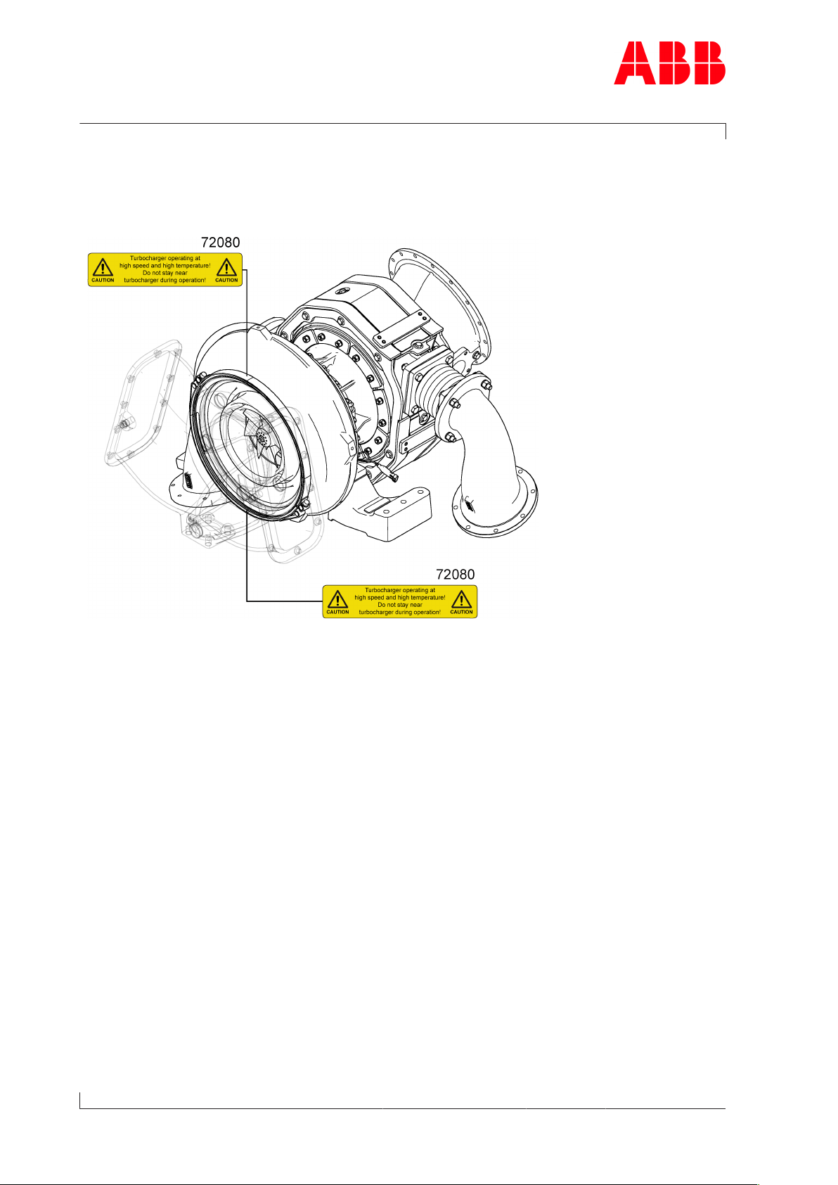
1.6 Warning plates on the turbocharger
Warning plates are affixed at the following locations:
Page 6 / 40
Fig.3: Warning plates on the turbocharger
ABB does not supply insulation for this turbocharger. If the turbocharger is insulated at a
later date and warning plates are covered, the warning signs must be attached to the insulation. This is the responsibility of the enginebuilder.
If warning plates are not present in the designated locations or not readable, proceed as follows:
u Order new warning plates (72080) from ABB Turbocharging Service Stations (see chapter
Ordering spare parts →38).
u Remove any warning plates that have become unreadable.
u Clean and degrease the areas designated for the warning plates.
u Fit new warning plates and remove protective sheets.
© Copyright 2019 ABB. All rights reserved. HZTL4042_EN Rev.B June 2019
Page 35

Operation Manual / 4 Product description / TPS61-R
2 Removing and Installing / 2.1 Turbocharger weight and transportation
2 Removing and Installing
2.1 Turbocharger weight and transportation
Lifting gear with a sufficient load limit must be used for removing and installing the turbocharger. The following weight specification applies to the heaviest variant possible. Depending on the specification, the weight specified on the rating plate may be lower than the
standard value specified here.
CAUTION
Damage to bellows
The turbochargers are supplied without fitted pipe sections and bellows.
The parts are delivered separately, because they can be damaged or destroyed during turbocharger transport if they are fitted.
u Never transport turbocharger with bellows fitted.
Fig.4: Turbocharger transport
Product Weights [kg]
TPS61-R 720
Table2: Weight of the turbocharger
Page 7 / 40
© Copyright 2019 ABB. All rights reserved. HZTL4042_EN Rev.B June 2019
Page 36

Operation Manual / 4 Product description / TPS61-R
2 Removing and Installing / 2.2 Removing the turbocharger
2.2 Removing the turbocharger
WARNING
Danger of burns
Touching hot surfaces or contact with hot operating fluids can cause burns.
u Do not touch hot surfaces. Observe the warning plate on the turbochar-
ger.
u Wear heat-resistant safety gloves and protective clothing.
u Wait for the turbocharger to cool down before carrying out any work.
Wear safety gloves to protect against thermal hazards.
CAUTION
Do not strain cables
If you pull the speed measurement cables too hard, contacts can be pulled
out.
u Do not strain the speed measurement cables by pulling.
Page 8 / 40
u Disconnect all pipes according to the instructions of the enginebuilder.
u Unplug the cable connector at the speed sensor (86505).
Fig.5: Removing the turbocharger
1. Ensure that the oil connections have been dismantled.
2. Remove the bellows.
3. Attach lifting gear to the turbocharger.
4. Loosen and remove screws.
5. Lift turbocharger from engine support vertically upwards.
© Copyright 2019 ABB. All rights reserved. HZTL4042_EN Rev.B June 2019
Page 37

Operation Manual / 4 Product description / TPS61-R
2 Removing and Installing / 2.3 Installing the turbocharger
The compressor casing(72000) can be lower than the turbocharger support depending on
the casing position.
Fig.6: Putting down the turbocharger
u Put the turbocharger down onto a solid surface so that the turbocharger cannot tip over.
Support the turbocharger if necessary.
2.3 Installing the turbocharger
Requirements for the fixing screws(01)
The fixing screws(01) that are required for attaching the turbocharger bracket(02) to the
engine support(03) are not included in the ABB Turbo Systems scope of delivery. These
parts depend on the version of the engine-side bracket.
Fig.7: Requirements for fixing screws
Product Diameter
Hole in
bracket
[mm]
TPS61R
Table3: Requirements for fixing screws
Ø18 / M16 M16 ≥ 30 120 10.9 300Nm
Screw size Length
L1 [mm]
Length
L2 [mm]
Material
DIN / ISO 898
(Part 1)
Tightening
torque
Page 9 / 40
© Copyright 2019 ABB. All rights reserved. HZTL4042_EN Rev.B June 2019
Page 38

Operation Manual / 4 Product description / TPS61-R
2 Removing and Installing / 2.3 Installing the turbocharger
2.3.1 Attaching the turbocharger to the bracket
CAUTION
Damage to bellows
If the axes of the flanges of the turbine casing do not align with the piping,
the bellows can be damaged or destroyed.
u During installation of the bellows, ensure that the axes of the flanges of
the turbine casing align with the piping. If necessary, correct alignment of
the turbocharger on the engine support.
Page 10 / 40
Fig.8: Placing the turbocharger on the bracket
Product Screw position Tightening torque
(assumed friction coefficient
µ
=0.12)
TPS61-R 01 M16
300Nm
TPS61-R 02 M16
325Nm
Table4: Tightening torque for turbocharger fixing screws
1. Attach lifting gear to turbocharger and place turbocharger onto bracket.
2. Fit hexagon head screws(01) but do not tighten them yet.
3. Coat thread of hexagon-head screws(02) with high-temperature grease such as Loctite®
8009. Fit bellows with hexagon-head screws(02), Verbus Ripp® washers and nuts. Observe the tightening torque.
4. Tighten hexagon-head screws(01). Observe the tightening torque.
5. Connect the oil supply. Ensure that the connection is tight.
6. Connect cable to speed sensor(86505).
7. Remove the lifting gear.
u Connect all the gas pipes and air lines according to the enginebuilder's instructions.
© Copyright 2019 ABB. All rights reserved. HZTL4042_EN Rev.B June 2019
Page 39

Operation Manual / 4 Product description / TPS61-R
3 Commissioning / 3.1 Oil supply
3 Commissioning
3.1 Oil supply
3.1.1 Introduction
In all operating states, a functioning and carefully executed oil supply is an important prerequisite for trouble-free operation of the turbocharger.
The lubrication of the turbocharger is usually carried out with oil from the engine oil circulation.
u Comply with the enginebuilder's specifications regarding the selection of lubricating oil
and the oil change intervals.
3.1.2 Pre-lubrication
Pre-lubrication must be carried out as follows:
u Switch on the oil pump.
u Build up oil pressure &.
u Do not exceed a pre-lubrication time of 2 minutes.
u Start the engine.
u Let the oil pump run until the pump driven by the engine generates sufficient pressure.
3.1.3 Oil filtering
Filtering the lubricating oil with a filter mesh width of ≤0.034mm is sufficient for this turbocharger.
3.1.4 Oil pressure
Comply precisely with the oil pressure before the turbocharger for trouble-free operation.
The admissible values are specified in chapter Monitoring operation →15.
Page 11 / 40
© Copyright 2019 ABB. All rights reserved. HZTL4042_EN Rev.B June 2019
Page 40

Operation Manual / 4 Product description / TPS61-R
3 Commissioning / 3.2 Inspection procedures
3.2 Inspection procedures
3.2.1 Introduction
Inspection procedures include preventative visual controls, monitoring and measuring work
before and during commissioning. Inspection procedures enable changes to the turbocharger to be detected. Machine damage can be prevented.
3.2.2 Checks before commissioning
Lubricating system
CAUTION
Contaminated oil
Serious damage to engine or property can be caused by dirt and solid material particles in the oil.
u For the initial commissioning phase and after all service work, flush the
complete lubricating system with warm oil.
u Use special running-in filters when running in the engine and after all ser-
vice work on the lubricating system.
Page 12 / 40
u Check that the oil filter is clean before commissioning.
u Adhere to lubricating oil pressure at the inlet.
u Adhere to lubricating oil temperature at the inlet.
u For permissible values, see chapter Monitoring operation →15.
Warning plates
u Check whether warning plates are present and legible.
u Check whether the protective sheets have been removed.
© Copyright 2019 ABB. All rights reserved. HZTL4042_EN Rev.B June 2019
Page 41

Operation Manual / 4 Product description / TPS61-R
3 Commissioning / 3.2 Inspection procedures
3.2.3 Checks after commissioning (engine in idle mode)
Lubricating system
u Keep to the lubricating oil pressure at the inlet.
u Keep to the lubricating oil temperature at the inlet.
u Refer to chapter Monitoring operation →15 for admissible values.
Leaktightness of pipes
WARNING
Risk of burning from hot gas
Escaping gases are hot and will lead to serious burns in the event of contact.
u Check all pipes for leaks in accordance with the enginebuilder’s instruc-
tions.
3.2.4 Checks when starting up the engine
If present:
u Measure speed, oil pressure and charging pressure at various engine performances.
u Measure the exhaust gas temperature before and after the turbine.
u Measure the air temperature before and after the compressor.
u Compare the measured values with the values of the acceptance report. Different operat-
ing conditions indicate a malfunction (see chapter Eliminating malfunctions →28).
Lubricants and pastes used during assembly can liquefy or vaporise and escape as oily fluids
during the initial hours of operation. Continual escape of an oily fluid indicates an oil leak. If
there is a leak, contact an ABB Turbocharging Service Station.
Page 13 / 40
© Copyright 2019 ABB. All rights reserved. HZTL4042_EN Rev.B June 2019
Page 42

Operation Manual / 4 Product description / TPS61-R
3 Commissioning / 3.3 Commissioning after taking out of operation
3.3 Commissioning after taking out of operation
If present
u Remove cover plates (blind flanges) from the compressor casing, the gas inlet and the
gas outlet.
General
u Check the exhaust gas pipe before and after the turbine for combustion residues or wa-
ter residues and clean it. Remove any foreign objects that may be present.
u Check and clean the air supply system, and remove any foreign objects that may be
present.
u Put engine-side oil circulation to the turbocharger into operation.
u Prepare the turbocharger for operation according to section "Checks before commission-
ing".
Page 14 / 40
u The turbocharger is now ready for operation.
© Copyright 2019 ABB. All rights reserved. HZTL4042_EN Rev.B June 2019
Page 43
Operation Manual / 4 Product description / TPS61-R
4 Monitoring operation / 4.1 Oil pressure, oil temperature
4 Monitoring operation
4.1 Oil pressure, oil temperature
Lubricating oil pressure, oil inlet
To limit the oil flow rate through the turbocharger to the admissible values with the engine
at full load, an oil orifice is mandatory or already fitted at the turbocharger oil inlet if the oil
inlet pressure is > 3bar.
CAUTION
Assuring lubricating oil pressure
Serious damage to the engine or property can result from a missing or insufficient lubricating oil supply.
u The lubricating oil pressure must be monitored during operation and the
necessary pressure assured at the oil inlet.
Status for operation Pressure at oil inlet upstream of
the turbocharger
[bar] Overpressure
Normal operation 2.0< p
Engine start: Cold oil, admissible for a maximum of 15
minutes
Engine idling, admissible for a maximum of 1 hour 0.2< p
Pre-lubrication and post-lubrication (engine stopped) 0.2< p
Warning signal: (n ≥ 0.5 x n
Alarm signal: Not admissible. Stop the engine immediately. <0.2
Table5: Lubricating oil pressure at oil inlet before turbocharger
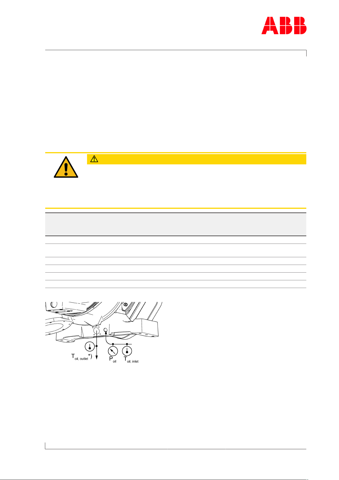
Fig.9: Arrangement of oil temperature and oil pressure measuring points
P Oil pressure measuring point
T Oil temperature measuring point
) <1.25
Bmax
oil
<8.0
oil
oil
≤4.5
≤2.5
≤1.0
Page 15 / 40
For monitoring the lubricating oil pressure, ABB Turbo Systems recommends installing a "P"
manometer immediately upstream of the turbocharger oil inlet before the orifice. If the
pressure is controlled electronically, the relevant signals should be triggered at the warning
and alarm values.
© Copyright 2019 ABB. All rights reserved. HZTL4042_EN Rev.B June 2019
Page 44
Operation Manual / 4 Product description / TPS61-R
4 Monitoring operation / 4.1 Oil pressure, oil temperature
*) If the drain pipe is vented, the lubricating oil temperature measuring point can be installed
at the outlet in the vent tank. Otherwise the measurement should be taken in the drain pipe
as close to the turbocharger as possible.
The measuring points for temperature(T) and pressure (M) in the oil supply pipe should be
attached as closely to the turbocharger as possible. No reducing installations such as orifices or valves may be attached at the engine side between the measuring point and the turbocharger oil inlet. The temperature and pressure are measured to monitor the lubrication.
Lubricating oil temperature at the inlet
CAUTION
Machine damage
If the oil temperature at the oil inlet exceeds the admissible range, this may
lead to engine damage.
u Observe oil temperature at the oil inlet according to the following table.
Page 16 / 40
Status for operation Oil temperature at the inlet
T
oil,inlet
Admissible 8…105°C
Temporarily admissible (<1h) → Alarm >105°C
Not admissible → stop engine >110°C
Not admissible → do not start engine (before start: preheat
<8°C
oil)
Table6: Lubricating oil temperature at the inlet
Lubricating oil temperature at the outlet
The oil temperature at the outlet is mainly dependant on:
¡ Lubricating oil temperature and pressure at the oil inlet
¡ Engine load and turbocharger speed
¡ Exhaust gas temperature
The maximum admissible oil temperature at the outlet is listed in the following table. The
specified oil outlet temperature is to be considered as alarm value for the turbocharger operation and must be monitored according to the current regulations.
Status for operation Oil temperature at the outlet
T
oil,outlet
Admissible ≤160°C
Temporarily admissible → alarm >160°C
Not admissible → stop engine >180°C
Admissible ≤ T
Temporarily admissible → alarm > T
Table7: Lubricating oil temperature at the outlet
oil,inlet
oil,inlet
+ 55K
+ 55K
© Copyright 2019 ABB. All rights reserved. HZTL4042_EN Rev.B June 2019
Page 45

Operation Manual / 4 Product description / TPS61-R
4 Monitoring operation / 4.1 Oil pressure, oil temperature
If the turbocharger was operated for a longer period of time outside of the admissible
range, ABB Turbo Systems recommends to have the turbocharger inspected by an ABB Turbocharging Service Station.
Page 17 / 40
© Copyright 2019 ABB. All rights reserved. HZTL4042_EN Rev.B June 2019
Page 46

Operation Manual / 4 Product description / TPS61-R
4 Monitoring operation / 4.2 Exhaust gas temperature before turbine
4.2 Exhaust gas temperature before turbine
CAUTION
Factors influencing replacement intervals
Operation above the operating limits defined on the rating plate can
shorten the recommended replacement intervals considerably.
u Measure exhaust gas temperature upstream of turbine.
u Comply with operating limits on rating plate.
u Definition and explanations concerning rating plate: refer to chapter 2 of Operation
Manual / Safety.
u Operating limits: refer to chapter 3 of Operation Manual / Safety data sheet or examine
rating plate.
4.3 Turbocharger speed
Page 18 / 40
4.3.1 Introduction
A speed measuring system enables the constant monitoring of the turbocharger speed.
CAUTION
Do not strain cables
If you pull the speed measurement cables too hard, contacts can be pulled
out.
u Do not strain the speed measurement cables by pulling.
CAUTION
Machine damage
Operation above the operating limits defined on the rating plate can
shorten the recommended replacement intervals considerably and cause
machine damage.
u Measure turbocharger speed.
u Comply with operating limits on rating plate.
u Definition and explanations concerning rating plate: refer to chapter 2 of Operation
Manual / Safety.
u Operating limits: refer to chapter 3 of Operation Manual / Safety data sheet or examine
rating plate.
If no speed measurement system is present, the system below can be ordered from an ABB
Turbocharging Service Station (see chapter Ordering spare parts →38).
© Copyright 2019 ABB. All rights reserved. HZTL4042_EN Rev.B June 2019
Page 47

Operation Manual / 4 Product description / TPS61-R
4 Monitoring operation / 4.3 Turbocharger speed
4.3.2 Layout and overview
Fig.10: Speed measurement system
86505 Speed sensor (cable not integrated)
86515 Cable connector to 86505
32109 Sealing disc
01 Screw plug
02 Gasket
4.3.3 Malfunctions on the speed measurement system
In the case of malfunctions of the speed measurement system, refer to the chapter entitled
Troubleshooting/Speed measurement system →33.
Page 19 / 40
© Copyright 2019 ABB. All rights reserved. HZTL4042_EN Rev.B June 2019
Page 48

Operation Manual / 4 Product description / TPS61-R
4 Monitoring operation / 4.3 Turbocharger speed
4.3.4 Replacing the speed sensor
WARNING
Hot speed sensor
Danger of burns. The speed sensor can reach temperatures of more than
100°C during operation.
u Wear safety gloves when disassembling the speed sensor.
Wear safety gloves to protect against thermal hazards.
The speed sensor supplied by ABB is equipped with a sealing lip and an O-ring. No additional
gasket is required during assembly.
Page 20 / 40
Fig.11: Fitting the speed sensor
Part number Tightening torque
86505 15Nm
Table8: Tightening torque(86505)
u Reduce the engine performance to idling and then stop the engine. Pay attention to post-
lubrication (Stopping the engine →27).
u Switch off the lubricating oil supply to the turbocharger.
u Disconnect cable connector (86515) from speed sensor (86505).
u Unscrew and remove defective speed sensor (86505).
u Screw in new speed sensor(86505) as far as it will go and tighten.
u Connect cable connector (86515) to speed sensor (86505).
u Switch on lubricating oil supply to the turbocharger.
© Copyright 2019 ABB. All rights reserved. HZTL4042_EN Rev.B June 2019
Page 49

Operation Manual / 4 Product description / TPS61-R
5 Operation and service / 5.1 Noise emission
5 Operation and service
5.1 Noise emission
WARNING
Danger due to noise
Exposure to noise can harm the hearing system, impair health and the psychological state and may lead to lack of attention and irritation.
u When the engine is running, always wear ear protection.
u Always wear ear protection if the sound pressure level exceeds 85 dB(A).
Wear ear protection.
The emission sound pressure level (A-weighted) is measured at a distance of 1 meter from
the turbocharger.
The highest value of the emission sound pressure level1) reaches a maximum of 105 dB(A)
near the filter silencer. The following prerequisites must be fulfilled with regard to the turbocharger to observe this limit value:
¡ Air-inlet system has been fitted
¡ All standard, noise-reducing measures2) have been fitted
¡ Bellows at the air-outlet has been acoustically insulated by the enginebuilder (see Fig.12:
Noise insulation, bellows →22).
The enginebuilder is responsible for insulating the charge air/scavenging air line and the
charge air cooler.
1) Directive 2006/42/EC, 1.7.4.2 / u / Paragraphs 5 + 7:
A-weighted emission sound pressure level
2) The enginebuilder must provide acoustically equivalent measures in case of deviating insulation versions
Page 21 / 40
© Copyright 2019 ABB. All rights reserved. HZTL4042_EN Rev.B June 2019
Page 50
Operation Manual / 4 Product description / TPS61-R
5 Operation and service / 5.1 Noise emission
Suggestion for noise insulation, bellows
Page 22 / 40
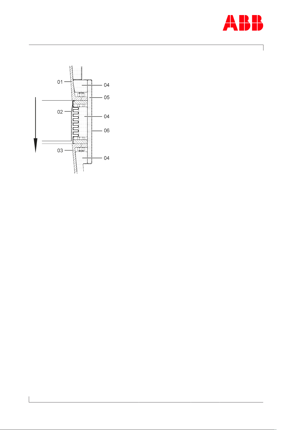
Fig.12: Noise insulation, bellows
01 Compressor casing
02 Bellows
03 Charge air duct / scavenging air duct
04 Insulation cushion
05 Insulation mat (at least 15 mm)
06 Sheet metal cover
© Copyright 2019 ABB. All rights reserved. HZTL4042_EN Rev.B June 2019
Page 51

Operation Manual / 4 Product description / TPS61-R
5 Operation and service / 5.2 Service work
5.2 Service work
Service work includes visual controls, monitoring, measuring and inspection as well as functional checks. Service work enables the detection and rectification of changes to the turbocharger and ensures full operability of the turbocharger.
CAUTION
Service intervals
Any service work on the turbocharger that is omitted or performed too late
can cause excessive contamination, wear and operating failures.
u Carry out the service work at the specified time intervals.
CAUTION
Shortened service intervals
Exceptional stresses such as several starts/stops per day, harsh environmental conditions, poor fuel quality or high system vibrations can lead to
untimely machine damage even if the prescribed service intervals are observed.
u Agree on a shortened service interval with ABB Turbo Systems.
To prevent machine damage caused by ageing and downtime, we recommend having an inspection carried out by an ABB Turbocharging Service Station no later than 5 years after the
last service.
Page 23 / 40
© Copyright 2019 ABB. All rights reserved. HZTL4042_EN Rev.B June 2019
Page 52

Operation Manual / 4 Product description / TPS61-R
5 Operation and service / 5.2 Service work
5.2.1 Service work every 24 … 48 hours
Pipes
u Check all the inlet and outlet pipes of the turbocharger for leaks.
Operating data
CAUTION
Unknown operational changes
Impairment to the degree of a possible operating failure can be the consequence.
u Have any unknown causes clarified by an ABB Turbocharging Service Sta-
tion.
Page 24 / 40
Monitoring the engine's operating data makes it possible to draw conclusions about the operating behaviour of the turbocharger.
u The following operating data and measured values must be entered every 24 … 48 hours
in the engine logbook of the enginebuilder.
¡ Performance and speed of the engine
¡ Air intake temperature
¡ Charging pressure
¡ Pressure loss in the charge air cooler
¡ Lubricating oil pressure and lubricating oil temperature.
If present:
¡ Speed of the turbocharger
¡ Pressure in air inlet system
u In case of different values, determine the cause.
5.2.2 Service work at 100 hours after commissioning
u Clean or replace the oil filter located in the supply pipe to the turbocharger while the en-
gine is stopped.
5.2.3 Service work according to instructions of enginebuilder
u Clean or replace the oil filter located in the supply pipe to the turbocharger while the en-
gine is stopped.
© Copyright 2019 ABB. All rights reserved. HZTL4042_EN Rev.B June 2019
Page 53

Operation Manual / 4 Product description / TPS61-R
5 Operation and service / 5.2 Service work
5.2.4 Service work according to data on the rating plate
WARNING
Incorrect handling of a cartridge group
The disassembly and assembly of the cartridge group, as well as the assessment of the rotor and bearing parts, requires the expertise of an ABB Turbocharging Service Station. The rotor parts rotate extremely quickly and are
sensitive to unbalance. Incorrect handling of a cartridge group can damage
the turbocharger and cause injuries to persons.
u Ensure that the disassembly and assembly of the cartridge group is only
carried out by an ABB Turbocharging Service Station.
The following service work must be carried out by an ABB Turbocharging Service Station.
¡ Dismantle turbocharger and measure clearances.
¡ Clean nozzle ring, turbine casing and compressor casing mechanically.
¡ Check nozzle ring, turbine casing and compressor casing for cracks and erosion/corro-
sion.
¡ Check and assess rotor and bearing parts.
The following work can be carried out as preparation.
u Remove the turbocharger from the engine (see chapter Removing and Installing →7).
Page 25 / 40
© Copyright 2019 ABB. All rights reserved. HZTL4042_EN Rev.B June 2019
Page 54

Operation Manual / 4 Product description / TPS61-R
5 Operation and service / 5.3 Expected replacement intervals
5.3 Expected replacement intervals
Component Operating hours
Turbine casing 25000…50000
Nozzle ring 50000
Gas outlet flange 50000
Partition wall 50000
Rotating components See rating plate information
Bearing parts 12000…24000
Other casings 50000
Table9: Expected replacement intervals [h]
1)
Page 26 / 40
1)
The recommended replacement intervals of the compressor and turbine wheels are specified with the aid of the safety concept for rotating parts (SIKO) and dependent on the
operating conditions.
Influencing parameters
The specified values are guideline values and are not guaranteed. The actual values can deviate considerably from the guideline values, for example, due to the following influences:
¡ Fuel quality and fuel treatment
¡ Load profile (thermal cycling, also number of starts/stops, emergency shutdowns, oper-
ating point)
¡ Gas inlet temperature
¡ Turbocharger specification.
¡ System-specific operating conditions (combustion quality, exhaust gas composition)
For bearing parts
¡ Lubricating oil quality (oil filtering, oil condition, oil monitoring)
¡ Load profile (speed, pressure conditions, temperature)
¡ Number of starts/stops
¡ Unbalance of the rotor (degree of contamination).
© Copyright 2019 ABB. All rights reserved. HZTL4042_EN Rev.B June 2019
Page 55

Operation Manual / 4 Product description / TPS61-R
6 Stopping the engine /
6 Stopping the engine
CAUTION
Post-lubrication
If the heat in the turbocharger is not dissipated after the engine stops, damage may result.
u Perform post-lubrication 15…20minutes after stopping the engine.
Page 27 / 40
© Copyright 2019 ABB. All rights reserved. HZTL4042_EN Rev.B June 2019
Page 56

Operation Manual / 4 Product description / TPS61-R
7 Eliminating malfunctions / 7.1 Malfunctions when starting
7 Eliminating malfunctions
7.1 Malfunctions when starting
Delayed start-up
Possible causes Remedy
Turbocharger
Table10: Malfunctions when starting – Delayed start-up
Vibrations
Turbocharger contaminated Have cleaning carried out by an ABB
Turbocharging Service Station.
Bearing damaged Contact ABB Turbocharging Service Sta-
Rotor rubbing
Foreign object in the turbocharger
tion
Page 28 / 40
Possible causes Remedy
Turbocharger
Engine Vibrations from engine Contact enginebuilder
Table11: Malfunctions when starting – Vibrations
Rotor unbalance Contact ABB Turbocharging Service
Turbine or compressor damaged
Bearing damaged
Station
Rotating parts rubbing
Normal behaviour, not a malfunction
Turbocharger
Table12: Malfunctions when starting - Rotating parts rubbing
A minimal and uniform wear on the circumference of the rotor components is
permitted. This wear can be caused by slight local rubbing against adjacent components. This causes the compressor or turbine blades to be somewhat
shortened. To prevent significant loss of efficiency, specific tolerances must be
fulfilled.
¡ If there is any doubt about the extent of the rubbing, contact an ABB Tur-
bocharging Service Station.
¡ Have a dimension check carried out by an ABB Turbocharging Service Sta-
tion.
7.2 Malfunctions during operation
Lubricating oil pressure too low
Possible causes Remedy
Turbocharger
© Copyright 2019 ABB. All rights reserved. HZTL4042_EN Rev.B June 2019
Axial clearance of the rotor excessive Contact ABB Turbocharging Service
Station
Page 57

Operation Manual / 4 Product description / TPS61-R
7 Eliminating malfunctions / 7.2 Malfunctions during operation
Possible causes Remedy
Engine Oil filter heavily contaminated Clean
Oil pump in lubricating system defective
Manometer displays incorrectly Replace manometer
Table13: Malfunctions during operation – Lubricating oil pressure too low
Check/replace
Speed reduces
Possible causes Remedy
Turbocharger
Engine Defects on the connected cylinders in
Pipes Defects, such as leaks, in the exhaust gas
Table14: Malfunctions during operation – Speed reduces
Turbine and/or nozzle ring severely contaminated
Rotor components or bearing damaged Contact ABB Turbocharging Service Sta-
pulse charging
pipes or charge air ducts
Have cleaning carried out by an ABB
Turbocharging Service Station.
tion
Contact enginebuilder
Repair
Speed increasing
Possible causes Remedy
Turbocharger
Table15: Malfunctions during operation – Speed increases
Light to medium contamination of the
turbine and/or nozzle ring
Have cleaning carried out by an ABB
Turbocharging Service Station.
Page 29 / 40
© Copyright 2019 ABB. All rights reserved. HZTL4042_EN Rev.B June 2019
Page 58

Operation Manual / 4 Product description / TPS61-R
7 Eliminating malfunctions / 7.2 Malfunctions during operation
Exhaust gas temperature too high
Engine performance and engine speed unchanged
Possible causes Remedy
Turbocharger Compressor/turbine contaminated Have cleaning carried out by an ABB
Turbocharging Service Station.
Exhaust gas back pressure too high Check the exhaust gas system.
Turbine damaged or eroded Contact ABB Turbocharging Service
Station
Air inlet system Insufficient air, for example, if the air
filter is blocked
Engine Malfunction in the injection system Repair or contact manufacturer
Charge air
cooler
Table16: Malfunctions during operation – Exhaust gas temperature too high
Cooler contaminated Clean
Cooling water volume too low Fill
Inlet temperature of cooling water too
high
Insufficient ventilation Improve ventilation
Clean or replace the air filter.
Check/clean cooling system
Page 30 / 40
Charge air pressure too low
Engine performance and engine speed unchanged, suction condition normal
Possible causes Remedy
Turbocharger
Air inlet system
Engine Air receiver not sealed Repair
Pipes Pipes downstream to the compressor
Table17: Malfunctions during operation – Charge air pressure too low
Compressor end and/or turbine end
contaminated
Compressor/turbine damaged Contact ABB Turbocharging Service Sta-
Insufficient air, for example, if the air filter is blocked
Gas piping between engine and turbine
leaking
Injection mistimed Set correctly
Valve control misadjusted
outlet not sealed.
Exhaust gas back pressure too high Check the exhaust gas system.
Have cleaning carried out by an ABB
Turbocharging Service Station.
tion
Clean or replace the air filter.
Repair.
© Copyright 2019 ABB. All rights reserved. HZTL4042_EN Rev.B June 2019
Page 59

Operation Manual / 4 Product description / TPS61-R
7 Eliminating malfunctions / 7.2 Malfunctions during operation
Charge air pressure too high
Engine performance and engine speed unchanged, suction condition normal
Possible causes Remedy
Engine Malfunction in the injection system Repair or contact manufacturer
Injection mistimed Set correctly
Engine performance higher than indicated
Table18: Malfunctions during operation – Charge air pressure too high
Check engine performance
Reduced compressor performance/efficiency and therefore engine performance
losses
CAUTION
Compressor damage
A severely contaminated or corroded compressor wheel can reduce the compressor wheel’s fatigue endurance limit and result in the turbocharger being
damaged.
u Rectify malfunction in accordance with the following table.
Possible causes Remedy
Turbocharger
Table19: Malfunctions during operation – Engine performance losses
Compressor components severely contaminated by the ventilation gases that
have been fed in
Increased blade vibration, compressor
blade damage due to the ventilation
gases that have been fed in
Material of the compressor wheel corroded due to the feeding in of ventilation
gases containing corrosive components
Material of the compressor wheel corroded due to intake air containing exhaust gases or salt
Have cleaning carried out by an ABB
Turbocharging Service Station.
Optimize oil separation
Correct the feed of ventilation gases according to instructions of enginebuilder.
Correct the feed of ventilation gases according to instructions of enginebuilder.
Prevent exhaust gas leakages in the engine space
Have cleaning carried out by an ABB Turbocharging Service Station.
Page 31 / 40
© Copyright 2019 ABB. All rights reserved. HZTL4042_EN Rev.B June 2019
Page 60
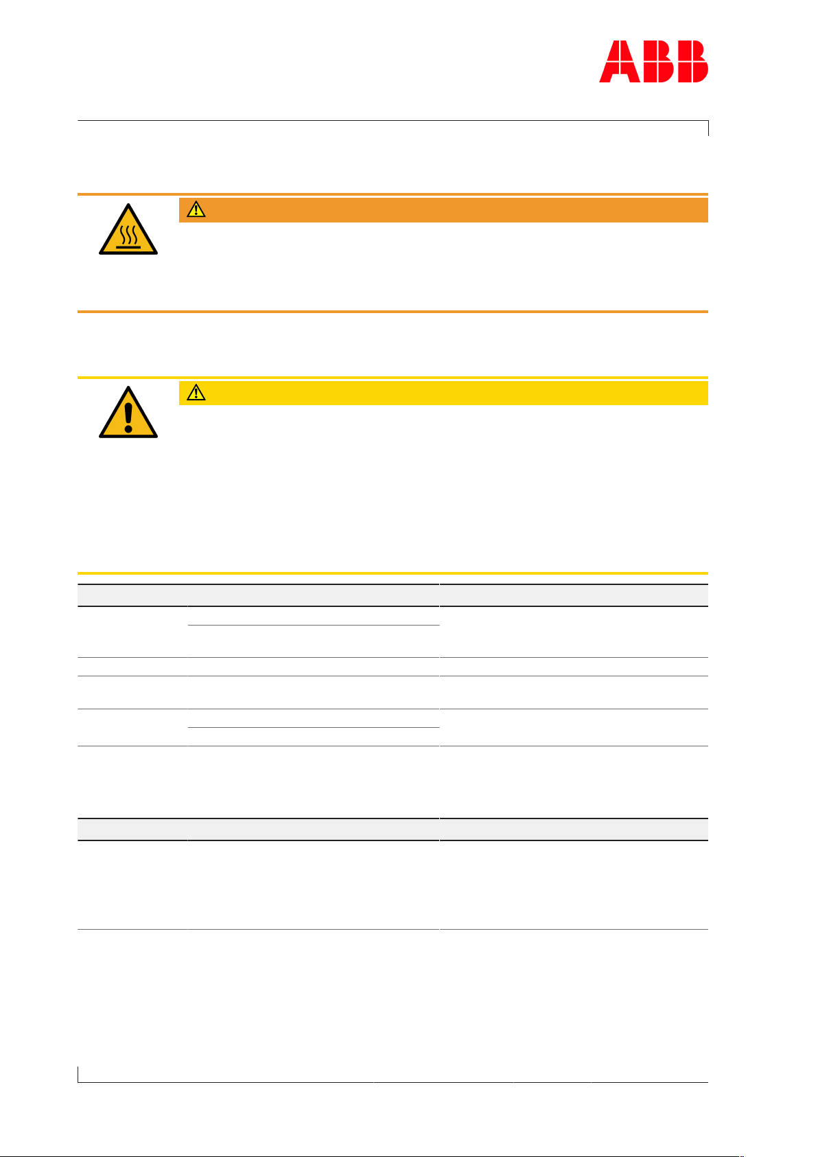
Operation Manual / 4 Product description / TPS61-R
7 Eliminating malfunctions / 7.3 Turbocharger is surging
7.3 Turbocharger is surging
WARNING
Hot air escapes from the air inlet system
A surge blow is accompanied by a loud bang and escape of hot air from the
air inlet system. This may result in injury to personnel.
u Keep a distance from the air inlet while the turbocharger is surging.
Turbocharger surges continuously or periodically
CAUTION
Continuous or periodic surging
If the turbocharger surges continuously or periodically, parts of the turbocharger may be damaged.
u Gradually reduce the engine load.
u Have the cause clarified and remedied immediately by an ABB Turbochar-
ging Service Station.
u Have parts assessed for damage and, if necessary, replaced by an ABB
Turbocharging Service Station.
Page 32 / 40
Possible causes Remedy
Turbocharger Diffuser contaminated Have cleaning carried out by an ABB
Heavy contamination deposits in the
turbine or in the nozzle ring
Air inlet system Air inlet filter contaminated Clean
Engine Protective grating in front of the tur-
bocharger contaminated or damaged
Charge air
cooler
Table20: Malfunction – Turbocharger pumping
Cooler contaminated Clean
Charge air duct blocked
Turbocharging Service Station.
Clean/replace
Sporadic surge blows
Possible causes Remedy
Engine Engine load changed quickly.
When this happens, the flow direction in the compressor is momentarily reversed. Such sporadic surge
blows do not impair the safe operation of the turbocharger.
Table21: Malfunction – Sporadic surge blows
- -
© Copyright 2019 ABB. All rights reserved. HZTL4042_EN Rev.B June 2019
Page 61

Operation Manual / 4 Product description / TPS61-R
7 Eliminating malfunctions / 7.4 Malfunctions when stopping
7.4 Malfunctions when stopping
Runout noises
Possible causes Remedy
Turbocharger
Table22: Malfunctions when stopping – Runout noises
Runout time too short
The runout time must be noted down as a reference. Because the runout time depends on
the oil viscosity, the runout time must always be measured at the same oil temperature.
Turbocharger contaminated Have cleaning carried out by an ABB Turbochar-
ging Service Station.
Bearing damaged Contact an ABB Turbocharging Service Station.
Rotor rubbing
Foreign object in the turbocharger
If the runout time is significantly shorter in comparison to a previous measurement, the following table must be observed.
Possible causes Remedy
Turbocharger
Table23: Malfunctions when stopping – Runout time too short
Turbocharger contaminated Have cleaning carried out by an ABB Turbochar-
ging Service Station.
Bearing damaged Contact an ABB Turbocharging Service Station.
Rotor rubbing
Foreign object in the turbocharger
7.5 Speed measurement system
No signal or poor signal amplitude of the speed measurement
Possible causes Remedy
Turbocharger
Table24: Malfunction of the speed measurement system – No signal or poor signal amplitude
The speed sensor was accidentally fitted with an additional gasket.
An enlarged distance
between the sensor tip and
the signal-emitting sealing
disc reduces the voltage
amplitude of the speed signal.
Sensor or cable defective Contact an ABB Turbocharging Service Station.
The screw plug for the sensor is fitted with an additional gasket (copper ring).
For information regarding the disassembly and assembly of the speed sensor, refer to chapter Re-
placing the speed sensor →20.
Install the speed sensor without the additional
gasket (copper ring).
Order new speed sensor(86505) (refer to chapter
Ordering spare parts →38).
Replacing the speed sensor →20.
Page 33 / 40
© Copyright 2019 ABB. All rights reserved. HZTL4042_EN Rev.B June 2019
Page 62

Operation Manual / 4 Product description / TPS61-R
7 Eliminating malfunctions / 7.5 Speed measurement system
Measured speed too high
Possible causes Remedy
Turbocharger
Table25: Malfunction of the speed measurement system – Measured speed too high
Sensor tip contaminated,
since it is magnetic and can
attract metallic particles.
This reduces the distance to
the signal-emitting sealing
disc, which can lead to amplification of the noise component and, hence, to false
triggering.
For information regarding the disassembly and assembly of the speed sensor, refer to chapter Re-
placing the speed sensor →20.
Dismantle the sensor, clean the sensor tip, and fit
the sensor back on with the specified tightening
torque.
Measured speed too low
Possible causes Remedy
Turbocharger
Table26: Malfunction of the speed measurement system – Measured speed too low
- - Contact ABB Turbocharging Service Station
Page 34 / 40
If none of the measures described above remedy the malfunction, have the speed measurement system checked by an ABB Turbocharging Service Station.
© Copyright 2019 ABB. All rights reserved. HZTL4042_EN Rev.B June 2019
Page 63

Operation Manual / 4 Product description / TPS61-R
8 Mothballing the turbocharger / 8.1 Taking the engine out of operation for up to 12months
8 Mothballing the turbocharger
8.1 Taking the engine out of operation for up to
12months
State of the engine lubricating oil
The turbocharger normally remains attached to the engine. The measures to be taken for
mothballing the turbocharger depend on the state of the lubricating oil. No measures are required under the following conditions:
¡ Acid number (TAN) <2mg KOH/g
¡ The engine lubricating oil is replaced by a preservative oil and circulated with the pre-lub-
rication pump before the engine is taken out of operation. Residues of old engine oil are
flushed away in this way and the bearing parts are largely protected against corrosion.
Preparations for mothballing
WARNING
Handling operating materials and supplies
Swallowing or inhaling vapours of operating materials and supplies or contact with them may be harmful to health.
u Do not breathe in these substances and avoid contact with the skin.
u Ensure proper ventilation.
u Observe the information in the material safety data sheet for the operat-
ing materials and supplies.
u Wear personal protective equipment (PPE) according to the material
safety data sheet.
u Comply with local legislation.
Wear safety goggles.
Wear safety gloves to protect against chemical hazards.
Wear a respiratory mask to protect against gases.
Page 35 / 40
If the acid number (TAN) is greater than 2mg KOH/g, the following mothballing measures
are necessary after the engine is taken out of operation:
u Remove turbocharger (see chapter Removing and Installing →7).
u Have turbocharger dismantled, cleaned, oiled and fitted again by an ABB Turbocharging
Service Station.
© Copyright 2019 ABB. All rights reserved. HZTL4042_EN Rev.B June 2019
Page 64

Operation Manual / 4 Product description / TPS61-R
8 Mothballing the turbocharger / 8.2 Taking the engine out of operation for more than 12months
8.2 Taking the engine out of operation for more than
12months
If the engine is taken out of operation, the following variants are possible with regard to the
turbocharger:
¡ Turbocharger remains attached to the engine
¡ The casings of the turbocharger remain attached to the engine, the rotor and bearing
parts are dismantled by an ABB Turbocharging Service Station and stored separately
¡ The turbocharger is completely removed, either as a whole unit or in individual parts
For the measures always necessary for preparing the turbocharger parts for mothballing,
see section Taking the engine out of operation for up to 12months, subsection Preparations
for mothballing.
If the turbocharger remains attached to the engine, see section Taking the engine out of op-
eration for up to 12months →35, subsection Rotor turning in stack draught.
Page 36 / 40
If the complete turbocharger is removed or the turbocharger is assembled again from the
individual parts:
u Seal all openings of the turbocharger with paraffin paper and wooden lids.
Only dry rooms with 40 ... 70 % atmospheric humidity, in which no water condensation can
form, are suitable as storage locations.
State of the mothballed turbocharger
u Check the turbocharger parts annually for corrosion.
u If there are signs of rust: Thoroughly clean parts and renew corrosion protection.
© Copyright 2019 ABB. All rights reserved. HZTL4042_EN Rev.B June 2019
Page 65

Operation Manual / 4 Product description / TPS61-R
9 Disposing of turbocharger components /
9 Disposing of turbocharger components
Disposal must be environmentally compatible, competent and in compliance with locally applicable regulations.
The turbocharger consists largely of metal (cast iron materials, steel, nickel-steel alloys, aluminium and bearing brass).
Further components are: Non-metallic materials (gaskets), lubricants (engine oil) and electronic parts (speed sensor and associated components).
u Dispose of metals as scrap metal for recycling.
u Dispose of non-metallic materials as waste.
u Dispose of residues of lubricants as waste oil.
u Dispose of electronic components as electronic waste.
Page 37 / 40
© Copyright 2019 ABB. All rights reserved. HZTL4042_EN Rev.B June 2019
Page 66

Operation Manual / 4 Product description / TPS61-R
10 Spare parts / 10.1 Ordering spare parts
10 Spare parts
10.1 Ordering spare parts
CAUTION
Spare part storage
All spare parts that were ordered together with the turbocharger must be
kept intact and ready for use.
u Carefully clean any rusted parts and grease them.
Please quote the following data when making queries and ordering spare parts:
¡ Turbocharger type
¡ Serial number of the turbocharger
Page 38 / 40
¡ Designation and part number
Spare parts can be ordered from any ABB Turbocharging Service Station.
u If different model variants are not taken into account in this document, contact an ABB
Turbocharging Service Station.
u Dispose of placed and unusable parts in an environmentally-friendly and professional
manner in accordance with the local regulations.
u Dispose of the packaging of new parts in an environmentally-friendly and professional
manner in accordance with the local regulations.
10.2 Spare parts of the speed measurement system
Fig.13: Spare parts of the speed measurement system
Part number Designation
86505 Speed sensor
86515 Cable connector
Table27: Spare parts of the speed measurement system
© Copyright 2019 ABB. All rights reserved. HZTL4042_EN Rev.B June 2019
Page 67

Operation Manual / 4 Product description / TPS61-R
Figures
Figures
Fig.1: Layout and function of TPS61-R ...................... 4
Fig.2: Locations of the rating plates .......................... 5
Fig.3: Warning plates on the turbocharger .............. 6
Fig.4: Turbocharger transport..................................... 7
Fig.5: Removing the turbocharger............................. 8
Fig.6: Putting down the turbocharger ...................... 9
Fig.7: Requirements for fixing screws....................... 9
Fig.8: Placing the turbocharger on the bracket ..... 10
Fig.9: Arrangement of oil temperature and oil pres-
sure measuring points ................................................. 15
Fig.10: Speed measurement system ........................ 19
Fig.11: Fitting the speed sensor ............................... 20
Fig.12: Noise insulation, bellows ............................... 22
Fig.13: Spare parts of the speed measurement sys-
tem .................................................................................. 38
Page 39 / 40Page 39 / 40
© Copyright 2019 ABB. All rights reserved. HZTL4042_EN Revision B June 2019
Page 68

Operation Manual / 4 Product description / TPS61-R
Tables
Table1: Related documents .......................................... 3
Table2: Weight of the turbocharger ........................... 7
Table3: Requirements for fixing screws ................... 9
Table4: Tightening torque for turbocharger fixing
screws.............................................................................. 10
Table5: Lubricating oil pressure at oil inlet before
turbocharger .................................................................. 15
Table6: Lubricating oil temperature at the inlet.... 16
Table7: Lubricating oil temperature at the outlet . 16
Table8: Tightening torque(86505).......................... 20
Table9: Expected replacement intervals [h]........... 26
Table10: Malfunctions when starting – Delayed
start-up .......................................................................... 28
Table11: Malfunctions when starting – Vibrations 28
Table12: Malfunctions when starting - Rotating
parts rubbing ................................................................ 28
Table13: Malfunctions during operation – Lubricat-
ing oil pressure too low............................................... 29
Table26: Malfunction of the speed measurement
system – Measured speed too low............................. 34
Table27: Spare parts of the speed measurement
system ............................................................................. 38
Page 40 / 40Page 40 / 40
Table14: Malfunctions during operation – Speed re-
duces............................................................................... 29
Table15: Malfunctions during operation – Speed in-
creases ........................................................................... 29
Table16: Malfunctions during operation – Exhaust
gas temperature too high .......................................... 30
Table17: Malfunctions during operation – Charge air
pressure too low........................................................... 30
Table18: Malfunctions during operation – Charge air
pressure too high .......................................................... 31
Table19: Malfunctions during operation – Engine
performance losses ...................................................... 31
Table20: Malfunction – Turbocharger pumping..... 32
Table21: Malfunction – Sporadic surge blows ........ 32
Table22: Malfunctions when stopping – Runout
noises............................................................................... 33
Table23: Malfunctions when stopping – Runout time
too short ......................................................................... 33
Table24: Malfunction of the speed measurement
system – No signal or poor signal amplitude .......... 33
Table25: Malfunction of the speed measurement
system – Measured speed too high.......................... 34
© Copyright 2019 ABB. All rights reserved. HZTL4042_EN Revision B June 2019
 Loading...