

Page 1
1.77
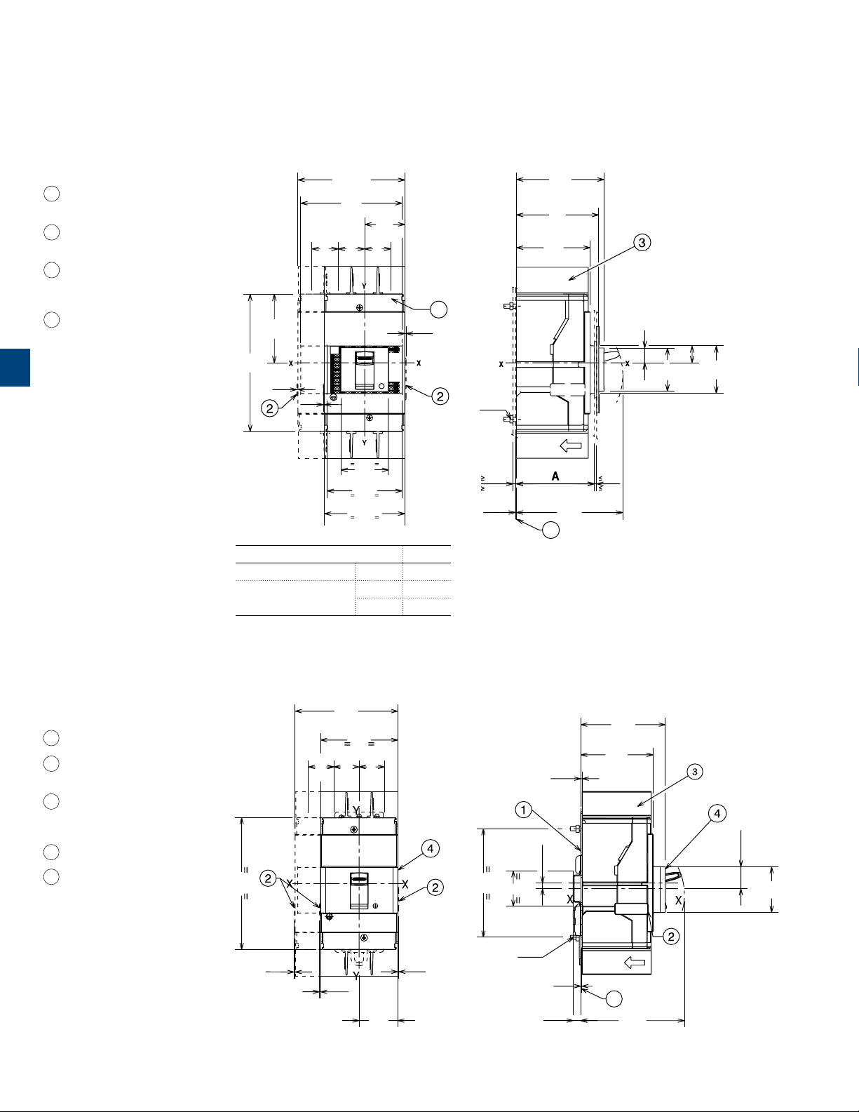
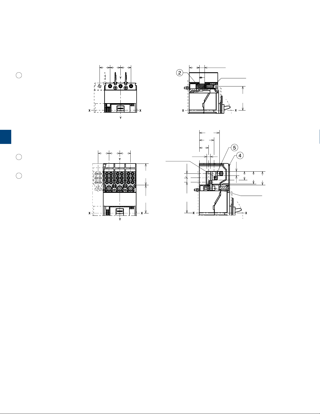
Approximate dimensions
Tmax XT1 - Installation for fixed circuit breaker
Mounting on the backplate
Captions
1 Insulating plate
(compulsory)
2 Overall dimension of
optional wiring ducts
3 25mm insulating
barriers between phases
(compulsory) provided
4 Front carter obligatory
for through door of the
panel ≤ 25mm/0,98"
5
101.2 (4P)
3.98
96
3.78
38.1
1.5
25
25
0.98
0.98250.98
65
2.56
130
5.12
1
0.04
1
0.04
45
1.77
71
2.8
76.2 (3P)
3.0
A
With standard flange III - IV 74
Without flange
III - IV 71
III - IV 79
0.04
83
3.27
78
3.07
70
2.76
4
1
0.55
16
0.63
1.61
45
1.77
1SDC21000HF0001
41
1.1Nm
3
0.12
1
0.04
101
3.97
2
0.08
14
1
Mounting on DIN 50022 rail
Captions
1 Mounting bracket
2 Overall dimension of optional
wiring ducts
3 25mm insulating barriers
between phases (compulsory)
provided
4 Optional front cover for DIN rail
5 Insulating plate
(compulsory)
5/2 SACE Tmax XT UL/CSA | US Technical Catalog
130
5.12
0,04
1
101.2
3.98
76.2
3.0
25
0.98250.98250.98
1
0,04
38.1
1.5
0,04
83,5
3.29
71,5
2.81
1,5
0.06
21.5
5.5
0.22
107
4.21
35
1.38
1.1Nm
1
7,5
0.29
0,04
1
5
102,5
4.04
0.85
45
1SDC21001HF0001
Page 2
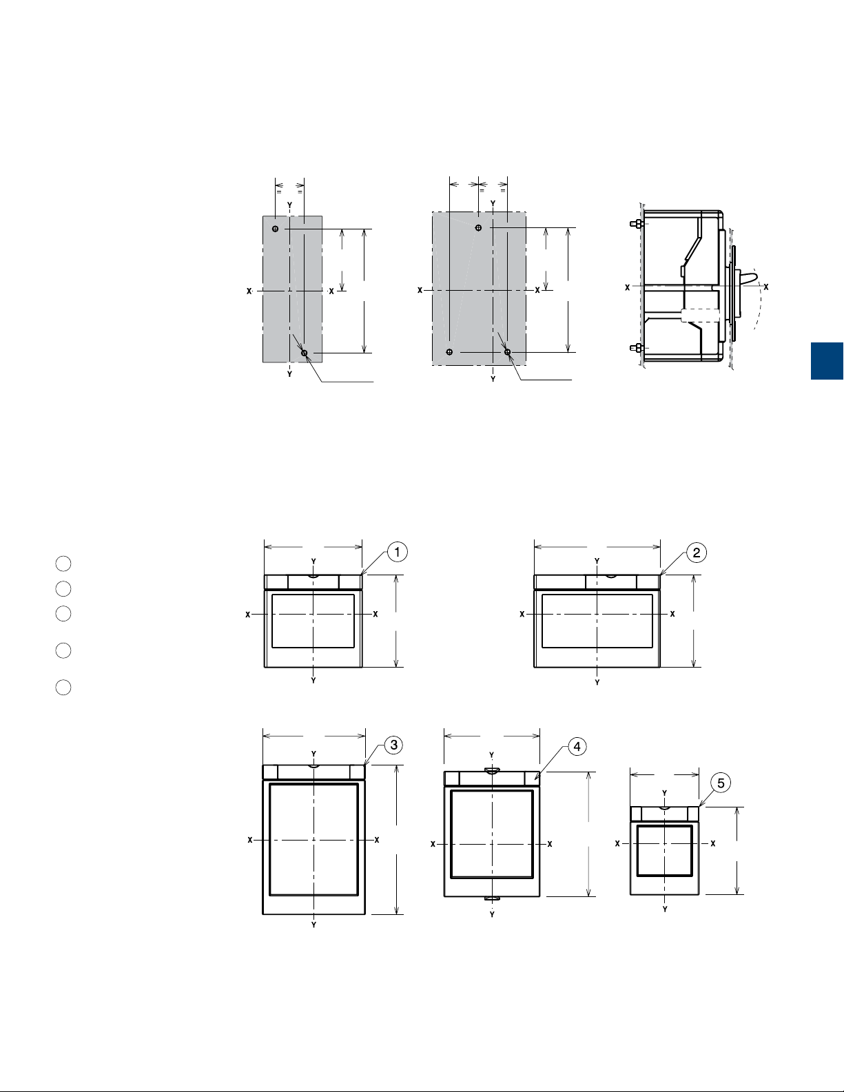
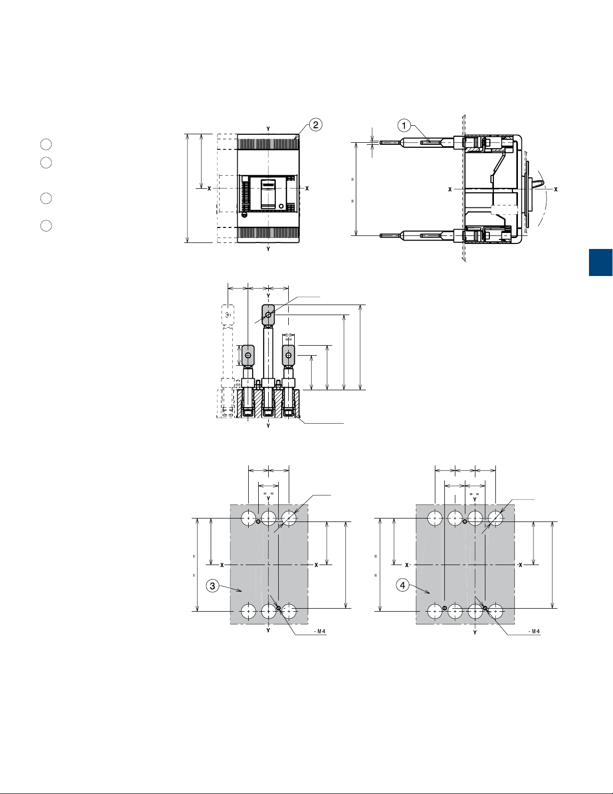
Drilling template for circuit breaker mounting
Captions
1 Flange for circuit breaker III
25
0.98
53.5
2.11
Ø 4.5 - M4
Ø 0.18 - M4
107
4.21
25
0.98250.98
3 POLES 4 POLES
Flanges
87
3.42
53.5
2.11
Ø 4.5 - M4
Ø 0.18 - M4
107
4.21
112
4.41
5
1SDC21002HF0001
2 Flange for circuit breaker IV
3 Flange for fixed III-IV with direct
motor operator (MOD)
4 Flange for III-IV with direct
rotary handle (RHD)
5 Optional flange
91
3.58
82
132.6
3.23
5.22
85
3.35
111
4.37
61
2.40
82
3.23
78
3.07
1SDC21003HF0001
US Technical Catalog | SACE Tmax XT UL/CSA 5/3
Page 3
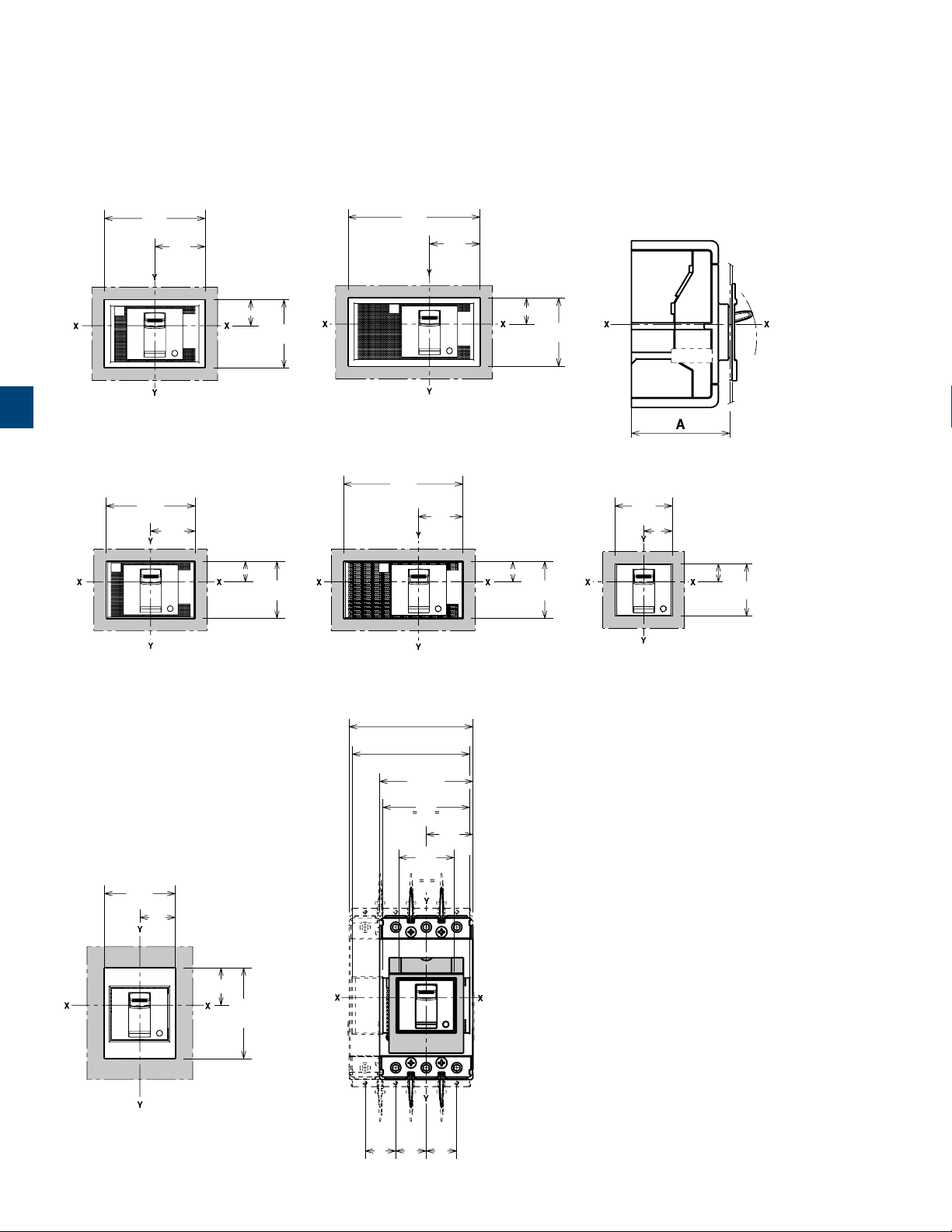
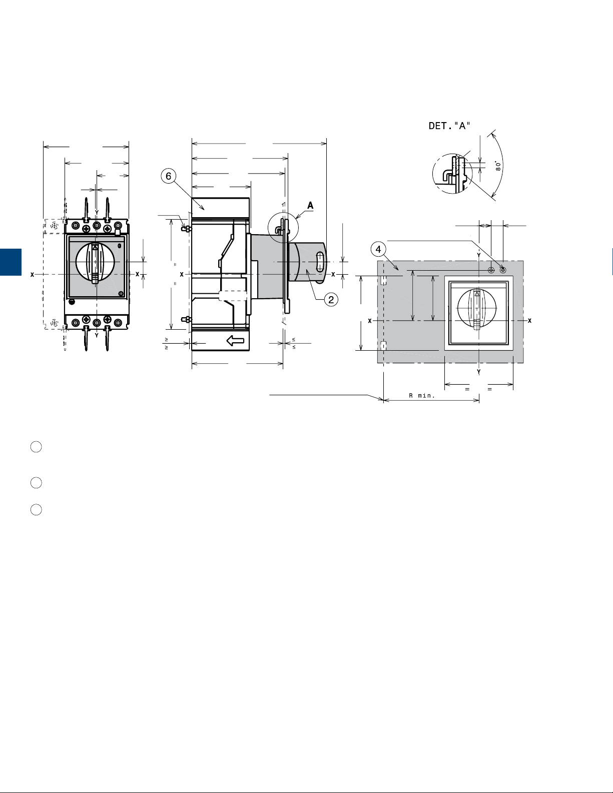
Approximate dimensions
Tmax XT1 - Installation for fixed circuit breaker
Drilling templates for compartment door
With standard flange
81
3.19
40.5
1.59
106
4.17
40.5
1.59
5
Without flange
With optional flange
A=74
3 POLES
73
2.87
36.5
1.44
A=71
3 POLES
57
2.24
28.5
1.12
21
0.83
55
2.17
21
0.83
55
2.17
A=74
0.59
43
1.69
1SDC21004HF0001
1SDC21005HF0001
4 POLES
98
3.86
36.5
1.44
17
0.67
47
1.85
17
0.67
47
1.85
A=71
4 POLES
101.2 (4P)
3.98
96
3.78
76.2 (3P)
3.0
71
2.8
38.1
1.5
45
1.77
47
1.85
23.5
0.93
A=79
3-4 POLES
15
30
1.18
73
2.87
1SDC21006HF0001
A=79
3-4 POLES
5/4 SACE Tmax XT UL/CSA | US Technical Catalog
25
0.98250.98250.98
1SDC21007HF0001
Page 4
120
145
~ 200
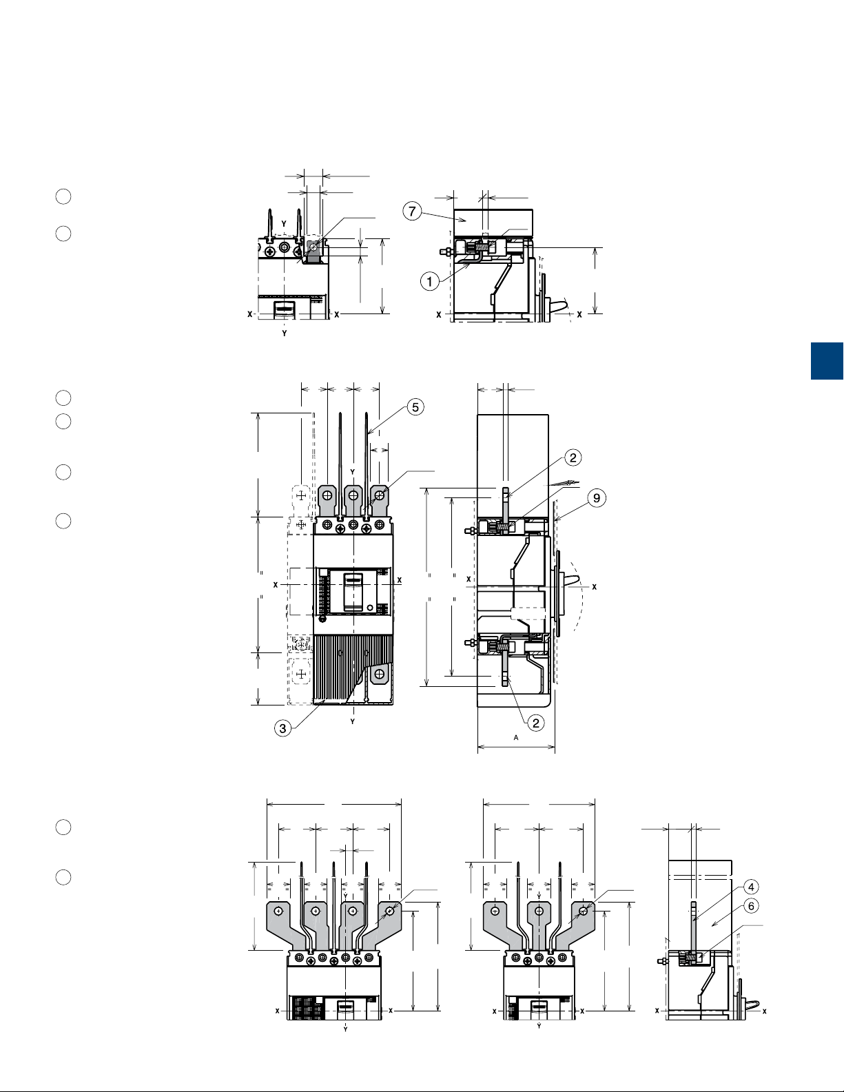
Approximate dimensions
Tmax XT1 - Terminals for fixed circuit breaker
Terminals F
Captions
1 Front terminals for busbar
connection
7 25mm insulating barriers
between phases
(compulsory) provided
Captions
2 Front extended terminals
3 High terminal covers with
degree of protection IP40
(optional) not provided
5 100mm insulating
barriers between phases
(compulsory) provided
9 Internal insulating plate
compulsory with phase
barriers (customer)
Terminals EF
25
0.98250.98250.98
~100
~ 3.94
MAX 16
11
0.43
0.63
Ø 6.5
Ø 0.26
0.29
MAX 7.5
17
0.67
24.5
0.96
65
2.56
MAX 5
0.20
6Nm
57.5
2.26
1SDC21008HF0001
5
24.5
0.9650.20
Ø 8.5
Ø 0.34
Captions
4 Front extended spread
terminals for busbar
connection
6 200mm insulating
barriers between phases
(compulsory) provided
130
5.12
50
1.97
Terminals ES
40
1.57401.57401.57
25
25
0.98
0.98
~ 7.87
5.71
0.98
190
171
7.48
6.73
1SDC21009HF0001
4.72
107.5
Ø 8.5
Ø 0.34
4.23
117.5
4.63
24.5
0.96
0.20
5
6Nm
0.98
47.5
1.87
25
0.98
25
47.5
~ 200
~ 7.87
0.98
1.87
25
7.5
0.29
25
25
0.98
Ø 8.5
Ø 0.34
107.5
4.23
117.5
4.63
1SDC21010HF0001
US Technical Catalog | SACE Tmax XT UL/CSA 5/5
Page 5
Approximate dimensions
Tmax XT1 - Installation for fixed circuit breaker
Terminals FCCu
Captions
2 Front terminal FCCu
5
Captions
4 Terminal covers with degree
of protection IP40 (compulsory) provided
5 Front terminal for multi-cable
connection
25
0.98250.98250.98
Terminals MC
25
25
0.98
0.98250.98
24.5
0.96
Ø 8.2
10
10
71,5
Ø 0.32
0.39
0.39
2.81
7Nm/61.15 in. lbs
50
1.97
65
2.56
21.5
0.85
34
1.34
12 x 12
0.47 x 0.47
46.5
1.83
7Nm/61.15 in. lbs
10
0.39
6Nm/53 in. lbs
57.5
20
2.26
1SDC21013HF0001
0.79
29
1.14
31.5
1.24
1SDC21014HF0001
5/6 SACE Tmax XT UL/CSA | US Technical Catalog
Page 6
Terminals R
Captions
1 Adjustable rear terminals
2 Bottom terminal covers with
degree of protection IP30
(optional) not provided
3 Drilling template for mounting
circuit breaker III on sheet
4 Drilling template for mounting
circuit breaker IV fixing on sheet
134
5.27
4
0.15
67
2.63
115
4.52
5
25
25
25
0.98
0.98
25/0.98
0.98
15/0.59
Ø 6.5
Ø 0.25
42.5
1.67
105
4.13
92.5
3.64
55
2.16
115
4.52
57.5
2.26
6Nm/53 in. lbs
25
25
0.98
25
0.98
0.98
Ø 4.5
Ø 18
Ø 0.70
53.5
2.10
107
4.21
115
4.52
57.5
2.26
25
0.98
25
0.98250.98
25
0.98
25
0.98
3 POLES 4 POLES
Ø 0.70
Ø 4.5
Ø 18
53.5
2.10
107
4.21
1SDC21085CF0001
US Technical Catalog | SACE Tmax XT UL/CSA 5/7
Page 7
Approximate dimensions
Tmax XT1 - Accessories for fixed circuit breaker
Rotary handle operating mechanism on circuit breakers (RHD)
5
Captions
101.2 (4P)
3.98
76.2 (3P)
3.0
38.1
2
0.08
1.5
14.5
0.57
1.1Nm
130
3
0.12
5.12
70
2.76
113.75
4.48
110
4.33
108
4.25
159.25
6.27
2
0.08
MINIMUM ROTATION RADIUS FOR
DOOR FULCRUM
(14.5)
(0.57)
DRILLING: SEE DET. “A”
88
3.46
59.5
2.34
52.8
2.08
200
7.87
14.5
0.57
81
3.19
Ø 3.5
Ø 0.14
14
0.55
1SDC21015HF0001
2 Rotary handle operating
mechanism on circuit
breaker RHD
4 Door drilling template with
direct rotary handle
6 25mm insulating barriers
between phases
(compulsory) provided
5/8 SACE Tmax XT UL/CSA | US Technical Catalog
Page 8

Rotary handle operating mechanism on the compartment door (RHE)
22.5
0.89
Ø 5
Ø 0.20
101.2 (4P)
3.98
76.2 (3P)
3.0
2
0.08
23.5
0.93
38.1
1.5
0.08
3
0.12
1.1Nm
14.5
0.57
46.8
1.84
130
5.12
3
0.12
2
1.1Nm
14.5
0.57
45
1.77
HEIGHTS FOR DOOR WITH MAXIMUM DISTANCE
161.70
70
2.76
6.37
47.95
1.89
(14.5)
(0.57)
HEIGHTS FOR DOOR WITH MINIMUM DISTANCE
161.70
6.37
70
2.76
(14.5)
(0.57)
47.95
1.89
1.1Nm
175.43
1.4Nm
6.90
585.45
23.05
463
18.23
46
1.81
2
0.08
1.4Nm
Ø 54
2
0.08
Ø 2.13
46
1.81
Ø 54
Ø 2.13
5
200
7.87
MINIMUM ROTATION RADIUS
Captions
1 Transmitted rotary handle
3 Door drilling template with
transmitted rotary handle
5 Transmission unit
6 25mm insulating barriers
between phases provided
with circuit breaker
Ø 5
Ø 0.20
23.5
0.93
FOR DOOR FULCRUM
1.1Nm
53
2.08
1SDC21016HF0001
US Technical Catalog | SACE Tmax XT UL/CSA 5/9
Page 9

Approximate dimensions
Tmax XT1 - Accessories for fixed circuit breaker
Large rotary handle operating mechanism on the compartment door (RHE-LH)
101.2 (4P)
3.98
76.2 (3P)
3.0
2
38.1
0.08
1.5
14.5
0.57
46.8
1.84
130
5.12
5
70
2.76
161.70
6.37
47.95
1.89
463
18.23
1
0.04
1
0.04
1
0.04
1.1Nm
3
0.12
HEIGHTS FOR DOOR WITH MAXIMUM DISTANCE
2
0.08
22.5
Ø 55
Ø 2.17
0.89
200
7.87
Ø 5
Ø 0.20
23.5
0.93
Ø 5
Ø 0.20
585.45
23.05
14.5
0.57
45
1.77
46
1.81331.30
2
0.08
1SDC21017HF0001
Captions
1 Transmission unit
2 25mm insulating barriers
between phases provided
with circuit breaker
3 Optional wiring ducts
4 Wide type rotary handle
5 Door drilling template with
extended rotary handle
5/10 SACE Tmax XT UL/CSA | US Technical Catalog
Page 10

1
0.04
101.2 (4P)
3.98
76.2 (3P)
3.0
2
0.08
38.1
1.5
14.5
0.57
46.8
1.84
130
5.12
70
2.76
161.70
6.37
47.95
1.89
53
2.08
5
1
0.04
Captions
1 Transmission unit
2 25mm insulating barriers
between phases
(compulsory) provided
3 Optional wiring ducts
4 Wide type rotary handle
1
0.04
1.1Nm
3
0.12
HEIGHTS FOR DOOR WITH MINIMUM DISTANCE
175.45
6.90
46
1.81
2
0.08
1SDC21018HF0001
US Technical Catalog | SACE Tmax XT UL/CSA 5/11
Page 11

Approximate dimensions
Tmax XT1 - Accessories for fixed circuit breaker
Direct motor operator (MOD)
Captions
3 Key lock (not provided)
4 Direct motor operator (MOD)
5 Drilling template of door with
MOD without flange
6 Drilling template of door with
MOD with flange
7 Cable connections
8 25mm phase barriers
5
130
5.12
28.5
1.12
1.1Nm
101.2 (4P)
3.98
76.2 (3P)
77
3.03
38.5
1.52
3.0
12.6
0.50
38.1
1.55
1.1Nm
3
0.12
70
2.76
87
3.42
43.5
1.71
172
6.77
207
8.15
2
0.08
1SDC21019HF0001
49
1.93
98
3.86
54
2.13
108
4.25
1SDC21020HF0001
5/12 SACE Tmax XT UL/CSA | US Technical Catalog
Page 12

4.88
RC Inst and RC Sel residual current release for 3-pole circuit breaker
Captions
1 Front terminals for busbar
connection
2 Terminal covers with degree of
protection IP40
3 Drilling template of door with
direct rotary handle with flange
4 Drilling template of door with
direct rotary handle without
flange
5 Drilling template for mounting
circuit breaker on sheet
187
67
7.36
2.63
83
3.26
106.2
4.18
25
0.98250.98
76.2
3.00
71
2.79
45
1.77
38.1
1.50
35.5
1.39
70
2.75
24.5
0.96
12x12
0.47x0.47
11.5
0.45
16
115
4.52
0.62
45
1.77
5
2
3
0.11
70
2.75
101
3.97
2.08
0.07
53
25
0.98
With standard flange III 74
Without flange III 71
53.5
2.10
107
105.6
4.15
113.5
4.46
36.5
1.43
40.5
1.59
17
0.66
47
1.85
Ø 4.5
Ø 0.17
21
0.82
55
2.16
4.21
124
1SDC21095CF0001
A
US Technical Catalog | SACE Tmax XT UL/CSA 5/13
Page 13

Approximate dimensions
Tmax XT1 - Accessories for fixed circuit breaker
RC Inst and RC Sel residual current release for 4-pole circuit breaker
Captions
1 Front terminals for busbar
connection
2 Terminal covers with degree of
protection IP40
3 Drilling template of door with
direct rotary handle with flange
4 Drilling template of door with
direct rotary handle without
flange
5
5 Drilling template for mounting
circuit breaker on sheet
187
83
7.36
3.26
131.2
5.16
101.2
3.98
38.1
1.50
96
67
2.63
3.73
45
1.77
25
0.98250.98250.98
35.5
1.39
70
2.75
115
4.52
11.5
0.45
3
0.11
24.5
0.96
70
2.75
0.47x0.47
3.97
78
3.07
12x12
101
25
0.98250.98
0.07
16
0.62
45
1.77
2
A
With standard flange IV 74
Without flange IV 71
5/14 SACE Tmax XT UL/CSA | US Technical Catalog
105.6
4.15
113.5
4.46
36.5
1.43
40.5
1.59
53.5
2.10
107
4.21
124
17
0.66
47
1.85
Ø 4.5
Ø 0.17
21
0.82
55
2.16
4.88
1SDC21096CF0001
Page 14

4.21
RC Sel 200 4-pole residual current release
Captions
1 Front terminals for busbar
connection
2 Terminal covers with degree of
protection IP40
3 Drilling template of door with
direct rotary handle
4 Drilling template for mounting
circuit breaker on sheet
155.5
6.12
24.5
0.96
70
2.75
2.79
71
101
3.97
87.5
3.44
0.07
25
0.98250.98
16
0.62
45
1.77
5
2
53.5
2.10
153.2
6.03
101.2
3.98
38.1
1.50
96
65
2.56
3.77
45
1.77
25
0.98250.98250.98
168.2
6.62
35.5
1.39
115
11.5
4.52
0.11
0.45
3
70
2.75
83
3.26
152.5
6.00
36.5
1.43
78
3.07
Ø 4.5
Ø 0.17
17
0.66
47
1.85
1SDC21097CF0001
107
US Technical Catalog | SACE Tmax XT UL/CSA 5/15
Page 15

Approximate dimensions
Tmax XT1 - Installation for plug-in circuit breaker
Mounting on the backplate
Captions
1 Fixed part
2 Moving part
Fixing at 50mm A
With standard flange III - IV 124
Without flange
III - IV 121
III - IV 129
5
Fixing at 70mm for
A
extended front terminals
With standard flange III - IV 144
Without flange
III - IV 141
III - IV 149
Drilling template for mounting circuit breaker
75
2.95
37.5
1.48
101.2 (4P)
3.98
25
0.98250.98250.98
76.2 (3P)
3.0
38.1
1.5
100
3.94
37.5
1.48
146
5.75
1.1Nm
3
0.12
152
5.98
120
4.72
133
5.24
128
5.04
2
0.08
14
16
0.55
0.63
134
5.27
45
41
1.77
1.61
1SDC21021HF0001
74
2.91
35
1.38
Ø 4.5 - M4
Ø 0.18
29.5
1.16
59
2.32
3 POLES
Ø 4.5 - M4
Ø 0.18
59
2.32
29.5
1.16
3 POLES
74
2.91
35
1.97
1.38
84
3.31
29.5
1.16
25
0.98
50
25
0.98
50
Ø 4.5 - M4
Ø 0.18
1.97
1SDC21022HF0001
4 POLES
25
0.98
50
1.97
29.5
1.16
84
3.31
25
0.98
Ø 4.5 - M4
Ø 0.18
50
1.97
1SDC21023HF0001
4 POLES
5/16 SACE Tmax XT UL/CSA | US Technical Catalog
Page 16

Flanges
Captions
1 Flange for plug-in circuit
breaker III
2 Flange for circuit breaker IV
5 Flange for plug-in circuit
breaker III-IV with direct motor
operator (MOD)
6 Flange for plug-in circuit
breaker III-IV with direct rotary
handle RHD
7 Optional flange
87
3.42
91
3.58
82
3.23
132.6
5.22
112
4.41
85
3.35
82
111
3.23
5
4.37
61
2.40
78
3.07
1SDC21024HF0001
US Technical Catalog | SACE Tmax XT UL/CSA 5/17
Page 17

Approximate dimensions
Tmax XT1 - Installation for plug-in circuit breaker
Drilling templates for compartment door
With standard flange
5
Without flange
81
3.19
1.57
3 POLES
73
2.87
36.5
1.44
106
4.17
40
21
0.83
55
2.17
40.5
1.59
21
0.83
55
2.17
4 POLES
1SDC21025HF0001
98
3.86
36.5
1.44
17
0.67
47
1.85
17
0.67
47
1.85
47
1.85
23.5
0.93
15
0.59
43
1.69
1SDC21026HF0001
3 POLES
With optional flange
57
2.24
28.5
1.12
30
1.18
73
2.87
1SDC21027HF0001
3-4 POLES
5/18 SACE Tmax XT UL/CSA | US Technical Catalog
4 POLES
101.2 (4P)
3.98
96
3.78
76.2 (3P)
3.0
71
2.8
45
1.77
25
0.98250.98250.98
38.1
1.5
3-4 POLES
1SDC21028HF0001
Page 18

Approximate dimensions
Tmax XT1 - Terminals for plug-in circuit breaker
Terminals EF
25
25
0.98
0.98250.98
0.43
~ 100
~ 3.94
Captions
4 Front extended terminals
5 100mm insulating barriers
between phases (compulsory)
provided
Terminals ES
145
5.71
25
0.98
40
1.57
25
0.98
40
1.57
11
Ø 0.24
Ø 6
15.5
0.98
153
6.02
148
5.83
70
2.76
0.16
140
5.51
4
0.61
50
1.97
20.5
4
0.81
0.16
6Nm
83
88.5
3.48
3.27
40.5
1.59
5
1SDC21029HF0001
MOUNTING AT 50mm
40
1.57
7.5
0.29
25
25
0.98
25
0.98
47.5
1.87
120
4.72
25
0.98
47.5
1.87
25
0.98
MOUNTING AT 70mm
70
2.76
24.5
MAX 5
0.20
0.96
Ø 8.5
Ø 0.34
~ 200
~ 7.87
90.5
3.56
Captions
3 Front extended spread
terminals
6 200mm insulating barriers
between phases (compulsory)
provided
7 Adapter (compulsory) not
provided
133
5.24
143
5.63
~ 200
90.5
Ø 8.5
Ø 0.34
~ 7.87
3.56
133
6Nm
143
5.63
5.24
83
57.5
2.26
1.1Nm
MOUNTING AT 50mm
US Technical Catalog | SACE Tmax XT UL/CSA 5/19
3.27
30HF0001
1SDC210
Page 19

4.58
Approximate dimensions
Tmax XT1 - Terminals for plug-in circuit breaker
1x1.5...50mm2 terminals FCCuAl
Captions
1 1x1.5...50mm2 front terminal
FCCuAl
5 Adapter (compulsory) optional
6 25mm insulating barriers
between phases (compulsory)
provided
5
Captions
1 External terminal FCCuAl
2 High terminal covers with
degree of protection IP40
(optional) provided
25
0.98250.98250.98
25
0.98
90.5
3.56
1x35...95mm2 terminals FCCuAl
25
0.98250.98250.98
67.5
27.5
1.08
15
0.59
83
3.26
MOUNTING AT 50mm
35
1.37
2.65
9.5 x 9.5
0.37 x 0.37
15
0.59
1SDC21089CF0001
Captions
4 Terminals FCCu
5 Adapter (compulsory) not
provided
6 25mm insulating barriers
between phases (compulsory)
provided
Terminals FCCu
25
0.98250.98250.98
90.5
3.56
4.89
124.25
5.53
140.5
12
0.47
83
3.26
MOUNTING AT 50mm
24.5
0.96
12 x 12
0.47 x 0.47
1SDC21062FF0001
116.5
83
3.26
1SDC21018FF0001
5/20 SACE Tmax XT UL/CSA | US Technical Catalog
Page 20

1.22
61.75
2.43
61.75
2.43
57.5
2.26
57.5
2.26
15
0.59
15.2
0.60
8.2
0.32
8.2
0.32
Captions
2 Terminal covers with degree
of protection IP40 (optional)
provided
3 Front terminal for multi-cable
connection
5 Adapter (compulsory) not
provided
Terminals MC
Terminals HR/VR
46.5
1.83
34
1.33
21.5
0.84
8.2
0.32
10
10
0.39
73
2.87
10
0.39
5.53
140.5
97
3.81
0.39
20
0.78
29
31
1.14
5
1SDC21091CF0001
MOUNTING AT 50mm
Captions
1
Rear vertical terminals
2
Rear horizontal terminals
3 90mm insulating barriers
between phases (compulsory)
not provided
57.5
2.26
15.2
0.60
57.5
2.26
15
0.59
8.2
0.32
61.75
61.75
2.43
2.43
8.2
0.32
MOUNTING AT 50mm MOUNTING AT 50mm
80.5
3.16
73
2.87
40.5
1.59
33
1.29
25
0.98
25
0.98
25
0.98
90
3.54
25
0.98
25
0.98
15
0.59
25
0.98
8.2
0.32
90
3.54
15.2
0.60
80.5
3.16
73
2.87
40.5
1.59
33
1.29
1SDC21092CF0001
US Technical Catalog | SACE Tmax XT UL/CSA 5/21
Page 21

Approximate dimensions
Tmax XT1 - Terminals for plug-in circuit breaker
Terminals HR/VR
5
Captions
1
Rear vertical terminals
2
Rear horizontal terminals
3 90mm insulating barriers
between phases (compulsory)
not provided
57.5
57.5
6Nm
2.43
2.26
2.26
Ø 8.2
Ø 0.32
15.2
0.60
15
0.59
61.75
61.75
2.43
4
0.16
MOUNTING AT 50mm MOUNTING AT 50mm
80.5
3.16
73
2.87
40.5
1.59
33
1.30
25
25
25
Ø 8.2
Ø 0.32
0.98
0.98
0.98
15
0.59
25
0.98
25
0.98
25
0.98
4
0.16
~ 90
~ 3.54
Ø 8.2
Ø 0.32
~ 90
~ 3.54
15.2
0.60
80.5
3.16
73
2.87
40.5
1.59
1.30
6Nm
33
1SDC21031HF0001
5/22 SACE Tmax XT UL/CSA | US Technical Catalog
Page 22

Approximate dimensions
Tmax XT1 - Accessories for plug-in circuit breaker
Direct motor operator (MOD)
Captions
1 Fixed part
2 Moving part
3 Key lock (not provided)
4 Direct motor operator (MOD)
5 Drilling template of door with
MOD without flange
6 Drilling template of door with
MOD with flange
7 Cable connection
146
5.75
28.5
1.12
12.6
0.50
77
3.03
101.2 (4P)
3.98
76.2 (3P)
38.5
1.52
257
120
3.0
38.1
1.5
50
1.97
4.72
10.12
5
3
0.12
222
8.74
MOUNTING AT 50mm
87
3.42
43.5
1.71
2
0.08
1SDC21032HF0001
49
1.93
98
3.86
54
2.13
108
4.25
1SDC21033HF0001
US Technical Catalog | SACE Tmax XT UL/CSA 5/23
 Loading...