

Page 1

Wiring diagrams
Information on how to read the diagrams
Shown
The diagrams are shown in the following conditions:
– fixed version circuit breaker, open;
– withdrawable or plug-in version circuit breaker, open and connected;
– contactor for starting the motor open;
– circuits de-energized;
– trip units not tripped;
– motor operator with springs charged.
The diagram shows a circuit breaker or a switch-disconnector in the withdrawable or plug-in version, but is also valid for fixed
version circuit breakers or switch-disconnectors.
For fixed version circuit breakers, auxiliary circuits are headed at terminal box XV: connectors J.. and XB.., XC.., XD.. and XE..
are not supplied.
For plug-in version circuit breakers, auxiliary circuits are headed at connectors XB.., XC.., XD.. and XE..: connectors J.. are not
supplied.
For withdrawable version circuit breakers, auxiliary circuits are headed at connectors J..: connectors XB.., XC.., XD.. and XE..
6
are not supplied.
6/2 SACE Tmax XT UL/CSA | US Technical Catalog
Page 2
Wiring diagrams
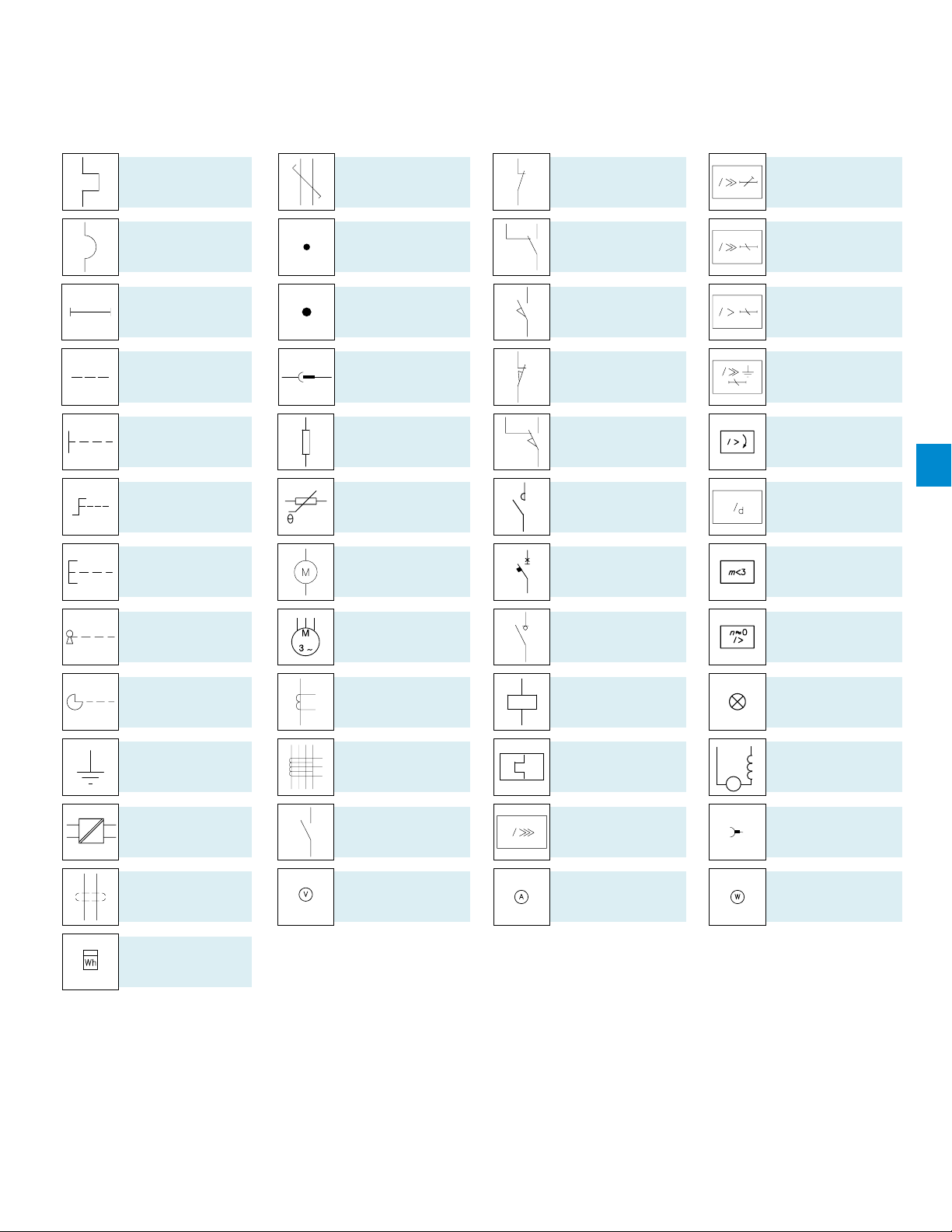
Graphic symbols (IEC 60617 and CEI 3-14 …3-26 Standards)
Thermal effect
Electromagnetic effect
Timing
Mechanical connection
Manual mechanical
operating mechanism
(general case)
Rotary handle operating
mechanism
Pushbutton operating
mechanism
Conductors with corded
cables (example two
conductors)
Connection of conductors
Terminal or clamp
Socket and plug
(female and male)
Resistor
(general symbol)
Resistor dependent on
the temperature
Motor
(general symbol)
Opening contact
Changeover contact with
momentary break
Closing position contact
(limit switch)
Opening position contact
(limit switch)
Changeover contact
with momentary break
(limit switch)
Contactor
(closing contact)
Power cut-off of switchdisconnector power with
automatic opening
Short adjustable time
delay characteristic
Overcurrent release with
short inverse adjustable
time delay characteristic
Overcurrent release with
long inverse adjustable
time delay characteristic
Overcurrent release for
earth fault with short
inverse time characteristic
Current relay for
unbalance between
phases
Residual current release
Relay for detecting lack
of phase in a three-phase
system
6
Key operating
mechanism
Cam operating
mechanism
Ground
(general symbol)
Converter separated
galvanically
Conductors in shielded
cable (example two
conductors)
Watt-hour meter
Three-phase asynchronous motor, with shortcircuited rotor (cage)
Current transformer
Current transformer with primary consisting of 4 passing
conductors and with wound
secondary, with socket
Closing contact
Voltmeter
Switch-disconnector
Control coil
(general symbol)
Thermal trip unit
Instantaneous overcurrent
release
Ammeter
Overcurrent release with
Relay for detecting
blocked rotor by means
of current measurement
Lamp, general symbol
Motor with excitation
in series
M
Brush
Wattmeter
US Technical Catalog | SACE Tmax XT UL/CSA 6/3
Page 3
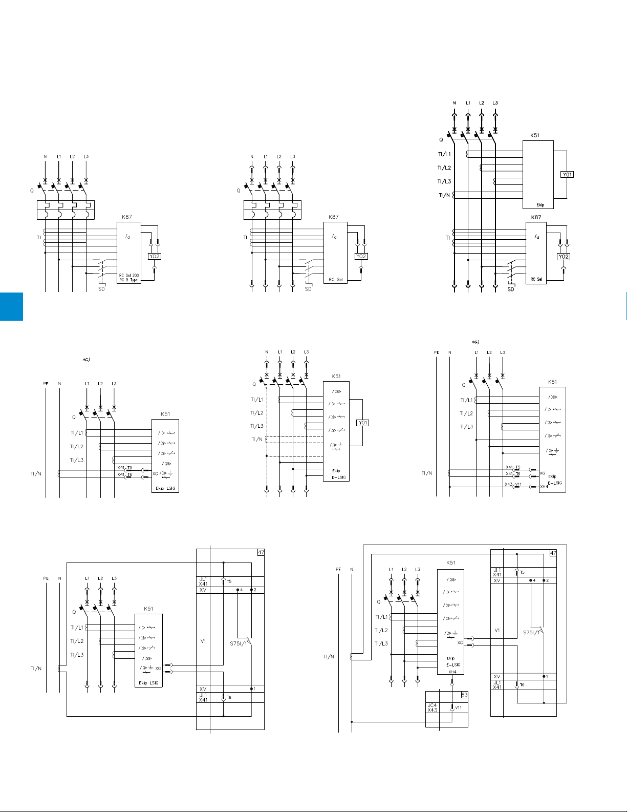
Wiring diagrams of the circuit breakers
Four-pole circuit breaker with thermal
6
magnetic trip unit and RC Sel 200 or RC
B type residual current release
Three-pole fixed version circuit breaker
with current transformer on the neutral
conductor outside the circuit breaker
1SDC21084DF0001
1SDC21087DF0001
Four-pole circuit breaker with thermal
magnetic trip unit and
RC Sel residual current release
Three-pole or four-pole XT4
circuit breaker with Ekip E-LSIG
microprocessor based release
1SDC21085DF0001
1SDC21079GF0001
1SDC21086DF0001
Four-pole circuit breaker with
electronic trip unit and RC Sel
residual current release
1SDC21080GF0001
Fixed version three-pole XT4 circuit breaker
with Ekip E-LSIG with current transformer on
neutral conductor, external to circuit breaker
Diagram recommended for three-pole plug-in or
withdrawable version circuit breakers with current transformer
on the neutral conductor outside the circuit breaker
6/4 SACE Tmax XT UL/CSA | US Technical Catalog
1SDC21088DF0001
1SDC21081GF0001
Recommended diagram for plug-in or withdrawable version three-pole
circuit breakers with current transformer and voltage connection
on neutral conductor, external to circuit breaker
Page 4

Description of figures
Fig. 47 = Current transformer circuit on the neutral conductor outside the circuit breaker (for plug-in or withdrawable version circuit
breaker).
Fig. 63 = Circuit of the voltage socket on the neutral conductor outside the circuit breaker (for Ekip E_LSIG type microprocessor-
based plug-in or withdrawable circuit breaker).
Notes
G) To remove the circuit breaker from a three-pole fixed version with a current transformer on the neutral conductor outside
the circuit breaker, the TI/N transformer terminals must be short-circuited.
Caption
= Diagram figure number
* = See the note indicated by the letter
J.. = Connectors for the auxiliary contacts of the withdrawable version circuit breaker; connectors and circuit breaker are
extracted simultaneously.
K51 = Electronic trip unit:
– overcurrent release type Ekip I, Ekip LS/I, Ekip N-LS/I, Ekip LSI, Ekip LSIG, Ekip E-LSIG
– of motor protection type Ekip M-LIU
K87 = Residual current release type RC Inst, RC Sel, RC Sel 200, RC B Type
Q = Main circuit breaker
S75I/1..4 = Contacts for electrical signaling of circuit breaker in the connected position (only provided with plug-in or withdrawable
version circuit breakers)
S75S/1-2 = Contacts for electrical signaling of circuit breaker in the racked-out position (only provided with withdrawable version
circuit breakers)
SD = Power supply switch-disconnector of the residual current release type RC Inst, RC Sel, RC Sel 200 or RC B Type
TI = Toroidal current transformer
TI/L1 = Current transformer placed on phase L1
TI/L2 = Current transformer placed on phase L2
TI/L3 = Current transformer placed on phase L3
TI/N = Current transformer placed on the neutral
V1 = Circuit breaker applications
X41 = Circuit connector for external neutral
XG-XH = Electronic trip unit connectors
XV = Terminal boxes of circuit breaker applications
YO1 = Opening solenoid of the microprocessor-based overcurrent release
YO2 = Opening solenoid of the residual current release
6
US Technical Catalog | SACE Tmax XT UL/CSA 6/5
Page 5

Wiring diagrams of the circuit breakers
1SDC21090DF0001
Three-pole or four-pole circuit breaker with
TMF or TMA thermal magnetic trip unit
Three-pole circuit breaker
with MCP (MA) magnetic trip unit
1SDC21089DF0001
1SDC21091DF0001
Three-pole or four-pole molded
case switch-disconnector
6
Three-pole or four-pole circuit breaker
with Ekip LS/I electronic trip unit
1SDC21092DF0001
Three-pole or four-pole circuit breaker
with Ekip I, Ekip LSI or Ekip LSIG
electronic trip unit
1SDC21093DF0001
1SDC21095DF0001
Three-pole circuit breaker with
Ekip M-LIU electronic trip unit
6/6 SACE Tmax XT UL/CSA | US Technical Catalog
1SDC21096DF0001
Three-pole or four-pole circuit breaker
with thermal magnetic trip unit and RC
Inst or RC Sel residual current release
Page 6

Captions
= Diagram figure number
* = See the note indicated by the letter
K51 = Microprocessor-based release:
– overcurrent release type Ekip I, Ekip LS/I, Ekip N-LS/I, Ekip LSI, Ekip LSIG, Ekip E-LSIG
– motor protection release type Ekip M-LIU
K87 = Residual current release type RC Inst, RC Sel, RC Sel 200, RC B Type
Q = Main circuit breaker
SD = Power supply switch-disconnector of the residual current release type RC Inst, RC Sel, RC Sel 200 or RC B Type
TI = Toroidal current transformer
TI/L1 = Current transformer placed on phase L1
TI/L2 = Current transformer placed on phase L2
TI/L3 = Current transformer placed on phase L3
TI/N = Current transformer placed on the neutral
YO1 = Opening solenoid of the microprocessor-based overcurrent release
YO2 = Opening solenoid of the residual current release
6
US Technical Catalog | SACE Tmax XT UL/CSA 6/7
Page 7

Wiring diagrams of the accessories
Service releases
6
1SDC21097DF0001
Description of figures
Fig. 1 = Shunt opening release.
Fig. 2 = Supplementary shunt opening release (only for four-pole circuit breakers).
Fig. 5 = Instantaneous undervoltage release (see Notes B and F).
Fig. 6 = Undervoltage release with electronic time delay device outside the circuit breaker, see note B).
Notes
B) The undervoltage release is supplied for power supply branched on the supply side of the circuit breaker or from an
F) Additional external resistor for undervoltage supplied at 380/440V AC and 480/525V AC.
independent source: closing is only possible with the release energized (the lock on closing is made mechanically).
Caption
= Diagram figure number
* = See the note indicated by the letter
D = Undervoltage release electronic time delay device (outside the circuit breaker) (only for voltages up to 250V)
J.. = Connectors for the auxiliary contacts of the withdrawable version circuit breaker; connectors and circuit breaker are extracted
Q/0..7 = Circuit breaker auxiliary contacts
R = Resistor (see note F)
SO = Pushbutton or contact for opening the circuit breaker
V1 = Circuit breaker applications
V4 = Indicative apparatus and connections for control and signaling, outside the circuit breaker
XB.. = Three-way connector for the plug-in version circuit breaker auxiliary circuits
XV = Terminal boxes of circuit breaker applications
YO = Shunt opening release
YU = Undervoltage release (see note B)
simultaneously
6/8 SACE Tmax XT UL/CSA | US Technical Catalog
Page 8

Service releases
1SDC21098DF0001
Description of figures
Fig. 7 = Instantaneous undervoltage release in the version for machine tools with one contact in series (see notes B, C and F).
Fig. 8 = Instantaneous undervoltage release in the version for machine tools with two contacts in series (see Notes B, C and F).
Fig. 9 = First auxiliary early contact operated by the crank handle.
Fig. 10 = Second auxiliary early contact operated by the crank handle.
Fig. 11 = One changeover contact for electrical signaling of circuit breaker open due to tripping of the residual current release type RC
Inst, RC Sel, RC B Type or RC Sel 200.
Fig. 12 = Residual current release circuits type RC Sel, RC B Type or RC Sel 200.
Fig. 13 = Two contacts for electrical signaling of residual current release pre-alarm and alarm type RC Sel,
RC B Type or RC Sel 200.
6
Notes
B) The undervoltage release is supplied for power supply branched on the supply side of the circuit breaker or from an
C) Contacts S4/1 and S4/2 shown in figures 7-8 open the circuit with the circuit breaker open and reclose it when a manual
F) Additional external resistor for undervoltage supplied at 480/525V AC.
independent source: closing is only possible with the release energized (the lock on closing is made mechanically).
closing command is given by means of the rotary handle, in accordance with the Standards regarding machine tools (in any
case closing does not take place if the undervoltage release is not supplied).
Caption
= Diagram figure number
* = See the note indicated by the letter
J.. = Connectors for the auxiliary contacts of the withdrawable version circuit breaker; connectors and circuit breaker are extracted
K87 = Residual current release type RC Inst, RC Sel, RC Sel 200, RC B Type
R = Resistor (see note F)
S4/1-4 =
S87/1 = Contact for electrical signaling of pre-alarm of the residual current release type RC Sel, RC B or RC Sel 200
S87/2 =
S87/3 = Contact for electrical signaling of circuit breaker open due to tripping of the residual current release type RC Sel, RC Inst, RC
SO = Pushbutton or contact for opening the circuit breaker
V1 = Circuit breaker applications
V4 = Indicative apparatus and connections for control and signaling, outside the circuit breaker
XB.. = Three-way connector for the plug-in version circuit breaker auxiliary circuits
XC.. = Six-way connector for the plug-in version circuit breaker auxiliary contacts
XV = Terminal boxes of the circuit breaker applications
YU = Undervoltage release (see note B)
simultaneously
Auxiliary early contacts operated by the circuit breaker mounted crank handle (see note C)
Contact for electrical signaling of alarm of the residual current release type RC Sel, RC B or RC Sel 200
B or RC Sel 200
US Technical Catalog | SACE Tmax XT UL/CSA 6/9
Page 9

Wiring diagrams of the accessories
Motor operator
6
1SDC21099DF0001
Description of figures
Fig. 21 =
Fig. 22 = Motor operator with stored energy (MOE) (only for circuit breakers XT2 and XT4).
Fig. 23 = A contact for electrical signaling of stored energy motor operator that can be operated remotely.
Direct control motor operator (MOD) (only for XT1 and XT3 fixed or plug-in circuit breakers) (see note I).
Notes
F) Additional external resistor for MOD and MOE supplied at 480/525V AC.
Caption
= Diagram figure number
* = See the note indicated by the letter
A17 = Actuator unit type MOE for the stored energy motor operator
H2 = Signaling lamp for stored energy motor operator blocked
J.. = Connectors for the auxiliary contacts of the withdrawable version circuit breaker; extraction of the connectors takes place at
M = Motor with excitation in series for opening and closing the circuit breaker (fig. 21)
M = Motor for opening the circuit breaker and spring charging for closing the circuit breaker (fig. 22)
M1 = Three-phase asynchronous motor
R1 = Resistor (see note F)
S1 = Contact controlled by the cam of the motor operator
S2 = Contact controlled by the key lock of the motor operator with direct action
S3/1-2 = Contacts controlled by the Auto/Manual selector and key lock of the stored energy motor operator
S4 = Contact controlled by the cam of the motor operator with direct action
S6/1-2 = Contacts controlled by the Auto/Manual selector of the motor operator with direct action
SC = Pushbutton or contact for closing the circuit breaker
SO = Pushbutton or contact for opening the circuit breaker
V2 = Motor operator applications
V4 = Indicative apparatus and connections for control and signaling, outside the circuit breaker
XD.. = Nine-way connector for the auxiliary circuits of the plug-in version circuit breaker
XV = Terminal boxes of the circuit breaker applications
YC = Shunt closing release of the stored energy motor operator
the same time as that of the circuit breaker
6/10 SACE Tmax XT UL/CSA | US Technical Catalog
Page 10

Signaling contacts
1SDC21000EF0001
Description of figures
Fig. 31 = One changeover contact for electrical signaling of circuit breaker open or closed and one changeover contact for electrical
signaling of circuit breaker open due to tripping of the magnetic, thermal magnetic or electronic trip units, YO, YO1, YO2, YU
(tripped position) (only for voltages up to 250V) (see notes E and I).
Fig. 32 = Two changeover contacts for electrical signaling of circuit breaker open or closed, two changeover contacts for electrical
signaling of circuit breaker open due to tripping of the magnetic, thermal magnetic or electronic trip units, YO, YO1, YO2, YU
(tripped position) and one changeover contact for electrical signaling of circuit breaker open due to tripping of the thermal
magnetic or electronic trip unit (only for voltages up to 250V).
Fig. 33 = Three changeover contacts for electrical signaling of circuit breaker open or closed and two changeover contacts for electrical
signaling of circuit breaker open due to tripping of the magnetic, thermal magnetic or electronic trip units, YO, YO1, YO2, YU
(tripped position) (only for voltages up to 250V).
6
Notes
E) The 24V auxiliary power supply unit of fig. 48 must be installed in the circuit breaker seats marked SY/1 and Q/2. Therefore,
I) If the MOD (application in figure 21) and the auxiliary contacts 1Q+1SY (in figure 31) must be installed simultaneously, contact
should you want to install the unit in fig. 48 and the contacts in fig. 31 at the same time, the contacts of fig. 31 must be
installed in the adjacent slots; that is, contact SY/1 in the slot marked SY/2 and contact Q/2 in the slot marked Q/1.
Q/2 must be installed in the slot marked as Q/1
Captions
= Diagram figure number
* = See the note indicated by the letter
J.. = Connectors for the auxiliary contacts of the withdrawable version circuit breaker; connectors and circuit breaker are extracted
Q/0..3 = Circuit breaker auxiliary contacts
S51 = Contact for electrical signaling of circuit breaker open due to tripping of the thermal magnetic or electronic trip unit
SY/1..2 = Contacts for electrical signaling of circuit breaker open due to tripping of the thermal magnetic trip units, YO, YO1, YO2, YU
V1 = Circuit breaker applications
V4 = Indicative apparatus and connections for control and signaling, outside the circuit breaker
XC.. = Six-way connector for the plug-in version circuit breaker auxiliary contacts
XD.. = Nine-way connector for the auxiliary circuits of the plug-in version circuit breaker
XE.. = Fifteen-way connector for the auxiliary circuits of the plug-in version circuit breaker
XV = Terminal boxes of the circuit breaker applications
simultaneously
(tripped position)
US Technical Catalog | SACE Tmax XT UL/CSA 6/11
Page 11

Wiring diagrams of the accessories
Signaling contacts
6
1SDC21001EF0001
Description of figures
Fig. 34 = Three changeover contacts for electrical signaling of circuit breaker open and one changeover contact for electrical signaling
Fig. 35 = One changeover contact for electrical signaling of circuit breaker open due to tripping of the thermal magnetic electronic trip
Fig. 36 = Two changeover contacts for electrical signaling of circuit breaker open or closed and one changeover contact for electrical
Fig. 37 = One changeover contact for electrical signaling of circuit breaker open or closed and one changeover contact for electrical
Fig. 38 = Two changeover contacts for electrical signaling of circuit breaker open or closed (only for voltage up to 400V).
of circuit breaker open due to tripping of the magnetic, thermal magnetic or electronic trip units, YO, YO1, YO2, YU (tripped
position) (only for voltages up to 250V).
unit (only for voltages up to 250V).
signaling of circuit breaker open due to tripping of the magnetic, thermal magnetic or electronic trip units, YO, YO1, YO2, YU
(tripped position) (only for voltages up to 250V).
signaling of circuit breaker open due to tripping of the magnetic, thermal magnetic or electronic trip units, YO, YO1, YO2, YU
(tripped position) (only for voltage up to 400V).
Captions
= Diagram figure number
* = See the note indicated by the letter
J.. = Connectors for the auxiliary contacts of the withdrawable version circuit breaker; connectors and circuit breaker are extracted
Q/0..3 = Circuit breaker auxiliary contacts
S51 = Contact for electrical signaling of circuit breaker open due to tripping of the thermal magnetic or electronic trip unit
SY/1 = Contacts for electrical signaling of circuit breaker open due to tripping of the thermal magnetic trip units, YO, YO1, YO2, YU
V1 = Circuit breaker applications
V4 = Indicative apparatus and connections for control and signaling, outside the circuit breaker
XB.. = Three-way connector for the plug-in version circuit breaker auxiliary circuits
XC.. = Six-way connector for the plug-in version circuit breaker auxiliary contacts
XD.. = Nine-way connector for the auxiliary circuits of the plug-in version circuit breaker
XE.. = Fifteen-way connector for the auxiliary circuits of the plug-in version circuit breaker
XV = Terminal boxes of the circuit breaker applications
simultaneously
(tripped position)
6/12 SACE Tmax XT UL/CSA | US Technical Catalog
Page 12

Signaling contacts
104 102 114 112 124 122 134 132 142 144 152 154
104
102
114
112
124
122
134
132
142
144
152
154
101
101
111
111 121 131 141 151
121
131
141
151
1SDC21002EF0001
Description of figures
Fig. 39 = Three supplementary changeover contacts for electrical signaling of circuit breaker open or closed (only for fixed or plug-in
version circuit breakers).
Fig. 41 = First changeover position contact of the circuit breaker, for electrical signaling of connected (only for plug-in or withdrawable
version circuit breakers).
Fig. 42 = Second changeover position contact of the circuit breaker, for electrical signaling of connected (only for plug-in or
withdrawable version circuit breakers).
Fig. 43 = Third changeover position contact of the circuit breaker, for electrical signaling of connected(only for plug-in or withdrawable
version circuit breakers).
Fig. 44 = Fourth changeover position contact of the circuit breaker, for electrical signaling of connected (only for plug-in or withdrawable
version circuit breakers).
Fig. 45 = First changeover position contact of the circuit breaker, for electrical signaling of isolated (only for withdrawable version circuit
breakers).
Fig. 46 = Second changeover position contact of the circuit breaker, for electrical signaling of isolated (only for withdrawable version
circuit breakers).
Fig. 48 = Auxiliary circuits of the 24V auxiliary power supply unit and of the HMI030 type interface unit (see note E).
Notes
E) The 24V auxiliary power supply unit of fig. 48 must be installed in the circuit breaker seats marked SY/1 and Q/2. Therefore,
should you want to install the unit in fig. 48 and the contacts in fig. 31 at the same time, the contacts of fig. 31 must be
installed in the adjacent slots; that is, contact SY/1 in the slot marked SY/2 and contact Q/2 in the slot marked Q/1.
H) Having requested a Uaux insulated from earth, “galvanically separated converters” must be used in compliance with IEC
60950 (UL 1950) or equivalent standards that ensure a common mode current or leakage current (see IEC 478/1, CEI 22/3)
no greater than 3.5 mA, IEC 60364-41 and CEI 64-8.
6
US Technical Catalog | SACE Tmax XT UL/CSA 6/13
Page 13

Wiring diagrams of the accessories
Signaling contacts
104 102 114 112 124 122 134 132 142 144 152 154
104
102
114
112
124
122
134
132
142
144
152
154
6
101
101
111
111 121 131 141 151
121
131
141
151
Captions
= Diagram figure number
* = See the note indicated by the letter
J.. = Connectors for the auxiliary contacts of the withdrawable version circuit breaker; connectors and circuit breaker are extracted
simultaneously
K51 = Electronic trip unit:
– of overcurrent type Ekip LS/I, Ekip N-LS/I, Ekip LSI, Ekip LSIG
– of motor protection type Ekip I, Ekip M-I, Ekip M-LIU, Ekip M-LRIU
– of generator protection type Ekip G-LSI
Q/0..7 = Circuit breaker auxiliary contacts
S75I/1..4 = Contacts for electrical signaling of circuit breaker in connected position (only provided with plug-in or withdrawable version
circuit breakers)
S75E/1-2 = Contacts for electrical signaling of circuit breaker in racked-out position (only provided with withdrawable version circuit
breakers)
V1 = Circuit breaker applications
V4 = Indicative apparatus and connections for control and signaling, outside the circuit breaker
WI = Serial interface with the trip unit accessories
X3 = Connector of the circuit for the 24V auxiliary power supply unit
XD.. = Nine-way connector for the auxiliary circuits of the plug-in version circuit breaker
XV = Terminal boxes of the circuit breaker applications
A18 = 24V auxiliary power supply unit (see note E)
XH1 = Electronic trip unit contacts
1SDC21002EF0001
6/14 SACE Tmax XT UL/CSA | US Technical Catalog
Page 14

Electronic trip unit Ekip E-LSIG connected with Ekip Display or Ekip LED Meter
1SDC21074GF0001
Description of figures
Fig. 50 = Auxiliary circuits of the Ekip E-LSIG microprocessor-based release connected to the Ekip Display (display) or Ekip LED Meter
(current display) display unit.
6
Captions
= Reference number of diagram figure
A11 = Display unit type Ekip Display (display) or Ekip LED Meter (current display)
K51 = Microprocessor-based release:
– overcurrent release type Ekip I, Ekip LS/I, Ekip N-LS/I, Ekip LSI, Ekip LSIG, Ekip E-LSIG
– motor protection release type Ekip M-LIU
Q = Main switch
TI/L1 = Current transformer located on phase L1
TI/L2 = Current transformer located on phase L2
TI/L3 = Current transformer located on phase L3
TI/N = Current transformer located on neutral
YO1 = Opening solenoid of microprocessor-based overcurrent release
US Technical Catalog | SACE Tmax XT UL/CSA 6/15
Page 15

Wiring diagrams of the accessories
Electronic trip unit Ekip LSI, Ekip LSIG, Ekip LED Meter
6
1SDC21003EF0001
Description of figures
Fig. 51 = Auxiliary circuits of the electronic trip unit type Ekip LSI, Ekip LSIG or Ekip MLRIU connected to display unit type Ekip Display
Caption
= Diagram figure number
A11 = Display unit type Ekip Display (display) or Ekip LED Meter (current display)
K51 = Microprocessor-based release:
– overcurrent release type Ekip I, Ekip LS/I, Ekip N-LS/I, Ekip LSI, Ekip LSIG, Ekip E-LSIG
– motor protection release type Ekip M-LIU
Q = Main circuit breaker
TI/L1 = Current transformer placed on phase L1
TI/L2 = Current transformer placed on phase L2
TI/L3 = Current transformer placed on phase L3
TI/N = Current transformer placed on the neutral
YO1 = Opening solenoid of the microprocessor-based overcurrent release
(display) or Ekip LED Meter (current display).
6/16 SACE Tmax XT UL/CSA | US Technical Catalog
Page 16

Auxiliary circuit of Ekip-Com and HMI030
Description of figures
Fig. 52 =
Auxiliary circuits of the Ekip Com type interface unit and of the HMI030 type interface unit (see note E).
6
1SDC21004EF0001
Notes
H) Having requested a Uaux insulated from earth, “galvanically separated converters” must be used in compliance with IEC 60950 (UL
1950) or equivalent standards that ensure a common mode current or leakage current (see IEC 478/1, CEI 22/3) no greater than 3.5
mA, IEC 60364-41 and CEI 64-8.
Captions
= Diagram figure number
A12 = Interface unit type Ekip Com (with MODBUS serial communication)
A13 = Signaling unit type LD030 DO
K51 = Electronic trip unit:
– of overcurrent type Ekip LSI, Ekip LSIG
Q = Main circuit breaker
Q/0..7 = Circuit breaker auxiliary contacts
SY/1..3 = Contacts for electrical signaling of circuit breaker open due to tripping of the thermal magnetic trip units, YO, YO1, YO2,
TI/L1 = Current transformer placed on phase L1
TI/L2 = Current transformer placed on phase L2
TI/L3 = Current transformer placed on phase L3
TI/N = Current transformer placed on the neutral
WI = Serial interface with the trip unit accessories
WS = Serial interface with the control system (MODBUS EIA RS485 interface)
XF = Connector of the Interface unit type Ekip Com
XG-XH = Electronic trip unit connectors
XV = Terminal boxes of the circuit breaker applications
YO1 = Opening solenoid of the microprocessor-based overcurrent release
YU (tripped position)
US Technical Catalog | SACE Tmax XT UL/CSA 6/17
Page 17

Wiring diagrams of the accessories
Electronic trip unit Ekip LSI, Ekip LSIG connected to interface unit Ekip Com and
with actuator unit type MOE-E for the stored energy motor operator
6
1SDC21075GF0001
6/18 SACE Tmax XT UL/CSA | US Technical Catalog
Page 18

Description of figures
Fig. 23 = One contact for electrical signaling of stored energy motor operator that can be operated remotely.
Fig. 53 = Auxiliary circuits of the electronic trip unit type Ekip LSI, Ekip LSIG or Ekip M-LRIU connected to interface unit type Ekip Com
and with actuator unit type MOE-E for the stored energy motor operator.
Notes
H) Having requested a ground-insulated Uaux, “galvanically separated converters” must be used in compliance with IEC 60950 (UL 1950) or
equivalent standards that ensure a common mode current or leakage current (see IEC 478/1, CEI 22/3) no greater than 3.5 mA, IEC 6036441 and CEI 64-8.
Captions
= Diagram figure number
A12 = Interface unit type Ekip Com (with MODBUS serial communication)
A14 = Actuator unit type MOE-E for the stored energy motor operator
H2 = Signaling lamp for blocked stored energy motor operator
J.. = Connectors for the auxiliary contacts of the withdrawable version circuit breaker; connectors and circuit breaker are extracted
simultaneously
K51 = Electronic trip unit:
– of overcurrent type Ekip LSI, Ekip LSIG
M = Motor with excitation in series for opening and closing the circuit breaker (fig. 21)
Q = Main circuit breaker
Q/0..7 = Circuit breaker auxiliary contacts
R1 = Resistor (see note H)
S1 = Contact controlled by the cam of the motor operator
S3/1-2 = Contacts controlled by the Auto/Manual selector and key lock of the stored energy motor operator
SC = Pushbutton or contact for closing the circuit breaker
SO = Pushbutton or contact for opening the circuit breaker
SY/1..3 = Contacts for electrical signaling of circuit breaker open due to tripping of the thermal magnetic trip units, YO, YO1, YO2, YU
(tripped position)
TI = Toroidal current transformer
TI/L1 = Current transformer placed on phase L1
TI/L2 = Current transformer placed on phase L2
TI/L3 = Current transformer placed on phase L3
TI/N = Current transformer placed on the neutral
WI = Serial interface with the trip unit accessories
WS = Serial interface with the control system (MODBUS EIA RS485 interface)
XC.. = Six-way connector for the plug-in version circuit breaker auxiliary contacts
XD.. = Nine-way connector for the auxiliary circuits of the plug-in version circuit breaker
XF = Connector of the Interface unit type Ekip Com
XG-XH = Electronic trip unit connectors
XV = Terminal boxes of the circuit breaker applications
YC = Shunt closing release of the stored energy motor operator
YO1 = Opening solenoid of the microprocessor-based overcurrent release
6
US Technical Catalog | SACE Tmax XT UL/CSA 6/19
Page 19

Resetting instructions
Instructions for resetting the circuit breaker following release tripping
Selecting the type of circuit breaker resetting depends on design requirements and on service conditions.
Resetting can take place following tripping of the following releases:
– overcurrent;
– undervoltage;
– shunt opening.
The following three possibilities are suggested (see diagrams below):
1. Only manual resetting
To be wired (by the customer): contact SO1, contact SY/1 and the auxiliary relay KO (only for MOD).
Opening is prevented until the circuit breaker is in the tripped position.
To reset the circuit breaker it is necessary to activate the special lever on the front of the motor until the circuit breaker goes into the
open position.
2. Electrical resetting making the operator responsible
To be wired (by the customer): contact SO1, SO2, contact SY/1 and the auxiliary relay KO (only for MOD).
Opening is allowed by means of contact S02, an operation entrusted to the person in charge of the control station provided that
information has been received by same that enables tripping due to a short-circuit to be ruled out or if the causes of the short circuit
have been eliminated/remedied.
3. Electrical resetting always allowed
6
To be wired (by the customer): contact SO1, SO2, contact SY/1 and the auxiliary relay KO (only for MOD).
Opening is always allowed by means of contact S02.
NB: If the magnetic, thermal magnetic or electronic trip unit is present, it is necessary to find the causes which led to the circuit
breaker being in the tripped position so as to prevent reclosing under short-circuit conditions. In all cases, manual resetting is
always allowed.
6/20 SACE Tmax XT UL/CSA | US Technical Catalog
Page 20

MOD MOE or MOE-E
H
1SDC21078GF0001
H
6
1SDC21016EF0001
Notes
H) Having requested a ground-insulated Uax, “galvanically separated converters” must be used, in compliance with IEC 60950
(UL 1950) or equivalent standards that ensure a common mode current or leakage current (see IEC 478/1, CEI 22/3) no
greater than 3.5 mA, IEC 60364-41 and CEI 64-8.
Captions
A17 = Actuator unit type MOE for the stored energy motor operator H2 = Signaling lamp for blocked stored energy motor operator
J.. = Connectors for the auxiliary contacts of the withdrawable version circuit breaker; connectors and circuit breaker are extracted
simultaneously
KO = Auxiliary opening relay
M = Motor with excitation in series for opening and closing the circuit breaker (fig. 21)
M = Motor for opening the circuit breaker and spring charging for closing the circuit breaker (fig. 22)
R1 = Resistor (see note H)
S1 = Contact controlled by the cam of the motor operator
S2 = Contact controlled by the key lock of the motor operator with direct action
S3/1-2 = Contacts controlled by the Auto/Manual selector and key lock of the stored energy motor operator
S6/1-2 = Contacts controlled by the Auto/Manual selector of the motor operator with direct action
SC = Pushbutton or contact for closing the circuit breaker
SO1,S02 = Pushbuttons or contacts for opening the circuit breaker (see “Instructions for resetting the circuit breaker following release
tripping”)
SY/1..3 = Contacts for electrical signaling of circuit breaker open due to tripping of the thermal magnetic trip units, YO, YO1, YO2, YU
(tripped position)
V1 = Circuit breaker applications
V2 = Motor operator applications
V4 = Indicative apparatus and connections for control and signaling, outside the circuit breaker
XB.. = Three-way connector for the plug-in version circuit breaker auxiliary circuits
XC.. = Six-way connector for the plug-in version circuit breaker auxiliary contacts
XD.. = Nine-way connector for the auxiliary circuits of the plug-in version circuit breaker
XV = Terminal boxes of the circuit breaker applications
YC = Shunt closing release of the stored energy motor operator
US Technical Catalog | SACE Tmax XT UL/CSA 6/21
 Loading...