

Page 1
—
ABB MEASUREMENT & ANALYTICS | OPERATING INSTRUCTION | OI/AV12 REV. E
AV1 and AV2
Characterizable pneumatic and
electro-pneumatic positioners
Pneumatic and electro-pneumatic
positioners built on proven
performance for demanding process
conditions
Measurement made easy
—
Characterizable
analog positioners
Introduction
AV characterizable pneumatic positioners are control
devices that satisfy a wide range of applications. They
provide fast, sensitive and accurate positioning of
pneumatic single- or double-acting, linear or rotary
motion actuators. A mechanical connection from the
actuator to a position feedback cam in the positioner
establishes actual position. Three characterized
segments on one cam provide application flexibility
by establishing various relationships between input
signal and actuator position. The relationships
provided by the segments are square root, linear and
square.
Page 2

Trademarks and Registrations
Registrations and trademarks used in this document include:
® Delrin Registered trademark of E.I. DuPont de Nemours Company, Incorporated
® Dow Corning Registered trademark of Dow Corning Corporation
® Lexan Registered trademark of General Electric Company, GE Plastics Division
® Monel Registered trademark of International Nickel Company
® Noryl Registered trademark of General Electric Company, GE Plastics Division
® PowerRac Registered trademark of DeZurik, a Unit of General Signal
® Rynite Registered trademark of E.I. DuPont de Nemours Company, Incorporated
® Teflon Registered trademark of E.I. DuPont de Nemours Company, Incorporated
® Valox Registered trademark of General Electric Company, GE Plastics Division
® Viton Registered trademark of E.I. DuPont de Nemours Company, Incorporated
WARNING notices as used in this manual apply to hazards or unsafe practices which could result in personal
injury or death.
CAUTION notices apply to hazards or unsafe practices which could result in property damage.
NOTES highlight procedures and contain information which assist the operator in understanding the informa-
tion contained in this manual.
All software, including design, appearance, algorithms and source codes, is copyrighted by ABB Inc. and is
owned by ABB Inc. or its suppliers.
WARNING
POSSIBLE PROCESS UPSETS. Maintenance must be performed only by qualified personnel and only after
securing equipment controlled by this product. Adjusting or removing this product while it is in the system may
upset the process being controlled. Some process upsets may cause injury or damage.
The information contained in this document is subject to change without notice.
ABB Inc., its affiliates, employees, and agents, and the authors of and contributors to this publication specifi-
cally disclaim all liabilities and warranties, express and implied (including warranties of merchantability and fitness for a particular purpose), for the accuracy, currency, completeness, and/or reliability of the information
contained herein and/or for the fitness for any particular use and/or for the performance of any material and/or
equipment selected in whole or part with the user of/or in reliance upon information contained herein. Selection
of materials and/or equipment is at the sole risk of the user of this publication.
NOTICE
This document contains proprietary information of ABB Inc., and is issued in strict confidence. Its use, or reproduction for use, for the reverse engineering, development or manufacture of hardware or software described
herein is prohibited. No part of this document may be photocopied or reproduced without the prior written consent of ABB Inc..
Copyright 2019 ABB Inc. [May, 2019]
Page 3

Table of Contents
Page
SECTION 1 - INTRODUCTION................................................................................................... 1-1
OVERVIEW.....................................................................................................................................1-1
INTENDED USER...........................................................................................................................1-1
DESCRIPTION................................................................................................................................1-1
Performance Series Option......................................................................................................1-2
Explosionproof I/P Option.........................................................................................................1-3
NEMA 4X Option......................................................................................................................1-3
APPLICATION.................................................................................................................................1-3
FEATURES .....................................................................................................................................1-3
INSTRUCTION CONTENT..............................................................................................................1-5
REFERENCE DOCUMENTS..........................................................................................................1-6
NOMENCLATURE ..........................................................................................................................1-6
SPECIFICATIONS...........................................................................................................................1-7
SECTION 2 - DESCRIPTION AND OPERATION....................................................................... 2-1
INTRODUCTION.............................................................................................................................2-1
FUNCTIONAL OPERATION ...........................................................................................................2-2
SECTION 3 - INSTALLATION.................................................................................................... 3-1
INTRODUCTION.............................................................................................................................3-1
UNPACKING AND INSPECTION....................................................................................................3-1
ENCLOSURE CLASSIFICATION....................................................................................................3-2
MOUNTING CONSIDERATIONS....................................................................................................3-2
MOUNTING TYPE AV POSITIONERS...........................................................................................3-4
TUBING CONNECTIONS ...............................................................................................................3-8
Air Supply Pressure..................................................................................................................3-8
Air Supply Filtering...................................................................................................................3-8
Air Supply Quality (Recommended).........................................................................................3-9
Tubing Connections .................................................................................................................3-9
WIRING TYPE AV2 POSITIONER................................................................................................3-10
WIRING TYPE AV1 POSITIONER................................................................................................3-13
RADIO FREQUENCY INTERFERENCE.......................................................................................3-15
WIRING REQUIREMENTS...........................................................................................................3-15
SECTION 4 - CALIBRATION...................................................................................................... 4-1
INTRODUCTION.............................................................................................................................4-1
CALIBRATION.................................................................................................................................4-1
Zero Adjustment.......................................................................................................................4-1
Span Adjustment......................................................................................................................4-3
CALIBRATION FOR PARTICULAR APPLICATION .......................................................................4-3
Zero Adjustment.......................................................................................................................4-4
Span Adjustment......................................................................................................................4-4
GAIN AND SPEED ADJUSTMENTS ..............................................................................................4-5
Gain Adjustment.......................................................................................................................4-5
Speed Adjustment....................................................................................................................4-6
ORIFICE............................................................................................................................4-6
PILOT VALVE STROKE ADJUSTMENT..........................................................................4-6
TROUBLESHOOTING CALIBRATION ADJUSTMENTS................................................................4-8
SECTION 5 - OPERATING PROCEDURES............................................................................... 5-1
INTRODUCTION.............................................................................................................................5-1
i
Page 4

Table of Contents (continued)
EQUALIZING AND AIR SUPPLY SHUTOFF VALVE..................................................................... 5-1
Transfer from Automatic to Manual Operation ........................................................................ 5-1
Transfer from Manual to Automatic Operation ........................................................................ 5-1
SECTION 6 - TROUBLESHOOTING...........................................................................................6-1
INTRODUCTION............................................................................................................................ 6-1
SECTION 7 - MAINTENANCE.....................................................................................................7-1
INTRODUCTION............................................................................................................................ 7-1
PREVENTIVE MAINTENANCE SCHEDULE................................................................................. 7-1
PREVENTIVE MAINTENANCE PROCEDURES ........................................................................... 7-2
MANIFOLD FILTERS ..................................................................................................................... 7-2
SECTION 8 - REPAIR AND REPLACEMENT.............................................................................8-1
INTRODUCTION............................................................................................................................ 8-1
REPLACEMENT PROCEDURES .................................................................................................. 8-1
Manifold................................................................................................................................... 8-1
Gain Hinge Spring................................................................................................................... 8-2
Pilot Valve Assembly............................................................................................................... 8-3
I/P Converter ........................................................................................................................... 8-4
Cam......................................................................................................................................... 8-5
Diaphragm Assembly .............................................................................................................. 8-5
DIAPHRAGM ASSEMBLY REMOVAL............................................................................. 8-6
DIAPHRAGM ASSEMBLY REPLACEMENT................................................................... 8-6
PILOT VALVE STROKE ADJUSTMENT........................................................................................ 8-7
Page
SECTION 9 - SUPPORT SERVICES...........................................................................................9-1
INTRODUCTION............................................................................................................................ 9-1
RECOMMENDED SPARE PARTS................................................................................................. 9-1
ADDITIONAL SPARE PARTS........................................................................................................ 9-3
APPENDIX A - POSITION TRANSMITTERS............................................................................. A-1
INTRODUCTION............................................................................................................................A-1
DESCRIPTION AND OPERATION ................................................................................................A-1
CALIBRATION................................................................................................................................A-2
Calibrating the Potentiometric Position Transmitter ................................................................A-2
POTENTIOMETRIC APPLICATION EXAMPLE ..............................................................A-3
CALIBRATING THE POTENTIOMETRIC EXAMPLE......................................................A-4
Calibrating the 4 to 20-mA Position Transmitter......................................................................A-6
APPENDIX B - QUICK START...................................................................................................B-1
INTRODUCTION............................................................................................................................B-1
PRODUCT IDENTIFICATION (NOMENCLATURE).......................................................................B-1
MOUNTING THE POSITIONER..................................................................................................... B-2
TUBING CONNECTIONS...............................................................................................................B-5
TYPE AV2 POSITIONER WIRING.................................................................................................B-8
TYPE AV1 POSITIONER WIRING...............................................................................................B-10
CALIBRATION..............................................................................................................................B-11
ii
Page 5

Table of Contents (continued)
Page
APPENDIX C - CAM CHARACTERIZATION.............................................................................C-1
INTRODUCTION............................................................................................................................C-1
CAM CHARACTERIZATION..........................................................................................................C-1
CAM SELECTION..........................................................................................................................C-3
CAM SHAPING ..............................................................................................................................C-5
APPENDIX D - TYPE AV1 PNEUMATIC POSITION TRANSMITTER.......................................D-1
INTRODUCTION............................................................................................................................D-1
DESCRIPTION...............................................................................................................................D-1
INSTALLATION..............................................................................................................................D-2
CALIBRATION................................................................................................................................D-3
List of Figures
No. Title Page
1-1. Capacity (Exhaust to Atmosphere)...........................................................................................1-9
1-2. Air Consumption.....................................................................................................................1-10
1-3. Output Air Flow vs. Error Signal — Standard and Performance Series.................................1-10
1-4. Expanded First Quadrant View ..............................................................................................1-11
2-1. Operation Diagram...................................................................................................................2-1
2-2. Block Diagram..........................................................................................................................2-1
3-1. External and Mounting Dimensions..........................................................................................3-3
3-2. Electrical Connections..............................................................................................................3-4
3-3. Drive Arm Connections.............................................................................................................3-4
3-4. Drive Shaft Variations...............................................................................................................3-5
3-5. Mounting Using Linkage (Typical)............................................................................................3-5
3-6. Mounting Using Direct Coupling (Typical)................................................................................3-6
3-7. Cam..........................................................................................................................................3-7
3-8. Cam Roller Alignment...............................................................................................................3-8
3-9. Port Locations ..........................................................................................................................3-9
3-10. Direct Acting, Top Loaded, Single Acting Tubing Example.....................................................3-11
3-11. Reverse Acting, Top Loaded, Single Acting Tubing Example.................................................3-12
3-12. Direct Acting, Bottom Loaded, Single Acting Tubing Example...............................................3-12
3-13. Reverse Acting, Bottom Loaded, Single Acting Tubing Example...........................................3-13
3-14. Double Acting Tubing Example ..............................................................................................3-14
3-15. Wiring Connections................................................................................................................3-14
4-1. Calibration Adjustments............................................................................................................4-2
4-2. Cam Roller Alignment...............................................................................................................4-3
4-3. Zero Adjustment Graph ............................................................................................................4-4
4-4. Span Adjustment Graph ...........................................................................................................4-5
4-5. Pilot Valve Adjustment..............................................................................................................4-7
4-6. Speed Adjustment Screws .......................................................................................................4-7
4-7. I/P Adjustment..........................................................................................................................4-9
7-1. Positioner with Manifold ...........................................................................................................7-3
7-2. Manifold with Filter Cover Removed ........................................................................................7-3
8-1. Positioner with Manifold ...........................................................................................................8-2
8-2. Manifold O-Rings......................................................................................................................8-3
iii
Page 6

List of Figures (continued)
No. Title Page
8-3. Pilot Valve Measurement for Maximum Speed........................................................................ 8-8
8-4. Stroke Adjustment Screws....................................................................................................... 8-8
9-1. Mounting Kits........................................................................................................................... 9-6
9-2. Bypass Valve Assembly........................................................................................................... 9-8
9-3. Type AV1 Positioner ...............................................................................................................9-11
9-4. Type AV2 Positioner (Page 1 of 2)......................................................................................... 9-16
9-4. Type AV2 Positioner (Page 2 of 2)......................................................................................... 9-17
A-1. Terminal Block Connections....................................................................................................A-2
A-2. Schematic Diagram.................................................................................................................A-4
A-3. Potentiometric Position Transmitter (Exploded View)..............................................................A-5
A-4. Calibration Features for 4 to 20-mA Position Transmitter........................................................A-6
A-5. 4 to 20-mA Position Transmitter (Exploded View)...................................................................A-7
B-1. Mounting Using Linkage (Typical) ...........................................................................................B-3
B-2. Mounting Using Direct Coupling (Typical) ...............................................................................B-3
B-3. Drive Arm Connections............................................................................................................B-4
B-4. Cam Roller Alignment..............................................................................................................B-4
B-5. Port Locations..........................................................................................................................B-5
B-6. Direct Acting, Top Loaded, Single Acting Tubing Example......................................................B-6
B-7. Reverse Acting, Top Loaded, Single Acting Tubing Example..................................................B-6
B-8. Direct Acting, Bottom Loaded, Single Acting Tubing Example ................................................B-7
B-9. Reverse Acting, Bottom Loaded, Single Acting Tubing Example ............................................B-7
B-10. Double Acting Tubing Example................................................................................................B-8
B-11. Wiring Connections .................................................................................................................B-9
B-12. Calibration Adjustments...........................................................................................................B-9
C-1. Cam A, Square Root Relationship...........................................................................................C-1
C-2. Cam B, Linear Relationship.....................................................................................................C-2
C-3. Cam C, Square Relationship...................................................................................................C-2
C-4. Regulated Device Characteristics ...........................................................................................C-4
C-5. Desired Control........................................................................................................................C-4
C-6. Cam Characteristics................................................................................................................C-5
C-7. Graph to Cam Data Transfer...................................................................................................C-7
D-1. Pneumatic Position Transmitter Kit..........................................................................................D-2
List of Tables
No. Title Page
1-1. Reference Documents............................................................................................................. 1-6
1-2. Nomenclature.......................................................................................................................... 1-6
1-3. Type AV1/2 Positioner Specifications...................................................................................... 1-7
1-4. Type AV ____1__ Potentiometric Position Transmitter Specifications.................................. 1-11
1-5. Type AV ____2 __ 4 to 20-mA Position Transmitter Specifications ....................................... 1-11
1-6. Agency Approvals.................................................................................................................. 1-12
1-7. Accessories........................................................................................................................... 1-12
1-8. Rotary Actuator Retrofit Mounting Kits.................................................................................. 1-13
1-9. Speed Control Orifices .......................................................................................................... 1-13
1-10. Pressure Gages..................................................................................................................... 1-13
1-11. Supply Air Regulators with Gages......................................................................................... 1-13
iv
Page 7

List of Tables (continued)
No. Title Page
1-12. Supply Air Filters....................................................................................................................1-14
1-13. Component Material List ........................................................................................................1-14
3-1. Cam Characteristics.................................................................................................................3-7
4-1. Gain Hinge Springs..................................................................................................................4-5
6-1. Positioner Errors.......................................................................................................................6-1
7-1. Preventive Maintenance Schedule...........................................................................................7-1
9-1. Shutoff Valve Kit No. 258270_1...............................................................................................9-1
9-2. AV Diaphragm Assembly Kit No. 258486_1.............................................................................9-1
9-3. AV Diaphragm Assembly Kit No. 258486_ 2 ............................................................................9-2
9-4. Filter Replacement Kit No. 258487_1 ......................................................................................9-2
9-5. Pilot Valve Assembly Kit No. 258488_1...................................................................................9-2
9-6. Pilot Valve Assembly Kit No. 258488_ 2...................................................................................9-2
9-7. Pilot Valve Assembly Kit No. 258488_3...................................................................................9-2
9-8. Pilot Valve Assembly Kit No. 258488 _4...................................................................................9-3
9-9. Cam..........................................................................................................................................9-3
9-10. I/P Assembly Kit No. 258477_1................................................................................................9-3
9-11. Gain Hinge Springs..................................................................................................................9-3
9-12. Manifold Assembly Kit No. 258491_1 ......................................................................................9-3
9-13. Cam Follower Arm Kit No. 258544 _1 ......................................................................................9-4
9-14. Cover Assembly Kit No. 258545_1 ..........................................................................................9-4
9-15. Cover Assembly Kit No. 258545_1 ..........................................................................................9-4
9-16. Gage Block Assembly Kit No. 258569 _1.................................................................................9-4
9-17. Gage Block Assembly Kit No. 258569_3 .................................................................................9-4
9-18. Potentiometer...........................................................................................................................9-4
9-19. 4 to 20-mA Position Transmitter Circuit Board.........................................................................9-5
9-20. Positioner Mounting Kit Number 5327321_121........................................................................9-5
9-21. Positioner Mounting Kit Number 5327321_131........................................................................9-5
9-22. Positioner Mounting Kit Number 5327321_141 (for use on Fisher Actuators).........................9-6
9-23. Rotary Actuator Retrofit Mounting Kits.....................................................................................9-7
9-24. Bypass Valve Assembly (Optional)..........................................................................................9-7
9-25. Type AV1 Positioner Parts List.................................................................................................9-9
9-26. Input Signal Parts Reference for Type AV1 Positioners.........................................................9-10
9-27. Cam Selection and Manifold/Gage Block Parts Reference
for Type AV1 Positioners........................................................................................................9-10
9-28. Shaft Position Transmitter Parts Reference for Type AV1 Positioners..................................9-12
9-29. Drive Shaft Parts Reference for Type AV1 Positioners..........................................................9-12
9-30. Type AV2 Positioner Parts List ..............................................................................................9-12
9-31. Cam and Drive Shaft Parts Reference for Type AV2 Positioners..........................................9-13
9-32. Manifold/Gage Block Parts Reference for Type AV2 Positioners ..........................................9-15
9-33. Shaft Position Transmitter Parts Reference for Type AV2 Positioners..................................9-15
9-34. Conversion Kits......................................................................................................................9-17
A-1. Potentiometric Position Transmitter Parts List ........................................................................ A-5
A-2. 4 to 20-mA Position Transmitter Parts List.............................................................................. A-7
B-1. Nomenclature..........................................................................................................................B-1
B-2. Calibration Procedures..........................................................................................................B-11
C-1. Control Signal Pressure Conversions (AV1)...........................................................................C-3
C-2. Input to Output I/P Converter Relationships (AV2)..................................................................C-3
D-1. Pneumatic Position Transmitter Kit (258492_1)......................................................................D-2
v
Page 8

Read First
Do not install, maintain or operate this equipment without reading,
understanding and following the proper factory-supplied instructions and
All equipment being returned to the factory for repair must be free of any
hazardous materials (acids, alkalis, solvents, etc.). A Material Safety Data
Sheet (MSDS) for all process liquids must accompany returned equipment.
Contact the factory for authorization prior to returning equipment.
WARNING
INSTRUCTION MANUALS
manuals, otherwise injury or damage may result.
RETURN OF EQUIPMENT
Read these instructions before starting installation;
save these instructions for future reference.
Contacting the Factory . . .
Should assistance be required with any of the company’s products, contact the following:
Telephone:
24-Hour Call Center
1-800-HELP-365
E-Mail:
ins.techsupport@us.abb.com
Read First I
Page 9

Read First II
Page 10

OVERVIEW
SECTION 1 - INTRODUCTION
This section covers the following topics:
• Positioner description.
• Positioner application.
• Features of positioners.
• Instruction content.
• How to use this instruction.
• Positioner nomenclature.
• Positioner specifications.
• Position transmitter specifications.
• Agency approvals.
• Accessories.
• Mounting kits.
NOTE: Appendix B provides a quick start guide for the Type
AV positioner. It is intended for control engineers having
experience in the use and application of pneumatic positioners. The quick start guide highlights the major points of installation and calibration. Detailed installation and calibration
information is contained in Section 3 and Section 4 respectively.
INTENDED USER
DESCRIPTION
The information in this instruction is a guide for technical personnel responsible for installation, calibration, operation, maintenance
and repair of the positioner.
The Type AV1 and Type AV2 positioners are control devices that
satisfy a wide range of applications. They provide fast, sensitive
and accurate positioning of pneumatic single or double acting
actuators.
The Type AV1 positioner receives an external pneumatic signal
and converts it to a pneumatic output. The Type AV2 positioner
accepts a four to 20-milliamp current that is applied to an I/P (current to pneumatic) converter, located inside the housing, to generate an internal signal pressure.
If a loss of signal occurs, the Type AV2 positioner goes to the
four-milliamp position. The Type AV1 positioner goes to the 3 psi
position.
OVERVIEW
1 - 1
Page 11

INTRODUCTION
A mechanical connection from the actuator (i.e., cylinder, valve,
etc.) to the position feedback cam in the positioner establishes
actual position. Three characterized segments on the cam provide
application flexibility by establishing various relationships between
the input signal and the actuator position. The characterized
curves on the cam provide:
• Square root relationship.
• Linear relationship.
• Square characteristic.
Using the zero, span and gain adjustments and the cam, the actuator can respond with characteristics specific to an application.
An optional manifold assembly provides an integral shutoff and
equalizing valve that can be used to isolate the positioner from an
actuator, allowing manual override without removing the positioner
from the process (required on double acting actuators with manual
override). The manifold also provides gage ports and disposable
filter cartridges that insure fast servicing and minimum downtime.
An optional gage block provides gage ports for mounting pressure
gages. There are three gage ports on the block: One for instrument indication (internal input signal) and two for output indication.
The gage block does not provide filters or means of isolating the
positioner from the actuator. Installation of a supply gage is possible in the supply line (piping by customer).
Both positioners can be equipped with either an optional potentiometric or a four to 20-milliamp position transmitter that provides
additional control features.
Performance Series Option
The Type AV positioner performance series provides a high flow
gain pilot valve body by adding a P in the ninth nomenclature position. This high gain pilot valve body has square ports that provide
a maximized air flow for a small motion of the pilot valve stem. A
relatively small error signal can therefore cause a relatively large
change in output air flow to the actuator. This feature is useful
when driving larger actuators that might otherwise be insensitive
or slow to respond to small signal changes.
Compared to other positioners on the market, the standard Type
AV positioners have a high delivery capacity. The performance
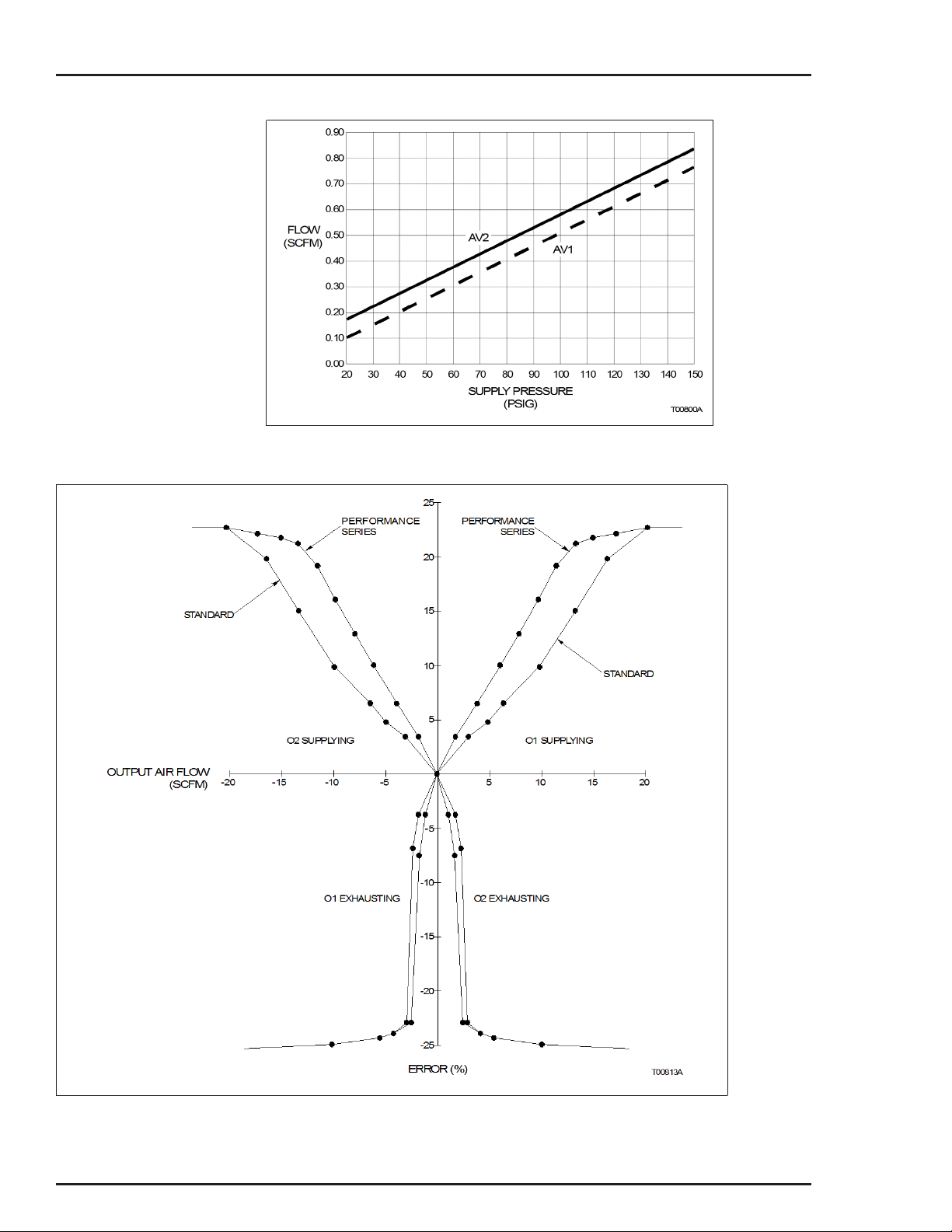
series increases this delivery capacity even more. The flow gain
curves shown in Figures 1-3 and 1-4 show output air flow versus
input error signal for the standard and high gain performance
series positioners.
DESCRIPTION
1 - 2
Page 12

Explosionproof I/P Option
INTRODUCTION
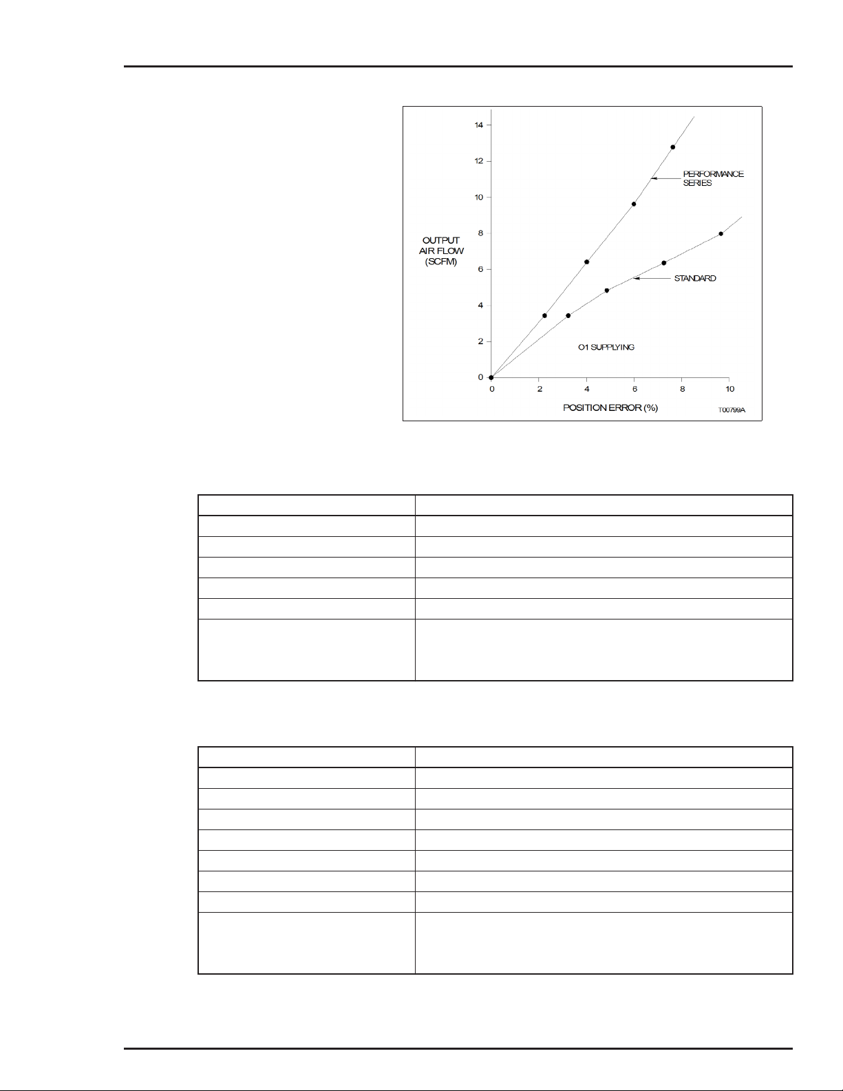
Figures 1-3 and 1-4 show that the large signal maximum air flow
for both the standard and performance series positioners is about
the same. The performance series positioners achieve maximum
flow capacity at a much smaller error signal.
NOTE: ABB does not recommend using a performance
series positioner on a small actuator, as it could cause
instability.
The Type AV27 positioner employs an explosionproof I/P converter that is mounted to an adapter block manifold. The adapter
block manifold is bolted to the outside of the main positioner housing. The unit is a Type AV12 positioner with the electric to pneumatic (four to 20-milliamp to 20.7 to 103.4-kilopascal (3.0 to
15.0-pounds per square inch gage)) conversion occurring within
the externally mounted I/P converter.
The four to 20-milliamp input signal wires shall be connected
through an explosionproof conduit entrance on the I/P converter. If
no electrical connections are made within the main housing, the
entire positioner can be considered suitable for application in the
hazardous locations shown on the I/P label.
NEMA 4X Option
APPLICATION
FEATURES
Refer to Figure 3-1 for the external and mounting dimensions of
the Type A V27 positioner.
The Type A V
To maintain the NEMA 4X classification, the positioner shall be
installed per drawing C258567 and suitable piping shall be
attached to the vent opening and vented in a manner to preclude
the entrance of water under pressure, as from a hose. Additionally, the conduit connections shall be suitable for a NEMA 4X rating.
The Type A V1 and Type A V2 Characterizable Pneumatic Positioners control the position of a pneumatic actuator.
• Trouble-Free Operation. Proven pilot valve that is quickly
removable, provides less downtime, lower maintenance costs,
increased reliability and extended performance.
______N positioner comes with a NEMA 4X housing.
• Compact Rugged Design. Die cast aluminum housing,
beam, spring arm, follower arm and 303 stainless steel pilot
APPLICATION
1 - 3
Page 13

INTRODUCTION
valve provide long life and maximum environmental protection. The compact housing increases mounting flexibility.
• Characterizable Output. Large positioning cam can be
shaped to provide desired relationship between the input signal and the actuator position.
• Accurate Calibration. Independent zero and span adjust-
ments eliminate interaction and provide fast and accurate calibration.
• Simplified Reverse Operation. Action can be changed in the
field by changing cams and reversing 01 and 02 connections.
The reverse acting cam is conveniently located on the inside
of the front cover.
• Highly Visible Position Status Indicator. A fluorescent
orange position indicator is visible through a polycarbonate
window, providing fast indication of actuator position.
• Vent Design Allows Natural Gas Operation. Vent pipe
arrangement permits operation using natural gas.
• Split Range Service. Split range capability allows sequencing
of multiple actuators using a single control signal.
• Adjustable Gain. Two levels of gain are possible by changing
the hinge springs supplied with the positioner.
• Adaptable Usage. The positioner can control both single and
double acting, linear and rotary type actuators.
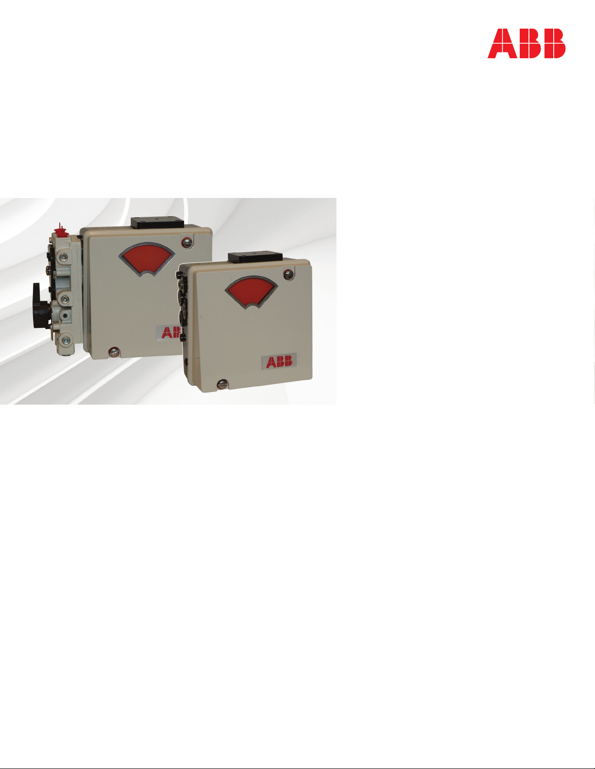
• High Capacity. More than 0.65 cubic meters per minute (23
standard cubic feet per minute) can be supplied or exhausted
at 482.6 kilopascals (70.0 pounds per square inch gage) supply pressure (Fig. 1-1).
• Continuously Adjustable Span and Zero for Each Stroke
Level. Capable of 100-percent stroke for 50-percent signal
span or 50-percent stroke for 100-percent signal span.
• Low Air Consumption. Enhanced pilot valve design and
manufacturing technique allows the Type AV positioner maximum performance with minimum air consumption (Fig. 1-2).
• Adjustable Speed Control without Additional Hardware.
Speed of actuator can be reduced to desired speed using the
pilot valve stroke adjustment screws.
FEATURES
1 - 4
Page 14

INSTRUCTION CONTENT
INTRODUCTION
This instruction includes the following sections:
Introduction
Description and
Operation
Installation
Calibration
Operating Procedures
Troubleshooting
Maintenance
Provides a description of this instruction; its sections and uses,
along with a brief description of the Type AV1 and Type AV2 positioners. This section also provides reference documents (Table
1-2), product nomenclature (Table 1-2), specifications (Tables 1-3,
1-4 and 1-5), agency approvals (Table 1-6) and positioner acces-
sories (Table 1-7). Table 1-8 lists retrofit mounting kits, Table 1-9
lists available speed control orifices, and Table 1-10 lists the available pressure gages. Table 1-11 lists pressure regulators, Table
1-12 lists supply air filters available from ABB and Table 1-13 lists
the materials used in the positioner components.
Describes the functional operation of the positioners.
Provides information about installing a Type AV positioner.
Provides calibration and adjustment procedures.
Presents information and procedures for various applications.
Provides a table containing errors, causes and corrective action.
Includes preventive maintenance information and procedures.
Repair and
Replacement
Support Services
Appendix A
Appendix B
Appendix C
Appendix D
Procedures in this section give step-by-step instructions for
removing and replacing components.
Provides recommended spare and replacement parts lists. Illustrations of both positioners provide part numbers for all major
components.
Provides calibration information about the four to 20-milliamp position transmitter and the potentiometric position transmitter.
Quick start section for control engineers that are knowledgeable
about positioners and the overall process in which the positioner is
to be used.
Details cam shaping information.
Covers the pneumatic position transmitter option.
HOW TO USE THIS INSTRUCTION
For safety reasons, read and completely understand this instruc-
tion before completing any tasks or procedures associated with
installation, calibration, operation, maintenance or repair.
INSTRUCTION CONTENT
1 - 5
Page 15

INTRODUCTION
The section arrangement of this instruction is sequential. After initial start-up and calibration, store this instruction in a safe place for
future reference.
REFERENCE DOCUMENTS
Table 1-1. Reference Documents
Number Title
ANSI/NFPA 70 National Electrical Code
CEC Canadian Electrical Code
D-AAP-UP Universal Pneumatic Rotary Actuator, Type UP (specification)
D-APE-AV1234 Characterizable Positioners, Type AV1, AV2, AV3 & AV4 (specification)
CSA c22.1 Process Control Equipment
I-E96-500 Site Planning and Preparation
I-P81-20 Universal Pneumatic Rotary Actuator, Type UP (instruction)
ANSI/ISA-7.0.01-1996 Quality Standards for Instrument Air
ISA S75.13-1989 Method of Evaluating the Performance of Positioners with Analog Input Signals and
Pneumatic Output (Instrument Society of America)
P-P88-001 Product Application Guide, Installing a Type AV Positioner in a Hazardous Location
NOMENCLATURE
Position 1 23456789
Type A V
_______
1
2
Next Page
1 20.7 to 103.4 kPa (3.0 to 15.0 psig) (Type AV1)
2 20.7 to 186.2 kPa (3.0 to 27.0 psig) (Type AV1)
3 4 to 20 mA (standard intrinsically safe Type AV2)
5 20.7 to 103.4 kPa (3.0 to 15.0 psig), high temperature applications
6 20.7 to 186.2 kPa (3.0 to 27.0 psig), high temperature applications
7 4 to 20 mA with explosionproof I/P converter (NEMA 7) (Type AV2)
1 12.7 to 50.8 mm (0.5 to 2.0 in.) or 45° rotary motion
2 25.4 to 101.6 mm (1.0 to 4.0 in.) or 90° rotary motion
Table 1-2. Nomenclature
Characterizable Positioners
Characterizable Pneumatic Positioner
Characterizable 4 to 20-mA Input Positioner (actuator moves to 0%
or 100% upon loss of signal)
Input Signal
(Type AV1)
(Type AV1)
Stroke/Rotary Motion (cam selection)
1
1
2
REFERENCE DOCUMENTS
1 - 6
Page 16

Position 1 23456789
Type A V
_______
INTRODUCTION
Table 1-2. Nomenclature (continued)
Characterizable Positioners
Prev
0 No manifold
1 Manifold with equalizing valve, filters and gage ports (required for dou-
2 Manifold with equalizing valve inoperable (includes filters and gage
3 Gage block (gage port only)
0 None (must be 0 for Types AV15, AV16 and AV27)
1 Potentiometric resistive output
2 4 to 20-mA output
0 Standard with feedback arm for linear motion
1 0.500-in. square end
2 0.342-in. square end for older DeZurik actuators
3 0.250 in. across flats (UP1 and UP2 after August, 1995)
4 0.375 in. square for DeZurik PowerRac
5 0.156 in. across flats for NAMUR rotary actuators
NOTES:
1. High temperature Type AV1 positioners are only available without manifolds or position transmitters; however, gage blocks are permitted.
2. Explosionproof Type AV2 positioners are not available with position transmitters or manifolds
3. No longer available as of October 2003..
Manifold (includes filters)/Gage Block
ble acting actuators with manual override)
3
ports)
1
Position Transmitter
Drive Shaft
®
actuators
Other Options
0 Standard (no other options)
N NEMA 4X enclosure rating (when installed per drawing C258567)
P Performance Series — high pneumatic gain for large actuators
SPECIFICATIONS
Table 1-3 provides performance specifications of the Type AV1
and Type AV2 positioners. Tables 1-4 and 1-5 provide performance specifications for the position transmitters.
Table 1-3. Type AV1/2 Positioner Specifications1
Property Characteristic/Value
Input range
AV11 and AV15 20.7 to 103.4 kPa (3.0 to 15.0 psig)
AV12 and AV16 20.7 to 186.2 kPa (3.0 to 27.0 psig)
AV23 and AV27 4 to 20 mA
Input impedance (Type AV2 only)
Nominal 215 at 22°C (72°F)
Maximum 245 at 60°C (140°F)
SPECIFICATIONS
1 - 7
Page 17

INTRODUCTION
Table 1-3. Type AV1/2 Positioner Specifications1 (continued)
Property Characteristic/Value
Standard stroke range (cam selection)
AV__1____ 12.7 to 50.8 mm (0.5 to 2.0 in.) linear, rotary input 45°
AV__2____ 25.4 to 101.6 mm (1.0 to 4.0 in.) linear, rotary input 90°
Gain 2 adjustment levels by changing gain hinge spring. Refer to the flow
gain curves as shown in Figures 1-3 and 1-4 for standard and high
gain units.
Accuracy
Resolution
Hysteresis
Repeatability
Deadband
Linearity
Supply pressure 172 to 1034 kPa (25 to 150 psig)
Supply pressure effect 0.05% per 6.9 kPa for ±69 kPa change
Capacity (maximum capacity exhausting to atmosphere)
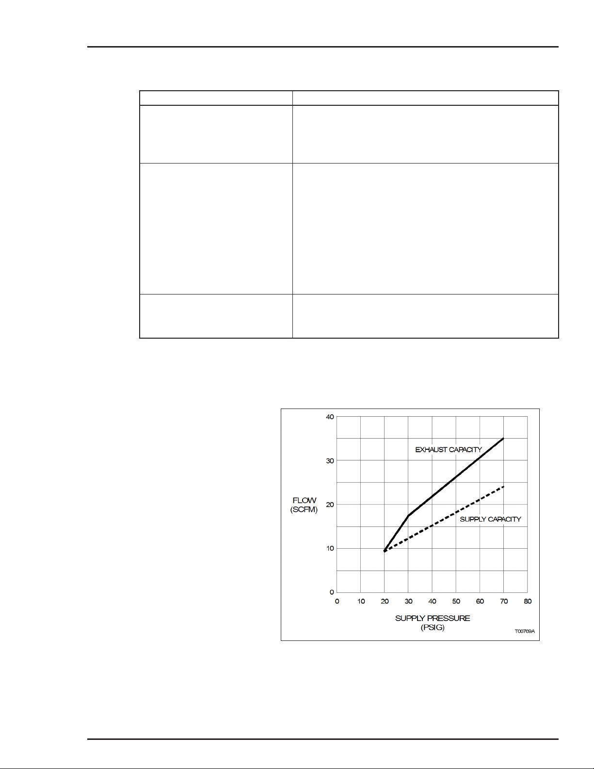
Air consumption Refer to Figure 1-2.
Vibration effect
Pneumatic connections ¼-NPT on supply, signal and output connections
Materials of construction
Enclosure classification
2
AV1 0.80% of span maximum
AV2 0.90% of span maximum
AV1 0.09% of span maximum
AV2 0.30% of span maximum
2
AV1 0.45% of span maximum
AV2 0.70% of span maximum
2
AV1 0.12% of span maximum
AV2 0.50% of span maximum
2
AV1 0.12% of span maximum
AV2 0.30% of span maximum
2
0.70% of span maximum
NOTE: Minimum supply pressure should be 34.4 kPa (5.0 psig) above operating pressure required by actuator.
(0.05% per 1.0 psi for ±10 psig change)
Refer to Figure 1-1.
2
Enclosure Aluminum and <0.5% magnesium
Pilot valve 303 stainless steel
Standard NEMA 3R classification when vent hole is protected from rain using
AV______N NEMA 4X when installed per drawing C258567.
<2.0% error for:
5 to 15 Hz at peak-to-peak constant displacement of 4 mm (0.16 in.)
15 to 120 Hz at accelerations to 2 Gs
1
-NPT on pressure gages
8
rain elbow (½-NPT street elbow, refer to Figure 3-1).
SPECIFICATIONS
1 - 8
Page 18
INTRODUCTION
Table 1-3. Type AV1/2 Positioner Specifications1 (continued)
Property Characteristic/Value
Weight
AV1 1.84 kg (4.06 lbs)
AV2 (standard) 2.32 kg (5.11 lbs)
AV2 (explosionproof) 2.95 kg (6.51 lbs)
Temperature limits
Operating
AV11/2 -40°C to 82°C (-40°F to 180°F)
AV15/6 -20°C to 127°C (-4°F to 250°F)
AV2 -20°C to 82°C (-4°F to 180°F)
Storage
AV11/2 -40°C to 93°C (-40°F to 200°F)
AV15/6 -20°C to 127°C (-4°F to 250°F)
AV2 -20°C to 82°C (-4°F to 180°F)
Humidity limits
Operating 0% to 95% noncondensing
Storage 0% to 95% noncondensing
NOTES:
1. Performance testing performed on a ABB Type UP10 actuator.
2. Tested according to ISA-S75.13-1989
3. For operation below 4.4°C (40°F), dew point of the supply air must be 10°C (18°F) lower than the lowest expected operating temperature.
SPECIFICATIONS SUBJECT TO CHANGE WITHOUT NOTICE.
3
3
3
Figure 1-1. Capacity (Exhaust to Atmosphere)
SPECIFICATIONS
1 - 9
Page 19
INTRODUCTION
Figure 1-2. Air Consumption
Figure 1-3. Output Air Flow vs. Error Signal — Standard and Performance Series
SPECIFICATIONS
1 - 10
Page 20
INTRODUCTION
Figure 1-4. Expanded First Quadrant View of Figure 1-3
Table 1-4. Type AV ____1__ Potentiometric Position Transmitter Specifications
Property Characteristic/Value
Total resistance 2000
Power rating 1 W up to 70°C (158°F), 0 W at or above 125°C (257°F)
Wiper rate of change 9.9 nominal per degree of cam rotation
Temperature effect 0.05% (500 ppm) per °C (0.03% (278 ppm) per °F) maximum
Maximum voltage 35 VDC or 30 VAC across the potentiometer ends
Temperature limits
Operating -40°C to 82°C (-40°F to 180°F)
Storage -40°C to 93°C (-40°F to 200°F)
SPECIFICATIONS SUBJECT TO CHANGE WITHOUT NOTICE.
Table 1-5. Type AV____2 __ 4 to 20-mA Position Transmitter Specifications
Property Characteristic/Value
Supply voltage 16 to 34 VDC
Output signal 4 to 20 mA
Output loading 500 at 24 VDC, 1000 at 34 VDC
Accuracy <0.6% of span (maximum)
Hysteresis <0.5% of span (maximum)
Ambient temperature effect <0.063% per °C (<0.035% per °F)
EMI/RFI effect <1.5% maximum at 10 V/m field strength, 20 to 450 MHz
Temperature limits
Operating -40°C to 82°C (-40F° to 180°F)
Storage -40°C to 93°C (-40F° to 200°F)
SPECIFICATIONS SUBJECT TO CHANGE WITHOUT NOTICE.
SPECIFICATIONS
1 - 11
Page 21

INTRODUCTION
Table 1-6. Agency Approvals1
Nomenclature Approval/Certification
AV1 and AV23 Factory Mutual Research (FM):
Approved as nonincendive for:
Class I, Division 2, Groups A, B, C and D
Class II, Division 2, Groups F and G
Class III, Division 2
Approved as intrinsically safe for:
Class I, Division 1, Groups A, B, C and D
Class II, Division 1, Groups E, F and G
Class III, Division 1
AV27__0__ Factory Mutual Research (FM):
Canadian Standards Association (CSA):
Certified as:
Class 1, Division 2, Groups A, B, C and D
Class II, Division 2, Groups E, F and G
Class III, Division 2
Certified as intrinsically safe for:
Class I, Division 1, Groups A, B, C and D
Class II, Division 1, Groups E, F and G
Class III, Division 1
Canadian Standards Association (CSA):
2
Approved as explosionproof for:
Classes I, II; Division 1, Groups B, C, D,
E, F and G
All This product complies with all applicable European Community product require-
ments, and specifically with those required to display the CE marking on the product
nameplate.
NOTES:
1. Hazardous locations approvals for use in flammable atmospheres are for ambient conditions of -25°C to 40°C (-13°F to 104°F), 86 to
106 kPa (12.5 to 15.7 psig) with a maximum oxygen concentration of 21%.
2. For installing the positioner in a hazardous location, refer to Product Application Guide, Installing a Type AV Positioner in a Hazard-
ous Location.
Certified as explosionproof for:
Classes I, II; Division 1, Groups B, C, D,
E, F and G
Table 1-7. Accessories1
Accessory Description
Mounting kits Dependent on valve stem size (Figure 9-1, kit number 5327321__). For ABB retrofit
kits, refer to Table 1-8.
Speed control
orifices
Pressure gages For reading signal, supply and output pressures (refer to Table 1-10).
Blank cam Used to characterize the positioner if the standard cams (square, linear, square root)
Supply air regulator Refer to Table 1-11.
Pneumatic position
transmitter
Air filters ABB recommends installing an air filter in the supply air line to prevent particles from
Manifold Filters For addition or replacement of secondary air filters on manifold-equipped positioners.
Bypass valve
assembly
NOTE:
1. For recommended spare parts and additional spare parts, refer to Section 9.
Regulate time constant of positioner and final control device. Orifices are installed
directly into positioner output ports (refer to Table 1-9). Speed adjustment can also be
controlled by using the internal stroke adjustment screws (refer to PILOT VALVE
STROKE ADJUSTMENT in Section 4).
will not produce the desired relationship. Blank cam must be profiled (part number
5400277_1.
Refer to Appendix D (Type AV1__0___ positioner only).
entering the positioner that can lead to malfunctions. Refer to Table 1-12 for filter part
numbers.
Kit number 258487 _1.
Part number 5326945_1. Refer to Table 9-24 and Figure 9-2.
SPECIFICATIONS
1 - 12
Page 22

INTRODUCTION
Table 1-8. Rotary Actuator Retrofit Mounting Kits
Kit Number Drive Nomenclature Retrofit Mounting Kit
5400309_1 UP1, UP2 Type AP positioner to
258493_1 UP3, UP4
258494_1 UP5, UP6
258527_1 AC0404
258528 _1 AC0608
258529 _1 AC0816
258530 _2 AC1016
258527_1 AC0404 ABB part number pilot
258528_1 AC0608
258529 _1 AC0816
258530_1 AC1016
Type AV positioner
valve positioner to Type
AV positioner
Table 1-9. Speed Control Orifices
Part Number
5327327 _1 1.02 0.04
5327327_2 Blank (drill to suit) Blank (drill to suit)
NOTE:
1. Speed control can also be obtained by internal positioner adjustment. Refer to PILOT VALVE
STROKE ADJUSTMENT in Section 4.
mm in.
Size
1
Table 1-10. Pressure Gages
Part Number Legend
5326605 _4 Instrument 0 to 200 0 to 30
5326605 _5 Supply
5326605_6 Output 0 to 1,000 0 to 160
NOTE:
1. The optional manifold provides gage ports, one for instrument (internal input signal), and two output gages. A supply gage can be installed in the supply line (piping by customer).
kPa psig
1
0 to 1,000 0 to 160
Range
Table 1-11. Supply Air Regulators with Gages
Part Number
1951029 _5 125 250 ¼ NPT
Max. Outlet
Pressure (psig)
Max. Inlet
Pressure (psig)
Inlet/Outlet
Connections
Table 1-12. Supply Air Filters
Max. Inlet
Part Number
5328563 _2 250 121.0 125.0 ¼ NPT
NOTE:
1. In-line coalescing filter for removal of solid and liquid contaminants in compressed air. Filter
comes with universal mounting bracket and grade 6 filter that is 99.97% efficient at 0.3 micron. Part
number 5328563 _2 has a zinc bowl.
Pressure
(psig)
Max. Temperature Inlet/Outlet
°C °F
1
Connection
Size
SPECIFICATIONS
1 - 13
Page 23

INTRODUCTION
Table 1-13. Component Material List
Component Material
Housing Aluminum
Cover Aluminum
Inserts Lamond (thermoplastic elstomer)
®
Window Lexan
Screws Stainless steel
Range spring 302 stainless steel
Pilot valve (stem and body) 303 stainless steel
Gain hinge spring 302 stainless steel
Cam 302 stainless steel
Cam shaft 303 stainless steel
Bearings Bronze
Cam follower arm Aluminum
Bearing Stainless steel
Shaft 303 stainless steel
Spring arm Aluminum
Zero adjustment nut Aluminum
Indicator Valox
terphthalate)
Tubing Silicone
Drive arm Aluminum
®
washers Teflon
Teflon
Fasteners Steel/stainless steel
Signal connector Nylon
Diaphragms
All except Types AV15 and AV16 Buna-N with Dacron fabric
Types AV15 and AV16 Fluorosilicone with Dacron fabric
Diaphragm plastic parts Rynite
Gage block (optional) Aluminum
O-rings
All except Types AV15 and AV16 Buna-N
Types AV15 and AV16 Viton
Manifold (optional) Aluminum
Adhesive Epoxy
Handle Rynite
Plate Aluminum
Plug Stainless steel
Valve Aluminum
Valve handle Rynite
phthalate
(polycarbonate)
®
— unreinforced (polybutylene
®
(FR-530) polyethylene ter-
®
SPECIFICATIONS
1 - 14
Page 24

Table 1-13. Component Material List
Component Material
Position transmitter (optional)
(AV____1/2 __)
Gears Delrin
Gear hub Brass
Additional Type AV2 components
1
Regulator
Regulator bracket
Tubing Nylon
I/P converter Copper
1
Polysulfone
304 stainless steel
Copper clad glass laminate
Monel
Nickel-iron
Noryl
Polyethylene
Polyester magnet wire
Rare earth magnet
Zinc
INTRODUCTION
®
(coolymer acetal)
1
1
®
405
®
(phenylene ether/phenylene)
NOTE:
1. Regulator not applicable for AV2s after July, 2001.
SPECIFICATIONS
1 - 15
Page 25

Page 26
INTRODUCTION
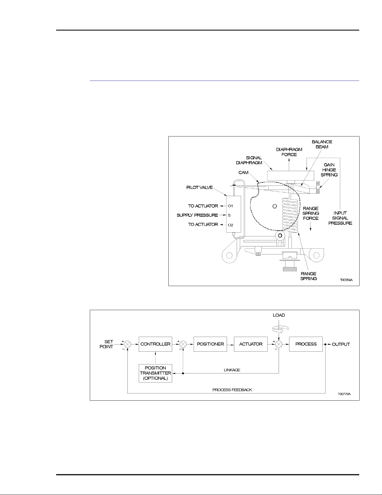
SECTION 2 - DESCRIPTION AND OPERATION
This section describes and explains the functional and physical
operation of Type AV1 and AV2 positioners. Figure 2-1 diagrams
the operating principles of the positioners. Figure 2-2 shows the
placement of a positioner in a typical control system.
Figure 2-1. Operation Diagram
Figure 2-2. Block Diagram
INTRODUCTION
2 - 1
Page 27

DESCRIPTION AND OPERATION
FUNCTIONAL OPERATION
Type AV positioners operate by balancing opposing forces. Figure
2-1 shows a diagram of the Type AV positioner. A balance beam,
hinged at one end and connected to the pilot valve at the other, is
acted upon by two forces:
• Upward force of the signal diaphragm assembly.
• Downward force from the range spring.
The input signal pressure determines the diaphragm force. The
Type AV1 positioner uses an external input pressure (either 20.7
to 103.4 kilopascals (3.0 to 15.0 pounds per square inch gage) or
20.7 to 186.2 kilopascals (3.0 to 27.0 pounds per square inch
gage)). The Type AV2 positioner uses a current to pneumatic converter to generate the input signal pressure.
The range spring force is a function of the shape and position of
the cam. The cam is coupled to the cam shaft that is connected
through linkage (or coupling) to the actuator. Therefore, range
spring tension is a function of the actuator position.
A change in input signal changes the force exerted by the signal
diaphragm, moving the balance beam, in turn moving the pilot
valve. The pilot valve supplies and/or exhausts air to the actuator
that ultimately changes its position. The change in actuator position is fed back to the positioning cam. The positioning cam
moves, changing the tension of the range spring until a balanced
condition once again exists.
The positioner is normally located in a control loop (Fig. 2-2)
between the controller and the actuator.
Actuator position is fed back to the positioner for comparison with
the position commanded by the input control signal (direct signal
pressure or a current value). For linear motion actuators, the feedback mechanism consists of:
• A drive rod that follows the motion of the actuator.
• An adjustable-length, swivel-ended connecting link that trans-
mits the motion of the drive rod to an adjustable drive arm on
the positioner.
• A camshaft and cam that are rotated through an angle by the
drive arm. A function of the cam is to permit characterization of
actuator position versus input signal.
FUNCTIONAL OPERATION
2 - 2
Page 28

INTRODUCTION
SECTION 3 - INSTALLATION
Several applications are possible using a Type AV positioner. The
steps for installing a Type AV positioner are in sequence in this
section. After installation is complete, refer to Section 4 for calibration information.
• Unpack and inspect the equipment.
• Mount the positioner.
• Connect tubing to the positioner.
• Connect wiring to the positioner.
NOTES:
1. For application in a hazardous location, refer to ABB Product Application Guide, Installing a Type AV Positioner in a
Hazardous Location.
2. Appendix B provides a quick start guide for the Type AV
positioner. It is intended for control engineers having extensive
experience in the use and application of pneumatic positioners.
The quick start guide highlights the major points of installation
and calibration. Detailed installation and calibration information
is contained in this section and in Section 4.
Select an installation method that provides a fail safe mode
upon loss of controller signal. Certain installation methods
WARNING
UNP ACKING AND INSPECTION
do not stroke the equipment to a fail safe condition upon
loss of controller signal. Failure to select a fail safe installation method could cause injury to personnel and damage to
equipment.
1. Check for obvious damage to the shipping carton.
2. Open the carton and remove all loose packing.
3. Carefully remove the positioner from the carton and inspect for
any physical damage that may have occurred during shipping.
4. Remove the two cover screws and the positioner cover and
examine the interior for any loose components such as nuts,
screws, springs, etc. Check the data on the nameplate to be certain the positioner type ordered for the application was received.
INTRODUCTION
3 - 1
Page 29

INSTALLATION
5. If the positioner is suitable for the application and appears
undamaged, install the cover and proceed with the installation
instructions.
6. If storing the positioner prior to installation, leave it in the original carton, if possible. Store in an area free from corrosive vapors
and extremes in temperature and humidity.
7. Do not store the positioner in an area that would take it out of
the specifications listed in Tables 1-3, 1-4 and 1-5.
ENCLOSURE CLASSIFICATION
The standard enclosure for the Type AV1 and Type AV2 positioners conform to NEMA 3R when a ½-14 NPT street elbow (Fig. 3-1)
is installed into the vent hole on the housing. The elbow prevents
water or other liquid from entering the enclosure. The position of
the elbow is related to the mounting plane of the positioner in its
service location. The elbow must be positioned to face downward.
The NEMA 3R version meets the extended corrosion resistance
requirements of NEMA 250.
A NEMA 4X version is available as an option (Type AV______N
positioners). To maintain the NEMA 4X classification, the positioner shall be installed per drawing C258567 and suitable piping
shall be attached to the vent opening and vented in a manner to
preclude the entrance of water under pressure, as from a hose.
Additionally, the conduit connections shall be suitable for a NEMA
4X rating.
MOUNTING CONSIDERATIONS
Choose a location for the positioner based on the following factors:
• Access to the internal positioner adjustments — the mounting
location should provide enough room to remove the cover in
order to perform calibration and repair and replacement procedures inside the positioner. Refer to Figure 3-1 for positioner
dimensions. Figure 3-2 shows the electrical connections, Figure 3-3 shows the dimensions of the drive arm connections
and Figure 3-4 shows the drive shaft variations.
• Allow room for linkage to the actuator — the mounting position
should be such that a practical linkage arrangement can be
made between the positioner and the actuator for full range
travel.
ENCLOSURE CLASSIFICATION
3 - 2
Page 30
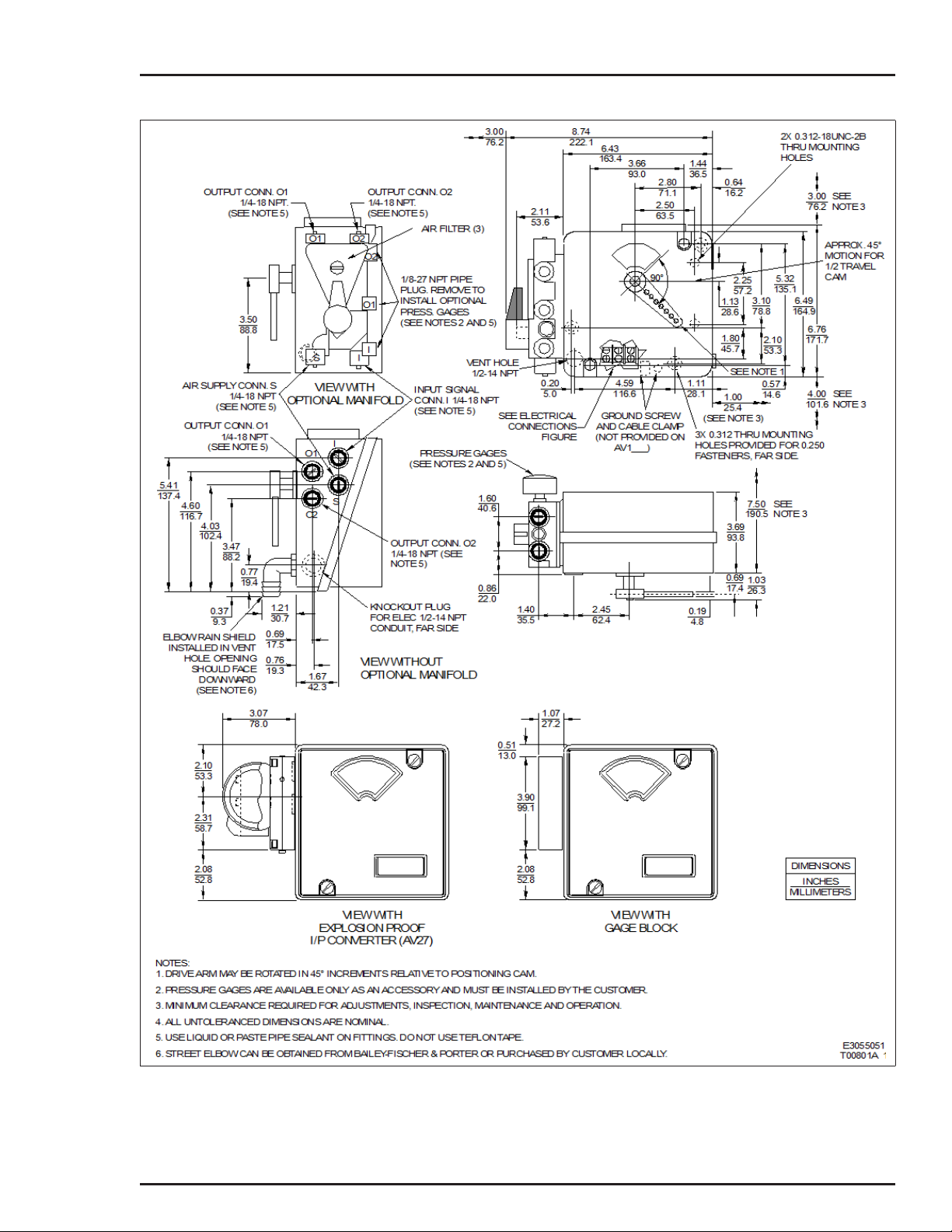
INSTALLATION
Figure 3-1. External and Mounting Dimensions
MOUNTING CONSIDERATIONS
3 - 3
Page 31

INSTALLATION
Figure 3-2. Electrical Connections
NOTE: For Type AV27, the 4-20 mA input signal wires shall be
connected through an explosion-proof conduit entrance directly
to the I/P converter.
MOUNTING TYPE AV POSITIONERS
The Type AV positioner can be used with double acting or single acting
actuators. Mounting and external dimensions are shown in Figure 3-1.
Figure 3-5 shows a typical mounting arrangement using a ABB mounting
kit. Refer to Figure 9-23 for an exploded view and complete parts list of
Figure 3-3. Drive Arm Connections
MOUNTING TYPE AV POSITIONERS
3 - 4
Page 32

INSTALLATION
the kit. If using the positioner with a rotary actuator, the positioner can be
directly connected to the actuator, as shown in Figure 3-6.
NOTE: If the actuator is equipped with a Type AV positioner as
ordered, verify that all the connections are secure and make any
adjustments as required.
Figure 3-4. Drive Shaft Variations
Figure 3-5. Mounting Using Linkage (Typical)
MOUNTING TYPE AV POSITIONERS
3 - 5
Page 33

INSTALLATION
WARNING
Figure 3-6. Mounting Using Direct Coupling (Typical)
Due to the wide range of applications that the Type AV positioner
is suited for, we can only provide general information about
mounting. Use the following procedure to mount the positioner.
Before mounting or installing positioner, check nameplate
data to make certain positioner is suitable for application
desired. DO NOT AT ANY TIME EXCEED THE RATINGS
LISTED ON THE NAMEPLATE.
1. Set the actuator at the zero position. Connect the adjustable
linkage to the drive arm. The drive arm holes correspond to stroke
length of the actuator. Refer to Figure 3-3 for the stroke length for
each drive arm hole.
2. Install the cam (black, direct acting; or red, reverse acting) that
will provide the required direction of rotation.
A direct acting (black) positioning cam with segments A, B and C
(Fig. 3-7) and a reverse acting cam are furnished with each positioner. The reverse acting cam has red radial lines and arcs and
is stored on the inside of the positioner cover. Cam A is for a
square root function, cam B is for linear motion and cam C is for a
MOUNTING TYPE AV POSITIONERS
3 - 6
Page 34

INSTALLATION
square function (Table 3-1). Cam B is in place when the positioner
is shipped from the factory. The cams may be shaped to conform
to special applications. Refer to Appendix C for information about
cam shaping.
NOTE: If the application is reverse acting, the reverse acting
cam (red radial lines) must be installed and the connections to
ports 01 and 02 must be reversed.
Figure 3-7. Cam
Table 3-1. Cam Characteristics
Positioning
Cam
Any Stroke
A
B
C
The cam, camshaft and drive arm rotate as an assembly. Cam
motion is 90 degrees (Type AV__2____) or 45 degrees (Type
AV__1____) depending on the positioner type specified by
nomenclature (Figure 3-7).
Each cam shape (A, B or C) has its own eight-point center hole for
mounting on the camshaft (Fig. 3-7). Place the cam in one of the
eight 45-degree positions so that the midpoint of the cam corresponds to the mid stroke of the actuator. The drive arm should be
perpendicular to the motion of the actuator with the actuator at mid
stroke.
3. Adjust the connecting linkage so that the zero radial line on
the cam intersects the center of the cam roller when the actuator
is at its zero position (Fig. 3-8).
Piston or Valve Position (P)
vs
Control Signal (I)
Square root
Linear
Square
IP=
IP=
2
IP
=
Figure
Number
C-1
C-2
C-3
MOUNTING TYPE AV POSITIONERS
3 - 7
Page 35

INSTALLATION
4. Lock all linkage components in place.
TUBING CONNECTIONS
Air Supply Pressure
CAUTION
Air Supply Filtering
Figure 3-8. Cam Roller Alignment
Type AV positioners are available with (Type AV___1___ and
A V___2___) or without (AV___0 ___) manifolds. The following outlines supply air information and describes the piping connections.
Do not exceed the maximum supply pressure of 1034 kilopascals (150 pounds per square inch gage). Exceeding this
pressure could cause equipment damage.
The air supply pressure range is 172 to1034 kilopascals (25 to
150 pounds per square inch gage).
NOTE: The minimum supply pressure should be 34.4 kilopascals (5 pounds per square inch gage) above the operating pressure required by the actuator.
An external filter is recommended for Type AV positioners for primary filtration of the supply air. ABB provides supply air filters as
accessories. Refer to Table 1-12 for part numbers.
NOTE: Primary air supply filters are recommended for positioners with a manifold (AV___1/2___), without a manifold
(AV___0___) or with a gage block (AV___3___).
TUBING CONNECTIONS
3 - 8
Page 36

Positioners equipped with manifolds have three secondary filters
as part of the unit. If the filters become clogged, they can be
cleaned (by removing and reverse flushing with air or liquid) or
replaced (refer to Table 1-7 for kit number). Refer to Section 7 for
manifold filter replacement procedures.
Air Supply Quality (Recommended)
For long-term, trouble free operation, it is recommended that the
supply air be of instrument quality and conform to the ANSI/
ISA-7.0.01-1996 standard that includes the following:
INSTALLATION
Tubing Connections
• The pressure dew point as measured at the dryer outlet shall
be at least 10
which any part of the instrument air system is exposed. The
pressure dew point shall not exceed 4
sure.
• The oil content should be as close to zero as possible and,
under no circumstances, shall it exceed one (1) ppm w/w or
v/v.
• Instrument air should be free of corrosive contaminants and
hazardous gases, which could be drawn into the instrument air
supply.
In addition, the particle size in the supply line should not be
greater that 3.0 microns.
o
C (18oF) below the minimum temperature to
o
C (39oF) at line pres-
1. Connect the required air supply to connection S (Fig. 3-9).
NOTE: Use liquid or paste pipe sealant to seal the connection.
Maximum torque for ¼-NPT fittings is 13.6 Nm (10 ft-lbs).
Figure 3-9. Port Locations
TUBING CONNECTIONS
3 - 9
Page 37

INSTALLATION
2. Based on the positioner type, perform one of the following
steps (Fig. 3-9):
AV11 or AV15: Connect 20.7 to 103.4-kPa (3.0 to 15.0-psig)
instrument signal to connection I.
AV12 or AV16: Connect 20.7 to 186.2-kPa (3.0 to 27.0-psig)
instrument signal to connection I.
AV2: Connection I is not used and should be plugged. If it is
not plugged, do so at this time.
3. Connect the output ports 01 and 02 as required to provide the
desired direction of rotation. Figures 3-10, 3-11, 3-12 and 3-13
show single acting tubing examples, and Figure 3-14 shows a
double acting tubing example. Air pressure to the 01 port
increases from zero toward full supply as the control signal (error)
increases. Air pressure to the 02 port decreases from full supply
toward zero as the control signal increases.
NOTE: The tubing arrangements shown in Figures 3-10, 3-11,
3-12, 3-13 and 3-14 are typical examples and may not reflect the
arrangement required for the application.
1
4. -NPT permanent instrument gages can be installed into the
8
gage ports for calibration requirements.
WIRING TYPE AV2 POSITIONER
Use the following procedure to wire the Type AV2 positioner:
1. Connect the four to 20-mA position demand signal wires to
terminals TB1-4 (+) and TB1-5 (-) of the terminal block (Figs. 3-2
and 3-15). For Type AV27 positioners, unscrew the I/P cover and
make the four to 20-mA connections to the positive (+) and negative (-) terminals. If installing a Type AV2 ___0__ positioner, go to
Step 4.
NOTE: If using a twisted shielded pair for signal wiring, ground
one end of the shielded pair at the source. Trim the other end of
the pair, located inside the enclosure, so that bare wires are not
exposed.
2. If equipped with an optional 4 to 20-mA position transmitter
(AV2 ___2__), connect a 24-VDC power supply in series with the
required output load (Table 1-7) to terminals TB1-1 (+) and TB1-2
(-).
3. If equipped with an optional potentiometric position transmitter
(Type AV2___1__), connect a power supply (maximum 35 VDC or
30 VAC) across TB1-1 and TB1-3. Use the signal across TB1-1
and TB1-2 or TB1-2 and TB1-3 for position transmitter feedback.
WIRING TYPE AV2 POSITIONER
3 - 10
Page 38

INSTALLATION
Refer to Appendix A for detailed information about position transmitters.
NOTE: Route the wiring inside the positioner so it does not
become entangled with moving parts. A cable clamp (Figs. 3-1
and 4-1) is provided inside the positioner so entanglement can
be avoided.
Figure 3-10. Direct Acting, Top Loaded,
Single Acting Tubing Example
4. Grounding positioners should be done in accordance with
local electrical codes (in U.S, National Electrical Code, ANSI/
NFPA 70. In Canada, Canadian Electrical Code, CSA c22.1). A
grounding screw is provided inside the enclosure for grounding,
denoted by .
NOTES:
1. The grounding screw located inside the enclosure is a safety
ground and should not be used to ground the shielded pair.
2. The positioner must be grounded to avoid ground loop
conditions.
WIRING TYPE AV2 POSITIONER
3 - 11
Page 39

INSTALLATION
Figure 3-11. Reverse Acting, Top Loaded,
Single Acting Tubing Example
Figure 3-12. Direct Acting, Bottom Loaded,
Single Acting Tubing Example
WIRING TYPE AV2 POSITIONER
3 - 12
Page 40

INSTALLATION
WIRING TYPE AV1 POSITIONER
This section applies to the following positioners:
• Type A V1___1__ .
• Type A V1___2__.
NOTES:
1. If this is a Type AV1___0__ positioner, no electrical wiring is
required.
2. If using a twisted shielded pair for signal wiring, ground one
end of the shielded pair at the source. Trim the other end of the
pair, located inside the enclosure, so that bare wires are not
exposed.
1. If equipped with an optional 4 to 20-mA position transmitter
(Type AV1___2__), connect a 24-VDC power supply in series with
the required output load (Table 1-5) to terminals TB1-1 (+) and
TB1-2 (-) (Figs. 3-2
information about position transmitters.
Figure 3-13. Reverse Acting, Bottom Loaded,
Single Acting Tubing Example
and 3-15). Refer to Appendix A for detailed
2. If equipped with an optional potentiometric position transmitter
(Type AV1___1__), connect a power supply (maximum 35 VDC or
30 VAC) across TB1-1 and TB1-3. Use the signal across TB1-1
and TB1-2 or TB1-2 and TB1-3 for position transmitter feedback.
WIRING TYPE AV1 POSITIONER
3 - 13
Page 41

INSTALLATION
Figure 3-14. Double Acting Tubing Example
Figure 3-15. Wiring Connections
WIRING TYPE AV1 POSITIONER
3 - 14
Page 42

INSTALLATION
Refer to Appendix A for detailed information about position transmitters.
NOTE: Route the wiring inside the positioner so it does not
become entangled with moving parts. A cable clamp (Fig. 3-1 or
4-1) is provided inside the positioner so entanglement can be
avoided.
3. Grounding positioners should be done in accordance with
local electrical codes (in U.S, National Electrical Code, ANSI/
NFPA 70. In Canada, Canadian Electrical Code, CSA c22.1). A
grounding screw is provided inside the enclosure for grounding,
denoted by .
NOTES:
1. The grounding screw located inside the enclosure is a safety
ground and should not be used to ground the shielded pair.
2. The positioner must be grounded to avoid ground loop
conditions.
RADIO FREQUENCY INTERFERENCE
Most electronic equipment is influenced by radio frequency interference (RFI). Caution should be exercised with regard to the use
of portable communications equipment in the area.
ABB recommends posting appropriate signs in the plant. Refer to
the Site Planning and Preparation instruction for additional information on RFI.
WIRING REQUIREMENTS
Under ideal conditions, the use of conduit and shielded wire may
not be required. However, to avoid noise problems, it is recommended that wiring be enclosed in conduit. Just prior to entering
the housing, rigid conduit should be terminated and a short length
of flexible conduit should be installed to reduce any stress.
RADIO FREQUENCY INTERFERENCE
3 - 15
Page 43

Page 44

INTRODUCTION
SECTION 4 - CALIBRATION
This section contains the following information:
• Calibration.
• Gain adjustment.
• Speed control.
• Troubleshooting calibration.
NOTES:
1. All procedures in this section assume direct acting operation.
2. The troubleshooting calibration procedure in this section is
not required for normal operation. The procedure is used only
when operating difficulties occur. The corrective action column of
Table 6-1 indicates when to use the troubleshooting calibration.
3. Calibration can also involve cam shaping to achieve the
required control characteristics. Refer to Appendix C for detailed
information about the cam.
CALIBRATION
Tools required:
Zero Adjustment
3
-inch Allen wrench.
32
Mechanical linkage is performed during installation (Section 3)
that normally consists of adjusting the connection between the
positioner and actuator so that the mechanical zero on the positioning cam corresponds to the mechanical zero of the actuator.
The calibration procedure detailed here involves fine adjustments
to the zero and span such that the input signal will cause the
desired travel.
Calibration consists of applying an input signal pressure to the
positioner to set the zero and span. These adjustments are made
with the supply air applied to the positioner.
Type AV positioners have position transmitter options that are
available for feedback purposes. Refer to Appendix A for more
information about the position transmitter options.
The positioner zero adjustment sets the tension on the range
spring and adjusts the input signal level that causes the actuator
to move off of the minimum travel stop. The zero percent radial
line of the cam should align with the center of the cam roller (Fig.
4-2).
INTRODUCTION
4 - 1
Page 45

CALIBRATION
Use the following steps to adjust the zero:
1. Depending on the nomenclature type, apply one of the following input signals:
T ype AV1
T ype AV2
20.7 kPa (3.0 psig) input signal pressure. The actuator should
move to its fully closed position.
4.0 mA input signal. The actuator should move to its fully closed
position.
2. To adjust the zero, loosen the zero adjustment set screw (Fig.
4-1) with the -inch Allen wrench.
3. Turn the zero adjustment nut (clockwise moves the actuator
toward minimum span) until the zero radial line on the cam intersects with the center of the cam roller (Fig. 4-2).
NOTE: This adjustment may be biased; i.e., turning the zero
adjustment nut slightly clockwise to make sure a valve or
damper is firmly seated at the minimum input signal.
4. Tighten the zero adjustment set screw.
3
32
Figure 4-1. Calibration Adjustments
CALIBRATION
4 - 2
Page 46

Span Adjustment
CALIBRATION
Figure 4-2. Cam Roller Alignment
T ypes AV1 1/5
T ype AV12/6
T ype AV2
Setting the span normally requires the alignment of the 100 percent radial line of the cam with the center of the cam roller.
Use the following steps to adjust the span:
1. Depending on the nomenclature type, apply one of the following input signals:
Apply 103.4 kPa (15.0 psig). The actuator should move to its
fully opened position.
Apply 186.2 kPa (27.0 psig). The actuator should move to its
fully opened position.
Apply 20 mA. The actuator should move to its fully opened
position.
2. To adjust the span, loosen the span adjustment screw (Fig.
4-1) using a -inch Allen wrench.
3. Slide the span adjustment assembly (Fig. 4-1) in the appropriate direction until the actuator moves to align the 100% radial line
with the center of the cam roller (toward pilot valve increases span
of actuator).
3
32
4. Tighten the span adjustment screw.
CALIBRATION FOR PARTICULAR APPLICATION
The following positioner adjustments may be used to tailor the
operation of the actuator to meet application requirements.
CALIBRATION FOR PARTICULAR APPLICATION
4 - 3
Page 47

CALIBRATION
Zero Adjustment
The positioner zero adjustment can be used to set initial tension
on the range spring so that the actuator will not begin to move
from its minimum position until it receives an input signal between
zero and 50 percent (Fig. 4-3). This application of suppression is
useful when two or more actuators are to be operated in
sequence; where the actuator is equipped with a minimum stop; or
where the characteristics of the device that the actuator is moving
must be matched with the characteristics of another regulated
device.
Span Adjustment
Figure 4-3. Zero Adjustment Graph
The span adjustment affords a variation of actuator motion for a
given span of input signal. For example, the span may be adjusted
to allow full actuator travel to occur with a signal change as small
as 50 percent of its full span (e.g., split ranging) (Fig. 4-4). At the
other extreme, the span adjustment can be set to produce as little
as 50 percent of the travel capability of the actuator over the full
input signal pressure span (e.g., short stroking).
This flexibility in span adjustment is useful when the device being
regulated is oversized, since the adjustment allows operation of
the actuator or cylinder through its useful motion for desired full
change in control signal pressure. It is also useful in matching the
signal versus position characteristics of the actuator or cylinder
with the characteristics of related power devices in the same control system.
CALIBRATION FOR PARTICULAR APPLICATION
4 - 4
Page 48
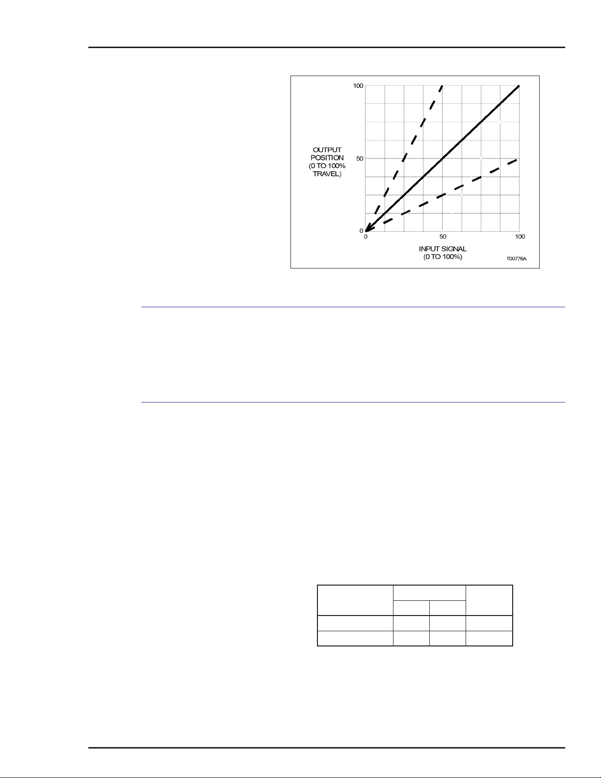
GAIN AND SPEED ADJUSTMENTS
CALIBRATION
Figure 4-4. Span Adjustment Graph
Gain Adjustment
Gain and speed adjustment information applies to both the Type
AV1 and Type AV2 positioners. This is the gain of the overall positioner. The factory-installed 0.25-millimeter (0.100-inch) gain
hinge spring suits most applications. This adjustment is not a
mandatory part of calibration.
Gain adjustment on the Type AV positioners is accomplished by
changing the gain hinge spring (Item 7, Figs. 9-3 or 9-4) connecting the beam assembly to the positioner housing. Provided with
each positioner are two different gain hinge springs. If actuator
oscillation occurs, the overall positioner gain may be too high.
Positioner gain is related to the thickness of the gain hinge spring.
Gain decreases as the thickness of the gain hinge spring
increases. Refer to Table 4-1 for hinge information.
For information on changing the gain hinge spring, refer to Gain
Hinge Spring in Section 8.
5400264 _ 1
5400264 _ 2 0.76 0.030 Medium
NOTES:
1. For small actuators, it may be necessary to combine both
gain hinge springs.
2. The high gain hinge spring comes installed from the factory.
Table 4-1. Gain Hinge Springs1
Part Number
2
Thickness
mm in.
0.25 0.010 High
Gain
GAIN AND SPEED ADJUSTMENTS
4 - 5
Page 49

CALIBRATION
Speed Adjustment
Speed adjustment is not normally required when calibrating a
positioner. Type AV positioners come from the factory adjusted for
maximum operating speed. However, the speed of operation can
be reduced in two ways. Speed control orifices can be used to
slow positioner operation or a speed adjustment can be made
internal to the positioner to change operating speed.
When the system involves only a single actuator, a high positioning speed is usually an advantage. However, in a complex control
system, it is generally desirable to operate all power devices at the
same speed in order to avoid interaction between units and consequently undesirable process conditions.
ORIFICE
If it is necessary to reduce the speed of operation, 1.02-millimeter
(0.04-inch) speed control orifices are available as an option from
ABB. These orifices are installed directly into the output ports (01
and 02) of the positioner and have ¼-NPT ports for connecting
tubing from the actuator. If these orifices are too small (causing
the actuator to respond too slowly) they may be drilled out to
obtain desired speed control. Blank orifices are also available.
Refer to Table 1-9 for orifice part numbers.
PILOT VALVE STROKE ADJUSTMENT
If it is necessary to reduce the speed of operation, a pilot valve
stroke adjustment can reduce the speed and does not require
additional hardware. This adjustment limits the pilot valve stroke.
The pilot valve stroke is measured by the movement (displacement) of the pilot valve stem, as shown in Figure 4-5. Figure 4-5
shows the maximum stroke length that is also the maximum
speed of operation and is how the positioner comes from the factory. Use the following procedure to reduce the speed of operation:
NOTE: Never adjust the pilot valve for a stroke greater than
0.762 millimeters (0.030 inches) in either direction. A greater
stroke will reduce the performance of the positioners.
1. Use a -inch Allen wrench to turn the top adjustment screw
clockwise -turn to reduce stroke time (Fig. 4-6). ABB suggests
1
8
-turn increments. Take note of the number of turns. In total, do
not exceed one full turn (clockwise) from the factory setting (Fig.
4-5). This adjustment controls the amount of air going to port 01.
3
32
1
8
GAIN AND SPEED ADJUSTMENTS
4 - 6
Page 50

Figure 4-5. Pilot Valve Adjustment
CALIBRATION
2. Use a -inch Allen wrench (the wrench must be at least
5-inches long) to turn the lower adjustment screw clockwise the
same amount as the top adjustment screw to insure speed of
operation is the same in both directions (if desired). Be careful
when accessing the lower adjustment screw. Insert the Allen
wrench up through the bottom of the range spring (Fig. 4-6). This
adjustment controls the amount of air going to port 02.
NOTE: To adjust the pilot valve stroke to the factory setting, refer
to PILOT VALVE STROKE ADJUSTMENT in Section 8.
3. Test for satisfactory stroke time and adjust as required.
3
32
Figure 4-6. Speed Adjustment Screws
GAIN AND SPEED ADJUSTMENTS
4 - 7
Page 51

CALIBRATION
TROUBLESHOOTING CALIBRATION ADJUSTMENTS
The I/P converter of the Type AV2 positioner comes from the factory completely calibrated. Use the following procedures only
when operating difficulties occur. The corrective action column
of Table 6-1 indicates when to use the troubleshooting calibration.
The purpose of this procedure is to adjust the I/P converter so that
a four to 20-milliamp input signal will produce a 20.7 to 103.4-kilopascal (3.0 to 15.0-pounds per square inch gage) signal. Use the
following procedure to adjust the I/P converter. The supply air
must be connected to the positioner for this procedure.
Tools Required:
CAUTION
• Digital voltmeter.
• Calibrated 0 to 30-psig instrument gage.
• Small screwdriver.
• Current source.
Do not exceed the maximum supply pressure of 1034 kilopascals (150 pounds per square inch gage). Exceeding this
pressure could cause equipment damage.
1. Connect the calibrated zero to 30-psig instrument gage or
other accurate pressure measuring device to the I port to monitor
the signal pressure during calibration.
2. Turn on the supply air to the positioner.
3. Provide a four-mA signal to the I/P converter and observe the
output pressure. If the pressure equals 20.7 kPa (3.0 psig) go to
Step 5. If the pressure does not equal 20.7 kPa (3.0 psig) go to
Step 4.
4. Adjust the zero screw 0 on the bottom of the I/P con-
verter (Fig. 4-7) until the output pressure equals 20.7 kPa (3.0
psig). Clockwise rotation increases pressure.
5. Apply a 20-mA signal to the I/P converter and observe the output pressure. If the pressure equals 103.4 kPa (15.0 psig) go to
Step 7. If the pressure does not equal 103.4 kPa (15.0 psig) go to
Step 6.
6. Adjust the span screw ( on the bottom of the I/P con-
verter (Fig. 4-7) until the output pressure equals 103.4 kPa (15.0
psig). Clockwise rotation increases pressure.
7. Repeat Steps 3 through 6 until the 20.7 kPa (3.0 psig) and
103.4 kPa (15.0 psig) outputs are attained with four and 20-mA
signal inputs.
TROUBLESHOOTING CALIBRATION ADJUSTMENTS
4 - 8
Page 52

CALIBRATION
Figure 4-7. I/P Adjustment
TROUBLESHOOTING CALIBRATION ADJUSTMENTS
4 - 9
Page 53

Page 54

SECTION 5 - OPERATING PROCEDURES
INTRODUCTION
This section details the equalizing valve of the optional manifold
(Type AV___ 1___ positioner).
NOTE: This section only applies when the positioner is equipped
with a manifold assembly.
EQUALIZING AND AIR SUPPLY SHUTOFF VALVE
The equalizing valve, supplied with the manifold assembly, allows
the actuator to be manually or automatically operated. By turning
the valve handle to MAN, supply pressure to the positioner is cut
off and the 01 and 02 ports are tied together, allowing manual
repositioning of the actuator.
NOTE: It is important to understand that the equalizing valve is
not a bypass valve. Be aware that if the actuator is not secured
before transferring the valve handle of the manifold, the actuator
will move.
Lock the actuator in place or be aware of the possible move-
WARNING
ment before moving the equalizing valve to MAN or AUTO.
Failure to do so could result in injury to personnel.
Transfer from Automatic to Manual Operation
1. Manually lock the actuator or final control element.
2. If equipped with a manifold and equalizing valve, push in the
valve handle and turn it to the MAN position.
3. If not equipped with a manifold and equalizing valve, turn off
the supply air.
NOTE: If there are no means of locking the actuator or final control element, it will move in the direction of the process or
mechanical load when the supply air is turned off.
Transfer from Manual to Automatic Operation
1. Verify that the valve handle is in the MAN position.
INTRODUCTION
5 - 1
Page 55

OPERATING PROCEDURES
2. If the manual operator does not lock the actuator in position:
a. The piston must be positioned from prior knowledge of the
actuator position versus signal or the actuator may jump when
transferred to automatic.
b. Push the valve handle in and turn it to the AUTO position.
3. If the manual operator locks the actuator in position:
a. Depress the valve handle and turn it to the AUTO position.
The actuator will oppose the manual operator if the drive position and input signal do not correspond.
b. Manually operate the actuator until the load on the manual operator decreases. If the output pressure gages are
installed on the positioner, the gage readings should equalize.
NOTE: If, in Step 3, it is desired that the drive stay in its initial
position, the input signal must be adjusted to correspond with
the drive position as indicated by the load on the manual operator, output pressure gages or prior knowledge of position versus
input signal.
EQUALIZING AND AIR SUPPLY SHUTOFF VALVE
5 - 2
Page 56

INTRODUCTION
WARNING
Error Probably Cause Corrective Action
Oscillation of
actuator
Actuator at one end
of stroke and does
not respond to input
change
SECTION 6 - TROUBLESHOOTING
This section provides information about the Type AV positioner
when operating difficulties are encountered. A table listing errors,
probably causes and corrective actions allows the operator to
troubleshoot a problem pertaining to the positioner.
If a problem occurs and is traced to the positioner, check the supply pressure, input and output connections, and mechanical
adjustments before removing it from service.
Disconnect the supply signal source or remove the equipment from the process before servicing. Failure to do so
can cause unexpected movement posing a risk of bodily
injury.
Table 6-1. Positioner Errors
Drive arm not
securely attached to
actuator.
Pneumatic signal
leak.
Pilot valve sticking. Remove pilot valve and clean or replace. Refer to Pilot Valve
Gain too high. Change gain hinge spring to greater thickness. Refer to Gain
Air lines in wrong
ports.
Incorrect cam
installed for application.
Pneumatic signal
leak.
Mechanical calibration shift.
I/P converter not
functioning.
Tighten or correct linkage as necessary.
Check for leaks in connectors or fittings.
Assembly in Section 8.
Hinge Spring in Section 8.
Check air line connections (Figs. 3-10, 3-11, 3-12, 3-13 and
3-14).
Determine application (reverse or direct acting) and check for
correct cam (Figs. 3-10, 3-11, 3-12, 3-13 and 3-14).
AV1: Check input signal connection for leaks at I port.
AV2: Check signal at I port. If pressure is between 20.7 and
103.4 kPa (3.0 and 15.0 psig) and responds to input signal
change then problem exists elsewhere.
If pressure is not between 20.7 and 103.4 kPa (3.0 and
15.0 psig) or does not respond to input change, check for
leaks inside positioner and check I/P converter calibration
(refer to TROUBLESHOOTING CALIBRATION ADJUST-
MENTS in Section 4).
Make sure the linkage between positioner and actuator is tight
and has no backlash.
Check I/P converter calibration (refer to TROUBLESHOOT-
ING CALIBRATION ADJUSTMENTS in Section 4).
INTRODUCTION
6 - 1
Page 57

TROUBLESHOOTING
Table 6-1. Positioner Errors
Error Probably Cause Corrective Action
Excessive air consumption (exhaust
loud)
Slow response Signal diaphragm
Full range cannot be
obtained with
mechanical zero and
span adjustment
Leakage at the joint
of the manifold
assembly (if
equipped).
Pilot valve body seal
is leaking.
Tubing discon-
nected.
leaking.
I/P converter out of
calibration or not
functioning.
Signal diaphragm
leaking.
I/P converter out of
calibration or not
functioning.
I/P converter is
defective.
Remove manifold and check O-rings. Refer to Manifold in
Section 8.
Remove pilot valve body and check O-rings. Refer to Pilot
Valve Assembly in Section 8.
Check connection at pressure regulator and I/P converter.
Replace signal diaphragm. Refer to Diaphragm Assembly in
Section 8.
Calibrate I/P converter. Refer to TROUBLESHOOTING CALI-
BRA TION ADJUSTMENTS in Section 4. If unable to cali-
brate, replace I/P converter. Refer to I/P Converter in
Section 8.
Replace diaphragm. Refer to Diaphragm Assembly in
Section 8.
Calibrate I/P converter. Refer to TROUBLESHOOTING CALI-
BRA TION ADJUSTMENTS in Section 4. If unable to cali-
brate, replace I/P converter. Refer to I/P Converter in
Section 8.
Replace I/P converter. Refer to I/P Converter in Section 8.
INTRODUCTION
6 - 2
Page 58

INTRODUCTION
The reliability of any stand-alone product or control system is
affected by the maintenance of the equipment. ABB recommends
that all equipment users practice a preventive maintenance program that will keep the equipment operating at an optimum level.
Maintenance personnel should be familiar with the Type AV positioner and have experience working with process control applications that use pneumatic positioners.
System maintenance must be performed only by qualified
personnel and only after securing the equipment controlled
WARNING
PREVENTIVE MAINTENANCE SCHEDULE
by the circuit. Altering or removing components from an
active circuit may upset the controlled process leading to
personnel injury and equipment damage.
Table 7-1 is the preventive maintenance schedule and checklist
for Type AV positioners. The table lists the preventive maintenance tasks in groups according to their specified maintenance
interval. The maintenance intervals are recommendations and
may vary depending on the location environment and the air quality of the positioner. As a minimum, these recommended maintenance tasks should be performed during an extended process
shutdown.
SECTION 7 - MAINTENANCE
Some tasks in Table 7-1 are self-explanatory. Instructions for tasks
that require further explanation are covered under PREVENTIVE
MAINTENANCE PROCEDURES.
Table 7-1. Preventive Maintenance Schedule
Preventive Maintenance Tasks
Check and tighten all wiring connections.
Clean or replace supply air filter.
Clean or replace manifold filters. Refer to procedure.
7 - 1
Interval
(months)
12
INTRODUCTION
Page 59

MAINTENANCE
Table 7-1. Preventive Maintenance Schedule (continued)
Preventive Maintenance Tasks
Check all air connections for leakage while positioner
is under pressure. Use a soapsuds solution.
Check the signal diaphragm for leaks. use a soapsuds
solution.
Clean pilot valve and stem with low residue solvent.
Refer to REP AIR AND REPLACEMENT in Section 8.
Check calibration of positioner and actuator. Refer to
Section 4.
Check and verify that there is no backlash in the linkage/connections between the positioner and the actuator. Refer to Section 3.
PREVENTIVE MAINTENANCE PROCEDURES
This section covers instructions for cleaning and replacing the
manifold filters.
MANIFOLD FILTERS
Tools Required:
• Torque screw driver.
Interval
(months)
12
WARNING
Lock the actuator in place or be aware of the possible movement before moving the equalizing valve to MAN or AUTO.
Failure to do so could result in injury to personnel.
1. Transfer the positioner from automatic to manual operation
(Section 5).
2. After allowing the pressure to bleed off, remove the cover
screw securing the filter cover (Fig. 7-1) and set the cover screw
and cover aside.
3. Clean or replace the filters.
a. To clean the filters, soak them in a low residue solvent.
After soaking, spray the filters thoroughly using compressed
air until they are free of particles and solvents.
b. Insert the clean or new filters, using the filter kit identified
in Table 1-7, into the filter wells.
4. Replace and lubricate the three O-rings (Fig. 7-2) using the
lubricant supplied in the kit (Dow Corning
®
No. 4).
5. Clean and place the cover over the filters and replace the
cover screw. Torque the cover screw to two Nm (18 in-lbs).
PREVENTIVE MAINTENANCE PROCEDURES
7 - 2
Page 60

MAINTENANCE
6. Transfer the positioner back to automatic operation
(Section 5).
Figure 7-1. Positioner with Manifold
Figure 7-2. Manifold with Filter
Cover Removed
MANIFOLD FILTERS
7 - 3
Page 61

Page 62

SECTION 8 - REPAIR AND REPLACEMENT
INTRODUCTION
This section provides procedures that detail removal and replacement of positioner components.
Disconnect the supply signal source or remove the equip-
WARNING
REPLACEMENT PROCEDURES
ment from the process before servicing. Failure to do so
can cause unexpected movement posing a risk of bodily
injury.
This section contains replacement procedures for:
• Manifold.
• Gain hinge spring.
• Pilot valve assembly.
• I/P converter.
• Cam.
• Diaphragm assembly.
Manifold
Tools Required:
• Torque screwdriver.
5
• -inch Allen wrench.
32
1. Secure (lock) the actuator and remove the supply air.
2. If equipped with an equalizing valve, push in on the valve handle
and move it to the MAN position (Fig. 8-1).
3. Remove the four Allen screws that secure the manifold (Fig.
8-1).
4. Lift the manifold off the positioner.
5. Before replacing the manifold, make sure there are no deposits
on the bosses of the positioner or on the back of the manifold. If there
are, remove the deposits.
6. Replace the O-rings or clean them if they are in good condition
(Fig. 8-2).
7. Clean the O-ring grooves and apply Dow Corning No. 4 or equivalent lubricant to the O-rings.
INTRODUCTION
8 - 1
Page 63

REPAIR AND REPLACEMENT
8. Place the manifold in place on the positioner so it properly seats
on the bosses.
9. Insert the Allen screws and torque them to 3.5 Nm (31 in.-lbs).
Not all of the Allen screws are the same length. Be sure each screw
mates correctly.
10. To replace the filters and filter cover, refer to MANIFOLD FIL-
TERS in Section 7.
Gain Hinge Spring
Tools Required:
Figure 8-1. Positioner with Manifold
NOTES:
1. Refer to Table 4-1 for gain hinge spring part numbers.
2. Item numbers in this procedure reference Figure 9-3 or 9-4.
• Flat-tip screwdriver.
9
• -inch Allen wrench.
64
1. Transfer the positioner from automatic to manual operation
(Section 5).
2. Remove the positioner cover by removing the two cover screws.
3. Remove the plug button (Item 29) from the positioner housing.
This opening provides access to the screws.
REPLACEMENT PROCEDURES
8 - 2
Page 64

REPAIR AND REPLACEMENT
Pilot Valve Assembly
Figure 8-2. Manifold O-Rings
4. Remove the four hinge screws (Item 42) while holding the beam
assembly steady (Item 6). Remove the two screws that connect the
beam to the hinge first.
5. Remove the gain hinge spring.
6. Insert the new gain hinge spring.
NOTE: When installing the gain hinge spring, be sure it properly
seats (flush) between the steps. If the gain hinge spring hangs
up, remove and rotate the hinge 90. Check for proper seating.
7. Insert and torque the screws to 2.6, 0.2 Nm (23, 2 in.-lbs) while
holding the beam assembly steady (Item 6). Insert the two screws
that secure the hinge to the housing first.
8. Transfer the positioner back to automatic operation (Section 5).
9. Perform the procedure outlined in PILOT VALVE STROKE
ADJUSTMENT.
NOTES:
1. Refer to Section 9 for pilot valve assembly kit numbers.
2. Item numbers in this procedure reference Figure 9-3 or 9-4.
REPLACEMENT PROCEDURES
8 - 3
Page 65

REPAIR AND REPLACEMENT
Tools Required:
Flat-tip screwdriver.
1. Transfer the positioner from automatic to manual operation
(Section 5).
2. Remove the positioner cover by removing the two cover screws.
3. Carefully unhook the ends of the valve clip (Item 5). Remove the
valve clip from the valve body. Remove the valve stem (Item 3) from
the lower end of the valve body.
4. Remove the two pilot valve screws (Item 52) securing the valve
body and lift the valve body off the housing.
5. Replace the O-rings. Clean the O-ring grooves and apply Dow
Corning No. 4 or equivalent lubricant to the O-rings.
6. Set the (replacement or clean) valve body in place.
7. Secure the valve body by replacing and tightening the pilot valve
screws to 2.6, 0.2 Nm (23, 2 in.-lbs).
8. Make certain the valve stem is clean. Install the valve stem.
9. Install the valve clip.
I/P Converter
Tools Required:
10. Transfer the positioner back to automatic operation (Section 5).
11. Perform the procedure outlined in PILOT VALVE STROKE
ADJUSTMENT.
NOTES:
1. Refer to Section 9 for I/P converter part numbers.
2. Item numbers in this procedure reference Figure 9-4.
3. This procedure only applies to Type AV2 positioners.
• Flat-tip screwdriver.
• T15 Torx.
• Pliers.
1. Transfer the positioner from automatic to manual operation
(Section 5).
2. Remove the positioner cover by removing the two cover screws.
3. Remove the two wires that connect the I/P converter (Item 80) to
the termination assembly (Item 59).
4. Loosen the three screws (Item 58) securing the I/P bracket.
REPLACEMENT PROCEDURES
8 - 4
Page 66

Cam
REPAIR AND REPLACEMENT
5. Slide the I/P converter out from under the screws and remove it
from the housing.
6. Disconnect the two air lines from the I/P converter. When replacing the I/P converter, remove the portion of the air line tubing that was
connected to the I/P converter or replace the tubing. If this is not
done, particles from the tubing can cause a blockage.
7. Reverse the preceding steps to install the new I/P converter.
NOTE: Item numbers reference Figure 9-3.
Tools Required:
• Flat-tip screwdriver.
• Adjustable wrench.
• Pliers.
1. Transfer the positioner from automatic to manual operation
(Section 5).
2. Remove the positioner cover by removing the two cover screws.
3. Remove the indicator screw (Item 51) and indicator (Item 19).
4. Hold and stop the cam shaft from rotating if it is not secured by
linkage or coupling. Using the adjustable wrench, remove the cam nut
(Item 30) and washer (Item 55).
5. Lift the cam from the cam shaft.
6. To replace the cam, determine which cam mounting hole (A, B or
C) is appropriate for the application, and set the cam on the shaft.
Make certain the star-shaped hole engages squarely on the shaft.
Refer to Figure 3-8 to align the cam.
7. Replace the cam washer and nut and tighten.
8. Set the indicator on the cam shaft and insert and tighten the
screw.
9. Transfer the positioner back to automatic operation (Section 5).
Diaphragm Assembly
NOTES:
1. Refer to Section 9 for diaphragm assembly kit numbers.
2. Item numbers in this procedure reference Figure 9-3 or 9-4.
REPLACEMENT PROCEDURES
8 - 5
Page 67

REPAIR AND REPLACEMENT
DIAPHRAGM ASSEMBL Y REMOV AL
Tools Required:
• Allen wrench.
• Adjustable wrench.
1. Transfer the positioner from automatic to manual operation
(Section 5).
2. Using an Allen wrench, remove the four diaphragm cover screws
(Item 45) and remove the diaphragm cover.
3. Remove the diaphragm support screw (Item 53) and washer
(Item 54).
NOTE: When removing the diaphragm support screw, do not
allow the diaphragm support (Item 23) to rotate.
NOTE: Item 53 is replaced by SEM screw NBMHA13006A as of
November 23, 2009/Serial Number 3K620000029936 & Item 54
is no longer used.
4. Remove the diaphragm support (Item 23).
5. Carefully remove the large diaphragm (Item 73) from assembly.
6. Remove the diaphragm spacer (Item 22).
7. Remove the diaphragm ring (Item 24).
8. Carefully remove the small diaphragm.
DIAPHRAGM ASSEMBL Y REPLACEMENT
1. Place the small diaphragm (Item 20) in the diaphragm housing
with the concave side facing up. Check for correct alignment of
the tabs relative to the diaphragm housing.
2. Place the diaphragm ring (Item 24) over the small diaphragm
(Item 20). Make sure the alignment pins on the diaphragm ring properly engage the other mating parts.
3. Set the diaphragm spacer in place (Item 22).
4. Place the large diaphragm (Item 73) in place with the convex side
up. Check for correct alignment of the tabs relative to the diaphragm
housing.
5. Place the diaphragm support (Item 23) on the large diaphragm.
REPLACEMENT PROCEDURES
8 - 6
Page 68

REPAIR AND REPLACEMENT
6. Replace the washer (Item 54) and screw (Item 53). Torque the
screw to 0.35 Nm (50 in.-oz.) while securing the diaphragm support
(Item 23) so it does not rotate.
NOTE: Item 53 is replaced by SEM screw NBMHA13006A as of
November 23, 2009/Serial Number 3K620000029936 & Item 54
is no longer used.
7. Inspect the diaphragm assembly for distortion. If distortion occurs
loosen the screw (Item 53), straighten the diaphragm and tighten
while holding Item 23 still.
8. Replace the diaphragm cover (Item 25) and screws (Item 45).
Make certain the diaphragm cover is properly seated. Torque the
cover screws uniformly to 0.9 Nm (8 in.-lbs).
9. Transfer the positioner back to automatic operation (Section 5).
10. Apply the input signal pressure and check for leaks around the
diaphragm assembly using soapsuds solution.
11. Perform the procedure outlined in PILOT VALVE STROKE
ADJUSTMENT.
PILOT VALVE STROKE ADJUSTMENT
The purpose of this adjustment is to keep the valve stem in the
proper operating range. This procedure should be used in conjunction with the following procedures:
• Gain Hinge Spring.
• Pilot Valve Assembly.
• Diaphragm Assembly.
NOTE: For internal speed adjustment refer to PILOT VALVE
STROKE ADJUSTMENT in Section 4.
When the valve stem is in the balance position, as shown in Figure 8-3, the stem is flush with both ends of the valve body. There
are two adjustment screws to adjust. Use the following procedure
to check and adjust the travel of the valve stem:
Tools required:
3
• -inch Allen wrench (standard length).
32
3
• -inch Allen wrench (long length — at least five inches).
32
1. With the positioner cam at approximately 50%, manually lock
the actuator in position by:
a. Using manual override if available.
- or -
PILOT VALVE STROKE ADJUSTMENT
8 - 7
Page 69

REPAIR AND REPLACEMENT
b. If manual override is not available, disconnect (and
secure) the linkage. Plug ports 01 and 02 if necessary.
2. Apply the supply pressure.
3. Apply the maximum input signal to the positioner:
• AV11: 103.4 kPa (15.0 psig).
• AV12:186.2 kPa (27.0 psig).
• AV23: 20 mA.
4. Use the long -inch Allen wrench, adjust the top adjustment
screw (Fig. 8-4) appropriately until the measurement matches the
value shown in Figure 8-3. Figure 8-3 also shows the way the measurement is taken.
5. Apply the minimum input span to the positioner:
• AV11: 20.7 kPa (3.0 psig).
• AV12: 20.7 kPa (3.0 psig).
• AV23: 4 mA.
6. Use the long -inch Allen wrench to adjust the lower stroke
adjustment screw (Fig. 8-4). Adjust the screw until the measurement
matches the value shown in Figure 8-3.
3
32
3
32
Figure 8-3. Pilot Valve Measurement for Maximum Speed
PILOT VALVE STROKE ADJUSTMENT
8 - 8
Page 70

REPAIR AND REPLACEMENT
Figure 8-4. Stroke Adjustment Screws
PILOT VALVE STROKE ADJUSTMENT
8 - 9
Page 71

REPAIR AND REPLACEMENT
PILOT VALVE STROKE ADJUSTMENT
8 - 10
Page 72

INTRODUCTION
SECTION 9 - SUPPORT SERVICES
This section provides:
Recommended spare
parts
Additional spare parts
Positioner illustrations
RECOMMENDED SPARE PARTS
A list of the parts that should be kept on hand so that if malfunctions occur, replacements are quickly accessible.
A list of parts that can be ordered for replacement.
Illustrations that point out all major components of the Type AV1
and AV2 positioners. A parts list is included along with part numbers.
ABB suggests that the following items be kept on hand in case
replacement is necessary. To order, call your nearest ABB sales
representative; supply the kit numbers or if the items are not of a
kit, supply the part numbers.
NOTE: This is not a complete list of available parts; refer also to
in this section and Table 1-7 in Section 1.
Table 9-1. Shutoff Valve Kit No. 258270_1
Description Part No. Quantity
Shutoff valve 5400060_1 1
(positioners equipped with optional
manifold, Type AV___ 1/2 ___ )
Table 9-2. AV Diaphragm Assembly Kit No. 258486_1 1
Item Part No. Qty Description Item Part No. Qty Description
20 5400288 _2 1 Small diaphragm 24 5400294 _1 1 Diaphragm ring
22 5400292_1 1 Diaphragm
23 5400293 _1 1 Diaphragm
23 5400293_2 1 Diaphragm
9 - 1
(for Types AV11 and AV12)
73 5400288_1 1 Large diaphragm
spacer
73 5400283_3 1 Large diaphragm
support (AV11)
support (AV12)
NOTE:
ber 2009/Serial Number 3K620000029936.
1
Kit contains SEM screw NBMMA13006A as of Novem-
(AV11)
(AV12)
INTRODUCTION
Page 73

SUPPORT SERVICES
Table 9-3. AV Diaphragm Assembly Kit No. 258486_2
Item Part No. Qty Description Item Part No. Qty Description
20 5400288_5 1 Small diaphragm 24 5400294_1 1 Diaphragm ring
22 5400292_ 1 1 Diaphragm
23 5400293_ 1 1 Diaphragm
23 5400293_2 1 Diaphragm
(for Types AV15 and AV16)
73 5400288_4 1 Large diaphragm
spacer
73 5400283_6 1 Large diaphragm
support (AV15)
support (AV16)
NOTE: 1 Kit contains SEM screw NBMMA13006A as of Novem-
ber 2009/Serial Number 3K620000029936.
Table 9-4. Filter Replacement Kit No. 258487_1
(positioners equipped with optional manifold, Type AV ___1/2___)
Part No. Qty Description
19984 _ 1 1 O-ring lubricant
5311428_1 3 O-rings
5400057 _1 3 Filters
1
(AV15)
(AV16)
Table 9-5. Pilot Valve Assembly Kit No. 258488_1
Item Part No. Qty Description
3 5400259_1 1 Valve stem
4 5400260 _1 1 Valve body
5 5400261_1 1 Valve clip
35 1951398 _12 3 O-rings
— 19984_1 1 O-ring lubricant
Table 9-6. Pilot Valve Assembly Kit No. 258488_ 2
Item Part No. Qty Description
3 5400259_1 1 Valve stem
4 5400260_1 1 Valve body
5 5400261_1 1 Valve clip
35 1951779_ 010 3 O-rings
— 19984_1 1 O-ring lubricant
(for Types AV11, AV12 and AV2)
(for Types AV15 and AV16)
RECOMMENDED SPARE PARTS
9 - 2
Page 74

SUPPORT SERVICES
Table 9-7. Pilot Valve Assembly Kit No. 258488_3
(for Types AV11 ___P, AV12 ___P and AV2___P)
Item Part No. Qty Description
3 5400259_ 1 1 Valve stem
4 5400260_2 1 Valve body
5 5400261_1 1 Valve clip
35 1951398 _12 3 O-rings
— 19984_1 1 O-ring lubricant
ADDITIONAL SPARE PARTS
Table 9-8. Pilot Valve Assembly Kit No. 258488_4
Part No. Qty Description
5400281_1 1 Forward acting full rise cam, 90° rotation
5400281_2 1 Reverse acting full rise cam, 90° rotation
5400289_1 1 Forward acting half rise cam, 45° rotation
5400289_ 2 1 Reverse acting half rise cam, 45° rotation
(for Types AV15 _0/3__ P and AV16_0/3__P)
Item Part No. Qty Description
3 5400259_1 1 Valve stem
4 5400260_2 1 Valve body
5 5400261_1 1 Valve clip
35 1951779_ 010 3 O-rings
— 19984 _ 1 1 O-ring lubricant
Table 9-9. Cam
(select appropriate cam type)
Table 9-10. AV2 I/P Assembly Kit No. 258651_1
Part No. Qty Application Description
258651_1 1 AV2 I/P converter kit
Table 9-11. Gain Hinge Springs1
Item Part No. Qty
7 5400264 _1
5400264 _2 1 0.76 0.030 Medium
NOTES:
1. For small actuators, it may be necessary to combine both gain hinge springs.
2. The high gain hinge spring comes installed from the factory.
2
1 0.25 0.010 High
Thickness
mm in.
Gain
ADDITIONAL SPARE PARTS
9 - 3
Page 75

SUPPORT SERVICES
(replaces 5400282_ 1 or 5400282 _ 2 (for replacement or field addition, Type AV ___1/2 ___))
Item Part No. Qty Description Item Part No. Qty Description
17 5400282
64 5311428_207 4 Manifold O-rings — 19984_1 1 O-ring lubricant
65 NTJHA09030 4 Manifold washers — 5400066_1 1 Valve plate
66 NBAHA16020 4 Manifold screws
NOTE:
1. Used to make equalizing valve handle inoperable for Type AV___2 ___positioner applications. Discard for Type
AV1__1 ___positioner applications.
Item Part No. Qty Description Item Part No. Qty Description
1 5400254
2 5400255
3 5400256
_ 1 1 Manifold assembly 67 NBAHA16024 2 Manifold screws
_1 1 Cover 4 5400257_ 1 1 Cover insert
_1 1 Window 5 5400257 _ 2 1 Cover insert
_ 1 1 Gasket 6 1964033 _ 1 1 Styleplate
Table 9-12. Manifold Assembly Kit No. 258491 _1
1
Table 9-13. Cam Follower Arm Kit No. 258544 _ 1
(replaces part no. 5400306 _ 1)
Part No. Qty Description
258544_1 1 Cam Follower- Arm Assembly
Table 9-14. Cover Assembly Kit No. 258545 _ 1
(for Types AV11, AV12 and AV2 — replaces part no. 5400258 _ 1)
Table 9-15. Cover Assembly Kit No. 258545 _1
(for Types AV15 and AV16 — replaces part no. 5400258 _ 1)
Item Part No. Qty Description Item Part No. Qty Description
1 5400254
2 5400255
4 5400257
Item Part No. Qty Description Item Part No. Qty Description
1 5400318
2 NKJHA16004 3 Set screw, socket
5 1951041_
_1 1 Cover 5 5400257 _ 2 1 Cover insert
_1 1 Window 6 1964033_ 1 1 Styleplate
_ 1 1 Cover insert 10 R9025-0046 1 Silicon tubing
Table 9-16. Gage Block Assembly Kit No. 258569 _1
(for replacement or field addition, Types AV11 _3 , AV12 _3 and AV2 __ 3)
_ 1 1 Manifold, gage 6 5311428_ 207 4 O-rings
hex hdlss cup pnt
4 2 Pipe plug, socket
head
7 NBAHA16020 3 Screw, hex socket
head cap
8 NTJHA09030 3 Lockwasher,
spring
ADDITIONAL SPARE PARTS
9 - 4
Page 76

SUPPORT SERVICES
Table 9-17. Gage Block Assembly Kit No. 258569 _3
(for replacement or field addition, Types AV15 _ 3 and AV16 )_3 )
Item Part No. Qty Description Item Part No. Qty Description
1 5400318
2 NKJHA16004 3 Set screw, socket
5 1951041
_1 1 Manifold, gage 6 1951779 _207 4 O-rings
7 NBAHA16020 3 Screw, hex socket
hex hdlss cup pnt
_4 2 Pipe plug, socket
head
8 NTJHA09030 3 Lockwasher,
head cap
spring
(for potentiometric position transmitters (Type AV ____1__))
Part No. Qty Description
6639540_ 1 1 Potentiometer assembly
Table 9-19. 4 to 20-mA Position Transmitter Circuit Board
Table 9-18. Potentiometer
(Type AV____2 __)
Part No. Qty Description
6639479_
1 1 Circuit board
Table 9-20. Positioner Mounting Kit Number 5327321_121
Valve Stem Diameter 0.375 to 0.750 in. (Fig. 9-1)
Item Part Number Description Item Part Number Description
1 5400266_ 1 Positioner mounting bracket 12 197120_5 Nut, elastic stop (2 req)
2 0.250-20 x 0.750 Screw, socket head (3 req) 13 5311690 _1 Adjustable stud, 2.69 in.
3 0.250 Lock washer, reg spring (3 req) 14 5311690_2 Adjustable stud, 3.43 in.
5 0.312-18 x 0.625 Cap screw, hex socket head (2 req) 21 0.375 Lock washer, med spring (3 req)
6 0.312 Lock washer, reg spring (2 req) 22 0.375-24 Nut, hex jam
7 R6440-005 Type 347 stainless steel wire, 0.300
diameter, 6-in. length
2
19934 _ 248 Spacer 25 5311691 _ 1 Clamp plate, 0.375 - 0.750-in. dia
8
2
0.190-32 x 1.125 Screw, pan head machine 27 0.375-16 x 1.50 Screw, hex skt head cap (2 req)
9
10 5312449_ 4 Connecting link, 12-in. length (cut to
fit)
3
0.190-32 x 0.875 Screw, pan head machine (2 req) 29 0.125 dia x 0.750 Groove pin, type 1
11
NOTES:
1. Positioner mounting kits for direct or reverse acting diaphragm actuators and single or double acting piston actuators with linear (reciprocating)
motion.
2. When fastening Item 10 to the drive arm at the first hole (nearest the drive shaft), use Items 8 and 9 and omit one of Item 11.
23 5311687 _ 2 Stem clamp, 0.375 - 0.750-in. dia
28 0.375-16 Nut, hex jam (2 req)
ADDITIONAL SPARE PARTS
9 - 5
Page 77

SUPPORT SERVICES
Table 9-21. Positioner Mounting Kit Number 5327321_131
Valve Stem Diameter 0.750 to 1.000 in. (Fig. 9-1)
Item Part Number Description Item Part Number Description
1 5400266 _1 Positioner mounting bracket 1130.190-32 x 0.875 Screw, pan head machine (2 req)
2 0.250-20 x 0.750 Screw, socket head (3 req) 12 197120 _ 5 Nut, elastic stop (2 req)
3 0.250 Lock washer, reg spring (3 req) 14 5311690 _ 2 Adjustable stud, 3.43 in.
5 0.312-18 x 0.625 Cap screw, hex socket head (2 req) 21 0.375 Lock washer, med spring (3 req)
6 0.312 Lock washer, reg spring (2 req) 22 0.375-24 Nut, hex jam
7 R6440-005 Type 347 stainless steel wire, 0.300
diameter, 6-in. length
2
19934 _ 248 Spacer 26 5312471 _ 1 Clamp plate, 0.750 - 1.00-in. dia
8
2
0.190-32 x 1.125 Screw, pan head machine 27 0.375-16 x 1.50 Screw, hex skt head cap (2 req)
9
10 5312449 _ 4 Connecting link, 12-in. length (cut to
fit)
NOTES:
1. Positioner mounting kits for direct or reverse acting diaphragm actuators and single or double acting piston actuators with linear (reciprocating)
motion.
2. When fastening Item 10 to the drive arm at the first hole (nearest the drive shaft), use Items 8 and 9 and omit one of Item 11.
Table 9-22. Positioner Mounting Kit Number 5327321 _ 141 (for use on Fisher Actuators)
Item Part Number Description Item Part Number Description
1 5400266 _ 1 Positioner mounting bracket 11
2 0.250-20 x 0.750 Screw, socket head (3 req) 12 197120 _ 5 Nut, elastic stop (2 req)
3 0.250 Lock washer, reg spring (3 req) 15 5319500 _ 11 Drive stud, 4.59 in.
5 0.312-18 x 0.625 Cap screw, hex socket head (2 req) 16 5319500 _ 1 Drive stud, 3.43 in.
6 0.312 Lock washer, reg spring (2 req) 17 5328155 _ 1 Stud bracket
7 R6440-005 Type 347 stainless steel wire, 0.300
diameter, 6-in. length
2
19934 _ 248 Spacer 19 1218-00 Lock washer, shakeproof (2 req)
8
2
0.190-32 x 1.125 Screw, pan head machine 20 5319524 _ 1 Lock washer, star
9
10 5312449 _ 4 Connecting link, 12-in. length (cut to
fit)
NOTES:
1. Positioner mounting kits for direct or reverse acting diaphragm actuators and single or double acting piston actuators with linear (reciprocating) motion.
2. When fastening Item 10 to the drive arm at the first hole (nearest the drive shaft), use Items 8 and 9 and omit one of Item 11.
Valve Stem Diameter 0.375 to 0.750 in. (Fig. 9-1)
24 5312483 _ 1 Stem clamp, 0.750 - 1.00-in. dia
29 0.125 dia x 0.750 Groove pin, type 1
2
0.190-32 x 0.875 Screw, pan head machine (2 req)
18 0.312-18 x 0.500 Screw, hex head cap (2 req)
ADDITIONAL SPARE PARTS
9 - 6
Page 78

SUPPORT SERVICES
Figure 9-1. Mounting Kits
Table 9-23. Rotary Actuator Retrofit Mounting Kits
Kit Number Drive Nomenclature Retrofit Mounting Kit
5400309
258493
258494
258527
258528
258529
258530
258527
258528
258529
258530
_1 UP1, UP2 Type AP positioner to
_1 UP3, UP4
_1 UP5, UP6
_1 AC0404
_1 AC0608
_1 AC0816
_2 AC1016
_1 AC0404 ABB part number pilot
_1 AC0608
_1 AC0816
_1 AC1016
Type AV positioner
valve positioner to Type
AV positioner
ADDITIONAL SPARE PARTS
9 - 7
Page 79

SUPPORT SERVICES
Table 9-24. Bypass Valve Assembly (Optional)
Parts List (Part No. 5326945 _1 — Fig. 9-2)
Item Part Number Description
1 5327226
2 5326946
3 195159
4 195727
5 195171
6 1962833
7 NBZAC16006 Screw, pan head
8 NTJAC09030 Lock washer
9 NLMAC16000 Nut, hex
10 1951041
_1 3-way valve
_1 Air line connection assy
_3 Elbow connector
_2 Brass nipple
_3 Wheatherhead tee
_1 Designation plate
_1 Sch pipe plug
Figure 9-2. Bypass Valve Assembly
ADDITIONAL SPARE PARTS
9 - 8
Page 80

SUPPORT SERVICES
Table 9-25. Type AV1 Positioner Parts List for Figure 9-3
Item Part No. Description Item Part No. Description
1 5400253 _3 Housing 46 197865 _ 2 Stroke adjustment screw
2 Refer to Table 9-26 Cover assembly 47 197865 _ 1 Stroke adjustment screw
3 5400259 _ 1 Valve stem 48 NKJHA16004 Zero adjustment set screw
4 Refer to Table 9-26 Valve body 49 NBAHA16020 Span adjustment screw
5 5400261 _ 1 Valve clip 50 Form MP481-494 Label, CSA/FM
6 5400263 _ 1 Beam assembly 51 NIDHA13005 Indicator screw
7 5400264 _ 1 Hinge 52 NIDHA15012 Pilot valve screw (2 req)
8 258544_ 1 Cam follower arm assembly 53 NBMHA13006 Diaphragm support screw
9 5400271 _ 1 Spring arm 54 NTCHA07000 Diaphragm support scr washer
10 5400272 _ 1 Pivot 55 NTGHA10000 Cam washer
11 5400273 _ 1 eyebolt 56 NTJHA09030 Span adjustment washer
12 5400275 _ 1 Retaining nut 57 Fm MP432-889 Label, indicator
13 Refer to Table 9-27 Cam 58 197893 _ 1 Thread forming screws
14 Refer to Table 9-29 Cam shaft 59 6639559 _ 1 Termination assembly
15 5400279 _ 1 Zero adjustment nut 61 MP409-393 Label, terminal block
16 5400280 _ 1 Range spring 62 1963318 _ _ Nameplate, universal
17 Refer to Table 9-27 Manifold assembly 63 Refer to Table 9-29 Drive arm
18 193214 _ 1 Bearing 64 Refer to Table 9-27 Manifold O-ring
19 5400286 _ 1 Indicator 65 NTJHA09030 Manifold washer
20 Refer to Table 9-26 Small diaphragm 66 NBAHA16020 Manifold screw
21 Refer to Table 9-28 Potentiometer assembly 67 NBAHA16024 Manifold screw
22 5400292 _ 1 Diaphragm spacer 68 R9025-0046 Tubing (6.4 cm (2.5 in.))
23 Refer to Table 9-26 Diaphragm support 69 1951651 _ 1 Plug
24 5400294 _ 1 Diaphragm ring 71 193197 _ 1 Span adjustment bearing
25 Refer to Table 9-26 Diaphragm cover 72 114B094U01 Plug button
26 5400296 _ 1 Exhaust mesh 73 Refer to Table 9-26 Large diaphragm
27 193243 _ 1 Large position transmitter
28 1951652 _ 1 Barb fitting (2 req) 75 NTMHA13000 Lock washer
29 Refer to Table 9-26 Plug button 77 6639479 _ 1
30 197120 _ 28 Cam nut 81 Refer to Table 9-26 Bumper grommet (3 req)
31 19734 _ 45 Washers
32 197777 _ 50 Retaining ring, cam (2 req) 83 5400268 _ 2 Bracket, pot mounting
33 197164 _ 18 Retaining ring, span 84 193242 _ 1 Small position xmttr gear
34 197227 _ 1 Special hex head sems screw186 1943187 _ 1 Cable clip
35 Refer to Table 9-26 O-ring (3 req) 87 MP409-393 Label, connection
36 197843 _ 1 Fastener, push-on, removable 88 MP409-393 Label, position transmitter
37 1945750 _ 1 Pull plug (4 req) 89 5400317 _ 1 Gear adapter
38 5400072 _ 2 Knife base 90 NKJHA13004 Socket head cup pt set screw
39 5400073 _ 1 Knife edge 91 NKJHA16004 Socket head cup pt set screw1
40 NBZHA21014 Cover screw 92 1951041 _ 4 Socket head pipe plug
41 NBZHA21040 Cover screw 93 Refer to Table 9-26 O-ring
42 NBAHA15006 Hinge screw (4 req) 94 NKJHA23006 Socket head cup pt set screw
43 NPSHA05000 Hairpin clip (2 req) 95 258567 _ 1 NEMA 4X kit
44 NTBTF13150 Teflon washer (3 req) 96 5400264 _ 2 Hinge
45 NBAHA13006 Diaphragm cover screw (4 req)
NOTE:
1. Refer to Tables 9-26, 9-27, 9-28 and 9-29 for quantities.
2. Items 53 & 54 replaced by SEM screw NBMHA13006A as of November 23, 2009/Serial Number 3K620000029936
gear
1
1
74 NDPAC15004 Screw
4 to 20-mA pos xmttr assembly
82 Refer to Table 9-26 Bumper grommet (2 req)
1
2
1
1
1
1
1
1
1
1
1
1
1
1
1
1
1
1
2
1
1
1
ADDITIONAL SPARE PARTS
9 - 9
Page 81

ADDITIONAL SPARE PARTS
9 - 10
Table 9-26. Input Signal Parts Reference for Type AV1 Positioners (Fig. 9-3)
SUPPORT SERVICES
Item
(Quantity)
Type
Item (Part Number)
2 4 20 23 25 29 35 73 81 82 93 31 94 95
AV11 _ _ _ _ 0 5400258 _ 1 5400260 _ 1 5400288 _ 2 5400293 _ 1 5400295 _ 1 114B095U01 1951398 _ 12 5400288 _ 1 1951755 _ 1 1951755 _ 2 1951631 _ 206 2 Omit Omit
AV11 _ _ _ _ N 5400258 _ 1 5400260 _ 1 5400288 _ 2 5400293 _ 1 5400295 _ 1 1943573 _ 1 1951398 _ 12 5400288 _ 1 1951755 _ 1 1951755 _ 2 1951631 _ 206 2 2 1
AV11 _ _ _ _ P 5400258 _ 1 5400260 _ 2 5400288 _ 2 5400293 _ 1 5400295 _ 1 114B095U01 1951398 _ 12 5400288 _ 1 1951755 _ 1 1951755 _ 2 1951631 _ 206 2 Omit Omit
AV12 _ _ _ _ 0 5400258 _ 1 5400260 _ 1 5400288 _ 2 5400293 _ 2 5400295 _ 2 114B095U011951398 _ 12 5400288 _ 3 1951755 _ 1 1951755 _ 2 1951631 _ 206 2 Omit Omit
AV12 _ _ _ _ N 5400258 _ 1 5400260 _ 1 5400288 _ 2 5400293 _ 2 5400295 _ 2 1943573 _ 1 1951398 _ 12 5400288 _ 3 1951755 _ 1 1951755 _ 2 1951631 _ 206 2 2 1
AV12 _ _ _ _ P 5400258 _ 1 5400260 _ 2 5400288 _ 2 5400293 _ 2 5400295 _ 2 114B095U011951398 _ 12 5400288 _ 3 1951755 _ 1 1951755 _ 2 1951631 _ 206 2 Omit Omit
AV15 _ _ _ _ 0 5400258 _ 3 5400260 _ 1 5400288 _ 5 5400293 _ 1 5400295 _ 1 1945803 _ 1 1951779 _ 10 5400288 _ 4 1951755 _ 3 Omit 1951799 _ 206 Omit 2 Omit
AV15 _ _ _ _ N 5400258 _ 3 5400260 _ 1 5400288 _ 5 5400293 _ 1 5400295 _ 1 1943573 _ 1 1951779 _ 10 5400288 _ 4 1951755 _ 3 Omit 1951799 _ 206 Omit 2 1
AV15 _ _ _ _ P 5400258 _ 3 5400260 _ 2 5400288 _ 5 5400293 _ 1 5400295 _ 1 1945803 _ 1 1951779 _ 10 5400288 _ 4 1951755 _ 3 Omit 1951799 _ 206 Omit 2 Omit
AV16 _ _ _ _ 0 5400258 _ 3 5400260 _ 1 5400288 _ 5 5400293 _ 2 5400295 _ 2 1945803 _ 1 1951779 _ 10 5400288 _ 6 1951755 _ 3 Omit 1951799 _ 206 Omit 2 Omit
AV16 _ _ _ _ N 5400258 _ 3 5400260 _ 1 5400288 _ 5 5400293 _ 2 5400295 _ 2 1943573 _ 1 1951779 _ 10 5400288 _ 6 1951755 _ 3 Omit 1951799 _ 206 Omit 2 1
AV16 _ _ _ _ P 5400258 _ 3 5400260 _ 2 5400288 _ 5 5400293 _ 2 5400295 _ 2 1945803 _ 1 1951779 _ 10 5400288 _ 6 1951755 _ 3 Omit 1951799 _ 206 Omit 2 Omit
Table 9-27. Cam Selection and Manifold/Gage Block Parts Reference for Type AV1 Positioners (Fig. 9-3)
Type
AV1 _ 1 _ _ __ 5400289 _ 1,2 — — — — — — —
_ 2 _ ___ 5400281 _ 1,2 — — — — — — —
AV1
_ 0 __ _ — Omit Omit Omit Omit Omit Omit Omit
AV11/2
_ 1 ___ — 5400282_ 1 5311428_ 207 (4 req) 4 2 2 Omit Omit
AV11/2
_ 2___ — 5400282_ 2 5311428_ 207 (4 req) 4 2 2 Omit Omit
AV11/2
_ 3___ — 5400318_ 1 5311428_ 207 (4 req) 3 3 Omit 3 3
AV11/2
_ 00__ — Omit Omit Omit Omit Omit Omit Omit
AV15/6
_ 30 __ — 5400318_ 1 5311428_ 207 (4 req) 3 3 Omit 3 3
AV15/6
13 17 64 65 66 67 91 92
Item (Part Number) Item (Quantity)
Page 82

SUPPORT SERVICES
Figure 9-3. Type AV1 Positioner
ADDITIONAL SPARE PARTS
9 - 11
Page 83

SUPPORT SERVICES
Table 9-28. Shaft Position Transmitter Parts Reference for Type AV1 Positioners (Fig. 9-3)
Item (Part Number) Item (Quantity)
Type
AV1
_ _ _ 0 _ _ Omit Omit — Omit Omit Omit
_ _ _ 1 _ _ 6639542 _ 2 1 3+1 6 Omit 2
AV1
_ _ _ 2 _ _ 6639542 _ 1 1 3 +1 8 1 2
AV1
21
27, 50, 59, 61, 75,
83, 84, 86, 87, 89
31 58 77, 78 90
Table 9-29. Drive Shaft Parts Reference
for Type AV1 Positioners (Fig. 9-3)
Type
_ 1 _ _ 0 _ 5400287 _ 1 5327445 _ 21
AV1
_ 2 _ _ 0 _ 5400287 _ 1 5327445 _ 11
AV1
_ _ _ _ 1 _ 5400278 _ 1 Omit Omit
AV1
_ _ _ _ 2 _ 5400287 _ 2 Omit Omit
AV1
_ _ _ _ 3 _ 5400287 _ 3 Omit Omit
AV1
_ _ _ _ 4 _ 5400287 _ 4 Omit Omit
AV1
_ _ _ _ 5 _ 5400287 _ 5 Omit Omit
AV1
Item (Part Number) Item (Quantity)
14 63 34
Table 9-30. Type AV2 Positioner Parts List for Figure 9-4
Item Part No. Description Item Part No. Description
1 5400253 _ 3 Housing 54 NTCHA07000
2 5400258 _ 1 Cover assembly 55 NTGHA10000 Cam washer
3 5400259 _ 1 Valve stem 56 NTJHA09030 Span adjustment washer
4 Refer to Table 9-31 Valve body 57 Form MP432-889 Label, indicator
5 5400261 _ 1 Valve clip 58 197893 _ 1 Thread forming screw (8 req)
6 5400263 _ 1 Beam assembly 59 6639559 _ 1 Termination assembly
7 5400264 _ 1 Hinge 61 197893 _ 1 Label, CSA/FM
8 258544_ 1 Cam follower arm assembly 62 1963318 _ _ Nameplate, universal
9 5400271 _ 1 Spring arm 63 Refer to Table 9-31 Drive arm
10 5400272 _ 1 Pivot 64 5311428 _ 207 Manifold O-ring
11 5400273 _ 1 Eyebolt 65 NTJHA09030 Manifold washer
12 5400275 _ 1 Retainer nut 66 NBAHA16020 Manifold screw
13 Refer to Table 9-31 Cam 67 NBAHA16024 Manifold screw
14 Refer to Table 9-31 Cam shaft 68 R9025-0046 Tubing (50.8 cm (20.0 in.))
15 5400279 _ 1 Zero adjustment nut 70 NIDHA09005 Pan head sems screw
16 5400280 _ 1 Range spring 71 193197 _ 1 Span adjustment bearing
17 Refer to Table 9-32 Manifold assembly 72 1943187 _ 1 Cable clip
18 193214 _ 1 Bearing 73 5400288 _ 1 Large diaphragm
19 5400286 _ 1 Indicator 74 114B094U01 Plug
20 5400288 _ 1 Small diaphragm 75 1951655 _ 1 Brass fitting (1 req)
21 Refer to Table 9-33 Potentiometer assembly 76 5400989 _ 2 I/P bracket
22 5400292 _ 1 Diaphragm spacer 77 5400304 _ 1 I/P support
23 5400293 _ 1 Diaphragm support 78
24 5400294 _ 1 Diaphragm ring 79
2
Diaphragm support scr washer
1
1
1
1
1
ADDITIONAL SPARE PARTS
9 - 12
Page 84

SUPPORT SERVICES
Table 9-30. Type AV2 Positioner Parts List for Figure 9-4 (continued)
Item Part No. Description Item Part No. Description
25 5400295 _ 1 Diaphragm cover 80 07958063 I/P converter
26 5400296 _ 1 Exhaust mesh 81 1943187 _ 2 Cable clip (2 req)
27 193243 _ 1 Large position transmitter gear 82 NDPAC15004 Pan head screw
28 1951652 _ 1 Barb fitting (2 req) 83 1951747 _ 1 T-fitting
29 Refer to Table 9-31 Plug button 84
30 197120 _ 28 Cam nut 85 197860 _ 1 Cable strap
31 19734 _ 45 Washers
32 197777 _ 50 Retaining ring, cam (2 req) 88 6638288 _ 1 Barb fitting filter
33 197164 _ 18 Retaining ring, span 90 MP409-393 Connection label
34 197227 _ 1 Special hex head sems screw 91 6639479 _ 1 4 to 20-mA position xmttr assy
35 1951398 _ 12 O-ring (3 req) 92 197893 _ 1 Thread forming screw
36 197843 _ 1 Fastener, push-on, removable 93 R9023-0205 Heat shrink tubing
37 1945750 _ 1 Pull plug (3 req) 94 1946162 _ 4 Pin receptacle
38 5400072 _ 2 Knife base 95 5400268 _ 2 Bracket, pot mounting
39 5400073 _ 1 Knife edge 96 193242 _ 1 Small position transmitter gear
40 NBZHA21014 Cover screw 98 1951755 _ 1 Bumper grommet (3 req)
41 NBZHA21040 Cover screw 99 1951755 _ 2 Bumper grommet (2 req)
42 NBAHA15006 Hinge screw (4 req) 100 NTMHA13000 Lock washer
43 NPSHA05000 Hairpin clip (2 req) 101 MP409-393 Label, position transmitter
44 NTBTF13150 Teflon washer (3 req) 102 197893 _ 1 Thread forming screw
45 NBAHA13006 Diaphragm cover screw (4 req) 103 5400317 _ 1 Gear adapter
46 197865 _ 2 Stroke adjustment screw 104 NKJHA13004 Socket head cup pt set screw
47 197865 _ 1 Stroke adjustment screw 105 NKJHA16004 Socket head cup pt set screw
48 NKJHA16004 Zero adjustment set screw 106 1951041 _ 4 Socket head pipe plug
49 NBAHA16020 Span adjustment screw 107 NKJHA23006 Socket head cup pt set screw
50 1951041 _ 1 Socket head pipe plug 108 1951631 _ 206 O-ring
51 NIDHA13005 Indicator screw 109 258567 _ 1 NEMA 4X kit
52 NIDHA15012 Pilot valve screw (2 req) 110 5400264 _ 2 Hinge
53 NBMHA13006 Diaphragm support screw
NOTE:
1. Refer to Tables
2. Items 53 & 54 replaced by SEM screw NBMHA13006A as of November 23, 2009/Serial Number 3K620000029936
9-31, 9-32 and 9-33 for quantities.
1
2
86 MP409-393 Label, terminal block
1
1
1
1
1
1
1
1
1
1
1
1
Table 9-31. Cam and Drive Shaft Parts Reference for
Type AV2 Positioners (Fig. 9-4)
Type
AV231 _ _ 00 5400260 _ 1 5400289 _ 1,2 5400287 _ 1 1 14B095U01 532744 5 _2 2 1 Omit Omit
AV231 _ _ 0N 5400260 _ 1 5400289 _ 1,2 5400287 _ 1 1943573 _ 1 532744 5 _22121
AV231 _ _ 0P 5400260 _ 2 5400289 _ 1,2 5400287 _ 1 1 14B095U01 532744 5 _2 2 1 Omit Omit
AV231 _ _ 10 5400260 _ 1 5400289 _ 1,2 5400278 _ 1 1 14B095U01 532744 5 _1 2 Omit Omit Omit
_ _ 1N 5400260 _ 1 5400289 _ 1,2 5400278 _ 1 1943573 _ 1 532744 5 _1 2 Omit 2 1
AV231
AV231
_ _ 1P 5400260 _ 2 5400289 _ 1,2 5400278 _ 1 1 14B095U01 532744 5 _1 2 Omit Omit Omit
AV231 _ _ 20 5400260 _ 1 5400289 _ 1,2 5400287 _ 2 114B095U01 Omit 2 Omit Omit Omit
AV231 _ _ 2N 5400260 _ 1 5400289 _ 1,2 5400287 _ 2 1943573 _ 1 Omit 2 Omit 2 1
AV231 _ _ 2P 5400260 _ 2 5400289 _ 1,2 5400287 _ 2 114B095U01 Omit 2 Omit Omit Omit
41314296331
Item (Part Number) Item (Quantity)
1
34 107 109
ADDITIONAL SPARE PARTS
9 - 13
Page 85

SUPPORT SERVICES
Table 9-31. Cam and Drive Shaft Parts Reference for
Type AV2 Positioners (Fig. 9-4)
(continued)
Type
AV231 _ _ 30 5400260 _ 1 5400289 _ 1,2 5400287 _ 3 114B095U01 Omit 2 Omit Omit Omit
AV231 _ _ 3N 5400260 _ 1 5400289 _ 1,2 5400287 _ 3 1943573 _ 1 Omit 2 Omit 2 1
AV231 _ _ 3P 5400260 _ 2 5400289 _ 1,2 5400287 _ 3 114B095U01 Omit 2 Omit Omit Omit
AV231 _ _ 40 5400260 _ 1 5400289 _ 1,2 5400287 _ 4 114B095U01 Omit 2 Omit Omit Omit
AV231 _ _ 4N 5400260 _ 1 5400289 _ 1,2 5400287 _ 4 1943573 _ 1 Omit 2 Omit 2 1
AV231 _ _ 4P 5400260 _ 2 5400289 _ 1,2 5400287 _ 4 114B095U01 Omit 2 Omit Omit Omit
AV231 _ _ 50 5400260 _ 1 5400289 _ 1,2 5400287 _ 5 114B095U01 Omit 2 Omit Omit Omit
AV231 _ _ 5N 5400260 _ 1 5400289 _ 1,2 5400287 _ 5 1943573 _ 1 Omit 2 Omit 2 1
AV231 _ _ 5P 5400260 _ 2 5400289 _ 1,2 5400287 _ 5 114B095U01 Omit 2 Omit Omit Omit
AV232 _ _ 0 0 5400260 _ 1 5400281 _ 1,2 5400287 _ 1 1 14B095U01 532744 5 _2 2 1 Omit Omit
AV232 _ _ 0 N 5400260 _ 1 5400281 _ 1,2 5400287 _ 1 1943573 _ 1 532744 5 _22121
AV232 _ _ 0 P 5400260 _ 2 5400281 _ 1,2 5400287 _ 1 114B095U01 532744 5 _2 2 1 Omit Omit
AV232 _ _ 10 5400260 _ 1 5400281 _ 1,2 5400278 _ 1 114B095U01 532744 5 _1 2 Omit Omit Omit
AV232 _ _ 1N 5400260 _ 1 5400281 _ 1,2 5400278 _ 1 1943573 _ 1 532744 5 _1 2 Omit 2 1
AV232 _ _ 1P 5400260 _ 2 5400281 _ 1,2 5400278 _ 1 114B095U01 532744 5 _1 2 Omit Omit Omit
AV232 _ _ 20 5400260 _ 1 5400281 _ 1,2 5400287 _ 2 114B095U01 Omit 2 Omit Omit Omit
AV232 _ _ 2N 5400260 _ 1 5400281 _ 1,2 5400287 _ 2 1943573 _ 1 Omit 2 Omit 2 1
AV232 _ _ 2P 5400260 _ 2 5400281 _ 1,2 5400287 _ 2 114B095U01 Omit 2 Omit Omit Omit
AV232 _ _ 30 5400260 _ 1 5400281 _ 1,2 5400287 _ 3 114B095U01 Omit 2 Omit Omit Omit
AV232 _ _ 3N 5400260 _ 1 5400281 _ 1,2 5400287 _ 3 1943573 _ 1 Omit 2 Omit 2 1
AV232 _ _3P 5400260 _ 2 5400281 _ 1,2 5400287 _ 3 114B095U01 Omit 2 Omit Omit Omit
AV232 _ _ 40 5400260 _ 1 5400281 _ 1,2 5400287 _ 4 114B095U01 Omit 2 Omit Omit Omit
AV232 _ _ 4N 5400260 _ 1 5400281 _ 1,2 5400287 _ 4 1943573 _ 1 Omit 2 Omit 2 1
AV232 _ _ 4P 5400260 _ 2 5400281 _ 1,2 5400287 _ 4 114B095U01 Omit 2 Omit Omit Omit
AV232 _ _ 50 5400260 _ 1 5400281 _ 1,2 5400287 _ 5 114B095U01 Omit 2 Omit Omit Omit
AV232 _ _ 5N 5400260 _ 1 5400281 _ 1,2 5400287 _ 5 1943573 _ 1 Omit 2 Omit 2 1
AV232 _ _ 5P 5400260 _ 2 5400281 _ 1,2 5400287 _ 5 114B095U01 Omit 2 Omit Omit Omit
AV271 _ 0 00 5400260 _ 1 5400289 _ 1,2 5400287 _ 1 1 14B095U01 532744 5 _2 2 1 Omit Omit
AV271 _ 0 0N 5400260 _ 1 5400289 _ 1,2 5400287 _ 1 1943573 _ 1 532744 5 _22121
AV271 _ 0 0P 5400260 _ 2 5400289 _ 1,2 5400287 _ 1 1 14B095U01 532744 5 _2 2 1 Omit Omit
AV271 _ 0 10 5400260 _ 1 5400289 _ 1,2 5400278 _ 1 1 14B095U01 532744 5 _1 2 Omit Omit Omit
AV271 _ 0 1N 5400260 _ 1 5400289 _ 1,2 5400278 _ 1 1943573 _ 1 532744 5 _1 2 Omit 2 1
AV271 _ 0 1P 5400260 _ 2 5400289 _ 1,2 5400278 _ 1 1 14B095U01 532744 5 _1 2 Omit Omit Omit
AV271 _ 0 20 5400260 _ 1 5400289 _ 1,2 5400287 _ 2 114B095U01 Omit 2 Omit Omit Omit
AV271 _ 0 2N 5400260 _ 1 5400289 _ 1,2 5400287 _ 2 1943573 _ 1 Omit 2 Omit 2 1
AV271 _ 0 2P 5400260 _ 2 5400289 _ 1,2 5400287 _ 2 114B095U01 Omit 2 Omit Omit Omit
AV271 _ 0 30 5400260 _ 1 5400289 _ 1,2 5400287 _ 3 114B095U01 Omit 2 Omit Omit Omit
AV271 _ 0 3N 5400260 _ 1 5400289 _ 1,2 5400287 _ 3 1943573 _ 1 Omit 2 Omit 2 1
AV271 _ 0 3P 5400260 _ 2 5400289 _ 1,2 5400287 _ 3 114B095U01 Omit 2 Omit Omit Omit
AV271 _ 0 40 5400260 _ 1 5400289 _ 1,2 5400287 _ 4 114B095U01 Omit 2 Omit Omit Omit
AV271 _ 0 4N 5400260 _ 1 5400289 _ 1,2 5400287 _ 4 1943573 _ 1 Omit 2 Omit 2 1
AV271 _ 0 4P 5400260 _ 2 5400289 _ 1,2 5400287 _ 4 114B095U01 Omit 2 Omit Omit Omit
41314296331
Item (Part Number) Item (Quantity)
1
34 107 109
ADDITIONAL SPARE PARTS
9 - 14
Page 86

SUPPORT SERVICES
Table 9-31. Cam and Drive Shaft Parts Reference for
Type AV2 Positioners (Fig. 9-4)
(continued)
Type
AV271 _ 0 50 5400260 _ 1 5400289 _ 1,2 5400287 _ 5 114B095U01 Omit 2 Omit Omit Omit
AV271 _ 0 5N 5400260 _ 1 5400289 _ 1,2 5400287 _ 5 1943573 _ 1 Omit 2 Omit 2 1
AV271 _ 0 5P 5400260 _ 2 5400289 _ 1,2 5400287 _ 5 114B095U01 Omit 2 Omit Omit Omit
AV272 _ 0 00 5400260 _ 1 5400281 _ 1,2 5400287 _ 1 1 14B095U01 532744 5 _2 2 1 Omit Omit
AV272 _ 0 0N 5400260 _ 1 5400281 _ 1,2 5400287 _ 1 1943573 _ 1 532744 5 _22121
AV272 _ 0 0P 5400260 _ 2 5400281 _ 1,2 5400287 _ 1 1 14B095U01 532744 5 _2 2 1 Omit Omit
AV272 _ 0 10 5400260 _ 1 5400281 _ 1,2 5400278 _ 1 1 14B095U01 532744 5 _1 2 Omit Omit Omit
AV272 _ 0 1N 5400260 _ 1 5400281 _ 1,2 5400278 _ 1 1943573 _ 1 532744 5 _1 2 Omit 2 1
AV272 _ 0 1P 5400260 _ 2 5400281 _ 1,2 5400278 _ 1 1 14B095U01 532744 5 _1 2 Omit Omit Omit
AV272 _ 0 20 5400260 _ 1 5400281 _ 1,2 5400287 _ 2 114B095U01 Omit 2 Omit Omit Omit
AV272 _ 0 2N 5400260 _ 1 5400281 _ 1,2 5400287 _ 2 1943573 _ 1 Omit 2 Omit 2 1
AV272 _ 0 2P 5400260 _ 2 5400281 _ 1,2 5400287 _ 2 114B095U01 Omit 2 Omit Omit Omit
AV272 _ 0 30 5400260 _ 1 5400281 _ 1,2 5400287 _ 3 114B095U01 Omit 2 Omit Omit Omit
AV272 _ 0 3N 5400260 _ 1 5400281 _ 1,2 5400287 _ 3 1943573 _ 1 Omit 2 Omit 2 1
AV272 _ 0 3P 5400260 _ 2 5400281 _ 1,2 5400287 _ 3 114B095U01 Omit 2 Omit Omit Omit
AV272 _ 0 40 5400260 _ 1 5400281 _ 1,2 5400287 _ 4 114B095U01 Omit 2 Omit Omit Omit
AV272 _ 0 4N 5400260 _ 1 5400281 _ 1,2 5400287 _ 4 1943573 _ 1 Omit 2 Omit 2 1
AV272 _ 0 4P 5400260 _ 2 5400281 _ 1,2 5400287 _ 4 114B095U01 Omit 2 Omit Omit Omit
AV272 _ 0 50 5400260 _ 1 5400281 _ 1,2 5400287 _ 5 114B095U01 Omit 2 Omit Omit Omit
AV272 _ 0 5N 5400260 _ 1 5400281 _ 1,2 5400287 _ 5 1943573 _ 1 Omit 2 Omit 2 1
AV272 _ 0 5P 5400260 _ 2 5400281 _ 1,2 5400287 _ 5 114B095U01 Omit 2 Omit Omit Omit
NOTE:
1. Item quantity differs for Type AV2 positioners with the shaft position transmitter option. Refer to Table 9-33 for the quantity.
41314296331
Item (Part Number) Item (Quantity)
1
34 107 109
Table 9-32. Manifold/Gage Block Parts Reference for Type AV2 Positioners (Fig. 9-4)
Type
AV23 _ 0 _ _ _ Omit Omit Omit Omit Omit Omit
AV23 _ 1 _ _ _ 5400282 _ 1 4 4 2 2 Omit
AV23 _ 2 _ _ _ 5400282 _ 2 4 4 2 2 Omit
AV23 _ 3 _ _ _ 5400318 _ 1 4 3 3 Omit 3
AV27 _ 00 _ _ Omit Omit Omit Omit Omit Omit
AV27 _ 10 _ _ 5400282 _ 1 4 4 2 2 Omit
AV23 _ 20 _ _ 5400282 _ 2 4 4 2 2 Omit
AV23 _ 30 _ _ 5400318 _ 1 4 3 3 Omit 3
Item (Part Number) Item (Quantity)
17 64 65 66 67 105, 106
Table 9-33. Shaft Position Transmitter Parts Reference for Type AV2 Positioners (Fig. 9-4)
Type
AV23 _ _ 0 _ _ Omit Omit 2 Refer to Table 9-31 Omit Omit Omit
AV23 _ _ 1 _ _ 6639540 _ 2 1 3+1 Omit Omit 2 Omit
AV23 _ _ 2 _ _ 6639540 _ 1 1 3+1 Omit 1 2 2
Item (Part No.) Item (Quantity)
21 27, 95,96, 103 31 63 91, 101 92, 104 102
ADDITIONAL SPARE PARTS
9 - 15
Page 87

SUPPORT SERVICES
Figure 9-4. Type AV2 Positioner (Page 1 of 2)
ADDITIONAL SPARE PARTS
9 - 16
Page 88

Figure 9-5. Type AV2 Positioner (Page 2 of 2)
Table 9-34. Conversion Kits
SUPPORT SERVICES
Part No. Qty Application Description
258651_1 1 AV23 I/P Conversion Kit
NOTE:
1. Replaces older I/Ps that required an internal 22 psi pressure pre-regulator.
1
ADDITIONAL SPARE PARTS
9 - 17
Page 89

Page 90

APPENDIX A - POSITION TRANSMITTERS
INTRODUCTION
This appendix provides operation and calibration information for
ABB position transmitter options. Refer to Table 1-4 (potentiometric position transmitter) or Table 1-5 (four to 20-milliamp position
transmitter) for position transmitter performance specifications. A
position transmitter provides additional control features to T ype AV
positioners and can be ordered through nomenclature.
Position transmitters sense the position of the positioner cam
shaft. Two variations exist:
• Potentiometric option (AV ____1__).
• 4 to 20-milliamp option (AV____ 2__ ).
DESCRIPTION AND OPERATION
Position transmitters are available as options (order through
nomenclature).
The Type AV_ _ _ _ 1 _ _ potentiometric position transmitter option
uses a high durability plastic film potentiometer. Gears connect
the potentiometer to the positioner cam shaft. The position of the
potentiometer shaft indicates the position of the actuator.
The relationship between the potentiometer and the cam shaft
results in one degree of rotation of the cam shaft corresponding to
approximately 9.9 ohms of resistive change at the potentiometer
wiper. Three leads from the potentiometer are for customer use
and are available at terminals TB1-1, TB1-2 and TB1-3.
The Type AV
option also uses a high durability plastic film potentiometer and
electronic circuitry. Gears connect the potentiometer shaft to the
positioner cam shaft. The resistive change of the potentiometer
outputs to a bridge circuit, producing a proportional voltage. EMI/
RFI protected circuitry converts the bridge voltage to a four to
20-milliamp current signal. Terminals TB1-1 (+) and TB1-2 (-) of
the Type AV positioner provide customer access to the four to
20-milliamp control signal. Jumper position determines direct or
reverse acting operation. Test jacks are available for in-line current monitoring.
_ _ _ _ 2 _ _ four to 20-milliamp position transmitter
INTRODUCTION
A - 1
Page 91

POSITION TRANSMITTERS
CALIBRATION
There are two procedures for calibration; one for the potentiometric option (Type AV
amp option (Type AV
Calibrating the Potentiometric Position Transmitter
This calibration example using the potentiometric position transmitter can be used as a guide for other applications. Final calibration of the potentiometric position transmitter option depends on
the application. Field connections to the potentiometer are shown
on a label located inside the positioner cover. The label is shown
in Figure A-1.
_ _ _ _ 1 _ _) and another for the four to 20-milli-
_ _ _ _ 2 _ _).
AV23
AV33
AV44
AV ____1__
AV ____2__
Figure A-1. Terminal Block Connections
The nomenclature and terminal connections of Figure A-1 are:
The positive (+) and negative (-) connections at position TB1-4
and TB1-5 refer to the four to 20-milliamp signal to the I/P converter.
Not applicable.
Not applicable.
Depicts the connections for the potentiometric position trans-
mitter option.
The positive (+) and negative (-) connections at position TB1-1
and TB1-2 refer to the output signal from the four to 20-milliamp position transmitter.
Direct acting cam rotation of zero to 100 percent produces
increasing resistance between terminal block TB1-1 and TB1-2.
Reverse acting cam rotation of zero to 100 percent produces
decreasing resistance between TB1-1 and TB1-2.
CALIBRATION
A - 2
Page 92

POSITION TRANSMITTERS
The resistive change of the potentiometer is approximately 9.9
ohms (nominal) per degree of cam rotation, with a total resistance
of 2000 ohms (nominal).
Application of the potentiometric option must consider the possibility of end resistance wrap-around.
POTENTIOMETRIC APPLICA TION EXAMPLE
A customer has a Type AV positioner with a 90-degree, direct acting cam, potentiometric position transmitter, along with a 24-VDC
supply . The customer wishes to output a five-VDC signal when the
Type AV positioner output is 80 percent.
1. Determine the angular rotation of 80% of 90.
0.80 x 90 = 72
72 of cam rotation is 80% of 90.
2. Determine the resistive change of the potentiometer through
72 of rotation. For every degree of rotation the resistive change is
9.9 (nominally):
72 x 9.9 = 712.8
The change of resistance for this rotation is 712.8 , and appears
between TB1-1 and TB1-2.
3. To guard against wrap-around, the minimum resistance at the
potentiometer wiper at zero percent cam rotation is set to 200 .
Therefore, the resistance between TB1-1 and TB1-2 should vary
between 200 and 912.8 (712.8 + 200 = 912.8) for a cam rotation
of zero to 80%.
4. Determine the required current in the potentiometer that
develops 5 VDC at the wiper at 80%:
5 VDC 912.8 = 5.48 mA
5. Determine the nominal voltage to produce 5.48 mA across the
potentiometer:
5.48 mA x 2000 = 10.96 VDC
6. Determine the dropping resistor value that reduces the supply
voltage to 10.96 VDC:
24.00 10.96– VDC
---------------------------------------------------- 2380=
5.48 mA
Connect a 2380-ohm variable resistor in series with the power
supply . A variable resistor is required to account for the 20-percent
CALIBRATION
A - 3
Page 93

POSITION TRANSMITTERS
tolerance of the potentiometer. Figure A-2 is a schematic diagram
of this application example.
Figure A-2. Schematic Diagram
WARNING
CALIBRATING THE POTENTIOMETRIC EXAMPLE
The calibration information is based on the application put forth in
POTENTIOMETRIC APPLICA TION EXAMPLE.
1. Move the actuator to the 0% output position.
2. Remove the field wiring from TB1-1, TB1-2 and TB1-3. Using
an ohmmeter, measure the resistance between TB1-1 and TB1-2.
If the reading is 200, 20 , remove the ohmmeter and proceed to
Step 3. Otherwise continue with Step 2.
The pneumatic supply pressure must be turned off before
removing the positioning cam. The final control element will
go to one end of the stroke and can cause a process upset.
Some process upsets may cause damage to equipment and
endanger personnel.
a. Remove the cam by removing the screw, flag, nut and
washer (Fig. A-3 and Table A-1).
b. Loosen the set screw on the hub of the small gear using a
1
16
-in. Allen wrench (Fig. A-3 and Table A-1).
c. Use a screwdriver to adjust the shaft on the potentiometer
until the ohmmeter reads 200, 20 . While adjusting the
resistance, hold the gears and cam shaft stationary so rotation
does not occur. Only the potentiometer shaft should move
while adjusting the resistance.
CALIBRATION
A - 4
Page 94

POSITION TRANSMITTERS
Po
Figure A-3. Potentiometric Position Transmitter (Exploded View)
Table A-1. Potentiometric Position Transmitter Kit 258670_1
Item
No.
21 6639540_2 1 Potentiometer assembly
27 193243_1 1 Large position transmitter gear
31 19734_45 1 Washer
60 5400317_1 1 Gear adapter
92 NDPAC13012 2 Threaded forming screw
95 5400268_1 1 Potentiometer mounting bracket
96 193242_1 1 Small position transmitter gear
d. Tighten the set screw on the small gear hub.
NOTE: If the mesh between the large and small gears is not
tight, adjust the position of the potentiometer mounting bracket
(Fig. A-3 and Table A-1) so that backlash is eliminated.
e. Remove the ohmmeter from TB1-1 and TB1-2. Install the
cam, screw, flag, nut and washer (Fig. A-3 and Table A-1).
Part No. Qty Description
CALIBRATION
A - 5
Page 95

POSITION TRANSMITTERS
3. Connect the field wiring to the terminal block. Connect a DC
voltmeter between TB1-1 (-) and TB1-2 (+).
4. Move the actuator to the 80% position. Adjust the resistor in
series with the 24-VDC supply until the voltmeter reads five VDC.
5. Move the actuator to the 0% position to verify that the voltmeter reads less than five VDC.
6. Move the actuator to the 100% position to verify that the voltmeter reads greater than five VDC.
Calibrating the 4 to 20-mA Position Transmitter
Labels located inside the positioner cover show the location of
jumpers, test points, calibration potentiometers and field connection terminals for the position transmitter (Figs. A-1 and A-4).
WARNING
Figure A-4. Calibration Features for
4 to 20-mA Position Transmitter
1. Remove the FOR/REV jumpers, and place the CAL/OPER
jumpers in the calibrate (CAL) position (Fig. A-4).
2. Move the actuator to the 50% output position.
3. Insert ohmmeter leads into test jacks TP1 (-) and TP2 (+). If
the resistance value is between 940 and 1060 , remove the ohmmeter leads and proceed to Step 4. Otherwise continue with Step
3.
The pneumatic supply pressure must be turned off before
removing the positioning cam. The final control element will
go to one end of the stroke and can cause a process upset.
Some process upsets may cause damage to equipment and
endanger personnel.
CALIBRATION
A - 6
Page 96

POSITION TRANSMITTERS
a. Remove the cam, by removing the screw, flag, nut and
washer (Fig. A-5 and Table A-2).
Figure A-5. 4 to 20-mA Position Transmitter (Exploded View)
Table A-2. 4 to 20-mA Position Transmitter Kit 258670_1
Item
No.
21 6639540_1 1 Potentiometer assembly
27 193243
31 19734
58 NDPAC13005 2 Threaded forming screw
60 5400317
91 6639479
92 NDPAC13012 2 Threaded forming screw
95 5400268
96 193242
Part No. Qty Description
_1 1 Large position transmitter gear
_45 1 Washer
_1 1 Gear adapter
_1 1 4 to 20 mA position transmitter assem-
bly
_1 1 Potentiometer mounting bracket
_1 1 Small position transmitter gear
CALIBRATION
A - 7
Page 97

POSITION TRANSMITTERS
4. Place the CAL/OPER jumpers into the operate (OPER) position (Fig. A-4). If a direct acting cam is being used, place the FOR/
REV jumpers in the FOR position. For a reverse acting cam, place
these jumpers in the REV position (Fig. A-4).
b. Loosen the set screw on the hub of the small gear using a
1
16
-in. Allen wrench (Fig. A-5 and Table A-2).
c. Use a screwdriver to adjust the shaft on the potentiometer
until the ohmmeter reads 1000, 10 . While adjusting the
resistance, hold the gears and cam shaft stationary so rotation
does not occur. Only the potentiometer shaft should move
while adjusting the resistance.
NOTE: If the mesh between the large and small gears is not
tight, adjust the position of the potentiometer mounting bracket
(Fig. A-5 and Table A-2) so that backlash is eliminated.
d. Tighten the set screw on the small gear hub.
e. Remove the ohmmeter from TB1-1 and TB1-2. Install the
cam, screw, flag, nut and washer (Fig. A-5 and Table A-2).
5. Connect a 24-VDC external power supply across TB1-1 and
TB1-2.
6. Move the actuator to the 0% position. Insert ammeter leads
into TP2(+) and TP1(-). If the position of the cam limits access to
TP1, connect the (-) lead to TB1-2 on the terminal block.
7. Adjust the zero potentiometer to 4.00 mA. Refer to Figure A-4
for the location of the zero potentiometer.
8. Move the actuator to the 100% position. Adjust the span
potentiometer to 20.00 mA. Refer to Figure A-4 for the location of
the span potentiometer.
9. Repeat Steps 7 and 8 until the indicated current readings are
obtained.
CALIBRATION
A - 8
Page 98
APPENDIX B - QUICK START
INTRODUCTION
This section is intended for control engineers with in-depth knowledge of positioners and positioner applications. This quick start
only highlights the primary tasks involved in installation and operation. Section 1 through Section 5, in the main body of this instruction address installation and operation in more detail.
PRODUCT IDENTIFICATION (NOMENCLATURE)
Table B-1. Nomenclature
Position 1 23456789
Type A V
_______
1
2
1 20.7 to 103.4 kPa (3.0 to 15.0 psig) (Type AV1)
2 20.7 to 186.2 kPa (3.0 to 27.0 psig) (Type AV1)
3 4 to 20 mA (standard intrinsically safe Type AV2)
5 20.7 to 103.4 kPa (3.0 to 15.0 psig), high temperature applications
6 20.7 to 186.2 kPa (3.0 to 27.0 psig), high temperature applications
7 4 to 20 mA with explosionproof I/P converter (NEMA 7) (Type AV2)
Page
Characterizable Pneumatic Positioner
Next
Characterizable 4 to 20-mA Input Positioner (actuator moves to 0%
or 100% upon loss of signal)
Input Signal
(Type AV1)
(Type AV1)
1
1
Characterizable Positioners
2
Stroke/Rotary Motion (cam selection)
1 12.7 to 50.8 mm (0.5 to 20.0 in.) or 45° rotary motion
2 25.4 to 101.6 mm (1.0 to 4.0 in.) or 90° rotary motion
Manifold (includes filters)/Gage Block
0 No manifold
1 Manifold with equalizing valve, filters and gage ports (required for dou-
ble acting actuators with manual override)
2 Manifold with equalizing valve inoperable (includes filters and gage
3 Gage block (gage port only)
0 None (must be 0 for Types AV15, AV16 and AV27)
1 Potentiometric resistive output
2 4 to 20-mA output
3
ports)
Position Transmitter
1
INTRODUCTION
B - 1
Page 99

QUICK START
Position 1 23456789
Type A V
_______
Table B-1. Nomenclature (continued)
Characterizable Positioners
Previous Page
0 Standard with feedback arm for linear motion
1 0.500-in. square end
2 0.342-in. square end for older DeZurik actuators
3 0.250 in. across flats (UP1 and UP2 after August, 1995)
4 0.375 in. square for DeZurik PowerRac
5 0.156 in. across flats for NAMUR rotary actuators
NOTES:
1. High temperature Type AV1 positioners are only available without manifolds or position transmitters; however, gage blocks are permitted.
2. Explosionproof Type AV2 positioners are not available with position transmitters or manifolds.
3. No longer available as of October 2003.
Drive Shaft
®
actuators
Other Options
0 Standard (no other options)
N NEMA 4X enclosure rating (when installed per drawing C258567)
P Performance Series — high pneumatic gain for large actuators
MOUNTING THE POSITIONER
Install the positioner as required on the actuator. Figures B-1 and
B-2 show typical mounting arrangements. Use the following pro-
cedure for mounting guidelines.
NOTE: If the actuator is equipped with a Type AV positioner as
ordered, verify that all the connections are secure and make any
adjustments as required.
1. Set the actuator at the zero position. Connect the adjustable linkage to the drive arm. The drive arm holes correspond to stroke length
of the actuator. Refer to Figure B-3 for the stroke length for each drive
arm hole.
2. Install the cam (black, direct acting; or red, reverse acting) that
will provide the required direction of rotation.
NOTE: Cams have three mounting holes: A, square root; B, linear;
C, square. Each mounting hole is star shaped so the cam can be
rotated in 45 increments to suit the application.
3. With the actuator in the closed position, adjust the connecting
linkage so that the zero radial line on the cam intersects the center of
the cam roller (Fig. B-4).
4. Lock all linkage components in place.
MOUNTING THE POSITIONER
B - 2
Page 100

QUICK START
Figure B-1. Mounting Using Linkage (Typical)
Figure B-2. Mounting Using Direct Coupling (Typical)
MOUNTING THE POSITIONER
B - 3
 Loading...