

Page 1

Catalog | January 2018
AFS contactors for
safety applications
Page 2

AFS contactors for safety applications
Overview 3
Ordering details
4 to 18.5 kW
AFS09 ... AFS38 AC / DC operated with 2 N.O. + 2 N.C. 6
18.5 to 45 kW
AFS40 ... AFS96 AC / DC operated with 2 N.O. + 2 N.C. 7
AFS09 ... AFS96 Main accessories 8
Technical data 10
Terminal marking and positioning 15
Electrical durability 16
ABB | 1
Page 3

AFS 3-pole contactors with front-mounted auxiliary contacts
Dedicated for safety applications
ABB’s complete range of safety components make protection systems easier to
build. Designed for machine safety applications, AFS contactors come with fixed
front auxiliary contact blocks, making them ideal for monitoring and controlling
circuits. Mechanically linked and mirror contacts help make your system safer.
Safety and protection Continuous operation Speed up your projects
Safety in all things
ABB’s AFS contactors can be easily
integrated in machine manufacturer’s
systems complying with main standards
ENISO13849 and EN 62061 - guaranteeing the safe use of your machinery
and equipment.
The AFS contactor range is an integral
part of ABB’s comprehensive range of
safety products.
Secure uptime
The AFS contactor secures system uptime.
It allows direct control by safety PLCs or
safety relays to ensure the safety performance customers require, for contactors
up to 38 A. A low energy auxiliary contact guarantees PLC feedback.
Simplify design
Perfect design makes integration easier.
ABB’s distinctive yellow auxiliary contact
block makes identifying the right product
quicker.
By reducing the contactor coil’s power
consumption, panels can also be made
smaller and transformers more compact.
In addition, all the safety data for the
contactors are readily available using
safety design tools.
ABB | 3
1SBC 100321S 0201
Page 4

AFS contactors with front-mounted auxiliary contact blocks
Dedicated for safety applications
Contactors status guaranteed
ABB’s permanently fixed front-mounted auxiliary contact blocks
guarantee the correct contactor status at all times.
Mechanically linked and mirror contacts get clearly marked
symbols on the front and provide the performance required in
feedback circuits. This prevents any unexpected state changes
of auxiliary contact if main contacts become welded or stuck
and ensures an accurate depiction of the safety system status
displayed at all times.
Easy safety chain identification
The yellow housing of ABB’s AFS contactors makes identifying
the safety product in your panel quicker. During routine maintenance work, ABB’s intuitive design saves valuable time.
Prevent unexpected operations
Front-mounted contact blocks are permanently fixed to protect
devices against accidental misuse and operation. A factoryfitted transparent cover shields the contactor status indicator,
providing additional protection.
4 | ABB
Simplify calculation of your installation safety level
All safety values are available in safety design tool such as Sistema
and FSDT, dedicated software for determining the Performance
Level (PL) and Safety Integrity Level (SIL) of safety functions and
generating technical documentations.
1SBC100278S0201
Page 5

Control by safety PLCs or safety relays
ABB’s AFS contactors can be controlled directly by safety PLCs
or safety relays. The low energy auxiliary contacts feature a minimum switching capacity 12 V / 3 mA. They guarantee system
status feedback, making the system safe and reliable.
Pluto safety PLC
Sentry safety relay
Fast response for increased safety
With fast opening times less than 30 ms for selected variants,
AFS09 ... AFS38 respond quickly when a dangerous failure is
detected. Safety is enhanced and the safety distances of installations can be significantly shorter.
Panel size reduction
By reducing coil energy consumption by up to 60%, panels can be
built smaller and transformers can be downsized. With reduced
power dissipation in the cabinet, installations also need fewer
fans. Using AFS contactors saves money and precious space.
Built-in surge suppression
Unlike conventional contactors, ABB's AFS contactors have
built-in surge suppression, preventing surges from ever reaching the control circuit. With no need for the usual external surge
suppressor add-ons, ABB’s solution means one less device to
install and one less complication to manage.
1SBC100278S0201
ABB | 5
Page 6

AFS09 ... AFS38 3-pole contactors for safety application
4 to 18.5 kW
AC / DC operated with 2 N.O. + 2 N.C. auxiliary contacts
Description
AFS09 ... AFS38 contactors are designed for machine safety applications. They are delivered with fixed
front-mounted auxiliary contact blocks making them ideal for monitoring and controlling circuits.
Mechanically linked and mirror contacts make your system safer.
– control circuit with electronic coil interface:
- dedicated 24 V DC for direct control by PLC-output ≥ 250 mA, low holding consumption up to 1.7 W
1SBC101536V0014
AFS16-30-22
1SBC101539V0014
AFS38-30-22
- 24...60 V AC, 20...60 V DC and 100...250 V AC / DC operated accepting a wide control voltage range
- reduced panel energy consumption
– mirror and mechanically linked contacts, with front marked symbol acc. to IEC60947-5-1, always
guaranteeing the right contactor status
– front-mounted auxiliary contact block:
- permanently fixed
- protective cover to prevent manual operation
- yellow housing for easy identification
- minimum switching capacity 12 V / 3 mA, with a failure rate 10
-7
acc. to IEC 60947-5-4
– built-in surge suppression
Ordering details
IEC UL/CSA Rated control circuit
Rated operational 3-phase
power current
θ ≤ 40°C
motor
rating
General
use
rating
voltage
Uc min. … Uc max.
400V 480V 600VAC
AC-3 AC-1
kW A hp A V 50/60Hz V DC kg
4
25
5
- 24 2 2 AFS09Z-30-22-30 1SBL136082R3022 0.49
25
24 ... 60 20 ... 60 (1) 2 2 AFS09-30-22-11 1SBL137082R1122 0.32
100 ... 250 100 ... 250 2 2 AFS09-30-22-13 1SBL137082R1322 0.32
5.5
28
7-1/2
- 24 2 2 AFS12Z-30-22-30 1SBL156082R3022 0.49
28
24 ... 60 20 ... 60 (1) 2 2 AFS12-30-22-11 1SBL157082R1122 0.32
100 ... 250 100 ... 250 2 2 AFS12-30-22-13 1SBL157082R1322 0.32
7.5
30
10
- 24 2 2 AFS16Z-30-22-30 1SBL176082R3022 0.49
30
24 ... 60 20 ... 60 (1) 2 2 AFS16-30-22-11 1SBL177082R1122 0.32
100 ... 250 100 ... 250 2 2 AFS16-30-22-13 1SBL177082R1322 0.32
11
45
15
- 24 2 2 AFS26Z-30-22-30 1SBL236082R3022 0.54
45
24 ... 60 20 ... 60 (1) 2 2 AFS26-30-22-11 1SBL237082R1122 0.36
100 ... 250 100 ... 250 2 2 AFS26-30-22-13 1SBL237082R1322 0.36
15
50
20
- 24 2 2 AFS30Z-30-22-30 1SBL276082R3022 0.54
50
24 ... 60 20 ... 60 2 2 AFS30-30-22-11 1SBL277082R1122 0.36
100 ... 250 100 ... 250 (1) 2 2 AFS30-30-22-13 1SBL277082R1322 0.36
18.5
50
25
- 24 2 2 AFS38Z-30-22-30 1SBL296082R3022 0.54
50
24 ... 60 20 ... 60 (1) 2 2 AFS38-30-22-11 1SBL297082R1122 0.36
100 ... 250 100 ... 250 2 2 AFS38-30-22-13 1SBL297082R1322 0.36
(1) AFS..-30-..-11 for control by transistor outputs of safety PLCs and safety relays use interface relay RA4 1SBN060100R1000.
Auxiliary
contacts
fitted
Type
(1)
Order code Weight
Pkg
(1 pce)
6 | ABB
Main dimensions mm, inches
5.5 0.22"
5.5 0.22"
*
*
80 3.15"
119.5 4.70"
10 0.39"
43 1.69"
110.5 4.35"
*
10 0.39"
35 1.38"
2 x
ø 4.2 0.17"
M4 8-32 UNC
60 2.36"
43 1.69"
70 2.76"
5 0.20"
5 0.20"
*
EN/IEC 60715
35 mm
5.5 0.22"
*
5.5 0.22"
71 2.80"
*
45 1.77"
6 0.24"
80 3.15"
AFS09, AFS12, AFS16
* For AFS09Z, AFS12Z, AFS16Z-30-22-30: depth + 20 mm (+ 0.79") * For AFS26Z, AFS30Z, AFS38Z-30-22-30: depth + 20 mm (+ 0.79")
45 1.77"
6 0.24"
80 3.15"
EN/IEC 60715
35 mm
AFS26, AFS30, AFS38
1SBC100306S0201
Page 7

AFS40 ... AFS96 3-pole contactors for safety application
119.5 4.70"
144 5.67"
119.5 4.70"
149 5.87"
35 x 15 mm EN/IEC 60715
"
18.5 to 45 kW
AC / DC operated with 2 N.O. + 2 N.C. auxiliary contacts
Description
AFS40 ... AFS96 contactors are designed for machine safety applications. They are delivered with fixed frontmounted auxiliary contact blocks making them ideal for monitoring and controlling circuits. Mechanically
linked and mirror contacts make your system safer.
– control circuit with electronic coil interface:
- 24...60 V AC, 20...60 V DC and 100...250 V AC / DC operated accepting a wide control voltage range
- reduced panel energy consumption
– mirror and mechanically linked contacts, with front marked symbol acc. to IEC60947-5-1, always guaran-
teeing the right contactor status
– front-mounted auxiliary contact block:
- permanently fixed
- protective cover to prevent manual operation
- yellow housing for easy identification
- minimum switching capacity 12 V / 3 mA, with a failure rate 10
-7
acc. to IEC 60947-5-4
– built-in surge suppression
Ordering details
IEC UL/CSA Rated control circuit
Rated operational 3-phase
power current
θ ≤ 40°C
motor
rating
General
use
rating
voltage
Uc min. … Uc max.
400V 480V 600VAC
AC-3 AC-1
kW A hp A V 50/60Hz V DC kg
18.5 kW
70 A
30
24 ... 60 20 ... 60 (1) 2 2 AFS40-30-22-11 1SBL347082R1122 1.02
60 A
100 ... 250 100 ... 250 2 2 AFS40-30-22-13 1SBL347082R1322 1
22 kW
100 A
40
24 ... 60 20 ... 60 (1) 2 2 AFS52-30-22-11 1SBL367082R1122 1.02
80 A
100 ... 250 100 ... 250 2 2 AFS52-30-22-13 1SBL367082R1322 1
30 kW
105 A
50
24 ... 60 20 ... 60 (1) 2 2 AFS65-30-22-11 1SBL387082R1122 1.02
90 A
100 ... 250 100 ... 250 2 2 AFS65-30-22-13 1SBL387082R1322 1
37 kW
125 A
60
24 ... 60 20 ... 60 (1) 2 2 AFS80-30-22-11 1SBL397082R1122 1.27
105 A
100 ... 250 100 ... 250 2 2 AFS80-30-22-13 1SBL397082R1322 1.22
45 kW
130 A
60
24 ... 60 20 ... 60 (1) 2 2 AFS96-30-22-11 1SBL407082R1122 1.27
115 A
100 ... 250 100 ... 250 2 2 AFS96-30-22-13 1SBL407082R1322 1.22
(1) AFS..-30-..-11 for control by transistor outputs of safety PLCs and safety relays use interface relay RA4 1SBN060100R1000.
Auxiliary
contacts
fitted
Type
(1)
Order code Weight
AFS65-30-22
AFS96-30-22
1SBC101542V0014
1SBC101544V0014
Pkg
(1 pce)
Main dimensions mm, inches
5.5 0.22"
5.5 0.22
116 4.57"
111 4.37"
5.5 0.22"
55 2.17"
6 0.24"
7 0.28"
EN/IEC 60715
35 mm
AFS40, AFS52, AFS65
10 0.39"
43 1.69"
AFS80, AFS96
70 2.76"
6 0.24"
7 0.28"
10
0.39"
ABB | 7
43 1.69"
1SBC 10030 8S020 1
Page 8
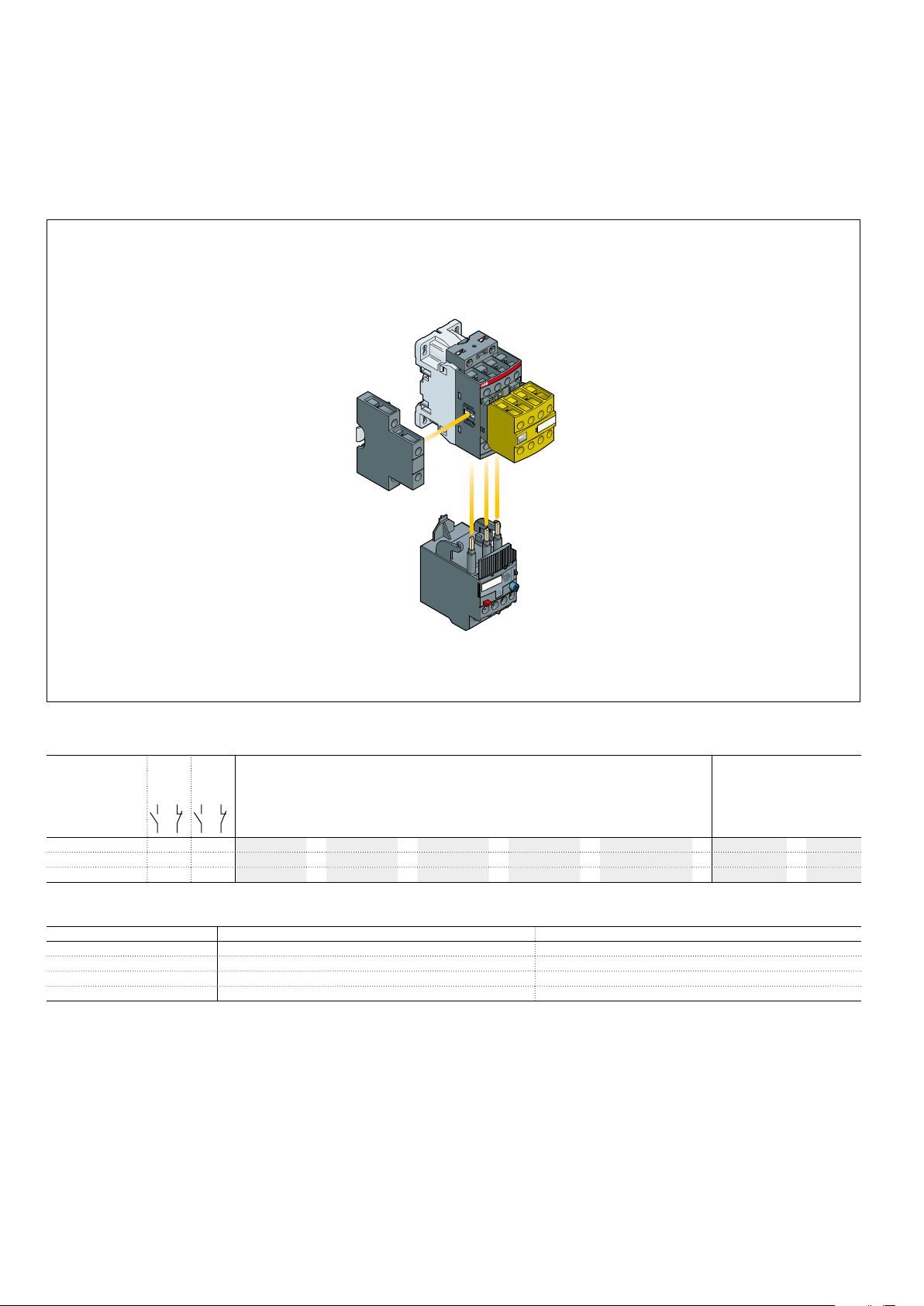
AFS09 ... AFS96 3-pole contactors for safety applications
Main accessories
Contactor and main accessories (other accessories available)
AFS09 ... AFS96-30-22
AFS
contactor
CAL4-11
2-pole auxiliary
contact block
TF42
EF
Overload relay
Main accessory fitting details
Many configurations of accessories are possible depending on whether these are front-mounted or side-mounted.
Main
Contactor
types
AFS09 ... AFS96 3 0 2 2 – – – – 1
AFS09Z ... AFS38Z 3 0 2 2 – – – – – – –
AFS40 ... AFS96 3 0 2 2 – – – – 1
poles
Built-in
Front-mounted accessories Side-mounted accessories
auxiliary
Auxiliary contact blocks Electronic
contacts
1-pole CA4
1-pole CC4 2-pole CAT4-11 4-pole CA4 TEF4 VM 2-pole CAL4-11
timer
Mechanical
interlock unit
(between 2 contactors)
Auxiliary contact blocks
Left side Right side
+
1 –
+
1
+
Overload relays fitting details (1)
Contactor types
AFS09 ... AFS38 TF42 (0.10...38 A) EF19 (0.10...19 A)
AFS26 ... AFS38 TF42 (0.10...38 A) EF45 (9...45 A)
AFS40 ... AFS65 TF65 (22...67 A) EF65 (20...70 A)
AFS80, AFS96 TF96 (40...96 A) EF96 (36...100 A)
The addition of an overload relay on the contactor does not prevent fitting of many other accessories as shown above.
(1) Direct mounting - No kit required.
Thermal overload relays Electronic overload relays
1
8 | ABB
1SBC100313S0201
Page 9
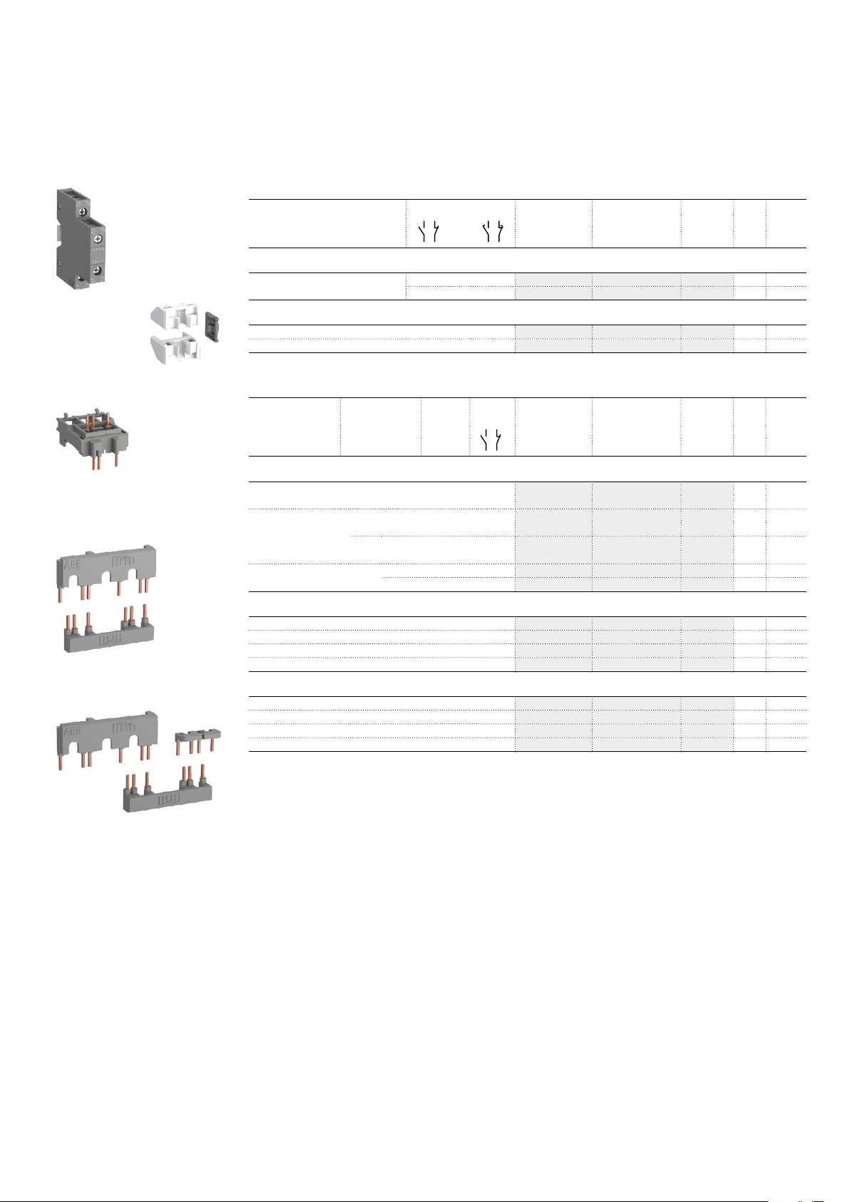
AFS09 ... AFS96 3-pole contactors for safety applications
Main accessories
Ordering Details (1)
For contactors Auxiliary contacts Type Order code Pkg
qty
Weight
(1 pce)
kg
CAL4-11
BEA16-4
BER16-4
1SBC100007V0014
VM4
1SBC100014V0014
1SBC100016V0014
Side-mounted instantaneous auxiliary contact blocks
AFS09 ... AFS96 1 1 – – CAL4-11 1SBN010120R1011 1 0.040
1 1 – – CAL4-11-T 1SBN010120T1011 10 0.040
Mechanical interlock unit
AFS09 ... AFS38 VM4 1SBN030105T1000 10 0.005
1SBC100010V0014
AFS40 ... AFS96 VM96-4 1SBN033405T1000 10 0.006
Note: VM4 and VM96-4 include 2 fixing clips (BB4) to maintain together both contactors.
For contactors Time delay
range
selected by
switch
Delay
type
Auxiliary
contacts
Type Order code Pkg
qty
Connecting links with manual motor starters
AFS09 ... AFS16 with MS116-0.16 … MS116-25, BEA16-4 1SBN081306T1000 10 0.025
MS132-0.16 … MS132-25
AFS26 ... AFS38 with MS116-0.16 … MS116-16, BEA26-4 1SBN082306T1000 10 0.025
MS132-0.16 ... MS132-10
with MS116-20 … MS116-32, BEA38-4 1SBN082306T2000 10 0.030
MS132-12 ... MS132-32
AFS40 ... AFS65 with MS165-16 … MS165-65 BEA65-4 1SBN083406R1000 1 0.090
MS165-16 … MS165-65 (2) BPR65-4 1SBN113405R1000 1 0.014
Connection sets for reversing contactors
AFS09 ... AFS16 BER16-4 1SBN081311R1000 1 0.045
AFS26 ... AFS38 BER38-4 1SBN082311R1000 1 0.100
AFS40 ... AFS65 BER65-4 1SBN083411R1000 1 0.175
AFS80 ... AFS96 BER96-4 1SBN083911R1000 1 0.250
Connection sets for star-delta starting
AFS09 ... AFS16 with or without VM4 BEY16-4 1SBN081313R2000 1 0.050
AFS26 ... AFS38 with or without VM4 BEY38-4 1SBN082713R2000 1 0.110
AFS40 ... AFS65 with or without VM96-4 BEY65-4 1SBN083413R2000 1 0.200
AFS80 ... AFS96 with or without VM96-4 BEY96-4 1SBN083913R2000 1 0.250
(1) For more information, refer to "Accessories" section.
(2) Use one BPR65-4 for each contactor AF540 ... AF565.
1SBC100018V0014
Weight
(1 pce)
kg
BEY16-4
1SBC100314S0201 - Rev. A
ABB | 9
Page 10
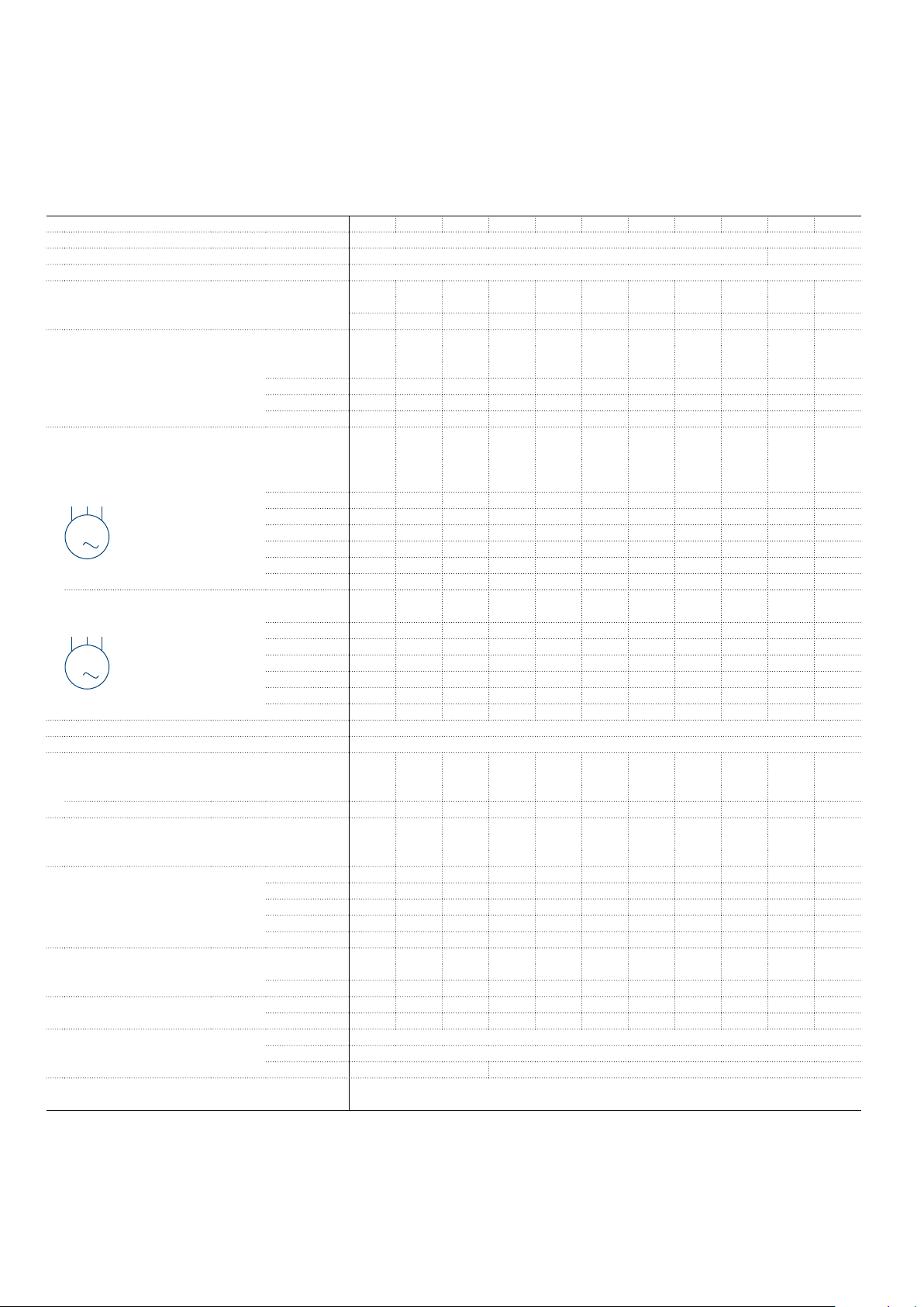
AFS09 ... AFS96 3-pole contactors for safety application
Technical data
Main pole - Utilization characteristics according to IEC
Contactor types
Standards IEC 60947-1 / 60947-4-1 and EN 60947-1 / 60947-4-1
Rated operational voltage Ue max. 690 V 1000 V
Rated frequency (without derating) 50 / 60 Hz
Conventional free-air thermal current Ith
acc. to IEC 60947-4-1, open contactors, θ ≤ 40 °C
With conductor cross-sectional area 6 mm² 6 mm² 6 mm² 10 mm² 10 mm² 10 mm² 35 mm² 35 mm² 35 mm² 50 mm² 50 mm²
AC-1 Utilization category
For air temperature close to contactor
Ie / Rated operational current AC-1
Ue max. ≤ 690 V, 50/60 Hz
With conductor cross-sectional area 4 mm² 6 mm² 6 mm² 10 mm² 10 mm² 10 mm² 25 mm² 35 mm² 35 mm² 50 mm² 50 mm²
AC-3 Utilization category
For air temperature close to contactor θ ≤ 60 °C
Ie / Max. rated operational current AC-3 (1)
M
3-phase motors
3
Rated operational power AC-3 (1)
M
3
Rated making capacity AC-3 10 x Ie AC-3 acc. to IEC 60947-4-1
Rated breaking capacity AC-3 8 x Ie AC-3 acc. to IEC 60947-4-1
AC-8a Utilization category
(without thermal overload relay - Ue 400 V 50/60 Hz - θ ≤ 40 °C)
Ie / Rated operational current AC-8a 12 A 16 A 22 A 30 A 40 A 50 A 53 A 70 A 85 A 105 A 120 A
Rated operational power AC-8a 5.5 kW 7.5 kW 11 kW 15 kW 20 kW 25 kW 25 kW 37 kW 45 kW 55 kW 65 kW
Short-circuit protection device for contactors
without thermal overload relay - Motor protection excluded (2)
Ue ≤ 500 V AC - gG type fuse 25 A 32 A 32 A 50 A 63 A 63 A 80 A 110 A 125 A 160 A 160 A
Rated short-time withstand current Icw
at 40 °C ambient temperature,
in free air from a cold state
Maximum breaking capacity
cos φ = 0.45
Power dissipation per pole
Max. electrical switching frequency
B10d
Calculated for 50% of the rated current value Ie at AC-3 / 400V 1.3 million operating cycles
(1) For the corresponding kW/A or hp/A values of 1500 r.p.m, 50 Hz or 1800 r.p.m, 60 Hz, 3-phase motors, see "Motor rated operational powers and currents".
(2) For the protection of motor starters against short circuits, see "Coordination with short-circuit protection devices".
1500 r.p.m. 50 Hz
1800 r.p.m. 60 Hz
3-phase motors
AC / DC operated
θ ≤ 40 °C
θ ≤ 60 °C
θ ≤ 70 °C
220-230-240 V
380-400 V
415 V
440 V
500 V
690 V
1000 V
220-230-240 V
380-400 V
415 V
440 V
500 V
690 V
1000 V
1 s
10 s
30 s
1 min
15 min
at 440 V
at 690 V
Ie / AC-1
Ie / AC-3
AC-1
AC-3
AC-2, AC-4
AFS09 AFS12 AFS16 AFS26 AFS30 AFS38 AFS40 AFS52 AFS65 AFS80 AFS96
35 A 35 A 35 A 50 A 50 A 50 A 105 A 105 A 105 A 130 A 130 A
25 A 28 A 30 A 45 A 50 A 50 A 70 A 100 A 105 A 125 A 130 A
25 A 28 A 30 A 40 A 42 A 42 A 60 A 80 A 90 A 100 A 105 A
22 A 24 A 26 A 32 A 37 A 37 A 50 A 70 A 80 A 85 A 90 A
9 A 12 A 18 A 26 A 33 A 40 A 40 A 53 A 65 A 80 A 96 A
9 A 12 A 18 A 26 A 32 A 38 A 40 A 53 A 65 A 80 A 96 A
9 A 12 A 18 A 26 A 32 A 38 A 40 A 53 A 65 A 80 A 96 A
9 A 12 A 18 A 26 A 32 A 38 A 40 A 53 A 65 A 80 A 96 A
9.5 A 12.5 A 15 A 23 A 28 A 33 A 35 A 45 A 55 A 65 A 80 A
7 A 9 A 10.5 A 17 A 21 A 24 A 25 A 35 A 39 A 49 A 57 A
25 A 30 A
2.2 kW 3 kW 4 kW 6.5 kW 9 kW 11 kW 11 kW 15 kW 18.5 kW 22 kW 25 kW
4 kW 5.5 kW 7.5 kW 11 kW 15 kW 18.5 kW 18.5 kW 22 kW 30 kW 37 kW 45 kW
4 kW 5.5 kW 9 kW 11 kW 15 kW 18.5 kW 22 kW 30 kW 37 kW 45 kW 55 kW
4 kW 5.5 kW 9 kW 15 kW 18.5 kW 22 kW 22 kW 30 kW 37 kW 45 kW 55 kW
5.5 kW 7.5 kW 9 kW 15 kW 18.5 kW 22 kW 22 kW 30 kW 37 kW 45 kW 55 kW
5.5 kW 7.5 kW 9 kW 15 kW 18.5 kW 22 kW 22 kW 30 kW 37 kW 45 kW 55 kW
35 kW 40 kW
300 A 300 A 300 A 700 A 700 A 700 A 1000 A 1000 A 1000 A 1200 A 1200 A
150 A 150 A 150 A 350 A 350 A 350 A 600 A 600 A 600 A 780 A 780 A
80 A 80 A 80 A 225 A 225 A 225 A 350 A 350 A 350 A 450 A 450 A
60 A 60 A 60 A 150 A 150 A 150 A 250 A 250 A 250 A 300 A 300 A
35 A 35 A 35 A 50 A 50 A 50 A 110 A 110 A 110 A 140 A 140 A
250 A 250 A 250 A 500 A 500 A 500 A 950 A 950 A 950 A 1150 A 1150 A
106 A 106 A 106 A 200 A 200 A 200 A 600 A 600 A 600 A 750 A 750 A
0.8 W 1 W 1.2 W 1.8 W 2.4 W 2.4 W 3 W 6.3 W 7 W 7.6 W 8.2 W
0.1 W 0.2 W 0.35 W 0.6 W 0.9 W 1.3 W 1 W 1.7 W 2.7 W 3 W 4.5 W
600 cycles/h
1200 cycles/h
300 cycles/h 150 cycles/h
10 | ABB
1SBC100307S0201 - Rev. A
Page 11
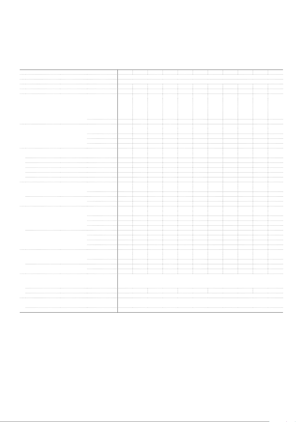
AFS09 ... AFS96 3-pole contactors for safety application
Technical data
Main pole - Utilization characteristics according to UL / NEMA / CSA
Contactor types
Standards UL 60947-4-1, CSA-C22.2 No. 60947-4-1
Maximum operational voltage 600 V
NEMA size
NEMA continuous amp rating
NEMA maximum horse power ratings
1-phase, 60Hz
NEMA maximum horse power ratings
3-phase, 60Hz
UL / CSA general use rating
600V AC
With conductor cross-sectional area
1 pole
2 poles in serie
3 poles in serie
With conductor cross-sectional area
UL / CSA maximum 1-phase motor rating
Full load current
Horse power rating
UL / CSA maximum 3-phase motor rating
Full load current (1)
Horse power rating (1)
UL / CSA - DC motor starting - 3 poles in series
Full Load Amps
Horse power rating
Short-circuit protection device for contactors
without thermal overload relay - Motor protection excluded
High fault current 100 kA
Fuse rating 30 A 60 A 100 A 150 A 200 A
Fuse type, 600V J
Maximum electrical switching frequency
For general use 600 cycles/h
For motor use 1200 cycles/h
(1) For the corresponding kW/A or hp/A values of 1500 r.p.m, 50 Hz or 1800 r.p.m, 60 Hz, 3-phase motors, see "Motor rated operational powers and currents".
AC / DC operated
Thermal current
115V AC
230V AC
200V AC
230V AC
460V AC
575V AC
80 V DC
160 V DC
240 V DC
120V AC
240V AC
120V AC
240V AC
200-208V AC
220-240V AC
440-480V AC
550-600V AC
200-208V AC
220-240V AC
440-480V AC
550-600V AC
125 V DC
250 V DC
125 V DC
250 V DC
AFS09 AFS12 AFS16 AFS26 AFS30 AFS38 AFS40 AFS52 AFS65 AFS80 AFS96
00 0 - 1 - - 2 - - 3 9 A 18 A - 27 A - - 45 A - - 90 A -
1/3 hp 1 hp - 2 hp - - 3 hp - - - -
1 hp 2 hp - 3 hp - - 7.5 hp - - - -
1-1/2 hp 3 hp - 7-1/2 hp - - 10 hp - - 25 hp 1-1/2 hp 3 hp - 7-1/2 hp - - 15 hp - - 30 hp 2 hp 5 hp - 10 hp - - 25 hp - - 50 hp 2 hp 5 hp - 10 hp - - 25 hp - - 50 hp -
25 A 28 A 30 A 45 A 50 A 50 A 60 A 80 A 90 A 105 A 115 A
AWG 10 AWG 10 AWG 10 AWG 8 AWG 8 AWG 8 AWG 6 AWG 4 AWG 2
25 A 28 A 30 A 45 A 50 A 50 A 60 A 80 A 90 A 105 A 115 A
25 A 28 A 30 A 45 A 50 A 50 A 60 A 80 A 90 A 105 A 115 A
25 A 28 A 30 A 45 A 50 A 50 A 60 A 80 A 90 A 105 A 115 A
AWG 10 AWG 10 AWG 10 AWG 8 AWG 8 AWG 8
13.8 A 16 A 20 A 24 A 24 A 24 A 34 A 34 A 56 A 80 A 80 A
10 A 12 A 17 A 17 A 28 A 28 A 40 A 50 A 68 A 68 A 88 A
3/4 hp 1 hp 1-1/2 hp 2 hp 2 hp 2 hp 3 hp 3 hp 5 hp 7-1/2 hp 7-1/2 hp
1-1/2 hp 2 hp 3 hp 3 hp 5 hp 5 hp 7-1/2 hp 10 hp 15 hp 15 hp 20 hp
7.8 A 11 A 17.5 A 25.3 A 32.2 A 32.2 A 32.2 A 48.3 A 62.1 A 78.2 A 92 A
6.8 A 9.6 A 15.2 A 22 A 28 A 28 A 42 A 54 A 68 A 80 A 80 A
7.6 A 11 A 14 A 21 A 27 A 34 A 40 A 52 A 65 A 77 A 77 A
9 A 11 A 17 A 22 A 27 A 32 A 41 A 52 A 62 A 77 A 77 A
2 hp 3 hp 5 hp 7-1/2 hp 10 hp 10 hp 10 hp 15 hp 20 hp 25 hp 30 hp
2 hp 3 hp 5 hp 7-1/2 hp 10 hp 10 hp 15 hp 20 hp 25 hp 30 hp 30 hp
5 hp 7-1/2 hp 10 hp 15 hp 20 hp 25 hp 30 hp 40 hp 50 hp 60 hp 60 hp
7-1/2 hp 10 hp 15 hp 20 hp 25 hp 30 hp 40 hp 50 hp 60 hp 75 hp 75 hp
9.5 A 13.2 A 17 A 25 A 25 A 25 A 40 A 58 A 76 A 76 A 110 A
8.5 A 12.2 A 12.2 A 20 A 29 A 29 A 38 A 55 A 72 A 89 A 106 A
1 hp 1-1/2 hp 2 hp 3 hp 3 hp 3 hp 5 hp 7-1/2 hp 10 hp 10 hp 15 hp
2 hp 3 hp 3 hp 5 hp 7-1/2 hp 7-1/2 hp 10 hp 15 hp 20 hp 25 hp 30 hp
ABB | 11
1SBC100309S0201
1SBC100309S0201
Page 12
AFS09 ... AFS96 3-pole contactors for safety application
B2
A
C2
C1
Pos
Technical data
General technical data
Contactor types
Rated insulation voltage Ui
acc. to IEC 60947-4-1 690 V 1000 V
acc. to UL / CSA 600 V
Rated impulse withstand voltage Uimp. 6 kV 8 kV
Electromagnetic compatibility Devices complying with IEC 60947-1 / EN 60947-1 - Environments A and B
Ambient air temperature close to contactor
Operation Fitted with thermal overload relay -25 ... +60 °C
Without thermal overload relay -40 ... +70 °C
Storage -60 ... +80 °C
Climatic withstand Category B according to IEC 60947-1 Annex Q
Maximum operating altitude (without derating) 3000 m
Mechanical durability
Number of operating cycles 10 million operating cycles
Maximum switching frequency 3600 cycles/h
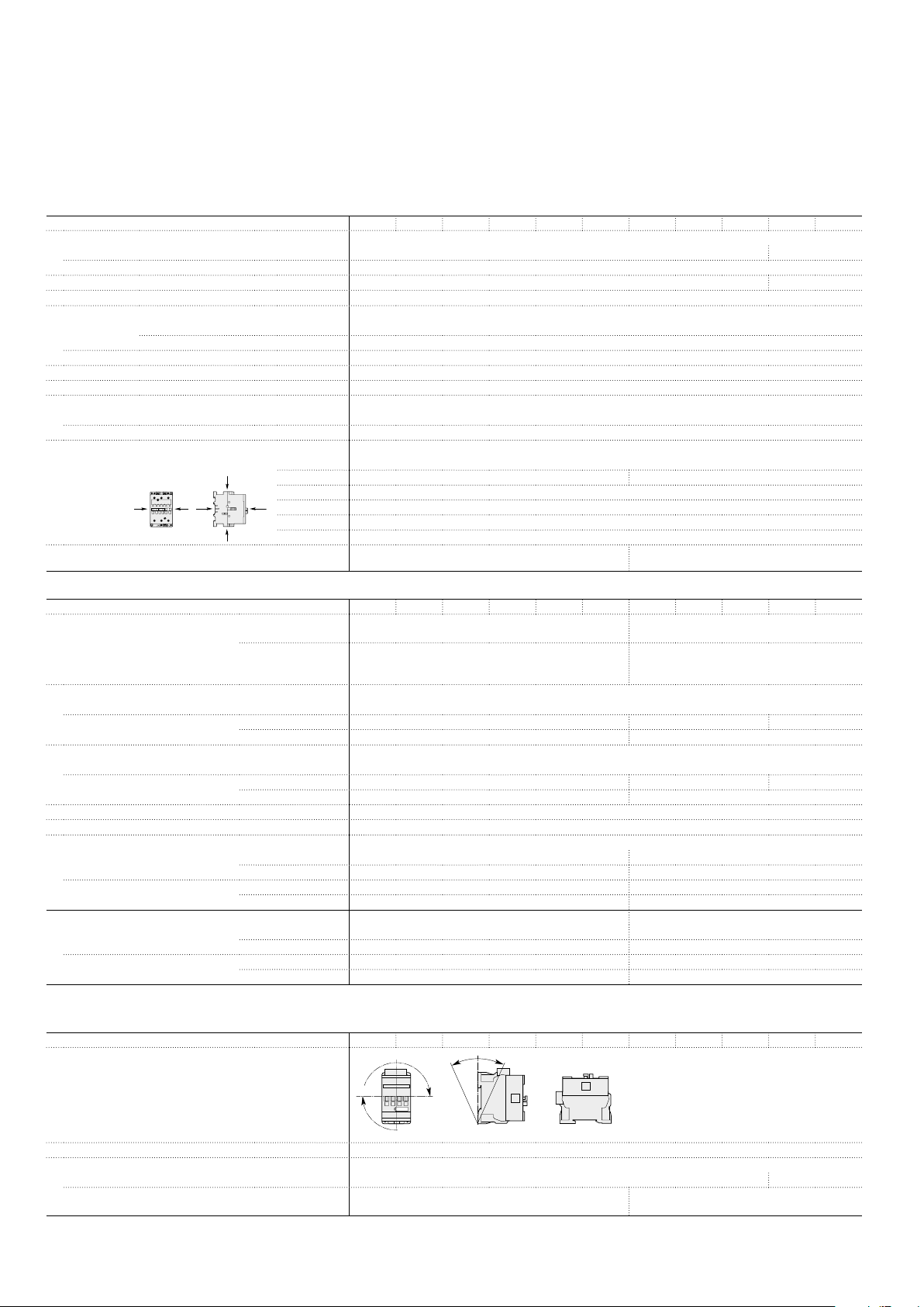
Shock withstand
acc. to IEC 60068-2-27 and EN 60068-2-27
Mounting position 1
B1
A
Vibration withstand
acc. to IEC 60068-2-6
AC / DC operated
Shock direction
A
B1
B2
C1
C2
AFS09 AFS12 AFS16 AFS26 AFS30 AFS38 AFS40 AFS52 AFS65 AFS80 AFS96
1/2 sinusoidal shock for 11 ms: no change in contact position, closed or open position
30 g 25 g
25 g closed position / 5 g open position
15 g
25 g
25 g
5 ... 300 Hz
4 g Closed position / 2 g Open position
5 ... 300 Hz
3 g Closed position / 3 g Open position
Magnet system characteristics
Contactor types
Coil operating limits
acc. to IEC 60947-4-1
AC control voltage 50/60 Hz
Rated control circuit voltage Uc 24 ... 250 V AC
Coil consumption
DC control voltage
Rated control circuit voltage Uc 20 ... 250 V DC
Coil consumption
PLC-output control (AFS..Z coil 30) ≥ 250 mA 24 V DC for PLCs and safety PLCs using broken wire detection
Drop-out voltage ≤ 60 % Uc min.
Operating time
Between coil energization and:
Between coil de-energization and:
Operating time AFS..Z coil 30 - 24 V DC
Between coil energization and:
Between coil de-energization and:
(1) AFS09 ... ASF38 ≤ 35 ms for 20 °C ≤ θ ≤ 70 °C
AC / DC operated
AC supply
DC supply
Average pull-in value
Average holding value
Average pull-in value
Average holding value
N.O. contact closing
N.C. contact opening
N.O. contact opening
N.C. contact closing
N.O. contact closing
N.C. contact opening
N.O. contact opening
N.C. contact closing
AFS09 AFS12 AFS16 AFS26 AFS30 AFS38 AFS40 AFS52 AFS65 AFS80 AFS96
At θ ≤ 60 °C 0.85 x Uc min...1.1 x Uc max.
At θ ≤ 70 °C 0.85 x Uc min ... 1.1 x Uc max.
At θ ≤ 70 °C 0.85 x Uc min...Uc max.
at θ ≤ 60 °C 0.85 x Uc min ... 1.1 x Uc max
at θ ≤ 70 °C 0.85 x Uc min ... 1.1 x Uc max
at θ ≤ 70 °C (AFS) 0.85 x Uc min ... Uc max
(AFS..Z coil 30) Uc
50 VA 25 VA 40 VA
2.2 VA / 2 W 4 VA / 2 W
(AFS) 50 W - (AFS..Z coil 30) 6 W 25 W 40 W
(AFS) 2 W - (AFS..Z coil 30) 1.7 W 2 W
40 ... 95 ms 42 ... 100 ms
38 ... 90 ms 38 ... 95 ms
11 ... 95 ms (1) 17 ... 100 ms
13 ... 98 ms 19 ... 105 ms
27 … 53 ms –
20 … 35 ms –
17 … 29 ms –
22 … 57 ms –
Mounting characteristics and conditions for use
Contactor types
Mounting positions
Mounting distances
Fixing
12 | ABB
On rail according to IEC 60715, EN 60715 35 x 7.5 mm or 35 x 15 mm 35 x 15 mm
By screws (not supplied) 2 x M4 screws placed diagonally 2 x M4 or 2 x M6 screws
AC / DC operated
AFS09 AFS12 AFS16 AFS26 AFS30 AFS38 AFS40 AFS52 AFS65 AFS80 AFS96
. 2
Pos. 4
Pos. 1 Pos. 1 ± 30°
+30° -30°
Pos. 3
Pos. 5
The contactors can be assembled side by side
placed diagonally
1SBC100310S0201
Page 13
L
6
L
6
AFS09 ... AFS96 3-pole contactors for safety application
Technical data
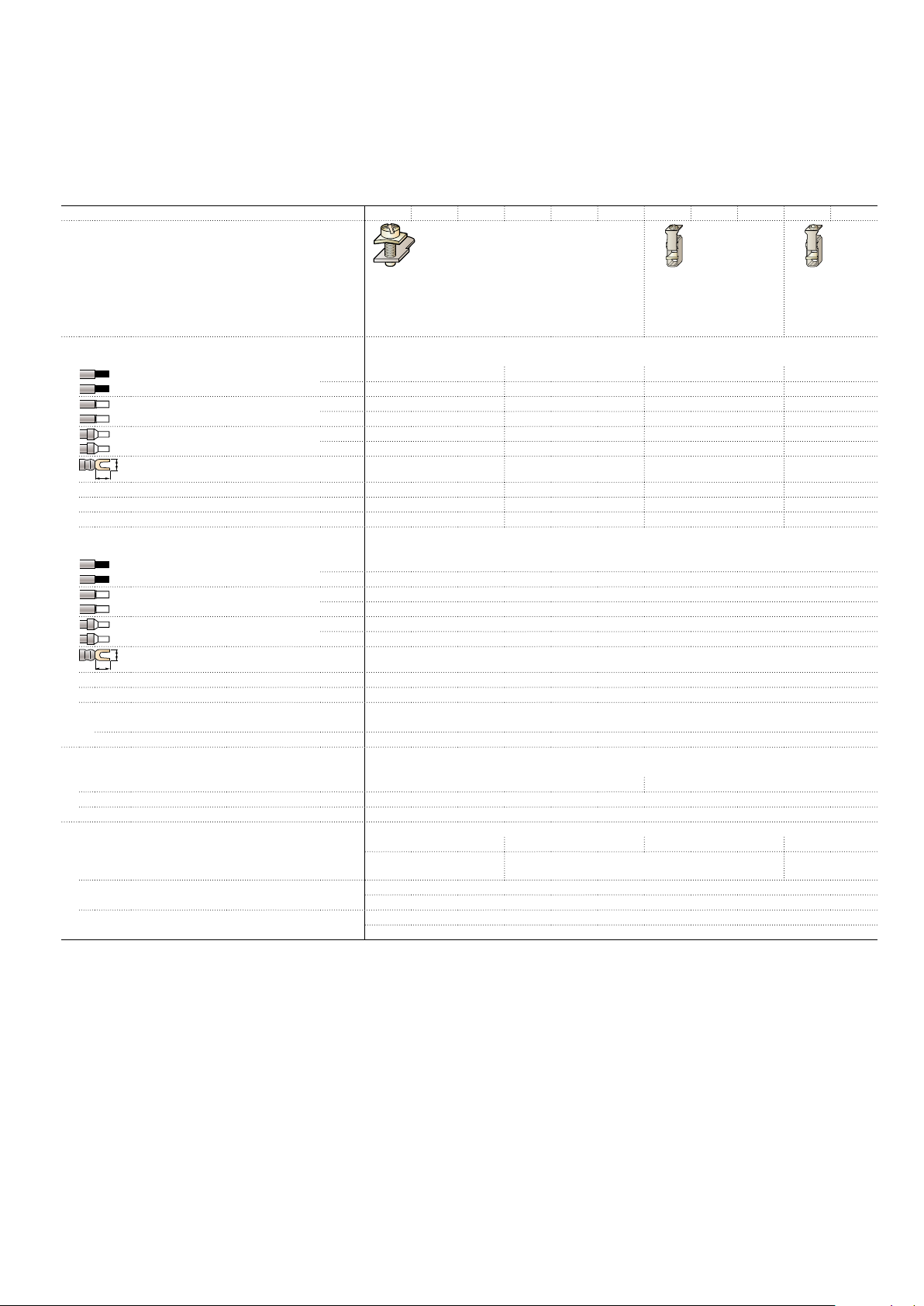
Connecting characteristics
Contactor types
Main terminals
Connection capacity (min. ... max.)
Main conductors (poles)
Rigid Solid (≤ 4 mm²)
Flexible with non
insulated ferrule
Flexible with insulated ferrule
Bars or lugs
Connection capacity acc. to UL/CSA
Stripping length 10 mm 14 mm 16 mm 17 mm
Tightening torque recommended 1.5 Nm / 13 lb.in 2.5 Nm / 22 lb.in 4 Nm / 35 lb.in 6 Nm / 53 lb.in
Auxiliary conductors
(built-in auxiliary terminals + coil terminals)
Rigid solid
Flexible with non
insulated ferrule
Flexible with insulated ferrule
Bars or lugs
Connection capacity acc. to UL/CSA
Stripping length 10 mm
Tightening torque
Coil terminals recommended 1.2 Nm / 11 lb.in
Built-in auxiliary terminals recommended 1.2 Nm / 11 lb.in
Degree of protection
acc. to IEC 60947-1 / EN 60947-1 and IEC 60529 / EN 60529
Main terminals IP20 IP10
Coil terminals IP20
Built-in auxiliary terminals IP20
Screw terminals Delivered in open position, screws of unused terminals must be tightened
Main terminals M3.5 M4 M6 M8
Coil terminals M3.5
Built-in auxiliary terminals M3.5
AC / DC operated
1 x
2 x
1 x
2 x
1 x
2 x
L <
1 or 2 x
1 x
2 x
1 x
2 x
1 x
2 x
L <
1 or 2 x
Screwdriver type
Screwdriver type
Screwdriver type
AFS09 AFS12 AFS16 AFS26 AFS30 AFS38 AFS40 AFS52 AFS65 AFS80 AFS96
Screw terminals with cable clamp Screw terminals with
double connector
2 x (9.3 width x 7.9/10.3
depth)
Screw terminals
with double connector
2 x (12.4 width x
9.3/11.1 depth)
1 ... 6 mm² 2.5 ... 10 mm² 6 ... 35 mm² 6 ... 70 mm²
1 ... 6 mm² 2.5 ... 10 mm² 6 ... 35 mm² 6 ... 50 mm²
0.75 ... 6 mm² 1.5 ... 10 mm² 4 ... 35 mm² 6 ... 50 mm²
0.75 ... 6 mm² 1.5 ... 10 mm² 4 ... 35 mm² 6 ... 50 mm²
0.75 ... 4 mm² 1.5 ... 10 mm² 4 ... 35 mm² 6 ... 50 mm²
0.75 ... 2.5 mm² 1.5 ... 4 mm² 4 ... 35 mm² 6 ... 50 mm²
9.6 mm 12.5 mm 9.2 mm 12.2 mm
AWG 16 ... 10 AWG 14 ... 8 AWG 10 ... 2 AWG 6 ... 1
1 ... 2.5 mm²
1 ... 2.5 mm²
0.75 ... 2.5 mm²
0.75 ... 2.5 mm²
0.75 ... 2.5 mm²
0.75 ... 1.5 mm²
8 mm
AWG 18 ... 14
Flat Ø 5.5 / Pozidriv 2 Flat Ø 6.5 / Pozidriv 2 hexagon socket
(s = 4 mm)
Flat Ø 5.5 / Pozidriv 2
Flat Ø 5.5 / Pozidriv 2
1SBC100311S0201
ABB | 13
Page 14
AFS09 ... AFS96 3-pole contactors for safety applications
Technical data
Built-in auxiliary contacts according to IEC
Contactor types
Rated operational voltage Ue max.
Rated frequency (without derating)
Conventional free air thermal current Ith - θ ≤ 40°C
Ie / Rated operational current AC-15
acc. to IEC 60947-5-1
Making capacity AC-15
Breaking capacity AC-15
Ie / Rated operational current DC-13
acc. to IEC 60947-5-1
Short-circuit protection device gG type fuse
Rated short-time withstand current Icw
Minimum switching capacity
with failure rate acc. to IEC 60947-5-4 10
Non-overlapping time between N.O. and N.C. contacts
Power dissipation per pole at 6A
Maximum electrical switching frequency
Mechanically linked contacts
acc. to annex L of IEC 60947-5-1
Mirror contacts
acc. to annex F of IEC 60947-4-1
AC / DC operated
24-127V 50/60Hz
220-240V 50/60Hz
400-440V 50/60Hz
500V 50/60Hz
690V 50/60Hz
24V DC
48V DC
72V DC
110V DC
125V DC
220V DC
250V DC
400 V DC
500 V DC
600 V DC
for 1.0s
for 0.1s
AC-15
DC-13
AFS09 AFS12 AFS16 AFS26 AFS30 AFS38 AFS40 AFS52 AFS65 AFS80 AFS96
690 V
50 / 60 Hz
16 A
6 A
4 A
3 A
2 A
2 A
10 x Ie AC-15 acc. to IEC 60947-5-1
10 x Ie AC-15 acc. to IEC 60947-5-1
6 A / 144 W
2.8 A / 134 W
1 A / 72 W
0.55 A / 60 W
0.55 A / 69 W
0.27 A / 60 W
0.27 A / 68 W
0.15 A / 60 W
0.13 A / 65 W
0.1 A / 60 W
10 A
100 A
140 A
12 V / 3 mA
≥ 2 ms
0.1 w
1200 cycles/h
900 cycles/h
Built-in N.O. or N.C. auxiliary contacts and additional N.O. or N.C. auxiliary contacts (CAL4 aux. contact
blocks) are mechanically linked contacts.
Built-in N.C. auxiliary contacts or additional N.C. auxiliary contacts (CAL4 aux. contact blocks) are mirror
contacts.
-7
Built-in auxiliary contacts according to UL / CSA
Contactor types
Maximum operational voltage
Pilot duty
AC thermal rated current 10 A
AC maximum volt-ampere making 7200 VA
AC maximum volt-ampere breaking 720 VA
DC thermal rated current 2.5 A
DC maximum volt-ampere making-breaking 69 VA
14 | ABB
DC operated AFS09 AFS12 AFS16 AFS26 AFS30 AFS38 AFS40 AFS52 AFS65 AFS80 AFS96
600 _VACPDC, 600 _VDCPDC
A600, Q600
1SBC100312S0201
Page 15
21
22
5L33L2
A1
A2
6T34T2
1L1
2T1
13
14
43
44
31
32
AFS09 ... AFS96 3-pole contactors for safety applications
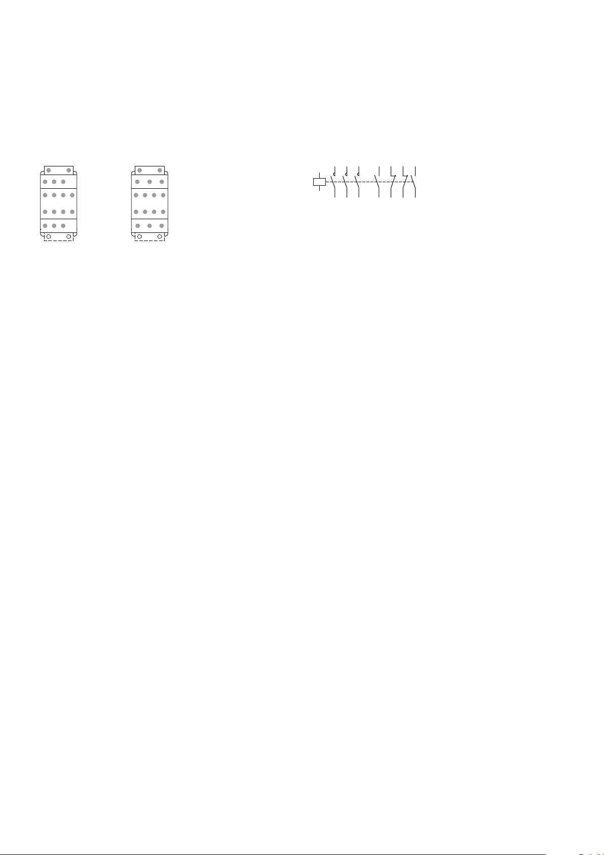
Terminal marking and positioning
AFS09 ... AFS96 contactors - AC / DC operated
Standard devices
A1 A2
5L3
3L2
1L1
43
NO31NC21NC13NO
44322214
6T3
4T2
2T1
A1 A2
AFS09 ... AFS16..-30-22
A1 A2
5L3
3L2
1L1
43
NO31NC21NC13NO
44322214
6T3
4T2
2T1
A1 A2
AFS26 ... AFS96..-30-22
NO
NO
AFS09 ... AFS96..-30-22
NC
NO
NC
NO
NC
NC
1SBC 100315S 0201
ABB | 15
Page 16

3-pole contactors
Electrical durability and utilization categories
General
Utilization categories determine the current making and breaking conditions relating to the characteristics of the loads to be
controlled by the contactors. International standard IEC 60947-4-1 and European standard EN 60947-4-1 are the standards to
be referred to.
If Ic is the current to be broken by the contactor and Ie the rated operational current normally drawn by the load, then:
– Categories AC-1 and AC-3: Ic = Ie
– Category AC-2: Ic = 2.5 x Ie
– Category AC-4: Ic = 6 x Ie
Generally speaking Ic = m x Ie where m is a multiple of the load operational current.
On next pages, the curves corresponding to categories AC-1, AC-3 and AC-4 represent the electrical durability variation of
standard contactors in relation to the breaking current Ic.
Electrical durability is expressed in millions of operating cycles.
Curve utilization mode
Electrical durability forecast and contactor selection for categories AC-1, AC-2, AC-3 or AC-4
• Note the characteristics of the load to be controlled:
– Operational voltage .......................................... Ue
– Current normally drawn .................................... Ie
– Utilization category .......................................... AC-1, AC-2, AC-3 or AC-4
– Breaking current .............................................. Ic = Ie for AC-1 and for AC-3 ; Ic = 2.5 x Ie for AC-2 ; Ic = 6 x Ie for AC-4
• Define the number of operating cycles N required.
• On the diagram corresponding to the operational category, select the contactor with the curve immediately above the inter-
section point (Ic ; N).
(Ue / Ie / kW relation for motors, see "Motor rated operational powers and currents").
Electrical durability forecast and contactor selection for mixed duty motor control: AC-3 (Ic = Ie) type switching off while
"motor running" and, occasionally, AC-4 (Ic = 6 x Ie) type switching off while "motor accelerating"
• Note the characteristics of the motor to be controlled:
– Operational voltage ...................................................... Ue
– Current normally drawn while "motor running" ............... Ie
– Breaking current for AC-3 ............................................ Ic = Ie
– Breaking current for AC-4 while "motor accelerating" ..... Ic = 6 x Ie
– Percentage of AC-4 operating cycles ............................ K (on the basis of the total number of operating cycles)
• Define the total number of operating cycles N required.
• Note the smallest contactor rating compatible for AC-3 (Ue / Ie) on Main pole utilization characteristic table
• For the selected contactor make a note of the following in relation to the voltage using diagram AC-3 in next pages:
– The number of operating cycles A for Ic = Ie (AC-3)
– The number of operating cycles B for Ic = 6 x Ie (AC-4)
• Calculate the estimated number of cycles N’ (N’ is always below A)
A
N'=
1 + 0.01 K (A/B - 1)
• If N' is too low in relation to the target N, calculate the estimated number of cycles for a higher contactor rating.
Case of uninterrupted duty
For uninterrupted duty, some verifications of preventing maintenance are necessary to check the functionality of the concerned
product (consult us).
The combined effect of environmental conditions and the proper temperature of the product may require some disposals. As a
matter of fact, for this duty, the use duration prevails over the number of operating cycles.
(Ue / Ie / kW relation for motors, see "Motor rated operational powers and currents")
(see “Technical data”).
16 | ABB
1SBC101314S0201
Page 17
3-pole contactors
0.1
0.2
0.3
0.5
1000
26.5
Electrical durability
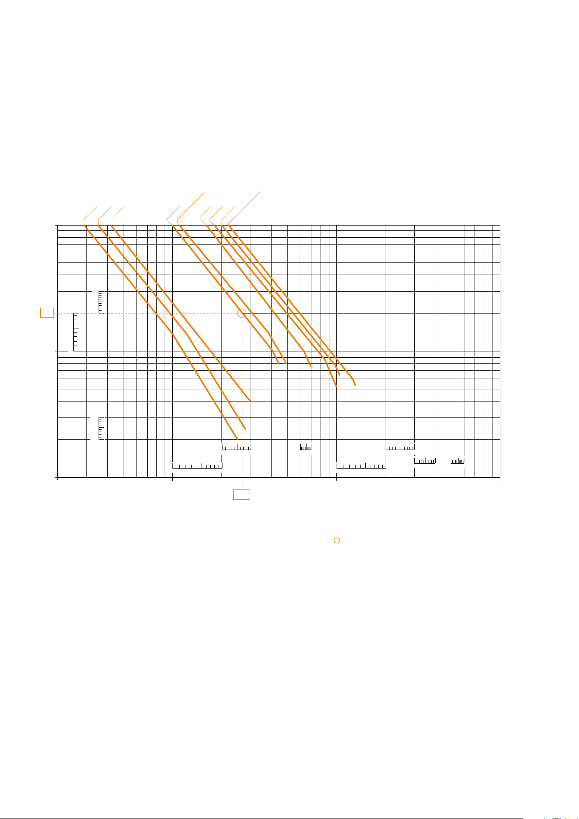
Electrical durability for AC-1 utilization category - Ue ≤ 690 V
Switching non-inductive or slightly inductive loads. The breaking current Ic for AC-1 is equal to the rated operational current of
the load.
Ambient temperature and maximum electrical switching frequency: see "Technical data".
Millions of
operating
cycles
10
5
AFS09
AFS12
AFS16
AFS26
AFS30, AFS38
AFS40
AFS52
AFS65
AFS80, AFS96
3
2
1
23 5203050 200 300 500
9
7
5
3
1
9
7
5
3
1
9
7
5
3
1
13579
13579
13579 159
13579
10 100
Example:
Ic / AC-1 = 26.5 A – Electrical durability required = 2 millions operating cycles.
Using the AC-1 curves above select the AFS26 contactor at intersection "
" (26.5 A / 2 millions operating cycles).
13579 159
Breaking current Ic (A)
1SBC100316S0201
ABB | 17
Page 18
3-pole contactors
1000
Electrical durability
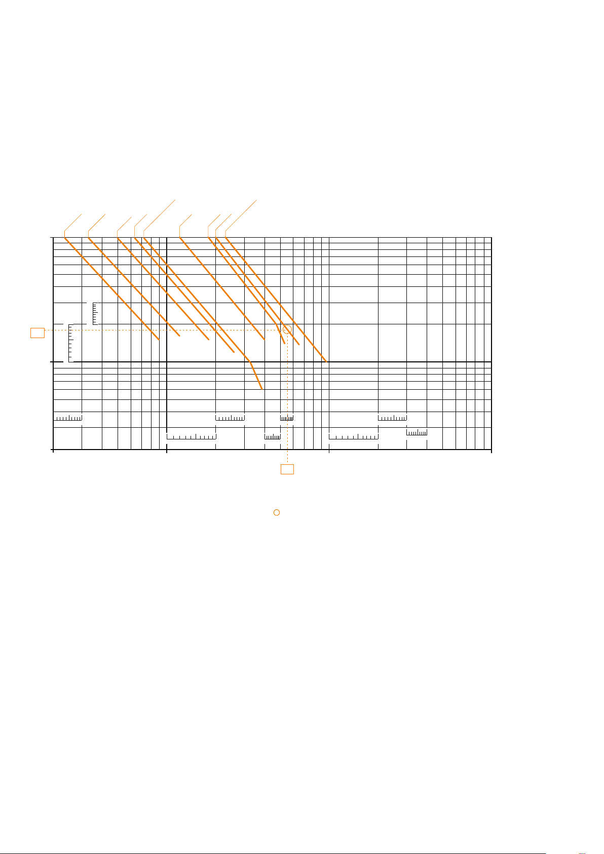
Electrical durability for AC-3 utilization category - Ue ≤ 440 V.
Switching cage motors: starting and switching off running motors. The breaking current Ic for AC-3 is equal to the rated operational current Ie (Ie = motor full load current).
Ambient temperature and maximum electrical switching frequency: see "Technical data".
Millions of
operating
cycles
10
5
AFS09
AFS12
AFS16
AFS26
AFS30, AFS38
AFS40
AFS52
AFS65
AFS80, AFS96
3
2
1.8
1
9
7
5
3
1
9
7
5
3
1
0.5
13579 13579
0.3
13579
159
159
13579
13579
13579
0.2
23 5203050 200 300 500
10 100
55
Breaking current Ic (A)
Example:
Motor power 30 kW for AC-3 - Ue = 400 V and Ie = 55 A utilization – Electrical durability required = 1.8 million operating cycles.
For AC-3: Ic = Ie. Select the AFS65 contactor at intersection " " (55 A / 1.8 million operating cycles) on the curves (AC-3 - Ue ≤ 440 V).
18 | ABB
1SB C100 317S0 201
Page 19
3-pole contactors
1000
0.2
0.3
0.5
Electrical durability
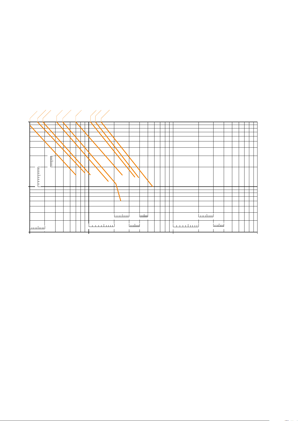
Electrical durability for AC-3 utilization category - 440 V < Ue ≤ 690 V.
Switching cage motors: starting and switching off running motors. The breaking current Ic for AC-3 is equal to the rated operational current Ie (Ie = motor full load current).
Ambient temperature and maximum electrical switching frequency: see "Technical data".
Millions of
operating
cycles
AFS12
10
AFS16
AFS09
5
AFS26
AFS30
AFS38
AFS40
AFS52
AFS65
AFS80
AFS96
3
2
1
13579
23 5203050 200 300 500
9
7
5
3
1
9
7
5
3
1
13579
13579
13579
13579
13579
159
13579
10 100
Breaking current Ic (A)
1SBC 100318S 0201
ABB | 19
Page 20
3-pole contactors
300010001001023 5203050 200 300 500 2000 5000
0.005
Electrical durability
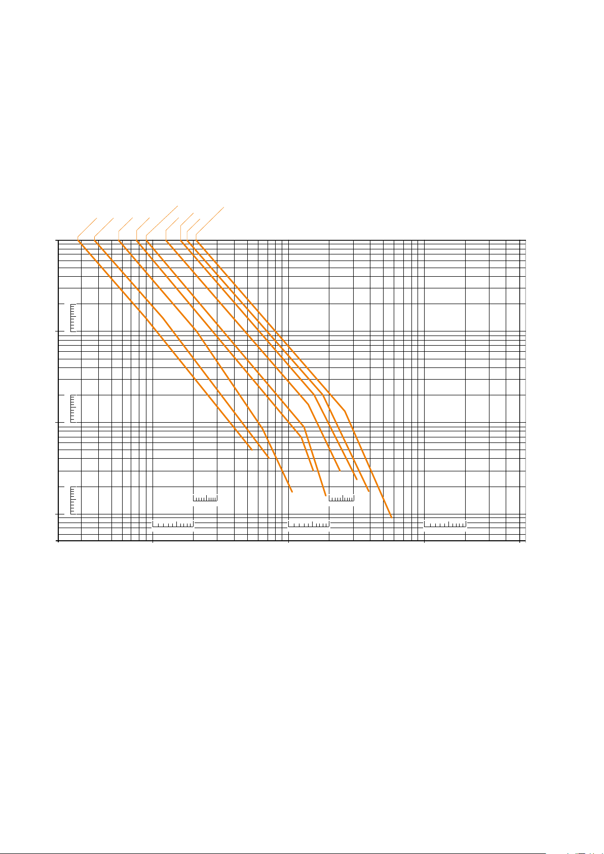
Electrical durability for AC-2 or AC-4 utilization category - Ue ≤ 440 V
Ambient temperature ≤ 60 °C for AFS09 ... AFS96
Switching cage motors: starting, reverse operation and step-by-step operation. The breaking current Ic is equal to 2.5 x Ie for
AC-2 and 6 x Ie for AC-4, keeping in mind that Ie is the motor rated operational current (Ie = motor full-load current).
Maximum electrical switching frequency: see "Technical data".
Millions of
operating
cycles
10
5
3
2
1
0.5
AFS16
AFS26
AFS30, AFS38
AFS12
AFS09
9
7
5
3
1
AFS40
AFS52
AFS65
AFS80, AFS96
0.3
0.2
0.1
0.05
0.03
0.02
0.01
9
7
5
3
1
9
7
5
3
1
13579
13579
13579
13579
13579
Breaking current Ic (A)
1SBC100319S0201
20 | ABB
Page 21
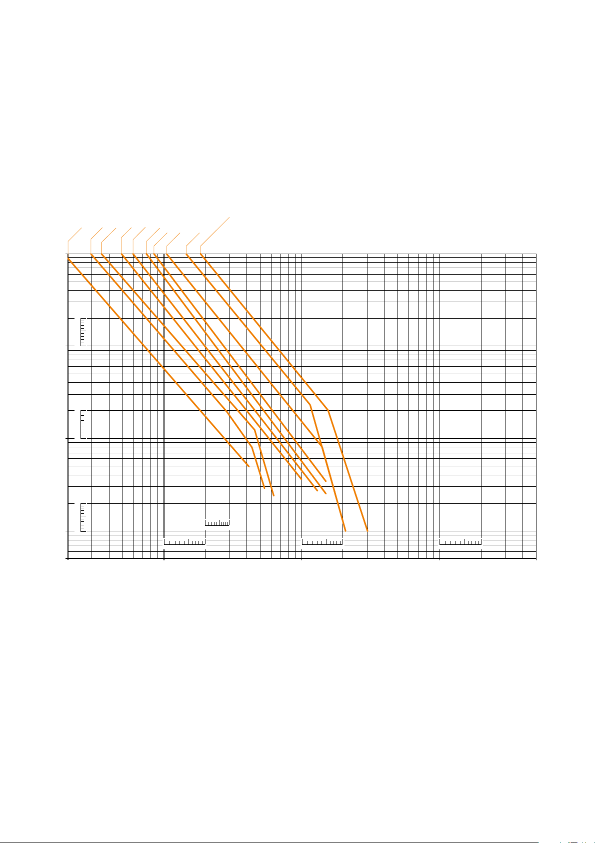
3-pole contactors
0.005
5000
Electrical durability
Electrical durability for AC-2 or AC-4 utilization category - 440 V < Ue ≤ 690 V
Ambient temperature ≤ 60 °C for AFS09 ... AFS96
Switching cage motors: starting, reverse operation and step-by-step operation. The breaking current Ic is equal to 2.5 x Ie for
AC-2 and 6 x Ie for AC-4, keaping in mind tha Ie is the motor rated operational current (Ie = motor full load current). Maximum
electrical switching frequency: see "Technical data".
Millions of
operating
cycles
AFS12
10
AFS09
AFS16
5
3
2
9
7
5
3
1
1
AFS26
AFS30
AFS38
AFS40
AFS52
AFS65
AFS80, AFS96
0.5
0.3
0.2
0.1
0.05
0.03
0.02
0.01
9
7
5
3
1
9
7
5
3
1
13579
13579
13579
13579
10001001023 5203050 200 300 500 2000 3000
Breaking current Ic (A)
1SBC100320S0201
ABB | 21
 Loading...