

Page 1

ACS800
Firmware Manual
ACS800 Standard Control Program 7.x
Page 2

Page 3

ACS800 Standard Control Program 7.x
Firmware Manual
© 2009 ABB Oy. All Rights Reserved.
3AFE64527592 REV K
EN
EFFECTIVE: 14.12.2009
Page 4

Page 5

Table of contents
Table of contents
Introduction to the manual
Chapter overview . . . . . . . . . . . . . . . . . . . . . . . . . . . . . . . . . . . . . . . . . . . . . . . . . . . . . . . . . . . . . . 13
Compatibility . . . . . . . . . . . . . . . . . . . . . . . . . . . . . . . . . . . . . . . . . . . . . . . . . . . . . . . . . . . . . . . . . . 13
Safety instructions . . . . . . . . . . . . . . . . . . . . . . . . . . . . . . . . . . . . . . . . . . . . . . . . . . . . . . . . . . . . . . 13
Reader . . . . . . . . . . . . . . . . . . . . . . . . . . . . . . . . . . . . . . . . . . . . . . . . . . . . . . . . . . . . . . . . . . . . . . . 13
Contents . . . . . . . . . . . . . . . . . . . . . . . . . . . . . . . . . . . . . . . . . . . . . . . . . . . . . . . . . . . . . . . . . . . . . 13
Product and service inquiries . . . . . . . . . . . . . . . . . . . . . . . . . . . . . . . . . . . . . . . . . . . . . . . . . . . . . 14
Product training . . . . . . . . . . . . . . . . . . . . . . . . . . . . . . . . . . . . . . . . . . . . . . . . . . . . . . . . . . . . . . . . 14
Providing feedback on ABB Drives manuals . . . . . . . . . . . . . . . . . . . . . . . . . . . . . . . . . . . . . . . . . . 14
Start-up and control through the I/O
5
Chapter overview . . . . . . . . . . . . . . . . . . . . . . . . . . . . . . . . . . . . . . . . . . . . . . . . . . . . . . . . . . . . . . 15
How to start-up the drive . . . . . . . . . . . . . . . . . . . . . . . . . . . . . . . . . . . . . . . . . . . . . . . . . . . . . . . . . 15
How to perform the guided start-up (covers all essential settings) . . . . . . . . . . . . . . . . . . . . . . . 15
How to perform the limited start-up (covers only the basic settings) . . . . . . . . . . . . . . . . . . . . . 17
How to control the drive through the I/O interface . . . . . . . . . . . . . . . . . . . . . . . . . . . . . . . . . . . . . . 21
How to perform the ID Run . . . . . . . . . . . . . . . . . . . . . . . . . . . . . . . . . . . . . . . . . . . . . . . . . . . . . . . 22
ID Run Procedure . . . . . . . . . . . . . . . . . . . . . . . . . . . . . . . . . . . . . . . . . . . . . . . . . . . . . . . . . . . . 22
Control panel
Chapter overview . . . . . . . . . . . . . . . . . . . . . . . . . . . . . . . . . . . . . . . . . . . . . . . . . . . . . . . . . . . . . . 25
Overview of the panel . . . . . . . . . . . . . . . . . . . . . . . . . . . . . . . . . . . . . . . . . . . . . . . . . . . . . . . . . . . 25
Panel operation mode keys and displays . . . . . . . . . . . . . . . . . . . . . . . . . . . . . . . . . . . . . . . . . . 26
Status row . . . . . . . . . . . . . . . . . . . . . . . . . . . . . . . . . . . . . . . . . . . . . . . . . . . . . . . . . . . . . . . . . . 26
Drive control with the panel . . . . . . . . . . . . . . . . . . . . . . . . . . . . . . . . . . . . . . . . . . . . . . . . . . . . . . . 27
How to start, stop and change direction . . . . . . . . . . . . . . . . . . . . . . . . . . . . . . . . . . . . . . . . . . . 27
How to set speed reference . . . . . . . . . . . . . . . . . . . . . . . . . . . . . . . . . . . . . . . . . . . . . . . . . . . . 28
Actual signal display mode . . . . . . . . . . . . . . . . . . . . . . . . . . . . . . . . . . . . . . . . . . . . . . . . . . . . . . . 29
How to select actual signals to the display . . . . . . . . . . . . . . . . . . . . . . . . . . . . . . . . . . . . . . . . . 29
How to display the full name of the actual signals . . . . . . . . . . . . . . . . . . . . . . . . . . . . . . . . . . . 30
How to view and reset the fault history . . . . . . . . . . . . . . . . . . . . . . . . . . . . . . . . . . . . . . . . . . . . 30
How to display and reset an active fault . . . . . . . . . . . . . . . . . . . . . . . . . . . . . . . . . . . . . . . . . . . 31
About the fault history . . . . . . . . . . . . . . . . . . . . . . . . . . . . . . . . . . . . . . . . . . . . . . . . . . . . . . . . . 31
Parameter mode . . . . . . . . . . . . . . . . . . . . . . . . . . . . . . . . . . . . . . . . . . . . . . . . . . . . . . . . . . . . . . . 32
How to select a parameter and change the value . . . . . . . . . . . . . . . . . . . . . . . . . . . . . . . . . . . 32
How to adjust a source selection (pointer) parameter . . . . . . . . . . . . . . . . . . . . . . . . . . . . . . . . 33
Function mode . . . . . . . . . . . . . . . . . . . . . . . . . . . . . . . . . . . . . . . . . . . . . . . . . . . . . . . . . . . . . . . . . 34
How to enter an assistant, browse and exit . . . . . . . . . . . . . . . . . . . . . . . . . . . . . . . . . . . . . . . . 35
How to upload data from a drive to the panel . . . . . . . . . . . . . . . . . . . . . . . . . . . . . . . . . . . . . . . 36
Table of contents
Page 6

6
How to download data from the panel to a drive . . . . . . . . . . . . . . . . . . . . . . . . . . . . . . . . . . . . 37
How to set the contrast of the display . . . . . . . . . . . . . . . . . . . . . . . . . . . . . . . . . . . . . . . . . . . . 38
Drive selection mode . . . . . . . . . . . . . . . . . . . . . . . . . . . . . . . . . . . . . . . . . . . . . . . . . . . . . . . . . . . 39
How to select a drive and change its panel link ID number . . . . . . . . . . . . . . . . . . . . . . . . . . . . 39
Reading and entering packed boolean values on the display . . . . . . . . . . . . . . . . . . . . . . . . . . . . 40
Program features
Chapter overview . . . . . . . . . . . . . . . . . . . . . . . . . . . . . . . . . . . . . . . . . . . . . . . . . . . . . . . . . . . . . . 41
Start-up Assistant . . . . . . . . . . . . . . . . . . . . . . . . . . . . . . . . . . . . . . . . . . . . . . . . . . . . . . . . . . . . . . 41
Introduction . . . . . . . . . . . . . . . . . . . . . . . . . . . . . . . . . . . . . . . . . . . . . . . . . . . . . . . . . . . . . . . . 41
The default order of the tasks . . . . . . . . . . . . . . . . . . . . . . . . . . . . . . . . . . . . . . . . . . . . . . . . . . 41
List of tasks and the relevant drive parameters . . . . . . . . . . . . . . . . . . . . . . . . . . . . . . . . . . . . . 42
Contents of the assistant displays . . . . . . . . . . . . . . . . . . . . . . . . . . . . . . . . . . . . . . . . . . . . . . . 43
Local control vs. external control . . . . . . . . . . . . . . . . . . . . . . . . . . . . . . . . . . . . . . . . . . . . . . . . . . 43
Local control . . . . . . . . . . . . . . . . . . . . . . . . . . . . . . . . . . . . . . . . . . . . . . . . . . . . . . . . . . . . . . . 44
External control . . . . . . . . . . . . . . . . . . . . . . . . . . . . . . . . . . . . . . . . . . . . . . . . . . . . . . . . . . . . . 44
Settings . . . . . . . . . . . . . . . . . . . . . . . . . . . . . . . . . . . . . . . . . . . . . . . . . . . . . . . . . . . . . . . . . . . 44
Diagnostics . . . . . . . . . . . . . . . . . . . . . . . . . . . . . . . . . . . . . . . . . . . . . . . . . . . . . . . . . . . . . . . . 44
Block diagram: start, stop, direction source for EXT1 . . . . . . . . . . . . . . . . . . . . . . . . . . . . . . . . 45
Block diagram: reference source for EXT1 . . . . . . . . . . . . . . . . . . . . . . . . . . . . . . . . . . . . . . . . 45
Reference types and processing . . . . . . . . . . . . . . . . . . . . . . . . . . . . . . . . . . . . . . . . . . . . . . . . . . 46
Settings . . . . . . . . . . . . . . . . . . . . . . . . . . . . . . . . . . . . . . . . . . . . . . . . . . . . . . . . . . . . . . . . . . . 46
Diagnostics . . . . . . . . . . . . . . . . . . . . . . . . . . . . . . . . . . . . . . . . . . . . . . . . . . . . . . . . . . . . . . . . 46
Reference trimming . . . . . . . . . . . . . . . . . . . . . . . . . . . . . . . . . . . . . . . . . . . . . . . . . . . . . . . . . . . . 47
Settings . . . . . . . . . . . . . . . . . . . . . . . . . . . . . . . . . . . . . . . . . . . . . . . . . . . . . . . . . . . . . . . . . . . 47
Example . . . . . . . . . . . . . . . . . . . . . . . . . . . . . . . . . . . . . . . . . . . . . . . . . . . . . . . . . . . . . . . . . . . 48
Programmable analogue inputs . . . . . . . . . . . . . . . . . . . . . . . . . . . . . . . . . . . . . . . . . . . . . . . . . . . 49
Update cycles in the Standard Control Program . . . . . . . . . . . . . . . . . . . . . . . . . . . . . . . . . . . . 49
Settings . . . . . . . . . . . . . . . . . . . . . . . . . . . . . . . . . . . . . . . . . . . . . . . . . . . . . . . . . . . . . . . . . . . 49
Diagnostics . . . . . . . . . . . . . . . . . . . . . . . . . . . . . . . . . . . . . . . . . . . . . . . . . . . . . . . . . . . . . . . . 49
Programmable analogue outputs . . . . . . . . . . . . . . . . . . . . . . . . . . . . . . . . . . . . . . . . . . . . . . . . . . 50
Update cycles in the Standard Control Program . . . . . . . . . . . . . . . . . . . . . . . . . . . . . . . . . . . . 50
Settings . . . . . . . . . . . . . . . . . . . . . . . . . . . . . . . . . . . . . . . . . . . . . . . . . . . . . . . . . . . . . . . . . . . 50
Diagnostics . . . . . . . . . . . . . . . . . . . . . . . . . . . . . . . . . . . . . . . . . . . . . . . . . . . . . . . . . . . . . . . . 50
Programmable digital inputs . . . . . . . . . . . . . . . . . . . . . . . . . . . . . . . . . . . . . . . . . . . . . . . . . . . . . . 51
Update cycles in the Standard Control Program . . . . . . . . . . . . . . . . . . . . . . . . . . . . . . . . . . . . 51
Settings . . . . . . . . . . . . . . . . . . . . . . . . . . . . . . . . . . . . . . . . . . . . . . . . . . . . . . . . . . . . . . . . . . . 51
Diagnostics . . . . . . . . . . . . . . . . . . . . . . . . . . . . . . . . . . . . . . . . . . . . . . . . . . . . . . . . . . . . . . . . 51
Programmable relay outputs . . . . . . . . . . . . . . . . . . . . . . . . . . . . . . . . . . . . . . . . . . . . . . . . . . . . . 52
Update cycles in the Standard Control Program . . . . . . . . . . . . . . . . . . . . . . . . . . . . . . . . . . . . 52
Settings . . . . . . . . . . . . . . . . . . . . . . . . . . . . . . . . . . . . . . . . . . . . . . . . . . . . . . . . . . . . . . . . . . . 52
Diagnostics . . . . . . . . . . . . . . . . . . . . . . . . . . . . . . . . . . . . . . . . . . . . . . . . . . . . . . . . . . . . . . . . 52
Actual signals . . . . . . . . . . . . . . . . . . . . . . . . . . . . . . . . . . . . . . . . . . . . . . . . . . . . . . . . . . . . . . . . . 53
Settings . . . . . . . . . . . . . . . . . . . . . . . . . . . . . . . . . . . . . . . . . . . . . . . . . . . . . . . . . . . . . . . . . . . 53
Diagnostics . . . . . . . . . . . . . . . . . . . . . . . . . . . . . . . . . . . . . . . . . . . . . . . . . . . . . . . . . . . . . . . . 53
Motor identification . . . . . . . . . . . . . . . . . . . . . . . . . . . . . . . . . . . . . . . . . . . . . . . . . . . . . . . . . . . . . 53
Settings . . . . . . . . . . . . . . . . . . . . . . . . . . . . . . . . . . . . . . . . . . . . . . . . . . . . . . . . . . . . . . . . . . . 53
Power loss ride-through . . . . . . . . . . . . . . . . . . . . . . . . . . . . . . . . . . . . . . . . . . . . . . . . . . . . . . . . . 54
Automatic Start . . . . . . . . . . . . . . . . . . . . . . . . . . . . . . . . . . . . . . . . . . . . . . . . . . . . . . . . . . . . . . . . 54
Table of contents
Page 7

Settings . . . . . . . . . . . . . . . . . . . . . . . . . . . . . . . . . . . . . . . . . . . . . . . . . . . . . . . . . . . . . . . . . . . . 54
DC Magnetising . . . . . . . . . . . . . . . . . . . . . . . . . . . . . . . . . . . . . . . . . . . . . . . . . . . . . . . . . . . . . . . . 55
Settings . . . . . . . . . . . . . . . . . . . . . . . . . . . . . . . . . . . . . . . . . . . . . . . . . . . . . . . . . . . . . . . . . . . . 55
DC Hold . . . . . . . . . . . . . . . . . . . . . . . . . . . . . . . . . . . . . . . . . . . . . . . . . . . . . . . . . . . . . . . . . . . . . . 55
Settings . . . . . . . . . . . . . . . . . . . . . . . . . . . . . . . . . . . . . . . . . . . . . . . . . . . . . . . . . . . . . . . . . . . . 55
Flux Braking . . . . . . . . . . . . . . . . . . . . . . . . . . . . . . . . . . . . . . . . . . . . . . . . . . . . . . . . . . . . . . . . . . 55
Settings . . . . . . . . . . . . . . . . . . . . . . . . . . . . . . . . . . . . . . . . . . . . . . . . . . . . . . . . . . . . . . . . . . . . 56
Flux Optimisation . . . . . . . . . . . . . . . . . . . . . . . . . . . . . . . . . . . . . . . . . . . . . . . . . . . . . . . . . . . . . . . 56
Settings . . . . . . . . . . . . . . . . . . . . . . . . . . . . . . . . . . . . . . . . . . . . . . . . . . . . . . . . . . . . . . . . . . . . 56
Acceleration and deceleration ramps . . . . . . . . . . . . . . . . . . . . . . . . . . . . . . . . . . . . . . . . . . . . . . . 57
Settings . . . . . . . . . . . . . . . . . . . . . . . . . . . . . . . . . . . . . . . . . . . . . . . . . . . . . . . . . . . . . . . . . . . . 57
Critical speeds . . . . . . . . . . . . . . . . . . . . . . . . . . . . . . . . . . . . . . . . . . . . . . . . . . . . . . . . . . . . . . . . . 57
Settings . . . . . . . . . . . . . . . . . . . . . . . . . . . . . . . . . . . . . . . . . . . . . . . . . . . . . . . . . . . . . . . . . . . . 57
Constant speeds . . . . . . . . . . . . . . . . . . . . . . . . . . . . . . . . . . . . . . . . . . . . . . . . . . . . . . . . . . . . . . . 57
Settings . . . . . . . . . . . . . . . . . . . . . . . . . . . . . . . . . . . . . . . . . . . . . . . . . . . . . . . . . . . . . . . . . . . . 57
Speed controller tuning . . . . . . . . . . . . . . . . . . . . . . . . . . . . . . . . . . . . . . . . . . . . . . . . . . . . . . . . . . 58
Settings . . . . . . . . . . . . . . . . . . . . . . . . . . . . . . . . . . . . . . . . . . . . . . . . . . . . . . . . . . . . . . . . . . . . 58
Diagnostics . . . . . . . . . . . . . . . . . . . . . . . . . . . . . . . . . . . . . . . . . . . . . . . . . . . . . . . . . . . . . . . . . 58
Speed control performance figures . . . . . . . . . . . . . . . . . . . . . . . . . . . . . . . . . . . . . . . . . . . . . . . . . 59
Torque control performance figures . . . . . . . . . . . . . . . . . . . . . . . . . . . . . . . . . . . . . . . . . . . . . . . . 59
Scalar control . . . . . . . . . . . . . . . . . . . . . . . . . . . . . . . . . . . . . . . . . . . . . . . . . . . . . . . . . . . . . . . . . 60
Settings . . . . . . . . . . . . . . . . . . . . . . . . . . . . . . . . . . . . . . . . . . . . . . . . . . . . . . . . . . . . . . . . . . . . 60
IR compensation for a scalar controlled drive . . . . . . . . . . . . . . . . . . . . . . . . . . . . . . . . . . . . . . . . . 60
Settings . . . . . . . . . . . . . . . . . . . . . . . . . . . . . . . . . . . . . . . . . . . . . . . . . . . . . . . . . . . . . . . . . . . . 60
Hexagonal motor flux . . . . . . . . . . . . . . . . . . . . . . . . . . . . . . . . . . . . . . . . . . . . . . . . . . . . . . . . . . . 61
Settings . . . . . . . . . . . . . . . . . . . . . . . . . . . . . . . . . . . . . . . . . . . . . . . . . . . . . . . . . . . . . . . . . . . . 61
Programmable protection functions . . . . . . . . . . . . . . . . . . . . . . . . . . . . . . . . . . . . . . . . . . . . . . . . . 61
AI<Min . . . . . . . . . . . . . . . . . . . . . . . . . . . . . . . . . . . . . . . . . . . . . . . . . . . . . . . . . . . . . . . . . . . . 61
Settings . . . . . . . . . . . . . . . . . . . . . . . . . . . . . . . . . . . . . . . . . . . . . . . . . . . . . . . . . . . . . . . . . 61
Panel Loss . . . . . . . . . . . . . . . . . . . . . . . . . . . . . . . . . . . . . . . . . . . . . . . . . . . . . . . . . . . . . . . . . 61
Settings . . . . . . . . . . . . . . . . . . . . . . . . . . . . . . . . . . . . . . . . . . . . . . . . . . . . . . . . . . . . . . . . . 61
External Fault . . . . . . . . . . . . . . . . . . . . . . . . . . . . . . . . . . . . . . . . . . . . . . . . . . . . . . . . . . . . . . . 61
Settings . . . . . . . . . . . . . . . . . . . . . . . . . . . . . . . . . . . . . . . . . . . . . . . . . . . . . . . . . . . . . . . . . 61
Motor Thermal Protection . . . . . . . . . . . . . . . . . . . . . . . . . . . . . . . . . . . . . . . . . . . . . . . . . . . . . . 62
Motor temperature thermal model . . . . . . . . . . . . . . . . . . . . . . . . . . . . . . . . . . . . . . . . . . . . . 62
Use of the motor thermistor . . . . . . . . . . . . . . . . . . . . . . . . . . . . . . . . . . . . . . . . . . . . . . . . . . 62
Settings . . . . . . . . . . . . . . . . . . . . . . . . . . . . . . . . . . . . . . . . . . . . . . . . . . . . . . . . . . . . . . . . . 62
Stall Protection . . . . . . . . . . . . . . . . . . . . . . . . . . . . . . . . . . . . . . . . . . . . . . . . . . . . . . . . . . . . . . 63
Settings . . . . . . . . . . . . . . . . . . . . . . . . . . . . . . . . . . . . . . . . . . . . . . . . . . . . . . . . . . . . . . . . . 63
Underload Protection . . . . . . . . . . . . . . . . . . . . . . . . . . . . . . . . . . . . . . . . . . . . . . . . . . . . . . . . . 63
Settings . . . . . . . . . . . . . . . . . . . . . . . . . . . . . . . . . . . . . . . . . . . . . . . . . . . . . . . . . . . . . . . . . 63
Motor Phase Loss . . . . . . . . . . . . . . . . . . . . . . . . . . . . . . . . . . . . . . . . . . . . . . . . . . . . . . . . . . . . 63
Settings . . . . . . . . . . . . . . . . . . . . . . . . . . . . . . . . . . . . . . . . . . . . . . . . . . . . . . . . . . . . . . . . . 63
Earth Fault Protection . . . . . . . . . . . . . . . . . . . . . . . . . . . . . . . . . . . . . . . . . . . . . . . . . . . . . . . . . 64
Settings . . . . . . . . . . . . . . . . . . . . . . . . . . . . . . . . . . . . . . . . . . . . . . . . . . . . . . . . . . . . . . . . . 64
Communication Fault . . . . . . . . . . . . . . . . . . . . . . . . . . . . . . . . . . . . . . . . . . . . . . . . . . . . . . . . . 64
Settings . . . . . . . . . . . . . . . . . . . . . . . . . . . . . . . . . . . . . . . . . . . . . . . . . . . . . . . . . . . . . . . . . 64
Supervision of optional IO . . . . . . . . . . . . . . . . . . . . . . . . . . . . . . . . . . . . . . . . . . . . . . . . . . . . . 64
Settings . . . . . . . . . . . . . . . . . . . . . . . . . . . . . . . . . . . . . . . . . . . . . . . . . . . . . . . . . . . . . . . . . 64
Preprogrammed faults . . . . . . . . . . . . . . . . . . . . . . . . . . . . . . . . . . . . . . . . . . . . . . . . . . . . . . . . . . . 64
7
Table of contents
Page 8

8
Overcurrent . . . . . . . . . . . . . . . . . . . . . . . . . . . . . . . . . . . . . . . . . . . . . . . . . . . . . . . . . . . . . . . . 64
DC overvoltage . . . . . . . . . . . . . . . . . . . . . . . . . . . . . . . . . . . . . . . . . . . . . . . . . . . . . . . . . . . . . 64
DC undervoltage . . . . . . . . . . . . . . . . . . . . . . . . . . . . . . . . . . . . . . . . . . . . . . . . . . . . . . . . . . . . 65
Drive temperature . . . . . . . . . . . . . . . . . . . . . . . . . . . . . . . . . . . . . . . . . . . . . . . . . . . . . . . . . . . 65
Enhanced drive temperature monitoring for ACS800, frame sizes R7 and R8 . . . . . . . . . . . . . 65
Settings . . . . . . . . . . . . . . . . . . . . . . . . . . . . . . . . . . . . . . . . . . . . . . . . . . . . . . . . . . . . . . . . . 66
Diagnostics . . . . . . . . . . . . . . . . . . . . . . . . . . . . . . . . . . . . . . . . . . . . . . . . . . . . . . . . . . . . . . 66
Short circuit . . . . . . . . . . . . . . . . . . . . . . . . . . . . . . . . . . . . . . . . . . . . . . . . . . . . . . . . . . . . . . . . 66
Input phase loss . . . . . . . . . . . . . . . . . . . . . . . . . . . . . . . . . . . . . . . . . . . . . . . . . . . . . . . . . . . . . 66
Control board temperature . . . . . . . . . . . . . . . . . . . . . . . . . . . . . . . . . . . . . . . . . . . . . . . . . . . . . 66
Overfrequency . . . . . . . . . . . . . . . . . . . . . . . . . . . . . . . . . . . . . . . . . . . . . . . . . . . . . . . . . . . . . . 66
Internal fault . . . . . . . . . . . . . . . . . . . . . . . . . . . . . . . . . . . . . . . . . . . . . . . . . . . . . . . . . . . . . . . . 66
Operation limits . . . . . . . . . . . . . . . . . . . . . . . . . . . . . . . . . . . . . . . . . . . . . . . . . . . . . . . . . . . . . . . 66
Settings . . . . . . . . . . . . . . . . . . . . . . . . . . . . . . . . . . . . . . . . . . . . . . . . . . . . . . . . . . . . . . . . . . . 66
Power limit . . . . . . . . . . . . . . . . . . . . . . . . . . . . . . . . . . . . . . . . . . . . . . . . . . . . . . . . . . . . . . . . . . . 67
Automatic resets . . . . . . . . . . . . . . . . . . . . . . . . . . . . . . . . . . . . . . . . . . . . . . . . . . . . . . . . . . . . . . . 67
Settings . . . . . . . . . . . . . . . . . . . . . . . . . . . . . . . . . . . . . . . . . . . . . . . . . . . . . . . . . . . . . . . . . . . 67
Supervisions . . . . . . . . . . . . . . . . . . . . . . . . . . . . . . . . . . . . . . . . . . . . . . . . . . . . . . . . . . . . . . . . . . 67
Settings . . . . . . . . . . . . . . . . . . . . . . . . . . . . . . . . . . . . . . . . . . . . . . . . . . . . . . . . . . . . . . . . . . . 67
Diagnostics . . . . . . . . . . . . . . . . . . . . . . . . . . . . . . . . . . . . . . . . . . . . . . . . . . . . . . . . . . . . . . . . 67
Parameter lock . . . . . . . . . . . . . . . . . . . . . . . . . . . . . . . . . . . . . . . . . . . . . . . . . . . . . . . . . . . . . . . . 67
Settings . . . . . . . . . . . . . . . . . . . . . . . . . . . . . . . . . . . . . . . . . . . . . . . . . . . . . . . . . . . . . . . . . . . 67
Process PID control . . . . . . . . . . . . . . . . . . . . . . . . . . . . . . . . . . . . . . . . . . . . . . . . . . . . . . . . . . . . 68
Block diagrams . . . . . . . . . . . . . . . . . . . . . . . . . . . . . . . . . . . . . . . . . . . . . . . . . . . . . . . . . . . . . 68
Settings . . . . . . . . . . . . . . . . . . . . . . . . . . . . . . . . . . . . . . . . . . . . . . . . . . . . . . . . . . . . . . . . . . . 69
Diagnostics . . . . . . . . . . . . . . . . . . . . . . . . . . . . . . . . . . . . . . . . . . . . . . . . . . . . . . . . . . . . . . . . 69
Sleep function for the process PID control . . . . . . . . . . . . . . . . . . . . . . . . . . . . . . . . . . . . . . . . . . . 69
Example . . . . . . . . . . . . . . . . . . . . . . . . . . . . . . . . . . . . . . . . . . . . . . . . . . . . . . . . . . . . . . . . . . . 70
Settings . . . . . . . . . . . . . . . . . . . . . . . . . . . . . . . . . . . . . . . . . . . . . . . . . . . . . . . . . . . . . . . . . . . 70
Diagnostics . . . . . . . . . . . . . . . . . . . . . . . . . . . . . . . . . . . . . . . . . . . . . . . . . . . . . . . . . . . . . . . . 70
Motor temperature measurement through the standard I/O . . . . . . . . . . . . . . . . . . . . . . . . . . . . . . 71
Settings . . . . . . . . . . . . . . . . . . . . . . . . . . . . . . . . . . . . . . . . . . . . . . . . . . . . . . . . . . . . . . . . . . . 72
Diagnostics . . . . . . . . . . . . . . . . . . . . . . . . . . . . . . . . . . . . . . . . . . . . . . . . . . . . . . . . . . . . . . . . 72
Motor temperature measurement through an analogue I/O extension . . . . . . . . . . . . . . . . . . . . . . 73
Settings . . . . . . . . . . . . . . . . . . . . . . . . . . . . . . . . . . . . . . . . . . . . . . . . . . . . . . . . . . . . . . . . . . . 74
Diagnostics . . . . . . . . . . . . . . . . . . . . . . . . . . . . . . . . . . . . . . . . . . . . . . . . . . . . . . . . . . . . . . . . 74
Adaptive Programming using the function blocks . . . . . . . . . . . . . . . . . . . . . . . . . . . . . . . . . . . . . 74
DriveAP . . . . . . . . . . . . . . . . . . . . . . . . . . . . . . . . . . . . . . . . . . . . . . . . . . . . . . . . . . . . . . . . . . . 74
Control of a mechanical brake . . . . . . . . . . . . . . . . . . . . . . . . . . . . . . . . . . . . . . . . . . . . . . . . . . . . 75
Example . . . . . . . . . . . . . . . . . . . . . . . . . . . . . . . . . . . . . . . . . . . . . . . . . . . . . . . . . . . . . . . . . . . 75
Operation time scheme . . . . . . . . . . . . . . . . . . . . . . . . . . . . . . . . . . . . . . . . . . . . . . . . . . . . . . . 76
State shifts . . . . . . . . . . . . . . . . . . . . . . . . . . . . . . . . . . . . . . . . . . . . . . . . . . . . . . . . . . . . . . . . . 77
Settings . . . . . . . . . . . . . . . . . . . . . . . . . . . . . . . . . . . . . . . . . . . . . . . . . . . . . . . . . . . . . . . . . . . 78
Diagnostics . . . . . . . . . . . . . . . . . . . . . . . . . . . . . . . . . . . . . . . . . . . . . . . . . . . . . . . . . . . . . . . . 78
Master/Follower use of several drives . . . . . . . . . . . . . . . . . . . . . . . . . . . . . . . . . . . . . . . . . . . . . . 78
Settings and diagnostics . . . . . . . . . . . . . . . . . . . . . . . . . . . . . . . . . . . . . . . . . . . . . . . . . . . . . . 78
Jogging . . . . . . . . . . . . . . . . . . . . . . . . . . . . . . . . . . . . . . . . . . . . . . . . . . . . . . . . . . . . . . . . . . . . . . 79
Settings . . . . . . . . . . . . . . . . . . . . . . . . . . . . . . . . . . . . . . . . . . . . . . . . . . . . . . . . . . . . . . . . . . . 80
Reduced Run function . . . . . . . . . . . . . . . . . . . . . . . . . . . . . . . . . . . . . . . . . . . . . . . . . . . . . . . . . . 80
Settings . . . . . . . . . . . . . . . . . . . . . . . . . . . . . . . . . . . . . . . . . . . . . . . . . . . . . . . . . . . . . . . . . . . 80
Table of contents
Page 9

Diagnostics . . . . . . . . . . . . . . . . . . . . . . . . . . . . . . . . . . . . . . . . . . . . . . . . . . . . . . . . . . . . . . . . . 80
User load curve . . . . . . . . . . . . . . . . . . . . . . . . . . . . . . . . . . . . . . . . . . . . . . . . . . . . . . . . . . . . . . . . 81
Overload . . . . . . . . . . . . . . . . . . . . . . . . . . . . . . . . . . . . . . . . . . . . . . . . . . . . . . . . . . . . . . . . . . . 81
Settings . . . . . . . . . . . . . . . . . . . . . . . . . . . . . . . . . . . . . . . . . . . . . . . . . . . . . . . . . . . . . . . . . . . . 82
Diagnostics . . . . . . . . . . . . . . . . . . . . . . . . . . . . . . . . . . . . . . . . . . . . . . . . . . . . . . . . . . . . . . . . . 82
Application macros
Chapter overview . . . . . . . . . . . . . . . . . . . . . . . . . . . . . . . . . . . . . . . . . . . . . . . . . . . . . . . . . . . . . . 83
Overview of macros . . . . . . . . . . . . . . . . . . . . . . . . . . . . . . . . . . . . . . . . . . . . . . . . . . . . . . . . . . . . . 83
Note on external power supply . . . . . . . . . . . . . . . . . . . . . . . . . . . . . . . . . . . . . . . . . . . . . . . . . . . . 84
Parameter settings . . . . . . . . . . . . . . . . . . . . . . . . . . . . . . . . . . . . . . . . . . . . . . . . . . . . . . . . . . . 84
Factory macro . . . . . . . . . . . . . . . . . . . . . . . . . . . . . . . . . . . . . . . . . . . . . . . . . . . . . . . . . . . . . . . . . 85
Default control connections . . . . . . . . . . . . . . . . . . . . . . . . . . . . . . . . . . . . . . . . . . . . . . . . . . . . 86
Hand/Auto macro . . . . . . . . . . . . . . . . . . . . . . . . . . . . . . . . . . . . . . . . . . . . . . . . . . . . . . . . . . . . . . 87
Default control connections . . . . . . . . . . . . . . . . . . . . . . . . . . . . . . . . . . . . . . . . . . . . . . . . . . . . 88
PID Control macro . . . . . . . . . . . . . . . . . . . . . . . . . . . . . . . . . . . . . . . . . . . . . . . . . . . . . . . . . . . . . . 89
Connection example, 24 VDC / 4…20 mA two-wire sensor . . . . . . . . . . . . . . . . . . . . . . . . . . . . 89
Default control connections . . . . . . . . . . . . . . . . . . . . . . . . . . . . . . . . . . . . . . . . . . . . . . . . . . . . 90
Torque Control macro . . . . . . . . . . . . . . . . . . . . . . . . . . . . . . . . . . . . . . . . . . . . . . . . . . . . . . . . . . . 91
Default control connections . . . . . . . . . . . . . . . . . . . . . . . . . . . . . . . . . . . . . . . . . . . . . . . . . . . . 92
Sequential Control macro . . . . . . . . . . . . . . . . . . . . . . . . . . . . . . . . . . . . . . . . . . . . . . . . . . . . . . . . 93
Operation diagram . . . . . . . . . . . . . . . . . . . . . . . . . . . . . . . . . . . . . . . . . . . . . . . . . . . . . . . . . . . 93
Default control connections . . . . . . . . . . . . . . . . . . . . . . . . . . . . . . . . . . . . . . . . . . . . . . . . . . . . 94
User macros . . . . . . . . . . . . . . . . . . . . . . . . . . . . . . . . . . . . . . . . . . . . . . . . . . . . . . . . . . . . . . . . . . 95
9
Actual signals and parameters
Chapter overview . . . . . . . . . . . . . . . . . . . . . . . . . . . . . . . . . . . . . . . . . . . . . . . . . . . . . . . . . . . . . . 97
Terms and abbreviations . . . . . . . . . . . . . . . . . . . . . . . . . . . . . . . . . . . . . . . . . . . . . . . . . . . . . . . . . 97
01 ACTUAL SIGNALS . . . . . . . . . . . . . . . . . . . . . . . . . . . . . . . . . . . . . . . . . . . . . . . . . . . . . . . . . . . 98
02 ACTUAL SIGNALS . . . . . . . . . . . . . . . . . . . . . . . . . . . . . . . . . . . . . . . . . . . . . . . . . . . . . . . . . . 100
03 ACTUAL SIGNALS . . . . . . . . . . . . . . . . . . . . . . . . . . . . . . . . . . . . . . . . . . . . . . . . . . . . . . . . . . 100
04 ACTUAL SIGNALS . . . . . . . . . . . . . . . . . . . . . . . . . . . . . . . . . . . . . . . . . . . . . . . . . . . . . . . . . . 101
09 ACTUAL SIGNALS . . . . . . . . . . . . . . . . . . . . . . . . . . . . . . . . . . . . . . . . . . . . . . . . . . . . . . . . . . 101
10 START/STOP/DIR . . . . . . . . . . . . . . . . . . . . . . . . . . . . . . . . . . . . . . . . . . . . . . . . . . . . . . . . . . 103
11 REFERENCE SELECT . . . . . . . . . . . . . . . . . . . . . . . . . . . . . . . . . . . . . . . . . . . . . . . . . . . . . . 105
12 CONSTANT SPEEDS . . . . . . . . . . . . . . . . . . . . . . . . . . . . . . . . . . . . . . . . . . . . . . . . . . . . . . . 110
13 ANALOGUE INPUTS . . . . . . . . . . . . . . . . . . . . . . . . . . . . . . . . . . . . . . . . . . . . . . . . . . . . . . . . 113
14 RELAY OUTPUTS . . . . . . . . . . . . . . . . . . . . . . . . . . . . . . . . . . . . . . . . . . . . . . . . . . . . . . . . . . 116
15 ANALOGUE OUTPUTS . . . . . . . . . . . . . . . . . . . . . . . . . . . . . . . . . . . . . . . . . . . . . . . . . . . . . . 122
16 SYST CTRL INPUTS . . . . . . . . . . . . . . . . . . . . . . . . . . . . . . . . . . . . . . . . . . . . . . . . . . . . . . . . 124
20 LIMITS . . . . . . . . . . . . . . . . . . . . . . . . . . . . . . . . . . . . . . . . . . . . . . . . . . . . . . . . . . . . . . . . . . . 127
21 START/STOP . . . . . . . . . . . . . . . . . . . . . . . . . . . . . . . . . . . . . . . . . . . . . . . . . . . . . . . . . . . . . . 129
22 ACCEL/DECEL . . . . . . . . . . . . . . . . . . . . . . . . . . . . . . . . . . . . . . . . . . . . . . . . . . . . . . . . . . . . 132
23 SPEED CTRL . . . . . . . . . . . . . . . . . . . . . . . . . . . . . . . . . . . . . . . . . . . . . . . . . . . . . . . . . . . . . . 135
24 TORQUE CTRL . . . . . . . . . . . . . . . . . . . . . . . . . . . . . . . . . . . . . . . . . . . . . . . . . . . . . . . . . . . . 137
25 CRITICAL SPEEDS . . . . . . . . . . . . . . . . . . . . . . . . . . . . . . . . . . . . . . . . . . . . . . . . . . . . . . . . . 137
26 MOTOR CONTROL . . . . . . . . . . . . . . . . . . . . . . . . . . . . . . . . . . . . . . . . . . . . . . . . . . . . . . . . . 138
27 BRAKE CHOPPER . . . . . . . . . . . . . . . . . . . . . . . . . . . . . . . . . . . . . . . . . . . . . . . . . . . . . . . . . 140
Table of contents
Page 10

10
30 FAULT FUNCTIONS . . . . . . . . . . . . . . . . . . . . . . . . . . . . . . . . . . . . . . . . . . . . . . . . . . . . . . . . 141
31 AUTOMATIC RESET . . . . . . . . . . . . . . . . . . . . . . . . . . . . . . . . . . . . . . . . . . . . . . . . . . . . . . . 147
32 SUPERVISION . . . . . . . . . . . . . . . . . . . . . . . . . . . . . . . . . . . . . . . . . . . . . . . . . . . . . . . . . . . . 148
33 INFORMATION . . . . . . . . . . . . . . . . . . . . . . . . . . . . . . . . . . . . . . . . . . . . . . . . . . . . . . . . . . . . 149
34 PROCESS VARIABLE . . . . . . . . . . . . . . . . . . . . . . . . . . . . . . . . . . . . . . . . . . . . . . . . . . . . . . 150
35 MOT TEMP MEAS . . . . . . . . . . . . . . . . . . . . . . . . . . . . . . . . . . . . . . . . . . . . . . . . . . . . . . . . . 152
40 PID CONTROL . . . . . . . . . . . . . . . . . . . . . . . . . . . . . . . . . . . . . . . . . . . . . . . . . . . . . . . . . . . . 154
42 BRAKE CONTROL . . . . . . . . . . . . . . . . . . . . . . . . . . . . . . . . . . . . . . . . . . . . . . . . . . . . . . . . . 159
45 ENERGY OPT . . . . . . . . . . . . . . . . . . . . . . . . . . . . . . . . . . . . . . . . . . . . . . . . . . . . . . . . . . . . . 161
50 ENCODER MODULE . . . . . . . . . . . . . . . . . . . . . . . . . . . . . . . . . . . . . . . . . . . . . . . . . . . . . . . 162
51 COMM MODULE DATA . . . . . . . . . . . . . . . . . . . . . . . . . . . . . . . . . . . . . . . . . . . . . . . . . . . . . 163
52 STANDARD MODBUS . . . . . . . . . . . . . . . . . . . . . . . . . . . . . . . . . . . . . . . . . . . . . . . . . . . . . . 163
60 MASTER/FOLLOWER . . . . . . . . . . . . . . . . . . . . . . . . . . . . . . . . . . . . . . . . . . . . . . . . . . . . . . 163
70 DDCS CONTROL . . . . . . . . . . . . . . . . . . . . . . . . . . . . . . . . . . . . . . . . . . . . . . . . . . . . . . . . . . 165
72 USER LOAD CURVE . . . . . . . . . . . . . . . . . . . . . . . . . . . . . . . . . . . . . . . . . . . . . . . . . . . . . . . 166
83 ADAPT PROG CTRL . . . . . . . . . . . . . . . . . . . . . . . . . . . . . . . . . . . . . . . . . . . . . . . . . . . . . . . 168
84 ADAPTIVE PROGRAM . . . . . . . . . . . . . . . . . . . . . . . . . . . . . . . . . . . . . . . . . . . . . . . . . . . . . . 169
85 USER CONSTANTS . . . . . . . . . . . . . . . . . . . . . . . . . . . . . . . . . . . . . . . . . . . . . . . . . . . . . . . . 170
90 D SET REC ADDR . . . . . . . . . . . . . . . . . . . . . . . . . . . . . . . . . . . . . . . . . . . . . . . . . . . . . . . . . 171
92 D SET TR ADDR . . . . . . . . . . . . . . . . . . . . . . . . . . . . . . . . . . . . . . . . . . . . . . . . . . . . . . . . . . . 172
95 HARDWARE SPECIF . . . . . . . . . . . . . . . . . . . . . . . . . . . . . . . . . . . . . . . . . . . . . . . . . . . . . . . 172
96 EXTERNAL AO . . . . . . . . . . . . . . . . . . . . . . . . . . . . . . . . . . . . . . . . . . . . . . . . . . . . . . . . . . . . 175
98 OPTION MODULES . . . . . . . . . . . . . . . . . . . . . . . . . . . . . . . . . . . . . . . . . . . . . . . . . . . . . . . . 177
99 START-UP DATA . . . . . . . . . . . . . . . . . . . . . . . . . . . . . . . . . . . . . . . . . . . . . . . . . . . . . . . . . . 183
Fieldbus control
Chapter overview . . . . . . . . . . . . . . . . . . . . . . . . . . . . . . . . . . . . . . . . . . . . . . . . . . . . . . . . . . . . . 187
System overview . . . . . . . . . . . . . . . . . . . . . . . . . . . . . . . . . . . . . . . . . . . . . . . . . . . . . . . . . . . . . 187
Redundant fieldbus control . . . . . . . . . . . . . . . . . . . . . . . . . . . . . . . . . . . . . . . . . . . . . . . . . . . 188
Setting up communication through a fieldbus adapter module . . . . . . . . . . . . . . . . . . . . . . . . . . 189
Setting up communication through the Standard Modbus Link . . . . . . . . . . . . . . . . . . . . . . . . . . 191
Modbus addressing . . . . . . . . . . . . . . . . . . . . . . . . . . . . . . . . . . . . . . . . . . . . . . . . . . . . . . . 192
Setting up communication through Advant controller . . . . . . . . . . . . . . . . . . . . . . . . . . . . . . . . . . 193
Drive control parameters . . . . . . . . . . . . . . . . . . . . . . . . . . . . . . . . . . . . . . . . . . . . . . . . . . . . . . . 195
The fieldbus control interface . . . . . . . . . . . . . . . . . . . . . . . . . . . . . . . . . . . . . . . . . . . . . . . . . . . . 198
The Control Word and the Status Word . . . . . . . . . . . . . . . . . . . . . . . . . . . . . . . . . . . . . . . . . . 199
References . . . . . . . . . . . . . . . . . . . . . . . . . . . . . . . . . . . . . . . . . . . . . . . . . . . . . . . . . . . . . . . 199
Fieldbus reference selection and correction . . . . . . . . . . . . . . . . . . . . . . . . . . . . . . . . . . . . 199
Reference handling . . . . . . . . . . . . . . . . . . . . . . . . . . . . . . . . . . . . . . . . . . . . . . . . . . . . . . . . . 200
Actual Values . . . . . . . . . . . . . . . . . . . . . . . . . . . . . . . . . . . . . . . . . . . . . . . . . . . . . . . . . . . . . . 201
Block diagram: Control data input from fieldbus when a type Rxxx fieldbus adapter is used . 202
Block diagram: Actual value selection for fieldbus when a type Rxxx fieldbus adapter is used 203
Block diagram: Control data input from fieldbus when a type Nxxx fieldbus adapter is used . 204
Block Diagram: Actual value selection for fieldbus when a type Nxxx fieldbus adapter is used 205
Communication profiles . . . . . . . . . . . . . . . . . . . . . . . . . . . . . . . . . . . . . . . . . . . . . . . . . . . . . . . . 206
ABB Drives communication profile . . . . . . . . . . . . . . . . . . . . . . . . . . . . . . . . . . . . . . . . . . . . . 206
03.01 MAIN CONTROL WORD . . . . . . . . . . . . . . . . . . . . . . . . . . . . . . . . . . . . . . . . . . . . . 207
03.02 MAIN STATUS WORD . . . . . . . . . . . . . . . . . . . . . . . . . . . . . . . . . . . . . . . . . . . . . . . 208
Fieldbus reference scaling . . . . . . . . . . . . . . . . . . . . . . . . . . . . . . . . . . . . . . . . . . . . . . . . . 210
Table of contents
Page 11

11
Generic Drive communication profile . . . . . . . . . . . . . . . . . . . . . . . . . . . . . . . . . . . . . . . . . . . . 211
Drive commands supported by the Generic Drive communication profile . . . . . . . . . . . . . . 212
Fieldbus reference scaling . . . . . . . . . . . . . . . . . . . . . . . . . . . . . . . . . . . . . . . . . . . . . . . . . . 213
CSA 2.8/3.0 communication profile . . . . . . . . . . . . . . . . . . . . . . . . . . . . . . . . . . . . . . . . . . . . . 214
CONTROL WORD for the CSA 2.8/3.0 communication profile . . . . . . . . . . . . . . . . . . . . . . 214
STATUS WORD for the CSA 2.8/3.0 communication profile . . . . . . . . . . . . . . . . . . . . . . . . 214
Diverse status, fault, alarm and limit words . . . . . . . . . . . . . . . . . . . . . . . . . . . . . . . . . . . . . . . . . . 215
03.03 AUXILIARY STATUS WORD . . . . . . . . . . . . . . . . . . . . . . . . . . . . . . . . . . . . . . . . . . . 215
03.04 LIMIT WORD 1 . . . . . . . . . . . . . . . . . . . . . . . . . . . . . . . . . . . . . . . . . . . . . . . . . . . . . 216
03.05 FAULT WORD 1 . . . . . . . . . . . . . . . . . . . . . . . . . . . . . . . . . . . . . . . . . . . . . . . . . . . . 216
03.06 FAULT WORD 2 . . . . . . . . . . . . . . . . . . . . . . . . . . . . . . . . . . . . . . . . . . . . . . . . . . . . 217
03.07 SYSTEM FAULT WORD . . . . . . . . . . . . . . . . . . . . . . . . . . . . . . . . . . . . . . . . . . . . . . 218
03.08 ALARM WORD 1 . . . . . . . . . . . . . . . . . . . . . . . . . . . . . . . . . . . . . . . . . . . . . . . . . . . . 218
03.09 ALARM WORD 2 . . . . . . . . . . . . . . . . . . . . . . . . . . . . . . . . . . . . . . . . . . . . . . . . . . . . 219
03.13 AUXILIARY STATUS WORD 3 . . . . . . . . . . . . . . . . . . . . . . . . . . . . . . . . . . . . . . . . . 219
03.14 AUXILIARY STATUS WORD 4 . . . . . . . . . . . . . . . . . . . . . . . . . . . . . . . . . . . . . . . . . 220
03.15 FAULT WORD 4 . . . . . . . . . . . . . . . . . . . . . . . . . . . . . . . . . . . . . . . . . . . . . . . . . . . . 220
03.16 ALARM WORD 4 . . . . . . . . . . . . . . . . . . . . . . . . . . . . . . . . . . . . . . . . . . . . . . . . . . . . 221
03.17 FAULT WORD 5 . . . . . . . . . . . . . . . . . . . . . . . . . . . . . . . . . . . . . . . . . . . . . . . . . . . . 221
03.18 ALARM WORD 5 . . . . . . . . . . . . . . . . . . . . . . . . . . . . . . . . . . . . . . . . . . . . . . . . . . . . 222
03.19 INT INIT FAULT . . . . . . . . . . . . . . . . . . . . . . . . . . . . . . . . . . . . . . . . . . . . . . . . . . . . . 222
03.30 LIMIT WORD INV . . . . . . . . . . . . . . . . . . . . . . . . . . . . . . . . . . . . . . . . . . . . . . . . . . . 223
03.31 ALARM WORD 6 . . . . . . . . . . . . . . . . . . . . . . . . . . . . . . . . . . . . . . . . . . . . . . . . . . . . 223
03.32 EXT IO STATUS . . . . . . . . . . . . . . . . . . . . . . . . . . . . . . . . . . . . . . . . . . . . . . . . . . . . 224
03.33 FAULT WORD 6 . . . . . . . . . . . . . . . . . . . . . . . . . . . . . . . . . . . . . . . . . . . . . . . . . . . . 224
04.01 FAULTED INT INFO . . . . . . . . . . . . . . . . . . . . . . . . . . . . . . . . . . . . . . . . . . . . . . . . . 225
04.02 INT SC INFO . . . . . . . . . . . . . . . . . . . . . . . . . . . . . . . . . . . . . . . . . . . . . . . . . . . . . . . 226
Fault tracing
Chapter overview . . . . . . . . . . . . . . . . . . . . . . . . . . . . . . . . . . . . . . . . . . . . . . . . . . . . . . . . . . . . . 227
Safety . . . . . . . . . . . . . . . . . . . . . . . . . . . . . . . . . . . . . . . . . . . . . . . . . . . . . . . . . . . . . . . . . . . . . . 227
Warning and fault indications . . . . . . . . . . . . . . . . . . . . . . . . . . . . . . . . . . . . . . . . . . . . . . . . . . . . 227
How to reset . . . . . . . . . . . . . . . . . . . . . . . . . . . . . . . . . . . . . . . . . . . . . . . . . . . . . . . . . . . . . . . . . 227
Fault history . . . . . . . . . . . . . . . . . . . . . . . . . . . . . . . . . . . . . . . . . . . . . . . . . . . . . . . . . . . . . . . . . . 227
Warning messages generated by the drive . . . . . . . . . . . . . . . . . . . . . . . . . . . . . . . . . . . . . . . . . . 228
Warning messages generated by the control panel . . . . . . . . . . . . . . . . . . . . . . . . . . . . . . . . . . . 235
Fault messages generated by the drive . . . . . . . . . . . . . . . . . . . . . . . . . . . . . . . . . . . . . . . . . . . . 236
Analogue Extension Module
Chapter overview . . . . . . . . . . . . . . . . . . . . . . . . . . . . . . . . . . . . . . . . . . . . . . . . . . . . . . . . . . . . . 245
Speed control through the analogue extension module . . . . . . . . . . . . . . . . . . . . . . . . . . . . . . . . 245
Basic checks . . . . . . . . . . . . . . . . . . . . . . . . . . . . . . . . . . . . . . . . . . . . . . . . . . . . . . . . . . . . . . . 245
Settings of the analogue extension module and the drive . . . . . . . . . . . . . . . . . . . . . . . . . . . . 245
Parameter settings: bipolar input in basic speed control . . . . . . . . . . . . . . . . . . . . . . . . . . . . . . . . 246
Parameter settings: bipolar input in joystick mode . . . . . . . . . . . . . . . . . . . . . . . . . . . . . . . . . . . . 247
Table of contents
Page 12

12
Additional data: actual signals and parameters
Chapter overview . . . . . . . . . . . . . . . . . . . . . . . . . . . . . . . . . . . . . . . . . . . . . . . . . . . . . . . . . . . . . 249
Terms and abbreviations . . . . . . . . . . . . . . . . . . . . . . . . . . . . . . . . . . . . . . . . . . . . . . . . . . . . . . . 249
Fieldbus addresses . . . . . . . . . . . . . . . . . . . . . . . . . . . . . . . . . . . . . . . . . . . . . . . . . . . . . . . . . . . 249
Rxxx adapter modules (such as RPBA-01, RDNA-01, etc.) . . . . . . . . . . . . . . . . . . . . . . . . . . 249
Nxxx adapter modules (such as NPBA-12, NDNA-02, etc.) . . . . . . . . . . . . . . . . . . . . . . . . . . 249
NPBA-12 Profibus Adapter . . . . . . . . . . . . . . . . . . . . . . . . . . . . . . . . . . . . . . . . . . . . . . . . . 249
NIBA-01 InterBus-S Adapter . . . . . . . . . . . . . . . . . . . . . . . . . . . . . . . . . . . . . . . . . . . . . . . . 250
NMBP-01 ModbusPlus® Adapter and NMBA-01 Modbus Adapter . . . . . . . . . . . . . . . . . . . 250
Actual signals . . . . . . . . . . . . . . . . . . . . . . . . . . . . . . . . . . . . . . . . . . . . . . . . . . . . . . . . . . . . . . . . 251
Parameters . . . . . . . . . . . . . . . . . . . . . . . . . . . . . . . . . . . . . . . . . . . . . . . . . . . . . . . . . . . . . . . . . . 254
Control block diagrams
Chapter overview . . . . . . . . . . . . . . . . . . . . . . . . . . . . . . . . . . . . . . . . . . . . . . . . . . . . . . . . . . . . . 263
Reference control chain, sheet 1: FACTORY, HAND/AUTO, SEQ CTRL and T CTRL macros
(continued on the next page …) . . . . . . . . . . . . . . . . . . . . . . . . . . . . . . . . . . . . . . . . . . . . . . . . . . 264
Reference control chain sheet 1: PID CTRL macro (continued on the next page …) . . . . . . . . . 266
Reference control chain sheet 2: All macros (continued on the next page …) . . . . . . . . . . . . . . 268
Handling of Start, Stop, Run Enable and Start Interlock . . . . . . . . . . . . . . . . . . . . . . . . . . . . . . . 270
Handling of Reset and On/Off . . . . . . . . . . . . . . . . . . . . . . . . . . . . . . . . . . . . . . . . . . . . . . . . . 271
Index
Table of contents
Page 13

Introduction to the manual
Chapter overview
The chapter includes a description of the contents of the manual. In addition it
contains information about the compatibility, safety and intended audience.
Compatibility
The manual is compatible with Standard Control Program version ASXR7360. See
parameter 33.01 SOFTWARE VERSION.
Safety instructions
Follow all safety instructions delivered with the drive.
• Read the complete safety instructions before you install, commission, or use
the drive. The complete safety instructions are given at the beginning of the
Hardware Manual.
13
Reader
Contents
• Read the software function specific warnings and notes before changing the
default settings of the function. For each function, the warnings and notes are
given in this manual in the section describing the related user-adjustable
parameters.
The reader of the manual is expected to know the standard electrical wiring
practices, electronic components, and electrical schematic symbols.
The manual consists of the following chapters:
• Start-up and control through the I/O instructs in setting up the application
program, and how to start, stop and regulate the speed of the drive.
• Control panel gives instructions for using the panel.
• Program features contains the feature descriptions and the reference lists of the
user settings and diagnostic signals.
• Application macros contains a short description of each macro together with a
connection diagram.
• Actual signals and parameters describes the actual signals and parameters of the
drive.
• Fieldbus control describes the communication through the serial communication
links.
Introduction to the manual
Page 14

14
• Fault tracing lists the warning and fault messages with the possible causes and
remedies.
• Analogue Extension Module, describes the communication between the drive and
the analogue I/O extension (optional).
• Additional data: actual signals and parameters contains more information on the
actual signals and parameters.
• Control block diagrams contains block diagrams concerning reference control
chains and handling of Start, Stop, Run Enable and Start Interlock.
Product and service inquiries
Address any inquiries about the product to your local ABB representative, quoting
the type code and serial number of the unit in question. A listing of ABB sales,
support and service contacts can be found by navigating to www.abb.com/drives
selecting Sales, Support and Service network.
Product training
For information on ABB product training, navigate to www.abb.com/drives and select
Training courses.
and
Providing feedback on ABB Drives manuals
Your comments on our manuals are welcome. Go to www.abb.com/drives and select
Document Library – Manuals feedback form (LV AC drives).
Introduction to the manual
Page 15
Start-up and control through the I/O
Chapter overview
The chapter instructs how to:
• do the start-up
• start, stop, change the direction of rotation, and adjust the speed of the motor
through the I/O interface
• perform an Identification Run for the drive.
How to start-up the drive
There are two start-up methods between which the user can select: Run the Start-up
Assistant, or perform a limited start-up. The Assistant guides the user through all
essential settings to be done. In the limited start-up, the drive gives no guidance:
The user goes through the very basic settings by following the instructions given in
the manual.
15
• If you want to run the Assistant, follow the instructions given in section How to
perform the guided start-up (covers all essential settings) on page 15.
• If you want to perform the limited start-up, follow the instructions given in
section How to perform the limited start-up (covers only the basic settings) on
page 17.
How to perform the guided start-up (covers all essential settings)
Before you start, ensure you have the motor nameplate data on hand.
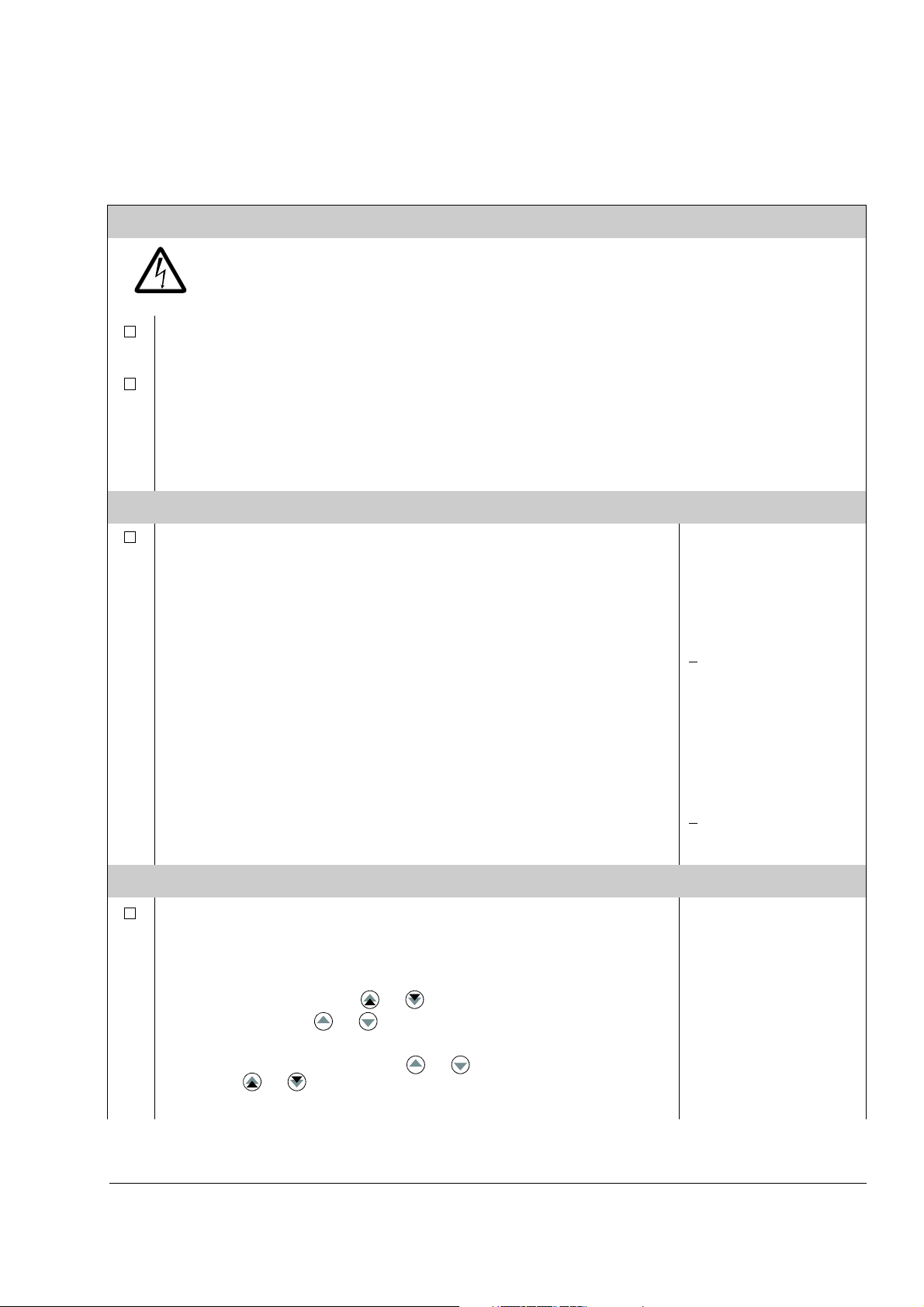
SAFETY
The start-up may only be carried out by a qualified electrician.
The safety instructions must be followed during the start-up procedure. See the
appropriate hardware manual for safety instructions.
Check the installation. See the installation checklist in the appropriate hardware/installation
manual.
Check that the starting of the motor does not cause any danger.
De-couple the driven machine if:
- there is a risk of damage in case of incorrect direction of rotation, or
- a Standard ID Run needs to be performed during the drive start-up. (ID Run is essential only
in applications which require the ultimate in motor control accuracy.)
Start-up and control through the I/O
Page 16

16
POWER-UP
Apply the main power. The control panel first shows the panel
identification data …
… then the Identification Display of the drive …
… then the Actual Signal Display …
…after which the display suggests starting the Language Selection.
(If no key is pressed for a few seconds, the display starts to alternate between the
Actual Signal Display and the suggestion on selecting the language.)
The drive is now ready for the start-up.
SELECTING THE LANGUAGE
Press the FUNC key.
Scroll to the desired language by the arrow keys ( or ) and
press ENTER to accept.
(The drive loads the selected language into use, shifts back to the Actual Signal
Display and starts to alternate between the Actual Signal Display and the
suggestion on starting the guided motor set-up.)
CDP312 PANEL Vx.xx
.......
ACS800
ID NUMBER 1
1 -> 0.0 rpm O
FREQ 0.00 Hz
CURRENT 0.00 A
POWER 0.00 %
1 -> 0.0 rpm O
*** INFORMATION ***
Press FUNC to start
Language Selection
Language Selection 1/1
LANGUAGE ?
[ENGLISH]
ENTER:OK ACT:EXIT
1 -> 0.0 rpm O
*** INFORMATION ***
Press FUNC to start
guided Motor Setup
STARTING THE GUIDED MOTOR SET-UP
Press FUNC to start the guided motor set-up.
(The display shows which general command keys to use when stepping through
the assistant.)
Press ENTER to step forward.
Follow the instructions given on the display.
Motor Setup 1/10
ENTER: Ok/Continue
ACT: Exit
FUNC: More Info
Motor Setup 2/10
MOTOR NAMEPLATE DATA
AVAILABLE?
ENTER:Yes FUNC:Info
Start-up and control through the I/O
Page 17
How to perform the limited start-up (covers only the basic settings)
Before you start, ensure you have the motor nameplate data at your hand.
SAFETY
The start-up may only be carried out by a qualified electrician.
The safety instructions must be followed during the start-up procedure. See the
appropriate hardware manual for safety instructions.
Check the installation. See the installation checklist in the appropriate hardware/installation
manual.
Check that the starting of the motor does not cause any danger.
De-couple the driven machine if:
- there is a risk of damage in case of incorrect direction of rotation, or
- a Standard ID Run needs to be performed during the drive start-up. (ID Run is essential
only in applications which require the ultimate in motor control accuracy.)
POWER-UP
17
Apply the main power. The control panel first shows the panel
identification data …
… then the Identification Display of the drive …
… then the Actual Signal Display …
…after which the display suggests starting the Language Selection.
(If no key is pressed for a few seconds, the display starts to alternate between the
Actual Signal Display and the suggestion on starting the Language Selection.)
Press ACT to remove the suggestion on starting the language
selection.
The drive is now ready for the limited start-up.
MANUAL START-UP DATA ENTERING (parameter group 99)
Select the language. The general parameter setting procedure is
described below.
The general parameter setting procedure:
- Press PAR to select the Parameter Mode of the panel.
- Press the double-arrow keys ( or ) to scroll the parameter groups.
- Press the arrow keys ( or ) to scroll parameters within a group.
- Activate the setting of a new value by ENTER.
- Change the value by the arrow keys ( or ), fast change by the doublearrow keys ( or ).
- Press ENTER to accept the new value (brackets disappear).
CDP312 PANEL Vx.xx
.......
ACS800
ID NUMBER 1
1 -> 0.0 rpm O
REQ 0.00 Hz
F
CURRENT 0.00 A
POWER 0.00 %
1 -> 0.0 rpm O
*** INFORMATION ***
Press FUNC to start
Language Selection
1 -> 0.0 rpm O
FREQ 0.00 Hz
CURRENT 0.00 A
POWER 0.00 %
1 -> 0.0 rpm O
99 START-UP DATA
01 LANGUAGE
ENGLISH
1 -> 0.0 rpm O
99 START-UP DATA
01 LANGUAGE
[ENGLISH]
Start-up and control through the I/O
Page 18
18
M2AA 200 MLA 4
1475
1475
1470
1470
1475
1770
32.5
56
34
59
54
59
0.83
0.83
0.83
0.83
0.83
0.83
3GAA 202 001 - ADA
180
IEC 34-1
6210/C36312/C3
Cat. no
35
30
30
30
30
30
50
50
50
50
50
60
690 Y
400 D
660 Y
380 D
415 D
440 D
V
Hz kW
r/min A
cos
IA/IN
t
E/s
Ins.cl. F
IP 55
No
IEC 200 M/L 55
3
motor
ABB Motors
380 V
input
voltage
Select the Application Macro. The general parameter setting
procedure is given above.
The default value FACTORY is suitable in most cases.
Select the motor control mode. The general parameter setting
procedure is given above.
DTC is suitable in most cases. The SCALAR control mode is recommended
- for multimotor drives when the number of the motors connected to the drive is
variable
- when the nominal current of the motor is less than 1/6 of the nominal current of
the inverter
- when the inverter is used for test purposes with no motor connected.
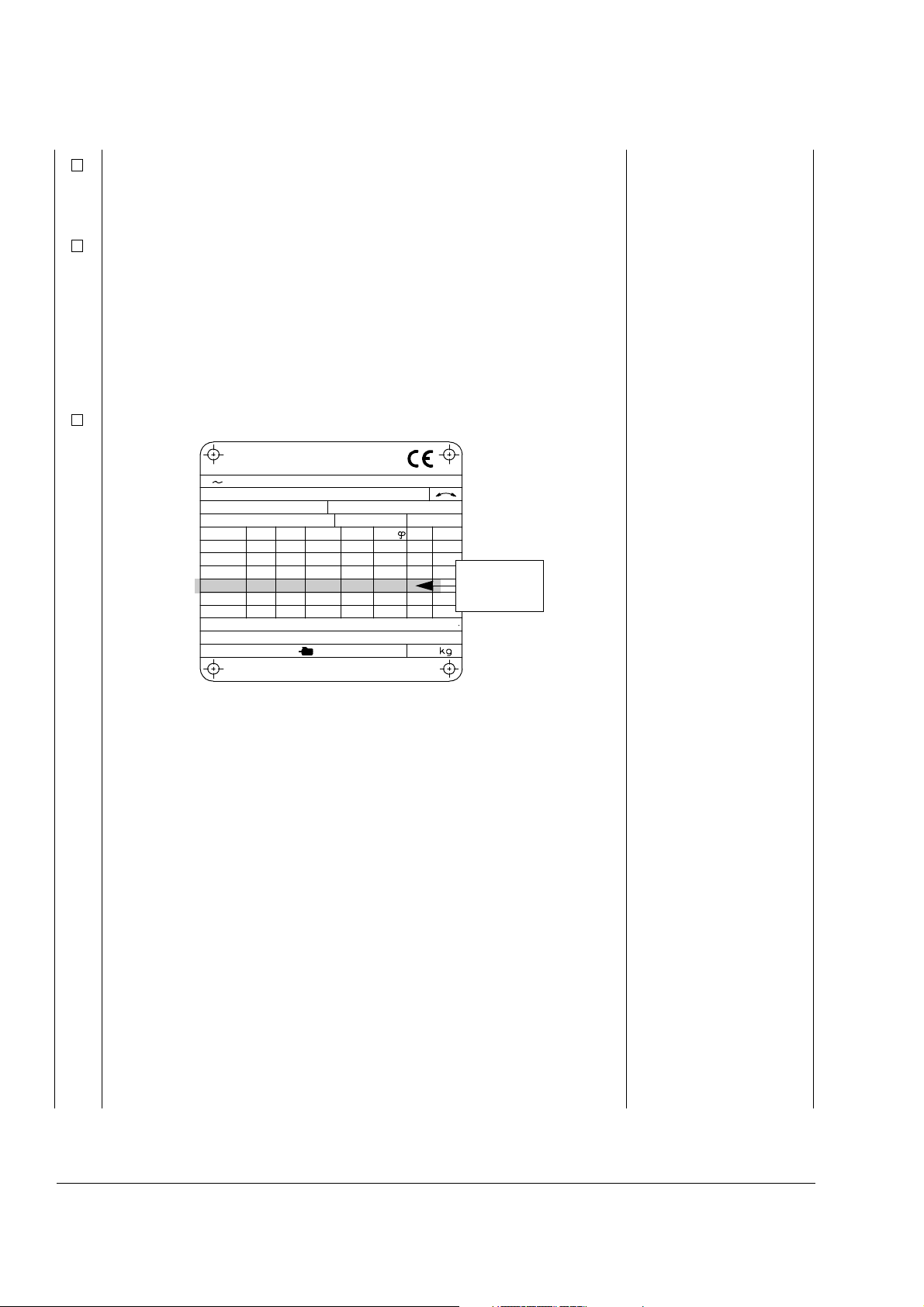
Enter the motor data from the motor nameplate:
1 -> 0.0 rpm O
99 START-UP DATA
02 APPLICATION MACRO
[ ]
1 -> 0.0 rpm O
99 START-UP DATA
04 MOTOR CTRL MODE
[DTC]
Note: Set the motor data to
exactly the same value as
on the motor nameplate.
For example, if the motor
nominal speed is 1440 rpm
on the nameplate, setting
the value of parameter
99.08 MOTOR NOM
SPEED to 1500 rpm
results in the wrong
operation of the drive.
- motor nominal voltage
Allowed range: 1/2 · U
each of the nominal voltage ranges: 415 VAC for 400 VAC units, 500 VAC for 500
VAC units and 690 VAC for 600 VAC units.)
- motor nominal current
Allowed range: approx. 1/6 · I
99.04 = SCALAR))
- motor nominal frequency
Range: 8 … 300 Hz
- motor nominal speed
Range: 1 …18000 rpm
-motor nominal power
Range: 0 …9000 kW
Start-up and control through the I/O
N
… 2 · U
2hd
of ACS800. (UN refers to the highest voltage in
N
… 2 · I
of ACS800 (0 … 2 · I
2hd
if parameter
2hd
1 -> 0.0 rpm O
99 START-UP DATA
05 MOTOR NOM VOLTAGE
[ ]
1 -> 0.0 rpm O
99 START-UP DATA
06 MOTOR NOM CURRENT
[ ]
1 -> 0.0 rpm O
99 START-UP DATA
07 MOTOR NOM FREQ
[ ]
1 -> 0.0 rpm O
99 START-UP DATA
08 MOTOR NOM SPEED
[ ]
1 -> 0.0 rpm O
99 START-UP DATA
09 MOTOR NOM POWER
[ ]
Page 19

19
When the motor data has been entered, two displays (warning and
information) start to alternate. Move to next step without pressing
any key.
1 -> 0.0 rpm O
ACS800
** WARNING **
ID MAGN REQ
Note: If you select STANDARD ID Run, the brake is opened when
the Start command is given from the control panel and the brake
remains open until the STANDARD ID Run is completed. If you
select ID MAGN, the brake is kept closed during the ID Run
sequence.
1 -> 0.0 rpm I
*** Information ***
Press green button
to start ID MAGN
Select the motor identification method.
The default value ID MAGN (ID Magnetisation) is suitable for most applications. It is applied
in this basic start-up procedure. If your selection is ID Magnetisation, move to next step
without pressing any key.
The ID Run (STANDARD or REDUCED) should be selected if:
- The operation point is near zero speed constantly, and/or
- Operation at torque range above the motor nominal torque within a wide speed range and
without any measured speed feedback is required.
If your selection is ID Run, continue by following the separate instructions given a few pages
ahead in section How to perform the ID Run on page 22.
IDENTIFICATION MAGNETISATION (with Motor ID Run selection ID MAGN)
Press the LOC/REM key to change to local control (L shown on the
first row).
Press to start the Identification Magnetisation. The motor is
magnetised at zero speed for 20 to 60 s. Three warnings are
displayed:
The first warning is displayed when the magnetisation starts.
The second warning is displayed while the magnetisation is on.
The third warning is displayed after the magnetisation is completed.
1 L -> 1242.0 rpm I
** WARNING **
MOTOR STARTS
1 L-> 0.0 rpm I
** WARNING **
ID MAGN
1 L-> 0.0 rpm O
** WARNING **
ID DONE
Start-up and control through the I/O
Page 20
20
forward
direction
reverse
direction
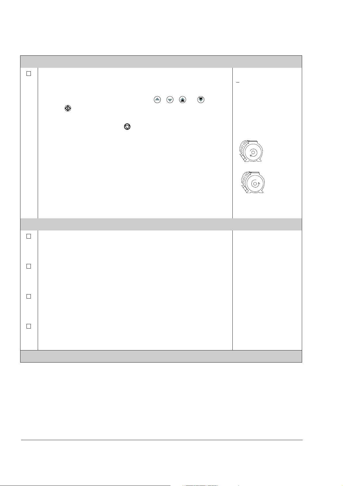
DIRECTION OF ROTATION OF THE MOTOR
Check the direction of rotation of the motor.
- Press ACT to get the status row visible.
- Increase the speed reference from zero to a small value by
pressing REF and then the arrow keys ( , , or ).
- Press to start the motor.
- Check that the motor is running in the desired direction.
- Stop the motor by pressing .
To change the direction of rotation of the motor:
- Disconnect the main power from the drive, and wait 5 minutes for
the intermediate circuit capacitors to discharge. Measure the
voltage between each input terminal (U1, V1 and W1) and earth
with a multimeter to ensure that the frequency converter is
discharged.
- Exchange the position of two motor cable phase conductors at the
motor terminals or at the motor connection box.
- Verify your work by applying the main power and repeating the
check as described above.
SPEED LIMITS AND ACCELERATION/DECELERATION TIMES
Set the minimum speed.
1 L->[xxx] rpm I
FREQ xxx Hz
CURRENT xx A
POWER xx %
1 L-> 0.0 rpm O
20 LIMITS
01 MINIMUM SPEED
[ ]
Set the maximum speed.
Set the acceleration time 1.
Note: Check also acceleration time 2, if two acceleration times will
be used in the application.
Set the deceleration time 1.
Note: Set also deceleration time 2, if two deceleration times will be
used in the application.
The drive is now ready for use.
1 L-> 0.0 rpm O
20 LIMITS
02 MAXIMUM SPEED
[ ]
1 L-> 0.0 rpm O
22 ACCEL/DECEL
02 ACCELER TIME 1
[ ]
1 L-> 0.0 rpm O
22 ACCEL/DECEL
03 DECELER TIME 1
[ ]
Start-up and control through the I/O
Page 21

How to control the drive through the I/O interface
The table below instructs how to operate the drive through the digital and analogue
inputs, when:
• the motor start-up is performed, and
• the default (factory) parameter settings are valid.
PRELIMINARY SETTINGS
21
Ensure the Factory macro is active.
If you need to change the direction of rotation, change the setting of
parameter 10.03 to REQUEST.
Ensure the control connections are wired according to the connection
diagram given for the Factory macro.
Ensure the drive is in external control mode. Press the LOC/REM key to
change between external and local control.
STARTING AND CONTROLLING THE SPEED OF THE MOTOR
Start by switching digital input DI1 on.
Regulate the speed by adjusting the voltage of analogue input AI1.
CHANGING THE DIRECTION OF ROTATION OF THE MOTOR
Forward direction: Switch digital input DI2 off.
See parameter 99.02.
See chapter Application
macros.
In External control, there is
no L visible on the first row
of the panel display.
1 -> 0.0 rpm I
REQ 0.00 Hz
F
CURRENT 0.00 A
POWER 0.00 %
1 -> 500.0 rpm I
FREQ 16.66 Hz
CURRENT 12.66 A
POWER 8.33 %
1 -> 500.0 rpm I
FREQ 16.66 Hz
CURRENT 12.66 A
POWER 8.33 %
Reverse direction: Switch digital input DI2 on.
STOPPING THE MOTOR
Switch off digital input DI1.
1 <- 500.0 rpm I
REQ 16.66 Hz
F
CURRENT 12.66 A
POWER 8.33 %
1 -> 500.0 rpm O
REQ 0.00 Hz
F
CURRENT 0.00 A
POWER 0.00 %
Start-up and control through the I/O
Page 22

22
99 START-UP DATA
10 MOTOR ID RUN
[STANDARD]
1 L ->1242.0 rpm O
1 L ->1242.0 rpm O
ACS800
**WARNING**
ID RUN SEL
How to perform the ID Run
The drive performs the ID Magnetisation automatically at the first start. In most
applications there is no need to perform a separate ID Run. The ID Run (Standard or
Reduced) should be selected if:
• The operation point is near zero speed, and/or
• Operation at torque range above the motor nominal torque within a wide speed
range and without any measured speed feedback is required.
The Reduced ID Run is to be performed instead of the Standard if it is not possible to
disengage the driven machine from the motor.
Note: If you select STANDARD ID Run, the brake is opened when the Start
command is given from the control panel and the brake remains open until the
STANDARD ID Run is completed. If you select ID MAGN, the brake is kept closed
during the ID Run sequence.
ID Run Procedure
Note: If parameter values (Group 10 to 98) are changed before the ID Run, check
that the new settings meet the following conditions:
• 20.01 MINIMUM SPEED <
0 rpm
• 20.02 MAXIMUM SPEED > 80% of motor rated speed
• 20.03 MAXIMUM CURRENT >
100% · I
hd
• 20.04 MAXIMUM TORQUE > 50%
• Ensure that the panel is in the local control mode (L displayed on the status row).
Press the LOC/REM key to switch between modes.
• Change the ID Run selection to STANDARD or REDUCED.
•Press ENTER to verify selection. The following message will be displayed:
Start-up and control through the I/O
Page 23

23
• To start the ID Run, press the key. The Start Interlock (digital input DI_IL) and
Run Enable signals (parameter 16.01 RUN ENABLE) must be active.
Warning when the ID Run is
started
1 L -> 1242.0 rpm I
ACS800
**WARNING**
MOTOR STARTS
In general it is recommended not to press any control panel keys during the ID run.
However:
• The Motor ID Run can be stopped at any time by pressing the control panel stop
key ( ).
• After the ID Run is started with the start key ( ), it is possible to monitor the
actual values by first pressing the ACT key and then a double-arrow key ( ).
Warning during the ID Run Warning after a successfully
completed ID Run
1 L -> 1242.0 rpm I
ACS800
**WARNING**
ID RUN
1 L -> 1242.0 rpm I
ACS800
**WARNING**
ID DONE
Start-up and control through the I/O
Page 24

24
Start-up and control through the I/O
Page 25
Control panel
1 L -> 1242.0 rpm I
F
REQ 45.00 Hz
CURRENT 80.00 A
POWER 75.00 %
ACT PA R FU NC DR IV E
ENTER
LOC RESET REF
REM
I0
1367
5 24
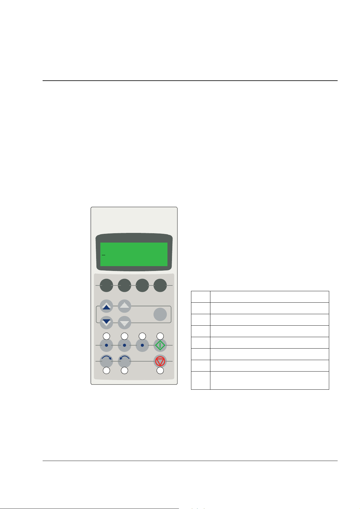
The LCD type display has 4 lines of 20 characters.
The language is selected at start-up (parameter 99.01).
The control panel has four operation modes:
- Actual Signal Display Mode (ACT key)
- Parameter Mode (PAR key)
- Function Mode (FUNC key)
- Drive Selection Mode (DRIVE key)
The use of single arrow keys, double arrow keys and
ENTER depend on the operation mode of the panel.
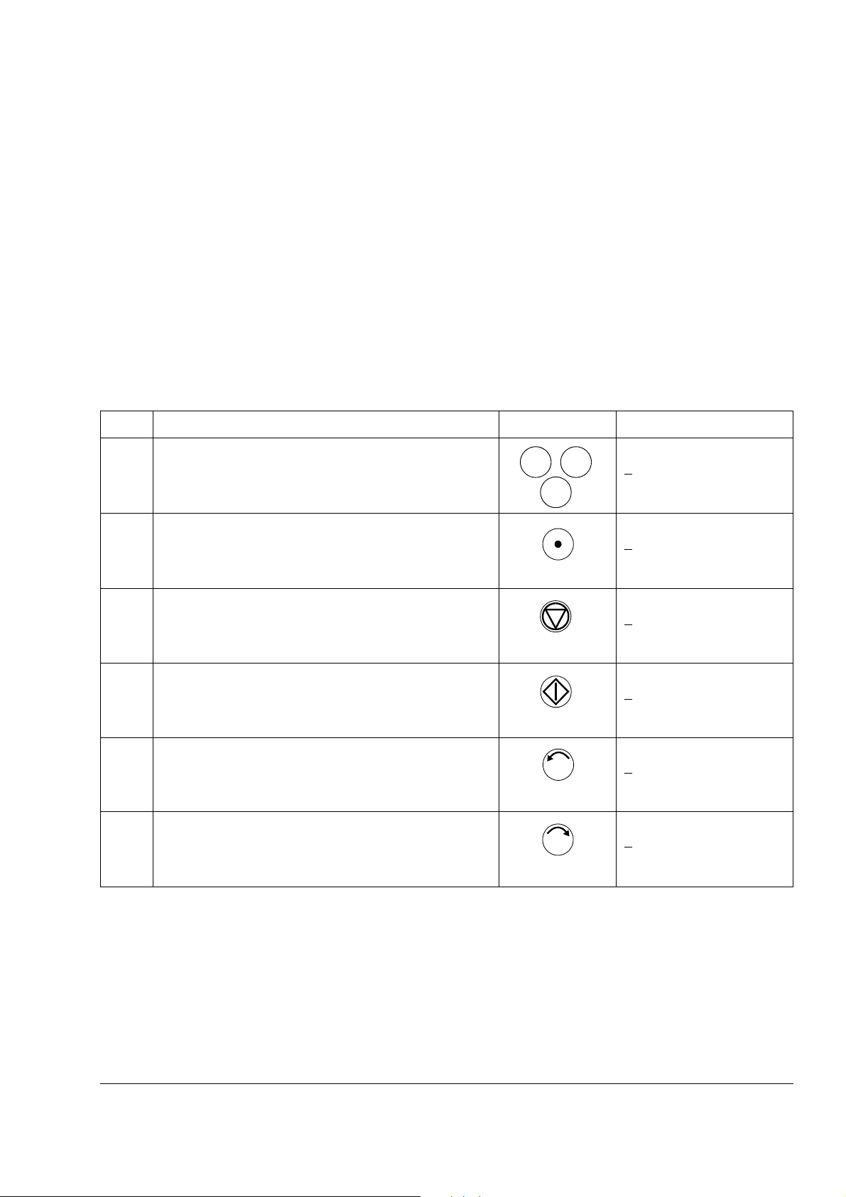
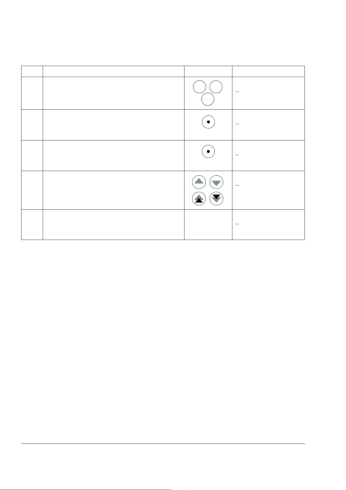
The drive control keys are:
No. Use
1Start
2Stop
3 Activate reference setting
4 Forward direction of rotation
5 Reverse direction of rotation
6 Fault reset
7 Change between Local / Remote (external)
control
Chapter overview
The chapter describes how to use the control panel CDP 312R.
The same control panel is used with all ACS800 series drives, so the instructions
given apply to all ACS800 types. The display examples shown are based on the
Standard Control Program; displays produced by other application programs may
differ slightly.
Overview of the panel
25
Control panel
Page 26
26
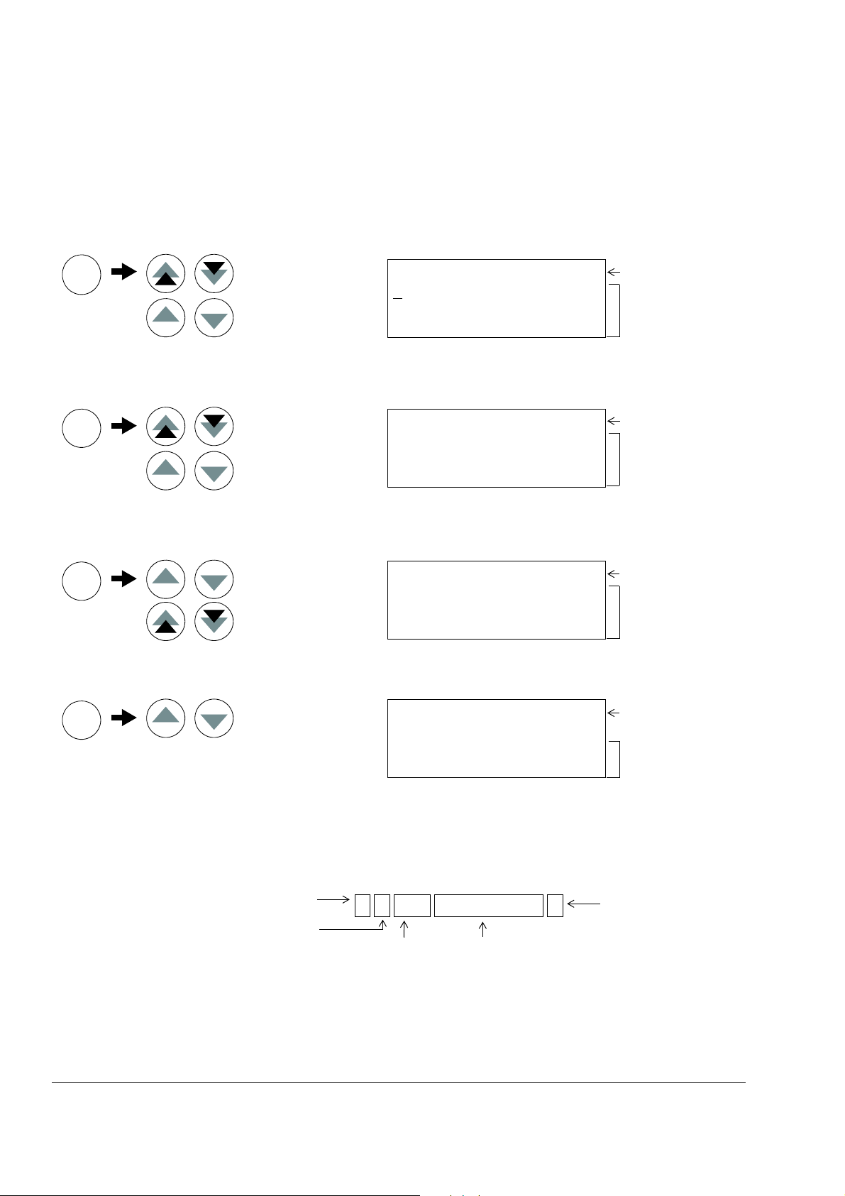
Parameter Mode
Function Mode
Drive Selection Mode
Act. signal / Fault history
Enter selection mode
Accept new signal
Group selection
Parameter selection
Enter change mode
Accept new value
Fast value change
Slow value change
Function start
Drive selection
Enter change mode
Accept new value
Actual Signal Display Mode
ENTER
ENTER
ENTER
ENTER
selection
ID number change
Status row
Status row
ACT
PAR
FUNC
DRIVE
1 L -> 1242.0 rpm O
F
REQ 45.00 Hz
CURRENT 80.00 A
POWER 75.00 %
1 L -> 1242.0 rpm O
10 START/STOP/DIR
01 EXT1 STRT/STP/DIR
DI1,2
1 L -> 1242.0 rpm O
Motor Setup
Application Macro
Speed Control EXT1
ACS800
ASXR7260 xxxxxx
ID NUMBER 1
Act. signal / Fault message
scrolling
Actual signal names
and values
Parameter group
Parameter
Parameter value
Status row
List of functions
Device type
SW loading package
name and ID number
Row selection
Page selection
Drive ID number
Drive control status
L = Local control
R = Remote control
“ “ = External control
Drive status
I = Running
O = Stopped
“ “ = Run disabled
1 L -> 1242.0 rpm I
Direction of rotation
-> = Forward
<- = Reverse
Drive reference
Panel operation mode keys and displays
The figure below shows the mode selection keys of the panel, and the basic
operations and displays in each mode.
Status row
The figure below describes the status row digits.
Control panel
Page 27
Drive control with the panel
ACT PA R
FUNC
LOC
REM
0
I
The user can control the drive with the panel as follows:
• start, stop, and change direction of the motor
• give the motor speed reference or torque reference
• give a process reference (when the process PID control is active)
• reset the fault and warning messages
• change between local and external drive control.
The panel can be used for control of the drive control always when the drive is under
local control and the status row is visible on the display.
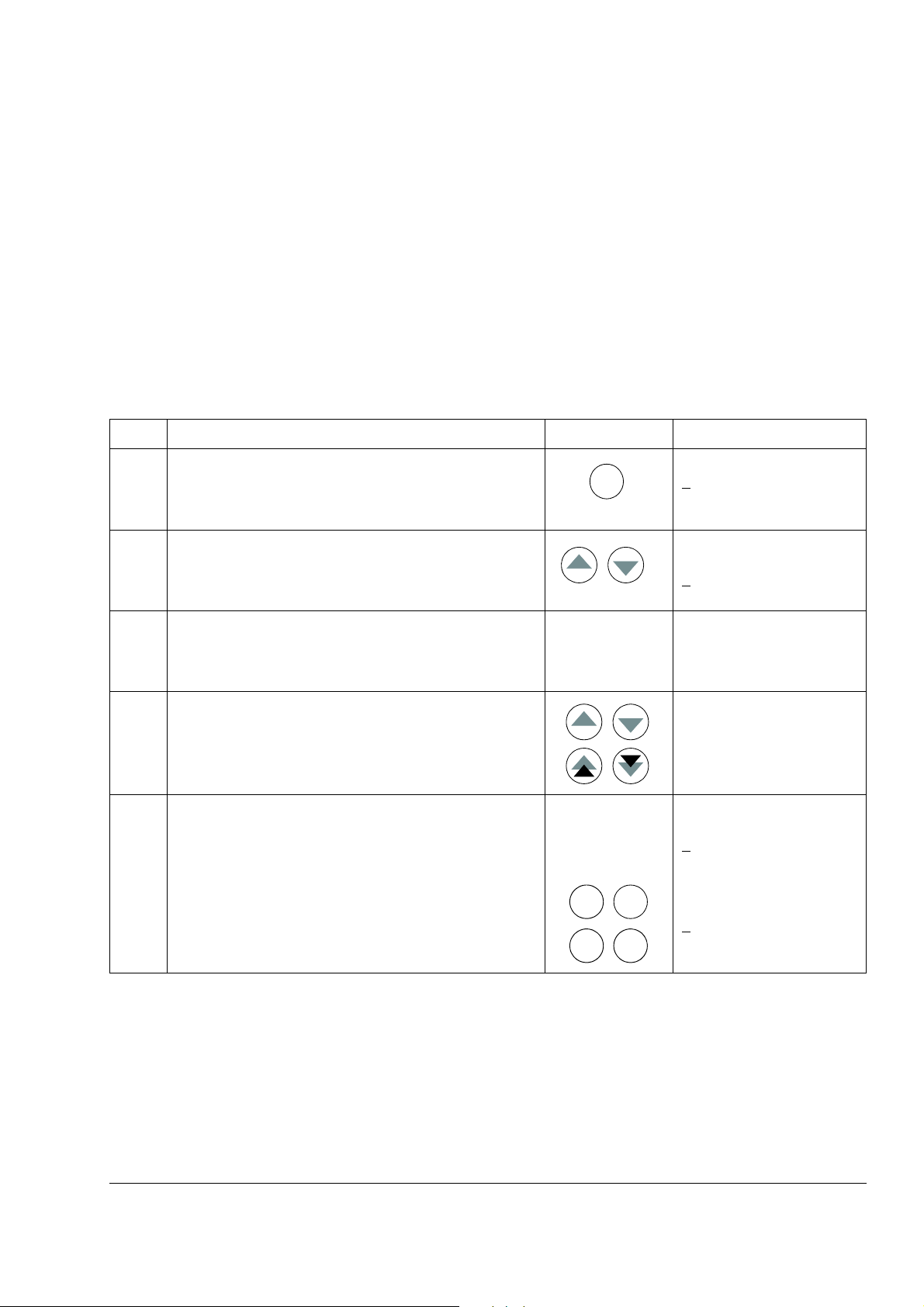
How to start, stop and change direction
Step Action Press Key Display
1. To show the status row. 1 ->1242.0 rpm I
REQ 45.00 Hz
F
CURRENT 80.00 A
POWER 75.00 %
27
2. To switch to local control.
(only if the drive is not under local control, i.e. there is no L
on the first row of the display.)
3. To stop 1 L ->1242.0 rpm O
4. To start 1 L ->1242.0 rpm I
5. To change the direction to reverse. 1 L <-1242.0 rpm I
6. To change the direction to forward. 1 L ->1242.0 rpm I
1 L ->1242.0 rpm I
REQ 45.00 Hz
F
CURRENT 80.00 A
POWER 75.00 %
REQ 45.00 Hz
F
CURRENT 80.00 A
POWER 75.00 %
FREQ 45.00 Hz
CURRENT 80.00 A
POWER 75.00 %
REQ 45.00 Hz
F
CURRENT 80.00 A
POWER 75.00 %
FREQ 45.00 Hz
CURRENT 80.00 A
POWER 75.00 %
Control panel
Page 28
28
ACT PAR
FUNC
LOC
REM
REF
ENTER
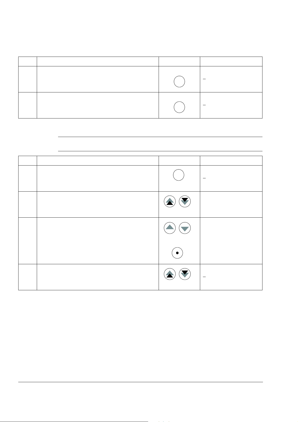
How to set speed reference
Step Action Press Key Display
1. To show the status row. 1 ->1242.0 rpm I
F
REQ 45.00 Hz
CURRENT 80.00 A
POWER 75.00 %
2. To switch to local control.
(Only if the drive is not under local control, i.e. there is no L
on the first row of the display.)
1 L ->1242.0 rpm I
REQ 45.00 Hz
F
CURRENT 80.00 A
POWER 75.00 %
3. To enter the Reference Setting function. 1 L ->[1242.0 rpm]I
REQ 45.00 Hz
F
CURRENT 80.00 A
POWER 75.00 %
4. To change the reference.
(slow change)
1 L ->[1325.0 rpm]I
F
REQ 45.00 Hz
CURRENT 80.00 A
POWER 75.00 %
(fast change)
5. To save the reference.
(The value is stored in the permanent memory; it is
restored automatically after power switch-off.)
1 L -> 1325.0 rpm I
REQ 45.00 Hz
F
CURRENT 80.00 A
POWER 75.00 %
Control panel
Page 29
Actual signal display mode
ACT
ENTER
ENTER
ACT
FUNC DRIVE
PAR
In the Actual Signal Display Mode, the user can:
• show three actual signals on the display at a time
• select the actual signals to display
• view the fault history
• reset the fault history.
The panel enters the Actual Signal Display Mode when the user presses the ACT
key, or if he does not press any key within one minute.
How to select actual signals to the display
Step Action Press key Display
1. To enter the Actual Signal Display Mode. 1 L -> 1242.0 rpm I
F
REQ 45.00 Hz
CURRENT 80.00 A
POWER 75.00 %
29
2. To select a row (a blinking cursor indicates the selected
row).
3. To enter the actual signal selection function. 1 L -> 1242.0 rpm I
4. To select an actual signal.
To change the actual signal group.
5.a To accept the selection and to return to the Actual Signal
Display Mode.
5.b To cancel the selection and keep the original selection.
The selected keypad mode is entered.
1 L -> 1242.0 rpm I
FREQ 45.00 Hz
URRENT 80.00 A
C
POWER 75.00 %
1 ACTUAL SIGNALS
04 CURRENT
80.00 A
1 L -> 1242.0 rpm I
1 ACTUAL SIGNALS
05 TORQUE 70.00 %
1 L -> 1242.0 rpm I
FREQ 45.00 Hz
ORQUE 70.00 %
T
POWER 75.00 %
1 L -> 1242.0 rpm I
FREQ 45.00 Hz
C
URRENT 80.00 A
POWER 75.00 %
Control panel
Page 30
30
ACT
ACT
ACT
RESET
How to display the full name of the actual signals
Step Action Press key Display
1. To display the full name of the three actual signals. Hold 1 L -> 1242.0 rpm I
F
REQUENCY
CURRENT
POWER
2. To return to the Actual Signal Display Mode. Release 1 L -> 1242.0 rpm I
FREQ 45.00 Hz
CURRENT 80.00 A
POWER 75.00 %
How to view and reset the fault history
Note: The fault history cannot be reset if there are active faults or warnings.
Step Action Press key Display
1. To enter the Actual Signal Display Mode. 1 L -> 1242.0 rpm I
REQ 45.00 Hz
F
CURRENT 80.00 A
POWER 75.00 %
2. To enter the Fault History Display. 1 L -> 1242.0 rpm I
1 LAST FAULT
+OVERCURRENT
6451 H 21 MIN 23 S
3. To select the previous (UP) or the next fault/warning
(DOWN).
1 L -> 1242.0 rpm I
2 LAST FAULT
+OVERVOLTAGE
1121 H 1 MIN 23 S
To clear the Fault History. 1 L -> 1242.0 rpm I
2 LAST FAULT
H MIN S
4. To return to the Actual Signal Display Mode. 1 L -> 1242.0 rpm I
REQ 45.00 Hz
F
CURRENT 80.00 A
POWER 75.00 %
Control panel
Page 31

How to display and reset an active fault
ACT
RESET
1 L -> 1242.0 rpm I
2 LAST FAULT
+DC OVERVOLT (3210)
1121 H 1 MIN 23 S
Event Information on display
Drive detects a fault and
generates a fault message
Sequential number of the event and
LAST FAULT text.
Name of the fault and a “+” sign in front
of the name.
Total power-on time.
User resets the fault message. Sequential number of the event and
LAST FAULT text.
-RESET FAULT text.
Total power-on time.
Drive generates a warning
message.
Sequential number of the event and
LAST WARNING text.
Name of the warning and a “+” sign in
front of the name.
Total power-on time.
Drive deactivates the warning
message.
Sequential number of the event and
LAST WARNING text.
Name of the warning and a “-” sign in
front of the name.
Total power-on time.
Sequential number
(1 is the most recent event)
Sign
Power-
on time
Name and
code
A Fault History View
WARNING! If an external source for start command is selected and it is ON, the
drive will start immediately after fault reset. If the cause of the fault has not been
removed, the drive will trip again.
Step Action Press Key Display
1. To display an active fault. 1 L -> 1242.0 rpm
ACS800
** FAULT **
ACS800 TEMP
2. To reset the fault. 1 L -> 1242.0 rpm O
REQ 45.00 Hz
F
CURRENT 80.00 A
POWER 75.00 %
About the fault history
The fault history restores information on the latest events (faults, warnings and
resets) of the drive. The table below shows how the events are stored in the fault
history.
31
Control panel
Page 32

32
PAR
ENTER
ENTER
ACT
FUNC DRIVE
PAR
Parameter mode
In the Parameter Mode, the user can:
• view the parameter values
• change the parameter settings.
The panel enters the Parameter Mode when the user presses the PAR key.
How to select a parameter and change the value
Step Action Press key Display
1. To enter the Parameter Mode. 1 L -> 1242.0 rpm O
10 START/STOP/DIR
01 EXT1 STRT/STP/DIR
DI1,2
2. To select a group. 1 L -> 1242.0 rpm O
11 REFERENCE SELECT
01 KEYPAD REF SEL
REF1 (rpm)
3. To select a parameter within a group. 1 L -> 1242.0 rpm O
11 REFERENCE SELECT
03 EXT REF1 SELECT
AI1
4. To enter the parameter setting function. 1 L -> 1242.0 rpm O
11 REFERENCE SELECT
03 EXT REF1 SELECT
[AI1]
5. To change the parameter value.
- (slow change for numbers and text)
- (fast change for numbers only)
6a. To save the new value. 1 L -> 1242.0 rpm O
6b. To cancel the new setting and keep the original value,
press any of the mode selection keys.
The selected mode is entered.
1 L -> 1242.0 rpm O
11 REFERENCE SELECT
03 EXT REF1 SELECT
[AI2]
11 REFERENCE SELECT
03 EXT REF1 SELECT
AI2
1 L -> 1242.0 rpm O
11 REFERENCE SELECT
03 EXT REF1 SELECT
AI1
Control panel
Page 33

How to adjust a source selection (pointer) parameter
PAR
ENTER
ENTER
1 L ->1242.0 rpm O
84 ADAPTIVE PROGRAM
06 INPUT1
[±001.018.00]
Inversion field
Group field
Index field
Bit field
Inversion field inverts the selected parameter
value. Plus sign (+): no inversion, minus (-) sign:
inversion.
Bit field selects the bit number (relevant only if the
parameter value is a packed boolean word).
Index field selects the parameter index.
Group field selects the parameter group.
Most parameters define values that are used directly in the drive application
program. Source selection (pointer) parameters are exceptions: They point to the
value of another parameter. The parameter setting procedure differs somewhat from
that of the other parameters.
Step Action Press Key Display
33
1. See the table above to
- enter the Parameter Mode
- select the correct parameter group and parameter
- enter the parameter setting mode
2. To scroll between the inversion, group, index and bit
3. To adjust the value of a field. 1 L ->1242.0 rpm O
4. To accept the value.
fields.
1)
1)
1 L ->1242.0 rpm O
84 ADAPTIVE PROGRAM
06 INPUT1
[±000.000.00]
1 L ->1242.0 rpm O
84 ADAPTIVE PROGRAM
06 INPUT1
[±000.000
84 ADAPTIVE PROGRAM
06 INPUT1
[±000.018
.00]
.00]
Note: Instead of pointing to another parameter, it is also possible to define a
constant by the source selection parameter. Proceed as follows:
- Change the inversion field to C. The appearance of the row changes. The rest of
the line is now a constant setting field.
- Give the constant value to the constant setting field.
- Press Enter to accept.
Control panel
Page 34

34
1)
The parameter groups 98, 99 and the results of the motor identification are not included by default. The restriction
prevents downloading of unfit motor data. In special cases it is, however, possible to download all. For more information,
please contact your local ABB representative.
Function mode
In the Function Mode, the user can:
• start a guided procedure for adjusting the drive settings (assistants)
• upload the drive parameter values and motor data from the drive to the panel.
• download group 1 to 97 parameter values from the panel to the drive.
• adjust the contrast of the display.
The panel enters the Function Mode when the user presses the FUNC key.
1)
Control panel
Page 35

How to enter an assistant, browse and exit
FUNC
ENTER
ENTER
ENTER
)(
FUNC, ACT
FUNC
ENTER
RESET
The table below shows the operation of the basic keys which lead the user through
an assistant. The Motor Setup task of the Start-up Assistant is used as an example.
The Start-up Assistant is not available in Scalar mode or when the parameter lock is
on. (99.04 MOTOR CTRL MODE = SCALAR or 16.02 PARAMETER LOCK =
LOCKED or 16.10 ASSIST SEL = OFF)
Step Action Press Key Display
1. To enter the Function Mode. 1 L -> 1242.0 rpm O
otor Setup
M
Application Macro
Speed Control EXT1
35
2. To select a task or function from the list (a flashing cursor
indicates the selection).
Double arrows: To change page to see more assistants/
functions.
3. To enter the task. Motor Setup 1/10
4. To accept and continue. Motor Setup 2/10
5. To accept and continue. Motor Setup 3/10
6. a. To adjust the requested drive parameter. Motor Setup 3/10
b. To ask for information on the requested value.
(To scroll the information displays
and return to the task).
1 L -> 1242.0 rpm O
M
otor Setup
Application Macro
Speed Control EXT 1
ENTER: Ok/Continue
ACT: Exit
FUNC: More Info
MOTOR NAMEPLATE DATA
AVAILABLE?
ENTER:Yes FUNC:Info
MOTOR NOM VOLTAGE?
[0 V]
ENTER:Ok RESET:Back
MOTOR NOM VOLTAGE?
[415 V]
ENTER:Ok RESET:back
INFO P99.05
Set as given on the
motor nameplate.
7. a. To accept a value and step forward. Motor Setup 4/10
MOTOR NOM CURRENT?
[0.0 A]
ENTER:Ok RESET:Back
b. To cancel the setting and take one step back. Motor Setup 3/10
MOTOR NOM VOLTAGE?
[415 V]
ENTER:Ok RESET:back
Control panel
Page 36

36
2 x ACT
FUNC
ENTER
LOC
REM
Step Action Press Key Display
8. To cancel and exit.
Note: 1 x ACT returns to the first display of the task.
How to upload data from a drive to the panel
Note:
• Upload before downloading.
• Ensure the firmware of the destination drive is the same (e.g. standard firmware).
• Before removing the panel from a drive, ensure the panel is in remote operating
mode (change with the LOC/REM key).
• Stop the drive before downloading.
Before upload, repeat the following steps in each drive:
• Setup the motors.
• Activate the communication to the optional equipment. (See parameter group 98
OPTION MODULES.)
Before upload, do the following in the drive from which the copies are to be taken:
1 L -> 0.0 rpm O
FREQ 0.00 Hz
CURRENT 0.00 A
POWER 0.00 %
• Set the parameters in groups 10 to 97 as preferred.
• Proceed to the upload sequence (below).
Step Action Press Key Display
1. Enter the Function Mode. 1 L -> 1242.0 rpm O
otor Setup
M
Application Macro
Speed Control EXT1
2. Enter the page that contains the upload, download and
contrast functions.
3. Select the upload function (a flashing cursor indicates the
selected function).
4. Enter the upload function. 1 L -> 1242.0 rpm O
5. Switch to external control.
(No L on the first row of the display.)
1 L -> 1242.0 rpm O
PLOAD <=<=
U
DOWNLOAD =>=>
CONTRAST 4
1 L -> 1242.0 rpm O
U
PLOAD <=<=
DOWNLOAD =>=>
CONTRAST 4
UPLOAD <=<=
1 -> 1242.0 rpm O
PLOAD <=<=
U
DOWNLOAD =>=>
CONTRAST 4
Control panel
Page 37

Step Action Press Key Display
LOC
REM
FUNC
ENTER
6. Disconnect the panel and reconnect it to the drive into
which the data will be downloaded.
How to download data from the panel to a drive
Consider the notes in section How to upload data from a drive to the panel on page
36.
Step Action Press Key Display
1. Connect the panel containing the uploaded data to the
drive.
37
2. Ensure the drive is in local control (L shown on the first row
of the display). If necessary, press the LOC/REM key to
change to local control.
1 L -> 1242.0 rpm I
F
REQ 45.00 Hz
CURRENT 80.00 A
POWER 75.00 %
3. Enter the Function Mode. 1 L -> 1242.0 rpm O
otor Setup
M
Application Macro
Speed Control EXT1
4. Enter the page that contains the upload, download and
contrast functions.
1 L -> 1242.0 rpm O
UPLOAD <=<=
DOWNLOAD =>=>
CONTRAST 4
5. Select the download function (a flashing cursor indicates
the selected function).
1 L -> 1242.0 rpm O
UPLOAD <=<=
DOWNLOAD =>=>
CONTRAST 4
6. Start the download. 1 L -> 1242.0 rpm O
DOWNLOAD =>=>
Control panel
Page 38

38
FUNC
ENTER
ENTER
ACT
FUNC
DRIVE
PAR
How to set the contrast of the display
Step Action Press Key Display
1. Enter the Function Mode. 1 L -> 1242.0 rpm O
Motor Setup
Application Macro
Speed Control EXT1
2. Enter the page that contains the upload, download and
contrast functions.
1 L -> 1242.0 rpm O
PLOAD <=<=
U
DOWNLOAD =>=>
CONTRAST 4
3. Select a function (a flashing cursor indicates the selected
function).
1 L -> 1242.0 rpm O
UPLOAD <=<=
DOWNLOAD =>=>
ONTRAST 4
C
4. Enter the contrast setting function. 1 L -> 1242.0 rpm O
CONTRAST [4]
5. Adjust the contrast. 1 L -> 1242.0 rpm
CONTRAST [6]
6.a Accept the selected value. 1 L -> 1242.0 rpm O
UPLOAD <=<=
DOWNLOAD =>=>
CONTRAST 6
6.b Cancel the new setting and retain the original value by
pressing any of the mode selection keys.
1 L -> 1242.0 rpm I
FREQ 45.00 Hz
CURRENT 80.00 A
The selected mode is entered.
POWER 75.00 %
Control panel
Page 39

Drive selection mode
DRIVE
1o
o
PAR
FUNC
ACT
In normal use the features available in the Drive Selection Mode are not needed; the
features are reserved for applications where several drives are connected to one
panel link. (For more information, see the Installation and Start-up Guide for the
Panel Bus Connection Interface Module, NBCI, [3AFY58919748 (English)].
In the Drive Selection Mode, the user can:
• Select the drive with which the panel communicates through the panel link.
• Change the identification number of a drive connected to the panel link.
• View the status of the drives connected on the panel link.
The panel enters the Drive Selection Mode when the user presses the DRIVE key.
Each on-line station must have an individual identification number (ID). By default,
the ID number of the drive is 1.
Note: The default ID number setting of the drive should not be changed unless the
drive is to be connected to the panel link with other drives on-line.
39
How to select a drive and change its panel link ID number
Step Action Press key
1. To enter the Drive Selection Mode. ACS800
ASAAA5000 xxxxxx
ID NUMBER 1
2. To select the next drive/view.
The ID number of the station is changed by first pressing
ENTER (the brackets round the ID number appear) and
then adjusting the value with arrow buttons. The new value
is accepted with ENTER. The power of the drive must be
switched off to validate its new ID number setting.
The status display of all devices connected to the Panel
Link is shown after the last individual station. If all stations
do not fit on the display at once, press the double-arrow up
to view the rest of them.
3. To connect to the last displayed drive and to enter another
mode, press one of the mode selection keys.
The selected mode is entered.
ACS800
ASAAA5000 xxxxxx
ID NUMBER 1
Status Display Symbols:
= Drive stopped, direction
forward
= Drive running, direction
reverse
F = Drive tripped on a fault
1 L -> 1242.0 rpm I
F
REQ 45.00 Hz
CURRENT 80.00 A
POWER 75.00 %
Display
Control panel
Page 40

40
Boolean 0000 0000 0001 1010
Hex 0 0 1 A
Bit 15 Bit 0
Reading and entering packed boolean values on the display
Some actual values and parameters are packed boolean, i.e. each individual bit has
a defined meaning (explained at the corresponding signal or parameter). On the
control panel, packed boolean values are read and entered in hexadecimal format.
In this example, bits 1, 3 and 4 of the packed boolean value are ON:
Control panel
Page 41

Program features
Chapter overview
The chapter describes program features. For each feature, there is a list of related
user settings, actual signals, and fault and warning messages.
Start-up Assistant
Introduction
The assistant guides the user through the start-up procedure, helping the user to
feed the requested data (parameter values) to the drive. The assistant also check
that the entered values are valid, i.e. within the allowed range. At the first start, the
drive suggests entering the first task of the assistant, Language Select,
automatically.
The Start-up Assistant is divided into tasks. The user may activate the tasks either
one after the other as the Start-up Assistant suggests, or independently. The user
may also adjust the drive parameters in the conventional way without using the
assistant at all.
41
See chapter Control panel on how to start the assistant, browse and exit.
The default order of the tasks
Depending on the selection made in the Application task (parameter 99.02), the
Start-up Assistant decide which consequent tasks it suggests. The default tasks are
shown in the table below.
Application
Selection
FACTORY, SEQ
CTRL
HAND/AUTO Language Select, Motor Set-up, Application, Option Modules, Speed Control EXT2, Start/Stop
T CTRL Language Select, Motor Set-up, Application, Option Modules, Torque Control, Start/Stop Control,
PID CTRL Language Select, Motor Set-up, Application, Option Modules, PID Control, Start/Stop Control, Speed
Default Tasks
Language Select, Motor Set-up, Application, Option Modules, Speed Control EXT1, Start/Stop
Control, Protections, Output Signals
Control, Speed Control 1, Protections, Output Signals
Speed Control EXT1, Protections, Output Signals
Control EXT1, Protections, Output Signals
Program features
Page 42

42
List of tasks and the relevant drive parameters
Name Description Set parameters
Language Select Selecting the language 99.01
Motor Set-up Setting the motor data
Performing the motor identification. (If the speed limits are not in
the allowed range: Setting the limits).
Application Selecting the application macro 99.02, parameters associated to
Option Modules Activating the option modules Group 98, 35, 52
Speed Control
EXT1
Speed Control
EXT2
Tor q ue Cont r ol Selecting the source for the torque reference 11.06
PID Control Selecting the source for the process reference 11.06
Start/Stop Control Selecting the source for start and stop signals of the two external
Protections Setting the torque and current limits 20.03, 20.04
Output Signals Selecting the signals indicated through the relay outputs RO1,
Selecting the source for the speed reference 11.03
(If AI1 is used: Setting analogue input AI1 limits, scale,
inversion)
Setting the reference limits 11.04, 11.05
Setting the speed (frequency) limits 20.02, 20.01, (20.08, 20.07)
Setting acceleration and deceleration times 22.02, 22.03
(Setting up the brake chopper if activated by parameter 27.01) (Group 27, 20.05, 14.01)
(If 99.02 is not SEQ CTRL: Setting constant speeds) (Group 12)
Setting the source for the speed reference 11.06
(If AI1 is used: Setting analogue input AI1 limits, scale,
inversion)
Setting the reference limits 11.08, 11.07
(If AI1 is used: Setting analogue input AI1 limits, scale,
inversion)
Setting the reference limits 11.08, 11.07
Setting the torque ramp up and ramp down times 24.01, 24.02
(If AI1 is used: Setting analogue input AI1 limits, scale,
inversion)
Setting the reference limits 11.08, 11.07
Setting the speed (reference) limits 20.02, 20.01 (20.08, 20.07)
Setting the source and limits for the process actual value 40.07, 40.09, 40.10
control locations, EXT1 and EXT2
Selecting between EXT1 and EXT2 11.02
Defining the direction control 10.03
Defining the start and stop modes 21.01, 21.02, 21.03
Selecting the use of Run Enable signal 16.01, 21.07
Setting the ramp time for the Run Enable function 22.07
RO2, RO3 and optional RO’s (if installed)
Selecting the signals indicated through the analogue output
AO1, AO2 and optional AO’s (if installed). Setting the minimum,
maximum, scaling and inversion.
99.05, 99.06, 99.09, 99.07, 99.08,
99.04
99.10 (20.8, 20.07)
the macro
(13.01, 13.02, 13.03, 13.04,
13.05, 30.01)
(13.01, 13.02, 13.03, 13.04,
13.05, 30.01)
(13.01, 13.02, 13.03, 13.04,
13.05, 30.01)
(13.01, 13.02, 13.03, 13.04,
13.05, 30.01)
10.01, 10.02
Group 14
15.01, 15.02, 15.03, 15.04, 15.05,
(Group 96)
Program features
Page 43

Contents of the assistant displays
Main Display Information Display
1
2
3
4
Motor Setup 3/10
MOTOR NOM VOLTAGE?
[0 V]
ENTER:Ok RESET:Back
INFO P99.05
Set as given on the motor
nameplate.
1 Name of the assistant, step
number / total number of steps
Text INFO, index of parameter to
be set
2 Request/question Help text …
3 Feed-in field … help text continued
4 Commands: accept value and
step forward or cancel and step
backwards
double arrow symbol (indicates
that the text continues)
Slot 1
CH0
(DDCS)
Fieldbus
ACS800
RDCO
module
Control panel
DriveWindow
External controlLocal control
Standard I/O
Slot 1 or Slot 2
RTAC/RDIO/RAIO
adapter
module
CH3
(DDCS)
Fieldbus adapter
Nxxx
or
Advant controller
(e.g. AC 80, AC 800M)
CH1
(DDCS)
RTAC/RDIO/RAIO
AIMA-01 I/O
adapter module
module
There are two types of displays in the Start-up Assistant: The main displays and the
information displays. The main displays prompt the user to feed in information or
answer a question. The assistant steps through the main displays. The information
displays contain help texts for the main displays. The figure below shows a typical
example of both and explanations of the contents.
43
Local control vs. external control
The drive can receive start, stop and direction commands and reference values from
the control panel or through digital and analogue inputs. An optional fieldbus adapter
enables control over an open fieldbus link. A PC equipped with DriveWindow can
also control the drive.
Program features
Page 44

44
1 L ->1242 rpm I
External Control through the Input/
Output terminals, or through the
fieldbus interfaces
1 R ->1242 rpm I 1 ->1242 rpm I
External Control by control panel
Local control
The control commands are given from the control panel keypad when the drive is in
local control. L indicates local control on the panel display.
The control panel always overrides the external control signal sources when used in
local mode.
External control
When the drive is in external control, the commands are given through the standard
I/O terminals (digital and analogue inputs), optional I/O extension modules and/or
the fieldbus interface. In addition, it is also possible to set the control panel as the
source for the external control.
External control is indicated by a blank on the panel display or with an R in those
special cases when the panel is defined as a source for external control.
The user can connect the control signals to two external control locations, EXT1 or
EXT2. Depending on the user selection, either one is active at a time. This function
operates on a 12 ms time level.
Settings
Panel key Additional information
LOC/REM Selection between local and external control
Parameter
11. 02 Selection between EXT1 and EXT2
10.01 Start, stop, direction source for EXT1
11. 03 Reference source for EXT1
10.02 Start, stop, direction source for EXT2
11. 06 Reference source for EXT2
Group 98 OPTION
MODULES
Activation of the optional I/O and serial communication
Diagnostics
Actual signals Additional information
01.11, 01.12 EXT1 reference, EXT2 reference
03.02 EXT1/EXT2 selection bit in a packed boolean word
Program features
Page 45

Block diagram: start, stop, direction source for EXT1
DI1 / Std IO
Fb. selection
See chapter
Fieldbus control.
Fieldbus adapter slot 1
KEYPAD
EXT1
DI6 / Std IO
DI1 / DIO ext 1
DI2 / DIO ext 1
DI1 / DIO ext 2
DI2 / DIO ext 2
I/O Extensions
See group 98
OPTION
MODULES.
DI7 to DI9
COMM.
CW
DI1
DI6
Control panel
Start/stop/
DI1 / Std IO = Digital input DI1 on the standard I/O terminal block
DI1 / DIO ext 1 = Digital input DI1 on the digital I/O extension module 1
direction
10.01
Select
CH0 / RDCO board
Standard Modbus® Link
EXT1
AI1 / Std IO
AI1 / AIO ext
AI2 / AIO ext
11.0 3
Select
DI1 / DIO ext 3
DI2 / DIO ext 3
KEYPAD
COMM.
REF
Control panel
I/O Extensions
See parameter
group 98 OPTION
MODULES.
AI2 / Std IO
AI3 / Std IO
DI3 / Std IO
DI4 / Std IO
AI1, AI2, AI3, DI3, DI4
Fb. selection
See chapter
Fieldbus control.
AI5, AI6
DI11, DI12
REF1 (rpm)
Reference
AI1 / Std IO = Analogue input AI1 on the standard I/O terminal block
AI1 / AIO ext = Analogue input AI1 on the analogue I/O extension module
Fieldbus adapter slot 1
CH0 / RDCO board
Standard Modbus Link
The figure below shows the parameters that select the interface for start, stop, and
direction for external control location EXT1.
45
Block diagram: reference source for EXT1
The figure below shows the parameters that select the interface for the speed
reference of external control location EXT1.
Program features
Page 46

46
Reference types and processing
The drive can accept a variety of references in addition to the conventional analogue
input signal and control panel signals.
• The drive reference can be given with two digital inputs: One digital input
increases the speed, the other decreases it.
• The drive accepts a bipolar analogue speed reference. This feature allows both
the speed and direction to be controlled with a single analogue input. The
minimum signal is full speed reversed and the maximum signal is full speed
forward.
• The drive can form a reference out of two analogue input signals by using
mathematical functions: Addition, subtraction, multiplication, minimum selection,
and maximum selection.
• The drive can form a reference out of an analogue input signal and a signal
received through a serial communication interface by using mathematical
functions: addition and multiplication.
It is possible to scale the external reference so that the signal minimum and
maximum values correspond to a speed other than the minimum and maximum
speed limits.
Settings
Parameter Additional information
Group 11 REFERENCE
SELECT
Group 20 LIMITS Operating limits
Group 22 ACCEL/DECEL Speed reference acceleration and deceleration ramps
Group 24 TORQUE CTRL Torque reference ramp times
Group 32 SUPERVISION Reference supervision
External reference source, type and scaling
Diagnostics
Actual signal Additional information
01.11, 01.12 Values of external references
Group 02 ACTUAL SIGNALS The reference values in different stages of the reference processing
chain.
Parameter
Group 14 RELAY OUTPUTS Active reference / reference loss through a relay output
Group 15 ANALOGUE
OUTPUTS
Reference value
Program features
Page 47

Reference trimming
40.14
Select
%ref
1
Mul.
Mul.
Add
%ref= The drive reference before trimming
%ref’ = The drive reference after trimming
max. speed= Par. 20.02 (or 20.01 if the absolute value is greater)
max. freq = Par. 20.08 (or 20.07 if the absolute value is greater)
max. torq = Par. 20.14 (or 20.13 if the absolute value is greater)
%ref
%ref’
DIRECT (3)
PROPOR. (2)
OFF (1)
max.speed
Switch
max.freq
99.04 (DTC)
40.17
PID
tref
k
ti
td
i
dFiltT
errVInv
rInt
oh1
ol1
Actual Values
40.05
40.07
AI1
AI2
AI3
AI5
AI6
IMOT
40.19
Filter
40.15
Select
AI1
AI2
...
40.16
40.01
40.02
40.03
40.04
40.05
40.13
PIDmax
PIDmin
.
.
.
40.18
Select
max.torque
In reference trimming, the external %-reference (External reference REF2) is
corrected depending on the measured value of a secondary application variable.
The block diagram below illustrates the function.
47
Settings
Parameter Additional information
40.14…40.18 Trimming function settings
40.01…40.13, 40.19 PID control block settings
Group 20 LIMITS Drive operation limits
Program features
Page 48

48
Drive rollers (pull)
Tension measurement
Speed controlled conveyor line
PID
Add
Tension
measurement
Speed reference
Tension
setpoint
Trimmed
speed reference
Simplified block diagram
Example
The drive runs a conveyor line. It is speed-controlled but the line tension also needs
to be taken into account: If the measured tension exceeds the tension setpoint, the
speed will be slightly decreased, and vice versa.
To accomplish the desired speed correction, the user:
• activates the trimming function and connects the tension setpoint and the
measured tension to it
• tunes the trimming to a suitable level.
Program features
Page 49

Programmable analogue inputs
The drive has three programmable analogue inputs: one voltage input (0/2 to 10 V or
-10 to 10 V) and two current inputs (0/4 to 20 mA). Two extra inputs are available if
an optional analogue I/O extension module is used. Each input can be inverted and
filtered, and the maximum and minimum values can be adjusted.
Update cycles in the Standard Control Program
Input Cycle
AI / standard 6 ms
AI / extension 6 ms (100 ms
1)
Update cycle in the motor temperature measurement function. See group 35 MOT TEMP MEAS.
Settings
Parameter Additional information
Group 11 REFERENCE
SELECT
Group 13 ANALOGUE
INPUTS
30.01 Supervision of AI loss
Group 40 PID
CONTROL
35.01 AI in a motor temperature measurement
40.15 AI in a drive reference trimming
42.07 AI in a mechanical brake control function
98.06 Activation of optional analogue inputs
98.13 Optional AI signal type definition (bipolar or unipolar)
98.14 Optional AI signal type definition (bipolar or unipolar)
AI as a reference source
Processing of the standard inputs
AI as a PID process control reference or actual values
49
1)
)
Diagnostics
Actual value Additional information
01.18, 01.19, 01.20 Values of standard inputs
01.38, 01.39 Value of optional inputs
Group 09 ACTUAL
SIGNALS
Scaled analogue input values (integer values for function block
programming)
Program features
Page 50

50
Programmable analogue outputs
Two programmable current outputs (0/4 to 20 mA) are available as standard, and
two outputs can be added by using an optional analogue I/O extension module.
Analogue output signals can be inverted and filtered.
The analogue output signals can be proportional to motor speed, process speed
(scaled motor speed), output frequency, output current, motor torque, motor power,
etc.
It is possible to write a value to an analogue output through a serial communication
link.
Update cycles in the Standard Control Program
Output Cycle
AO / standard 24 ms
AO / extension 24 ms (1000 ms
1)
Update cycle in the motor temperature measurement function. See group 35 MOT TEMP MEAS.
Settings
1)
)
Parameter Additional information
Group 15 ANALOGUE
OUTPUTS
30.20 Operation of an externally controlled AO in a communication break
30.22 Supervision of the use of optional AO
Group 35 MOT TEMP
MEAS
Group 96 EXTERNAL AOOptional AO value selection and processing
Group 98 OPTION
MODULES
AO value selection and processing (standard outputs)
AO in motor temperature measurement
Activation of optional I/O
Diagnostics
Actual value Additional information
01.22, 01.23 Values of the standard outputs
01.28, 01.29 Values of the optional outputs
Warning
IO CONFIG (FF8B) Improper use of optional I/O
Program features
Page 51

Programmable digital inputs
The drive has six programmable digital inputs as a standard. Six extra inputs are
available if optional digital I/O extension modules are used.
Update cycles in the Standard Control Program
Input Cycle
DI / standard 6 ms
DI / extension 12 ms
Settings
Parameter Additional information
Group 10 START/STOP/
DIR
Group 11 REFERENCE
SELECT
Group 12 CONSTANT
SPEEDS
Group 16 SYST CTRL
INPUTS
22.01 DI as acceleration and deceleration ramp selection signal
30.03 DI as external fault source
30.05 DI in motor overtemperature supervision function
30.22 Supervision of optional I/O use
40.20 DI as sleep function activation signal (in PID process control)
42.02 DI as mechanical brake acknowledgement signal
98.03…96.05 Activation of the optional digital I/O extension modules
98.09…98.11 Naming of the optional digital inputs in the application program
51
DI as start, stop, direction
DI in reference selection, or reference source
DI in constant speed selection
DI as external Run Enable, fault reset or user macro change signal
Diagnostics
Actual value Additional information
01.17 Values of the standard digital inputs
01.40 Values of the optional digital inputs
Warning
IO CONFIG (FF8B) Improper use of optional I/O
Fault
I/O COMM ERR (7000) Communication loss to I/O
Program features
Page 52

52
Programmable relay outputs
As standard there are three programmable relay outputs. Six outputs can be added
by using the optional digital I/O extension modules. By means of a parameter setting
it is possible to choose which information to indicate through the relay output: ready,
running, fault, warning, motor stall, etc.
It is possible to write a value to a relay output through a serial communication link.
Update cycles in the Standard Control Program
Output Cycle
RO / standard 100 ms
RO / extension 100 ms
Settings
Parameter Additional information
Group 14 RELAY
OUTPUTS
30.20 Operation of an externally controlled relay output on a communication break
Group 42 BRAKE
CONTROL
Group 98 OPTION
MODULES
RO value selections and operation times
RO in a mechanical brake control
Activation of optional relay outputs
Diagnostics
Actual value Additional information
01.21 Standard relay output states
01.41 Optional relays output states
Program features
Page 53

Actual signals
Several actual signals are available:
• Drive output frequency, current, voltage and power
• Motor speed and torque
• Supply voltage and intermediate circuit DC voltage
• Active control location (Local, EXT1 or EXT2)
• Reference values
• Drive temperature
• Operating time counter (h), kWh counter
• Digital I/O and Analogue I/O status
• PID controller actual values (if the PID Control macro is selected)
Three signals can be shown simultaneously on the control panel display. It is also
possible to read the values through the serial communication link or through the
analogue outputs.
53
Settings
Parameter Additional information
Group 15 ANALOGUE
OUTPUTS
Group 92 D SET TR
ADDR
Diagnostics
Actual value Additional information
Group 01 ACTUAL
SIGNALS … 09
ACTUAL SIGNALS
Motor identification
The performance of Direct Torque Control is based on an accurate motor model
determined during the motor start-up.
A motor Identification Magnetisation is automatically done the first time the start
command is given. During this first start-up, the motor is magnetised at zero speed
for several seconds to allow the motor model to be created. This identification
method is suitable for most applications.
Selection of an actual signal to an analogue output
Selection of an actual signal to a data set (serial communication)
Lists of actual signals
In demanding applications a separate Identification Run can be performed.
Settings
Parameter 99.10.
Program features
Page 54

54
130
260
390
520
1.6 4.8 8 11.2 14.4
t(s)
U
DC
f
out
T
M
UDC= Intermediate circuit voltage of the drive, f
out
= output frequency of the drive,
TM = Motor torque
Loss of supply voltage at nominal load (f
out
= 40 Hz). The intermediate circuit DC voltage drops to the
minimum limit. The controller keeps the voltage steady as long as the supply voltage is switched off.
The drive runs the motor in generator mode. The motor speed falls but the drive is operational as long
as the motor has enough kinetic energy.
U
in
20
40
60
80
40
80
120
160
T
M
(Nm)
f
out
(Hz)
U
DC
(V d.c.)
Power loss ride-through
If the incoming supply voltage is cut off, the drive will continue to operate by utilising
the kinetic energy of the rotating motor. The drive will be fully operational as long as
the motor rotates and generates energy to the drive. The drive can continue the
operation after the break if the main contactor remained closed.
Note: Cabinet assembled units equipped with main contactor option have a “hold
circuit” that keeps the contactor control circuit closed during a short supply break.
The allowed duration of the break is adjustable. The factory setting is five seconds.
Automatic Start
Since the drive can detect the state of the motor within a few milliseconds, the
starting is immediate under all conditions. There is no restart delay. E.g. the starting
of turbining pumps or windmilling fans is easy.
Settings
Parameter 21.01.
Program features
Page 55

DC Magnetising
DC hold
t
Motor
DC Hold
speed
DC hold
speed
t
Speed
Reference
Speed
Flux Braking
No Flux Braking
t (s)
Motor
Flux Braking
No Flux Braking
f (Hz)
T
Br
T
N
20
40
60
(%)
T
N
= 100 Nm
T
Br
= Braking Torque
Speed
50 HZ / 60 Hz
When DC Magnetising is activated, the drive automatically magnetises the motor
before starting. This feature guarantees the highest possible breakaway torque, up
to 200% of motor nominal torque. By adjusting the premagnetising time, it is possible
to synchronise the motor start and e.g. a mechanical brake release. The Automatic
Start feature and DC Magnetising cannot be activated at the same time.
Settings
Parameters 21.01 and 21.02.
DC Hold
By activating the motor DC Hold feature it is possible to
lock the rotor at zero speed. When both the reference
and the motor speed fall below the preset DC hold
speed, the drive stops the motor and starts to inject DC
into the motor. When the reference speed again exceeds
the DC hold speed, the normal drive operation resumes.
55
Settings
Flux Braking
Parameters 21.04, 21.05, and 21.06.
The drive can provide greater deceleration by raising the level of magnetisation in
the motor. By increasing the motor flux, the energy generated by the motor during
braking can be converted to motor thermal energy. This feature is useful in motor
power ranges below 15 kW.
Program features
Page 56

56
120
80
40
0
5 1020304050
1
2
3
4
5
120
80
40
0
5 1020304050
1
2
3
4
5
f (Hz)
Braking Torque (%)
f (Hz)
Flux Braking
No Flux Braking
1
2
3
4
5
2.2 kW
15 kW
37 kW
75 kW
250 kW
Rated Motor Power
The drive monitors the motor status continuously, also during the Flux Braking.
Therefore, Flux Braking can be used both for stopping the motor and for changing
the speed. The other benefits of Flux Braking are:
• The braking starts immediately after a stop command is given. The function does
not need to wait for the flux reduction before it can start the braking.
• The cooling of the motor is efficient. The stator current of the motor increases
during the Flux Braking, not the rotor current. The stator cools much more
efficiently than the rotor.
Settings
Parameter 26.02.
Flux Optimisation
Flux Optimisation reduces the total energy consumption and motor noise level when
the drive operates below the nominal load. The total efficiency (motor and the drive)
can be improved by 1% to 10%, depending on the load torque and speed.
Settings
Parameter 26.01.
Program features
Page 57

Acceleration and deceleration ramps
Linear
t (s)
Motor
2
speed
S-curve
Two user-selectable acceleration and deceleration ramps are available. It is possible
to adjust the acceleration/deceleration times and the ramp shape. Switching
between the two ramps can be controlled via a digital input.
The available ramp shape alternatives are Linear
and S-curve.
Linear: Suitable for drives requiring steady or slow
acceleration/deceleration.
S-curve: Ideal for conveyors carrying fragile loads,
or other applications where a smooth transition is
required when changing the speed.
Settings
Parameter group 22 ACCEL/DECEL.
Critical speeds
57
A Critical Speeds function is available for applications where it is necessary to avoid
certain motor speeds or speed bands because of e.g. mechanical resonance
problems.
Settings
Parameter group 25 CRITICAL SPEEDS.
Constant speeds
It is possible to predefine 15 constant speeds. Constant speeds are selected with
digital inputs. Constant speed activation overrides the external speed reference.
This function operates on a 6 ms time level.
Settings
Parameter group 12 CONSTANT SPEEDS.
Program features
Page 58

58
A: Undercompensated
B: Normally tuned (autotuning)
C: Normally tuned (manually). Better dynamic performance than with B
D: Overcompensated speed controller
%
t
n
C
B
D
n
N
A
Derivative
Proportional,
integral
Derivative
acceleration
compensation
To rq u e
reference
Speed
reference
Actual speed
Error
value
-
+
+
+
+
Speed controller tuning
During the motor identification, the speed controller is automatically tuned. It is,
however, possible to manually adjust the controller gain, integration time and
derivation time, or let the drive perform a separate speed controller Autotune Run. In
Autotune Run, the speed controller is tuned based on the load and inertia of the
motor and the machine. The figure below shows speed responses at a speed
reference step (typically, 1 to 20%).
Program features
The figure below is a simplified block diagram of the speed controller. The controller
output is the reference for the torque controller.
Settings
Parameter group 23 SPEED CTRL and 20 LIMITS.
Diagnostics
Actual signal 01.02.
Page 59

Speed control performance figures
100
t (s)
T
T
N
(%)
T
load
n
act-nref
n
N
0.1 - 0.4 %sec
TN = rated motor torque
nN = rated motor speed
n
act
= actual speed
n
ref
= speed reference
*Dynamic speed error depends on speed controller tuning.
Speed Control No Pulse
Encoder
With Pulse
Encoder
Static speed error,
% of n
N
+ 0.1 to 0.5%
(10% of nominal
slip)
+ 0.01%
Dynamic speed
error
0.4 %sec.* 0.1 %sec.*
*When operated around zero frequency, the error may be
greater.
Torque Control No Pulse
Encoder
With Pulse
Encoder
Linearity error +
4%* + 3%
Repeatability
error
+
3%* + 1%
Torque rise time 1 to 5 ms 1 to 5 ms
100
t(s)
T
T
N
< 5 ms
90
10
(%)
T
ref
T
act
TN = rated motor torque
T
ref
= torque reference
T
act
= actual torque
The table below shows typical performance figures for speed control when Direct
Torque Control is used.
Torque control performance figures
59
The drive can perform precise torque control without any speed feedback from the
motor shaft. The table below shows typical performance figures for torque control,
when Direct Torque Control is used.
Program features
Page 60

60
f (Hz)
Motor Voltage
No compensation
IR Compensation
Scalar control
It is possible to select Scalar Control as the motor control method instead of Direct
Torque Control (DTC). In the Scalar Control mode, the drive is controlled with a
frequency reference. The outstanding performance of the default motor control
method, Direct Torque Control, is not achieved in Scalar Control.
It is recommended to activate the Scalar Control mode in the following special
applications:
• In multimotor drives: 1) if the load is not equally shared between the motors, 2) if
• If the nominal current of the motor is less than 1/6 of the nominal output current of
• If the drive is used without a motor connected (e.g. for test purposes)
• The drive runs a medium voltage motor via a step-up transformer.
In the Scalar Control mode, some standard features are not available.
Settings
the motors are of different sizes, or 3) if the motors are going to be changed after
the motor identification
the drive
Parameter 99.04.
IR compensation for a scalar controlled drive
IR Compensation is active only when the motor
control mode is Scalar (see section Scalar control
on page 60). When IR Compensation is
activated, the drive gives an extra voltage boost
to the motor at low speeds. IR Compensation is
useful in applications that require high breakaway
torque. In Direct Torque Control, no IR
Compensation is possible/needed.
Settings
Parameter 26.03.
Program features
Page 61

Hexagonal motor flux
Typically the drive controls the motor flux in such a way that the rotating flux vector
follows a circular pattern. This is ideal in most applications. When operated above
the field weakening point (FWP, typically 50 or 60 Hz), it is, however, not possible to
reach 100% of the output voltage. The peak load capacity of the drive is lower than
with the full voltage.
If hexagonal flux control is selected, the motor flux is controlled along a circular
pattern below the field weakening point, and along a hexagonal pattern in the field
weakening range. The applied pattern is changed gradually as the frequency
increases from 100% to 120% of the FWP. Using the hexagonal flux pattern, the
maximum output voltage can be reached; The peak load capacity is higher than with
the circular flux pattern but the continuous load capacity is lower in the frequency
range of FWP to 1.6
Settings
Parameter 26.05.
· FWP, due to increased losses.
Programmable protection functions
61
AI<Min
AI<Min function defines the drive operation if an analogue input signal falls below the
preset minimum limit.
Settings
Parameter 30.01.
Panel Loss
Panel Loss function defines the operation of the drive if the control panel selected as
control location for the drive stops communicating.
Settings
Parameter 30.02.
External Fault
External Faults can be supervised by defining one digital input as a source for an
external fault indication signal.
Settings
Parameter 30.03.
Program features
Page 62

62
Motor
100%
Temp.
63%
Motor thermal time
t
t
100%
50
100
150
Zero speed load
Motor load curve
Break point
Motor
Speed
Load
Current
(%)
Rise
Motor Thermal Protection
The motor can be protected against overheating by activating the Motor Thermal
Protection function and by selecting one of the motor thermal protection modes
available.
The Motor Thermal Protection modes are based either on a motor temperature
thermal model or on an overtemperature indication from a motor thermistor.
Motor temperature thermal model
The drive calculates the temperature of the motor on the basis of the following
assumptions:
1) The motor is at the estimated temperature (value of 01.37 MOTOR TEMP EST
saved at power switch off) when power is applied to the drive. When power is
applied for the first time, the motor is at the ambient temperature (30°C).
2) Motor temperature is calculated using either the user-adjustable or automatically
calculated motor thermal time and motor load curve (see the figures below). The
load curve should be adjusted in case the ambient temperature exceeds 30°C.
Use of the motor thermistor
Settings
Program features
It is possible to detect motor overtemperature by connecting a motor thermistor
(PTC) between the +24 VDC voltage supply offered by the drive and digital input
DI6. In normal motor operation temperature, the thermistor resistance should be less
than 1.5 kohm (current 5 mA). The drive stops the motor and gives a fault indication
if the thermistor resistance exceeds 4 kohm
regulations for protecting against contact.
. The installation must meet the
Parameters 30.04 to 30.09.
Note: It is also possible to use the motor temperature measurement function. See
sections Motor temperature measurement through the standard I/O on page 71 and
Motor temperature measurement through an analogue I/O extension on page 73.
Page 63

Stall Protection
The drive protects the motor in a stall situation. It is possible to adjust the supervision
limits (torque, frequency, time) and choose how the drive reacts to a motor stall
condition (warning indication / fault indication & stop the drive / no reaction).
The torque and current limits, which define the stall limit, must be set according to
the maximum load of the used application. Note: Stall limit is restricted by internal
current limit 03.04 TORQ_INV_CUR_LIM.
When the application reaches the stall limit and the output frequency of the drive is
below the stall frequency: Fault is activated after the stall time delay.
Settings
Parameters 30.10 to 30.12.
Parameters 20.03, 20.13 and 20.14 (Define the stall limit.)
Underload Protection
Loss of motor load may indicate a process malfunction. The drive provides an
underload function to protect the machinery and process in such a serious fault
condition. Supervision limits - underload curve and underload time - can be chosen
as well as the action taken by the drive upon the underload condition (warning
indication / fault indication & stop the drive / no reaction).
63
Settings
Parameters 30.13 to 30.15.
Motor Phase Loss
The Phase Loss function monitors the status of the motor cable connection. The
function is useful especially during the motor start: the drive detects if any of the
motor phases is not connected and refuses to start. The Phase Loss function also
supervises the motor connection status during normal operation.
Settings
Parameter 30.16.
Program features
Page 64

64
Earth Fault Protection
The earth fault protection detects earth faults in the motor or motor cable. The
protection is based on sum current measurement.
• An earth fault in the supply cable does not activate the protection.
• In an earthed (grounded) supply, the protection activates in 200 microseconds.
• In an unearthed (ungrounded) supply, the supply capacitance should be
1 microfarad or more.
• The capacitive currents caused by shielded motor cables up to 300 metres do not
activate the protection.
• Earth fault protection is deactivated when the drive is stopped.
Note: With parallel connected inverter modules, the earth fault indication is
CUR UNBAL xx. See chapter Fault tracing.
Settings
Parameter 30.17.
Communication Fault
The Communication Fault function supervises the communication between the drive
and an external control device (e.g. a fieldbus adapter module).
Settings
Parameters 30.18 to 30.21.
Supervision of optional IO
The function supervises the use of the optional analogue and digital inputs and
outputs in the application program, and warns if the communication to the input/
output is not operational.
Settings
Parameter 30.22.
Preprogrammed faults
Overcurrent
The overcurrent trip limit for the drive is 1.65 to 2.17 · I
type.
DC overvoltage
depending on the drive
max
Program features
The DC overvoltage trip limit is 1.3 × 1.35 × U
value of the supply voltage range. For 400 V units, U
U
is 500 V. For 690 V units, U
1max
is 690 V. The actual voltage in the
1max
1max
, where U
is 415 V. For 500 V units,
1max
is the maximum
1max
intermediate circuit corresponding to the supply voltage trip level is 728 V DC for
400 V units, 877 V DC for 500 V units, and 1210 V DC for 690 V units.
Page 65

DC undervoltage
65
The DC undervoltage trip limit is 0.6 × 1.35 × U
value of the supply voltage range. For 400 V and 500 V units, U
690 V units, U
is 525 V. The actual voltage in the intermediate circuit
1min
1min
, where U
is the minimum
1min
is 380 V. For
1min
corresponding to the supply voltage trip level is 307 V DC for 400 V and 500 V units,
and 425 V DC for 690 V units.
Drive temperature
The drive supervises the inverter module temperature. There are two supervision
limits: warning limit and fault trip limit.
Enhanced drive temperature monitoring for ACS800, frame sizes R7 and R8
Traditionally, drive temperature monitoring is based on the power semiconductor
(IGBT) temperature measurement which is compared with a fixed maximum IGBT
temperature limit. However, certain abnormal conditions such as cooling fan failure,
insufficient cooling air flow or excessive ambient temperature might cause
overheating inside the converter module, which the traditional temperature
monitoring alone does not detect. The Enhanced drive temperature monitoring
improves the protection in these situations.
The function monitors the converter module temperature by checking cyclically that
the measured IGBT temperature is not excessive considering the load current,
ambient temperature, and other factors that affect the temperature rise inside the
converter module. The calculation uses an experimentally defined equation that
simulates the normal temperature changes in the module depending on the load.
Drive generates a warning when the temperature exceeds the limit, and trips when
temperature exceeds the limit by 5°C.
Note: The monitoring is available for ACS800-02, -04 and -07, frame sizes R7 and
R8 with Standard Control Program version ASXR7360 (and later versions). For
ACS800-U2, -U4 and -U7, frame sizes R7 and R8, the monitoring is available with
Standard Control Program version ASXR730U (and later versions).
Types to which the enhanced drive temperature monitoring is available:
ACS800-XX -0080-2
-0100-2
-0120-2
-0140-2/3/7
-0170-2/3/5/7
-0210-2/3/5/7
-0230-2
-0260-2/3/5/7
-0270-5
-0300-2/5
-0320-3/5/7
-0400-3/5/7
Program features
Page 66

66
-0440-3/5/7
-0490-3/5/7
-0550-5/7
-0610-5/7
Settings
Parameter Additional information
95.10 TEMP INV AMBIENT Ambient temperature
Diagnostics
Warning/Fault Additional information
INV OVERTEMP Excessive converter module temperature
Short circuit
There are separate protection circuits for supervising the motor cable and the
inverter short circuits. If a short circuit occurs, the drive will not start and a fault
indication is given.
Input phase loss
Input phase loss protection circuits supervise the supply cable connection status by
detecting intermediate circuit ripple. If a phase is lost, the ripple increases. The drive
is stopped and a fault indication is given if the ripple exceeds 13%.
Control board temperature
The drive supervises the control board temperature. A fault indication CTRL B TEMP
is given, if the temperature exceeds 88°C.
Overfrequency
If the drive output frequency exceeds the preset level, the drive is stopped and a
fault indication is given. The preset level is 50 Hz over the operating range absolute
maximum speed limit (Direct Torque Control mode active) or frequency limit (Scalar
Control active).
Internal fault
If the drive detects an internal fault, the drive is stopped and a fault indication is
given.
Operation limits
ACS800 has adjustable limits for speed, current (maximum), torque (maximum) and
DC voltage.
Settings
Program features
Parameter group 20 LIMITS.
Page 67

Power limit
Power limitation is used to protect the input bridge and the DC intermediate circuit.
If the maximum allowed power is exceeded, the drive torque is automatically limited.
Maximum overload and continuous power limits depend on the drive hardware.
For specific values refer to the appropriate hardware manual.
Automatic resets
The drive can automatically reset itself after overcurrent, overvoltage, undervoltage
and “analogue input below a minimum” faults. The Automatic Resets must be
activated by the user.
Settings
Parameter group 31 AUTOMATIC RESET.
Supervisions
The drive monitors whether certain user selectable variables are within the userdefined limits. The user may set limits for speed, current etc.
67
The supervision functions operate on a 100 ms time level.
Settings
Parameter group 32 SUPERVISION.
Diagnostics
Actual Signals Additional information
03.02 Supervision limit indicating bits in a packed boolean word
03.04 Supervision limit indicating bits in a packed boolean word
03.14 Supervision limit indicating bits in a packed boolean word
Group 14 RELAY
OUTPUTS
Parameter lock
The user can prevent parameter adjustment by activating the parameter lock.
Settings
Parameters 16.02 and 16.03.
Supervision limit indication through a relay output
Program features
Page 68

68
ACT PA R FUNC DRIV E
ENT ER
LOC
REM
RESET
REF
A C S 6 0 0
0 . . . 1 0 b a r
4 . . . 2 0 m A
3
3
2
PID
ref
k
ti
td
i
dFiltT
errVInv
rInt
oh1
ol1
Actual Values
40.06
40.12
AI1
AI2
AI3
AI5
AI6
IMOT
40.19
Filter
%ref
40.01
40.02
40.03
40.04
40.05
40.13
PIDmax
PIDmin
Switch
Speed
reference
Frequency
reference
99.04 = 0
(DTC)
Example:
.
.
.
PID Control Block Diagram
%ref = external reference EXT REF2 (see
parameter 11. 06)
Pressure boost pump
ACS800
Process PID control
There is a built-in PID controller in the drive. The controller can be used to control
process variables such as pressure, flow or fluid level.
When the process PID control is activated, a process reference (setpoint) is
connected to the drive instead of a speed reference. An actual value (process
feedback) is also brought back to the drive. The process PID control adjusts the
drive speed in order to keep the measured process quantity (actual value) at the
desired level (reference).
The control operates on a 24 ms time level.
Block diagrams
The block diagram below right illustrates the process PID control.
The figure on the left shows an application example: The controller adjusts the
speed of a pressure boost pump according to the measured pressure and the set
pressure reference.
Program features
Page 69

Settings
1)
1 = Activate
sleeping
0 = Deactivate
sleeping
40.20
Select
Compare
1<2
Or
<1
40.22
Delay
t
1
2
40.21
Mot.speed
0
DI1
And
&
%refActive
PIDCtrlActive
modulating
Set/Reset
S
R
S/R
Compare
1<2
1
2
40.23
0
INTERNAL
DI1
40.24
Delay
t
Or
<1
StartRq
03.02 (B1)
03.02 (B2)
1)
01.34
INTERNAL
.
.
.
40.20
Select
.
.
.
Mot.speed: Actual speed of the motor
%refActive: The % reference (EXT REF2) is in use. See parameter 11.02.
PIDCtrlActive: 99.02 is PID CTRL
modulating: The inverter IGBT control is operating
Parameter Purpose
99.02 Process PID control activation
40.01...40.13, 40.19,
The settings of the process PID controller
40.25...40.27
32.13...32.18 The supervision limits for the process reference REF2 and the variables
ACT1 and ACT2
Diagnostics
Actual Signals Purpose
01.12, 01.24, 01.25,
01.26 and 01.34
Group 14 RELAY
OUTPUTS
Group 15 ANALOGUE
OUTPUTS
Group 96 EXTERNAL AOPID process controller values through optional analogue outputs
PID process controller reference, actual values and error value
Supervision limit exceeded indication through a relay output
PID process controller values through standard analogue outputs
69
Sleep function for the process PID control
The sleep function operates on a 100 ms time level.
The block diagram below illustrates the sleep function enable/disable logic. The
sleep function can be put into use only when the process PID control is active.
Program features
Page 70

70
Actual Value
Wake-up level
Parameter 42.23
Motor Speed
Sleep level
Par. 40.21
Time
Time
START
STOP
t<t
d
t
d
td = Sleep delay, parameter 40.22
Text on display
SLEEP MODE
t
wd
twd = Wake-up delay, parameter 40.24
Wake-up level
Parameter 42.23
Time
t
wd
Actual Value
No inversion, i.e. par. 40.05 is NO.
Inverted, i.e. par. 40.05 is YES.
Example
The time scheme below visualises the operation of the sleep function.
Settings
Diagnostics
Program features
Sleep function for a PID controlled pressure boost pump: The water consumption
falls at night. As a consequence, the PID process controller decreases the motor
speed. However, due to natural losses in the pipes and the low efficiency of the
centrifugal pump at low speeds, the motor does not stop but keeps rotating. The
sleep function detects the slow rotation, and stops the unnecessary pumping after
the sleep delay has passed. The drive shifts into sleep mode, still monitoring the
pressure. The pumping restarts when the pressure falls under the allowed minimum
level and the wake-up delay has passed.
Parameter Additional information
99.02 Process PID control activation
40.05 Inversion
40.20...40.24 Sleep function settings
Warning SLEEP MODE on the panel display.
Page 71

Motor temperature measurement through the standard I/O
Motor
T
RMIO board
AI1+
AI1-
AO1+
AO1-
Motor
T
RMIO board
AI1+
AI1-
AO1+
AO1-
TT
One sensor
Three sensors
The minimum voltage
of the capacitor must
be 630 VAC.
10 nF
(>
630 VAC)
10 nF
(>
630 VAC)
This section describes the temperature measurement of one motor when the drive
control board RMIO is used as the connection interface.
71
WARNING! According to IEC 664, the connection of the motor temperature sensor
to the RMIO board, requires double or reinforced insulation between motor live parts
and the sensor. Reinforced insulation entails a clearance and creepage distance of
8 mm (400 / 500 VAC equipment). If the assembly does not fulfil the requirement:
• The RMIO board terminals must be protected against contact and they may not
be connected to other equipment.
Or
• The temperature sensor must be isolated from the RMIO board terminals.
See also section Motor Thermal Protection on page 62.
Program features
Page 72

72
Settings
Parameter Additional information
15.01 Analogue output in a motor 1 temperature measurement. Set to M1 TEMP
MEAS.
35.01…35.03 Settings of motor 1 temperature measurement
Other
Parameters 13.01 to 13.05 (AI1 processing) and 15.02 to 15.05 (AO1 processing) are not effective.
At the motor end the cable shield should be earthed through a 10 nF capacitor. If this is not possible,
the shield is to be left unconnected.
Diagnostics
Actual values Additional information
01.35 Temperature value
Warnings
MOTOR 1 TEMP (4312) Measured motor temperature has exceeded the set alarm limit.
T MEAS ALM (FF91) Motor temperature measurement is out of acceptable range.
Faults
MOTOR 1 TEMP (4312) Measured motor temperature has exceeded the set fault limit.
Program features
Page 73

Motor temperature measurement through an analogue I/O extension
Motor
T
RAIO module
AI1+
AI1-
AO1+
AO1-
SHLD
Motor
T
TT
One sensor
Three sensors
RAIO module
AI1+
AI1-
AO1+
AO1-
SHLD
10 nF
(>
630 VAC)
10 nF
(>
630 VAC)
The minimum voltage
of the capacitor must
be 630 VAC.
This section describes the motor temperature measurement of one motor when an
optional analogue I/O extension module RAIO is used as the connection interface.
73
WARNING! According to IEC 664, the connection of the motor temperature sensor
to the RAIO module, requires double or reinforced insulation between motor live
parts and the sensor. Reinforced insulation entails a clearance and creepage
distance of 8 mm (400 / 500 VAC equipment). If the assembly does not fulfil the
requirement:
• The RAIO module terminals must be protected against contact and they may not
be connected to other equipment.
Or
• The temperature sensor must be isolated from the RAIO module terminals.
See also section Motor Thermal Protection on page 62.
Program features
Page 74

74
Settings
Parameter Additional information
35.01 … 35.03 Settings of motor 1 temperature measurement
98.12 Activation of optional analogue I/O for motor temperature measurement
Other
Parameters 13.16 to 13.20 (AI1 processing) and 96.01 to 96.05 (AO1 signal selection and processing)
are not effective.
At the motor end the cable shield should be earthed through a 10 nF capacitor. If this is not possible,
the shield is to be left unconnected.
Diagnostics
Actual values Additional information
01.35 Temperature value
Warnings
MOTOR 1 TEMP (4312) Measured motor temperature has exceeded the set alarm limit
T MEAS ALM (FF91) Motor temperature measurement is out of acceptable range.
Faults
MOTOR 1 TEMP (4312) Measured motor temperature has exceeded the set fault limit
Adaptive Programming using the function blocks
Conventionally, the user can control the operation of the drive by parameters. Each
parameter has a fixed set of choices or a setting range. The parameters make the
programming easy, but the choices are limited. The user cannot customise the
operation any further. The Adaptive Program makes freer customising possible
without the need of a special programming tool or language:
• The program is built of standard function blocks included in the drive application
program.
• The control panel is the programming tool.
• The user can document the program by drawing it on block diagram template
sheets.
The maximum size of the Adaptive Program is 15 function blocks. The program may
consist of several separate functions.
For more information, see the Application Guide for Adaptive Program
[3AFE64527274 (English)].
DriveAP
DriveAP is a Windows based tool for Adaptive Programming. With DriveAP it is
possible to upload the Adaptive Program from the drive and edit it with PC.
Program features
For more information, see the DriveAP User’s Manual [3AFE64540998 (English)].
Page 75

Control of a mechanical brake
Motor
M
230 VAC
RMIO board
Mechanical brake
Brake control
hardware
Emergency
brake
X25
1 RO1
2 RO1
3 RO1
X22
5 DI5
7 +24 V
Brake control logic is integrated in
the drive application program. The
brake control hardware and wirings
needs to be done by the user.
- Brake on/off control through relay
output RO1.
- Brake supervision through digital
input DI5 (optional).
- Emergency brake switch in the
brake control circuit.
The mechanical brake is used for holding the motor and driven machinery at zero
speed when the drive is stopped, or not powered.
Example
The figure below shows a brake control application example.
WARNING! Make sure that the machinery into which the drive with brake control
function is integrated fulfils the personnel safety regulations. Note that the frequency
converter (a Complete Drive Module or a Basic Drive Module, as defined in IEC
61800-2), is not considered as a safety device mentioned in the European
Machinery Directive and related harmonised standards. Thus, the personnel safety
of the complete machinery must not be based on a specific frequency converter
feature (such as the brake control function), but it has to be implemented as defined
in the application specific regulations.
75
Program features
Page 76

76
T
s
Start torque at brake release (Parameter 42.07 and 42.08)
t
md
Motor magnetising delay
t
od
Brake open delay (Parameter 42.03)
n
cs
Brake close speed (Parameter 42.05)
t
cd
Brake close delay (Parameter 42.04)
Start command
Inverter modulating
Motor magnetised
Open brake
command
Internal speed
reference (actual
motor speed)
Torque reference
time
t
od
t
cd
n
cs
T
s
External speed
reference
t
md
1
2
3
4
5
6
7
Operation time scheme
The time scheme below illustrates the operation of the brake control function. See
also the state machine on the following page.
Program features
Page 77

State shifts
RFG INPUT
TO ZERO
CLOSE
BRAKE
BRAKE
ACK FAULT
OPEN
BRAKE
From any state
1/1/1
0/1/1
1/1/1
1/1/0
0/0/1
1)
2)
RELEASE RFG
INPUT
3)
4)
7)
8)
10)
11)
12)
13)
5)
NO
MODULATION
0/0/1
9)
6)
A
A
Stat e (Symbol )
- NN: State name
- X/Y/Z: State outputs/operations
X = 1 Open the brake. The relay output set to brake on/off control energises.
Y = 1 Forced start. The function keeps the internal Start on until the brake is closed in spite of the
status of the external Start signal.
Z = 1 Ramp in zero. Forces the used speed reference (internal) to zero along a ramp.
NN
X/Y/Z
State change conditions (Symbol )
1) Brake control active 0 -> 1 OR Inverter is modulating = 0
2) Motor magnetised = 1 AND Drive running = 1
3) Brake acknowledgement = 1 AND Brake open delay passed AND Start = 1
4) Start = 0
5) Start = 0
6) Start = 1
7) Actual motor speed < Brake close speed AND Start = 0
8) Start = 1
9) Brake acknowledgement = 0 AND Brake close delay passed = 1 AND Start = 0
Only if parameter 42.02 OFF:
10) Brake acknowledgement = 0 AND Brake open delay passed =1
11) Brake acknowledgement = 0
12) Brake acknowledgement = 0
13) Brake acknowledgement = 1 AND Brake close delay passed = 1
=
RFG = Ramp Function
Generator in the speed
control loop (reference
handling).
(rising edge)
77
Program features
Page 78

78
Supply
33
Solidly coupled motor shafts:
- Speed-controlled Master
- Follower follows the torque reference
of the Master
External control
signals
Supply
3
n
3
22
Master/
Follower Link
Follower fault
supervision
3
22
Master/Follower
Link
Follower fault
supervision
3
3
External control
signals
Supply
3
n
Flexibly coupled motor shafts:
- Speed-controlled Master
- Follower follows the speed reference
of the Master
Supply
M/F Application, Overview
Settings
Parameter Additional information
14.01 Relay output for the brake control (set to BRAKE CTRL)
Group 42 BRAKE CONTROL Brake function settings
Diagnostics
Actual value Additional information
03.01 Ramp in zero bit
03.13 The state of bit “brake open/close command”
Warnings
BRAKE ACKN (FF74) Unexpected state of brake acknowledge signal
Faults
BRAKE ACKN (FF74) Unexpected state of brake acknowledge signal
Master/Follower use of several drives
In a Master/Follower application, the system is run by several drives, the motor
shafts of which are coupled to each other. The master and follower drives
communicate via a fibre optic link. The figures below illustrate two basic application
types.
Program features
Settings and diagnostics
Parameter Additional information
Group 60 MASTER/
FOLLOWER
Other
Master/Follower Application Guide [3AFE64590430 (English)] explains the functionality in further
detail.
Master/Follower parameters
Page 79

Jogging
Time
Speed
12 345 6 7 89 1011 1213
14
15 16
79
The jogging function is typically used to control a cyclical movement of a machine
section. One push button controls the drive through the whole cycle: When it is on,
the drive starts, accelerates to a preset speed at a preset rate. When it is off, the
drive decelerates to zero speed at a preset rate.
The figure and table below describe the operation of the drive. They also represent
how the drive shifts to normal operation (= jogging inactive) when the drive start
command is switched on. Jog cmd = State of the jogging input, Start cmd = State of
the drive start command.
The function operates on a 100 ms time level.
Phase Jog
cmd
1-2 1 0 Drive accelerates to the jogging speed along the acceleration ramp of the jogging function.
2-3 1 0 Drive runs at the jogging speed.
3-4 0 0 Drive decelerates to zero speed along the deceleration ramp of the jogging function.
4-5 0 0 Drive is stopped.
5-6 1 0 Drive accelerates to the jogging speed along the acceleration ramp of the jogging function.
6-7 1 0 Drive runs at the jogging speed.
7-8 x 1 Normal operation overrides the jogging. Drive accelerates to the speed reference along the
8-9 x 1 Normal operation overrides the jogging. Drive follows the speed reference.
9-10 0 0 Drive decelerates to zero speed along the active deceleration ramp.
10-11 0 0 Drive is stopped.
11-12 x 1 Normal operation overrides the jogging. Drive accelerates to the speed reference along the
12-13 x 1 Normal operation overrides the jogging. Drive follows he speed reference.
13-14 1 0 Drive decelerates to the jogging speed along the deceleration ramp of the jogging function.
14-15 1 0 Drive runs at the jogging speed.
15-16 0 0 Drive decelerates to zero speed along the deceleration ramp of the jogging function.
Start
cmd
x = State can be either 1 or 0.
Description
active acceleration ramp.
active acceleration ramp.
Program features
Page 80

80
Note: The jogging is not operational when:
• the drive start command is on, or
• the drive is in local control (L visible on the first row of the panel display).
Note: The jogging speed overrides the constant speeds.
Note: The ramp shape time is set to zero during the jogging.
Settings
Parameter Additional information
10.06 Input for the on/off control of the jogging.
12.15 Jogging speed
21.10 Switch off delay for the inverter IGBT control. A delay keeps the inverter
22.04, 22.05 Acceleration and deceleration times used during the jogging.
22.06 Acceleration and deceleration ramp shape time: Set to zero during the
Reduced Run function
modulation live over a short standstill period enabling a smooth restart.
jogging.
Reduced Run function is available for parallel connected inverters. Reduced Run
function makes it possible to continue the operation with limited current if an inverter
module(s) is out of order. If one of the modules is broken, it must be removed.
Parameter change is needed to continue the run with reduced current (95.03 INT
CONFIG USER). For instructions on how to remove and reconnect an inverter
module, see the appropriate drive hardware manual.
Settings
Parameter Additional information
95.03 INT CONFIG
USER
Number of existing parallel connected inverters
Diagnostics
Actual value Additional information
04.01 INT board fault
Faults
INT CONFIG Number of inverter modules is not equal to original number of inverters.
Program features
Page 81

User load curve
50 Hz
0 Hz
100 Hz
Frequency
T/T
n
Normal motor load capacity
User load curve
Current
I
output
I
user curve
72.20
COOLING TIME
Frequency / Time
Overload
Motor temperature rise can be limited by limiting the drive output current. The user
can define a load curve (output current as a function of frequency). The load curve is
defined by eight points by parameters 72.02...72.17. If the load curve is exceeded,
a fault / warning / current limitation is activated.
Overload
81
Overload supervision can be applied to the user load curve by setting parameters
72.18 LOAD CURRENT LIMIT... 72.20 COOLING TIME according to the overload
values defined by the motor manufacturer.
2
, ∫I
The supervision is based on an integrator
dt. Whenever the drive output current
exceeds the user load curve, the integrator is started. When the integrator has
reached the overload limit defined by parameters 72.18 and 72.19, the drive reacts
as defined by parameter 72.01 OVERLOAD FUNC. The output of the integrator is
set to zero if the current stays continuously below the user load curve for the cooling
time defined by parameter 72.20 COOLING TIME.
If the overload time 72.19 LOAD THERMAL TIME is set to zero, the drive output
current is limited to the user load curve.
Program features
Page 82

82
Settings
Parameter Additional information
Group 72 USER LOAD
CURVE
Diagnostics
Actual value Additional information
02.20 Measured motor current in percent of the user load curve current
Warnings
USER L CURVE Integrated motor current has exceeded load curve.
Faults
USER L CURVE Integrated motor current has exceeded load curve.
User load curve
Program features
Page 83

Application macros
Chapter overview
This chapter describes the intended use, operation and the default control
connections of the standard application macros. It also describes how to save a user
macro, and how to recall it.
Overview of macros
Application macros are preprogrammed parameter sets. While starting up the drive,
the user typically selects one of the macros - the one that is best suited to his needs
- by parameter 99.02, makes the essential changes and saves the result as a user
macro.
There are five standard macros and two user macros. The table below contains a
summary of the macros and describes suitable applications.
83
Macro Suitable Applications
Factory Ordinary speed control applications where no, one, two or three constant speeds
are used:
- Conveyors
- Speed-controlled pumps and fans
- Test benches with predefined constant speeds
Hand/Auto Speed control applications. Switching between two external control devices is
possible.
PID Control Process control applications e.g. different closed loop control systems such as
pressure control, level control, and flow control. For example:
- pressure boost pumps of municipal water supply systems
- level controlling pumps of water reservoirs
- pressure boost pumps of district heating systems
- material flow control on a conveyor line.
It is also possible to switch between process and speed control.
Torque
Control
Sequential
Control
User The user can save the customised standard macro i.e. the parameter settings
Torque control applications. Switching between torque and speed control is
possible.
Speed control applications in which speed reference, seven constant speeds and
two acceleration and deceleration ramps can be used.
including group 99, and the results of the motor identification into the permanent
memory, and recall the data at a later time. Two user macros are essential when
switching between two different motors is required
Application macros
Page 84

84
Note on external power supply
External +24 V power supply for the RMIO board is recommended if
• the application requires a fast start after connecting the input power supply
• fieldbus communication is required when the input power supply is disconnected.
The RMIO board can be supplied from an external power source via terminal X23 or
X34 or via both X23 and X34. The internal power supply to terminal X34 can be left
connected when using terminal X23.
WARNING! If the RMIO board is supplied from an external power source via
terminal X34, the loose end of the cable removed from the RMIO board terminal
must be secured mechanically to a location where it cannot come into contact with
electrical parts. If the screw terminal plug of the cable is removed, the wire ends
must be individually insulated.
Parameter settings
In Standard Control Program, set parameter 16.09 CTRL BOARD SUPPLY to
EXTERNAL 24V if the RMIO board is powered from an external supply.
Application macros
Page 85

Factory macro
All drive commands and reference settings can be given from the control panel or
from an external control location. The active control location is selected with the
LOC/REM key of the panel. The drive is speed-controlled.
In external control, the control location is EXT1. The reference signal is connected to
analogue input AI1 and Start/Stop and Direction signals are connected to digital
inputs DI1 and DI2. By default, the direction is fixed to FORWARD (parameter
10.03). DI2 does not control the direction of rotation unless parameter 10.03 is
changed to REQUEST.
Three constant speeds are selected by digital inputs DI5 and DI6. Two acceleration/
deceleration ramps are preset. The acceleration and deceleration ramps are used
according to the state of digital input DI4.
Two analogue signals (speed and current) and three relay output signals (ready,
running and inverted fault) are available.
The default signals on the display of the control panel are FREQUENCY, CURRENT
and POWER.
85
Application macros
Page 86

86
X20
1 VREF Reference voltage -10 VDC
2GND1kohm <
RL < 10 kohm
X21
1 VREF Reference voltage 10 VDC
1kohm <
RL < 10 kohm
2GND
3 AI1+ Speed reference 0(2) … 10 V, R
in
> 200 kohm
4AI15 AI2+ By default, not in use. 0(4) … 20 mA, R
in
=
100 ohm
6AI27 AI3+ By default, not in use. 0(4) … 20 mA, R
in
=
100 ohm
8AI39 AO1+ Motor speed 0(4) … 20 mA 0 … motor nom.
speed, R
L
< 700 ohm
10 AO111 AO2+ Output current 0(4) … 20 mA 0 … motor
nom. current, R
L
< 700 ohm
12 AO2X22
1 DI1 Stop/Start
2)
2 DI2 Forward/reverse
1, 2)
3 DI3 By default, not in use.
2)
4 DI4 Acceleration & deceleration select
3)
5 DI5 Constant speed select
4)
6 DI6 Constant speed select
4)
7 +24 V +24 VDC, max. 100 mA
8+24 V
9 DGND1 Digital ground
10 DGND2 Digital ground
11 DI IL Start interlock (0 = stop)
5)
X23
1 +24 V Auxiliary voltage output and input, non-
isolated, 24 V DC 250 mA
6)
2GND
X25
1 RO11 Relay output 1
Ready
2RO12
3RO13
X26
1 RO21 Relay output 2
Running
2RO22
3RO23
X27
1 R031 Relay output 3
Inverted fault
2 R032
3 R033
=
=
A
rpm
Fault
1)
Effective only if parameter 10.03 is
switched to REQUEST by the user.
2)
The US default settings differ as
follows:
3)
0 = ramp times according to par.
22.02 and 22.03. 1 = ramp times
according to par. 22.04 and 22.05.
4)
See parameter group 12
CONSTANT SPEEDS:
5)
See parameter 21.09.
6)
Total maximum current shared
between this output and optional
modules installed on the board.
DI1 Start (Pulse: 0->1)
DI2 Stop (Pulse: 1->0)
DI3 Forward/Reverse
DI5 DI6 Operation
0 0 Set speed through AI1
1 0 Speed 1
0 1 Speed 2
1 1 Speed 3
Default control connections
Application macros
The figure below shows the external control connections for the Factory macro. The
markings of the standard I/O terminals on the RMIO board are shown.
Page 87

Hand/Auto macro
Start/Stop and Direction commands and reference settings can be given from one of
two external control locations, EXT1 (Hand) or EXT2 (Auto). The Start/Stop/Direction
commands of EXT1 (Hand) are connected to digital inputs DI1 and DI2, and the
reference signal is connected to analogue input AI1. The Start/Stop/Direction
commands of EXT2 (Auto) are connected to digital inputs DI5 and DI6, and the
reference signal is connected to analogue input AI2. The selection between EXT1
and EXT2 is dependent on the status of digital input DI3. The drive is speed
controlled. Speed reference and Start/Stop and Direction commands can be given
from the control panel keypad also. One constant speed can be selected through
digital input DI4.
Speed reference in Auto Control (EXT2) is given as a percentage of the maximum
speed of the drive.
Two analogue and three relay output signals are available on terminal blocks. The
default signals on the display of the control panel are FREQUENCY, CURRENT and
CTRL LOC.
87
Application macros
Page 88

88
A
rpm
Fault
X20
1 VREF Reference voltage -10 VDC
2GND1kohm <
RL < 10 kohm
X21
1 VREF Reference voltage 10 VDC, kohm <
RL <
10 kohm
2GND
3 AI1+ Speed reference (Hand control). 0(2) … 10 V,
R
in
> 200 kohm
4AI15 AI2+ Speed reference (Auto control). 0(4) …
20 mA, R
in
= 100 ohm
6AI27 AI3+ By default, not in use. 0(4) … 20 mA,
R
in
= 100 ohm.
8AI39 AO1+ Motor speed 0(4) … 20 mA 0 … motor nom.
speed, R
L
< 700 ohm
10 AO111 AO2+ Output current 0(4) … 20 mA 0 … motor
nom. current, R
L
< 700 ohm
12 AO2X22
1 DI1 Stop/Start (Hand control)
2 DI2 Forward/Reverse (Hand control)
3 DI3 Hand/Auto control select
1)
4 DI4 Constant speed 4: Par. 12.05
5 DI5 Forward/Reverse (Auto control)
6 DI6 Stop/Start (Auto control)
7 +24 V +24 VDC, max. 100 mA
8 +24 V
9 DGND1 Digital ground
10 DGND2 Digital ground
11 DI IL Start interlock (0 = stop)
2)
X23
1 +24 V Auxiliary voltage output and input, non-
isolated, 24 V DC 250 mA
3)
2GND
X25
1 RO11 Relay output 1
Ready
2RO12
3RO13
X26
1 RO21 Relay output 2
Running
2RO22
3RO23
X27
1 R031 Relay output 3
Inverted fault
2R032
3R033
=
=
1)
Selection between two external
control locations, EXT1 and EXT2.
2)
See parameter 21.09.
3)
Total maximum current shared
between this output and optional
modules installed on the board.
Default control connections
The figure below shows the external control connections for the Hand/Auto macro.
The markings of the standard I/O terminals on the RMIO board are shown.
Application macros
Page 89

PID Control macro
X21 / RMIO board
5 AI2+ Process actual value measurement. 0(4) …
20 mA, R
in
= 100 ohm
6AI2…
X23 / RMIO board
1 +24 V Auxiliary voltage output, non-isolated,
24 VDC, 250 mA
2GND
P
I
4…20 mA
The PID Control macro is used for controlling a process variable – such as pressure
or flow – by controlling the speed of the driven motor.
Process reference signal is connected to analogue input AI1 and process feedback
signal to analogue input AI2.
Alternatively, a direct speed reference can be given to the drive through analogue
input AI1. Then the PID controller is bypassed and the drive no longer controls the
process variable. Selection between the direct speed control and the process
variable control is done with digital input DI3.
Two analogue and three relay output signals are available on terminal blocks. The
default signals on the display of the control panel are SPEED, ACTUAL VALUE1 and
CONTROL DEVIATION.
Connection example, 24 VDC / 4…20 mA two-wire sensor
89
Note: The sensor is supplied through its current output. Thus the output signal must
be 4…20 mA, not 0…20 mA.
Application macros
Page 90

90
A
rpm
PT
X20
1 VREF Reference voltage -10 VDC
2GND1kohm < RL < 10 kohm
X21
1 VREF Reference voltage 10 VDC
1 kohm <
RL < 10 kohm
2GND
3 AI1+ Speed ref. (speed cntrl) or process ref.
(process cntrl). 0(2) … 10 V, R
in
> 200 kohm
4AI15 AI2+ Process actual value measurement. 0(4) …
20 mA, R
in
= 100 ohm
6AI27 AI3+ By default, not in use. 0(4) … 20 mA, R
in
=
100 ohm.
8AI39 AO1+ Motor speed 0(4) … 20 mA
0 … motor nom. speed, R
L
< 700 ohm
10 AO111 AO2+ Output current 0(4) … 20 mA
0 … motor nom. current, R
L
< 700 ohm
12 AO2X22
1 DI1 Stop/Start (speed control)
2 DI2 By default, not in use.
3 DI3 Speed / process control select
1)
4 DI4 Constant speed 4: Par. 12.05
2)
5 DI5 Run Enable.
3)
6 DI6 Stop/Start (process control)
7 +24 V +24 VDC, max. 100 mA
8+24 V
9 DGND1 Digital ground
10 DGND2 Digital ground
11 DI IL Start interlock (0 = stop)
4)
X23
1 +24 V Auxiliary voltage output and input, non-
isolated, 24 V DC 250 mA
6)
2GND
X25
1 RO11 Relay output 1
Ready
2RO12
3RO13
X26
1 RO21 Relay output 2
Running
2RO22
3RO23
X27
1 R031 Relay output 3
Inverted fault
2 R032
3 R033
=
=
Fault
5)
1)
Selection between two external
control locations, EXT1 and EXT2
2)
In use only when the speed control
is active (DI3 = 0)
3)
Off = Run Enable off. Drive will not
start or stops. On = Run Enable on.
Normal operation.
4)
See parameter 21.09.
5)
The sensor needs to be powered.
See the manufacturer’s instructions.
A connection example of a two-wire
24 VDC / 4…20 mA sensor is shown
on previous page.
6)
Total maximum current shared
between this output and optional
modules installed on the board.
Default control connections
The figure below shows the external control connections for the PID Control macro.
The markings of the standard I/O terminals on the RMIO board are shown.
Application macros
Page 91

Torque Control macro
Torque Control macro is used in applications in which torque control of the motor is
required. Torque reference is given through analogue input AI2 as a current signal.
By default, 0 mA corresponds to 0 %, and 20 mA to 100 % of the rated motor torque.
The Start/Stop/Direction commands are given through digital inputs DI1 and DI2.
The Run Enable signal is connected to DI6.
Through digital input DI3 it is possible to select speed control instead of torque
control. It is also possible to change the external control location to local (i.e. to
control panel) by pressing the LOC/REM key. The panel controls the speed by
default. If torque control with panel is required, the value of parameter 11.01 should
be changed to REF2 (%).
Two analogue and three relay output signals are available on terminal blocks. The
default signals on the display of the control panel are SPEED, TORQUE and CTRL
LOC.
91
Application macros
Page 92

92
X20
1 VREF Reference voltage -10 VDC
2GND1kohm <
RL < 10 kohm
X21
1 VREF Reference voltage 10 VDC
1 kohm <
RL < 10 kohm
2GND
3 AI1+ Speed reference. 0(2) … 10 V, R
in
>
200 kohm
4AI15 AI2+ Torque reference. 0(4) … 20 mA, R
in
= 100
ohm
6AI27 AI3+ By default, not in use. 0(4) … 20 mA, R
in
=
100 ohm
8AI39 AO1+ Motor speed 0(4) … 20 mA 0 … motor nom.
speed, R
L
< 700 ohm
10 AO111 AO2+ Output current 0(4) … 20 mA 0 … motor
nom. current, R
L
< 700 ohm
12 AO2X22
1 DI1 Stop/Start
2 DI2 Forward/Reverse
3 DI3 Speed / torque control select
1)
4 DI4 Constant speed 4: Par. 12.05
2)
5 DI5 Acceleration & deceleration select
3)
6 DI6 Run Enable
4)
7 +24 V +24 VDC, max. 100 mA
8 +24 V
9 DGND1 Digital ground
10 DGND2 Digital ground
11 DI IL Start interlock (0 = stop)
5)
X23
1 +24 V Auxiliary voltage output and input, non-
isolated, 24 V DC 250 mA
6)
2GND
X25
1 RO11 Relay output 1
Ready
2RO12
3RO13
X26
1 RO21 Relay output 2
Running
2RO22
3RO23
X27
1 R031 Relay output 3
Inverted fault
2R032
3R033
=
=
Fault
1)
Selection between external control
locations EXT1 and EXT2
2)
In use only when the speed control
is active (DI3 = 0)
3)
Off = Ramp times according to par.
22.02 and 22.03. On = Ramp times
according to par. 22.04 and 22.05.
4)
Off = Run Enable off. Drive will not
start or stops. On = Run Enable on.
Normal operation.
5)
See parameter 21.09.
6)
Total maximum current shared
between this output and optional
modules installed on the board.
A
rpm
Default control connections
The figure below shows the external control connections for the Torque Control
macro. The markings of the standard I/O terminals on the RMIO board are shown.
Application macros
Page 93

Sequential Control macro
Accel1
Accel1
Accel2
Decel2
Speed 3
Speed 2
Speed 1
Spee d
Time
Start/Stop
Accel1/Decel1
Spee d 1
Spee d 2
Accel2/Decel2
Spee d 3
Stop with
deceleration
ramp
This macro offers seven preset constant speeds which can be activated by digital
inputs DI4 to DI6. Two acceleration/deceleration ramps are preset. The acceleration
and deceleration ramps are applied according to the state of digital input DI3. The
Start/Stop and Direction commands are given through digital inputs DI1 and DI2.
External speed reference can be given through analogue input AI1. The reference is
active only when all of the digital inputs DI4 to DI6 are 0 VDC. Giving operational
commands and setting reference is possible also from the control panel.
Two analogue and three relay output signals are available on terminal blocks.
Default stop mode is ramp. The default signals on the display of the control panel are
FREQUENCY, CURRENT and POWER.
Operation diagram
The figure below shows an example of the use of the macro.
93
Application macros
Page 94

94
A
rpm
X20
1 VREF Reference voltage -10 VDC
2GND1kohm <
RL < 10 kohm
X21
1 VREF Reference voltage 10 VDC
1kohm <
RL < 10 kohm
2GND
3 AI1+ External speed reference 0(2) … 10 V, R
in
>
200 kohm
4AI15 AI2+ By default, not in use. 0(4) … 20 mA, R
in
=
100 ohm
6AI27 AI3+ By default, not in use. 0(4) … 20 mA, R
in
=
100 ohm
8AI39 AO1+ Motor speed 0(4) … 20 mA 0 … motor nom.
speed, R
L
< 700 ohm
10 AO111 AO2+ Output current 0(4) … 20 mA 0 … motor
nom. current, R
L
< 700 ohm
12 AO2X22
1 DI1 Stop/Start
2 DI2 Forward/Reverse
3 DI3 Acceleration & deceleration selection
1)
4 DI4 Constant speed select
2)
5 DI5 Constant speed select
2)
6 DI6 Constant speed select
2)
7 +24 V +24 VDC, max. 100 mA
8 +24 V
9 DGND1 Digital ground
10 DGND2 Digital ground
11 DI IL Start interlock (0 = stop)
3)
X23
1 +24 V Auxiliary voltage output and input, non-
isolated, 24 V DC 250 mA
4)
2GND
X25
1 RO11 Relay output 1
Ready
2RO12
3RO13
X26
1 RO21 Relay output 2
Running
2RO22
3RO23
X27
1 R031 Relay output 3
Inverted fault
2R032
3R033
=
=
Fault
1)
Off = Ramp times according to par.
22.02 and 22.03. On = Ramp times
according to par. 22.04 and 22.05.
2)
See parameter group 12
CONSTANT SPEEDS:
3)
See parameter 21.09.
4)
Total maximum current shared
between this output and optional
modules installed on the board.
DI4 DI5 DI6 Operation
0 0 0 Set speed through AI1
1 0 0 Speed 1
0 1 0 Speed 2
1 1 0 Speed 3
0 0 1 Speed 4
1 0 1 Speed 5
0 1 1 Speed 6
1 1 1 Speed 7
Default control connections
The figure below shows the external control connections for the Sequential Control
macro. The markings of the standard I/O terminals on the RMIO board are shown.
Application macros
Page 95

User macros
95
In addition to the standard application macros, it is possible to create two user
macros. The user macro allows the user to save the parameter settings including
Group 99, and the results of the motor identification into the permanent memory, and
recall the data at a later time. The panel reference is also saved, if the macro is
saved and loaded in Local control mode. Remote control location setting is saved
into the user macro, but Local control location setting is not.
To create User Macro 1:
• Adjust the parameters. Perform the motor identification if not performed yet.
• Save the parameter settings and the results of the motor identification by
changing parameter 99.02 to USER 1 SAVE (press ENTER). The storing takes 20
s to 1 min.
Note: If user macro save function is executed several times, drive memory fills up
and file compression starts. File compression can last up to 10 minutes. Macro
saving will be completed after the file compression. (Operation is indicated on the
last row of the control panel display by blinking dots).
To recall the user macro:
• Change parameter 99.02 to USER 1 LOAD.
•Press ENTER to load.
The user macro can also be switched via digital inputs (see parameter 16.05).
Note: User macro load restores also the motor settings in group 99 START-UP
DATA and the results of the motor identification. Check that the settings correspond
to the motor used.
Example: The user can switch the drive between two motors without having to
adjust the motor parameters and to repeat the motor identification every time the
motor is changed. The user needs only to adjust the settings and perform the motor
identification once for both motors and then to save the data as two user macros.
When the motor is changed, only the corresponding User macro needs to be loaded,
and the drive is ready to operate.
Application macros
Page 96

96
Application macros
Page 97

Actual signals and parameters
Chapter overview
The chapter describes the actual signals and parameters and gives the fieldbus
equivalent values for each signal/parameter. More data is given in chapter Additional
data: actual signals and parameters.
Terms and abbreviations
Term Definition
97
Absolute Maximum
Frequency
Absolute Maximum
Speed
Actual signal Signal measured or calculated by the drive. Can be monitored by the
FbEq Fieldbus equivalent: The scaling between the value shown on the panel
Parameter A user-adjustable operation instruction of the drive.
Value of 20.08, or 20.07 if the absolute value of the minimum limit is
greater than the maximum limit.
Value of parameter 20.02, or 20.01 if the absolute value of the minimum
limit is higher than the maximum limit.
user. No user setting possible.
and the integer used in serial communication.
Actual signals and parameters
Page 98

98
No. Name/Value Description FbEq
01 ACTUAL SIGNALS
01.01 PROCESS VARIABLE Process variable based on settings in parameter group 34 PROCESS
01.02 SPEED Calculated motor speed in rpm. Filter time setting by parameter 34.04. -20000 =
01.03 FREQUENCY Calculated drive output frequency. -100 = -1 Hz
01.04 CURRENT Measured motor current. 10 = 1 A
01.05 TORQUE Calculated motor torque. 100 is the motor nominal torque. Filter time
01.06 POWER Motor power. 100 is the nominal power. -1000 =
01.07 DC BUS VOLTAGE V Measured intermediate circuit voltage. 1 = 1 V
01.08 MAINS VOLTAGE Calculated supply voltage. 1 = 1 V
01.09 OUTPUT VOLTAGE Calculated motor voltage. 1 = 1 V
01.10 ACS800 TEMP Calculated IGBT temperature. 10 = 1%
01.11 EXTERNAL REF 1 External reference REF1 in rpm. (Hz if value of parameter 99.04 is
01.12 EXTERNAL REF 2 External reference REF2. Depending on the use, 100% is the motor
01.13 CTRL LOCATION Active control location. (1,2) LOCAL; (3) EXT1; (4) EXT2. See section
01.14 OP HOUR COUNTER Elapsed time counter. Runs when the control board is powered. 1 = 1 h
01.15 KILOWATT HOURS kWh counter. Counts inverter output kWh during operation (motor side -
01.16 APPL BLOCK OUTPUT Application block output signal. E.g. the process PID controller output
01.17 DI6-1 STATUS Status of digital inputs. The first digit reflects the Start Interlock input, and
01.18 AI1 [V] Value of analogue input AI1. 1 = 0.001 V
01.19 AI2 [mA] Value of analogue input AI2. 1 = 0.001 mA
01.20 AI3 [mA] Value of analogue input AI3. 1 = 0.001 mA
01.21 RO3-1 STATUS Status of relay outputs. Example: 001 = RO1 is energised, RO2 and
01.22 AO1 [mA] Value of analogue output AO1. 1 =0.001 mA
Basic signals for monitoring of the drive.
VAR IABLE .
setting by parameter 34.05.
SCALAR.)
maximum speed, motor nominal torque, or maximum process reference.
Local control vs. external control on page 43.
generator side).
when the PID Control macro is active.
is followed by digital inputs from DI6 to DI1. Example: 0000001 = Start
Interlock off, DI6 to DI2 off, DI1 on.
RO3 are de-energised.
1 = 1
-100% 20000
= 100% of
motor abs.
max. speed
100 = 1 Hz
-10000 =
-100% 10000
= 100% of
motor nom.
torque
-100% 1000 =
100% of motor
nom. power
1 = 1 rpm
0 = 0% 10000
= 100% 1)
See descr.
1 = 100 kWh
0 = 0% 10000
= 100%
Actual signals and parameters
Page 99

99
No. Name/Value Description FbEq
01.23 AO2 [mA] Value of analogue output AO2. 1 = 0.001 mA
01.24 ACTUAL VALUE 1 Feedback signal for the process PID controller. Updated only when
parameter 99.02 = PD CTRL
01.25 ACTUAL VALUE 2 Feedback signal for the process PID controller. Updated only when
parameter 99.02 = PID CTRL.
01.26 CONTROL DEVIATION Deviation of the process PID controller, i.e. the difference between the
reference value and the actual value. Updated only when parameter
99.02 = PID CTRL.
01.27 APPLICATION MACRO Active application macro (value of parameter 99.02). See 99.02
01.28 EXT AO1 [mA] Value of output 1 of the analogue I/O extension module (optional). 1 = 0.001 mA
01.29 EXT AO2 [mA] Value of output 2 of the analogue I/O extension module (optional). 1 = 0.001 mA
01.30 PP 1 TEMP Measured heatsink temperature in inverter no. 1. 1 = 1°C
01.31 PP 2 TEMP Measured heatsink temperature in inverter no. 2 (used only in high power
units with parallel inverters).
01.32 PP 3 TEMP Measured heatsink temperature in inverter no. 3 (used only in high power
units with parallel inverters).
01.33 PP 4 TEMP Measured heatsink temperature in inverter no. 4 (used only in high power
units with parallel inverters).
01.34 ACTUAL VALUE Process PID controller actual value. See parameter 40.06.0 = 0%
01.35 MOTOR 1 TEMP Measured temperature of motor 1. See parameter 35.01. 1 = 1°C/ohm
01.36 MOTOR 2 TEMP Measured temperature of motor 2. See parameter 35.04. 1 = 1°C/ohm
01.37 MOTOR TEMP EST Estimated motor temperature. Signal value is saved at power switch off. 1 = 1°C
01.38 AI5 [mA] Value of analogue input AI5 read from AI1 of the analogue I/O extension
module (optional). A voltage signal is also displayed in mA (instead of V).
01.39 AI6 [mA] Value of analogue input AI6 read from AI2 of the analogue I/O extension
module (optional).
01.40 DI7-12 STATUS Status of digital inputs DI7 to DI12 read from the digital I/O extension
modules (optional). E.g. value 000001: DI7 is on, DI8 to DI12 are off.
01.41 EXT RO STATUS Status of the relay outputs on the digital I/O extension modules (optional).
E.g. value 0000001: RO1 of module 1 is energised. Other relay outputs
are de-energised.
01.42 PROCESS SPEED REL Motor actual speed in percent of the Absolute Maximum Speed. If
parameter 99.04 is SCALAR, the value is the relative actual output
frequency.
01.43 MOTOR RUN TIME Motor run time counter. The counter runs when the inverter modulates.
Can be reset by parameter 34.06.
01.44 FAN ON-TIME Running time of the drive cooling fan.
Note: Resetting of the counter is recommended when the fan is replaced.
For more information, contact your local ABB representative.
01.45 CTRL BOARD TEMP Control board temperature. 1 = 1°C
01.46 SAVED KWH Energy saved in kWh compared to direct-on-line motor connection.
See parameter group 45 ENERGY OPT on page 161.
01.47 SAVED GWH Energy saved in GWh compared to direct-on-line motor connection. 1 = 1 GWh
A voltage signal is also displayed in mA (instead of V).
0 = 0% 10000
= 100%
0 = 0% 10000
= 100%
-10000 =
-100% 10000
= 100%
1 = 1°C
1 = 1°C
1 = 1°C
10000 = 100%
1 = 0.001 mA
1 = 0.001 mA
1 = 1
1 = 1
1 = 1
1 = 10 h
1 = 10 h
1 = 100 kWh
Actual signals and parameters
Page 100

100
No. Name/Value Description FbEq
01.48 SAVED AMOUNT Monetary savings compared to direct-on-line motor connection. This
value is a multiplication of parameters 01.46 SAVED KWH and 45.02
ENERGY TARIFF1.
See parameter group 45 ENERGY OPT on page 161.
01.49 SAVED AMOUNT M Monetary savings in millions compared to direct-on-line motor
connection.
01.50 SAVED CO2 Reduction in CO
motor connection. This value is calculated by multiplying saved energy in
megawatt-hours by 500 kg/MWh.
See parameter group 45 ENERGY OPT on page 161.
01.51 SAVED CO2 KTON Reduction in CO
connection.
02 ACTUAL SIGNALS
02.01 SPEED REF 2 Limited speed reference. 100% corresponds to the Absolute Maximum
02.02 SPEED REF 3 Ramped and shaped speed reference. 100% corresponds to the
02.09 TORQUE REF 2 Speed controller output. 100% corresponds to the motor nominal torque. 0 = 0% 10000
02.10 TORQUE REF 3 Torque reference. 100% corresponds to the motor nominal torque. 10000 = 100%
02.13 TORQ USED REF Torque reference after frequency, voltage and torque limiters. 100%
02.14 FLUX REF Flux reference in percent. 10000 = 100%
02.17 SPEED ESTIMATED Estimated motor speed. 100% corresponds to the Absolute Maximum
02.18 SPEED MEASURED Measured motor actual speed (zero when no encoder is used). 100%
02.19 MOTOR ACCELERATIO Calculated motor acceleration from signal 01.02 MOTOR SPEED. 1=1 rpm/s.
02.20 USER CURRENT Measured motor current in percent of the user load curve current. User
03 ACTUAL SIGNALS
03.01 MAIN CTRL WORD A 16-bit data word. See section 03.01 MAIN CONTROL WORD on page
03.02 MAIN STATUS WORD A 16-bit data word. See section 03.02 MAIN STATUS WORD on page
03.03 AUX STATUS WORD A 16-bit data word. See section 03.03 AUXILIARY STATUS WORD on
03.04 LIMIT WORD 1 A 16-bit data word. See section 03.04 LIMIT WORD 1 on page 216.
03.05 FAULT WORD 1 A 16-bit data word. See section 03.05 FAULT WORD 1 on page 216.
03.06 FAULT WORD 2 A 16-bit data word. See section 03.06 FAULT WORD 2 on page 217.
Speed and torque reference monitoring signals.
Speed of the motor.
Absolute Maximum Speed of the motor.
corresponds to the motor nominal torque.
Speed of the motor.
corresponds to the Absolute Maximum Speed of the motor.
load curve current is defined by parameters 72.02...72.09. See section
User load curve on page 81.
Data words for monitoring of fieldbus communication (each signal is a 16bit data word).
207.
208.
page 215.
emissions in kilograms compared to direct-on-line
2
emissions in kilotons compared to direct-on-line motor
2
1 = 100 cur
1 = 1 Mcur
1 = 100 kg
1 = 1 kton
0 = 0% 20000
= 100% of
motor
absolute max.
speed
20000 = 100%
= 100% of
motor nominal
torque
10000 = 100%
20000 = 100%
20000 = 100%
10 = 1%
2)
Actual signals and parameters
 Loading...